US5423813A - Resectoscope and electrode assembly - Google Patents
Resectoscope and electrode assemblyDownload PDFInfo
- Publication number
- US5423813A US5423813AUS08/033,541US3354193AUS5423813AUS 5423813 AUS5423813 AUS 5423813AUS 3354193 AUS3354193 AUS 3354193AUS 5423813 AUS5423813 AUS 5423813A
- Authority
- US
- United States
- Prior art keywords
- electrode
- assembly
- resecting
- resectoscope
- thumb
- Prior art date
- Legal status (The legal status is an assumption and is not a legal conclusion. Google has not performed a legal analysis and makes no representation as to the accuracy of the status listed.)
- Expired - Fee Related
Links
- 210000003813thumbAnatomy0.000claimsabstractdescription28
- 238000003780insertionMethods0.000claimsabstractdescription12
- 230000037431insertionEffects0.000claimsabstractdescription12
- 230000000087stabilizing effectEffects0.000claimsabstractdescription7
- 230000000717retained effectEffects0.000claimsabstractdescription4
- 230000002262irrigationEffects0.000claimsdescription15
- 238000003973irrigationMethods0.000claimsdescription15
- 230000005540biological transmissionEffects0.000claims3
- 238000006073displacement reactionMethods0.000claims2
- 230000014759maintenance of locationEffects0.000claims1
- 230000002093peripheral effectEffects0.000claims1
- 238000002271resectionMethods0.000description5
- 210000003811fingerAnatomy0.000description4
- 238000000034methodMethods0.000description4
- 230000006835compressionEffects0.000description3
- 238000007906compressionMethods0.000description3
- 238000010276constructionMethods0.000description3
- 239000012530fluidSubstances0.000description2
- 238000009413insulationMethods0.000description2
- 229910001220stainless steelInorganic materials0.000description2
- 239000010935stainless steelSubstances0.000description2
- 210000003679cervix uteriAnatomy0.000description1
- 230000000994depressogenic effectEffects0.000description1
- 210000004907glandAnatomy0.000description1
- 230000005484gravityEffects0.000description1
- 238000005286illuminationMethods0.000description1
- 238000009434installationMethods0.000description1
- 238000012423maintenanceMethods0.000description1
- 239000000463materialSubstances0.000description1
- 238000003825pressingMethods0.000description1
- 230000002035prolonged effectEffects0.000description1
- 210000003708urethraAnatomy0.000description1
- 210000004291uterusAnatomy0.000description1
- 238000003466weldingMethods0.000description1
Images


Classifications
- A—HUMAN NECESSITIES
- A61—MEDICAL OR VETERINARY SCIENCE; HYGIENE
- A61B—DIAGNOSIS; SURGERY; IDENTIFICATION
- A61B18/00—Surgical instruments, devices or methods for transferring non-mechanical forms of energy to or from the body
- A61B18/04—Surgical instruments, devices or methods for transferring non-mechanical forms of energy to or from the body by heating
- A61B18/12—Surgical instruments, devices or methods for transferring non-mechanical forms of energy to or from the body by heating by passing a current through the tissue to be heated, e.g. high-frequency current
- A61B18/14—Probes or electrodes therefor
- A61B18/149—Probes or electrodes therefor bow shaped or with rotatable body at cantilever end, e.g. for resectoscopes, or coagulating rollers
- A—HUMAN NECESSITIES
- A61—MEDICAL OR VETERINARY SCIENCE; HYGIENE
- A61B—DIAGNOSIS; SURGERY; IDENTIFICATION
- A61B18/00—Surgical instruments, devices or methods for transferring non-mechanical forms of energy to or from the body
- A61B2018/00005—Cooling or heating of the probe or tissue immediately surrounding the probe
- A61B2018/00011—Cooling or heating of the probe or tissue immediately surrounding the probe with fluids
- A—HUMAN NECESSITIES
- A61—MEDICAL OR VETERINARY SCIENCE; HYGIENE
- A61B—DIAGNOSIS; SURGERY; IDENTIFICATION
- A61B18/00—Surgical instruments, devices or methods for transferring non-mechanical forms of energy to or from the body
- A61B18/04—Surgical instruments, devices or methods for transferring non-mechanical forms of energy to or from the body by heating
- A61B18/12—Surgical instruments, devices or methods for transferring non-mechanical forms of energy to or from the body by heating by passing a current through the tissue to be heated, e.g. high-frequency current
- A61B18/14—Probes or electrodes therefor
- A61B2018/1405—Electrodes having a specific shape
- A61B2018/1407—Loop
- A—HUMAN NECESSITIES
- A61—MEDICAL OR VETERINARY SCIENCE; HYGIENE
- A61B—DIAGNOSIS; SURGERY; IDENTIFICATION
- A61B2218/00—Details of surgical instruments, devices or methods for transferring non-mechanical forms of energy to or from the body
- A61B2218/001—Details of surgical instruments, devices or methods for transferring non-mechanical forms of energy to or from the body having means for irrigation and/or aspiration of substances to and/or from the surgical site
- A61B2218/002—Irrigation
Definitions
- the present inventionis directed generally to the field of resectoscopes and, more particularly, to an improved resectoscope assemblage for providing versatile and ergonomic operating and handling performances.
- Resectoscopesare typically used for removing tissue from the prostrate gland.
- resectoscopesinclude a hollow sheath which is insertable into an urethra.
- the sheathsurrounds both a telescopic tube assembly so that a Missionst may view the operation and an operating resecting electrode assembly.
- the electrode assemblyis connected at its proximal end to a manually operable working member.
- a Missionst's handapplies a force against the working member. This is done by placing a thumb through a single thumb ring and pressing against it in order to overcome a biasing means being applied against the working member, thereby urging an electrode tip from the sheath to a resecting or operating mode.
- Still another shortcoming associated with known resectoscopesis that the process of changing electrodes during procedures requires relatively time consuming disassembly and assembly of the sheath and other components. This obviously results in a major inconvenience.
- known resectoscopesuse drip shields which have fixed relationships to the outer sheath and this fact limits generally the versatility of the resectoscope in terms of dealing not only with different patients, but for performing different types of operations.
- an improved resectoscopewhich enhances versatile and ergonomic operating and handling performances thereof.
- a biased electrode positioning meanswhich is actuated by a surgeonst's thumb applying a force against a biasing force provided by biasing means of the positioning means in order to displace the positioning means and thereby urge an electrode means connected to it from an outer sheath of the resectoscope to a resecting condition at a surgical site.
- the electrode positioning meansincludes means for defining a plurality of thumb engageable portions which are conveniently arranged so that a surgeonst's thumb can easily engage anyone of the thumb engageable portions during the course of a procedure.
- the electrode positioning meansincludes a central block assembly coupled to a proximal end portion of the electrode means and has a plurality of projections extending generally laterally and inferiorly to an axis generally parallel to a longitudinal axis of the resectoscope's outer sheath assembly.
- a drip guard assemblywhich adjustably coacts with the outer sheath and is releaseably retained in anyone of a plurality of positions on the outer sheath so as to accommodate performance of different operations and different patients.
- an improved resectoscopewhich enhances the ease of operation and versatility thereof; an improved resectoscope in which it is easy to replace the electrode assembly and provide enhanced electrode stability; an improved resectoscope with an improved biased electrode positioning device; an improved resectoscope in which the biased electrode positioning means includes means for permitting positioning of aêtsts' thumb at a plurality of spaced positions; an improved resectoscope of the lasted noted type in which the outer sheath assembly need not be disassembled for replacement of the electrode assembly; an improved resectoscope which is manufactured in an inexpensive yet reliable manner; an improved resectoscope having an improved assembly for detachably retaining a drip shield to anyone of a plurality of positions along an outer sheath thereof; an improved resectoscope having improved structure for guiding and stabilizing the electrode; and, an improved resectoscope which is ergonomically constructed for versatile, comfortable and prolonged use.
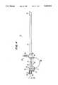
- FIG. 1is a perspective view of one improved resectoscope embodiment made in accordance with the principles of the present invention, but with an improved adjustable grip guard assembly associated therewith;
- FIG. 2is an elevational view of a resectoscope depicted in FIG. 1;
- FIG. 3is a elevational view, partly in cross-section, of an outer sheath assembly
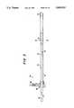
- FIG. 4is an elevational view, partly in cross-section, of an irrigation tube and working element assembly
- FIG. 5is a cross-sectional view of the irrigation tube assembly depicting an improved guide and stabilizing assembly
- FIG. 6is an elevational view of a telescopic and electrode guide assembly made according to the present invention.
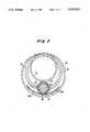
- FIG. 7is a cross-sectional view taken along section line 7--7 appearing in FIG. 5 including an electrode and wing assembly;
- FIG. 8is a front perspective view of a working member made according to the principles of the present invention.
- FIG. 9is an end view of the resectoscope with portions omitted but illustrating the telescopic eyepiece and the improved electrode positioning assembly of the present invention.
- FIGS. 10a and 10billustrate elevational and bottom views; respectively, of a guide made according to the present invention
- FIG. 11is an enlarged and fragmented view, partly in section, illustrating the cooperation between the electrode assembly, telescopic assembly, and guide assembly of the present invention
- FIG. 12is a plan view of one particular type of electrode assembly which is usable in conjunction with the present invention.
- FIG. 13is an enlarged end view of the resecting electrode configuration.
- the improved resectoscope 10includes an outer sheath assembly 12, telescopic assembly 14, electrode positioning assembly 16, and electrode assembly 18.
- the telescopic assembly 14permits a Missionst to view the operation.
- a rod lens system 20having located at a proximal end thereof a suitable eyepiece 22 and a lightsource assembly 24 which is operable for providing illumination during performance of an operation.
- the telescopic assembly 14includes a telescopic tube 20 made of stainless steel which carries the optics. The tube 20 extends into the outer sheath assembly 12 as well as through the electrode positioning assembly 16 in a manner which is conventional.
- the telescopic assembly 14includes a scope locking collar assembly 26 including a scope locking collar pin 28 that is operable to removably secure the telescopic tube 20 to the collar 26.
- a spring guide rod 30is secured at one end to a backstop 31 of the locking collar assembly 26 and at the other end to the front stop 38.
- a telescopic guide tube 32is connected to the locking collar assembly 26 at one end, as shown best in FIG. 4, and cooperates as by being spot welded at the other end with the irrigation tube 70.
- the guide tube 32provides a housing for the scope tube 20.
- the telescopic assembly 14 preferred for usecan be a Hysteroscope 30° Assembly available from CooperSurgical. Of course, other types of scopes can be used.
- FIGS. 1, 2, 4, 8 and 9for illustrating the electrode positioning assembly 16.
- the electrode positioning assembly 16is mounted on the telescopic guide tube 32 and the spring guide rod 30 for reciprocal movement relative thereto between a non-resecting position, and a resecting position; as will be described hereinafter.
- the electrode positioning assembly 16is seen to comprise a central block or working member assembly 34 and a flat bowed compression spring 36 which has one of its terminal end portions affixed to the central block assembly 34 and its other end to the front stop 38 (FIGS. 2 and 4).
- the compression spring 36functions to urge the central block assembly 34 against the backstop 31 and forces a tip of the electrode assembly 18 to its withdrawn or non-resecting condition within the insulation tip 72.
- the spring 36provides a biasing resistance which theêtst must overcome when effecting operation of the resectoscope 10 so as to drive the electrode assembly 18 to its resecting or extended position (not shown).
- the spring rate of the spring 36be selected so that it gradually forces the central block assembly 34 to the position depicted in FIGS. 1, 2 and 4.
- FIGS. 1-3for better illustrating the outer sheath assembly 12 which has secured thereto an interlock 68 attached to front stop 38.
- the stop member 38also allows the guide tube 32 to extend through it.
- one end of the compression spring 36is also secured to the front stop member 38 and the electrode positioning member 16 is adapted to abut against the front stop member 38 so as to inhibit forward movement thereof and thereby define the extent the electrode assembly extends from it.
- a handle assembly 40is connected to the outer sheath assembly 12 and includes diametrically opposed and generally vertical finger grip surfaces 42 on a finger grip.
- the finger grip surfaces 42define an annular recess 44 for receiving a sleeve segment 46 of a drip ring or shield 48 that is affixed appropriately to a tubular elongated outer sheath 50.
- the present inventionalso envisions an adjustable drip shield 48' as seen in FIG. 1 which is selectively positionable along the length of the outer sheath 50 so that different operations and patients can be easily accommodated.
- the outer sheath 50is made of an appropriate stainless steel member that is sized for effecting the type of operation desired (e.g.
- the sheath 50is dimensioned for use in effecting uterus operations and thus is adapted to be inserted in the cervix.
- the outer sheathcan be provided with a plurality of circumferential rows of aspiration openings 51 which are sized to aspirate the vaporized tissue, etc. by having the apertures arranged circumferential (e.g. 360° ) is that they permit a Missionst to rotate the sheath relative to the patient for effecting different types of operations (e.g., urological and gynecological) without suffering a diminishment of the aspirating functions.
- the aspiration tube assemblyincludes an aspiration tube 54 that is connectable at one end through a stop cock 56 to a source of negative pressure or gravity (not shown). At another end, the aspirating tube 54 terminates at an opening 58 in a female sheath interlock member 60 which is connected to the outer sheath 50. A locking collar 62 having a collar pin 63 is connected to the interlock 60. Aspiration is performed in a conventional manner. In this regard, the stop cock 56 is operated so as to allow a Missionst to control the flow rate of aspiration.
- FIGS. 4 and 5for illustrating an irrigation tube assembly 64.
- an inlet stop cock 66 assemblythat is fluidly coupled to a male sheath interlock 68.
- the interlock 68is selectively coupled to the female interlock 60 by the locking collar 62.
- the stop cock 66allows regulation of the flow of irrigation fluid from a suitable source (not shown) to the surgical site.
- the irrigation tube 70is provided with an insulation tip 72.
- the guide tube assembly 74includes the telescopic guide tube 32 which serves essentially to support the telescopic scope 20 and an elongated electrode guide tube 76 which is soldered beneath and along a length of the telescopic guide tube 32 to form an integral unit (FIG. 6). Included in the guide tube assembly 74 is an electrode guide ring 78 which is secured, as by spot welding, at its upper end to the inner periphery of the irrigation tube 70. It is also brazed to the guide tube 32 and soldered to the electrode guide tube 76. As seen in FIGS.
- the guide ring 78defines a funnel like body 80 having a longitudinal space 81 between its longitudinal edges 82. The edges 82 are soldered against a distal end portion of the electrode guide tube 76. As seen in FIG. 7, the guide ring 78 blocks insertion of the electrode in the tube 70. Thus, when the scope 20 (not shown) is within tube 32 the only area open to insertion of the electrode is open tube 76. Because of the construction of the guide ring 78, improper insertion of the electrode into the irrigation tube is minimized since insertion of the electrode is blocked except for the tube 76. Hence, the electrode assembly can be easily inserted through the tube 76.
- FIGS. 11-13for illustrating the electrode assembly 18.
- the electrode assembly 18has its proximal end portion 83 appropriately and removably attached to a source of High Frequency (H.F.) power connectable to the central block assembly 34, as will be described.
- the distal end of the electrode assembly 18has a cutting loop 84 which extends from a pair of forked and insulated current carrying arms 86.
- the arms 86are crimped and soldered together and define a shank portion 87 which is insertable through the electrode guide tube 76, as depicted in FIG. 6.
- the electrode assembly 18can be of any known type suitable for use in a resectoscope.
- the cutting loop 84as depicted in FIG.
- the electrode assembly 18is provided with a one piece stability member 88 having a pair of wings 88a.
- the arcuate stability wings 88aserve as stabilizing means and also cooperate with the guide ring 78 and the irrigation tube 70 for insuring proper insertion of the electrode assembly 18 through the guide tube 76.
- the electrode stability wings 88aprovide an anti-reversing function for further insuring proper installation of the electrode assembly into the guide tube 76.
- the central block assembly 34is depicted as having a plurality of generally rectangular thumb engaging projections 90 which can be made of any suitable material.
- the projections 90are spaced relative to one another and each is adapted to be engaged by a surgeonst's thumb for allowing application of forces thereto so as to displace the same and displace the electrode assembly 18 such that the resection loop 84 extends from the outer sheath 50 for effecting resection.
- the procedurist's thumbis able to move freely from side projection to side projection and well as inferiorly of the central block assembly 34 to the depending projection 90.
- the projections 90have slightly inclined radiused or flared edges 92 relative to a vertical plane so as to even better facilitate a user applying thumb pressure to the slidable central block assembly 34. Because of this construction the aceast is better able to repeatedly and ergonomically force the electrode assembly 18 from the housing for purposes of effecting resection at the surgical site during an operation in a manner in which promotes surgical confidence regardless of prior type of resectoscope. Also, as earlier noted theêtst's thumb need not be used for withdrawing the electrode.
- the central block assembly 34has an opening 96 adapted to removably receive the proximal end 83 of the electrode assembly 18.
- An electrode contact 98has an opening 100 for reception of the electrode end and is therefore aligned with a passage (not shown) communicating with opening 96.
- the contact 98is pivotally mounted by pin 102 to a High Frequency (HF) connector pin contact 104 that has a threaded opening 106 for connection to a High Frequency (HF) cable pin 108.
- a plug 110covers the opening.
- a depressible push button 112fits into an opening in the block 34 and is retained for limited sliding movement by retaining screw 114.
- a spring 116 mounted in the blocktends to bias the contact 98 upwardly.
- the push button 112When the electrodes' proximal end 83 is desired to be inserted, the push button 112 is depressed so that the opening 100 is in registry with opening 96. To latch the electrode assembly 18, the button 112 is released and the spring 116 drives the contact 98 upwardly against inner surfaces of the block 34, thereby retaining the electrode.
- the inventionenvisions other ways of releasably securing the electrode to a source of High Frequency power.
Landscapes
- Health & Medical Sciences (AREA)
- Surgery (AREA)
- Engineering & Computer Science (AREA)
- Life Sciences & Earth Sciences (AREA)
- Biomedical Technology (AREA)
- Molecular Biology (AREA)
- Nuclear Medicine, Radiotherapy & Molecular Imaging (AREA)
- Plasma & Fusion (AREA)
- Physics & Mathematics (AREA)
- Heart & Thoracic Surgery (AREA)
- Medical Informatics (AREA)
- Otolaryngology (AREA)
- Animal Behavior & Ethology (AREA)
- General Health & Medical Sciences (AREA)
- Public Health (AREA)
- Veterinary Medicine (AREA)
- Surgical Instruments (AREA)
- Endoscopes (AREA)
Abstract
Description
Claims (7)
Priority Applications (1)
| Application Number | Priority Date | Filing Date | Title |
|---|---|---|---|
| US08/033,541US5423813A (en) | 1993-03-18 | 1993-03-18 | Resectoscope and electrode assembly |
Applications Claiming Priority (1)
| Application Number | Priority Date | Filing Date | Title |
|---|---|---|---|
| US08/033,541US5423813A (en) | 1993-03-18 | 1993-03-18 | Resectoscope and electrode assembly |
Publications (1)
| Publication Number | Publication Date |
|---|---|
| US5423813Atrue US5423813A (en) | 1995-06-13 |
Family
ID=21871007
Family Applications (1)
| Application Number | Title | Priority Date | Filing Date |
|---|---|---|---|
| US08/033,541Expired - Fee RelatedUS5423813A (en) | 1993-03-18 | 1993-03-18 | Resectoscope and electrode assembly |
Country Status (1)
| Country | Link |
|---|---|
| US (1) | US5423813A (en) |
Cited By (33)
| Publication number | Priority date | Publication date | Assignee | Title |
|---|---|---|---|---|
| USD385351S (en)* | 1995-12-06 | 1997-10-21 | Northgate Technologies Incorporated | Tip portion of a resectoscope electrode |
| WO1998003122A1 (en)* | 1996-07-19 | 1998-01-29 | Karl Storz Gmbh & Co. | Instrument for cutting tissue using high-frequency current |
| WO1998015230A1 (en)* | 1996-10-07 | 1998-04-16 | Symbiosis Corporation | Improved loop electrodes for electrocautery probes for use with a resectoscope |
| US5782829A (en)* | 1995-12-06 | 1998-07-21 | Northgate Technologies Incorporated | Resectoscope electrode assembly and methods of use |
| USD401338S (en) | 1996-06-18 | 1998-11-17 | Northgate Technologies, Inc. | Tip of a resectoscope electrode assembly design |
| US5857962A (en)* | 1997-03-13 | 1999-01-12 | Circon Corporation | Resectoscope with curved electrode channel and resiliently deflectable electrode section |
| US5925040A (en)* | 1997-06-18 | 1999-07-20 | Medical Scientific, Inc. | Electrosurgical instrument having a segmented roller electrode |
| US6071283A (en)* | 1997-06-06 | 2000-06-06 | Medical Scientific, Inc. | Selectively coated electrosurgical instrument |
| US6080152A (en)* | 1998-06-05 | 2000-06-27 | Medical Scientific, Inc. | Electrosurgical instrument |
| US6162239A (en)* | 1996-07-11 | 2000-12-19 | Karl Storz Gmbh & Co. Kg | Instrument with independent pliers |
| US6325801B1 (en) | 1999-12-04 | 2001-12-04 | Karl Storz Gmbh & Co. Kg | Instrument for severing tissue with HF current |
| US6394949B1 (en) | 1998-10-05 | 2002-05-28 | Scimed Life Systems, Inc. | Large area thermal ablation |
| US6428503B1 (en) | 1999-01-19 | 2002-08-06 | Atc Technologies, Inc. | Surgical instrument for providing suction and irrigation |
| US20030149442A1 (en)* | 2002-02-04 | 2003-08-07 | Gellman Barry N. | Resistance heated tissue morcellation |
| DE10248839A1 (en)* | 2002-10-19 | 2004-05-06 | Olympus Winter & Ibe Gmbh | Urological resectoscope with non-rotating instrument holder |
| US7867163B2 (en) | 1998-06-22 | 2011-01-11 | Maquet Cardiovascular Llc | Instrument and method for remotely manipulating a tissue structure |
| US7938842B1 (en) | 1998-08-12 | 2011-05-10 | Maquet Cardiovascular Llc | Tissue dissector apparatus |
| US7972265B1 (en) | 1998-06-22 | 2011-07-05 | Maquet Cardiovascular, Llc | Device and method for remote vessel ligation |
| US7981133B2 (en) | 1995-07-13 | 2011-07-19 | Maquet Cardiovascular, Llc | Tissue dissection method |
| US8241210B2 (en) | 1998-06-22 | 2012-08-14 | Maquet Cardiovascular Llc | Vessel retractor |
| USD667114S1 (en)* | 2011-03-31 | 2012-09-11 | Karl Storz Gmbh & Co. Kg | Gynecological examination sheath |
| CN106691581A (en)* | 2016-11-30 | 2017-05-24 | 大连科万维医疗科技有限公司 | Multifunctional high-frequency electrosurgical pencil |
| JP2018519875A (en)* | 2015-05-20 | 2018-07-26 | アーベー メディカ | Device for excising tissue in the body cavity of the body |
| WO2018229219A1 (en)* | 2017-06-14 | 2018-12-20 | Olympus Winter & Ibe Gmbh | Carrier of a resectoscope and electrode instrument |
| US10299770B2 (en) | 2006-06-01 | 2019-05-28 | Maquet Cardiovascular Llc | Endoscopic vessel harvesting system components |
| US10383682B2 (en) | 2015-08-28 | 2019-08-20 | Covidien Lp | Powered bipolar resectoscope |
| US10507012B2 (en) | 2000-11-17 | 2019-12-17 | Maquet Cardiovascular Llc | Vein harvesting system and method |
| US20200246038A1 (en)* | 2019-02-05 | 2020-08-06 | Olympus Winter & Ibe Gmbh | Irrigation fluid for resection |
| US10813685B2 (en) | 2014-09-25 | 2020-10-27 | Covidien Lp | Single-handed operable surgical instrument including loop electrode with integrated pad electrode |
| US10869716B2 (en) | 2015-08-28 | 2020-12-22 | Covidien Lp | Powered bipolar resectoscope |
| CN112672704A (en)* | 2018-09-13 | 2021-04-16 | 奥林巴斯株式会社 | Treatment tool for endoscope |
| US11819264B2 (en) | 2019-02-05 | 2023-11-21 | Olympus Winter & Ibe Gmbh | Detachable insulating insert for use in a resectoscope |
| US12251157B2 (en) | 2019-03-13 | 2025-03-18 | Olympus Winter & Ibe Gmbh | Electrode instrument and resectoscope with gripping function |
Citations (48)
| Publication number | Priority date | Publication date | Assignee | Title |
|---|---|---|---|---|
| US538971A (en)* | 1895-05-07 | Michael f | ||
| US712989A (en)* | 1902-09-08 | 1902-11-04 | William E Washburn | Electric cautery. |
| FR684198A (en)* | 1929-10-30 | 1930-06-23 | Retractable curette | |
| US1930214A (en)* | 1931-03-23 | 1933-10-10 | Wappler Frederick Charles | Surgical electrode |
| US2120598A (en)* | 1937-03-06 | 1938-06-14 | George H Beuoy | Electrical cutting instrument |
| US3149633A (en)* | 1961-06-15 | 1964-09-22 | Frank G Zingale | Resectoscope |
| US3752159A (en)* | 1971-05-03 | 1973-08-14 | American Cystoscope Makers Inc | Resectoscope cutting electrode |
| US3850175A (en)* | 1972-07-03 | 1974-11-26 | J Lglesias | Resectoscope with continuous irrigation |
| US3856015A (en)* | 1972-01-21 | 1974-12-24 | J Iglesias | Stabilized cutting loop for resectoscope |
| US3898991A (en)* | 1972-12-20 | 1975-08-12 | Olympus Optical Co | Electrosurgical apparatus and method of operating same |
| US3901242A (en)* | 1974-05-30 | 1975-08-26 | Storz Endoskop Gmbh | Electric surgical instrument |
| US3910279A (en)* | 1973-06-20 | 1975-10-07 | Olympus Optical Co | Electrosurgical instrument |
| US3939839A (en)* | 1974-06-26 | 1976-02-24 | American Cystoscope Makers, Inc. | Resectoscope and electrode therefor |
| US3942530A (en)* | 1973-09-03 | 1976-03-09 | Akademiet For De Tekniske Videnskaber, Svejsecentralen | Prostate resectoscope having ultrasonic scanning |
| US3973568A (en)* | 1972-01-21 | 1976-08-10 | Iglesias Jose J | Stabilized cutting loop for resectoscope with unimpaired vision of the operative field |
| US3990456A (en)* | 1975-04-22 | 1976-11-09 | Iglesias Jose J | Anti-arcing resectoscope loop |
| US4024869A (en)* | 1974-12-20 | 1977-05-24 | Richard Wolf Gmbh | Resectoscopes |
| US4030502A (en)* | 1975-12-05 | 1977-06-21 | Jose Juan Iglesias | Anti-arcing resectoscope |
| US4060087A (en)* | 1975-06-11 | 1977-11-29 | Richard Wolf Gmbh | Single or double-shank cutting loop device for resectoscopes |
| US4068667A (en)* | 1976-09-03 | 1978-01-17 | Iglesias Jose J | Anti-arcing resectoscope |
| US4116198A (en)* | 1975-05-15 | 1978-09-26 | Delma, Elektro Und Medizinische Apparatebaugesellschaft M.B.H. | Electro - surgical device |
| US4132227A (en)* | 1974-08-08 | 1979-01-02 | Winter & Ibe | Urological endoscope particularly resectoscope |
| US4134406A (en)* | 1976-10-19 | 1979-01-16 | Iglesias Jose J | Cutting loop for suction resectoscopes |
| US4149538A (en)* | 1977-08-15 | 1979-04-17 | American Hospital Supply Corporation | Resectoscope electrode assembly with non-conductive bearing tube and method of making the same |
| US4181131A (en)* | 1977-02-28 | 1980-01-01 | Olympus Optical Co., Ltd. | High frequency electrosurgical instrument for cutting human body cavity structures |
| US4362160A (en)* | 1979-07-24 | 1982-12-07 | Richard Wolf Gmbh | Endoscopes |
| US4423727A (en)* | 1981-04-10 | 1984-01-03 | Jerrold Widran | Continuous flow urological endoscopic apparatus and method of using same |
| US4430996A (en)* | 1979-08-28 | 1984-02-14 | Richard Wolf Gmbh | Resectoscopes |
| US4481948A (en)* | 1980-12-29 | 1984-11-13 | Sole Gary M | Medical instrument, and methods of constructing and utilizing same |
| US4506668A (en)* | 1982-06-23 | 1985-03-26 | Olympus Winter & Ibe Gmbh | Insulated sleeve high frequency resectoscope |
| US4538610A (en)* | 1982-01-14 | 1985-09-03 | Olympus Optical Co., Ltd. | Resectoscope |
| US4552146A (en)* | 1982-05-18 | 1985-11-12 | Myocur, Inc. | Disposable ophthalmic instrument for performing radial keratotomy on the cornea |
| US4569133A (en)* | 1983-01-06 | 1986-02-11 | Sharpoint, Inc. | Depth limited cutter |
| US4625713A (en)* | 1982-12-14 | 1986-12-02 | Olympus Optical Co. Ltd. | Instrument incorporated in a resectoscope |
| US4648399A (en)* | 1984-01-09 | 1987-03-10 | Olympus Optical Co., Ltd. | Resectoscope |
| US4649917A (en)* | 1983-12-26 | 1987-03-17 | Olympus Optical Co., Ltd. | Resectoscope with matching markers and method of assembly |
| US4657018A (en)* | 1983-08-19 | 1987-04-14 | Hakky Said I | Automatic/manual resectoscope |
| US4674503A (en)* | 1981-03-05 | 1987-06-23 | Peyman Gholam A | Controlled depth penetrant apparatus and method |
| US4726370A (en)* | 1985-02-09 | 1988-02-23 | Olympus Optical Co., Ltd. | Resectoscope device |
| US4744361A (en)* | 1986-05-15 | 1988-05-17 | Olympus Optical Co., Ltd. | Resectoscope |
| US4750489A (en)* | 1985-08-29 | 1988-06-14 | Coopervision, Inc. | Radial keratotomy knife and system using same |
| US4776336A (en)* | 1986-10-30 | 1988-10-11 | Olympus Optical Co., Ltd. | Resectoscope |
| US4834095A (en)* | 1988-02-16 | 1989-05-30 | Ipco Corporation | Probe unit for electro-surgical device |
| US4917621A (en)* | 1988-06-02 | 1990-04-17 | Circon Corporation | Resectoscope with improved guide block and electrical plug connection |
| US4917082A (en)* | 1988-06-02 | 1990-04-17 | Circon Corporation | Resectoscope electrode |
| US4919131A (en)* | 1988-06-02 | 1990-04-24 | Circon Corporation | Resectoscope with improved guide block and electrical plug connection |
| US4955884A (en)* | 1988-06-02 | 1990-09-11 | Circon Corporation | System for reducing drag on the movement of an electrode in a resectoscope |
| US5112329A (en)* | 1990-01-05 | 1992-05-12 | Karl Storz | Four joint medical instrument with an endoscope |
- 1993
- 1993-03-18USUS08/033,541patent/US5423813A/ennot_activeExpired - Fee Related
Patent Citations (49)
| Publication number | Priority date | Publication date | Assignee | Title |
|---|---|---|---|---|
| US538971A (en)* | 1895-05-07 | Michael f | ||
| US712989A (en)* | 1902-09-08 | 1902-11-04 | William E Washburn | Electric cautery. |
| FR684198A (en)* | 1929-10-30 | 1930-06-23 | Retractable curette | |
| US1930214A (en)* | 1931-03-23 | 1933-10-10 | Wappler Frederick Charles | Surgical electrode |
| US2120598A (en)* | 1937-03-06 | 1938-06-14 | George H Beuoy | Electrical cutting instrument |
| US3149633A (en)* | 1961-06-15 | 1964-09-22 | Frank G Zingale | Resectoscope |
| US3752159A (en)* | 1971-05-03 | 1973-08-14 | American Cystoscope Makers Inc | Resectoscope cutting electrode |
| US3752159B1 (en)* | 1971-05-03 | 1984-07-17 | ||
| US3856015A (en)* | 1972-01-21 | 1974-12-24 | J Iglesias | Stabilized cutting loop for resectoscope |
| US3973568A (en)* | 1972-01-21 | 1976-08-10 | Iglesias Jose J | Stabilized cutting loop for resectoscope with unimpaired vision of the operative field |
| US3850175A (en)* | 1972-07-03 | 1974-11-26 | J Lglesias | Resectoscope with continuous irrigation |
| US3898991A (en)* | 1972-12-20 | 1975-08-12 | Olympus Optical Co | Electrosurgical apparatus and method of operating same |
| US3910279A (en)* | 1973-06-20 | 1975-10-07 | Olympus Optical Co | Electrosurgical instrument |
| US3942530A (en)* | 1973-09-03 | 1976-03-09 | Akademiet For De Tekniske Videnskaber, Svejsecentralen | Prostate resectoscope having ultrasonic scanning |
| US3901242A (en)* | 1974-05-30 | 1975-08-26 | Storz Endoskop Gmbh | Electric surgical instrument |
| US3939839A (en)* | 1974-06-26 | 1976-02-24 | American Cystoscope Makers, Inc. | Resectoscope and electrode therefor |
| US4132227A (en)* | 1974-08-08 | 1979-01-02 | Winter & Ibe | Urological endoscope particularly resectoscope |
| US4024869A (en)* | 1974-12-20 | 1977-05-24 | Richard Wolf Gmbh | Resectoscopes |
| US3990456A (en)* | 1975-04-22 | 1976-11-09 | Iglesias Jose J | Anti-arcing resectoscope loop |
| US4116198A (en)* | 1975-05-15 | 1978-09-26 | Delma, Elektro Und Medizinische Apparatebaugesellschaft M.B.H. | Electro - surgical device |
| US4060087A (en)* | 1975-06-11 | 1977-11-29 | Richard Wolf Gmbh | Single or double-shank cutting loop device for resectoscopes |
| US4030502A (en)* | 1975-12-05 | 1977-06-21 | Jose Juan Iglesias | Anti-arcing resectoscope |
| US4068667A (en)* | 1976-09-03 | 1978-01-17 | Iglesias Jose J | Anti-arcing resectoscope |
| US4134406A (en)* | 1976-10-19 | 1979-01-16 | Iglesias Jose J | Cutting loop for suction resectoscopes |
| US4181131A (en)* | 1977-02-28 | 1980-01-01 | Olympus Optical Co., Ltd. | High frequency electrosurgical instrument for cutting human body cavity structures |
| US4149538A (en)* | 1977-08-15 | 1979-04-17 | American Hospital Supply Corporation | Resectoscope electrode assembly with non-conductive bearing tube and method of making the same |
| US4362160A (en)* | 1979-07-24 | 1982-12-07 | Richard Wolf Gmbh | Endoscopes |
| US4430996A (en)* | 1979-08-28 | 1984-02-14 | Richard Wolf Gmbh | Resectoscopes |
| US4481948A (en)* | 1980-12-29 | 1984-11-13 | Sole Gary M | Medical instrument, and methods of constructing and utilizing same |
| US4674503A (en)* | 1981-03-05 | 1987-06-23 | Peyman Gholam A | Controlled depth penetrant apparatus and method |
| US4423727A (en)* | 1981-04-10 | 1984-01-03 | Jerrold Widran | Continuous flow urological endoscopic apparatus and method of using same |
| US4538610A (en)* | 1982-01-14 | 1985-09-03 | Olympus Optical Co., Ltd. | Resectoscope |
| US4552146A (en)* | 1982-05-18 | 1985-11-12 | Myocur, Inc. | Disposable ophthalmic instrument for performing radial keratotomy on the cornea |
| US4506668A (en)* | 1982-06-23 | 1985-03-26 | Olympus Winter & Ibe Gmbh | Insulated sleeve high frequency resectoscope |
| US4625713A (en)* | 1982-12-14 | 1986-12-02 | Olympus Optical Co. Ltd. | Instrument incorporated in a resectoscope |
| US4569133A (en)* | 1983-01-06 | 1986-02-11 | Sharpoint, Inc. | Depth limited cutter |
| US4657018A (en)* | 1983-08-19 | 1987-04-14 | Hakky Said I | Automatic/manual resectoscope |
| US4649917A (en)* | 1983-12-26 | 1987-03-17 | Olympus Optical Co., Ltd. | Resectoscope with matching markers and method of assembly |
| US4648399A (en)* | 1984-01-09 | 1987-03-10 | Olympus Optical Co., Ltd. | Resectoscope |
| US4726370A (en)* | 1985-02-09 | 1988-02-23 | Olympus Optical Co., Ltd. | Resectoscope device |
| US4750489A (en)* | 1985-08-29 | 1988-06-14 | Coopervision, Inc. | Radial keratotomy knife and system using same |
| US4744361A (en)* | 1986-05-15 | 1988-05-17 | Olympus Optical Co., Ltd. | Resectoscope |
| US4776336A (en)* | 1986-10-30 | 1988-10-11 | Olympus Optical Co., Ltd. | Resectoscope |
| US4834095A (en)* | 1988-02-16 | 1989-05-30 | Ipco Corporation | Probe unit for electro-surgical device |
| US4917621A (en)* | 1988-06-02 | 1990-04-17 | Circon Corporation | Resectoscope with improved guide block and electrical plug connection |
| US4917082A (en)* | 1988-06-02 | 1990-04-17 | Circon Corporation | Resectoscope electrode |
| US4919131A (en)* | 1988-06-02 | 1990-04-24 | Circon Corporation | Resectoscope with improved guide block and electrical plug connection |
| US4955884A (en)* | 1988-06-02 | 1990-09-11 | Circon Corporation | System for reducing drag on the movement of an electrode in a resectoscope |
| US5112329A (en)* | 1990-01-05 | 1992-05-12 | Karl Storz | Four joint medical instrument with an endoscope |
Cited By (49)
| Publication number | Priority date | Publication date | Assignee | Title |
|---|---|---|---|---|
| US5957923A (en)* | 1995-04-20 | 1999-09-28 | Symbiosis Corporation | Loop electrodes for electrocautery probes for use with a resectoscope |
| US7981133B2 (en) | 1995-07-13 | 2011-07-19 | Maquet Cardiovascular, Llc | Tissue dissection method |
| US5782829A (en)* | 1995-12-06 | 1998-07-21 | Northgate Technologies Incorporated | Resectoscope electrode assembly and methods of use |
| USD385351S (en)* | 1995-12-06 | 1997-10-21 | Northgate Technologies Incorporated | Tip portion of a resectoscope electrode |
| USD401338S (en) | 1996-06-18 | 1998-11-17 | Northgate Technologies, Inc. | Tip of a resectoscope electrode assembly design |
| US6162239A (en)* | 1996-07-11 | 2000-12-19 | Karl Storz Gmbh & Co. Kg | Instrument with independent pliers |
| WO1998003122A1 (en)* | 1996-07-19 | 1998-01-29 | Karl Storz Gmbh & Co. | Instrument for cutting tissue using high-frequency current |
| WO1998015230A1 (en)* | 1996-10-07 | 1998-04-16 | Symbiosis Corporation | Improved loop electrodes for electrocautery probes for use with a resectoscope |
| US5857962A (en)* | 1997-03-13 | 1999-01-12 | Circon Corporation | Resectoscope with curved electrode channel and resiliently deflectable electrode section |
| US6071283A (en)* | 1997-06-06 | 2000-06-06 | Medical Scientific, Inc. | Selectively coated electrosurgical instrument |
| US5925040A (en)* | 1997-06-18 | 1999-07-20 | Medical Scientific, Inc. | Electrosurgical instrument having a segmented roller electrode |
| US6080152A (en)* | 1998-06-05 | 2000-06-27 | Medical Scientific, Inc. | Electrosurgical instrument |
| US8241210B2 (en) | 1998-06-22 | 2012-08-14 | Maquet Cardiovascular Llc | Vessel retractor |
| US7867163B2 (en) | 1998-06-22 | 2011-01-11 | Maquet Cardiovascular Llc | Instrument and method for remotely manipulating a tissue structure |
| US7972265B1 (en) | 1998-06-22 | 2011-07-05 | Maquet Cardiovascular, Llc | Device and method for remote vessel ligation |
| US9730782B2 (en) | 1998-08-12 | 2017-08-15 | Maquet Cardiovascular Llc | Vessel harvester |
| US9700398B2 (en) | 1998-08-12 | 2017-07-11 | Maquet Cardiovascular Llc | Vessel harvester |
| US8986335B2 (en) | 1998-08-12 | 2015-03-24 | Maquet Cardiovascular Llc | Tissue dissector apparatus and method |
| US8460331B2 (en) | 1998-08-12 | 2013-06-11 | Maquet Cardiovascular, Llc | Tissue dissector apparatus and method |
| US7938842B1 (en) | 1998-08-12 | 2011-05-10 | Maquet Cardiovascular Llc | Tissue dissector apparatus |
| US6394949B1 (en) | 1998-10-05 | 2002-05-28 | Scimed Life Systems, Inc. | Large area thermal ablation |
| US20060020264A1 (en)* | 1998-10-05 | 2006-01-26 | Boston Scientific Scimed, Inc. | Large area thermal ablation |
| US20100256632A1 (en)* | 1998-10-05 | 2010-10-07 | Boston Scientific Scimed, Inc. | Large area thermal ablation |
| US7749159B2 (en) | 1998-10-05 | 2010-07-06 | Boston Scientific Scimed, Inc. | Large area thermal ablation |
| US6932812B2 (en) | 1998-10-05 | 2005-08-23 | Scimed Life Systems, Inc. | Large area thermal ablation |
| US6428503B1 (en) | 1999-01-19 | 2002-08-06 | Atc Technologies, Inc. | Surgical instrument for providing suction and irrigation |
| US6325801B1 (en) | 1999-12-04 | 2001-12-04 | Karl Storz Gmbh & Co. Kg | Instrument for severing tissue with HF current |
| US10507012B2 (en) | 2000-11-17 | 2019-12-17 | Maquet Cardiovascular Llc | Vein harvesting system and method |
| US6997926B2 (en) | 2002-02-04 | 2006-02-14 | Boston Scientific Scimed, Inc. | Resistance heated tissue morcellation |
| US20030149442A1 (en)* | 2002-02-04 | 2003-08-07 | Gellman Barry N. | Resistance heated tissue morcellation |
| US20060009761A1 (en)* | 2002-10-19 | 2006-01-12 | Thomas Aue | Urological resectoscope having a non-rotating instrument support |
| DE10248839A1 (en)* | 2002-10-19 | 2004-05-06 | Olympus Winter & Ibe Gmbh | Urological resectoscope with non-rotating instrument holder |
| DE10393537B4 (en)* | 2002-10-19 | 2014-02-13 | Olympus Winter & Ibe Gmbh | Urological resectoscope with torsion-protected instrument carrier |
| US7488318B2 (en) | 2002-10-19 | 2009-02-10 | Olympus Winter & Ibe Gmbh | Urological resectoscope having a non-rotating instrument support |
| US11134835B2 (en) | 2006-06-01 | 2021-10-05 | Maquet Cardiovascular Llc | Endoscopic vessel harvesting system components |
| US10299770B2 (en) | 2006-06-01 | 2019-05-28 | Maquet Cardiovascular Llc | Endoscopic vessel harvesting system components |
| USD667114S1 (en)* | 2011-03-31 | 2012-09-11 | Karl Storz Gmbh & Co. Kg | Gynecological examination sheath |
| US10813685B2 (en) | 2014-09-25 | 2020-10-27 | Covidien Lp | Single-handed operable surgical instrument including loop electrode with integrated pad electrode |
| JP2018519875A (en)* | 2015-05-20 | 2018-07-26 | アーベー メディカ | Device for excising tissue in the body cavity of the body |
| US10383682B2 (en) | 2015-08-28 | 2019-08-20 | Covidien Lp | Powered bipolar resectoscope |
| US10869716B2 (en) | 2015-08-28 | 2020-12-22 | Covidien Lp | Powered bipolar resectoscope |
| CN106691581A (en)* | 2016-11-30 | 2017-05-24 | 大连科万维医疗科技有限公司 | Multifunctional high-frequency electrosurgical pencil |
| WO2018229219A1 (en)* | 2017-06-14 | 2018-12-20 | Olympus Winter & Ibe Gmbh | Carrier of a resectoscope and electrode instrument |
| CN112672704A (en)* | 2018-09-13 | 2021-04-16 | 奥林巴斯株式会社 | Treatment tool for endoscope |
| CN112672704B (en)* | 2018-09-13 | 2024-04-26 | 奥林巴斯株式会社 | Treatment tool for endoscope |
| US20200246038A1 (en)* | 2019-02-05 | 2020-08-06 | Olympus Winter & Ibe Gmbh | Irrigation fluid for resection |
| US11633204B2 (en)* | 2019-02-05 | 2023-04-25 | Olympus Winter & Ibe Gmbh | Irrigation fluid for resection |
| US11819264B2 (en) | 2019-02-05 | 2023-11-21 | Olympus Winter & Ibe Gmbh | Detachable insulating insert for use in a resectoscope |
| US12251157B2 (en) | 2019-03-13 | 2025-03-18 | Olympus Winter & Ibe Gmbh | Electrode instrument and resectoscope with gripping function |
Similar Documents
| Publication | Publication Date | Title |
|---|---|---|
| US5423813A (en) | Resectoscope and electrode assembly | |
| US11864819B2 (en) | Adjustable electrosurgical pencil with slidable vent tube | |
| US5374244A (en) | Disposable lavage | |
| US6193716B1 (en) | Electrosurgical device for uvulopalatoplasty | |
| EP2890320B1 (en) | Bi-polar surgical instrument | |
| US5338292A (en) | Disposable lavage with instrument shield | |
| US5250065A (en) | Disposable lavage tip assembly | |
| JP3423733B2 (en) | Endoscopic surgical instruments for suction and irrigation | |
| EP0684015B1 (en) | Electrosurgical device | |
| EP1902682A2 (en) | Length adjustable electro-surgical pencil with suction means | |
| US6923756B2 (en) | Multifunctional medical tool | |
| CN111839722A (en) | A laparoscopic multifunctional electrocoagulation dissecting aspirator | |
| EP0549712A1 (en) | Disposable lavage | |
| CA2883232C (en) | Adjustable electrosurgical pencil with slidable vent tube | |
| JPH01121036A (en) | Resectoscope |
Legal Events
| Date | Code | Title | Description |
|---|---|---|---|
| AS | Assignment | Owner name:COOPERSURGICAL, CONNECTICUT Free format text:ASSIGNMENT OF ASSIGNORS INTEREST;ASSIGNORS:KAISER, MARK S.;POTOCKY, CLIFFORD F.;REEL/FRAME:006933/0316 Effective date:19940323 | |
| AS | Assignment | Owner name:KEYBANK NATIONAL ASSOCIATION, NEW YORK Free format text:SECURITY AGREEMENT;ASSIGNOR:COOPERSURGICAL, INC.;REEL/FRAME:008811/0228 Effective date:19970915 | |
| REMI | Maintenance fee reminder mailed | ||
| LAPS | Lapse for failure to pay maintenance fees | ||
| FP | Lapsed due to failure to pay maintenance fee | Effective date:19990613 | |
| AS | Assignment | Owner name:COOPERVISION TECHNOLOGY, INC., CALIFORNIA Free format text:ASSIGNMENT OF ASSIGNORS INTEREST;ASSIGNOR:COOPERVISION, INC.;REEL/FRAME:010371/0476 Effective date:19991026 | |
| FEPP | Fee payment procedure | Free format text:PAYOR NUMBER ASSIGNED (ORIGINAL EVENT CODE: ASPN); ENTITY STATUS OF PATENT OWNER: LARGE ENTITY | |
| AS | Assignment | Owner name:COOPERSURGICAL, INC., CALIFORNIA Free format text:PATENT RELEASE;ASSIGNOR:KEYBANK NATIONAL ASSOCIATION;REEL/FRAME:015740/0954 Effective date:20050209 | |
| STCH | Information on status: patent discontinuation | Free format text:PATENT EXPIRED DUE TO NONPAYMENT OF MAINTENANCE FEES UNDER 37 CFR 1.362 |