US5423330A - Capsule suction punch instrument and method of use - Google Patents
Capsule suction punch instrument and method of useDownload PDFInfo
- Publication number
- US5423330A US5423330AUS08/029,398US2939893AUS5423330AUS 5423330 AUS5423330 AUS 5423330AUS 2939893 AUS2939893 AUS 2939893AUS 5423330 AUS5423330 AUS 5423330A
- Authority
- US
- United States
- Prior art keywords
- cutting
- tubular body
- actuating element
- cutting member
- surgical instrument
- Prior art date
- Legal status (The legal status is an assumption and is not a legal conclusion. Google has not performed a legal analysis and makes no representation as to the accuracy of the status listed.)
- Expired - Lifetime
Links
- 238000000034methodMethods0.000titleclaimsabstractdescription9
- 239000002775capsuleSubstances0.000titledescription13
- 238000005520cutting processMethods0.000claimsabstractdescription248
- 230000003213activating effectEffects0.000claims1
- 238000007789sealingMethods0.000claims1
- 238000001802infusionMethods0.000description6
- 230000007704transitionEffects0.000description6
- 238000004519manufacturing processMethods0.000description3
- 238000001356surgical procedureMethods0.000description3
- 239000006096absorbing agentSubstances0.000description2
- 238000010276constructionMethods0.000description2
- 210000004087corneaAnatomy0.000description2
- 238000000605extractionMethods0.000description2
- 230000035939shockEffects0.000description2
- 241001481828Glyptocephalus cynoglossusSpecies0.000description1
- FAPWRFPIFSIZLT-UHFFFAOYSA-MSodium chlorideChemical compound[Na+].[Cl-]FAPWRFPIFSIZLT-UHFFFAOYSA-M0.000description1
- 238000001574biopsyMethods0.000description1
- 230000000994depressogenic effectEffects0.000description1
- 239000012530fluidSubstances0.000description1
- 239000007943implantSubstances0.000description1
- 238000003780insertionMethods0.000description1
- 230000037431insertionEffects0.000description1
- 239000000463materialSubstances0.000description1
- 239000012528membraneSubstances0.000description1
- 238000012986modificationMethods0.000description1
- 230000004048modificationEffects0.000description1
- 210000000056organAnatomy0.000description1
- 230000000149penetrating effectEffects0.000description1
- 230000035515penetrationEffects0.000description1
- 239000012858resilient materialSubstances0.000description1
- 230000000717retained effectEffects0.000description1
- 239000011780sodium chlorideSubstances0.000description1
- 238000002054transplantationMethods0.000description1
Images


Classifications
- A—HUMAN NECESSITIES
- A61—MEDICAL OR VETERINARY SCIENCE; HYGIENE
- A61B—DIAGNOSIS; SURGERY; IDENTIFICATION
- A61B10/00—Instruments for taking body samples for diagnostic purposes; Other methods or instruments for diagnosis, e.g. for vaccination diagnosis, sex determination or ovulation-period determination; Throat striking implements
- A61B10/02—Instruments for taking cell samples or for biopsy
- A61B10/0233—Pointed or sharp biopsy instruments
- A61B10/0283—Pointed or sharp biopsy instruments with vacuum aspiration, e.g. caused by retractable plunger or by connected syringe
- A—HUMAN NECESSITIES
- A61—MEDICAL OR VETERINARY SCIENCE; HYGIENE
- A61F—FILTERS IMPLANTABLE INTO BLOOD VESSELS; PROSTHESES; DEVICES PROVIDING PATENCY TO, OR PREVENTING COLLAPSING OF, TUBULAR STRUCTURES OF THE BODY, e.g. STENTS; ORTHOPAEDIC, NURSING OR CONTRACEPTIVE DEVICES; FOMENTATION; TREATMENT OR PROTECTION OF EYES OR EARS; BANDAGES, DRESSINGS OR ABSORBENT PADS; FIRST-AID KITS
- A61F9/00—Methods or devices for treatment of the eyes; Devices for putting in contact-lenses; Devices to correct squinting; Apparatus to guide the blind; Protective devices for the eyes, carried on the body or in the hand
- A61F9/007—Methods or devices for eye surgery
- A61F9/00736—Instruments for removal of intra-ocular material or intra-ocular injection, e.g. cataract instruments
- A61F9/00754—Instruments for removal of intra-ocular material or intra-ocular injection, e.g. cataract instruments for cutting or perforating the anterior lens capsule, e.g. capsulotomes
- A—HUMAN NECESSITIES
- A61—MEDICAL OR VETERINARY SCIENCE; HYGIENE
- A61F—FILTERS IMPLANTABLE INTO BLOOD VESSELS; PROSTHESES; DEVICES PROVIDING PATENCY TO, OR PREVENTING COLLAPSING OF, TUBULAR STRUCTURES OF THE BODY, e.g. STENTS; ORTHOPAEDIC, NURSING OR CONTRACEPTIVE DEVICES; FOMENTATION; TREATMENT OR PROTECTION OF EYES OR EARS; BANDAGES, DRESSINGS OR ABSORBENT PADS; FIRST-AID KITS
- A61F9/00—Methods or devices for treatment of the eyes; Devices for putting in contact-lenses; Devices to correct squinting; Apparatus to guide the blind; Protective devices for the eyes, carried on the body or in the hand
- A61F9/007—Methods or devices for eye surgery
- A61F9/013—Instruments for compensation of ocular refraction ; Instruments for use in cornea removal, for reshaping or performing incisions in the cornea
- A—HUMAN NECESSITIES
- A61—MEDICAL OR VETERINARY SCIENCE; HYGIENE
- A61B—DIAGNOSIS; SURGERY; IDENTIFICATION
- A61B17/00—Surgical instruments, devices or methods
- A61B17/32—Surgical cutting instruments
- A61B17/3205—Excision instruments
- A61B17/32053—Punch like cutting instruments, e.g. using a cylindrical or oval knife
- A—HUMAN NECESSITIES
- A61—MEDICAL OR VETERINARY SCIENCE; HYGIENE
- A61B—DIAGNOSIS; SURGERY; IDENTIFICATION
- A61B17/00—Surgical instruments, devices or methods
- A61B17/30—Surgical pincettes, i.e. surgical tweezers without pivotal connections
- A61B2017/306—Surgical pincettes, i.e. surgical tweezers without pivotal connections holding by means of suction
Definitions
- This inventionrelates to an instrument for cutting tissue and, more particularly, to an instrument for creating a hole or flap in the lens capsule of the eye.
- An object of the inventionis to provide an instrument for cutting the lens capsule which overcomes the problems associated with the conventional instruments by producing an incision which resists tearing.
- Another object of the inventionis to provide an instrument for cutting the lens capsule which ensures that a tissue specimen will not be inadvertently cut or punched during positioning of the instrument.
- a further object of the inventionis to provide an instrument which is capable of holding eye tissue during the cutting procedure so as to facilitate a clean cut in the lens capsule.
- a surgical suction punch instrumentwhich includes a tubular body having a proximal portion and a distal portion.
- a cutting memberwhich has a distal cutting edge is longitudinally received within the tubular body for guided reciprocal movement therein between a cutting position wherein the cutting edge projects from the distal portion and a non-cutting position wherein the cutting edge is retracted within the tubular body.
- An urging mechanismis further provided, preferably within the tubular body, for urging the cutting member toward its cutting position.
- a vacuum sourceis coupled to the tubular body and/or the cutting member and provides a vacuum to hold tissue to be cut during the cutting procedure.
- Another object of the present inventionis the provision of the device of the type described, which is simple in construction, effective in operation and economical to manufacture and maintain.
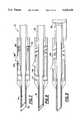
- FIG. 1is a schematic sectional view of an instrument provided in accordance with the invention, shown with its cutting member in a retracted, non-cutting position;
- FIG. 2is a schematic sectional view of the instrument of FIG. 1, shown with its cutting member in transition from a non-cutting to a cutting position;
- FIG. 3is a schematic sectional view of the instrument of FIG. 1, shown with its cutting member in a cutting position;
- FIG. 4is an enlarged schematic sectional view of a portion of the instrument showing a pivoted finger slide
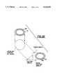
- FIG. 5ais an enlarged view of a distal end of an instrument in accordance with the invention showing a cutting member having a flared blade in a retracted position;
- FIG. 5bis an enlarged view of the distal end of the instrument showing the cutting member with a flared blade in an extended position
- FIG. 6ais a schematic view of the distal portion of the instrument engaging tissue, with a vacuum being exerted on the tissue to hold the tissue prior to cutting;
- FIG. 6bis a schematic view of the distal portion of the instrument with the cutting member cutting the tissue
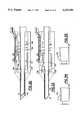
- FIG. 7is a schematic sectional view of a second embodiment of the invention, shown with its cutting member in a retracted, non-cutting position;
- FIG. 8is a schematic sectional view of the instrument of FIG. 7, shown with its cutting member in transition from the non-cutting position to the cutting position;
- FIG. 9is a schematic sectional view of the instrument of FIG. 7, shown with its cutting member in the cutting position;
- FIG. 10is a schematic top plan view of the instrument of FIG. 7;
- FIG. 11is an end view of the cutting member disposed within the distal portion of the tubular body of the instrument
- FIG. 12is a sectional side view of a portion of the cutting member disposed within the distal portion of the tubular body
- FIG. 13is a perspective view of a portion of the cutting member extending from the distal portion of the tubular body
- FIG. 14is a partially cutaway perspective view of a portion of the cutting member retracted within the distal portion of the tubular body
- FIG. 15is a side view of a portion of the cutting member extending from the distal portion of the tubular body
- FIG. 16is an end view of an elliptical cutting member provided in accordance with the invention.
- FIG. 17is a sectional side view of a portion of the elliptical cutting member of FIG. 16, shown disposed within the distal portion of the tubular body;
- FIG. 18is a partial top view of the elliptical cutting member of FIG. 16, shown disposed within the distal portion of the tubular body;
- FIG. 19is an end view of a portion of another elliptical cutting member of the invention.
- FIG. 20is a sectional side view of a portion of the elliptical cutting member of FIG. 19, shown disposed within the distal portion of the tubular body;
- FIG. 21is a partially cutaway top view of a portion of the elliptical cutting member of FIG. 19, shown disposed within the distal portion of the tubular body;
- FIG. 22is a schematic view showing an elliptical cutting member cutting a circular hole
- FIG. 23is a schematic sectional view of a third embodiment of the invention, shown with its cutting member in a retracted, non-cutting position;
- FIG. 24is a schematic sectional view of the instrument of FIG. 23, shown with its cutting member in transition from the non-cutting position to the cutting position;
- FIG. 25is a schematic sectional view of the instrument of FIG. 23, shown with its cutting member in the cutting position;
- FIG. 26is a schematic top plan view of the instrument of FIG. 23;
- FIG. 27is a schematic sectional view of a fourth embodiment of the invention, shown with its cutting member in a retracted, non-cutting position;
- FIG. 28is a schematic sectional view of the instrument of FIG. 27, shown with its cutting member in transition from the non-cutting position to a cutting position;
- FIG. 29is a schematic sectional view of the instrument of FIG. 27, shown with its cutting member in the cutting position;
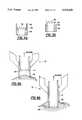
- FIG. 30is a schematic sectional view of a fifth embodiment of the invention, shown with its cutting member in a non-cutting position;
- FIG. 31is a schematic sectional view of the instrument of FIG. 30, shown with its cutting member in transition from the non-cutting position to the cutting position;
- FIG. 32is a schematic sectional view of the instrument of FIG. 30, shown with its spring loaded slide in contact with the thrust plate;
- FIG. 33is a schematic side plan view of the instrument of FIG. 30, shown with its cutting member in the cutting position;
- FIG. 34is a view of a portion of a spring arm of the invention, shown in a relaxed position
- FIG. 35is a view of the spring arm of FIG. 34, shown in a biased position
- FIG. 36is a schematic sectional view of a sixth embodiment of the invention, shown with its cutting member in a retracted, non-cutting position;
- FIG. 37is a schematic sectional view of the instrument of FIG. 36, shown with its cutting member in transition from the non-cutting position to a cutting position;
- FIG. 38is a schematic sectional view of the instrument of FIG. 36, shown with its spring loaded slide in contact with the thrust plate;
- FIG. 39is a schematic side plan view of the instrument of FIG. 36, shown with its cutting member in the cutting position;
- FIG. 40is an end view of the distal portion of the tubular body showing a tissue manipulator disposed thereon;
- FIG. 41is a perspective view of a portion of the distal portion of the tubular body having a partial tissue manipulator
- FIG. 42is a side view of a portion of an angled distal portion of the tubular body having a partial tissue manipulator
- FIG. 43is a side view of a portion of the distal portion of the tubular body having a partial tissue manipulator
- FIG. 44is an end view of the distal portion of the tubular body having a complete tissue manipulator
- FIG. 45is an end view of an elliptical distal portion of the tubular body having a complete tissue manipulator
- FIG. 46is an end view of an elliptical distal portion having a partial tissue manipulator
- FIG. 47is a perspective view of a another embodiment of a portion of the cutting member extending from the distal portion of the tubular body for creating a flap in tissue;
- FIG. 48is a side view of the cutting member of FIG. 47.
- the instrument of the inventionis utilized to hold tissue, such as the lens capsule of the eye, with a vacuum while performing a quick-action cut of the tissue, resulting in a clean circular cut, as shown in FIGS. 6a and 6b.
- tissuesuch as the lens capsule of the eye
- the instrumentreduces the pressure on the inside of the lens capsule.
- the instrumentpermits removal of part of the capsule and lens tissue or creates a flap in the capsule so as to make room for other surgical instruments or implants.
- the instrumentmay be disposed of, or sterilized for further use. It can be appreciated that the instrument can be used to cut eye tissue other than the lens capsule, such as the cornea, and body tissue other than eye tissue.
- the instrument 10includes a tubular body 12 having a distal portion 14, a proximal portion 16 and a mid portion 18.
- the distal portion of the tubular bodyextends from the mid portion and may have a diameter less than that of the mid portion, as shown.
- the edge 22 of the distal portion 14is in a plane perpendicular to the longitudinal axis of tubular body 12 and is blunt.
- the shape of edge 22is chosen to match the contour of the tissue to be cut.
- end or edge 22 of the distal portionmay be angled, as shown in FIG. 7, to properly hold during cutting tissue that is curved.
- a cutting member 24Disposed centrally within the tubular body 12 is a cutting member 24 which is mounted for guided reciprocal movement within the tubular body.
- the cutting member 24is of hollow tubular construction having distal 26 and proximal 28 ends.
- the distal end 26 of the cutting memberincludes a cutting edge or blade 30.
- the cutting blade 30may have a variety of configurations, but each is preferably peripherally continuous, serrated and adapted to make a circular or oval hole.
- FIGS. 5a and 5bshow a cutting blade 30 having a flared end.
- the flared endis provided so there is no gap between the inner side of the distal end 14 and the cutting member 24, while permitting infusion or vacuum to flow through the space between the grooves of the cutting member.
- the flared endalso acts as a spring member to hold the cutting member 24 from sliding until the shoulder means or thrust plate 39 thrusts it forward, as will become more apparent below.
- the proximal end 28 of the cutting member 24is coupled to a flexible tube 32 which is connected to a vacuum source 33, as will become more apparent below.
- an urging mechanismis provided which is coupled to the cutting member 24 so as to urge the cutting member toward a cutting position (FIG. 3) from a non-cutting position (FIG. 1).
- Urging mechanism 34spring loads the cutting member for selective release to cut tissue.
- the urging mechanism 34includes a finger slide 36 disposed about the cutting member 24.
- a spring member 38is disposed forward of the finger slide 36, between the finger slide and a thrust plate 39.
- the thrust plate 39is coupled to the periphery of the cutting member 24.
- the urging mechanismfurther includes a diaphragm member 40 having an outer periphery 42 and an inner periphery 44.
- the outer periphery 42 of the diaphragm member 40is sealingly coupled with the mid portion 18 of the tubular body.
- the inner periphery of the diaphragm memberis sealingly coupled with the cutting member 24.
- the diaphragm member 40is made of resilient material so that when it is moved from a first rest state (FIG. 1) through a cocked or loaded state (FIG. 2) to a second rest state (FIG. 3), the diaphragm member moves the cutting member from the non-cutting position to the cutting position, as will become apparent below.
- the diaphragm member 40further ensures that a vacuum is confined to the cutter and to the distal portion 14 to assist in holding, severing and capturing part of the capsule or other tissue to be severed.
- FIG. 2shows the diaphragm member 40 in a "cocked" state just prior to release.
- the finger slide 36is moved forward with spring 38 compressed.
- Diaphragm member 40is deformed which moves the cutting member 24 slightly forward.
- FIG. 3shows the finger slide 36 moved all the way to the forward end of channel 46.
- the spring member 38forces the thrust plate 39 forward which causes the diaphragm member 40 to spring forward to a rest, released state, thus moving the cutting member to an extended cutting position.
- the distal end 26 of the cutting memberprojects from the distal portion 14 of the tubular body so as to protrude from blunt end 22.
- a stop 48defines an end of channel 46 to limit movement of the finger slide 36 and thus, movement of the cutting member 24.
- the use of the diaphragm member 40 to actuate the cutting memberincreases the speed at which tissue can be cut by the instrument 10.
- the serrated distal end 26 of the cutting memberfacilitates holding, piercing and penetrating of tissue, as shown in FIGS. 6a, 6b.
- the cutting member 24may be filled with a fluid such as saline.
- the inventionprovides an instrument which enables tissue, whether hard or soft, to be effectively held and cut, even at substantial depths, without affecting other adjacent areas.
- FIG. 4shows a variation of the finger slide 36'.
- the slide 36includes a pivot 50 which, when rotated, moves sliding member 52.
- FIG. 4also shows an infusion port 58 connected to the mid portion 18 of the tubular body and communicating with the space between the inner periphery of the distal portion 14 of the tubular body and the outer periphery of the cutting member 24 to provide infusion of materials required during the tissue extraction procedure.
- the infusion portmay also be used to release the vacuum.
- FIGS. 7-10illustrate a second embodiment of the present invention.
- the second embodimentis substantially similar to the first embodiment; however, the urging mechanism 34 has been modified.
- the finger slide 36"is disposed within channel 46.
- the channel 46has a stop 48 at one end thereof and a latch 54 at the opposite end thereof.
- the finger slide 36"is engaged with latch 54 to prevent movement of the cutting member.
- the spring member 38'is disposed rearwardly of the finger slide 36", between the finger slide and surface 56. In the non-cutting position, the cutting member 24 is retracted within the tubular body with the spring member 38' compressed.
- a stop 57is defined by or mounted to the tubular body 12 to engage the thrust plate 39 to limit the movement of the cutting member 24.
- a retracting member 60is provided on the proximal portion of the cutting member 24. Engagement of the finger slide and the retracting member retracts the cutting member during "cocking" of the spring.
- a third embodiment of the present inventionis shown.
- the third embodimentis substantially similar to the second embodiment; however, a triggering mechanism, generally indicated at 64, is employed. It has been found that in using the spring loaded finger slide, the surgeon may move his hand when he pushes the slide 36, which may damage adjacent tissue. Therefore, a remote electric, mechanic or pneumatic tripping device 66 is employed whereby the user's hand can be kept as steady as possible.
- the tripping deviceis disposed in a channel 68. As shown in FIG. 26, the tripping device 66 is remotely actuated to disengage the slide 36 from latch 54.
- FIGS. 27-29disclose a fourth embodiment of the invention having a pneumatically controlled trigger device 70 that is easy to use and simple to manufacture.
- a port 72communicates with the interior of the mid portion 18 of the tubular body so as to move slide member 74, disposed about cutting member 24.
- a pump/vacuum 75is used to move the slide member forward into the cutting position or backward to move the cutting member 24 into the retracted position.
- the slide member 74moves forward, it contacts thrust plate 39 which moves the cutting member 24 forward to extend from end 22.
- a diaphragm seal 78limits the forward movement of cutting member 24.
- Stop 76is provided to limit rearward movement of the slide member 74.
- the diaphragm seal 78is provided at the forward end of the mid portion 18.
- the thrust plateis moved forward to contact the diaphragm seal 78.
- the diaphragm sealensures that the vacuum is only provided within the interior of the cutting member and cannot be released into chamber 41 of mid portion 18 of the tubular body.
- Seals 80 and 82are also provided about the sliding member 74 and about the proximal end of the cutting member 24 so as to prevent loss of vacuum.
- FIGS. 24 and 28in particular, show an infusion port 58 communicating with a chamber between the outer periphery of the cutting member 24 and the inner periphery of the distal portion 14 of the tubular body.
- This port 58can be used to release the vacuum that is provided in the flexible tube 32.
- the portcan also be used to provide infusion. Of course, the port must be sealed when vacuum is applied.
- FIGS. 30-35illustrate a fifth embodiment of the present invention which is substantially similar to the third embodiment of the invention; however, the fifth embodiment has a modified remote actuating mechanism.
- the mid portion 18 of the tubular bodyincludes a hub 84 which is coupled to the distal portion 14 of the tubular body.
- the other end of the hubis coupled to a cavity tube 86.
- the cavity tube 86is attached to a spring retainer 88.
- a wedge trip slide 90is provided which slides in cavity 92 of cavity tube 86.
- the wedge trip slide 90is preferably covered by a film cover plate 94 and held in place, preferably by a tape 96 attached to the cavity tube and a trip wire guard 98.
- the wedge trip slide 90is attached to a trip wire 100.
- the wedge trip slidewhen pushed against spring arm 102 of the spring loaded slide 104, unlatches slide 104 so as to slide along groove 106.
- the spring loaded slide 104is pushed by the spring member 38.
- the spring loaded slide 104makes contact with the thrust plate 39, which moves the cutting member 24 forward.
- the spring arm 102is shown in its relaxed state in FIG. 34, whereas FIG. 35 shows the spring arm 102 in a biased state.
- An anti-rotation tab or protrusion 108extends from thrust plate 39 into groove 106. This prevents rotation of the cutting member 24 in operation.
- a seal 59is provided between the cavity tube and the cutting member.
- the seal 59also acts as a shock absorber when contacted by the thrust plate 39.
- a retractor 110is provided about the cutting member 24 so as to permit the cutting member to be retracted within tubular body 12 after cutting the desired tissue.
- FIGS. 36-39illustrate a sixth embodiment of the present invention.
- the sixth embodimentis similar to the fifth embodiment; however, manual, instead of remote, actuation is required.
- a notch 112is defined in the mid portion 18 near the spring arm 102.
- the notch 112is covered by a flexible film cover plate 94 which is held in place by tape 96 attached to the cavity tube 86.
- spring arm 102is moved downward.
- Spring member 38forces the spring loaded slide 104 to move along the mid portion 18 of the tubular body.
- the slide 104slides along groove 106.
- the spring loaded slide 104is pushed by the spring member 38 and contacts the trust plate 39, which moves the cutting member 24 forward so as to extend from the distal end of the tubular body, thereby defining the cutting configuration of the instrument.
- seal 59acts as a stop or shock absorber when contacted by thrust plate 39.
- a tissue manipulator 114is preferably provided on the periphery of the distal portion 14 near end 22. As shown in FIGS. 40-43, the manipulator 114 may be partially disposed about distal portion 14. However, as shown in FIGS. 44 and 45, the manipulator 114 may be disposed about the entire periphery of the distal portion 14 of the tubular body.
- the tissue manipulator or retracting means 114is used to retract the iris during the tissue extraction or flap creation procedure.
- the tissue manipulatorcan be either sharp or blunt.
- the cutting member 24may be used to cut a flap in tissue. Referring to FIGS. 47 and 48, the cutting member has been modified to create a flap. As shown, the cutting member includes a cut-out 116. Thus, tissue will not be cut at the cut-out, thereby creating the flap.
- angular cutting membersmay be used to cut elliptical holes in tissue.
- elliptical cutting members 24'are provided in accordance witch the invention and are shown in FIGS. 16-22, 45 and 46.
- FIG. 22illustrates how an elliptical cutter can be used to cut a circular hole in accordance with the invention.
- the inventionprovides increased assurance that tissue specimens will not be cut or punched and incisions not made during positioning of the instrument.
- the inventionprovides a vacuum connected to the flexible tube 32 to retain tissue prior to severing (FIG. 6a).
- tissueis retained in position by the blunt end 22 while the cutting member 24 is in position ready to be released and quickly cut the tissue, without tearing.
Landscapes
- Health & Medical Sciences (AREA)
- Life Sciences & Earth Sciences (AREA)
- Engineering & Computer Science (AREA)
- Animal Behavior & Ethology (AREA)
- Ophthalmology & Optometry (AREA)
- Biomedical Technology (AREA)
- Heart & Thoracic Surgery (AREA)
- Veterinary Medicine (AREA)
- Public Health (AREA)
- Surgery (AREA)
- General Health & Medical Sciences (AREA)
- Nuclear Medicine, Radiotherapy & Molecular Imaging (AREA)
- Vascular Medicine (AREA)
- Pathology (AREA)
- Medical Informatics (AREA)
- Molecular Biology (AREA)
- Surgical Instruments (AREA)
Abstract
Description
1. Field of the Invention
This invention relates to an instrument for cutting tissue and, more particularly, to an instrument for creating a hole or flap in the lens capsule of the eye.
2. Description of Related Art
Many surgical procedures require incision of membranes and the like for insertion of instruments. For example, when incising the lens capsule, straight cuts are typically made with cutting instruments having extremely sharp blades and instruments are thereafter inserted to carry out the desired surgical procedure. However, stress concentration occurs at edges of the straight cut when instruments are manipulated in the incision, which may result in tearing of the incision. To eliminate the problems of stress concentration, circular cuts have been proposed. However, the physical nature of tissue being cut often precludes a clean incision, since the tissue may collapse or distort when initial penetration is made with the cutting instrument. Thus, conventional instruments do not facilitate a clean cut since the tissue cannot be properly held during the cutting operation. Further, precise circular cuts cannot be made with conventional instruments due to their slow cutting speeds.
In other surgical procedures, clean cuts are also required to retrieve biopsy specimens or to remove a precise segment of tissue for transplants. For example, in keratoplasty utilizing corneal transplantation, a precise piece of the cornea must be removed.
An object of the invention is to provide an instrument for cutting the lens capsule which overcomes the problems associated with the conventional instruments by producing an incision which resists tearing.
Another object of the invention is to provide an instrument for cutting the lens capsule which ensures that a tissue specimen will not be inadvertently cut or punched during positioning of the instrument.
A further object of the invention is to provide an instrument which is capable of holding eye tissue during the cutting procedure so as to facilitate a clean cut in the lens capsule.
The foregoing and other objects are realized by providing a surgical suction punch instrument which includes a tubular body having a proximal portion and a distal portion. A cutting member which has a distal cutting edge is longitudinally received within the tubular body for guided reciprocal movement therein between a cutting position wherein the cutting edge projects from the distal portion and a non-cutting position wherein the cutting edge is retracted within the tubular body. An urging mechanism is further provided, preferably within the tubular body, for urging the cutting member toward its cutting position. A vacuum source is coupled to the tubular body and/or the cutting member and provides a vacuum to hold tissue to be cut during the cutting procedure.
Another object of the present invention is the provision of the device of the type described, which is simple in construction, effective in operation and economical to manufacture and maintain.
Other objects, features, and characteristics of the present invention, as well as the methods of operation and functions of the related elements of the structure, and the combination of the parts and economies of manufacture, will become more apparent upon consideration of the following detailed description and the appended claims with reference to the accompanying drawings, all of which form a part of the specification.
FIG. 1 is a schematic sectional view of an instrument provided in accordance with the invention, shown with its cutting member in a retracted, non-cutting position;
FIG. 2 is a schematic sectional view of the instrument of FIG. 1, shown with its cutting member in transition from a non-cutting to a cutting position;
FIG. 3 is a schematic sectional view of the instrument of FIG. 1, shown with its cutting member in a cutting position;
FIG. 4 is an enlarged schematic sectional view of a portion of the instrument showing a pivoted finger slide;
FIG. 5a is an enlarged view of a distal end of an instrument in accordance with the invention showing a cutting member having a flared blade in a retracted position;
FIG. 5b is an enlarged view of the distal end of the instrument showing the cutting member with a flared blade in an extended position;
FIG. 6a is a schematic view of the distal portion of the instrument engaging tissue, with a vacuum being exerted on the tissue to hold the tissue prior to cutting;
FIG. 6b is a schematic view of the distal portion of the instrument with the cutting member cutting the tissue;
FIG. 7 is a schematic sectional view of a second embodiment of the invention, shown with its cutting member in a retracted, non-cutting position;
FIG. 8 is a schematic sectional view of the instrument of FIG. 7, shown with its cutting member in transition from the non-cutting position to the cutting position;
FIG. 9 is a schematic sectional view of the instrument of FIG. 7, shown with its cutting member in the cutting position;
FIG. 10 is a schematic top plan view of the instrument of FIG. 7;
FIG. 11 is an end view of the cutting member disposed within the distal portion of the tubular body of the instrument;
FIG. 12 is a sectional side view of a portion of the cutting member disposed within the distal portion of the tubular body;
FIG. 13 is a perspective view of a portion of the cutting member extending from the distal portion of the tubular body;
FIG. 14 is a partially cutaway perspective view of a portion of the cutting member retracted within the distal portion of the tubular body;
FIG. 15 is a side view of a portion of the cutting member extending from the distal portion of the tubular body;
FIG. 16 is an end view of an elliptical cutting member provided in accordance with the invention;
FIG. 17 is a sectional side view of a portion of the elliptical cutting member of FIG. 16, shown disposed within the distal portion of the tubular body;
FIG. 18 is a partial top view of the elliptical cutting member of FIG. 16, shown disposed within the distal portion of the tubular body;
FIG. 19 is an end view of a portion of another elliptical cutting member of the invention;
FIG. 20 is a sectional side view of a portion of the elliptical cutting member of FIG. 19, shown disposed within the distal portion of the tubular body;
FIG. 21 is a partially cutaway top view of a portion of the elliptical cutting member of FIG. 19, shown disposed within the distal portion of the tubular body;
FIG. 22 is a schematic view showing an elliptical cutting member cutting a circular hole;
FIG. 23 is a schematic sectional view of a third embodiment of the invention, shown with its cutting member in a retracted, non-cutting position;
FIG. 24 is a schematic sectional view of the instrument of FIG. 23, shown with its cutting member in transition from the non-cutting position to the cutting position;
FIG. 25 is a schematic sectional view of the instrument of FIG. 23, shown with its cutting member in the cutting position;
FIG. 26 is a schematic top plan view of the instrument of FIG. 23;
FIG. 27 is a schematic sectional view of a fourth embodiment of the invention, shown with its cutting member in a retracted, non-cutting position;
FIG. 28 is a schematic sectional view of the instrument of FIG. 27, shown with its cutting member in transition from the non-cutting position to a cutting position;
FIG. 29 is a schematic sectional view of the instrument of FIG. 27, shown with its cutting member in the cutting position;
FIG. 30 is a schematic sectional view of a fifth embodiment of the invention, shown with its cutting member in a non-cutting position;
FIG. 31 is a schematic sectional view of the instrument of FIG. 30, shown with its cutting member in transition from the non-cutting position to the cutting position;
FIG. 32 is a schematic sectional view of the instrument of FIG. 30, shown with its spring loaded slide in contact with the thrust plate;
FIG. 33 is a schematic side plan view of the instrument of FIG. 30, shown with its cutting member in the cutting position;
FIG. 34 is a view of a portion of a spring arm of the invention, shown in a relaxed position;
FIG. 35 is a view of the spring arm of FIG. 34, shown in a biased position;
FIG. 36 is a schematic sectional view of a sixth embodiment of the invention, shown with its cutting member in a retracted, non-cutting position;
FIG. 37 is a schematic sectional view of the instrument of FIG. 36, shown with its cutting member in transition from the non-cutting position to a cutting position;
FIG. 38 is a schematic sectional view of the instrument of FIG. 36, shown with its spring loaded slide in contact with the thrust plate;
FIG. 39 is a schematic side plan view of the instrument of FIG. 36, shown with its cutting member in the cutting position;
FIG. 40 is an end view of the distal portion of the tubular body showing a tissue manipulator disposed thereon;
FIG. 41 is a perspective view of a portion of the distal portion of the tubular body having a partial tissue manipulator;
FIG. 42 is a side view of a portion of an angled distal portion of the tubular body having a partial tissue manipulator;
FIG. 43 is a side view of a portion of the distal portion of the tubular body having a partial tissue manipulator;
FIG. 44 is an end view of the distal portion of the tubular body having a complete tissue manipulator;
FIG. 45 is an end view of an elliptical distal portion of the tubular body having a complete tissue manipulator;
FIG. 46 is an end view of an elliptical distal portion having a partial tissue manipulator;
FIG. 47 is a perspective view of a another embodiment of a portion of the cutting member extending from the distal portion of the tubular body for creating a flap in tissue; and
FIG. 48 is a side view of the cutting member of FIG. 47.
Referring to the drawings, several embodiments of a surgical instrument which embodies of the principles of the present invention, are shown.
In general, the instrument of the invention is utilized to hold tissue, such as the lens capsule of the eye, with a vacuum while performing a quick-action cut of the tissue, resulting in a clean circular cut, as shown in FIGS. 6a and 6b. When the eye is incised, the instrument reduces the pressure on the inside of the lens capsule. The instrument permits removal of part of the capsule and lens tissue or creates a flap in the capsule so as to make room for other surgical instruments or implants. Upon completion of the cutting procedure, the instrument may be disposed of, or sterilized for further use. It can be appreciated that the instrument can be used to cut eye tissue other than the lens capsule, such as the cornea, and body tissue other than eye tissue.
With reference to the embodiment of FIG. 1, theinstrument 10 includes atubular body 12 having adistal portion 14, aproximal portion 16 and amid portion 18. The distal portion of the tubular body extends from the mid portion and may have a diameter less than that of the mid portion, as shown. In the embodiment of FIG. 1, theedge 22 of thedistal portion 14 is in a plane perpendicular to the longitudinal axis oftubular body 12 and is blunt. The shape ofedge 22 is chosen to match the contour of the tissue to be cut. Thus, it can be appreciated that end or edge 22 of the distal portion may be angled, as shown in FIG. 7, to properly hold during cutting tissue that is curved.
Disposed centrally within thetubular body 12 is a cuttingmember 24 which is mounted for guided reciprocal movement within the tubular body. The cuttingmember 24 is of hollow tubular construction having distal 26 and proximal 28 ends. Thedistal end 26 of the cutting member includes a cutting edge orblade 30. As shown in FIGS. 5a, 5b, and 11-21, thecutting blade 30 may have a variety of configurations, but each is preferably peripherally continuous, serrated and adapted to make a circular or oval hole. FIGS. 5a and 5b show acutting blade 30 having a flared end. The flared end is provided so there is no gap between the inner side of thedistal end 14 and the cuttingmember 24, while permitting infusion or vacuum to flow through the space between the grooves of the cutting member. The flared end also acts as a spring member to hold the cuttingmember 24 from sliding until the shoulder means or thrustplate 39 thrusts it forward, as will become more apparent below.
In the illustrated embodiment, theproximal end 28 of the cuttingmember 24 is coupled to aflexible tube 32 which is connected to avacuum source 33, as will become more apparent below.
To provide a quick-acting cutting instrument, an urging mechanism, generally indicated at 34, is provided which is coupled to the cuttingmember 24 so as to urge the cutting member toward a cutting position (FIG. 3) from a non-cutting position (FIG. 1). Urgingmechanism 34 spring loads the cutting member for selective release to cut tissue. Thus, in one embodiment, the urgingmechanism 34 includes afinger slide 36 disposed about the cuttingmember 24. Aspring member 38 is disposed forward of thefinger slide 36, between the finger slide and athrust plate 39. Thethrust plate 39 is coupled to the periphery of the cuttingmember 24.
The urging mechanism further includes adiaphragm member 40 having anouter periphery 42 and aninner periphery 44. Theouter periphery 42 of thediaphragm member 40 is sealingly coupled with themid portion 18 of the tubular body. The inner periphery of the diaphragm member is sealingly coupled with the cuttingmember 24. Thediaphragm member 40 is made of resilient material so that when it is moved from a first rest state (FIG. 1) through a cocked or loaded state (FIG. 2) to a second rest state (FIG. 3), the diaphragm member moves the cutting member from the non-cutting position to the cutting position, as will become apparent below. Thediaphragm member 40 further ensures that a vacuum is confined to the cutter and to thedistal portion 14 to assist in holding, severing and capturing part of the capsule or other tissue to be severed.
As shown in FIG. 1, when thefinger slide 36 is disposed at the rear ofchannel 46, thedistal end 26 of the cuttingmember 24 is disposed within the tubulardistal portion 14 of the tubular body, with the diaphragm member in a rest state.
FIG. 2 shows thediaphragm member 40 in a "cocked" state just prior to release. Thus, thefinger slide 36 is moved forward withspring 38 compressed.Diaphragm member 40 is deformed which moves the cuttingmember 24 slightly forward.
FIG. 3 shows thefinger slide 36 moved all the way to the forward end ofchannel 46. Thespring member 38 forces thethrust plate 39 forward which causes thediaphragm member 40 to spring forward to a rest, released state, thus moving the cutting member to an extended cutting position. In such a position, thedistal end 26 of the cutting member projects from thedistal portion 14 of the tubular body so as to protrude fromblunt end 22. Astop 48 defines an end ofchannel 46 to limit movement of thefinger slide 36 and thus, movement of the cuttingmember 24. The use of thediaphragm member 40 to actuate the cutting member increases the speed at which tissue can be cut by theinstrument 10. The serrateddistal end 26 of the cutting member facilitates holding, piercing and penetrating of tissue, as shown in FIGS. 6a, 6b. To prevent air bubbles from entering the body organ being cut, the cuttingmember 24 may be filled with a fluid such as saline.
As is apparent from the foregoing, the invention provides an instrument which enables tissue, whether hard or soft, to be effectively held and cut, even at substantial depths, without affecting other adjacent areas.
FIG. 4 shows a variation of the finger slide 36'. As shown, theslide 36 includes apivot 50 which, when rotated,moves sliding member 52.
FIG. 4 also shows aninfusion port 58 connected to themid portion 18 of the tubular body and communicating with the space between the inner periphery of thedistal portion 14 of the tubular body and the outer periphery of the cuttingmember 24 to provide infusion of materials required during the tissue extraction procedure. The infusion port may also be used to release the vacuum.
FIGS. 7-10 illustrate a second embodiment of the present invention. The second embodiment is substantially similar to the first embodiment; however, the urgingmechanism 34 has been modified. As shown in FIG. 10, thefinger slide 36" is disposed withinchannel 46. Thechannel 46 has astop 48 at one end thereof and alatch 54 at the opposite end thereof. When the cuttingmember 24 is retracted within the tubular body into a non-cutting position, thefinger slide 36" is engaged withlatch 54 to prevent movement of the cutting member. As shown in FIG. 7, the spring member 38' is disposed rearwardly of thefinger slide 36", between the finger slide andsurface 56. In the non-cutting position, the cuttingmember 24 is retracted within the tubular body with the spring member 38' compressed. As thefinger slide 36" is released from latch 54 (by rotation), spring member 38' is free to expand, moving thefinger slide 36" forward. Thefinger slide 36" contacts thethrust plate 39 which moves the cuttingmember 24 forward so as to extend from thedistal portion 14 of the tubular body, as shown in FIG. 9. Astop 57 is defined by or mounted to thetubular body 12 to engage thethrust plate 39 to limit the movement of the cuttingmember 24.
A retracting member 60 is provided on the proximal portion of the cuttingmember 24. Engagement of the finger slide and the retracting member retracts the cutting member during "cocking" of the spring.
Referring to FIGS. 23-26, a third embodiment of the present invention is shown. The third embodiment is substantially similar to the second embodiment; however, a triggering mechanism, generally indicated at 64, is employed. It has been found that in using the spring loaded finger slide, the surgeon may move his hand when he pushes theslide 36, which may damage adjacent tissue. Therefore, a remote electric, mechanic or pneumatic trippingdevice 66 is employed whereby the user's hand can be kept as steady as possible. The tripping device is disposed in achannel 68. As shown in FIG. 26, the trippingdevice 66 is remotely actuated to disengage theslide 36 fromlatch 54.
FIGS. 27-29 disclose a fourth embodiment of the invention having a pneumatically controlledtrigger device 70 that is easy to use and simple to manufacture. As shown, aport 72 communicates with the interior of themid portion 18 of the tubular body so as to moveslide member 74, disposed about cuttingmember 24. A pump/vacuum 75 is used to move the slide member forward into the cutting position or backward to move the cuttingmember 24 into the retracted position. When theslide member 74 moves forward, it contacts thrustplate 39 which moves the cuttingmember 24 forward to extend fromend 22. Adiaphragm seal 78 limits the forward movement of cuttingmember 24.Stop 76 is provided to limit rearward movement of theslide member 74.
At the forward end of themid portion 18, thediaphragm seal 78 is provided. When the slidingmember 74 contacts thethrust plate 39, the thrust plate is moved forward to contact thediaphragm seal 78. The diaphragm seal ensures that the vacuum is only provided within the interior of the cutting member and cannot be released intochamber 41 ofmid portion 18 of the tubular body.Seals member 74 and about the proximal end of the cuttingmember 24 so as to prevent loss of vacuum.
FIGS. 24 and 28, in particular, show aninfusion port 58 communicating with a chamber between the outer periphery of the cuttingmember 24 and the inner periphery of thedistal portion 14 of the tubular body. Thisport 58 can be used to release the vacuum that is provided in theflexible tube 32. The port can also be used to provide infusion. Of course, the port must be sealed when vacuum is applied.
FIGS. 30-35 illustrate a fifth embodiment of the present invention which is substantially similar to the third embodiment of the invention; however, the fifth embodiment has a modified remote actuating mechanism. As shown, themid portion 18 of the tubular body includes ahub 84 which is coupled to thedistal portion 14 of the tubular body. The other end of the hub is coupled to acavity tube 86. Thecavity tube 86 is attached to aspring retainer 88.
Awedge trip slide 90 is provided which slides incavity 92 ofcavity tube 86. Thewedge trip slide 90 is preferably covered by afilm cover plate 94 and held in place, preferably by atape 96 attached to the cavity tube and atrip wire guard 98. Thewedge trip slide 90 is attached to atrip wire 100. The wedge trip slide, when pushed againstspring arm 102 of the spring loadedslide 104, unlatchesslide 104 so as to slide alonggroove 106. The spring loadedslide 104 is pushed by thespring member 38. The spring loadedslide 104 makes contact with thethrust plate 39, which moves the cuttingmember 24 forward. Thespring arm 102 is shown in its relaxed state in FIG. 34, whereas FIG. 35 shows thespring arm 102 in a biased state.
An anti-rotation tab orprotrusion 108 extends fromthrust plate 39 intogroove 106. This prevents rotation of the cuttingmember 24 in operation.
Aseal 59 is provided between the cavity tube and the cutting member. Theseal 59 also acts as a shock absorber when contacted by thethrust plate 39.
Aretractor 110 is provided about the cuttingmember 24 so as to permit the cutting member to be retracted withintubular body 12 after cutting the desired tissue.
FIGS. 36-39 illustrate a sixth embodiment of the present invention. The sixth embodiment is similar to the fifth embodiment; however, manual, instead of remote, actuation is required. As shown, anotch 112 is defined in themid portion 18 near thespring arm 102. Thenotch 112 is covered by a flexiblefilm cover plate 94 which is held in place bytape 96 attached to thecavity tube 86. When thecover plate 94 is manually depressed,spring arm 102 is moved downward.Spring member 38 forces the spring loadedslide 104 to move along themid portion 18 of the tubular body. Theslide 104 slides alonggroove 106. The spring loadedslide 104 is pushed by thespring member 38 and contacts thetrust plate 39, which moves the cuttingmember 24 forward so as to extend from the distal end of the tubular body, thereby defining the cutting configuration of the instrument. As in the previous embodiment, seal 59 acts as a stop or shock absorber when contacted bythrust plate 39.
As shown in FIGS. 40-46, atissue manipulator 114 is preferably provided on the periphery of thedistal portion 14 nearend 22. As shown in FIGS. 40-43, themanipulator 114 may be partially disposed aboutdistal portion 14. However, as shown in FIGS. 44 and 45, themanipulator 114 may be disposed about the entire periphery of thedistal portion 14 of the tubular body. The tissue manipulator or retracting means 114 is used to retract the iris during the tissue extraction or flap creation procedure. The tissue manipulator can be either sharp or blunt.
Instead of creating a circular incision in the capsule or other tissue, it may be preferable to leave the tissue connected to surrounding tissue at the incision site. Therefore, in accordance with a further aspect of the invention the cuttingmember 24 may be used to cut a flap in tissue. Referring to FIGS. 47 and 48, the cutting member has been modified to create a flap. As shown, the cutting member includes a cut-out 116. Thus, tissue will not be cut at the cut-out, thereby creating the flap.
In accordance with a further feature of the invention, angular cutting members (FIGS. 11-15) may be used to cut elliptical holes in tissue. In addition, elliptical cutting members 24' are provided in accordance witch the invention and are shown in FIGS. 16-22, 45 and 46. FIG. 22 illustrates how an elliptical cutter can be used to cut a circular hole in accordance with the invention.
Thus, it can be appreciated that the invention provides increased assurance that tissue specimens will not be cut or punched and incisions not made during positioning of the instrument. The invention provides a vacuum connected to theflexible tube 32 to retain tissue prior to severing (FIG. 6a). By the particular cooperation between the cuttingmember 24 and end 22 of thedistal portion 14 of the tubular body, tissue is retained in position by theblunt end 22 while the cuttingmember 24 is in position ready to be released and quickly cut the tissue, without tearing.
While the invention has been described in connection with what is presently considered to be the most practical and preferred embodiments, it is to be understood that the invention is not limited to the disclosed embodiments but, on the contrary, is intended to cover various modifications and equivalent arrangements included within the spirit and scope of the appended claims.
Claims (23)
1. A surgical instrument comprising:
a tubular body having a distal portion and a proximal portion;
an elongated tubular cutting member having a cutting edge, said cutting member being constructed and arranged with respect to said tubular body so as to be longitudinally received within said tubular body for guided longitudinal reciprocal movement therein between a cutting position wherein said cutting edge projects from said distal portion and a non-cutting position wherein said cutting edge is retracted within the tubular body;
means for selectively urging said cutting member and thus said cutting edge toward said cutting position; and
a vacuum source coupled to at least one of said tubular body and said cutting member for generating a vacuum therein, said vacuum source being constructed and arranged with respect to one of said tubular body and said cutting member so as to hold tissue to be cut.
2. The surgical instrument as claimed in claim 1, wherein said cutting member includes a distal end, a proximal end and a passage therethrough, said distal end including said cutting edge, said proximal end being coupled to said vacuum source.
3. The surgical instrument as claimed in claim 1, wherein said distal portion of said tubular body terminates distally in a blunt end and said cutting edge extends beyond said blunt end when said cutting member is disposed in said cutting position.
4. The surgical instrument as claimed in claim 1, wherein said means for selectively urging comprises:
a diaphragm member having an outer periphery and inner periphery, said outer periphery of said diaphragm member being sealingly coupled to said tubular body, said inner periphery of said diaphragm member being sealingly coupled to said cutting member, said diaphragm member being resilient and being in a rest state when said cutting member is disposed in said non-cutting position; and
an actuating element slidably disposed within said tubular body and .coupled to said cutting member,
movement of said actuating element moves said cutting member so as to move said diaphragm member from said rest state through a cocked or loaded state whereafter the diaphragm member springs said cutting member forward into said cutting position.
5. The surgical instrument as claimed in claim 4, wherein said means for selectively urging further comprises a spring member coupled to said actuating element so as to make the actuating element resilient.
6. The surgical instrument as claimed in claim 4, wherein the cutting member includes a thrust plate disposed on a periphery thereof, said spring member being engaged with said thrust plate and said actuating element.
7. The surgical instrument as claimed in claim 4, wherein said tubular body includes stops to limit movement of said cutting member.
8. The surgical instrument as claimed in claim 4, wherein said actuating element is a finger slide slidably disposed in a channel defined in said tubular body.
9. The surgical instrument as claimed in claim 1, wherein said means for selectively urging comprises:
a spring member;
an actuating element slidably disposed within said tubular body and coupled to said spring member, said actuating element being urged toward the distal portion of the tubular body by said spring member; and
means for holding said actuating element against the urging force of said spring member,
said actuating element being constructed and arranged with respect to said cutting member such that release of said actuating element from said holding means permits said actuating element to move due to urging by said spring, said actuating element thereby moving said cutting member from said non-cutting position to said cutting position.
10. The surgical instrument as claimed in claim 9, further comprising a seal for sealing a gap between an inner periphery of said tubular body and an outer periphery of said cutting member.
11. The surgical instrument as claimed in claim 9, wherein said tubular body includes a stop surface, said spring member being disposed between said stop surface and said actuating member, said cutting member further including a thrust plate extending from a periphery thereof and forward of said actuating element, said spring member forcing said actuating element to contact said thrust plate to move the cutting member to said cutting position.
12. The surgical instrument as claimed in claim 9, wherein said tubular body includes stops to limit movement of said cutting member.
13. The surgical instrument as claimed in claim 9, wherein said actuating element is a finger slide slidably disposed in a channel defined in said tubular body.
14. The surgical instrument as claimed in claim 1, wherein said means for selectively moving comprises:
means defining shoulders in a surface of said cutting member;
an actuating element constructed and arranged with respect to said tubular body so as to be slidably disposed within said tubular body, said actuating element being constructed and arranged with respect to said cutting member and movable from a first position where said cutting member is in said non-cutting position to a second position where said cutting member is in said cutting position;
means for moving said actuating element to one of said first and second positions so that said actuating element contacts one of said shoulders to move said cutting member to one of said cutting and non-cutting position.
15. The surgical instrument as claimed in claim 14, wherein said moving means includes a vacuum and pressure source cooperating with said actuating element.
16. The surgical instrument as claimed in claim 15, wherein said actuating element is disposed between first and second shoulder means, pressure from said pressure source moving said actuating element to contact said first shoulder means to move said cutting member to said cutting position, vacuum from said vacuum source moving said actuating element to contact said second shoulder means to move said cutting member from said cutting position to said non-cutting position.
17. A surgical instrument comprising
a tubular body having a distal portion and a proximal portion;
a cutting member having a cutting edge, said cutting member being longitudinally received within said tubular body and being constructed and arranged with respect to said tubular body for guided reciprocal movement therein between a cutting position wherein said cutting edge projects from said distal portion and a non-cutting position wherein said cutting edge is retracted within the tubular body;
means for selectively urging said cutting member and thus said cutting edge toward said cutting position; and
a vacuum source coupled to at least one of said tubular body and said cutting member for generating a vacuum therein, said vacuum source being constructed and arranged with respect to one of said tubular body and said cutting member so as to hold tissue to be cut,
said means for selectively urging comprising:
means defining a shoulder in a surface of said cutting member;
a spring member;
an actuating element constructed and arranged with respect to said tubular body so as to be slidably disposed within said tubular body and movable from a first position wherein said cutting member is in said non-cutting position to a second position wherein said cutting member is in said cutting position, said spring member being coupled to said actuating element so as to urge said actuating element toward the second position; and
means for holding said actuating element against the urging force of said spring member,
whereby release of said actuating element from said holding means permits said actuating element to move due to urging by said spring forcing said actuating element into contact with said shoulder means, thereby moving said cutting member to said cutting position,
said actuating element including a slide member having a spring arm, said tubular body having surfaces defining a notch portion, said spring arm being in a first, relaxed position when disposed in said notch portion to retain said cutting member in said first, non-cutting position, movement of said spring arm from said first position to a second, biased position permits said spring member to force said slide member to contact said plate element and move said cutting member from said first, non-cutting position to said second, cutting position.
18. The surgical instrument as claimed in claim 17, wherein said tubular body includes stops to limit travel of said cutting member.
19. The surgical instrument as claimed in claim 17, further comprising a remote tripping device cooperating with said actuating element to remotely move said actuating element from said first position to said second position.
20. The surgical instrument as claimed in claim 17, wherein said tubular body includes a groove, said spring arm sliding in said groove when said slide member is pushed by said spring member.
21. The surgical instrument as claimed in claim 20, wherein said shoulder means includes a protrusion which extends into said groove to prevent rotation of said cutting member.
22. The surgical instrument as claimed in claim 17, further comprising a remote tripping device cooperating with said spring arm providing remote movement thereof.
23. A method for creating an incision in tissue comprising the steps of:
providing a surgical instrument including:
a tubular body having a distal portion and a proximal portion;
an elongated tubular cutting member having a cutting edge, said cutting member being constructed and arranged with respect to said tubular body so as to be longitudinally received within said tubular body for guided longitudinal reciprocal movement therein between a cutting position wherein said cutting edge projects from said distal portion and a non-cutting position wherein said cutting edge is retracted within the tubular body;
means for selectively urging said cutting member and thus said cutting edge from the non-cutting position to the cutting position; and
a vacuum source coupled to at least one of said tubular body and said cutting member, said vacuum source being constructed and arranged with respect to one of said tubular body and said cutting member so as to generate a vacuum therein;
directing the distal portion of the instrument to the tissue so that a blunt end of the distal portion is in contact with a portion of the tissue to be cut;
activating said vacuum source so that a vacuum is created at the distal portion of the instrument so as to hold the portion of the tissue to be cut;
actuating said urging member so as to move said cutting member from the non-cutting position to the cutting position, thereby causing said cutting edge to project from said blunt end and cut the tissue; and
removing the distal portion of the instrument and the cut portion of the targeted tissue from remaining tissue.
Priority Applications (1)
| Application Number | Priority Date | Filing Date | Title |
|---|---|---|---|
| US08/029,398US5423330A (en) | 1993-03-10 | 1993-03-10 | Capsule suction punch instrument and method of use |
Applications Claiming Priority (1)
| Application Number | Priority Date | Filing Date | Title |
|---|---|---|---|
| US08/029,398US5423330A (en) | 1993-03-10 | 1993-03-10 | Capsule suction punch instrument and method of use |
Publications (1)
| Publication Number | Publication Date |
|---|---|
| US5423330Atrue US5423330A (en) | 1995-06-13 |
Family
ID=21848802
Family Applications (1)
| Application Number | Title | Priority Date | Filing Date |
|---|---|---|---|
| US08/029,398Expired - LifetimeUS5423330A (en) | 1993-03-10 | 1993-03-10 | Capsule suction punch instrument and method of use |
Country Status (1)
| Country | Link |
|---|---|
| US (1) | US5423330A (en) |
Cited By (135)
| Publication number | Priority date | Publication date | Assignee | Title |
|---|---|---|---|---|
| US5613972A (en)* | 1992-07-15 | 1997-03-25 | The University Of Miami | Surgical cutting heads with curled cutting wings |
| US5618296A (en)* | 1995-07-24 | 1997-04-08 | Endomedix Corporation/Box 330 | Tissue morcellator system and method |
| US5857981A (en)* | 1995-09-12 | 1999-01-12 | Bucalo; Brian D. | Biopsy instrument with tissue specimen retaining and retrieval device |
| US5911730A (en)* | 1996-11-05 | 1999-06-15 | Mcguire; David A. | Device and method for tendon harvesting |
| US5947989A (en)* | 1996-12-12 | 1999-09-07 | United States Surgical Corporation | Method and apparatus for transmyocardial revascularization |
| US5951579A (en)* | 1997-10-06 | 1999-09-14 | Dykes; Ronald E. | Incision guide for intra-ocular surgery |
| US5989212A (en)* | 1998-06-04 | 1999-11-23 | Alcon Laboratories, Inc. | Pumping chamber for a liquefaction handpiece having a countersink electrode |
| US5997499A (en)* | 1998-06-04 | 1999-12-07 | Alcon Laboratories, Inc. | Tip for a liquefaction handpiece |
| GR1003307B (en)* | 1999-02-17 | 2000-01-25 | Surgical knife-capsulotome | |
| US6022367A (en)* | 1997-06-18 | 2000-02-08 | United States Surgical | Surgical apparatus for forming a hole in a blood vessel |
| JP3012228B1 (en) | 1998-09-28 | 2000-02-21 | 株式会社長田中央研究所 | Film drilling equipment |
| US6036710A (en)* | 1996-10-04 | 2000-03-14 | United States Surgical | Apparatus for formation of a hole in a blood vessel |
| JP3046582B2 (en) | 1998-09-29 | 2000-05-29 | 株式会社長田中央研究所 | Handpiece for drilling lens capsule |
| US6080128A (en)* | 1998-06-04 | 2000-06-27 | Alcon Laboratories, Inc. | Liquefaction handpiece |
| WO2000062683A1 (en)* | 1999-04-16 | 2000-10-26 | Nuvasive, Inc. | System for removing cut tissue from the inner bore of a surgical instrument |
| US6156036A (en)* | 1999-06-11 | 2000-12-05 | Alcon Laboratories, Inc. | Surgical handpiece tip |
| US6179805B1 (en) | 1998-06-04 | 2001-01-30 | Alcon Laboratories, Inc. | Liquefracture handpiece |
| US6196989B1 (en) | 1998-06-04 | 2001-03-06 | Alcon Laboratories, Inc. | Tip for liquefracture handpiece |
| US6315755B1 (en) | 1998-06-04 | 2001-11-13 | Alcon Manufacturing, Ltd. | Method of controlling a liquefracture handpiece |
| US6331171B1 (en) | 1998-06-04 | 2001-12-18 | Alcon Laboratories, Inc. | Tip for a liquefracture handpiece |
| US6398759B1 (en) | 1998-06-04 | 2002-06-04 | Alcon Manufacturing, Ltd. | Liquefracture handpiece tip |
| US6402701B1 (en) | 1999-03-23 | 2002-06-11 | Fna Concepts, Llc | Biopsy needle instrument |
| EP1186282A3 (en)* | 2000-09-08 | 2002-06-19 | Anton Meyer & Co.AG | A device for transplanting a cornea on a patient's eye |
| US6428508B1 (en)* | 2000-02-01 | 2002-08-06 | Enlighten Technologies, Inc. | Pulsed vacuum cataract removal system |
| US6575929B2 (en) | 2000-03-14 | 2003-06-10 | Alcon Manufacturing, Ltd. | Pumping chamber for a liquefaction handpiece |
| US6579270B2 (en) | 1998-06-04 | 2003-06-17 | Alcon Manufacturing, Ltd. | Liquefracture handpiece tip |
| US20030120291A1 (en)* | 2001-12-26 | 2003-06-26 | Chin Albert K. | Temporary seal and method for facilitating anastomosis |
| US6589201B1 (en) | 1998-06-04 | 2003-07-08 | Alcon Manufacturing, Ltd. | Liquefracture handpiece tip |
| US6589204B1 (en) | 1998-06-04 | 2003-07-08 | Alcon Manufacturing, Ltd. | Method of operating a liquefracture handpiece |
| US6648847B2 (en) | 1998-06-04 | 2003-11-18 | Alcon Manufacturing, Ltd. | Method of operating a liquefracture handpiece |
| US20040030349A1 (en)* | 2002-08-08 | 2004-02-12 | Mikhail Boukhny | Liquefaction handpiece tip |
| ES2200623A1 (en)* | 2001-02-16 | 2004-03-01 | Univ Miguel Hernandez De Elche | Apparatus for the obtaining of eye tissue samples in vertebrate animals. (Machine-translation by Google Translate, not legally binding) |
| US6860868B1 (en) | 1998-06-04 | 2005-03-01 | Alcon Manufacturing, Ltd. | Surgical handpiece |
| US20050154411A1 (en)* | 2001-08-23 | 2005-07-14 | Breznock Eugene M. | Method and apparatus for trephinating body vessels and hollow organ walls |
| US20050244967A1 (en)* | 2004-05-03 | 2005-11-03 | Pearlman Andrew L | Closed automated system for tissue based therapy |
| US6962595B1 (en) | 2002-01-22 | 2005-11-08 | Cardica, Inc. | Integrated anastomosis system |
| US20050267506A1 (en)* | 2004-04-08 | 2005-12-01 | Harris James A | Follicular extraction method and device |
| US20060015189A1 (en)* | 2002-06-06 | 2006-01-19 | Klaus Draenert | Implant and arrangement for especially replacing surfaces that are subject to stresses |
| US20060018799A1 (en)* | 2004-07-21 | 2006-01-26 | Wong Cai Ne W | Universal tissue homogenizer device and methods |
| US20060100492A1 (en)* | 2004-10-29 | 2006-05-11 | Medtronic, Inc. | Intra-esophageal catheter |
| US20060116605A1 (en)* | 2004-11-29 | 2006-06-01 | Nakao Naomi L | Rotating fine needle for core tissue sampling |
| US20060178678A1 (en)* | 2004-03-09 | 2006-08-10 | Cole John P | Enhanced follicular extraction punch and method |
| US20060212038A1 (en)* | 2005-03-16 | 2006-09-21 | Alcon, Inc. | Liquefaction handpiece tip |
| US20070049957A1 (en)* | 2005-08-29 | 2007-03-01 | Pedro Benitez | Ccutter |
| US7223274B2 (en) | 2002-01-23 | 2007-05-29 | Cardica, Inc. | Method of performing anastomosis |
| US20070149985A1 (en)* | 2004-03-09 | 2007-06-28 | Cole John P | Follicular extraction punch and method |
| US20070179459A1 (en)* | 2006-01-18 | 2007-08-02 | Fred Geisler | Vertebral body aspirator |
| US20070183974A1 (en)* | 2001-11-05 | 2007-08-09 | Pearlman Andrew L | Method and apparatus for production of a skin graft and the graft produced thereby |
| US20070213741A1 (en)* | 2004-03-09 | 2007-09-13 | Cole John P | Follicular extraction punch and method |
| US7335216B2 (en) | 2002-01-22 | 2008-02-26 | Cardica, Inc. | Tool for creating an opening in tissue |
| US20080058850A1 (en)* | 2005-02-14 | 2008-03-06 | Ernest Feiler | Method and apparatus for providing immediate supplemental blood flow to an organ |
| US20080090777A1 (en)* | 2006-09-14 | 2008-04-17 | Pearlman Andrew L | Long lasting drug formulations |
| US20080122407A1 (en)* | 2006-06-30 | 2008-05-29 | Alcon, Inc. | System for dynamically adjusting operation of a surgical handpiece |
| US20080167604A1 (en)* | 2007-01-09 | 2008-07-10 | Alcon, Inc. | Irrigation/Aspiration Tip |
| US20080234602A1 (en)* | 2007-03-19 | 2008-09-25 | Oostman Clifford A | Biological unit removal tools with retention mechanism |
| JP2009095662A (en)* | 2007-09-28 | 2009-05-07 | Nidek Co Ltd | Handpiece for ultrasonic surgery and chip for ultrasonic surgery |
| US20090240261A1 (en)* | 2008-03-18 | 2009-09-24 | Restoration Robotics, Inc. | Biological unit removal tools with movable retention member |
| WO2009140414A1 (en) | 2008-05-15 | 2009-11-19 | Mynosys Cellular Devices, Inc. | Ophthalmic surgical device for capsulotomy |
| US7625346B2 (en) | 2003-05-30 | 2009-12-01 | Boston Scientific Scimed, Inc. | Transbronchial needle aspiration device |
| US20100082042A1 (en)* | 2008-09-30 | 2010-04-01 | Drews Michael J | Biological unit removal tool with occluding member |
| US7708734B2 (en) | 2006-06-30 | 2010-05-04 | Alcon, Inc. | Method for dynamically adjusting operation of a surgical handpiece |
| US20100191178A1 (en)* | 2009-01-07 | 2010-07-29 | Enlighten Technologies, Inc. | Tissue removal devices, systems and methods |
| US20100196849A1 (en)* | 2008-12-22 | 2010-08-05 | Esynapse Corp. | Flapless dental implant punch |
| US20100312232A1 (en)* | 2009-06-03 | 2010-12-09 | Guangyao Jia | Capsulotomy Repair Device and Method for Capsulotomy Repair |
| US7857794B2 (en) | 2004-06-14 | 2010-12-28 | Alcon, Inc. | Handpiece tip |
| US20110118734A1 (en)* | 2009-11-16 | 2011-05-19 | Alcon Research, Ltd. | Capsularhexis device using pulsed electric fields |
| US20110144679A1 (en)* | 2001-03-14 | 2011-06-16 | Tyco Healthcare Group Lp | Trocar device |
| US20110166587A1 (en)* | 2001-03-14 | 2011-07-07 | Tyco Healthcare Group Lp | Trocar device |
| US20110202049A1 (en)* | 2010-02-18 | 2011-08-18 | Alcon Research, Ltd. | Small Gauge Ablation Probe For Glaucoma Surgery |
| US8012164B1 (en) | 2002-01-22 | 2011-09-06 | Cardica, Inc. | Method and apparatus for creating an opening in the wall of a tubular vessel |
| WO2011155922A1 (en)* | 2010-06-07 | 2011-12-15 | Mynosys Cellular Devices, Inc. | Ophthalmic surgical device for accessing tissue and for performing a capsulotomy |
| US8128639B2 (en) | 2010-05-20 | 2012-03-06 | Restoration Robotics, Inc. | Tools and methods for harvesting follicular units |
| US8137344B2 (en) | 2008-12-10 | 2012-03-20 | Alcon Research, Ltd. | Flexible, automated capsulorhexis device |
| CN102387752A (en)* | 2009-03-25 | 2012-03-21 | 卡波诺凡公司 | Mounting tool for anastomosis device |
| US8157797B2 (en) | 2009-01-12 | 2012-04-17 | Alcon Research, Ltd. | Capsularhexis device with retractable bipolar electrodes |
| US20120201793A1 (en)* | 2001-11-05 | 2012-08-09 | Bellomo Stephen F | Dermal micro-organs, methods and apparatuses for producing and using the same |
| CN102743195A (en)* | 2012-07-17 | 2012-10-24 | 李国英 | Skin biopsy trepan |
| US8298246B2 (en) | 2010-04-01 | 2012-10-30 | Restoration Robotics, Inc. | Follicular unit removal tool with pivoting retention member |
| US8308746B2 (en) | 2007-04-12 | 2012-11-13 | Applied Medical Resources Corporation | Method and apparatus for tissue morcellation |
| US20130103151A1 (en)* | 2002-11-05 | 2013-04-25 | Medgenics Medical Israel Ltd | Dermal micro-organs, methods and apparatuses for producing and using the same |
| US20130131548A1 (en)* | 2010-07-30 | 2013-05-23 | Cook Medical Technologies Llc | Coaxial incisional full-core biopsy needle |
| US8454948B2 (en) | 2006-09-14 | 2013-06-04 | Medgenics Medical Israel Ltd. | Long lasting drug formulations |
| US8501396B2 (en) | 2001-11-05 | 2013-08-06 | Medgenics Medical Israel Ltd. | Dermal micro-organs, methods and apparatuses for producing and using the same |
| US8530149B2 (en) | 2001-11-05 | 2013-09-10 | Medgenics Medical Israel Ltd | Dermal micro-organs, methods and apparatuses for producing and using the same |
| US8622925B2 (en)* | 2003-09-16 | 2014-01-07 | University Of Massachusetts | Dermal punch device |
| US20140039344A1 (en)* | 2003-02-24 | 2014-02-06 | Senorx, Inc. | Biopsy device with inner cutting member |
| US20140150616A1 (en)* | 2011-07-21 | 2014-06-05 | Hausbrandt Trieste 1892 Spa | Piercing device for a single-dose capsule for powdered coffee and the like |
| USD707818S1 (en) | 2013-03-05 | 2014-06-24 | Alcon Research Ltd. | Capsulorhexis handpiece |
| US8961551B2 (en) | 2006-12-22 | 2015-02-24 | The Spectranetics Corporation | Retractable separating systems and methods |
| US8986324B2 (en) | 2010-08-13 | 2015-03-24 | Restoration Robotics, Inc. | Systems and methods for harvesting follicular units |
| US9028520B2 (en) | 2006-12-22 | 2015-05-12 | The Spectranetics Corporation | Tissue separating systems and methods |
| USD737438S1 (en) | 2014-03-04 | 2015-08-25 | Novartis Ag | Capsulorhexis handpiece |
| US9127084B2 (en) | 2006-09-14 | 2015-09-08 | Medgenics Medical Israel Ltd. | Long lasting drug formulations |
| US9125720B2 (en) | 2008-10-13 | 2015-09-08 | Alcon Research, Ltd. | Capsularhexis device with flexible heating element |
| US20150272611A1 (en)* | 2004-04-08 | 2015-10-01 | Hsc Development Llc | Follicular extraction method and device |
| US9149388B2 (en) | 2010-09-29 | 2015-10-06 | Alcon Research, Ltd. | Attenuated RF power for automated capsulorhexis |
| WO2015169426A1 (en)* | 2014-05-05 | 2015-11-12 | Duville, Francisco Bernardo | Circular scalpel for anterior capsulotomy of the lens in cataract surgery and scalpel's injector/extractor |
| US9241755B2 (en) | 2010-05-11 | 2016-01-26 | Alcon Research, Ltd. | Capsule polishing device and method for capsule polishing |
| US9283040B2 (en) | 2013-03-13 | 2016-03-15 | The Spectranetics Corporation | Device and method of ablative cutting with helical tip |
| US9291663B2 (en) | 2013-03-13 | 2016-03-22 | The Spectranetics Corporation | Alarm for lead insulation abnormality |
| WO2016084046A1 (en) | 2014-11-28 | 2016-06-02 | Med Italia Biomedica S.R.L. | Syringe and relative needle |
| US9413896B2 (en) | 2012-09-14 | 2016-08-09 | The Spectranetics Corporation | Tissue slitting methods and systems |
| USD765243S1 (en) | 2015-02-20 | 2016-08-30 | The Spectranetics Corporation | Medical device handle |
| US9456872B2 (en) | 2013-03-13 | 2016-10-04 | The Spectranetics Corporation | Laser ablation catheter |
| USD770616S1 (en) | 2015-02-20 | 2016-11-01 | The Spectranetics Corporation | Medical device handle |
| US20170049468A1 (en)* | 2014-04-28 | 2017-02-23 | Emory University | Systems and Methods for Tissue Treatment |
| US9603618B2 (en) | 2013-03-15 | 2017-03-28 | The Spectranetics Corporation | Medical device for removing an implanted object |
| US9668765B2 (en) | 2013-03-15 | 2017-06-06 | The Spectranetics Corporation | Retractable blade for lead removal device |
| US20170172804A1 (en)* | 2014-06-27 | 2017-06-22 | The Trustees Of Columbia University In The City Of New York | Apparatus for perforation and aspiration of inner ear |
| US9883885B2 (en) | 2013-03-13 | 2018-02-06 | The Spectranetics Corporation | System and method of ablative cutting and pulsed vacuum aspiration |
| US9925366B2 (en) | 2013-03-15 | 2018-03-27 | The Spectranetics Corporation | Surgical instrument for removing an implanted object |
| US9980743B2 (en) | 2013-03-15 | 2018-05-29 | The Spectranetics Corporation | Medical device for removing an implanted object using laser cut hypotubes |
| US9999710B2 (en) | 2009-01-07 | 2018-06-19 | Med-Logics, Inc. | Tissue removal devices, systems and methods |
| US10070989B2 (en) | 2014-02-03 | 2018-09-11 | Mynosys Cellular Devices, Inc. | Capsulotomy cartridge |
| US10076352B2 (en) | 2015-05-29 | 2018-09-18 | Restoration Robotics, Inc. | Implantation needle |
| US10136913B2 (en) | 2013-03-15 | 2018-11-27 | The Spectranetics Corporation | Multiple configuration surgical cutting device |
| WO2019017854A1 (en)* | 2017-07-21 | 2019-01-24 | Karayegen Sertac | Anterior lens capsule cutting ring |
| US20190216503A1 (en)* | 2016-09-30 | 2019-07-18 | Terumo Kabushiki Kaisha | Medical device and treatment method |
| US10383691B2 (en) | 2013-03-13 | 2019-08-20 | The Spectranetics Corporation | Last catheter with helical internal lumen |
| US10405924B2 (en) | 2014-05-30 | 2019-09-10 | The Spectranetics Corporation | System and method of ablative cutting and vacuum aspiration through primary orifice and auxiliary side port |
| US10441460B2 (en) | 2013-04-26 | 2019-10-15 | Med-Logics, Inc. | Tissue removal devices, systems and methods |
| US10448999B2 (en) | 2013-03-15 | 2019-10-22 | The Spectranetics Corporation | Surgical instrument for removing an implanted object |
| CN110573117A (en)* | 2017-10-06 | 2019-12-13 | 格劳科斯公司 | Systems and methods for delivering multiple ocular implants |
| JP2020522365A (en)* | 2017-04-09 | 2020-07-30 | サノキュリス リミテッドSanoculis Ltd. | Device and method for creating channels in soft tissue |
| US10835279B2 (en) | 2013-03-14 | 2020-11-17 | Spectranetics Llc | Distal end supported tissue slitting apparatus |
| US10842532B2 (en) | 2013-03-15 | 2020-11-24 | Spectranetics Llc | Medical device for removing an implanted object |
| CN112370122A (en)* | 2020-11-06 | 2021-02-19 | 华融科创生物科技(天津)有限公司 | Blood vessel hole digger |
| US20210177656A1 (en)* | 2019-12-17 | 2021-06-17 | Glaukos Corporation | Ocular tissue perforation device |
| US11197780B2 (en) | 2012-03-26 | 2021-12-14 | Glaukos Corporation | System and method for delivering multiple ocular implants |
| US20220225972A1 (en)* | 2018-11-05 | 2022-07-21 | Hologic, Inc. | Biopsy device |
| US11589849B2 (en) | 2003-02-24 | 2023-02-28 | Senorx, Inc. | Biopsy device with selectable tissue receiving aperature orientation and site illumination |
| WO2023137375A1 (en)* | 2022-01-12 | 2023-07-20 | Innovative Drive Corporation | Mechanical hole punch for the reduction of intraocular pressure and methods of use |
| US12053203B2 (en) | 2014-03-03 | 2024-08-06 | Spectranetics, Llc | Multiple configuration surgical cutting device |
| US12419783B2 (en) | 2010-11-24 | 2025-09-23 | Glaukos Corporation | Drug eluting ocular implant |
| US12440374B2 (en) | 2023-01-12 | 2025-10-14 | Innovative Drive Corporation | Mechanical hole punch for the reduction of intraocular pressure and methods of use |
Citations (13)
| Publication number | Priority date | Publication date | Assignee | Title |
|---|---|---|---|---|
| US2919692A (en)* | 1956-02-23 | 1960-01-05 | Ackermann Wolfgang | Vertebral trephine biopsy instruments |
| US3074407A (en)* | 1956-09-17 | 1963-01-22 | Marguerite Barr Moon Eye Res F | Surgical devices for keratoplasty and methods thereof |
| US3727602A (en)* | 1970-06-15 | 1973-04-17 | V Hyden | Instrument for taking samples from internal organs |
| US3844272A (en)* | 1969-02-14 | 1974-10-29 | A Banko | Surgical instruments |
| US3990453A (en)* | 1973-04-25 | 1976-11-09 | Douvas Nicholas G | Apparatus for cataract surgery |
| US4556059A (en)* | 1982-09-03 | 1985-12-03 | Adamson Jr Howard | Spring operated tracheotome |
| US4617940A (en)* | 1982-11-01 | 1986-10-21 | Ko Pen Wang | Bronchoscopic needle assembly |
| US4654030A (en)* | 1986-02-24 | 1987-03-31 | Endotherapeutics | Trocar |
| US4733662A (en)* | 1987-01-20 | 1988-03-29 | Minnesota Mining And Manufacturing Company | Tissue gripping and cutting assembly for surgical instrument |
| US4796623A (en)* | 1987-07-20 | 1989-01-10 | The Cooper Companies, Inc. | Corneal vacuum trephine system |
| US4890626A (en)* | 1986-08-19 | 1990-01-02 | Wang Ko P | Removable locking device for use with syringes |
| US4931042A (en)* | 1987-10-26 | 1990-06-05 | Endotherapeutics | Trocar assembly with improved latch |
| US4958625A (en)* | 1989-07-18 | 1990-09-25 | Boston Scientific Corporation | Biopsy needle instrument |
- 1993
- 1993-03-10USUS08/029,398patent/US5423330A/ennot_activeExpired - Lifetime
Patent Citations (13)
| Publication number | Priority date | Publication date | Assignee | Title |
|---|---|---|---|---|
| US2919692A (en)* | 1956-02-23 | 1960-01-05 | Ackermann Wolfgang | Vertebral trephine biopsy instruments |
| US3074407A (en)* | 1956-09-17 | 1963-01-22 | Marguerite Barr Moon Eye Res F | Surgical devices for keratoplasty and methods thereof |
| US3844272A (en)* | 1969-02-14 | 1974-10-29 | A Banko | Surgical instruments |
| US3727602A (en)* | 1970-06-15 | 1973-04-17 | V Hyden | Instrument for taking samples from internal organs |
| US3990453A (en)* | 1973-04-25 | 1976-11-09 | Douvas Nicholas G | Apparatus for cataract surgery |
| US4556059A (en)* | 1982-09-03 | 1985-12-03 | Adamson Jr Howard | Spring operated tracheotome |
| US4617940A (en)* | 1982-11-01 | 1986-10-21 | Ko Pen Wang | Bronchoscopic needle assembly |
| US4654030A (en)* | 1986-02-24 | 1987-03-31 | Endotherapeutics | Trocar |
| US4890626A (en)* | 1986-08-19 | 1990-01-02 | Wang Ko P | Removable locking device for use with syringes |
| US4733662A (en)* | 1987-01-20 | 1988-03-29 | Minnesota Mining And Manufacturing Company | Tissue gripping and cutting assembly for surgical instrument |
| US4796623A (en)* | 1987-07-20 | 1989-01-10 | The Cooper Companies, Inc. | Corneal vacuum trephine system |
| US4931042A (en)* | 1987-10-26 | 1990-06-05 | Endotherapeutics | Trocar assembly with improved latch |
| US4958625A (en)* | 1989-07-18 | 1990-09-25 | Boston Scientific Corporation | Biopsy needle instrument |
Cited By (274)
| Publication number | Priority date | Publication date | Assignee | Title |
|---|---|---|---|---|
| US5613972A (en)* | 1992-07-15 | 1997-03-25 | The University Of Miami | Surgical cutting heads with curled cutting wings |
| US5618296A (en)* | 1995-07-24 | 1997-04-08 | Endomedix Corporation/Box 330 | Tissue morcellator system and method |
| US5857981A (en)* | 1995-09-12 | 1999-01-12 | Bucalo; Brian D. | Biopsy instrument with tissue specimen retaining and retrieval device |
| US6036710A (en)* | 1996-10-04 | 2000-03-14 | United States Surgical | Apparatus for formation of a hole in a blood vessel |
| US5911730A (en)* | 1996-11-05 | 1999-06-15 | Mcguire; David A. | Device and method for tendon harvesting |
| US5947989A (en)* | 1996-12-12 | 1999-09-07 | United States Surgical Corporation | Method and apparatus for transmyocardial revascularization |
| US6022367A (en)* | 1997-06-18 | 2000-02-08 | United States Surgical | Surgical apparatus for forming a hole in a blood vessel |
| US5951579A (en)* | 1997-10-06 | 1999-09-14 | Dykes; Ronald E. | Incision guide for intra-ocular surgery |
| US6315755B1 (en) | 1998-06-04 | 2001-11-13 | Alcon Manufacturing, Ltd. | Method of controlling a liquefracture handpiece |
| US6860868B1 (en) | 1998-06-04 | 2005-03-01 | Alcon Manufacturing, Ltd. | Surgical handpiece |
| US6648847B2 (en) | 1998-06-04 | 2003-11-18 | Alcon Manufacturing, Ltd. | Method of operating a liquefracture handpiece |
| US5997499A (en)* | 1998-06-04 | 1999-12-07 | Alcon Laboratories, Inc. | Tip for a liquefaction handpiece |
| US6589204B1 (en) | 1998-06-04 | 2003-07-08 | Alcon Manufacturing, Ltd. | Method of operating a liquefracture handpiece |
| US6080128A (en)* | 1998-06-04 | 2000-06-27 | Alcon Laboratories, Inc. | Liquefaction handpiece |
| US6579270B2 (en) | 1998-06-04 | 2003-06-17 | Alcon Manufacturing, Ltd. | Liquefracture handpiece tip |
| US6110162A (en)* | 1998-06-04 | 2000-08-29 | Alcon Laboratories, Inc. | Liquefaction handpiece |
| US5989212A (en)* | 1998-06-04 | 1999-11-23 | Alcon Laboratories, Inc. | Pumping chamber for a liquefaction handpiece having a countersink electrode |
| US6676628B2 (en) | 1998-06-04 | 2004-01-13 | Alcon Manufacturing, Ltd. | Pumping chamber for a liquefracture handpiece |
| US6179805B1 (en) | 1998-06-04 | 2001-01-30 | Alcon Laboratories, Inc. | Liquefracture handpiece |
| US6196989B1 (en) | 1998-06-04 | 2001-03-06 | Alcon Laboratories, Inc. | Tip for liquefracture handpiece |
| US6287274B1 (en) | 1998-06-04 | 2001-09-11 | Alcon Manufacturing, Inc. | Liquefaction handpiece |
| US6589201B1 (en) | 1998-06-04 | 2003-07-08 | Alcon Manufacturing, Ltd. | Liquefracture handpiece tip |
| US6331171B1 (en) | 1998-06-04 | 2001-12-18 | Alcon Laboratories, Inc. | Tip for a liquefracture handpiece |
| US6398759B1 (en) | 1998-06-04 | 2002-06-04 | Alcon Manufacturing, Ltd. | Liquefracture handpiece tip |
| JP3012228B1 (en) | 1998-09-28 | 2000-02-21 | 株式会社長田中央研究所 | Film drilling equipment |
| JP3046582B2 (en) | 1998-09-29 | 2000-05-29 | 株式会社長田中央研究所 | Handpiece for drilling lens capsule |
| WO2000048540A1 (en)* | 1999-02-17 | 2000-08-24 | Dionissios Christopoulos | Surgical knife - capsulotome |
| GR1003307B (en)* | 1999-02-17 | 2000-01-25 | Surgical knife-capsulotome | |
| US6689072B2 (en) | 1999-03-23 | 2004-02-10 | Leopold S. Kaplan | Biopsy needle instrument |
| US6402701B1 (en) | 1999-03-23 | 2002-06-11 | Fna Concepts, Llc | Biopsy needle instrument |
| US6478805B1 (en) | 1999-04-16 | 2002-11-12 | Nuvasive, Inc. | System for removing cut tissue from the inner bore of a surgical instrument |
| WO2000062683A1 (en)* | 1999-04-16 | 2000-10-26 | Nuvasive, Inc. | System for removing cut tissue from the inner bore of a surgical instrument |
| US6156036A (en)* | 1999-06-11 | 2000-12-05 | Alcon Laboratories, Inc. | Surgical handpiece tip |
| US6428508B1 (en)* | 2000-02-01 | 2002-08-06 | Enlighten Technologies, Inc. | Pulsed vacuum cataract removal system |
| US6575929B2 (en) | 2000-03-14 | 2003-06-10 | Alcon Manufacturing, Ltd. | Pumping chamber for a liquefaction handpiece |
| US6613061B1 (en) | 2000-09-08 | 2003-09-02 | Randall J. Olson | Device for transplanting a cornea on a patient's eye |
| EP1186282A3 (en)* | 2000-09-08 | 2002-06-19 | Anton Meyer & Co.AG | A device for transplanting a cornea on a patient's eye |
| ES2200623B1 (en)* | 2001-02-16 | 2005-06-01 | Universidad Miguel Hernandez De Elche | APPARATUS FOR OBTAINING SAMPLES OF EYE FABRIC IN VERTEBRATED ANIMALS. |
| ES2200623A1 (en)* | 2001-02-16 | 2004-03-01 | Univ Miguel Hernandez De Elche | Apparatus for the obtaining of eye tissue samples in vertebrate animals. (Machine-translation by Google Translate, not legally binding) |
| US9055971B2 (en)* | 2001-03-14 | 2015-06-16 | Covidien Lp | Trocar device |
| US20110166587A1 (en)* | 2001-03-14 | 2011-07-07 | Tyco Healthcare Group Lp | Trocar device |
| US20110144679A1 (en)* | 2001-03-14 | 2011-06-16 | Tyco Healthcare Group Lp | Trocar device |
| US9186177B2 (en)* | 2001-03-14 | 2015-11-17 | Covidien Lp | Trocar device |
| US20050154411A1 (en)* | 2001-08-23 | 2005-07-14 | Breznock Eugene M. | Method and apparatus for trephinating body vessels and hollow organ walls |
| US9468667B2 (en) | 2001-11-05 | 2016-10-18 | Medgenics Medical Israel Ltd. | Dermal micro-organs, methods and apparatuses for producing and using the same |
| US20070183974A1 (en)* | 2001-11-05 | 2007-08-09 | Pearlman Andrew L | Method and apparatus for production of a skin graft and the graft produced thereby |
| US9107896B2 (en)* | 2001-11-05 | 2015-08-18 | Medgenics Medical Israel Ltd. | Dermal micro-organs, methods and apparatuses for producing and using the same |
| US8530149B2 (en) | 2001-11-05 | 2013-09-10 | Medgenics Medical Israel Ltd | Dermal micro-organs, methods and apparatuses for producing and using the same |
| US8501396B2 (en) | 2001-11-05 | 2013-08-06 | Medgenics Medical Israel Ltd. | Dermal micro-organs, methods and apparatuses for producing and using the same |
| US20120201793A1 (en)* | 2001-11-05 | 2012-08-09 | Bellomo Stephen F | Dermal micro-organs, methods and apparatuses for producing and using the same |
| US20110201115A1 (en)* | 2001-11-05 | 2011-08-18 | Pearlman Andrew L | Method and apparatus for production of a skin graft and the graft produced thereby |
| US11123052B2 (en) | 2001-12-26 | 2021-09-21 | Maquet Cardiovascular Llc | Temporary anastomotic seal and method |
| US20060206121A1 (en)* | 2001-12-26 | 2006-09-14 | Chin Albert K | Temporary seal and method for facilitating anastomosis |
| US6814743B2 (en) | 2001-12-26 | 2004-11-09 | Origin Medsystems, Inc. | Temporary seal and method for facilitating anastomosis |
| US7947062B2 (en) | 2001-12-26 | 2011-05-24 | Maquet Cardiovascular Llc | Temporary anastomotic seal and method |
| US9345461B2 (en) | 2001-12-26 | 2016-05-24 | Maquet Cardiovascular Llc | Temporary anastomotic seal and method |
| US20030120291A1 (en)* | 2001-12-26 | 2003-06-26 | Chin Albert K. | Temporary seal and method for facilitating anastomosis |
| US7544203B2 (en) | 2001-12-26 | 2009-06-09 | Maquet Cardiovascular Llc | Temporary seal and method for facilitating anastomosis |
| US7455677B2 (en) | 2002-01-22 | 2008-11-25 | Cardica, Inc. | Anastomosis device having a deployable section |
| US6962595B1 (en) | 2002-01-22 | 2005-11-08 | Cardica, Inc. | Integrated anastomosis system |
| US7029482B1 (en) | 2002-01-22 | 2006-04-18 | Cardica, Inc. | Integrated anastomosis system |
| US8012164B1 (en) | 2002-01-22 | 2011-09-06 | Cardica, Inc. | Method and apparatus for creating an opening in the wall of a tubular vessel |
| US7335216B2 (en) | 2002-01-22 | 2008-02-26 | Cardica, Inc. | Tool for creating an opening in tissue |
| US7223274B2 (en) | 2002-01-23 | 2007-05-29 | Cardica, Inc. | Method of performing anastomosis |
| US9131990B2 (en)* | 2002-06-06 | 2015-09-15 | Karl Storz GmbH & Co. K | Arrangement and implant for replacing surfaces that are subject to stresses |
| US20060015189A1 (en)* | 2002-06-06 | 2006-01-19 | Klaus Draenert | Implant and arrangement for especially replacing surfaces that are subject to stresses |
| US20040030349A1 (en)* | 2002-08-08 | 2004-02-12 | Mikhail Boukhny | Liquefaction handpiece tip |
| US20130103151A1 (en)* | 2002-11-05 | 2013-04-25 | Medgenics Medical Israel Ltd | Dermal micro-organs, methods and apparatuses for producing and using the same |
| US8771291B2 (en)* | 2002-11-05 | 2014-07-08 | Medgenics Medical Israel Ltd. | Dermal micro-organs, methods and apparatuses for producing and using the same |
| US8685635B2 (en) | 2002-11-05 | 2014-04-01 | Medgenics Medical Israel Ltd. | Dermal micro-organs, methods and apparatuses for producing and using the same |
| US9101595B2 (en)* | 2002-11-05 | 2015-08-11 | Medgenics Medical Israel Ltd. | Dermal micro-organs, methods and apparatuses for producing and using the same |
| US10172595B2 (en) | 2003-02-24 | 2019-01-08 | Senorx, Inc. | Biopsy device with selectable tissue receiving aperture orientation and site illumination |
| US10231715B2 (en)* | 2003-02-24 | 2019-03-19 | Senorx, Inc. | Biopsy device with inner cutting member |
| US11534147B2 (en) | 2003-02-24 | 2022-12-27 | Senorx, Inc. | Biopsy device with a removable sample recieving cartridge |
| US20140039344A1 (en)* | 2003-02-24 | 2014-02-06 | Senorx, Inc. | Biopsy device with inner cutting member |
| US10335127B2 (en) | 2003-02-24 | 2019-07-02 | Senorx, Inc. | Biopsy device with selectable tissue receiving aperature orientation and site illumination |
| US11589849B2 (en) | 2003-02-24 | 2023-02-28 | Senorx, Inc. | Biopsy device with selectable tissue receiving aperature orientation and site illumination |
| EP2936984A1 (en)* | 2003-05-01 | 2015-10-28 | Medgenics, Inc. | Apparatus and method for harvesting a dermal micro-organ |
| US9572593B2 (en) | 2003-05-01 | 2017-02-21 | Medgenics Medical Israel Ltd. | Dermal micro-organs, methods and apparatuses for producing and using the same |
| US7625346B2 (en) | 2003-05-30 | 2009-12-01 | Boston Scientific Scimed, Inc. | Transbronchial needle aspiration device |
| US7758514B2 (en) | 2003-05-30 | 2010-07-20 | Boston Scientific Scimed, Inc. | Transbronchial needle aspiration device |
| US8622925B2 (en)* | 2003-09-16 | 2014-01-07 | University Of Massachusetts | Dermal punch device |
| US20060178678A1 (en)* | 2004-03-09 | 2006-08-10 | Cole John P | Enhanced follicular extraction punch and method |
| US20080051806A1 (en)* | 2004-03-09 | 2008-02-28 | Cole John P | Follicular extraction punch and method |
| US20070213741A1 (en)* | 2004-03-09 | 2007-09-13 | Cole John P | Follicular extraction punch and method |
| US8182493B2 (en) | 2004-03-09 | 2012-05-22 | Cole John P | Follicular extraction punch and method |
| US20070293884A9 (en)* | 2004-03-09 | 2007-12-20 | Cole John P | Follicular dissection device and method |
| US9204892B2 (en) | 2004-03-09 | 2015-12-08 | John P. Cole | Follicular extraction punch and method |
| US20070156164A1 (en)* | 2004-03-09 | 2007-07-05 | Cole John P | Follicular dissection device and method |
| US9028507B2 (en) | 2004-03-09 | 2015-05-12 | John P. Cole | Follicular extraction punch and method |
| US8753354B2 (en) | 2004-03-09 | 2014-06-17 | John P. Cole | Enhanced follicular extraction punch and method |
| US9480496B2 (en)* | 2004-03-09 | 2016-11-01 | Cole Isolation Technique, Llc | Follicular dissection device and method |
| US8202279B2 (en) | 2004-03-09 | 2012-06-19 | Cole John P | Follicular extraction punch and method |
| US20070149985A1 (en)* | 2004-03-09 | 2007-06-28 | Cole John P | Follicular extraction punch and method |
| US20050267506A1 (en)* | 2004-04-08 | 2005-12-01 | Harris James A | Follicular extraction method and device |
| US20150272611A1 (en)* | 2004-04-08 | 2015-10-01 | Hsc Development Llc | Follicular extraction method and device |
| US9314262B2 (en)* | 2004-04-08 | 2016-04-19 | Hsc Development, Llc | Follicular extraction method and device |
| US20050244967A1 (en)* | 2004-05-03 | 2005-11-03 | Pearlman Andrew L | Closed automated system for tissue based therapy |
| US7857794B2 (en) | 2004-06-14 | 2010-12-28 | Alcon, Inc. | Handpiece tip |
| US20060018799A1 (en)* | 2004-07-21 | 2006-01-26 | Wong Cai Ne W | Universal tissue homogenizer device and methods |
| US20060100492A1 (en)* | 2004-10-29 | 2006-05-11 | Medtronic, Inc. | Intra-esophageal catheter |
| US7722549B2 (en)* | 2004-11-29 | 2010-05-25 | Granit Medical Innovations, Llc | Rotating fine needle for core tissue sampling |
| US20060116605A1 (en)* | 2004-11-29 | 2006-06-01 | Nakao Naomi L | Rotating fine needle for core tissue sampling |
| US20080058850A1 (en)* | 2005-02-14 | 2008-03-06 | Ernest Feiler | Method and apparatus for providing immediate supplemental blood flow to an organ |
| US8088109B2 (en)* | 2005-02-14 | 2012-01-03 | Surgical Pioneering, LLC | Method and apparatus for providing immediate supplemental blood flow to an organ |
| US20060212038A1 (en)* | 2005-03-16 | 2006-09-21 | Alcon, Inc. | Liquefaction handpiece tip |
| US7967799B2 (en) | 2005-03-16 | 2011-06-28 | Alcon, Inc. | Liquefaction handpiece tip |
| US20070049957A1 (en)* | 2005-08-29 | 2007-03-01 | Pedro Benitez | Ccutter |
| US20070179459A1 (en)* | 2006-01-18 | 2007-08-02 | Fred Geisler | Vertebral body aspirator |
| US7640119B2 (en) | 2006-06-30 | 2009-12-29 | Alcon, Inc. | System for dynamically adjusting operation of a surgical handpiece |
| US7708734B2 (en) | 2006-06-30 | 2010-05-04 | Alcon, Inc. | Method for dynamically adjusting operation of a surgical handpiece |
| US20080122407A1 (en)* | 2006-06-30 | 2008-05-29 | Alcon, Inc. | System for dynamically adjusting operation of a surgical handpiece |
| US9687564B2 (en) | 2006-09-14 | 2017-06-27 | Medgenics Medical Israel Ltd. | Long lasting drug formulations |
| US9127084B2 (en) | 2006-09-14 | 2015-09-08 | Medgenics Medical Israel Ltd. | Long lasting drug formulations |
| US8586024B2 (en) | 2006-09-14 | 2013-11-19 | Medgenics Medical Israel Ltd. | Long lasting drug formulations |
| US20080090777A1 (en)* | 2006-09-14 | 2008-04-17 | Pearlman Andrew L | Long lasting drug formulations |
| US8877175B2 (en) | 2006-09-14 | 2014-11-04 | Medgenics Medical Israel Ltd. | Long lasting drug formulations |
| US8454948B2 (en) | 2006-09-14 | 2013-06-04 | Medgenics Medical Israel Ltd. | Long lasting drug formulations |
| US9155749B2 (en) | 2006-09-14 | 2015-10-13 | Medgenics Medical Israel Ltd. | Long lasting drug formulations |
| US10537354B2 (en) | 2006-12-22 | 2020-01-21 | The Spectranetics Corporation | Retractable separating systems and methods |
| US9801650B2 (en) | 2006-12-22 | 2017-10-31 | The Spectranetics Corporation | Tissue separating systems and methods |
| US8961551B2 (en) | 2006-12-22 | 2015-02-24 | The Spectranetics Corporation | Retractable separating systems and methods |
| US9289226B2 (en) | 2006-12-22 | 2016-03-22 | The Spectranetics Corporation | Retractable separating systems and methods |
| US9808275B2 (en) | 2006-12-22 | 2017-11-07 | The Spectranetics Corporation | Retractable separating systems and methods |
| US10869687B2 (en)* | 2006-12-22 | 2020-12-22 | Spectranetics Llc | Tissue separating systems and methods |
| US9028520B2 (en) | 2006-12-22 | 2015-05-12 | The Spectranetics Corporation | Tissue separating systems and methods |
| US20180008301A1 (en)* | 2006-12-22 | 2018-01-11 | The Spectranetics Corporation | Tissue separating systems and methods |
| US20080167604A1 (en)* | 2007-01-09 | 2008-07-10 | Alcon, Inc. | Irrigation/Aspiration Tip |
| US7967775B2 (en) | 2007-01-09 | 2011-06-28 | Alcon, Inc. | Irrigation/aspiration tip |
| US8211116B2 (en) | 2007-03-19 | 2012-07-03 | Restoration Robotics, Inc. | Harvesting tools for biological units |
| US8814882B2 (en) | 2007-03-19 | 2014-08-26 | Restoration Robotics, Inc. | Biological unit removal tools with retention mechanism |
| US20080234698A1 (en)* | 2007-03-19 | 2008-09-25 | Oostman Clifford A | Harvesting tools for biological units |
| US20080234602A1 (en)* | 2007-03-19 | 2008-09-25 | Oostman Clifford A | Biological unit removal tools with retention mechanism |
| US9084465B2 (en) | 2007-03-19 | 2015-07-21 | Restoration Robotics, Inc. | Biological unit removal tools and methods |
| US8133237B2 (en)* | 2007-03-19 | 2012-03-13 | Restoration Robotics, Inc. | Biological unit removal tools with concentric tubes |
| US8882784B2 (en) | 2007-03-19 | 2014-11-11 | Restoration Robotics, Inc. | Biological unit removal tools with concentric tubes |
| US20080234699A1 (en)* | 2007-03-19 | 2008-09-25 | Oostman Jr Clifford A | Biological unit removal tools with concentric tubes |
| US9955992B2 (en) | 2007-04-12 | 2018-05-01 | Applied Medical Resources Corporation | Method and apparatus for tissue morcellation |
| US8308746B2 (en) | 2007-04-12 | 2012-11-13 | Applied Medical Resources Corporation | Method and apparatus for tissue morcellation |
| JP2009095662A (en)* | 2007-09-28 | 2009-05-07 | Nidek Co Ltd | Handpiece for ultrasonic surgery and chip for ultrasonic surgery |
| US8226664B2 (en) | 2008-03-18 | 2012-07-24 | Restoration Robotics, Inc. | Biological unit removal tools with movable retention member |
| US20090240261A1 (en)* | 2008-03-18 | 2009-09-24 | Restoration Robotics, Inc. | Biological unit removal tools with movable retention member |
| US8696686B2 (en) | 2008-03-18 | 2014-04-15 | Restoration Robotics, Inc. | Biological unit removal tools with movable retention member |
| US9017343B2 (en) | 2008-03-18 | 2015-04-28 | Restoration Robotics, Inc. | Biological unit removal tools with movable retention member |
| US20110071524A1 (en)* | 2008-05-15 | 2011-03-24 | Mynosys Cellular Devices, Inc. | Ophthalmic surgical device for capsulotomy |
| US12396779B2 (en) | 2008-05-15 | 2025-08-26 | Centricity Vision, Inc. | Ophthalmic surgical device for capsulotomy |
| WO2009140414A1 (en) | 2008-05-15 | 2009-11-19 | Mynosys Cellular Devices, Inc. | Ophthalmic surgical device for capsulotomy |
| US8702698B2 (en) | 2008-05-15 | 2014-04-22 | Mynosys Cellular Devices, Inc. | Ophthalmic surgical device for capsulotomy |
| EP2656823A3 (en)* | 2008-05-15 | 2014-04-02 | Mynosys Cellular Devices, Inc. | Ophthalmic surgical device for capsulotomy |
| EP2656824A3 (en)* | 2008-05-15 | 2014-04-02 | Mynosys Cellular Devices, Inc. | Ophthalmic surgical device for capsulotomy |
| CN103584948A (en)* | 2008-05-15 | 2014-02-19 | 脉诺斯细胞器械公司 | Ophthalmic surgical device for capsulotomy |
| CN102026600B (en)* | 2008-05-15 | 2013-12-11 | 脉诺斯细胞器械公司 | Ophthalmic surgical device for capsulotomy |
| CN103584948B (en)* | 2008-05-15 | 2016-06-01 | 脉诺斯细胞器械公司 | For the eye surgery equipment of cystitomy |
| US10278760B2 (en) | 2008-05-15 | 2019-05-07 | Mynosys Cellular Devices, Inc. | Ophthalmic surgical device for capsulotomy |
| US9271868B2 (en) | 2008-05-15 | 2016-03-01 | Mynosys Cellular Devices, Inc. | Ophthalmic surgical device for capsulotomy |
| US9254224B2 (en) | 2008-05-15 | 2016-02-09 | Mynosys Cellular Devices, Inc. | Ophthalmic surgical device for capsulotomy |
| CN102026600A (en)* | 2008-05-15 | 2011-04-20 | 脉诺斯细胞器械公司 | Ophthalmic surgical device for capsulotomy |
| EP2291155A4 (en)* | 2008-05-15 | 2011-07-20 | Mynosys Cellular Devices Inc | SURGICAL DEVICE FOR CAPSULECTOMY |
| US11406439B2 (en) | 2008-05-15 | 2022-08-09 | Centricity Vision, Inc. | Ophthalmic surgical device for capsulotomy |
| US20100082042A1 (en)* | 2008-09-30 | 2010-04-01 | Drews Michael J | Biological unit removal tool with occluding member |
| US9125720B2 (en) | 2008-10-13 | 2015-09-08 | Alcon Research, Ltd. | Capsularhexis device with flexible heating element |
| US8137344B2 (en) | 2008-12-10 | 2012-03-20 | Alcon Research, Ltd. | Flexible, automated capsulorhexis device |
| US20100196849A1 (en)* | 2008-12-22 | 2010-08-05 | Esynapse Corp. | Flapless dental implant punch |
| US9370611B2 (en) | 2009-01-07 | 2016-06-21 | Med-Logics, Inc. | Tissue removal devices, systems and methods |
| US20100191178A1 (en)* | 2009-01-07 | 2010-07-29 | Enlighten Technologies, Inc. | Tissue removal devices, systems and methods |
| US9999710B2 (en) | 2009-01-07 | 2018-06-19 | Med-Logics, Inc. | Tissue removal devices, systems and methods |
| US8157797B2 (en) | 2009-01-12 | 2012-04-17 | Alcon Research, Ltd. | Capsularhexis device with retractable bipolar electrodes |
| TWI581752B (en)* | 2009-03-25 | 2017-05-11 | 卡波諾凡股份有限公司 | Mounting tool for anastomosis device |
| US9289214B2 (en)* | 2009-03-25 | 2016-03-22 | Carponovum Ab | Mounting tool for anastomosis device |
| US20120071906A1 (en)* | 2009-03-25 | 2012-03-22 | Groenberg Anders | Mounting tool for anastomosis device |
| EP2410925B1 (en)* | 2009-03-25 | 2017-07-12 | Carponovum AB | Mounting tool for anastomosis device |
| KR101860029B1 (en) | 2009-03-25 | 2018-07-05 | 카포노붐 에이비 | Anastomosis device and kit having the same |
| CN102387752A (en)* | 2009-03-25 | 2012-03-21 | 卡波诺凡公司 | Mounting tool for anastomosis device |
| US8814854B2 (en) | 2009-06-03 | 2014-08-26 | Alcon Research, Ltd. | Capsulotomy repair device and method for capsulotomy repair |
| US20100312232A1 (en)* | 2009-06-03 | 2010-12-09 | Guangyao Jia | Capsulotomy Repair Device and Method for Capsulotomy Repair |
| US20110118734A1 (en)* | 2009-11-16 | 2011-05-19 | Alcon Research, Ltd. | Capsularhexis device using pulsed electric fields |
| US20110202049A1 (en)* | 2010-02-18 | 2011-08-18 | Alcon Research, Ltd. | Small Gauge Ablation Probe For Glaucoma Surgery |
| US8298246B2 (en) | 2010-04-01 | 2012-10-30 | Restoration Robotics, Inc. | Follicular unit removal tool with pivoting retention member |
| US8876839B2 (en) | 2010-04-01 | 2014-11-04 | Restoration Robotics, Inc. | Follicula unit removal tool with pivoting retention member and method of its use |
| US9241755B2 (en) | 2010-05-11 | 2016-01-26 | Alcon Research, Ltd. | Capsule polishing device and method for capsule polishing |
| US8128639B2 (en) | 2010-05-20 | 2012-03-06 | Restoration Robotics, Inc. | Tools and methods for harvesting follicular units |
| US8444656B2 (en) | 2010-05-20 | 2013-05-21 | Restoration Robotics, Inc. | Tools and methods for harvesting follicular units |
| US9456923B2 (en) | 2010-06-07 | 2016-10-04 | Mynosys Cellular Devices, Inc. | Ophthalmic surgical device for accessing tissue and for performing a capsulotomy |
| US9861523B2 (en) | 2010-06-07 | 2018-01-09 | Mynosys Cellular Devices, Inc. | Ophthalmic surgical device for accessing tissue and for performing a capsulotomy |
| WO2011155922A1 (en)* | 2010-06-07 | 2011-12-15 | Mynosys Cellular Devices, Inc. | Ophthalmic surgical device for accessing tissue and for performing a capsulotomy |
| US11058579B2 (en) | 2010-06-07 | 2021-07-13 | Centricity Vision, Inc. | Ophthalmic surgical device for accessing tissue and for performing a capsulotomy |
| US20130197548A1 (en)* | 2010-06-07 | 2013-08-01 | Mynosys Cellular Devices, Inc. | Ophthalmic surgical device for accessing tissue and for performing a capsulotomy |
| US9173771B2 (en)* | 2010-06-07 | 2015-11-03 | Mynosys Cellular Devices, Inc. | Ophthalmic surgical device for accessing tissue and for performing a capsulotomy |
| US9101347B2 (en)* | 2010-07-30 | 2015-08-11 | Cook Medical Technologies Llc | Coaxial incisional full-core biopsy needle |
| US20130131548A1 (en)* | 2010-07-30 | 2013-05-23 | Cook Medical Technologies Llc | Coaxial incisional full-core biopsy needle |
| US9700287B2 (en) | 2010-07-30 | 2017-07-11 | Cook Medical Technologies Llc | Coaxial incisional full-core biopsy needle |
| US9351710B2 (en) | 2010-07-30 | 2016-05-31 | Cook Medical Technologies Llc | Coaxial incisional full-core biopsy needle |
| US8986324B2 (en) | 2010-08-13 | 2015-03-24 | Restoration Robotics, Inc. | Systems and methods for harvesting follicular units |
| US9149388B2 (en) | 2010-09-29 | 2015-10-06 | Alcon Research, Ltd. | Attenuated RF power for automated capsulorhexis |
| US9351872B2 (en) | 2010-09-29 | 2016-05-31 | Alcon Research, Ltd. | Attenuated RF power for automated capsulorhexis |
| US12419783B2 (en) | 2010-11-24 | 2025-09-23 | Glaukos Corporation | Drug eluting ocular implant |
| US20140150616A1 (en)* | 2011-07-21 | 2014-06-05 | Hausbrandt Trieste 1892 Spa | Piercing device for a single-dose capsule for powdered coffee and the like |
| US10342379B2 (en)* | 2011-07-21 | 2019-07-09 | Hausbrandt Trieste 1892 Spa | Piercing device for a single-dose capsule for powdered coffee and the like |
| US11944573B2 (en) | 2012-03-26 | 2024-04-02 | Glaukos Corporation | System and method for delivering multiple ocular implants |
| US12343288B2 (en) | 2012-03-26 | 2025-07-01 | Glaukos Corporation | System and method for delivering multiple ocular implants |
| US11197780B2 (en) | 2012-03-26 | 2021-12-14 | Glaukos Corporation | System and method for delivering multiple ocular implants |
| CN102743195A (en)* | 2012-07-17 | 2012-10-24 | 李国英 | Skin biopsy trepan |
| US9763692B2 (en) | 2012-09-14 | 2017-09-19 | The Spectranetics Corporation | Tissue slitting methods and systems |
| US10368900B2 (en) | 2012-09-14 | 2019-08-06 | The Spectranetics Corporation | Tissue slitting methods and systems |
| US9949753B2 (en) | 2012-09-14 | 2018-04-24 | The Spectranetics Corporation | Tissue slitting methods and systems |
| US10531891B2 (en) | 2012-09-14 | 2020-01-14 | The Spectranetics Corporation | Tissue slitting methods and systems |
| US9724122B2 (en) | 2012-09-14 | 2017-08-08 | The Spectranetics Corporation | Expandable lead jacket |
| US9413896B2 (en) | 2012-09-14 | 2016-08-09 | The Spectranetics Corporation | Tissue slitting methods and systems |
| US11596435B2 (en) | 2012-09-14 | 2023-03-07 | Specrtranetics Llc | Tissue slitting methods and systems |
| USD707818S1 (en) | 2013-03-05 | 2014-06-24 | Alcon Research Ltd. | Capsulorhexis handpiece |
| US9283040B2 (en) | 2013-03-13 | 2016-03-15 | The Spectranetics Corporation | Device and method of ablative cutting with helical tip |
| US10799293B2 (en) | 2013-03-13 | 2020-10-13 | The Spectranetics Corporation | Laser ablation catheter |
| US9456872B2 (en) | 2013-03-13 | 2016-10-04 | The Spectranetics Corporation | Laser ablation catheter |
| US10485613B2 (en) | 2013-03-13 | 2019-11-26 | The Spectranetics Corporation | Device and method of ablative cutting with helical tip |
| US9937005B2 (en) | 2013-03-13 | 2018-04-10 | The Spectranetics Corporation | Device and method of ablative cutting with helical tip |
| US10383691B2 (en) | 2013-03-13 | 2019-08-20 | The Spectranetics Corporation | Last catheter with helical internal lumen |
| US9925371B2 (en) | 2013-03-13 | 2018-03-27 | The Spectranetics Corporation | Alarm for lead insulation abnormality |
| US9883885B2 (en) | 2013-03-13 | 2018-02-06 | The Spectranetics Corporation | System and method of ablative cutting and pulsed vacuum aspiration |
| US10265520B2 (en) | 2013-03-13 | 2019-04-23 | The Spetranetics Corporation | Alarm for lead insulation abnormality |
| US9291663B2 (en) | 2013-03-13 | 2016-03-22 | The Spectranetics Corporation | Alarm for lead insulation abnormality |
| US10835279B2 (en) | 2013-03-14 | 2020-11-17 | Spectranetics Llc | Distal end supported tissue slitting apparatus |
| US11925380B2 (en) | 2013-03-14 | 2024-03-12 | Spectranetics Llc | Distal end supported tissue slitting apparatus |
| US11160579B2 (en) | 2013-03-15 | 2021-11-02 | Spectranetics Llc | Multiple configuration surgical cutting device |
| US9918737B2 (en) | 2013-03-15 | 2018-03-20 | The Spectranetics Corporation | Medical device for removing an implanted object |
| US9925366B2 (en) | 2013-03-15 | 2018-03-27 | The Spectranetics Corporation | Surgical instrument for removing an implanted object |
| US9956399B2 (en) | 2013-03-15 | 2018-05-01 | The Spectranetics Corporation | Medical device for removing an implanted object |
| US10219819B2 (en) | 2013-03-15 | 2019-03-05 | The Spectranetics Corporation | Retractable blade for lead removal device |
| US9603618B2 (en) | 2013-03-15 | 2017-03-28 | The Spectranetics Corporation | Medical device for removing an implanted object |
| US10849603B2 (en) | 2013-03-15 | 2020-12-01 | Spectranetics Llc | Surgical instrument for removing an implanted object |
| US10314615B2 (en) | 2013-03-15 | 2019-06-11 | The Spectranetics Corporation | Medical device for removing an implanted object |
| US10448999B2 (en) | 2013-03-15 | 2019-10-22 | The Spectranetics Corporation | Surgical instrument for removing an implanted object |
| US10136913B2 (en) | 2013-03-15 | 2018-11-27 | The Spectranetics Corporation | Multiple configuration surgical cutting device |
| US9668765B2 (en) | 2013-03-15 | 2017-06-06 | The Spectranetics Corporation | Retractable blade for lead removal device |
| US10524817B2 (en) | 2013-03-15 | 2020-01-07 | The Spectranetics Corporation | Surgical instrument including an inwardly deflecting cutting tip for removing an implanted object |
| US11925334B2 (en) | 2013-03-15 | 2024-03-12 | Spectranetics Llc | Surgical instrument for removing an implanted object |
| US10842532B2 (en) | 2013-03-15 | 2020-11-24 | Spectranetics Llc | Medical device for removing an implanted object |
| US9980743B2 (en) | 2013-03-15 | 2018-05-29 | The Spectranetics Corporation | Medical device for removing an implanted object using laser cut hypotubes |
| US10052129B2 (en) | 2013-03-15 | 2018-08-21 | The Spectranetics Corporation | Medical device for removing an implanted object |
| US10441460B2 (en) | 2013-04-26 | 2019-10-15 | Med-Logics, Inc. | Tissue removal devices, systems and methods |
| US11896524B2 (en) | 2013-04-26 | 2024-02-13 | Med-Logics, Inc. | Tissue removal devices, systems and methods |
| US10070989B2 (en) | 2014-02-03 | 2018-09-11 | Mynosys Cellular Devices, Inc. | Capsulotomy cartridge |
| US12053203B2 (en) | 2014-03-03 | 2024-08-06 | Spectranetics, Llc | Multiple configuration surgical cutting device |
| USD737438S1 (en) | 2014-03-04 | 2015-08-25 | Novartis Ag | Capsulorhexis handpiece |
| US10631888B2 (en)* | 2014-04-28 | 2020-04-28 | Emory University | Systems and methods for tissue treatment |
| US11883054B2 (en) | 2014-04-28 | 2024-01-30 | Emory University | Systems and methods for tissue treatment |
| US11357530B2 (en) | 2014-04-28 | 2022-06-14 | Emory University | Systems and methods for tissue treatment |
| US20170049468A1 (en)* | 2014-04-28 | 2017-02-23 | Emory University | Systems and Methods for Tissue Treatment |
| WO2015169426A1 (en)* | 2014-05-05 | 2015-11-12 | Duville, Francisco Bernardo | Circular scalpel for anterior capsulotomy of the lens in cataract surgery and scalpel's injector/extractor |
| US10405924B2 (en) | 2014-05-30 | 2019-09-10 | The Spectranetics Corporation | System and method of ablative cutting and vacuum aspiration through primary orifice and auxiliary side port |
| US20170172804A1 (en)* | 2014-06-27 | 2017-06-22 | The Trustees Of Columbia University In The City Of New York | Apparatus for perforation and aspiration of inner ear |
| US11413191B2 (en)* | 2014-06-27 | 2022-08-16 | The Trustees Of Columbia University In The City Of New York | Apparatus for perforation and aspiration of inner ear |
| EA034491B1 (en)* | 2014-11-28 | 2020-02-13 | Мед Италия Байомедика С.Р.Л. | Syringe and relative needle |
| WO2016084046A1 (en) | 2014-11-28 | 2016-06-02 | Med Italia Biomedica S.R.L. | Syringe and relative needle |
| USD765243S1 (en) | 2015-02-20 | 2016-08-30 | The Spectranetics Corporation | Medical device handle |
| USD770616S1 (en) | 2015-02-20 | 2016-11-01 | The Spectranetics Corporation | Medical device handle |
| USD806245S1 (en) | 2015-02-20 | 2017-12-26 | The Spectranetics Corporation | Medical device handle |
| USD854682S1 (en) | 2015-02-20 | 2019-07-23 | The Spectranetics Corporation | Medical device handle |
| USD819204S1 (en) | 2015-02-20 | 2018-05-29 | The Spectranetics Corporation | Medical device handle |
| US10076352B2 (en) | 2015-05-29 | 2018-09-18 | Restoration Robotics, Inc. | Implantation needle |
| EP3520724A4 (en)* | 2016-09-30 | 2020-04-22 | Terumo Kabushiki Kaisha | Medical device and treatment method |
| US20190216503A1 (en)* | 2016-09-30 | 2019-07-18 | Terumo Kabushiki Kaisha | Medical device and treatment method |
| US12137939B2 (en)* | 2016-09-30 | 2024-11-12 | Terumo Kabushiki Kaisha | Medical device and treatment method |
| JP2020522365A (en)* | 2017-04-09 | 2020-07-30 | サノキュリス リミテッドSanoculis Ltd. | Device and method for creating channels in soft tissue |
| WO2019017854A1 (en)* | 2017-07-21 | 2019-01-24 | Karayegen Sertac | Anterior lens capsule cutting ring |
| CN110573117A (en)* | 2017-10-06 | 2019-12-13 | 格劳科斯公司 | Systems and methods for delivering multiple ocular implants |
| CN110573117B (en)* | 2017-10-06 | 2021-10-26 | 格劳科斯公司 | Systems and methods for delivering multiple ocular implants |
| US12414798B2 (en) | 2017-10-06 | 2025-09-16 | Glaukos Corporation | Systems and methods for delivering multiple ocular implants |
| US11376040B2 (en) | 2017-10-06 | 2022-07-05 | Glaukos Corporation | Systems and methods for delivering multiple ocular implants |
| US20220225972A1 (en)* | 2018-11-05 | 2022-07-21 | Hologic, Inc. | Biopsy device |
| US12426861B2 (en)* | 2018-11-05 | 2025-09-30 | Hologic, Inc. | Biopsy device |
| US20210177656A1 (en)* | 2019-12-17 | 2021-06-17 | Glaukos Corporation | Ocular tissue perforation device |
| CN112370122A (en)* | 2020-11-06 | 2021-02-19 | 华融科创生物科技(天津)有限公司 | Blood vessel hole digger |
| WO2023137375A1 (en)* | 2022-01-12 | 2023-07-20 | Innovative Drive Corporation | Mechanical hole punch for the reduction of intraocular pressure and methods of use |
| US12440374B2 (en) | 2023-01-12 | 2025-10-14 | Innovative Drive Corporation | Mechanical hole punch for the reduction of intraocular pressure and methods of use |
Similar Documents
| Publication | Publication Date | Title |
|---|---|---|
| US5423330A (en) | Capsule suction punch instrument and method of use | |
| US5690664A (en) | Trocar having movable blade | |
| KR101763657B1 (en) | Tympanic membrane pressure equalization tube delivery system | |
| US5669923A (en) | Anterior capsulotomy device and procedure | |
| US6719746B2 (en) | Safety trocar with progressive cutting tip guards and gas jet tissue deflector | |
| US10610412B2 (en) | Tympanic membrane pressure equalization tube delivery system | |
| US6059807A (en) | Device for implanting small-diameter capillary grafts | |
| JP5686448B2 (en) | Hair follicle unit removal device having a rotation holding member | |
| AU2003225597B2 (en) | Safety trocar with progressive cutting tip guards and gas jet tissue deflector | |
| US8608753B2 (en) | Retractable tip for vitrectomy tool | |
| US20040230155A1 (en) | Insufflator and method of use | |
| WO2009002677A1 (en) | Follicular unit harvesting tools including devices and their use for severing connective tissue | |
| CN106510808B (en) | Puncture outfit with combined working edge | |
| CN106377304B (en) | Button-driven automatic movement protection puncture needle | |
| JPH05317324A (en) | Medical piercing tool |
Legal Events
| Date | Code | Title | Description |
|---|---|---|---|
| AS | Assignment | Owner name:UNIVERSITY OF MIAMI, THE, FLORIDA Free format text:ASSIGNMENT OF ASSIGNORS INTEREST.;ASSIGNOR:LEE, WILLIAM G.;REEL/FRAME:006470/0573 Effective date:19930302 | |
| STPP | Information on status: patent application and granting procedure in general | Free format text:APPLICATION UNDERGOING PREEXAM PROCESSING | |
| FPAY | Fee payment | Year of fee payment:4 | |
| FPAY | Fee payment | Year of fee payment:8 | |
| FEPP | Fee payment procedure | Free format text:PAYER NUMBER DE-ASSIGNED (ORIGINAL EVENT CODE: RMPN); ENTITY STATUS OF PATENT OWNER: SMALL ENTITY Free format text:PAYOR NUMBER ASSIGNED (ORIGINAL EVENT CODE: ASPN); ENTITY STATUS OF PATENT OWNER: SMALL ENTITY | |
| FPAY | Fee payment | Year of fee payment:12 |