US5423235A - Device for switching on a drive train - Google Patents
Device for switching on a drive trainDownload PDFInfo
- Publication number
- US5423235A US5423235AUS07/768,947US76894791AUS5423235AUS 5423235 AUS5423235 AUS 5423235AUS 76894791 AUS76894791 AUS 76894791AUS 5423235 AUS5423235 AUS 5423235A
- Authority
- US
- United States
- Prior art keywords
- drive
- shaft
- housing
- clutch
- input shaft
- Prior art date
- Legal status (The legal status is an assumption and is not a legal conclusion. Google has not performed a legal analysis and makes no representation as to the accuracy of the status listed.)
- Expired - Lifetime
Links
- 230000008878couplingEffects0.000abstractdescription4
- 238000010168coupling processMethods0.000abstractdescription4
- 238000005859coupling reactionMethods0.000abstractdescription4
- 230000005540biological transmissionEffects0.000description7
- 238000010276constructionMethods0.000description3
- 230000009467reductionEffects0.000description2
- 239000000725suspensionSubstances0.000description2
- 238000006243chemical reactionMethods0.000description1
- 239000000428dustSubstances0.000description1
- 230000005611electricityEffects0.000description1
- 230000006872improvementEffects0.000description1
- 238000010348incorporationMethods0.000description1
- 238000004519manufacturing processMethods0.000description1
- 238000009423ventilationMethods0.000description1
Images


Classifications
- B—PERFORMING OPERATIONS; TRANSPORTING
- B60—VEHICLES IN GENERAL
- B60K—ARRANGEMENT OR MOUNTING OF PROPULSION UNITS OR OF TRANSMISSIONS IN VEHICLES; ARRANGEMENT OR MOUNTING OF PLURAL DIVERSE PRIME-MOVERS IN VEHICLES; AUXILIARY DRIVES FOR VEHICLES; INSTRUMENTATION OR DASHBOARDS FOR VEHICLES; ARRANGEMENTS IN CONNECTION WITH COOLING, AIR INTAKE, GAS EXHAUST OR FUEL SUPPLY OF PROPULSION UNITS IN VEHICLES
- B60K23/00—Arrangement or mounting of control devices for vehicle transmissions, or parts thereof, not otherwise provided for
- B60K23/08—Arrangement or mounting of control devices for vehicle transmissions, or parts thereof, not otherwise provided for for changing number of driven wheels, for switching from driving one axle to driving two or more axles
- F—MECHANICAL ENGINEERING; LIGHTING; HEATING; WEAPONS; BLASTING
- F16—ENGINEERING ELEMENTS AND UNITS; GENERAL MEASURES FOR PRODUCING AND MAINTAINING EFFECTIVE FUNCTIONING OF MACHINES OR INSTALLATIONS; THERMAL INSULATION IN GENERAL
- F16H—GEARING
- F16H48/00—Differential gearings
- F16H48/38—Constructional details
- F16H48/42—Constructional details characterised by features of the input shafts, e.g. mounting of drive gears thereon
- F16H2048/423—Constructional details characterised by features of the input shafts, e.g. mounting of drive gears thereon characterised by bearing arrangement
- Y—GENERAL TAGGING OF NEW TECHNOLOGICAL DEVELOPMENTS; GENERAL TAGGING OF CROSS-SECTIONAL TECHNOLOGIES SPANNING OVER SEVERAL SECTIONS OF THE IPC; TECHNICAL SUBJECTS COVERED BY FORMER USPC CROSS-REFERENCE ART COLLECTIONS [XRACs] AND DIGESTS
- Y10—TECHNICAL SUBJECTS COVERED BY FORMER USPC
- Y10T—TECHNICAL SUBJECTS COVERED BY FORMER US CLASSIFICATION
- Y10T74/00—Machine element or mechanism
- Y10T74/19—Gearing
- Y10T74/19023—Plural power paths to and/or from gearing
- Y10T74/19074—Single drive plural driven
- Y10T74/19079—Parallel
- Y10T74/19084—Spur
Definitions
- the inventionrelates to a device for switching on a drive train in a motor vehicle with a power divider for several drive trains. At least one of the drive trains is permanently coupled with a drive unit and at least one drive train can be connected to the drive train unit, one or more of the drive axles and the drive unit.
- the inventionincludes an input shaft and an output shaft which can be connected to the input shaft through a coupling in the form of an axially actuated friction clutch.
- Devices of this sortare provided in motor vehicles which, under normal conditions, are driven by only the axle or axles of the first drive train. When insufficient traction is on that axle, the axle of the second drive train can be externally switched on. Actuation of the friction clutch can be effected hydraulically, electro-magnetically or electrically.
- DE 39 08 478describes an electrically actuated device which has the disadvantage of having an electric motor with a complex special construction for the purpose of power conversion where the ball pinion arrangement is located within the rotor of the electric motor. Disengagement of these members would expand the axial unit space of the device.
- U.S. Pat. No. 4,895,236discloses an electrically actuated device with a ball pinion arrangement whose rotatably driven member axially shifts to actuate coupling.
- the rotation driveresults through an electric motor situated outside of the housing. For this reason, axial shifting in the rotation drive gear registers high frictional powers. Thus, the hysteresis of the shifting device is disadvantageously high.
- the object of the present inventionis to provide a device which can be simply and inexpensively actuated, which functions with low friction, and can be easily included in electric motor and motor vehicle control systems.
- the solutiontherefore exists in that, for regular actuation of the frictional clutch, two rings rotatable through 180° of each other are provided in coaxial arrangement to the clutch disks.
- One of the ringsis a rotatable support ring axially supported in a housing.
- the other ringis a pressure ring which can slide axially on one of the shafts.
- a circumferential meansbears against each ring on paths in the rings which can be varied axially around the ring periphery.
- the drive of such an actuating unitwhich can be propelled by a suitable electric motor, is installed within and externally of the housing.
- the driveis completely uncomplicated and enables fine control and regular torque distribution between both drive trains, especially in the absence of a mixing differential.
- the adjustable motorcan be externally attached to the housing by flanges. In an advantageous improvement, a portion of the housing can protectively surround the adjustable motor, so that special protection is offered by its complete incorporation in the housing, including protection against dust and moisture.
- a first embodimentconsists of a cylindrical chamber on the transmission housing which an ordinary electric motor may be fit.
- a standard production electric motorwithout a motor housing, is supplied directly in a cylindrical chamber on the transmission housing and covered with a lid.
- arrangement of the adjustable motoris preferably with its rotational axis parallel to the driveshaft so that the drive of the shift device can result through a simple spur gear reduction gear.
- the electrically actuated shiftingcomes in combination with other aforementioned electrical control systems for motor vehicle engine performance. Such systems are wheel suspension and steering influence which are intended for the new trends in motor vehicles, reticulation network and, as the case may be, a common specification.
- the shiftis extraordinarily friction poor.
- the frictional powers in the shift drivecould be additionally lessened, so that the adjustable motor is effected by pulsating voltage. In the effect of coupling with friction contact, the adjustable motor remains electrically effected in the preferred arrangement while release of the clutch causes a reversal of electricity.
- the ring pathsare ball grooves with opposing orientation of varying depth from each other around the ring periphery.
- the ballstravel in paths and preferably are bound in a cage element. Additionally, a varying radius can be provided to vary the depths of the grooves, which radius can influence the characteristic of the torsional angle.
- rampscan be formed on one of the rings, on which a cam can be slid on the other respective ring. Also, ramps with bevel rollers situated between the cage element can be provided.
- the clutchis built into a common housing with the power divider of the motor vehicle.
- the input shaft and a constantly driven output shaftare coaxial and rotatably bound with each other.
- the engageable output shaftis parallel to the input and connected output shaft.
- the clutchcan be situated coaxially with the input shaft or to the engageable output shaft.
- the output side of the clutchis a mounted sleeve which is rotatably mounted across the drive shaft, and is engageable with the output shaft.
- the input shaft of the clutchcan be a rotatably mounted sleeve across the engageable output shaft, which is in torsional engagement with the input shaft.
- the drive connection of the input shaft to the engageable output shaftcan be effected through a spur gear drive, especially with an intermediate wheel, or through a chain drive.
- the shaft of the adjustable motorlies through a plane essentially parallel to the mounted shafts. If the adjustable motor and the clutch lie across each other on sides of the spur gear drive, or respectively of the chain drive, the transmission shaft of the shifting device can be journaled through the catenary or through a hollow wheel of the spur gear. However, the adjustable motor and clutch could lie on the same side of the spur gear drive, or respectively, the chain drive, thus simplifying the construction of the shifting device.
- the clutchis situated behind a power divider while switching on the drive train, and attached to the power divider through a shaft drive train.
- the clutchcan thus be built in with the differential drive, especially in a common housing with the axle drive.
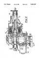
- FIG. 1is a sectional view of a device according to the present invention.
- FIG. 2is a sectional view of another embodiment of the present invention.
- FIG. 3is a partially sectional view of another embodiment of the present invention.
- FIG. 4is a sectional view of another embodiment of the present invention.
- FIG. 5is a sectional view of an arrangement of an adjustable motor similar to FIG. 4.
- FIG. 6is a sectional view of an arrangement of an adjustable motor similar to FIG. 4.
- FIG. 1a device according to the invention is shown with a multiple member drive housing 1 driven from a motor vehicle engine through a manual or automatic transmission propelled intake shaft 2.
- a first output shaft 3is formed unitarily with the input shaft 2.
- a second output shaft 4is parallel to the output shaft 3 in housing 1.
- the shaft 2, 3is supported in the housing 1 through two radial bearings 5 and 6.
- a beveled roller bearing 7acts with a further bearing (not shown) to mount the second output shaft 4.
- a clutch carrier 9is non rotatably arranged on the intake shaft 2 through a gear 8.
- the clutch carrier 9bears the outer disks of a friction clutch arrangement 10.
- a sleeve 13is rotatably mounted on the shaft 2 and 3 by needle bearings 11 and 12.
- the sleeveholds the inner disks of the clutch arrangement 10.
- the sleeve 13is further supported in the housing by two bevel roller bearings 14 and 15 which sit directly on the flanges of the gear wheel 16 on the sleeve 13.
- a spur gear 17is in engagement with the gear wheel 16.
- spur gear 17meshes with a gear wheel 18 on the shaft 4.
- the spur gear 17is mounted in two bevel roller bearings 19 and 20 which extend from a sleeve 21 set in the housing.
- An electrical adjustable motor 22is externally held on the housing.
- the motor shaft 23carries a drive pinion 24, which is in engagement with a gear wheel 25 with which it forms a reduction gear.
- the gear wheel 25is fastened to a shaft 26 which is mounted in the sleeve 21.
- the shaft 26penetrates the sleeve and carries a further gear wheel 27 on its opposing side.
- the gear wheel 27is in engagement with a support ring 28 which is rotatably mounted on the sleeve 13.
- the support ring 28is supported over an axial bearing on the sleeve 13.
- the support ring 28acts through balls 31 led in counterrotating ball grooves of varying depth on a pressure ring 30 over a radial pin 32.
- the pin 32engages an axial nut 33 of the housing 1 and thereby is held axially displaceable and non rotatingly across the housing 1.
- the pressure ring 30acts over an axial bearing 34 on the friction clutch arrangement 10 between sleeves 13 and clutch carrier 9.
- FIG. 2there is a device according to the present invention with a drive housing 41, an input shaft 42, coupled with a motor vehicle engine over a manual or automatic transmission, a first exit shaft 43, which is coupled through a gear 75, a second output shaft 44, and a clutch carrier 49 coupled with the output shaft 43.
- a sleeve 53is rotatably mounted on the shaft 42 in a needle bearing 52, which holds the inner flanges of the clutch arrangement 50.
- the sleeve 53is further mounted on needle bearing 51 on the shaft 42 and in a radial bearing 45.
- a gear wheel 56is coupled with the sleeve 53.
- a chain 57is in engagement with the gear wheel 56 and the gear wheel 58 on the shaft 44.
- the shaft 44is mounted in two radial bearings 59, 60.
- An electric adjustable motor 62is affixed externally with flanges on the drive housing.
- the motor shaft 63includes a drive pinion 64, which is in engagement with a gear wheel 65.
- the gear wheel 65is fastened on the shaft 66, mounted in a sleeve 61.
- the shaft 66penetrates the sleeve and has a second gear wheel 67 on its opposing side.
- the gear wheel 67is in engagement with a support ring 68 which is rotatably mounted on the sleeve 53 and is supported through an axial bearing 69 on the sleeve 53.
- the support ring 68operates over balls led in counterrotating ball grooves of varying depth on a pressure ring 70.
- An axial nut 73is provided which engages a radial pin 72 in the housing 41 and is consequently held axially displaceable and non rotatable across the housing 41.
- the pressure ring 70acts over an axial mounting 74 on a friction clutch arrangement 50 between the sleeve 53 and clutch carrier 49.
- FIG. 3a device according to the present invention is shown with a housing 81.
- the housing 81conjointly accepts a differential drive 131, while the corresponding power divider is situated separate from it in a common housing 116 with a shifting drive, which accepts a further differential drive 121.
- An input shaft 82 and a coaxial output shaft 84are mounted in the housing 81.
- the shaft 84is supported through two bevel bearing 85 and 86 in the housing 81.
- the input shaft 82is supported through a ball bearing 87 across the housing and over needle bearing 91 on the output shaft.
- the clutch carrier 89is fastened on the output shaft over a gear 88.
- the clutch carrier 89carries a first set of disks, while an inner sleeve 93 carries a second set of disks non rotatably bound with the input shaft 82.
- the disksare axially placed over the pins 113.
- Support rings 108supported in the housing, adjust intermediate disks (not individually shown) and axial bearings, acting over balls 111 on the pressure ring 110. Both rings are rotatably mounted on the sleeve 93.
- An adjustable motor 102 with shaft 103 including pinion 104is in rotatable drive connection with a gear wheel 105.
- the gear wheel 105is mounted on a shaft 106 which includes gear wheel 107 for transference.
- Gear wheel 107is in engagement with the support ring 108, which, by its adjustment, actuates adjustment of the transmission 90 through the paths for the balls.
- the pathshave varying depths throughout their periphery in both illustrated rings 108, 110.
- the drive of the input shaft 82results from the shift drive 116 over an intermediate wheel 122, which acts on an outer gear 117 of the outer shaft 83 which outer shaft is fashioned as a hollow shaft.
- This hollow shaftdirectly propels an anterior differential drive 121.
- a gear wheel 118 fastened on the hollow shaft 83is in engagement with a gear wheel 119 of an intermediate shaft 120.
- a bevel wheel 123is coupled with shaft 170 and is in engagement with a bevel wheel 124 on the shaft pin 125.
- a universal joint 126is affixed on the shaft pin 125 externally of the housing 116. The joint constantly drives an axial shaft. This is attached with the input shaft 82 of the housing 81 over a further universal joint 128.
- FIG. 4a device according to the invention is illustrated with a non unitary drive housing 141 in which an input shaft 142, driven by a motor vehicle engine via manual or automatic transmission, a first output shaft 143, which is non rotatingly affixed thereto, and a second output shaft 144, which is parallel to the shafts 142 and 143.
- the shafts 142 and 143are supported in the housing via radial bearings 146 and 147 and the second output shaft 144 by radial bearings 159 and 160.
- a clutch carrier 149is non rotatingly arranged on the output shaft 143 over a gear 148.
- the carrier 149carries the outer disks of a friction clutch arrangement 150.
- a sleeve 153is rotatably mounted on one side by a needle bearing 151 on the shaft 142 and on the other side of the housing 141 by bearing 145.
- the inner disks of the clutch arrangement 150are non rotatably arranged on the sleeve 153.
- the sleeve 153is unitarily formed with a gear wheel 156.
- a chain 157is in engagement with the gear wheel 156 and the gear wheel 158 on the shaft 144.
- An electrical adjustable motor 162is affixed to the drive housing 141.
- the motor shaft 163includes a drive pinion 164 which engages the gear wheel 165.
- the gear wheel 165is affixed to the shaft 166 which is mounted in the housing 141.
- the gear wheel 165is in engagement with a support ring 168 mounted rotatably to the sleeve 153.
- the support ring 168is supported on a ring 232 over an axial bearing 169 bound to the sleeve 153.
- the pressure ring 168works over balls 171 led counterrotatingly in ball grooves of varying depth on a pressure ring 170.
- An axial nut 173is the circumference of the ring in which a pin 172 radially engages it in the housing.
- the pressure ring 170is thereby held axially shiftable and non rotatably across the housing 141.
- the pressure ring 170acts on an axial bearing 174 and a ring 233 on the friction clutch arrangement 150 between the sleeve 153 and clutch carrier 149.
- the disks of the clutch arrangement 155are supported on a ring 234 axially on the sleeve 153.
- the shaft 142 and the shaft 143are sealed across the housing by gaskets 235 and 236, respectively.
- a flange 237is fastened with a screw nut 238 to the shaft 143.
- the shaft 144is sealed by means of a double gasket 239.
- a ventilation arrangement 240under which a baffle plate 241 is provided, are also shown. Outside the drive housing 141 an elastic suspension 242 is provided. An anterior shaft bearing 243 is recognizable on the shaft 163 of the adjustable motor 162. A further seal 259 is seen between the housing of the adjustable motor 162 and the drive housing 141.
- FIG. 5the same elements of FIG. 4 are identified with the same reference numerals. The difference is that a somewhat cylindrical flange 244 is provided on the drive housing 141. A cover 245 of the electric motor 162 is form-fitted and within and bolted onto the housing 141 with three circumferentially divided screws 246, one of which is visible. Further, a screw 247 is shown which is part of the connection of both halves of the housing 141. A disk shaped ball cage 260 is visible for the circumferentially divided support of the balls 171.
- FIG. 6the same elements are provided with the same reference numerals as in FIG. 4.
- a somewhat cylindrical flange 248is provided on the housing 141.
- the flange 248directly houses the stator coil 249 of the electric motor 162, of which further the detail of a rotor 250 is recognizable.
- the motor drive shaft 251is hereby inserted in a shaft pin 252 which includes a pinion 253.
- the pin 252is mounted by bearing 254 in the drive housing 141.
- the other end of the shaft 251 of the electric motoris mounted by bearing 255 in the cover 256.
- the cover 256is securely bolted on to the cylindrical housing flange 248 with three circumferentially divided screws 257, one of which is recognizable.
- a disk shaped ball cage 260 to circumferentially divide support of the ballsis likewise represented.
Landscapes
- Engineering & Computer Science (AREA)
- Chemical & Material Sciences (AREA)
- Combustion & Propulsion (AREA)
- Transportation (AREA)
- Mechanical Engineering (AREA)
- Arrangement And Driving Of Transmission Devices (AREA)
- Arrangement And Mounting Of Devices That Control Transmission Of Motive Force (AREA)
Abstract
Description
Claims (21)
Applications Claiming Priority (3)
| Application Number | Priority Date | Filing Date | Title |
|---|---|---|---|
| DE4004448 | 1990-02-14 | ||
| DE4004448.3 | 1990-02-14 | ||
| PCT/EP1991/000180WO1991012152A1 (en) | 1990-02-14 | 1991-01-31 | Device for switching on a drive train |
Publications (1)
| Publication Number | Publication Date |
|---|---|
| US5423235Atrue US5423235A (en) | 1995-06-13 |
Family
ID=6400066
Family Applications (1)
| Application Number | Title | Priority Date | Filing Date |
|---|---|---|---|
| US07/768,947Expired - LifetimeUS5423235A (en) | 1990-02-14 | 1991-01-31 | Device for switching on a drive train |
Country Status (5)
| Country | Link |
|---|---|
| US (1) | US5423235A (en) |
| EP (1) | EP0466863B1 (en) |
| JP (1) | JP2715340B2 (en) |
| DE (1) | DE59100153D1 (en) |
| WO (1) | WO1991012152A1 (en) |
Cited By (59)
| Publication number | Priority date | Publication date | Assignee | Title |
|---|---|---|---|---|
| US6286620B1 (en)* | 2000-05-30 | 2001-09-11 | Deere & Company | Access plate for an axle of a differentially steered vehicle |
| US20030029690A1 (en)* | 2001-07-31 | 2003-02-13 | Karl Reisinger | Power-split transmission with a controllable friction clutch |
| US6675677B2 (en)* | 2002-04-12 | 2004-01-13 | New Venture Gear, Inc. | Transfer case with multi-gear transfer mechanism |
| US6698565B2 (en) | 2002-08-02 | 2004-03-02 | Visteon Global Technologies, Inc. | Selectively engageable differential |
| US6711968B2 (en) | 2002-08-02 | 2004-03-30 | Visteon Global Technologies, Inc. | Axle differential assembly |
| US6745879B1 (en) | 2003-02-03 | 2004-06-08 | New Venture Gear, Inc. | Hydromechanical coupling with clutch assembly and magnetorheological clutch actuator |
| US6766889B1 (en) | 2003-02-11 | 2004-07-27 | New Venture Gear, Inc. | Wedge fork clutch actuator for driveline clutches |
| US20040163919A1 (en)* | 2003-02-21 | 2004-08-26 | Kirkwood Malcolm E. | Torque transfer device with double ball screw clutch actuator |
| US20040163920A1 (en)* | 2003-02-20 | 2004-08-26 | Unal Gazyakan | Transfer case with controllable clutch |
| US20040163921A1 (en)* | 2003-02-20 | 2004-08-26 | Claus Granzow | Distributor gear with adjustable coupling |
| US20040173428A1 (en)* | 2003-03-07 | 2004-09-09 | Bowen Thomas C. | Worm driven ball screw actuator for traction clutches |
| US20040188216A1 (en)* | 2003-03-27 | 2004-09-30 | Nobushi Yamazaki | Torque transmission apparatus |
| US20040200655A1 (en)* | 2003-04-08 | 2004-10-14 | Mueller Joseph G. | On-demand transfer case |
| US6805653B2 (en) | 2002-08-02 | 2004-10-19 | Visteon Global Technologies, Inc. | Selectively controlled limited slip differential |
| US20040231944A1 (en)* | 2003-02-03 | 2004-11-25 | Dolan James P. | Power transmission device for a four-wheel drive vehicle |
| US20050096172A1 (en)* | 2003-10-30 | 2005-05-05 | Mueller Joseph G. | Two-speed transfer case with adaptive clutch control |
| EP1529675A2 (en) | 2003-11-07 | 2005-05-11 | New Venture Gear, Inc. | Control strategy for active torque control |
| US20050113203A1 (en)* | 2003-11-24 | 2005-05-26 | Mueller Joseph G. | Clutch actuation system for two-speed active transfer case |
| US20050159264A1 (en)* | 2003-03-07 | 2005-07-21 | Dumitru Puiu | Torque vectoring drive units with worm driven ball screw clutches |
| US20050160728A1 (en)* | 2004-01-22 | 2005-07-28 | Dumitru Puiu | Transfer case with electrohydraulic clutch actuator |
| US20050167223A1 (en)* | 2004-01-30 | 2005-08-04 | Dumitru Puiu | Hydraulically-actuated pilot clutch type clutch assembly |
| US20050167224A1 (en)* | 2004-02-04 | 2005-08-04 | Dumitru Puiu | Active torque coupling with hydraulically-actuated ball ramp clutch assembly |
| US20050205375A1 (en)* | 2003-02-03 | 2005-09-22 | Magna Drivetrain Of America, Inc. | Torque transfer coupling with magnetorheological clutch actuator |
| DE10311427B4 (en)* | 2002-03-22 | 2005-11-24 | Gkn Technology Ltd., Wolverhampton | differential gear |
| US20050279601A1 (en)* | 2004-06-17 | 2005-12-22 | Thomas Tuday | Torque-transmitting mechanisms for a planetary transmission |
| US20060046888A1 (en)* | 2004-08-30 | 2006-03-02 | Dumitru Puiu | Torque coupling with power-operated clutch actuator |
| US20060081437A1 (en)* | 2004-10-19 | 2006-04-20 | Dumitru Puiu | Torque transfer mechanisms for power-operated clutch actuator |
| WO2006044991A2 (en) | 2004-10-19 | 2006-04-27 | Magna Powertrain Usa, Inc. | Torque transfer mechanisms with power-operated clutch actuator |
| US20060128515A1 (en)* | 2003-11-24 | 2006-06-15 | Mueller Joseph G | Two-speed transfer case |
| US20060163018A1 (en)* | 2005-01-26 | 2006-07-27 | Todd Ekonen | Power-operated clutch actuator for torque transfer mechanisms |
| US20060254845A1 (en)* | 2005-05-12 | 2006-11-16 | Detlef Baasch | Apparatus and procedure for the adjustment of a friction shifting element capability |
| US20070023252A1 (en)* | 2005-07-28 | 2007-02-01 | Magna Powertrain Usa, Inc. | Power-operated clutch actuator for torque couplings |
| US20070049451A1 (en)* | 2005-09-01 | 2007-03-01 | Magna Powertrain Usa, Inc. | Two-speed transfer case with ballramp clutch actuator |
| US20070087890A1 (en)* | 2005-10-14 | 2007-04-19 | Team Industries, Inc. | Differential |
| US20070095628A1 (en)* | 2005-10-28 | 2007-05-03 | Magna Powertrain Usa, Inc. | Power-operated clutch actuator for torque transfer mechanisms |
| US20070151823A1 (en)* | 2003-09-05 | 2007-07-05 | Georg Kwoka | Compact drive assembly with multi-plate coupling |
| US20070186690A1 (en)* | 2005-10-26 | 2007-08-16 | Theodor Gassmann | Assembly for determining torque at a friction coupling |
| US20070189965A1 (en)* | 2004-06-17 | 2007-08-16 | Kuperus John H | Copper-complex isonitrile positron emission tomography (pet) imaging agent and method |
| US20070251345A1 (en)* | 2006-04-26 | 2007-11-01 | Magna Powertrain Ag & Co Kg | Two-Speed Transfer Case With Adaptive Torque Transfer Clutch |
| US20080004783A1 (en)* | 2006-06-19 | 2008-01-03 | Magna Powertrain Usa, Inc. | Dynamic Traction Control System |
| US20080129230A1 (en)* | 2005-01-13 | 2008-06-05 | Zf Friedrichshafen Ag | Vehicle Gearbox With An Integrated Electric Motor |
| US20080149451A1 (en)* | 2006-12-20 | 2008-06-26 | Borgwarner Inc. | Clutch device utilizing brushless motor |
| US20090032352A1 (en)* | 2007-08-02 | 2009-02-05 | Borgwarner Inc. | Motor actuated range shift and on demand 4wd |
| US20090212649A1 (en)* | 2008-02-26 | 2009-08-27 | Gm Global Technology Operations, Inc. | Electric motor assembly with stator mounted in vehicle powertrain housing and method |
| US20100012455A1 (en)* | 2005-04-28 | 2010-01-21 | Magna Powertrain Ag & Co. Kg | Power divider for motor vehicles comprising a controlled friction coupling |
| US7650808B2 (en) | 2006-02-03 | 2010-01-26 | Magna Powertrain Usa, Inc. | Sprial cam clutch actuation system for two-speed transfer case |
| US20110179906A1 (en)* | 2008-08-15 | 2011-07-28 | Peter Juenemann | Drive assembly for a motor vehicle driven by a plurality of axles |
| WO2011149903A1 (en) | 2010-05-25 | 2011-12-01 | Magna Powertrain Of America, Inc. | Torque transfer device for a motor vehicle comprising an electromagnetic actuation system with force feedback control using piezoelectric ring and method for controlling a respective actuation system |
| WO2011149905A1 (en) | 2010-05-25 | 2011-12-01 | Magna Powertrain Of America, Inc. | Torque transfer device for a motor vehicle comprising an electromagnetic actuator position control system and method for controlling a respective position control system |
| US8584785B2 (en) | 2008-08-14 | 2013-11-19 | American Axle & Manufacturing, Inc. | Motor vehicle with disconnectable all-wheel drive system |
| US8668615B2 (en) | 2008-12-19 | 2014-03-11 | Gkn Driveline International Gmbh | Drive assembly with hydraulic actuating mechanism |
| US8678971B2 (en) | 2008-12-19 | 2014-03-25 | Gkn Driveline International Gmbh | Drive assembly |
| US8986148B2 (en) | 2012-10-05 | 2015-03-24 | American Axle & Manufacturing, Inc. | Single speed and two-speed disconnecting axle arrangements |
| DE102014223559A1 (en) | 2013-11-20 | 2015-05-21 | Magna Powertrain Of America, Inc. | ELECTROMAGNETIC COUPLING |
| DE102014223968A1 (en) | 2013-11-26 | 2015-05-28 | Magna Powertrain Of America, Inc. | Torque transfer mechanism with dense ball ramp clutch actuator unit |
| US9079495B2 (en) | 2012-06-15 | 2015-07-14 | American Axle & Manufacturing, Inc. | Disconnectable driveline with a multi-speed RDM and PTU |
| US10704663B2 (en) | 2018-09-06 | 2020-07-07 | American Axle & Manufacturing, Inc. | Modular disconnecting drive module with torque vectoring augmentation |
| WO2020210888A1 (en)* | 2019-04-17 | 2020-10-22 | CNH Industrial Brasil Ltda. | Disengagement system for a vehicle with a first shaft and a second shaft |
| US10927937B2 (en) | 2018-09-06 | 2021-02-23 | American Axle & Manufacturing, Inc. | Modular disconnecting drive module with torque vectoring augmentation |
Families Citing this family (8)
| Publication number | Priority date | Publication date | Assignee | Title |
|---|---|---|---|---|
| AT5722U1 (en) | 2001-09-18 | 2002-10-25 | Steyr Powertrain Ag & Co Kg | DEVICE AND METHOD FOR ADJUSTING THE TORQUE TRANSMITTED BY A FRICTION CLUTCH |
| DE10304730B3 (en)* | 2003-02-06 | 2004-10-07 | Gkn Driveline International Gmbh | Lamella coupling used as a friction coupling comprises a coupling hub with axially moving inner lamellae, and a coupling basket with axially moving outer lamellae |
| DE102004015304A1 (en) | 2003-03-31 | 2004-10-21 | Tochigi Fuji Sangyo K.K. | Torque transfer clutch |
| DE102004004931A1 (en)* | 2004-01-31 | 2005-08-25 | Gkn Driveline International Gmbh | Multi-disc clutch with conical blades |
| AT7553U1 (en) | 2004-02-23 | 2005-05-25 | Magna Drivetrain Ag & Co Kg | DRIVE TRAIN OF A ALL-ROAD GEARED VEHICLE |
| DE112004002908B4 (en)* | 2004-09-25 | 2010-06-02 | Gkn Driveline International Gmbh | Locking arrangement with adjustment by magnetorheological fluid |
| DE102005051500B3 (en)* | 2005-10-26 | 2007-07-05 | Gkn Driveline International Gmbh | Determining torque acting on multi-plate friction clutch in vehicle, includes force measurement system within clutch casing, acted upon by plate carrier stud when clutch is operated |
| DE102008037885B4 (en) | 2008-08-15 | 2020-08-06 | Gkn Automotive Limited | Coupling arrangement and drive train arrangement for a multi-axle motor vehicle |
Citations (10)
| Publication number | Priority date | Publication date | Assignee | Title |
|---|---|---|---|---|
| GB2008694A (en)* | 1977-11-23 | 1979-06-06 | Hurth Verwaltungs Gmbh | Friction Clutch, more particularly Plate Clutch Operated by Servo Action |
| US4805486A (en)* | 1986-06-04 | 1989-02-21 | Tochigifujisangyo Kabushiki Kaisha | Locking differential gear assembly |
| US4883138A (en)* | 1987-04-27 | 1989-11-28 | Mazda Motor Corporation | Four-wheel drive vehicle operating system |
| US4895236A (en)* | 1987-02-02 | 1990-01-23 | Aisin-Warner Kabushiki Kaisha | Actuator for the frictional engaging device |
| DE3915959A1 (en)* | 1989-05-18 | 1990-11-22 | Gkn Automotive Ag | GEARBOX |
| US5076112A (en)* | 1991-04-19 | 1991-12-31 | New Venture Gear, Inc. | Easy shift sector for transfer case |
| US5150637A (en)* | 1988-11-18 | 1992-09-29 | Mazda Motor Corporation | Transfer case shifting apparatus for four wheel drive vehicle |
| US5199325A (en)* | 1991-09-12 | 1993-04-06 | Dana Corporation | Electronic shift or clutch actuator for a vehicle transmission |
| US5271478A (en)* | 1990-02-27 | 1993-12-21 | Mazda Motor Corporation | Power transmitting system |
| US5323871A (en)* | 1993-03-10 | 1994-06-28 | New Venture Gear, Inc. | Rotary actuation mechanism for torque modulated transfer case |
- 1991
- 1991-01-31WOPCT/EP1991/000180patent/WO1991012152A1/enactiveIP Right Grant
- 1991-01-31EPEP91902942Apatent/EP0466863B1/ennot_activeExpired - Lifetime
- 1991-01-31USUS07/768,947patent/US5423235A/ennot_activeExpired - Lifetime
- 1991-01-31DEDE9191902942Tpatent/DE59100153D1/ennot_activeExpired - Fee Related
- 1991-01-31JPJP3503097Apatent/JP2715340B2/ennot_activeExpired - Fee Related
Patent Citations (10)
| Publication number | Priority date | Publication date | Assignee | Title |
|---|---|---|---|---|
| GB2008694A (en)* | 1977-11-23 | 1979-06-06 | Hurth Verwaltungs Gmbh | Friction Clutch, more particularly Plate Clutch Operated by Servo Action |
| US4805486A (en)* | 1986-06-04 | 1989-02-21 | Tochigifujisangyo Kabushiki Kaisha | Locking differential gear assembly |
| US4895236A (en)* | 1987-02-02 | 1990-01-23 | Aisin-Warner Kabushiki Kaisha | Actuator for the frictional engaging device |
| US4883138A (en)* | 1987-04-27 | 1989-11-28 | Mazda Motor Corporation | Four-wheel drive vehicle operating system |
| US5150637A (en)* | 1988-11-18 | 1992-09-29 | Mazda Motor Corporation | Transfer case shifting apparatus for four wheel drive vehicle |
| DE3915959A1 (en)* | 1989-05-18 | 1990-11-22 | Gkn Automotive Ag | GEARBOX |
| US5271478A (en)* | 1990-02-27 | 1993-12-21 | Mazda Motor Corporation | Power transmitting system |
| US5076112A (en)* | 1991-04-19 | 1991-12-31 | New Venture Gear, Inc. | Easy shift sector for transfer case |
| US5199325A (en)* | 1991-09-12 | 1993-04-06 | Dana Corporation | Electronic shift or clutch actuator for a vehicle transmission |
| US5323871A (en)* | 1993-03-10 | 1994-06-28 | New Venture Gear, Inc. | Rotary actuation mechanism for torque modulated transfer case |
Cited By (144)
| Publication number | Priority date | Publication date | Assignee | Title |
|---|---|---|---|---|
| US6286620B1 (en)* | 2000-05-30 | 2001-09-11 | Deere & Company | Access plate for an axle of a differentially steered vehicle |
| US20030029690A1 (en)* | 2001-07-31 | 2003-02-13 | Karl Reisinger | Power-split transmission with a controllable friction clutch |
| US6651793B2 (en)* | 2001-07-31 | 2003-11-25 | Steyr Powertrain Ag & Co Ag | Power-split transmission with a controllable friction clutch |
| DE10311427B4 (en)* | 2002-03-22 | 2005-11-24 | Gkn Technology Ltd., Wolverhampton | differential gear |
| US20040139819A1 (en)* | 2002-04-12 | 2004-07-22 | Gareth Thomas | Transfer case with multi-gear transfer mechanism |
| US6931964B2 (en) | 2002-04-12 | 2005-08-23 | Magna Drivetrain Of America, Inc. | Transfer case with multi-gear transfer mechanism |
| WO2003086803A3 (en)* | 2002-04-12 | 2004-06-10 | New Venture Gear Inc | Transfer case with multi-gear transfer mechanism |
| US6675677B2 (en)* | 2002-04-12 | 2004-01-13 | New Venture Gear, Inc. | Transfer case with multi-gear transfer mechanism |
| US6805653B2 (en) | 2002-08-02 | 2004-10-19 | Visteon Global Technologies, Inc. | Selectively controlled limited slip differential |
| US6711968B2 (en) | 2002-08-02 | 2004-03-30 | Visteon Global Technologies, Inc. | Axle differential assembly |
| US6698565B2 (en) | 2002-08-02 | 2004-03-02 | Visteon Global Technologies, Inc. | Selectively engageable differential |
| US7083030B2 (en) | 2003-02-03 | 2006-08-01 | Magna Drivertrain Of America, Inc. | Torque transfer coupling with magnetorheological clutch actuator |
| US6932204B2 (en) | 2003-02-03 | 2005-08-23 | Magna Drivetrain Of America, Inc. | Power transmission device for a four-wheel drive vehicle |
| US20040231944A1 (en)* | 2003-02-03 | 2004-11-25 | Dolan James P. | Power transmission device for a four-wheel drive vehicle |
| US20040168875A1 (en)* | 2003-02-03 | 2004-09-02 | Dolan James P. | Hydromechanical coupling with clutch assembly and magnetorheological clutch actuator |
| US6811007B2 (en) | 2003-02-03 | 2004-11-02 | New Venture Gear, Inc. | Hydromechanical coupling with clutch assembly and magnetorheological clutch actuator |
| US6988602B2 (en) | 2003-02-03 | 2006-01-24 | Magna Powertrain, Inc. | Torque transfer coupling with magnetorheological clutch actuator |
| US20050205375A1 (en)* | 2003-02-03 | 2005-09-22 | Magna Drivetrain Of America, Inc. | Torque transfer coupling with magnetorheological clutch actuator |
| US6745879B1 (en) | 2003-02-03 | 2004-06-08 | New Venture Gear, Inc. | Hydromechanical coupling with clutch assembly and magnetorheological clutch actuator |
| US20040188213A1 (en)* | 2003-02-11 | 2004-09-30 | Pennycuff Dale L. | Wedge fork clutch actuator for driveline clutches |
| US6938748B2 (en) | 2003-02-11 | 2005-09-06 | Magna Drivetrain Of America, Inc. | Wedge fork clutch actuator for driveline clutches |
| US6766889B1 (en) | 2003-02-11 | 2004-07-27 | New Venture Gear, Inc. | Wedge fork clutch actuator for driveline clutches |
| US20040163921A1 (en)* | 2003-02-20 | 2004-08-26 | Claus Granzow | Distributor gear with adjustable coupling |
| US20040163920A1 (en)* | 2003-02-20 | 2004-08-26 | Unal Gazyakan | Transfer case with controllable clutch |
| US7040472B2 (en)* | 2003-02-20 | 2006-05-09 | Zf Friedrichshafen Ag | Transfer case with controllable clutch |
| US7021441B2 (en)* | 2003-02-20 | 2006-04-04 | Zf Friedrichshafen Ag | Distributor gear with adjustable coupling |
| US6808053B2 (en) | 2003-02-21 | 2004-10-26 | New Venture Gear, Inc. | Torque transfer device having an electric motor/brake actuator and friction clutch |
| US6808052B2 (en) | 2003-02-21 | 2004-10-26 | New Venture Gear, Inc. | Torque transfer device with double ball screw clutch actuator |
| US6945375B2 (en) | 2003-02-21 | 2005-09-20 | Magna Drivetrain Of America, Inc. | Torque transfer device having an electric motor/brake actuator and friction clutch |
| US20040163918A1 (en)* | 2003-02-21 | 2004-08-26 | Kirkwood Malcolm E. | Torque transfer device having an electric motor/brake actuator and friction clutch |
| US20050079943A1 (en)* | 2003-02-21 | 2005-04-14 | Kirkwood Malcolm E. | Torque transfer device having an electric motor/brake actuator and friction clutch |
| US20040163919A1 (en)* | 2003-02-21 | 2004-08-26 | Kirkwood Malcolm E. | Torque transfer device with double ball screw clutch actuator |
| US7175558B2 (en) | 2003-03-07 | 2007-02-13 | Magna Powertrain Usa, Inc. | Torque vectoring drive units with worm driven ball screw clutches |
| US20050159264A1 (en)* | 2003-03-07 | 2005-07-21 | Dumitru Puiu | Torque vectoring drive units with worm driven ball screw clutches |
| US6851537B2 (en) | 2003-03-07 | 2005-02-08 | Magna Drivetrain Of America, Inc. | Worm driven ball screw actuator for traction clutches |
| US20040173428A1 (en)* | 2003-03-07 | 2004-09-09 | Bowen Thomas C. | Worm driven ball screw actuator for traction clutches |
| US7083033B2 (en)* | 2003-03-27 | 2006-08-01 | Tochigi Fuji Sangyo Kabushiki Kaisha | Torque transmission apparatus |
| US20040188216A1 (en)* | 2003-03-27 | 2004-09-30 | Nobushi Yamazaki | Torque transmission apparatus |
| EP1466777A3 (en)* | 2003-04-08 | 2005-06-08 | New Venture Gear, Inc. | On-demand transfer case |
| US7178652B2 (en) | 2003-04-08 | 2007-02-20 | Magna Powertrain Usa, Inc. | Power transmission device having torque transfer mechanism with power-operated clutch actuator |
| US20060054373A1 (en)* | 2003-04-08 | 2006-03-16 | Mueller Joseph G | Power transmission device having torque transfer mechanism with power-operated clutch actuator |
| US20050023063A1 (en)* | 2003-04-08 | 2005-02-03 | Mueller Joseph G. | On-demand transfer case |
| US6808037B1 (en) | 2003-04-08 | 2004-10-26 | New Venture Gear, Inc. | On-demand transfer case |
| US20040200655A1 (en)* | 2003-04-08 | 2004-10-14 | Mueller Joseph G. | On-demand transfer case |
| US6964315B2 (en) | 2003-04-08 | 2005-11-15 | Magnadrivetrain Of America, Inc. | On-demand transfer case |
| US20070151823A1 (en)* | 2003-09-05 | 2007-07-05 | Georg Kwoka | Compact drive assembly with multi-plate coupling |
| US7648011B2 (en) | 2003-09-05 | 2010-01-19 | Gkn Driveline International Gmbh | Compact drive assembly with multi-plate coupling |
| US20050096172A1 (en)* | 2003-10-30 | 2005-05-05 | Mueller Joseph G. | Two-speed transfer case with adaptive clutch control |
| US7081064B2 (en) | 2003-10-30 | 2006-07-25 | Magna Powertrain Usa, Inc. | Two-speed transfer case with adaptive clutch control |
| US7229378B2 (en) | 2003-10-30 | 2007-06-12 | Magna Powertrain Usa, Inc. | Shift system for transfer case |
| US20060247082A1 (en)* | 2003-10-30 | 2006-11-02 | Magna Powertrain Usa, Inc. | Shift system for transfer case |
| US6905436B2 (en) | 2003-10-30 | 2005-06-14 | Magna Drivetrain Of America, Inc. | Two-speed transfer case with adaptive clutch control |
| US20050101438A1 (en)* | 2003-11-07 | 2005-05-12 | Brent Cring | Control strategy for active torque control |
| US7611441B2 (en) | 2003-11-07 | 2009-11-03 | Magna Powertrain Usa, Inc. | Torque transfer control system for power transmission device in a motor vehicle |
| EP1529675A2 (en) | 2003-11-07 | 2005-05-11 | New Venture Gear, Inc. | Control strategy for active torque control |
| US7445581B2 (en) | 2003-11-07 | 2008-11-04 | Magna Powertrain Usa, Inc. | Control strategy for active torque control |
| US7125364B2 (en) | 2003-11-07 | 2006-10-24 | Magna Powertrain Usa, Inc. | Control strategy for active torque control |
| US20070037662A1 (en)* | 2003-11-07 | 2007-02-15 | Brent Cring | Control strategy for active torque control |
| US6929577B2 (en) | 2003-11-24 | 2005-08-16 | Magna Drivetrain Of America, Inc. | Clutch actuation system for two-speed active transfer case |
| US20050113203A1 (en)* | 2003-11-24 | 2005-05-26 | Mueller Joseph G. | Clutch actuation system for two-speed active transfer case |
| US7033300B2 (en) | 2003-11-24 | 2006-04-25 | Magna Powertrain, Inc. | Clutch actuation system for two-speed active transfer case |
| US20050202919A1 (en)* | 2003-11-24 | 2005-09-15 | Mueller Joseph G. | Clutch actuation system for two-speed active transfer case |
| US20060128515A1 (en)* | 2003-11-24 | 2006-06-15 | Mueller Joseph G | Two-speed transfer case |
| US7399251B2 (en) | 2003-11-24 | 2008-07-15 | Magna Powertrain Usa, Inc. | Two-speed transfer case |
| US20060065070A1 (en)* | 2004-01-22 | 2006-03-30 | Dumitru Puiu | Power transmission device with electrohydraulic clutch actuator |
| US7004873B2 (en) | 2004-01-22 | 2006-02-28 | Magna Powertrain, Inc. | Transfer case with electrohydraulic clutch actuator |
| US20050160728A1 (en)* | 2004-01-22 | 2005-07-28 | Dumitru Puiu | Transfer case with electrohydraulic clutch actuator |
| US7278943B2 (en) | 2004-01-22 | 2007-10-09 | Magna Powertrain Usa, Inc. | Power transmission device with electrohydraulic clutch actuator |
| US20050167223A1 (en)* | 2004-01-30 | 2005-08-04 | Dumitru Puiu | Hydraulically-actuated pilot clutch type clutch assembly |
| US6991079B2 (en) | 2004-01-30 | 2006-01-31 | Magna Powertrain, Inc. | Power transfer device with hydraulically-actuated clutch assembly |
| US6948604B2 (en) | 2004-01-30 | 2005-09-27 | Magna Drivetrain Of America, Inc. | Hydraulically-actuated pilot clutch type clutch assembly |
| US20050230213A1 (en)* | 2004-01-30 | 2005-10-20 | Dumitru Puiu | Power transfer device with hydraulically-actuated clutch assembly |
| US20050167224A1 (en)* | 2004-02-04 | 2005-08-04 | Dumitru Puiu | Active torque coupling with hydraulically-actuated ball ramp clutch assembly |
| US6945374B2 (en) | 2004-02-04 | 2005-09-20 | Magna Drivetrain Of America, Inc. | Active torque coupling with hydraulically-actuated ball ramp clutch assembly |
| US20050230214A1 (en)* | 2004-02-04 | 2005-10-20 | Dumitru Puiu | Power transmission devices with active torque couplings |
| US7281617B2 (en) | 2004-02-04 | 2007-10-16 | Magna Powertrain Usa, Inc. | Active torque coupling with hydraulically-actuated rotary clutch actuator |
| US20060000685A1 (en)* | 2004-02-04 | 2006-01-05 | Dumitru Puiu | Active torque coupling with hydraulically-actuated rotary clutch actuator |
| US6991080B2 (en) | 2004-02-04 | 2006-01-31 | Magna Powertrain, Inc. | Power transmission devices with active torque couplings |
| US20070189965A1 (en)* | 2004-06-17 | 2007-08-16 | Kuperus John H | Copper-complex isonitrile positron emission tomography (pet) imaging agent and method |
| US20050279601A1 (en)* | 2004-06-17 | 2005-12-22 | Thomas Tuday | Torque-transmitting mechanisms for a planetary transmission |
| US20060046888A1 (en)* | 2004-08-30 | 2006-03-02 | Dumitru Puiu | Torque coupling with power-operated clutch actuator |
| US7338403B2 (en) | 2004-08-30 | 2008-03-04 | Magna Powertrain Usa, Inc. | Torque coupling with power-operated clutch actuator |
| US7337886B2 (en) | 2004-10-19 | 2008-03-04 | Magna Powertrain Usa, Inc. | Torque transfer mechanisms with power-operated clutch actuator |
| WO2006044991A2 (en) | 2004-10-19 | 2006-04-27 | Magna Powertrain Usa, Inc. | Torque transfer mechanisms with power-operated clutch actuator |
| US7201265B2 (en) | 2004-10-19 | 2007-04-10 | Magna Powertrain Usa, Inc. | Torque transfer mechanism with power-operated clutch actuator |
| US7201264B2 (en) | 2004-10-19 | 2007-04-10 | Magna Powertrain Usa, Inc. | Torque transfer mechanisms for power-operated clutch actuator |
| US20060081437A1 (en)* | 2004-10-19 | 2006-04-20 | Dumitru Puiu | Torque transfer mechanisms for power-operated clutch actuator |
| US20060278489A1 (en)* | 2004-10-19 | 2006-12-14 | Magna Powertrain Usa, Inc. | Torque transfer mechanism with power-operated clutch actuator |
| US20070158160A1 (en)* | 2004-10-19 | 2007-07-12 | Magna Powertrain Usa, Inc. | Torque transfer mechanisms with power-operated clutch actuator |
| US7798032B2 (en) | 2005-01-13 | 2010-09-21 | Zf Friedrichshafen Ag | Vehicle gearbox with an integrated electric motor |
| US20080129230A1 (en)* | 2005-01-13 | 2008-06-05 | Zf Friedrichshafen Ag | Vehicle Gearbox With An Integrated Electric Motor |
| US20060163018A1 (en)* | 2005-01-26 | 2006-07-27 | Todd Ekonen | Power-operated clutch actuator for torque transfer mechanisms |
| US7258213B2 (en) | 2005-01-26 | 2007-08-21 | Magna Powertrain Usa, Inc. | Power transmission devices having torque transfer coupling with power-operated clutch actuator |
| US7111716B2 (en) | 2005-01-26 | 2006-09-26 | Magna Powertrain Usa, Inc. | Power-operated clutch actuator for torque transfer mechanisms |
| US20060272876A1 (en)* | 2005-01-26 | 2006-12-07 | Magna Powertrain Usa, Inc. | Power transmission devices having torque transfer coupling with power-operated clutch actuator |
| WO2006081108A2 (en) | 2005-01-26 | 2006-08-03 | Magna Drivetrain Of America, Inc. | Power-operated clutch actuator for torque transfer mechanisms |
| US20100012455A1 (en)* | 2005-04-28 | 2010-01-21 | Magna Powertrain Ag & Co. Kg | Power divider for motor vehicles comprising a controlled friction coupling |
| US8091451B2 (en) | 2005-04-28 | 2012-01-10 | Magna Powertrain Ag & Co Kg | Power divider for motor vehicles comprising a controlled friction coupling |
| US20060254845A1 (en)* | 2005-05-12 | 2006-11-16 | Detlef Baasch | Apparatus and procedure for the adjustment of a friction shifting element capability |
| US20070023252A1 (en)* | 2005-07-28 | 2007-02-01 | Magna Powertrain Usa, Inc. | Power-operated clutch actuator for torque couplings |
| US7686149B2 (en) | 2005-07-28 | 2010-03-30 | Magna Powertrain Usa, Inc. | Power transmission device with friction clutch and power-operated clutch actuator |
| US20090211869A1 (en)* | 2005-07-28 | 2009-08-27 | Magna Powertrain Usa, Inc. | Power Transmission Device With Friction Clutch And Power-Operated Clutch Actuator |
| US7527133B2 (en) | 2005-07-28 | 2009-05-05 | Magna Powertrain Usa, Inc. | Power-operated clutch actuator for torque couplings |
| WO2007016383A3 (en)* | 2005-07-28 | 2007-10-11 | Magna Powertrain Usa Inc | Power-operated clutch actuator for torque couplings |
| US7540820B2 (en) | 2005-09-01 | 2009-06-02 | Magna Powertrain Usa, Inc. | Two-speed transfer case with ballramp clutch actuator |
| US20070049451A1 (en)* | 2005-09-01 | 2007-03-01 | Magna Powertrain Usa, Inc. | Two-speed transfer case with ballramp clutch actuator |
| WO2007047064A3 (en)* | 2005-10-14 | 2007-08-02 | Team Ind Inc | Differential |
| US20070087890A1 (en)* | 2005-10-14 | 2007-04-19 | Team Industries, Inc. | Differential |
| US7278945B2 (en) | 2005-10-14 | 2007-10-09 | Team Industries, Inc. | Differential |
| US7698960B2 (en) | 2005-10-26 | 2010-04-20 | Gkn Driveline International Gmbh | Assembly for determining torque at a friction coupling |
| US20070186690A1 (en)* | 2005-10-26 | 2007-08-16 | Theodor Gassmann | Assembly for determining torque at a friction coupling |
| US20070095628A1 (en)* | 2005-10-28 | 2007-05-03 | Magna Powertrain Usa, Inc. | Power-operated clutch actuator for torque transfer mechanisms |
| US7650808B2 (en) | 2006-02-03 | 2010-01-26 | Magna Powertrain Usa, Inc. | Sprial cam clutch actuation system for two-speed transfer case |
| US20070251345A1 (en)* | 2006-04-26 | 2007-11-01 | Magna Powertrain Ag & Co Kg | Two-Speed Transfer Case With Adaptive Torque Transfer Clutch |
| US7694598B2 (en) | 2006-04-26 | 2010-04-13 | Magna Powertrain Ag & Co Kg | Two-speed transfer case with adaptive torque transfer clutch |
| US7491145B2 (en)* | 2006-06-19 | 2009-02-17 | Magna Powertrain Usa, Inc. | Dynamic traction control system |
| US20090082934A1 (en)* | 2006-06-19 | 2009-03-26 | Magna Powertrain Usa, Inc. | Power Transfer Assembly With Torque Sensors And Torque Control System |
| US7813857B2 (en) | 2006-06-19 | 2010-10-12 | Magna Powertrain Usa, Inc. | Power transfer assembly with torque sensors and torque control system |
| US20080004783A1 (en)* | 2006-06-19 | 2008-01-03 | Magna Powertrain Usa, Inc. | Dynamic Traction Control System |
| US20080149451A1 (en)* | 2006-12-20 | 2008-06-26 | Borgwarner Inc. | Clutch device utilizing brushless motor |
| US7896146B2 (en) | 2006-12-20 | 2011-03-01 | Borgwarner, Inc. | Clutch device utilizing brushless motor |
| US20090032352A1 (en)* | 2007-08-02 | 2009-02-05 | Borgwarner Inc. | Motor actuated range shift and on demand 4wd |
| US7847444B2 (en)* | 2008-02-26 | 2010-12-07 | Gm Global Technology Operations, Inc. | Electric motor assembly with stator mounted in vehicle powertrain housing and method |
| US20090212649A1 (en)* | 2008-02-26 | 2009-08-27 | Gm Global Technology Operations, Inc. | Electric motor assembly with stator mounted in vehicle powertrain housing and method |
| US8584785B2 (en) | 2008-08-14 | 2013-11-19 | American Axle & Manufacturing, Inc. | Motor vehicle with disconnectable all-wheel drive system |
| US10160314B2 (en) | 2008-08-14 | 2018-12-25 | American Axle & Manufacturing, Inc. | Motor vehicle with disconnectable all-wheel drive system |
| US9493069B2 (en) | 2008-08-14 | 2016-11-15 | American Axle & Manufacturing, Inc. | Motor vehicle with disconnectable all-wheel drive system |
| US20110179906A1 (en)* | 2008-08-15 | 2011-07-28 | Peter Juenemann | Drive assembly for a motor vehicle driven by a plurality of axles |
| US8668615B2 (en) | 2008-12-19 | 2014-03-11 | Gkn Driveline International Gmbh | Drive assembly with hydraulic actuating mechanism |
| US8678971B2 (en) | 2008-12-19 | 2014-03-25 | Gkn Driveline International Gmbh | Drive assembly |
| WO2011149903A1 (en) | 2010-05-25 | 2011-12-01 | Magna Powertrain Of America, Inc. | Torque transfer device for a motor vehicle comprising an electromagnetic actuation system with force feedback control using piezoelectric ring and method for controlling a respective actuation system |
| GB2494591A (en)* | 2010-05-25 | 2013-03-13 | Magna Powertrain America Inc | Torque transfer device for a motor vehicle comprising an electromagnetic actuation system with force feedback control using piezoelectric ring and method |
| DE112011101785T5 (en) | 2010-05-25 | 2013-06-13 | Magna Powertrain Of America, Inc. | A torque transmitting device for a motor vehicle having a position control system for an electromagnetic actuator and method for controlling a corresponding position control system |
| US8777814B2 (en) | 2010-05-25 | 2014-07-15 | Timothy M. Burns | Torque transfer device for a motor vehicle comprising an electromagnetic actuator position control system and method for controlling a respective position control system |
| DE112011101784T5 (en) | 2010-05-25 | 2013-05-08 | Magna Powertrain Of America, Inc. | A torque transmitting device for a motor vehicle comprising a force control electromagnetic operating system using a piezoelectric ring and a method of controlling a corresponding actuating system |
| WO2011149905A1 (en) | 2010-05-25 | 2011-12-01 | Magna Powertrain Of America, Inc. | Torque transfer device for a motor vehicle comprising an electromagnetic actuator position control system and method for controlling a respective position control system |
| US9079495B2 (en) | 2012-06-15 | 2015-07-14 | American Axle & Manufacturing, Inc. | Disconnectable driveline with a multi-speed RDM and PTU |
| US9162567B2 (en) | 2012-10-05 | 2015-10-20 | American Axle & Manufacturing, Inc. | Single speed and two-speed disconnecting axle arrangements |
| US8986148B2 (en) | 2012-10-05 | 2015-03-24 | American Axle & Manufacturing, Inc. | Single speed and two-speed disconnecting axle arrangements |
| DE102014223559A1 (en) | 2013-11-20 | 2015-05-21 | Magna Powertrain Of America, Inc. | ELECTROMAGNETIC COUPLING |
| DE102014223968A1 (en) | 2013-11-26 | 2015-05-28 | Magna Powertrain Of America, Inc. | Torque transfer mechanism with dense ball ramp clutch actuator unit |
| US10704663B2 (en) | 2018-09-06 | 2020-07-07 | American Axle & Manufacturing, Inc. | Modular disconnecting drive module with torque vectoring augmentation |
| US10927937B2 (en) | 2018-09-06 | 2021-02-23 | American Axle & Manufacturing, Inc. | Modular disconnecting drive module with torque vectoring augmentation |
| WO2020210888A1 (en)* | 2019-04-17 | 2020-10-22 | CNH Industrial Brasil Ltda. | Disengagement system for a vehicle with a first shaft and a second shaft |
Also Published As
| Publication number | Publication date |
|---|---|
| EP0466863A1 (en) | 1992-01-22 |
| WO1991012152A1 (en) | 1991-08-22 |
| JP2715340B2 (en) | 1998-02-18 |
| DE59100153D1 (en) | 1993-07-22 |
| EP0466863B1 (en) | 1993-06-16 |
| JPH04506646A (en) | 1992-11-19 |
Similar Documents
| Publication | Publication Date | Title |
|---|---|---|
| US5423235A (en) | Device for switching on a drive train | |
| KR830002124B1 (en) | Axle disconnection device for automotive differential gear | |
| US5740895A (en) | Integrated wheel end system | |
| US5366421A (en) | Differential apparatus | |
| US4269086A (en) | Self-locking differential gear for motor vehicles, especially bevel gear differential gear | |
| US6837819B2 (en) | Transfer case with two planetary gear sets having a common carrier | |
| JPH0774669B2 (en) | Transmission equipment | |
| JPH07228168A (en) | Power transmission assembly | |
| GB2267322A (en) | Differential gearing unit | |
| US3893351A (en) | Limited slip differential drive mechanism | |
| US4848506A (en) | Drive power transmission device | |
| US11255430B2 (en) | Gearing assemblies and apparatus | |
| KR20060053835A (en) | Differential drive actuator | |
| US6692398B1 (en) | Simplified differential assembly | |
| US3323389A (en) | Live axle | |
| US7156766B2 (en) | Differential assembly for controlling the distribution of torque | |
| US9701195B2 (en) | Differential with torque coupling | |
| KR100513909B1 (en) | A Torque Transmitting device | |
| EP2813725B1 (en) | Differential with torque coupling | |
| US20080308340A1 (en) | Transaxle | |
| US2597854A (en) | Automatic transmission | |
| CA1074156A (en) | Power transmission | |
| RU2102282C1 (en) | Control actuator unit | |
| US2841037A (en) | Differential mechanism | |
| US1365756A (en) | Differential gearing for motor-vehicles |
Legal Events
| Date | Code | Title | Description |
|---|---|---|---|
| AS | Assignment | Owner name:GKN AUTOMOTIVE AG, GERMANY Free format text:ASSIGNMENT OF ASSIGNORS INTEREST;ASSIGNORS:BOTTERILL, JOHN;RICKELL, ROBERT;STALL, EUGENE;REEL/FRAME:007056/0880 Effective date:19911112 Owner name:GKN AUTOMOTIVE AG, GERMANY Free format text:ASSIGNMENT OF ASSIGNORS INTEREST.;ASSIGNORS:BOTTERILL, JOHN;RICKELL, ROBERT;STALL, EUGEN;REEL/FRAME:006279/0003 Effective date:19911112 | |
| AS | Assignment | Owner name:GKN AUTOMOTIVE AG, GERMANY Free format text:CHANGE OF ASSIGNEE ADDRESS;ASSIGNOR:GKN AUTOMOTIVE AG, ALTE LOHMARER STRASSE 59 SIEGBURG FEDERAL REPUBLIC OF GERMANY;REEL/FRAME:007308/0250 Effective date:19950104 | |
| STCF | Information on status: patent grant | Free format text:PATENTED CASE | |
| FEPP | Fee payment procedure | Free format text:PAYOR NUMBER ASSIGNED (ORIGINAL EVENT CODE: ASPN); ENTITY STATUS OF PATENT OWNER: LARGE ENTITY | |
| FEPP | Fee payment procedure | Free format text:PAYER NUMBER DE-ASSIGNED (ORIGINAL EVENT CODE: RMPN); ENTITY STATUS OF PATENT OWNER: LARGE ENTITY Free format text:PAYOR NUMBER ASSIGNED (ORIGINAL EVENT CODE: ASPN); ENTITY STATUS OF PATENT OWNER: LARGE ENTITY | |
| FPAY | Fee payment | Year of fee payment:4 | |
| FPAY | Fee payment | Year of fee payment:8 | |
| FPAY | Fee payment | Year of fee payment:12 |