US5422986A - Method for generating soft-edge mattes for visual elements of images - Google Patents
Method for generating soft-edge mattes for visual elements of imagesDownload PDFInfo
- Publication number
- US5422986A US5422986AUS08/061,492US6149293AUS5422986AUS 5422986 AUS5422986 AUS 5422986AUS 6149293 AUS6149293 AUS 6149293AUS 5422986 AUS5422986 AUS 5422986A
- Authority
- US
- United States
- Prior art keywords
- soft
- edge
- region
- outline
- pixels
- Prior art date
- Legal status (The legal status is an assumption and is not a legal conclusion. Google has not performed a legal analysis and makes no representation as to the accuracy of the status listed.)
- Expired - Lifetime
Links
Images


Classifications
- G—PHYSICS
- G06—COMPUTING OR CALCULATING; COUNTING
- G06T—IMAGE DATA PROCESSING OR GENERATION, IN GENERAL
- G06T15/00—3D [Three Dimensional] image rendering
- G06T15/50—Lighting effects
- G06T15/60—Shadow generation
Definitions
- This inventionrelates to method and apparatus for processing images, and more particularly to techniques for providing composite images having smooth outline edges in the visual elements of the image.
- a common special effect in film and television productionis the composition of a foreground visual element (an actor, for example) over a different background to produce a combined, or composite picture. Often this technique is used when it is impractical to have all subjects in the scene during shooting, for safety or economic reasons, or when some of the elements are actually miniature models.
- the regionsmay be filled either inside or outside to create either a matte which is black where the foreground element is, and clear everywhere else (a "positive”, “male”, or “clear-core” matte), or a matte which is clear where the foreground element is and black everywhere else (a "negative”, “female”, or "black-core” matte).
- This techniquehistorically has been carried out using paint on film, and modern manifestations of this same technique often use computers with graphics displays to show the foreground picture and permit the operator to create the outline.
- computersdigital representations corresponding to the inside and outside of the outline may be created (and the actual colors may be arbitrary). Intermediate values may be used to specify anti-aliased pixels along the outline edges to give the illusion of a smooth outline.
- the operatormay be able to specify outlines for only certain keyframes, and the computer can generate the outlines and mattes for the in-between frames automatically.
- One of the deficiencies of the prior techniqueis that it does not work well for certain types of visual elements which do not have a distinct boundary. Semi-transparent edges occurring in hair, clouds, or blurred objects in motion or out of focus are particularly difficult. Other visual elements which exhibit soft edges, such as shadows, present similar difficulties for matte extraction by prior rotoscoping methods.
- One method which attempts to overcome the problems presented by the soft-edge areasis general blurring of the matte. A hard-edge matte is first constructed and then blurred using image-processing or optical methods to create a matte with a soft edge. The problem with this technique, however, is that the element usually requires different degrees of softness along its outline, and general blurring of a hard-edge matte cannot simply meet this requirement. It is therefore desirable to overcome the shortcomings of prior matte extraction techniques by providing control for generating soft-edge mattes.
- Prior art techniquestypically embody a digital computer with graphics display to show the digitized film or video frame, to allow the operator to specify the outline of the foreground element by manipulating some graphical pointing device such as a mouse or tablet stylus, to display the outline together with the foreground frame as a sequence of lines or curves, and to fill in the outline with some appropriate value to render a foreground matte.
- some graphical pointing devicesuch as a mouse or tablet stylus
- the edges of the mattemay be computed according to how much the matte covers each pixel, generating intermediate values for the matte.
- the present inventionprovides a technique which also permits the operator to specify portions of the matte which are rendered with an adjustable soft-edge falloff.
- a pair of regions for the rotoscoped elementincluding the inner region that defines the solid, opaque, interior area of the element, and the outer region that defines the transition area where the matte becomes more transparent.
- these regionsare specified and displayed by outlines, possibly of different colors or other distinguishing visual attributes, although the regions can also be displayed in other manners consistent with the principles of the present invention, such as by tinted or shaded areas.
- the area between the outlinesis typically filled in a gradient manner which can be controlled in various ways to affect the falloff characteristics of the soft-edge regions of the matte.
- the pair of outlinesmay be treated as a single outline for the purposes of interaction with those areas which do not require a soft edge.
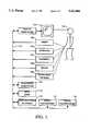
- FIG. 1is a block diagram of an apparatus in accordance with an embodiment of the invention, and which can be used to practice the method of the present invention.
- FIG. 2is a flow diagram for a generalized procedure for generating mattes, and which is used in the preferred embodiment of the present invention.
- FIG. 3is a flow diagram of the routine for inputting keyframe outlines.
- FIG. 4is a flow diagram of the routine for rendering and outputting matte elements.
- FIG. 5is a flow diagram of the routine for inputting element outlines, including the technique of the present invention.
- FIG. 6is a flow diagram of the routine for generating soft-edge mattes from their outlines.
- FIG. 7shows one embodiment of a soft-area filling technique which can be employed in the method of the present invention.
- FIG. 8shows an alternative embodiment of a soft-area filling technique which can be employed in the method of the present invention.
- FIGS. 9A, 9B, 9Care diagrams illustration examples of the use of the present invention to generate a soft-edge matte for an object and its shadow penumbra.
- FIGS. 10A-10Care diagrams illustrating examples of the use of the present invention to generate a soft-edge matte for a motion blurred object.
- FIG. 1there is shown a block diagram of an apparatus in accordance with an embodiment of the present invention, and which can be used to practice the method of the invention.
- An operator 100works with input devices 105-109 for specifying matte outlines and for controlling the process for generating soft-edge mattes, and with a display device 104 to monitor input and control of the process. These devices are coupled to processor control circuitry 101 and data base storage 102, implemented in the present embodiment by a conventional general-purpose computer such as a Silicon Graphics work station with graphics display 104, keyboard 106, and mouse 108, tablet 105, or other pointing input devices. Also in the present embodiment, input and output devices 100-112 for scanning pictures into the system data base and for outputting the mattes or foreground elements are optionally provided.
- FIG. 2there is shown a generalized flow diagram of a typical procedure for generating mattes in accordance with an embodiment of the invention.
- the processmay rely upon the operator 100 to specify 200 the source of the input images and where the matte output is to be stored.
- the block 201represents the input of the keyframe regions, typically performed by the operator through a sequence of steps using the input devices.
- alternative embodiments of the inventionmay employ alternative techniques for identifying the matte regions, such as image-processing techniques for edge detection.
- Which mattes to generate and in what framesare indicated at 202, and the renderings are stored 203 for subsequent use of the mattes thus generated. It will be understood that variations of this procedure can be employed, consistent with the principles of the invention, depending upon the number and size of the images, the specific types of input and output devices, and upon operator preferences.
- FIG. 3there is shown a flow diagram for a typical routine for inputting the keyframe outlines 201.
- the operatormay store the inputs provided and terminate the procedure for resuming at a later time.
- Decision 300determines whether this condition exists, in which case the previously-stored keyframes data are retrieved 301 from the data base.
- Decision 302determines whether further input is required from the operator. If no more input or modification of input is required, the process proceeds to block 202 of FIG. 2. Otherwise, the process proceeds to step 303 which represents the process by which the operator identifies which keyframe data is to be input or modified.
- the specified frame datais retrieved 304 from the data base, and is displayed 305.
- the operatorinputs or modifies the matte element outlines 306, as described in more detail below.
- Decision 307determines whether all required input has been supplied. If not, the process returns 303 for more input. Once all input has been supplied, the process stores 308 the keyframe matte outlines for subsequent processing.
- Matte outlines for the interpolated in-between framesare calculated 400 from the keyframe outlines according to various techniques conventionally known to skilled practitioners of the art.
- a conventional method of cubic piece-wise polynomial spline interpolationis used.
- the block 401represents the procedure for rendering the solid mattes areas which will be readily known to skilled practitioners of the art; in the present embodiment the method of approximating the solid matte area with polygons and rendering in an anti-aliased fashion is used.
- the soft matte regionsare then generated 402 in accordance with an embodiment of the invention, as described in more detail below.
- the procedureoutputs the soft-edge matte 403 by storing into the database or recording onto one of the optional output devices or by subsequent image processing.
- Decision 404determines whether all required matte frames have been generated, and if not, the process returns to step 400 and another frame is processed. If all soft-edge mattes have been generated 404, the process is complete. It will be understood, however, that variations of this typical routine can be also employed, for example, the soft-edge regions for a frame can be generated before the solid regions are rendered for a frame, or all the solid regions for every frame can be rendered and then all the soft-edge regions for every frame can be generated, as convenient.
- FIG. 5there is shown a flow diagram of the routine for inputting element outlines in step 306 of FIG. 3.
- the solid matte areas and holesare specified 500, and the soft-edge regions are specified 501 typically by the operator using an input device and a graphical display for visual registration with the subject image.
- alternate embodiments of the inventionmay use more automated methods such as conventional edge-detection image processing methods.
- the operatorconstructs the outlines by using the mouse or other input device to select certain control points around the visual display object or element, and a suitable routine well-known in the art is used to construct the outline from these control points, such as the method of cubic piece-wise polynomial splines.
- control point positionsare used to contract both the inside (solid) and outside (soft-edge) outlines for typical hard-edge elements, and the operator indicates that a soft-edge matte is required by selecting a control point for one outline and moving the outlines apart to create the soft-edge area.
- a soft-edge matteis required by selecting a control point for one outline and moving the outlines apart to create the soft-edge area.
- one set of outline control pointsmay be specified according to offsets from another set, or the number of inside and outside outline control points may differ, or an outline representation which does not use control points may be employed.
- An optional procedure 502may be used in accordance with an embodiment of the invention in which additional falloff contours may be specified to adjust the characteristics of the soft-edge region.
- Step 503represents the procedure for displaying the image together with the matte regions.
- the foreground element imageis displayed and then outlines of the solid matte regions and soft-edge regions are drawn over in registration with the image such that both are made visible according to various conventional display schemes.
- Decision 504determines whether the outlines are in the desired position, and typically this is determined by inspection by the operator using the graphics display, although alternative embodiments of the invention may employ more automated conventional image analysis methods. If the outlines are not in their desired positions, the routine proceeds to modify the outlines 505, and then back to step 503. If the outlines are in their desired positions, the routine proceeds to decision 307 of FIG. 3.
- the step 600represents the procedure by which the pixels in the soft-edge region are determined.
- Step 601represents the selection of a pixel within the soft-edge region for filling.
- the relative location of the pixelis determined 602 with respect to the solid and soft-edge boundaries, as employed in a typical embodiment of the invention and described in more detail below.
- the matte value for this pixelis computed 603, as described in more detail below for a typical embodiment of the invention.
- Decision 604determines whether any more pixels in the soft-edge region remain to be processed, and if matte values for all pixels in the soft-edge region have not been computed, then the routine flows to step 605 for selecting another pixel from the soft-edge region, and then flows back to step 602. If all soft-edge pixels have been processed the routine flows to step 403 of FIG. 4 for output, or storage subsequently used.
- FIG. 7there is shown an embodiment of a soft-area filling technique as can be employed in the procedure 402 of FIG. 4.
- a nearby point 703is chosen also on the solid matte boundary and with a distance from point 702 of approximately one pixel.
- the point 704is then computed as the midpoint of these two points, and may lie only approximately close to the solid matte boundary.
- Points 705 and 706are computed to lie along the soft-edge boundary 701 and to have the same parametric distance from a reference point on their boundary as points 702 and 703 have along their boundary, respectively.
- the point 707is then computed as the midpoint of points 705 and 706, and may lie only approximately close to the soft-edge matte boundary.
- a sequence of points along the line from 704 to 707 at a spacing of approximately one pixel in distanceare computed and are represented by the typical point 708.
- Circle 709represents the area within a small distance of point 708 contained by the lines joining points 702 and 705, and points 703 and 706, respectively. All pixels fully or partially contained by circle 709 are assigned a soft-area matte value according to a computation which may consider the distances to points 704 and 707, typically formulated to generate gradient values from opaque at point 704 to transparent at point 707.
- optional soft-edge falloff contoursas specified in Step 502 of FIG. 5, may be used in the gradient calculation.
- FIG. 8there is shown an alternative embodiment of a soft-area filling technique as can be employed in step 402 of FIG. 4.
- a nearby point 803is chosen also on the solid matte boundary and with a distance from point 802 of approximately one pixel.
- Points 804 and 805are computed to lie along the soft-edge boundary 801 and to have the same parametric distances from a reference point on their boundary as points 802 and 803 have along their boundary, respectively.
- the quadrilateral thus formed by these four pointsis then rendered as an approximation to the actual soft-edge region bounded by these points using a conventional gradient polygon fill method known in the art.
- FIGS. 9A-9Cthere are shown diagrams illustrating an example of the use of the invention to generate a soft-edge matte for an image of an object and its shadow penumbra.
- Object 900is illuminated by area light source 901.
- Light rays 902cast a shadow 903 upon a surface. Partial obscuring of the area of the light 901 by the object 900 results in soft-edge shadow penumbra 905 which eventually fades away at extremity 904.
- the method of the current inventionis employed to generate solid matte outline 906 and soft-edge matte outline 907, as shown in FIG. 9B.
- These regionsare then filled in accordance with an embodiment of the invention to produce the soft-edge matte with solid area 908 and soft area 909, as shown in FIG. 9C.
- This mattecan then be subsequently used to extract the object element and its soft-edge shadow for compositing and other effects.
- FIGS. 10A-10Cthere are shown diagrams illustrating an example of the use of the invention to generate a soft-edge matte for the display image of a motion-blurred object 1000.
- An image of a speeding bullet 1000can exhibit blurriness as a result of its movement during the image recording process.
- the method of the current inventionis employed to generate the solid matte outline 1001 and the soft-edge matte outline 1002. These regions are then filled in accordance with an embodiment of the invention to produce the soft-edge matte with solid area 1003 and soft area 1004. This matte can then be subsequently used to extract the blurred object element for compositing and other effects.
- the method of the present inventionmay also be employed in connection with image processing techniques other than mattes, in order to generate soft edges for such techniques.
- image processing techniquesother than mattes
- the method of the present inventionmay be used to achieve soft edges for the elements.
- tintingwill be applied at lesser intensity at the soft-edge boundaries in accordance with the techniques described above.
Landscapes
- Engineering & Computer Science (AREA)
- Computer Graphics (AREA)
- Physics & Mathematics (AREA)
- General Physics & Mathematics (AREA)
- Theoretical Computer Science (AREA)
- Image Analysis (AREA)
Abstract
Description
Claims (22)
Priority Applications (1)
| Application Number | Priority Date | Filing Date | Title |
|---|---|---|---|
| US08/061,492US5422986A (en) | 1993-05-12 | 1993-05-12 | Method for generating soft-edge mattes for visual elements of images |
Applications Claiming Priority (1)
| Application Number | Priority Date | Filing Date | Title |
|---|---|---|---|
| US08/061,492US5422986A (en) | 1993-05-12 | 1993-05-12 | Method for generating soft-edge mattes for visual elements of images |
Publications (1)
| Publication Number | Publication Date |
|---|---|
| US5422986Atrue US5422986A (en) | 1995-06-06 |
Family
ID=22036140
Family Applications (1)
| Application Number | Title | Priority Date | Filing Date |
|---|---|---|---|
| US08/061,492Expired - LifetimeUS5422986A (en) | 1993-05-12 | 1993-05-12 | Method for generating soft-edge mattes for visual elements of images |
Country Status (1)
| Country | Link |
|---|---|
| US (1) | US5422986A (en) |
Cited By (31)
| Publication number | Priority date | Publication date | Assignee | Title |
|---|---|---|---|---|
| US5739819A (en)* | 1996-02-05 | 1998-04-14 | Scitex Corporation Ltd. | Method and apparatus for generating an artificial shadow in a two dimensional color image |
| US5870098A (en)* | 1997-02-26 | 1999-02-09 | Evans & Sutherland Computer Corporation | Method for rendering shadows on a graphical display |
| US5894309A (en)* | 1997-02-27 | 1999-04-13 | Mitsubishi Electric Information Technology Center America, Inc. | System for modifying lighting in photographs |
| WO1999027493A3 (en)* | 1997-11-25 | 1999-09-23 | Interval Research Corp | Detection of image correspondence using radial cumulative similarity |
| US6356265B1 (en)* | 1998-11-12 | 2002-03-12 | Terarecon, Inc. | Method and apparatus for modulating lighting with gradient magnitudes of volume data in a rendering pipeline |
| US20020036638A1 (en)* | 2000-09-25 | 2002-03-28 | Konami Corporation | Three-dimensional image processing method and apparatus, readable storage medium storing three-dimensional image processing program and video game system |
| US6369816B1 (en)* | 1998-11-12 | 2002-04-09 | Terarecon, Inc. | Method for modulating volume samples using gradient magnitudes and complex functions over a range of values |
| US20020047843A1 (en)* | 2000-08-31 | 2002-04-25 | Konami Corporation | Three-dimensional image processing method and apparatus, readable storage medium storing three-dimensional image processing program and video game system |
| US6393134B1 (en)* | 1997-03-07 | 2002-05-21 | Phoenix Licensing, Inc. | Digital cartoon and animation process |
| US20020062481A1 (en)* | 2000-02-25 | 2002-05-23 | Malcolm Slaney | Method and system for selecting advertisements |
| US6411296B1 (en)* | 1998-11-12 | 2002-06-25 | Trrarecon, Inc. | Method and apparatus for applying modulated lighting to volume data in a rendering pipeline |
| US6426749B1 (en)* | 1998-11-12 | 2002-07-30 | Terarecon, Inc. | Method and apparatus for mapping reflectance while illuminating volume data in a rendering pipeline |
| US6574793B1 (en) | 2000-02-25 | 2003-06-03 | Interval Research Corporation | System and method for displaying advertisements |
| US20030206895A1 (en)* | 1998-11-13 | 2003-11-06 | Sigma-Tau Healthscience S.P.A. | Antioxidant composition comprising propionyl L-carnitine and a flavonoid against throm-bosis and atherosclerosis |
| US20030228081A1 (en)* | 2002-05-02 | 2003-12-11 | Tavlykaev Robert F. | Optical modulators with coplanar-waveguide-to-coplanar-strip electrode transitions |
| US20040239673A1 (en)* | 2003-05-30 | 2004-12-02 | Schmidt Karl Johann | Rendering soft shadows using depth maps |
| US6917371B1 (en)* | 1996-11-22 | 2005-07-12 | Kabushiki Kaisha Sega Enterprises | Game device, picture data forming method and medium |
| US7082223B1 (en)* | 2000-02-28 | 2006-07-25 | Adobe Systems Incorporated | Reducing aliasing artifacts when shaping a digital image |
| US20080109284A1 (en)* | 2000-02-25 | 2008-05-08 | Malcolm Slaney | Auction for targeted content |
| US7439975B2 (en) | 2001-09-27 | 2008-10-21 | International Business Machines Corporation | Method and system for producing dynamically determined drop shadows in a three-dimensional graphical user interface |
| US20090058880A1 (en)* | 2007-09-04 | 2009-03-05 | Apple Inc. | Anti-aliasing of a graphical object |
| US20090210902A1 (en)* | 2000-02-25 | 2009-08-20 | Malcolm Slaney | Targeted television content display |
| US20100033429A1 (en)* | 2006-09-29 | 2010-02-11 | Koninklijke Philips Electronics N.V. | 3d connected shadow mouse pointer |
| US7764286B1 (en)* | 2006-11-01 | 2010-07-27 | Adobe Systems Incorporated | Creating shadow effects in a two-dimensional imaging space |
| US7778519B2 (en) | 1999-11-18 | 2010-08-17 | Interval Licensing Llc | Iterative, maximally probable, batch-mode commercial detection for audiovisual content |
| US7891818B2 (en) | 2006-12-12 | 2011-02-22 | Evans & Sutherland Computer Corporation | System and method for aligning RGB light in a single modulator projector |
| US8077378B1 (en) | 2008-11-12 | 2011-12-13 | Evans & Sutherland Computer Corporation | Calibration system and method for light modulation device |
| US8358317B2 (en) | 2008-05-23 | 2013-01-22 | Evans & Sutherland Computer Corporation | System and method for displaying a planar image on a curved surface |
| US8702248B1 (en) | 2008-06-11 | 2014-04-22 | Evans & Sutherland Computer Corporation | Projection method for reducing interpixel gaps on a viewing surface |
| US20160042553A1 (en)* | 2014-08-07 | 2016-02-11 | Pixar | Generating a Volumetric Projection for an Object |
| US9641826B1 (en) | 2011-10-06 | 2017-05-02 | Evans & Sutherland Computer Corporation | System and method for displaying distant 3-D stereo on a dome surface |
Citations (4)
| Publication number | Priority date | Publication date | Assignee | Title |
|---|---|---|---|---|
| US5170440A (en)* | 1991-01-30 | 1992-12-08 | Nec Research Institute, Inc. | Perceptual grouping by multiple hypothesis probabilistic data association |
| US5179641A (en)* | 1989-06-23 | 1993-01-12 | Digital Equipment Corporation | Rendering shaded areas with boundary-localized pseudo-random noise |
| US5220650A (en)* | 1991-01-22 | 1993-06-15 | Hewlett-Packard Company | High speed method for rendering antialiased vectors |
| US5251160A (en)* | 1988-02-23 | 1993-10-05 | Evans & Sutherland Computer Corporation | System for blending surfaces in geometric modeling |
- 1993
- 1993-05-12USUS08/061,492patent/US5422986A/ennot_activeExpired - Lifetime
Patent Citations (4)
| Publication number | Priority date | Publication date | Assignee | Title |
|---|---|---|---|---|
| US5251160A (en)* | 1988-02-23 | 1993-10-05 | Evans & Sutherland Computer Corporation | System for blending surfaces in geometric modeling |
| US5179641A (en)* | 1989-06-23 | 1993-01-12 | Digital Equipment Corporation | Rendering shaded areas with boundary-localized pseudo-random noise |
| US5220650A (en)* | 1991-01-22 | 1993-06-15 | Hewlett-Packard Company | High speed method for rendering antialiased vectors |
| US5170440A (en)* | 1991-01-30 | 1992-12-08 | Nec Research Institute, Inc. | Perceptual grouping by multiple hypothesis probabilistic data association |
Cited By (53)
| Publication number | Priority date | Publication date | Assignee | Title |
|---|---|---|---|---|
| US5739819A (en)* | 1996-02-05 | 1998-04-14 | Scitex Corporation Ltd. | Method and apparatus for generating an artificial shadow in a two dimensional color image |
| US6917371B1 (en)* | 1996-11-22 | 2005-07-12 | Kabushiki Kaisha Sega Enterprises | Game device, picture data forming method and medium |
| US5870098A (en)* | 1997-02-26 | 1999-02-09 | Evans & Sutherland Computer Corporation | Method for rendering shadows on a graphical display |
| WO1998038591A3 (en)* | 1997-02-26 | 1999-02-18 | Evans & Sutherland Computer Co | Method for rendering shadows on a graphical display |
| GB2336984A (en)* | 1997-02-26 | 1999-11-03 | Evans & Sutherland Computer Co | Method for rendering shadows on a graphical display |
| GB2336984B (en)* | 1997-02-26 | 2001-09-05 | Evans & Sutherland Computer Co | Method for rendering shadows on a graphical display |
| US5894309A (en)* | 1997-02-27 | 1999-04-13 | Mitsubishi Electric Information Technology Center America, Inc. | System for modifying lighting in photographs |
| US6393134B1 (en)* | 1997-03-07 | 2002-05-21 | Phoenix Licensing, Inc. | Digital cartoon and animation process |
| WO1999027493A3 (en)* | 1997-11-25 | 1999-09-23 | Interval Research Corp | Detection of image correspondence using radial cumulative similarity |
| US6343150B1 (en) | 1997-11-25 | 2002-01-29 | Interval Research Corporation | Detection of image correspondence using radial cumulative similarity |
| US6369816B1 (en)* | 1998-11-12 | 2002-04-09 | Terarecon, Inc. | Method for modulating volume samples using gradient magnitudes and complex functions over a range of values |
| US6411296B1 (en)* | 1998-11-12 | 2002-06-25 | Trrarecon, Inc. | Method and apparatus for applying modulated lighting to volume data in a rendering pipeline |
| US6426749B1 (en)* | 1998-11-12 | 2002-07-30 | Terarecon, Inc. | Method and apparatus for mapping reflectance while illuminating volume data in a rendering pipeline |
| US6356265B1 (en)* | 1998-11-12 | 2002-03-12 | Terarecon, Inc. | Method and apparatus for modulating lighting with gradient magnitudes of volume data in a rendering pipeline |
| US20030206895A1 (en)* | 1998-11-13 | 2003-11-06 | Sigma-Tau Healthscience S.P.A. | Antioxidant composition comprising propionyl L-carnitine and a flavonoid against throm-bosis and atherosclerosis |
| US8724967B2 (en) | 1999-11-18 | 2014-05-13 | Interval Licensing Llc | Iterative, maximally probable, batch-mode commercial detection for audiovisual content |
| US8995820B2 (en) | 1999-11-18 | 2015-03-31 | Interval Licensing Llc | Iterative, maximally probable, batch-mode commercial detection for audiovisual content |
| US8630536B2 (en) | 1999-11-18 | 2014-01-14 | Interval Licensing Llc | Iterative, maximally probable, batch-mode commercial detection for audiovisual content |
| US20100281499A1 (en)* | 1999-11-18 | 2010-11-04 | Harville Michael L | Iterative, maximally probable, batch-mode commercial detection for audiovisual content |
| US7778519B2 (en) | 1999-11-18 | 2010-08-17 | Interval Licensing Llc | Iterative, maximally probable, batch-mode commercial detection for audiovisual content |
| US20080109284A1 (en)* | 2000-02-25 | 2008-05-08 | Malcolm Slaney | Auction for targeted content |
| US7661116B2 (en) | 2000-02-25 | 2010-02-09 | Vulcan Patents Llc | Auction for targeted content |
| US20020062481A1 (en)* | 2000-02-25 | 2002-05-23 | Malcolm Slaney | Method and system for selecting advertisements |
| US8522274B2 (en) | 2000-02-25 | 2013-08-27 | Interval Licensing Llc | System and method for selecting advertisements |
| US8910199B2 (en) | 2000-02-25 | 2014-12-09 | Interval Licensing Llc | Targeted television content display |
| US8930990B2 (en) | 2000-02-25 | 2015-01-06 | Interval Licensing Llc | System and method for selecting advertisements |
| US7134132B1 (en) | 2000-02-25 | 2006-11-07 | Interval Research Corporation | System and method for displaying advertisements |
| US6574793B1 (en) | 2000-02-25 | 2003-06-03 | Interval Research Corporation | System and method for displaying advertisements |
| US8185923B2 (en) | 2000-02-25 | 2012-05-22 | Interval Licensing Llc | System and method for selecting advertisements |
| US20090210902A1 (en)* | 2000-02-25 | 2009-08-20 | Malcolm Slaney | Targeted television content display |
| US7082223B1 (en)* | 2000-02-28 | 2006-07-25 | Adobe Systems Incorporated | Reducing aliasing artifacts when shaping a digital image |
| US20020047843A1 (en)* | 2000-08-31 | 2002-04-25 | Konami Corporation | Three-dimensional image processing method and apparatus, readable storage medium storing three-dimensional image processing program and video game system |
| EP1184811A3 (en)* | 2000-08-31 | 2002-09-18 | Konami Corporation | Three-dimensional image processing method and apparatus and video game system |
| US6888547B2 (en) | 2000-08-31 | 2005-05-03 | Konami Corporation | Three-dimensional image processing method and apparatus, readable storage medium storing three-dimensional image processing program and video game system |
| US6897865B2 (en) | 2000-09-25 | 2005-05-24 | Konami Corporation | Three-dimensional image processing method and apparatus, readable storage medium storing three-dimensional image processing program and video game system |
| EP1191482A3 (en)* | 2000-09-25 | 2002-09-11 | Konami Corporation | Three-dimensional image processing method and apparatus |
| US20020036638A1 (en)* | 2000-09-25 | 2002-03-28 | Konami Corporation | Three-dimensional image processing method and apparatus, readable storage medium storing three-dimensional image processing program and video game system |
| US7439975B2 (en) | 2001-09-27 | 2008-10-21 | International Business Machines Corporation | Method and system for producing dynamically determined drop shadows in a three-dimensional graphical user interface |
| US20030228081A1 (en)* | 2002-05-02 | 2003-12-11 | Tavlykaev Robert F. | Optical modulators with coplanar-waveguide-to-coplanar-strip electrode transitions |
| US20040239673A1 (en)* | 2003-05-30 | 2004-12-02 | Schmidt Karl Johann | Rendering soft shadows using depth maps |
| US20100033429A1 (en)* | 2006-09-29 | 2010-02-11 | Koninklijke Philips Electronics N.V. | 3d connected shadow mouse pointer |
| US8493389B2 (en)* | 2006-09-29 | 2013-07-23 | Koninklijke Philips Electronics N.V. | 3D connected shadow mouse pointer |
| US7764286B1 (en)* | 2006-11-01 | 2010-07-27 | Adobe Systems Incorporated | Creating shadow effects in a two-dimensional imaging space |
| US7891818B2 (en) | 2006-12-12 | 2011-02-22 | Evans & Sutherland Computer Corporation | System and method for aligning RGB light in a single modulator projector |
| US20090058880A1 (en)* | 2007-09-04 | 2009-03-05 | Apple Inc. | Anti-aliasing of a graphical object |
| US8294730B2 (en)* | 2007-09-04 | 2012-10-23 | Apple Inc. | Anti-aliasing of a graphical object |
| US8358317B2 (en) | 2008-05-23 | 2013-01-22 | Evans & Sutherland Computer Corporation | System and method for displaying a planar image on a curved surface |
| US8702248B1 (en) | 2008-06-11 | 2014-04-22 | Evans & Sutherland Computer Corporation | Projection method for reducing interpixel gaps on a viewing surface |
| US8077378B1 (en) | 2008-11-12 | 2011-12-13 | Evans & Sutherland Computer Corporation | Calibration system and method for light modulation device |
| US9641826B1 (en) | 2011-10-06 | 2017-05-02 | Evans & Sutherland Computer Corporation | System and method for displaying distant 3-D stereo on a dome surface |
| US10110876B1 (en) | 2011-10-06 | 2018-10-23 | Evans & Sutherland Computer Corporation | System and method for displaying images in 3-D stereo |
| US20160042553A1 (en)* | 2014-08-07 | 2016-02-11 | Pixar | Generating a Volumetric Projection for an Object |
| US10169909B2 (en)* | 2014-08-07 | 2019-01-01 | Pixar | Generating a volumetric projection for an object |
Similar Documents
| Publication | Publication Date | Title |
|---|---|---|
| US5422986A (en) | Method for generating soft-edge mattes for visual elements of images | |
| US8160390B1 (en) | Minimal artifact image sequence depth enhancement system and method | |
| US8073247B1 (en) | Minimal artifact image sequence depth enhancement system and method | |
| EP1372109B1 (en) | Method and system for enhancing portrait images | |
| US7187788B2 (en) | Method and system for enhancing portrait images that are processed in a batch mode | |
| Wallace | Merging and transformation of raster images for cartoon animation | |
| US8947422B2 (en) | Gradient modeling toolkit for sculpting stereoscopic depth models for converting 2-D images into stereoscopic 3-D images | |
| Ding et al. | Importance filtering for image retargeting | |
| US8953905B2 (en) | Rapid workflow system and method for image sequence depth enhancement | |
| US5093717A (en) | System and method for digitally coloring images | |
| JPH05205042A (en) | Method of synthesizing image | |
| Mitsunaga et al. | Autokey: Human assisted key extraction | |
| US20050226502A1 (en) | Stylization of video | |
| US5515109A (en) | Backing color and luminance nonuniformity compensation | |
| MXPA03010039A (en) | Image sequence enhancement system and method. | |
| WO2001026050A2 (en) | Improved image segmentation processing by user-guided image processing techniques | |
| CN114596213B (en) | Image processing method and device | |
| US20060055708A1 (en) | Graphical user interface for a keyer | |
| Luo et al. | Controllable motion-blur effects in still images | |
| US11308586B2 (en) | Method for applying a vignette effect to rendered images | |
| US20220215512A1 (en) | Method for Emulating Defocus of Sharp Rendered Images | |
| US20060055707A1 (en) | Graphical user interface for a keyer | |
| AU2024202871B1 (en) | Image generation | |
| KR20000048054A (en) | Method of creating animation and computer readable medium | |
| Bergman et al. | Generative Neural Articulated Radiance Fields–Supplementary Document– |
Legal Events
| Date | Code | Title | Description |
|---|---|---|---|
| AS | Assignment | Owner name:PACIFIC DATA IMAGES, INC., CALIFORNIA Free format text:ASSIGNMENT OF ASSIGNORS INTEREST;ASSIGNOR:NEELY, SHAWN R.;REEL/FRAME:006567/0912 Effective date:19930512 | |
| STPP | Information on status: patent application and granting procedure in general | Free format text:APPLICATION UNDERGOING PREEXAM PROCESSING | |
| FEPP | Fee payment procedure | Free format text:PAT HLDR NO LONGER CLAIMS SMALL ENT STAT AS SMALL BUSINESS (ORIGINAL EVENT CODE: LSM2); ENTITY STATUS OF PATENT OWNER: LARGE ENTITY | |
| FPAY | Fee payment | Year of fee payment:4 | |
| AS | Assignment | Owner name:JPMORGAN CHASE BANK, AS ADMINISTRATIVE AGENT, TEXA Free format text:SECURITY INTEREST;ASSIGNOR:PACIFIC DATA IMAGES, INC. (CA CORPORATION);REEL/FRAME:013372/0853 Effective date:20021015 | |
| FPAY | Fee payment | Year of fee payment:8 | |
| AS | Assignment | Owner name:PACIFIC DATA IMAGES LLC, CALIFORNIA Free format text:ASSIGNMENT OF ASSIGNORS INTEREST;ASSIGNOR:PACIFIC DATA IMAGES, INC.;REEL/FRAME:013776/0198 Effective date:19970420 | |
| AS | Assignment | Owner name:JPMORGAN CHASE BANK, AS ADMINISTRATIVE AGENT, TEXA Free format text:SECURITY AGREEMENT;ASSIGNOR:PACIFIC DATA IMAGES L.L.C.;REEL/FRAME:015348/0990 Effective date:20041102 | |
| FPAY | Fee payment | Year of fee payment:12 | |
| AS | Assignment | Owner name:JPMORGAN CHASE BANK, N.A., AS ADMINISTRATIVE AGENT Free format text:SECURITY AGREEMENT;ASSIGNOR:PACIFIC DATA IMAGES L.L.C.;REEL/FRAME:021450/0591 Effective date:20080711 | |
| AS | Assignment | Owner name:DREAMWORKS ANIMATION L.L.C., CALIFORNIA Free format text:TERMINATION AND RELEASE OF SECURITY INTEREST IN PATENT RIGHTS;ASSIGNOR:JPMORGAN CHASE BANK, N.A., AS ADMINISTRATIVE AGENT;REEL/FRAME:028794/0770 Effective date:20120810 Owner name:PACIFIC DATA IMAGES L.L.C., CALIFORNIA Free format text:TERMINATION AND RELEASE OF SECURITY INTEREST IN PATENT RIGHTS;ASSIGNOR:JPMORGAN CHASE BANK, N.A., AS ADMINISTRATIVE AGENT;REEL/FRAME:028794/0770 Effective date:20120810 | |
| AS | Assignment | Owner name:JPMORGAN CHASE BANK, N.A., AS ADMINISTRATIVE AGENT Free format text:SECURITY AGREEMENT;ASSIGNOR:PACIFIC DATA IMAGES L.L.C.;REEL/FRAME:028801/0958 Effective date:20120810 | |
| AS | Assignment | Owner name:PACIFIC DATA IMAGES, L.L.C., CALIFORNIA Free format text:RELEASE BY SECURED PARTY;ASSIGNOR:JPMORGAN CHASE BANK, N.A.;REEL/FRAME:040775/0345 Effective date:20160920 |