US5422770A - Shock bumper for a head/disk suspension - Google Patents
Shock bumper for a head/disk suspensionDownload PDFInfo
- Publication number
- US5422770A US5422770AUS08/169,031US16903193AUS5422770AUS 5422770 AUS5422770 AUS 5422770AUS 16903193 AUS16903193 AUS 16903193AUS 5422770 AUS5422770 AUS 5422770A
- Authority
- US
- United States
- Prior art keywords
- disk
- load arm
- shock
- shock bumper
- bumper
- Prior art date
- Legal status (The legal status is an assumption and is not a legal conclusion. Google has not performed a legal analysis and makes no representation as to the accuracy of the status listed.)
- Expired - Lifetime
Links
Images


Classifications
- G—PHYSICS
- G11—INFORMATION STORAGE
- G11B—INFORMATION STORAGE BASED ON RELATIVE MOVEMENT BETWEEN RECORD CARRIER AND TRANSDUCER
- G11B33/00—Constructional parts, details or accessories not provided for in the other groups of this subclass
- G11B33/02—Cabinets; Cases; Stands; Disposition of apparatus therein or thereon
- G11B33/08—Insulation or absorption of undesired vibrations or sounds
Definitions
- This inventionrelates to structure for absorbing forces resultant from shock and, in particular, to structure for absorbing forces from a non-operational shock inflicted upon a computer disk drive, i.e., a shock inflicted during storage or transport of the computer disk drive.
- informationis frequently stored in a magnetic film on the surface of a hard or soft disk.
- the informationis stored in concentric tracks in the magnetic film, and is written to or read from the film by means of a magnetic head (or “slider” or “transducer”).
- a magnetic heador "slider” or “transducer”
- the magnetic headrides on a thin laminar boundary layer of air over the rapidly rotating disk, thereby avoiding direct contact of the head with the magnetic surface of the disk.
- the magnetic headis mounted near the end of a member commonly referred to as an actuator.
- actuatorsTwo configurations of actuators, linear and rotary, have been widely used.
- the actuatormoves linearly along a radial line of the disk to position the magnetic head at a desired position above the magnetic surface of the disk.
- the actuatorrotates about a pivot point near the periphery of the disk, the magnetic head swinging so as to define an arc as the magnetic head is positioned above the magnetic surface of the disk.
- Disk drivesare further categorized by the position of the magnetic head when the drive is not operating.
- a dynamic loading drivethe actuator on which the magnetic head is mounted is withdrawn to a position away from the disk (typically on a ramp) when the drive is not operating.
- a contact start/stop drivethe magnetic head rests at a "park" position on a non-data region of the surface of the disk (typically the inner portion thereof) when the drive is not operating.
- Vibrations and shocks that may damage the disk drivecan occur during operation of the disk drive ("operational” vibrations and shocks). Shocks can also occur while the disk drive is not operating (“non-operational” or “non-op” shocks), such as during storage or transport of the disk drive. Damage due to shock and/or vibration has become even more of a problem with the advent of "laptop” and "hand-held” computers, which are often used in severe environments and bumped or dropped repeatedly as they are moved from place to place.
- Both dynamic loading and contact start/stop disk drivesneed to be protected against external vibration and shocks.
- the bearings of the spindle-motorare particularly vulnerable.
- a sizeable shock imposed on the drivecan plastically deform or Brinell the races in these bearings.
- Such deformations in the bearing racesmay cause the disk to wobble in a lateral direction as it rotates (a condition referred to as "high runout") and may create tracking problems.
- Acoustic degradation caused by the clicking of the Brinelled bearingsmay also result.
- Brinellingcreates undue friction in the bearings and may slow down the rotation of the disk or prevent the disk from rotating altogether.
- a shock on the drivemay lead to "head slap", in which the head is lifted from and falls back to the surface of the disk. Such contact between the head and disk can damage the head and/or the disk surface.
- a disk drive having a disk-to-disk spacing of less than 2.25 mmrequires a clearance between the disk and actuator of less than 0.22 mm in order to package four magnetic heads and two disks in a type 3 form factor disk drive.
- a smaller displacement of the diskas compared to older drives, can result in contact between the disk and other components of the disk drive.
- the smaller pre-loadse.g., 3.0 to 4.0 grams, used with 50% sliders are not adequate to hold the head gimbal assembly (i.e., magnetic head mounted on a suspension) of the actuator in the rest position for relatively large shocks, e.g., 150 g's of acceleration, so that the head gimbal assembly is lifted up and then falls, resulting in contact of the head gimbal assembly with the disk.
- the baseplate thickness in many newer driveshas been reduced.
- the disk drive spin motoris attached to the baseplate and one or more disks are attached to the spin motor.
- the thinner baseplateallows increased displacement of the high mass spin motor, resulting in increased displacement of the attached disk or disks and greater danger of contact with other disk drive components.
- the disks of the disk drivecan also deflect, resulting in contact between the disks and a disk drive component.
- disk driveshave been mounted with elastomeric grommets and screws or with isolators having studs attached to the ends. Both of these methods have disadvantages. First, grommets or isolators take up significant space, and space is at a premium in a small computer. Second, these methods involve several parts which must be assembled and installed. The extra expense arising from these steps can be substantial in the context of mounting a relatively small component such as a disk drive in a laptop, hand-held or other miniature computer.
- a disk driveincludes structure that prevents a data region of a disk surface, i.e., a region of the disk surface at which data are magnetically stored, from being damaged as a result of contact between the data region and other components of the disk drive that may otherwise result from non-operational shocks (i.e., shocks that occur when the disk drive is not in use and the magnetic head of the disk drive is in a parked position) sustained by the disk drive.
- non-operational shocksi.e., shocks that occur when the disk drive is not in use and the magnetic head of the disk drive is in a parked position
- the structure according to the inventionenables large non-operational vertical shocks (shocks that cause relative motion between a disk and other components of the disk drive in a direction perpendicular to the data region surface of the disk) to be sustained by thin disk drives with small spacing between each disk of the drive and one or more head gimbal assemblies adjacent each of the disks.
- a disk drivein one embodiment, includes a base, a disk rotatably attached to the base, and a retaining structure attached to the base.
- the retaining structureincludes portions that extend, above and below the disk, respectively, from a location beyond the periphery of the disk to a location within the periphery of the disk, but outside of the data region of the disk surface. In one particular embodiment, the portions do not extend beyond the flyable radius of the disk.
- the retaining structurelimits displacement of the disk in a direction perpendicular to the surface of the disk to prevent the data region from contacting other components of the disk drive, thereby preventing damage to the data region.
- a disk drive according to the inventioncan include more than one of the above-described retaining structures and, given sufficient room within the disk drive to accommodate the additional retaining structures, the presence of additional retaining structures is generally advantageous to provide more stable retention of the disk.
- the retaining structuresare located approximately equidistant from each other around the circumference of the disk; however, this is not necessary to the invention.
- Disk drives according to the inventioncan include more than one disk.
- the retaining structure or structuresinclude a sufficient number of extending portions to restrain movement of each of the disks during a non-operational shock.
- Surfaces of the retaining structure that can contact the diskare made of a material having a low modulus of elasticity relative to the modulus of elasticity of the disk material.
- the surfaces of the retaining structureare made of plastic.
- the surfaces of the retaining structureare made of a material selected from the group consisting of Delrin (manufactured by du Pont), polycarbonate and Ultem (manufactured by GE Plastics).
- the retaining structurecan be made entirely of the same material in one process step.
- a disk drivein another embodiment, includes a base, a disk rotatably attached to the base, a suspension for supporting a transducer and a shock bumper attached to a surface of the suspension such that the shock bumper prevents contact between a data region of a disk surface and the suspension that would otherwise result from displacement of the disk relative to the suspension in a direction perpendicular to the surface of the disk.
- the shock bumperis positioned such that the shock bumper can only contact the surface of the disk outside of the flyable radius of the disk.
- the shock bumperis positioned near the location of minimum clearance between the suspension and the disk when the transducer is in a parked position.
- Disk drives according to the inventioncan include more than one disk.
- a shock bumperis attached to each suspension at a surface that is adjacent to a disk.
- the surfaces of the shock bumper that can contact the diskare made of a material having a low modulus of elasticity relative to the modulus of elasticity of the disk material.
- the surfaces of the shock bumperare made of plastic.
- the surfaces of the shock bumperare made of polyester.
- the shock bumpercan be made entirely of the same material in one process step.
- the shock bumperis made with a shape that is symmetric with respect to a longitudinal axis of the suspension.
- the symmetric shape of the shock bumperallows a single shape of shock bumper to be attached to either the upper or the lower surface of a suspension, whichever is adjacent to the disk, thus making assembly easier.
- FIG. 1Ais a simplified plan view of a dynamic loading disk drive according to the invention.
- FIG. 1Bis a more detailed plan view of the disk drive of FIG. 1A.
- FIG. 2is an end view, taken along section 1A--1A, of the cam assemblies of the disk drive of FIG. 1A.
- FIG. 3is a cross-sectional view of a retaining structure, taken along section 1B--1B of FIG. 1B, according to an embodiment of the invention.
- FIG. 4Ais a detailed plan view of an actuator and shock bumper according to an embodiment of the invention.
- FIG. 4Bis a simplified plan view of the load arm, flexure and magnetic head of FIG. 4A, without shock bumper 124.
- FIG. 4Cis a side view, taken along section 4A--4A, of the actuator of FIG. 4B.
- FIG. 5Ais a cross-sectional view of a portion of the disk drive illustrated in FIG. 1B, taken along section line 1C--1C, with the head gimbal assemblies positioned at a centermost position with respect to the disks.
- FIG. 5Bis a detailed view of a portion of FIG. 5A.
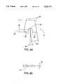
- FIGS. 6A and 6Bare a plan view and side view, respectively, Of a shock bumper according to an embodiment of the invention.
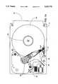
- FIG. 1Ais a simplified plan view of a dynamic loading disk drive 100 according to the invention.
- Disk drive 100includes a baseplate 101, a disk 102 and an actuator 103.
- Disk 102is driven by and rotates around a combined spindle and motor 104.
- Actuator 103rotates about a pivot shaft 108 and is driven by an actuator coil 109 (FIG. 1B) in conjunction with a magnet assembly (not shown) which together make up a voice coil motor which swivels actuator 103 so as to position a magnetic head 105 over a desired location on the surface of disk 102.
- actuator 103At one end of actuator 103 are mounted magnetic head 105 and a load rod 106 (i.e., a cam follower), the latter of which rides on a cam 107.
- load rod 106i.e., a cam follower
- actuator 103is shown positioned so that magnetic head 105 is in a flyable position, i.e., a position at which magnetic head 105 can be supported by the air bearing created by rotation of disk 102.
- FIG. 1Bis a more detailed plan view of disk drive 100.
- disk drive 100also includes retaining structures 121, 122 and 123 attached to baseplate 101, and a shock bumper 124 attached to the suspension of actuator 103. Retaining structures 121, 122 and 123, as well as shock bumper 124, are discussed in more detail below.
- actuator 103is shown positioned so that magnetic head 105 is in a parked position.
- FIG. 2is an end view, taken along section 1A--1A of FIG. 1A, of cam assemblies 257 and 267. Screws for attaching cam assemblies 257 and 267 to baseplate 101 (not shown in FIG. 2) fit into cavities 254 and 264, respectively. Projections 251a and 251b of cam assembly 257 fit into openings 253a and 253b of cam assembly 267, respectively, to interlock cam assembly 257 with cam assembly 267. Lower projections 252a and 252b of cam assembly 267 fit into corresponding openings in baseplate 101 to position cam assemblies 257 and 267 at the appropriate location with respect to load rods 106, 206, 216 and 226, and disks 102 and 202. Load rods 206, 216 and 226 are attached to actuators in a manner similar to that shown for load rod 106 and actuator 103 in FIGS. 1A and 1B.
- Cam assemblies 257 and 267operate in the same manner.
- Cam assembly 257includes cam 107 and cam assembly 267 includes cam 207.
- cam assembly 257includes cam 107 and cam assembly 267 includes cam 207.
- load rods 206, 216 and 226interact with the adjacent surface of the corresponding cam in a manner similar to that described below for load rod 106.
- Load rod 106extends beyond the end of load arm 406 (FIGS. 4A through 4C). The end of load rod 106 extending beyond load arm 406 contacts and moves along the adjacent surface of cam 107 between a park position indicated at 253 and a flying position (shown in FIG. 2) at which magnetic head 105 is allowed to fly freely above disk 102. Load rod 106 is held in contact with the surface of cam 107 by application of a force through load arm 406.
- disk drive 100can sustain non-operational shocks during, for instance, storage or transport of disk drive 100 that result in motion of disk 102, in a direction perpendicular to the surface of disk 102 shown in FIGS. 1A and 1B, relative to the other components of disk drive 100.
- Retaining structures 121, 122 and 123, and shock bumper 124prevent a data region (explained below with respect to FIG. 4A) of a surface or surfaces of disk 102 from contacting other components of disk drive 100 as a result of the non-operational shock, thereby preventing the data region from being damaged by the contact.
- a non-operational shockmay be great enough to overcome the load arm force and lift load rod 106 away from the surface of cam 107 so that when load rod 106 returns to the surface of cam 107 contact results between the data region of a surface of disk 102 and a portion of load arm 406 that overhangs disk 102 (see FIG. 4A) when magnetic head 105 is in the parked position.
- Such a shockmay also cause contact between the data region of the surface of disk 102 and a staking plate 407 (see, in particular, FIG. 4C) used to attach load arm 406 to actuator arm 405.
- a shockmay be great enough to cause deflection of disk 102 sufficient to result in the above-described contact between disk 102 and load arm 406 or staking plate 407.
- a non-operational shockmay be great enough to cause disk 102, baseplate 101 or top cover (not shown in the Figures) to deflect sufficiently to result in contact between disk 102 and baseplate 101, or between disk 102 and the top cover.
- the top coverhas a clearance of 0.3 mm from the adjacent surface of disk 102.
- FIG. 3is a cross-sectional view of retaining structure 121, taken along section 1B--1B of FIG. 1B, according to an embodiment of the invention.
- Retaining structure 122has the same shape as retaining structure 121.
- Retaining structure 123has a similar, but slightly different shape than retaining structures 121 and 122, as will be explained in more detail below.
- the disk drive spin motor(not shown in the Figures) is attached to baseplate 101 (FIGS. 1A and 1B). A hub of the spin motor extends through baseplate 101. Disk 202 is clamped to a flange of the disk drive spin motor hub.
- the spin motor and disk 202have a relatively large mass, and baseplate 101 is relatively thin (in one embodiment, approximately 0.75 mm) so that application of a shock to disk drive 100 causes baseplate 101 to deflect a relatively large amount. Additionally, disks 102 and 202 can also deflect as a result of a shock. Retaining structures 121, 122 and 123 prevent contact between one of disks 102 or 202 and one or more of baseplate 101, top cover of disk drive 100, staking plate 407 or load arm 406.
- retaining structure 121is attached to baseplate 101 with a screw 301. It is to be understood that retaining structure 121 can be attached in any other acceptable manner, such as, for instance, press-fit into a hole in baseplate 101, mechanically latched into a hole in baseplate 101, or bonded to baseplate 101 with, for example, an adhesive such as epoxy.
- Retaining structure 121includes a cylindrical body 121a and three extending portions 121b. Extending portions 121b define two cutouts 121c. Body 121a of retaining structure can have other than a cylindrical shape, e.g., a cubical shape. Additionally, retaining structure 121 can include other than three extending portions 121b. Generally, a retaining structure according to the invention includes a number of extending portions adequate to restrain each of the disks in the disk drive in which the retaining structure is included. In one embodiment, the number of extending portions of a retaining structure according to the invention is one more than the number of disks included in the disk drive.
- each of cutouts 121care made of a material having a low modulus of elasticity relative to the modulus of elasticity of the disk material, so that contact stresses between retaining structure 121 and disks 102 and 202 are minimized.
- the surfaces of cutouts 121care made of plastic.
- the surfaces of cutouts 121care made of a material selected from the group consisting of Delrin (manufactured by du Pont), polycarbonate and Ultem (manufactured by GE Plastics).
- the entire retaining structure 121can be made of the same material, i.e., the low modulus material, so that the entire retaining structure 121 can be formed at one time, thus making manufacture of retaining structure 121 easier.
- the clearance between each of extending portions 121b and the adjacent surface of disk 102 or 202must be sufficiently smaller than the minimum clearance between an actuator, e.g., actuator 103, and an adjacent disk, e.g., disk 102 so that a shock does not produce contact between the actuator, e.g., actuator 103, and the disk, e.g., disk 102.
- the clearance between each of extending portions 121b and the adjacent surface of disk 102 or 202is between 0.15 and 0.20 mm.
- Each of extending portions 121bextend within the periphery of disk 102 or 202 by an amount adequate to ensure that disk 102 or 202 is retained by extending portion 121b in the event of a large shock. At the same time, extending portions 121b do not extend beyond the beginning of the data region on disk 102 or 202 so that, in the event of contact between disk 102 or 202 and one of extending portions 121b, the data region is not damaged.
- each of the extending portionsdoes not extend beyond a flyable radius 402 (FIG. 4A) of disk 102. This is so that, if a particularly hard contact between one of extending portions 121b and one of disks 102 or 302 occurs, any deformation of disk 102 or 302 that may occur will not affect the flying characteristics of magnetic head 105 or the integrity of the data region. This is also so that contaminants that may be on extending portion 121b can only be transferred to the disk surface outside of flyable radius 402, minimizing the possibility that the contaminants will degrade the flying performance of magnetic head 105 or the integrity of the data region.
- retaining structure 123has a slightly different shape than retaining structures 121 and 122. This difference is not necessary to the invention and is merely a result of the formation of retaining structure 123 together with cam 107 for reasons explained below.
- the three extending portions of retaining structure 123extend further than the three extending portions of retaining structures 121 and 122, and, viewed from above (see FIG. 1B), form an elbow shape.
- Disk drive 100includes three retaining structures 121, 122 and 123.
- a disk drive according to the inventioncan include more or less than three retaining structures, i.e., one, two, four or more. Additional retaining structures provide more disk restraint and, if located properly, more stable disk restraint. However, additional retaining structures also increase the complexity and cost of production of the disk drive. Further, disk drive space constraints may limit the number of retaining structures.
- each of the retaining structurescan be located at any desired location. However, if possible, where more than one retaining structure is used, the retaining structures are located approximately equidistant from each other about the periphery of the disk.
- retaining structure 123is advantageously formed integrally with cam 107 so that retaining structure 123 and cam 107 can be molded as a single part at one time.
- Retaining structure 122is located in an open area near pivot shaft 108.
- Retaining structures 122 and 123are located approximately symmetrically with respect to the portion of actuator 103 that extends over the data region (discussed in more detail below with respect to shock bumper 124 and FIG. 4A) of disk 102.
- Retaining structure 121is located such that retaining structure 121 is approximately equidistant from each of retaining structures 122 and 123.
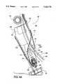
- FIG. 4Ais a detailed plan view of actuator 103 and shock bumper 124 according to an embodiment of the invention.
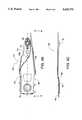
- FIG. 4Bis a simplified plan view of load arm 406, flexure 408 and magnetic head 105 without shock bumper 124.
- FIG. 4Cis a side view, taken along section 4A--4A, of actuator 103.
- shock bumper 124prevents damaging contact between disk 102 and actuator 103 that may otherwise result from relative movement of disk 102 and actuator 103 as a result of a shock imparted to disk drive 100.
- Actuator 103includes an actuator arm 405 and a load arm 406.
- a staking holeis formed in each of load arm 406 and actuator arm 405.
- load arm 406is attached to actuator arm 405 by sandwiching load arm 406 between actuator arm 405 and staking plate 407 and swaging together ("staking") load arm 406, actuator arm 405 and staking plate 407. Only a small ring of staking plate 407 extending through the staking hole of actuator arm 405 is visible in FIG. 4A.
- Load arm 406is formed integrally with a flexure 408 which is located at the end of load arm 406. Flexure 408 is formed by removing material from load arm 406 to leave a flexible portion of material that is flexure 408. In the embodiment of FIGS. 4A through 4C, a region 410 is etched from the underside of load arm 406 to achieve desired spring characteristics of load arm 406. Together, load arm 406 and flexure 408 constitute a suspension which, in this embodiment, is denoted a type 16 suspension.
- Magnetic head 105is attached to flexure 408 in a conventional manner. Together, magnetic head 105, load arm 406 and flexure 408 constitute a head gimbal assembly. Cable 411 electrically connects magnetic head 105 to the remainder of the electronics in disk drive 100.
- Load rod 106is attached to load arm 406.
- actuator 103is shown in the parked or non-operational position. In this position, actuator 103 extends beyond an edge 403 of disk 102 so that actuator 103 overlies a portion of disk 102.
- the flyable radiusi.e., the radius beyond which magnetic head 105 is not allowed to fly, is shown by arc 402. Beyond flyable radius 402, magnetic head 105 is supported by contact between load rod 106 and cam 107.
- Arc 401marks the outermost point at which data is stored on disk 102, i.e., arc 401 defines the data region on the surface of disk 102 visible in FIG. 4A.
- Load arm 406is formed with a cutout 406a.
- a cutout such as cutout 406ais necessary to provide clearance between the spin motor and the load arm of a head gimbal assembly 523 (FIGS. 5A and 5B) between baseplate 101 and disk 202.
- cutout 406ais not necessary for the load arms of other head gimbal assemblies 501, 503 and 513 of disk drive 100, each load arm is formed with such a cutout so that, during assembly, any load arm can be assembled as part of any one of head gimbal assemblies 501, 503, 513 or 523, thus making assembly of disk drive 100 easier.
- a portion of load arm 406 between cutout 406a and the staking hole of load arm 406extends over the data region, making that portion of the data region susceptible to damage from contact with load arm 406 as a result of a shock imparted to disk drive 100.
- the minimum clearance between actuator 103 and disk 102is at the cutout 406a of load arm 406, making the area of actuator 103 near cutout 406a particularly susceptible to contact with disk 102. Consequently, shock bumper 124 is located near cutout 406a so that shock bumper 124 can prevent such contact. Additionally, shock bumper 124 is located near cutout 406a so that shock bumper 124 will contact disk 102 sooner during a shock than would otherwise be the case if shock bumper 124 were located where the clearance between actuator 103 and disk 102 is greater, making shock bumper 124 more effective in preventing contact between any portion of actuator 103 and disk 102. Shock bumper 124 prevents contact between disk 102 and actuator 103 regardless of whether disk 102 or the suspension (load arm 406 and flexure 408) deflect.
- Shock bumper 124is attached to the underside of load arm 406 so that an edge 124a is just outside flyable radius 402 of disk 102. Edge 124a roughly conforms to the contour of flyable radius 402. This is so that contact between shock bumper 124 and disk 102 will be located on disk 102 outside flyable radius 402 so that neither contaminants transferred from shock bumper 124 to disk 102, nor a particularly hard contact between shock bumper 124 and disk 102 will adversely affect the flying characteristics of magnetic head 105 or the integrity of the data region within arc 401.
- Shock bumper 124is also formed with a cutout 124b so that shock bumper 124 does not overlap a tooling hole 412 which is formed in load arm 406. Likewise, shock bumper 124 does not extend beyond tooling hole 413 formed in load arm 406. This is so that tooling holes 412 and 413 are available for use during head stack assembly after shock bumper 124 has been attached to load arm 406.
- Edge 124c of shock bumper 124is preferably made as close to cutout 124b as possible, making shock bumper 124 smaller so that the mass of shock bumper 124 is minimized.
- the size of shock bumper 124is limited by the process for making shock bumper 124.
- shock bumper 124is punched from a thin sheet of material using a die. As shock bumper 124 gets increasingly smaller, at some point, the smaller die becomes too fragile for the punching process.
- Shock bumper 124is preferably made symmetric with respect to a longitudinal axis 404 (FIG. 4B) of load arm 406. This makes assembly of shock bumper 124 onto load arm 406 easier since shock bumper 124 can be attached to an upper or a lower surface of load arm 406, whichever is adjacent to disk 102. However, shock bumper 124 need not necessarily be made symmetric.
- FIG. 5Ais a cross-sectional view of a portion of disk drive 100 taken along section line 1C--1C in FIG. 1B.
- head gimbal assemblies 501, 503, 513 and 523are positioned at a centermost position with respect to disks 102 and 302, rather than near an outer edge of disks 102 and 302.
- FIG. 5Bis a detailed view of a portion of FIG. 5A.
- Head gimbal assemblies 501 and 503(FIG. 5B) are mounted on opposite sides of disk 102, and head gimbal assemblies 513 and 523 are mounted on opposite sides of disk 202.
- shock bumper and magnetic headare attached to a side of each of the load beams of the head gimbal assemblies adjacent to the corresponding disk, i.e., shock bumper 124 and magnetic head 105 are attached to load arm 406 (FIG. 4A) of head gimbal assembly 501 above disk 102, a shock bumper 504 and a magnetic head 505 are attached to the load arm of head gimbal assembly 503 below disk 102, a shock bumper 514 and a magnetic head 515 are attached to the load arm of head gimbal assembly 513 above disk 202, and a shock bumper 524 and a magnetic head 525 are attached to the load arm of head gimbal assembly 523 below disk 202.
- each shock bumpere.g., shock bumper 124
- each shock bumperis made of a thickness sufficient to guarantee that the corresponding suspension does not contact the adjacent disk surface as a result of a shock below a specified magnitude (the "shock specification").
- each of the contact surfacesis made of a material having a low modulus of elasticity relative to the modulus of elasticity of the disk material so that, during contact, shock bumpers 124, 504, 514 or 524 will conform somewhat to the surface of adjacent disk 102 or 202.
- each of the contact surfacesare made of plastic.
- each of the contact surfacesare made of polyester.
- a shock bumper according to the inventionis made entirely of the same material so that the shock bumper can be formed in one process step, and so that either surface of the shock bumper can be attached to the load arm, as described above.
- a shock bumper according to the inventionneed not necessarily be made entirely of one material; in that case, making the shock bumper symmetrical, as described above, becomes less advantageous.
- shock bumper 124is attached to load arm 406 in any suitable manner.
- shock bumper 124is attached with an acrylic adhesive.
- Acrylic adhesiveis desirable because of its low outgassing properties.
- any adhesive with low outgassing propertiescan be used.
- an adhesiveis used that meets the outgassing specification of ASTM E-595-84, E-595-77, 2.0% maximum TML, 0.50% maximum CVCM.
- shock bumper 124can be attached to load arm 406 by other methods.
- shock bumper 124could be formed with a protrusion that is press-fit into a corresponding cavity formed in load arm 406 or press-fit into one of tooling holes 412 or 413.
- shock bumper 124can be formed by die cutting shock bumper 124 from a thin sheet of material. Shock bumper 124 can also be formed by molding.
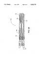
- FIGS. 6A and 6Bare a plan view and side view, respectively, of shock bumper 124.
- dimension 601is 2.45 mm
- dimension 602is 0.55 mm
- radius 603is 0.50 mm
- radii 604are each 0.25 mm
- dimension 605is 1.51 mm
- angle 606is 9.0°.
- thickness 607 of shock bumper 124is 0.250 mm with a tolerance of 0.025 mm.
Landscapes
- Supporting Of Heads In Record-Carrier Devices (AREA)
- Moving Of Heads (AREA)
Abstract
Description
Claims (12)
Priority Applications (2)
| Application Number | Priority Date | Filing Date | Title |
|---|---|---|---|
| US08/169,031US5422770A (en) | 1993-12-15 | 1993-12-15 | Shock bumper for a head/disk suspension |
| US08/250,087US5453889A (en) | 1993-12-15 | 1994-05-27 | Disk drive with disk restraint for protection against non-operational shocks |
Applications Claiming Priority (1)
| Application Number | Priority Date | Filing Date | Title |
|---|---|---|---|
| US08/169,031US5422770A (en) | 1993-12-15 | 1993-12-15 | Shock bumper for a head/disk suspension |
Related Child Applications (1)
| Application Number | Title | Priority Date | Filing Date |
|---|---|---|---|
| US08/250,087DivisionUS5453889A (en) | 1993-12-15 | 1994-05-27 | Disk drive with disk restraint for protection against non-operational shocks |
Publications (1)
| Publication Number | Publication Date |
|---|---|
| US5422770Atrue US5422770A (en) | 1995-06-06 |
Family
ID=22613998
Family Applications (2)
| Application Number | Title | Priority Date | Filing Date |
|---|---|---|---|
| US08/169,031Expired - LifetimeUS5422770A (en) | 1993-12-15 | 1993-12-15 | Shock bumper for a head/disk suspension |
| US08/250,087Expired - LifetimeUS5453889A (en) | 1993-12-15 | 1994-05-27 | Disk drive with disk restraint for protection against non-operational shocks |
Family Applications After (1)
| Application Number | Title | Priority Date | Filing Date |
|---|---|---|---|
| US08/250,087Expired - LifetimeUS5453889A (en) | 1993-12-15 | 1994-05-27 | Disk drive with disk restraint for protection against non-operational shocks |
Country Status (1)
| Country | Link |
|---|---|
| US (2) | US5422770A (en) |
Cited By (36)
| Publication number | Priority date | Publication date | Assignee | Title |
|---|---|---|---|---|
| WO1996012280A1 (en)* | 1994-10-17 | 1996-04-25 | International Business Machines Corporation | Motion limiters in a direct access storage device for preventing disk data zone and spindle bearing damage |
| US5604649A (en)* | 1993-12-23 | 1997-02-18 | International Business Machines | Disk drive system having a novel head gimbal assembly with a single offset mounting plate on each actuator arm |
| US5754371A (en)* | 1996-01-10 | 1998-05-19 | Seagate Technology, Inc. | Swage plate bumper for disc drive |
| US5801899A (en)* | 1995-10-06 | 1998-09-01 | Seagate Technology, Inc. | Mechanical shock protection for a disc drive |
| US5831793A (en)* | 1996-07-10 | 1998-11-03 | Seagate Technology, Inc. | Suspension assembly shock absorber |
| US5864444A (en)* | 1996-09-30 | 1999-01-26 | Seagate Technology, Inc. | Actuator arm bumper in a disc drive |
| WO1999009545A1 (en)* | 1997-08-15 | 1999-02-25 | Seagate Technology, Inc. | Ramp load assembly for a disc drive |
| US5903409A (en)* | 1997-01-17 | 1999-05-11 | International Business Machines Corporation | Method and means for maintaining data integrity in disk drives resulting from shock-induced contact between recording and access components during nonoperational periods |
| US6055134A (en)* | 1997-09-22 | 2000-04-25 | Seagate Technology, Inc. | Combined load/unload ramp and snubber for disc drives |
| US6057988A (en)* | 1997-07-02 | 2000-05-02 | International Business Machines Corporation | Adjustable head suspension load/unload lift cam assembly |
| US6091576A (en)* | 1998-01-21 | 2000-07-18 | Seagate Technology, Inc. | Ramp loading apparatus for a disc drive |
| US6115214A (en)* | 1997-08-15 | 2000-09-05 | Seagate Technology, Inc. | Rotary snubber assembly for a disc drive |
| US6172855B1 (en) | 1997-09-03 | 2001-01-09 | Samsung Electronics Co., Ltd. | Actuator latching device in hard disk drive |
| US6201665B1 (en)* | 1997-05-30 | 2001-03-13 | Iomega Corporation | Disk drive load ramp for protecting the actuator heads |
| US6201664B1 (en) | 1998-11-16 | 2001-03-13 | International Business Machines Corporation | Polymer bumps for trace and shock protection |
| US6212029B1 (en) | 1998-02-24 | 2001-04-03 | Seagate Technology Llc | Snubber for a disc drive |
| US6226144B1 (en)* | 1997-08-15 | 2001-05-01 | Seagate Technology Llc | Energy absorbing disc travel limiter |
| US6226145B1 (en) | 1995-10-06 | 2001-05-01 | Seagate Technology Llc | Actuator assembly mounted disc snubber |
| US6226146B1 (en) | 1998-01-08 | 2001-05-01 | Seagate Technology Llc | Multi-point interference disc spacer for a disc drive |
| US6236532B1 (en)* | 1994-08-16 | 2001-05-22 | Nec Corporation | Magnetic disk drive having small clearance between magnetic disk and surface opposing thereto |
| US6236531B1 (en) | 1995-10-06 | 2001-05-22 | Seagate Technology Llc | Flex support snubber |
| US6271996B1 (en)* | 1997-11-10 | 2001-08-07 | Hutchinson Technology Incorporated | Damper with unconstrained surface for a disk drive head suspension |
| US6271987B1 (en) | 1997-08-28 | 2001-08-07 | Seagate Technology Llc | Circumferentially extending disc snubber |
| US6351350B1 (en)* | 1999-12-09 | 2002-02-26 | Hutchinson Technology Incorporated | Shock limiter system for a head suspension |
| US6362936B2 (en)* | 1996-09-26 | 2002-03-26 | International Business Machines Corporation | Suspension assembly with integral projections having a coating of elastic material |
| US6424502B1 (en)* | 2000-04-18 | 2002-07-23 | Iomega Corporation | Roll-stabilized head lifting apparatus and method for a data storage device |
| US6477000B1 (en) | 1997-08-07 | 2002-11-05 | Seagate Technology Llc | Actuator arm disc snubber with unitary construction |
| GB2359413B (en)* | 1998-11-18 | 2002-12-24 | Seagate Technology Llc | Disc drive anti-shock suspension cushions |
| US6504683B1 (en)* | 1999-11-01 | 2003-01-07 | Hitachi, Ltd. | Magnetic disk apparatus in which contact between a disk and a carriage arm by an external impact is prevented |
| US6504684B1 (en) | 1999-12-27 | 2003-01-07 | Hutchinson Technology Incorporated | Head suspension with integral shock limiter |
| US6538850B1 (en) | 1999-10-06 | 2003-03-25 | Read-Rite Corporation | Low profile head gimbal assembly with shock limiting and load/unload capability and method of manufacture thereof |
| US6657858B2 (en)* | 1997-10-25 | 2003-12-02 | Philon Rothschild | Housing for data storage devices or for accommodating such devices |
| US6714386B1 (en) | 1998-12-07 | 2004-03-30 | Seagate Technology Llc | Disc drive having a suspension limiter for improved shock performance |
| US6731469B2 (en) | 2000-07-10 | 2004-05-04 | Seagate Technology Llc | Integral inertial latch design |
| US7085104B1 (en) | 1999-10-06 | 2006-08-01 | Western Digital (Fremont), Inc. | Low profile head gimbal assembly with shock limiting and load/unload capability |
| US20080019037A1 (en)* | 2006-07-24 | 2008-01-24 | Samsung Electronics Co., Ltd. | Disk spacer and hard disk drive having the same |
Families Citing this family (12)
| Publication number | Priority date | Publication date | Assignee | Title |
|---|---|---|---|---|
| US5790348A (en)* | 1997-07-22 | 1998-08-04 | Western Digital Corporation | Head stack assembly having a coil portion for damping vibrations which includes elongated openings in the plastic portion |
| US6583963B2 (en)* | 1997-10-07 | 2003-06-24 | Seagate Technology Llc | Apparatus to improve shock capability of disc drives |
| US6473270B1 (en)* | 1999-08-25 | 2002-10-29 | Seagate Technologies Llc | Actuator shock snubber |
| JP2002279744A (en) | 2001-03-19 | 2002-09-27 | Toshiba Corp | Magnetic disk drive |
| US7307811B2 (en)* | 2005-02-04 | 2007-12-11 | Seagate Technology Llc | Disc storage system deck with integrally formed snubbers |
| JP2008165891A (en)* | 2006-12-27 | 2008-07-17 | Toshiba Corp | Optical disk device |
| US8743509B1 (en) | 2010-05-10 | 2014-06-03 | Western Digital Technologies, Inc. | Disk drive having a head loading ramp and a disk limiter tab that projects from a side of an actuator arm |
| US8289646B1 (en) | 2010-06-24 | 2012-10-16 | Western Digital Technologies, Inc. | Disk drive having a disk limiter that is disposed within an angular range relative to a base depression brim |
| US8446688B1 (en) | 2010-06-29 | 2013-05-21 | Western Digital Technologies, Inc. | Drive with circumferential disk limiter |
| US8339732B2 (en) | 2010-09-13 | 2012-12-25 | HGST Netherlands B.V. | Baseplate with recessed region in a hard-disk drive (HDD) |
| US8553356B1 (en) | 2011-11-21 | 2013-10-08 | Western Digital Technologies, Inc. | Disk limiter for disk drive |
| US8797677B2 (en) | 2011-12-15 | 2014-08-05 | Western Digital Technologies, Inc. | Disk deflection damper for disk drive |
Citations (1)
| Publication number | Priority date | Publication date | Assignee | Title |
|---|---|---|---|---|
| US5231549A (en)* | 1988-03-01 | 1993-07-27 | Conner Peripherals, Inc. | Disk drive apparatus with cam and follower for unloading heads |
Family Cites Families (2)
| Publication number | Priority date | Publication date | Assignee | Title |
|---|---|---|---|---|
| US4863031A (en)* | 1985-12-18 | 1989-09-05 | Tdk Corporation | Disc cartridge having peripheral disc support |
| US5212679A (en)* | 1989-05-24 | 1993-05-18 | Fujitsu Limited | Disk drive for information storage |
- 1993
- 1993-12-15USUS08/169,031patent/US5422770A/ennot_activeExpired - Lifetime
- 1994
- 1994-05-27USUS08/250,087patent/US5453889A/ennot_activeExpired - Lifetime
Patent Citations (1)
| Publication number | Priority date | Publication date | Assignee | Title |
|---|---|---|---|---|
| US5231549A (en)* | 1988-03-01 | 1993-07-27 | Conner Peripherals, Inc. | Disk drive apparatus with cam and follower for unloading heads |
Cited By (49)
| Publication number | Priority date | Publication date | Assignee | Title |
|---|---|---|---|---|
| US5949615A (en)* | 1993-12-23 | 1999-09-07 | International Business Machines Corporation | Disk drive system having a novel head actuator assembly and mounting plate configuration |
| US5604649A (en)* | 1993-12-23 | 1997-02-18 | International Business Machines | Disk drive system having a novel head gimbal assembly with a single offset mounting plate on each actuator arm |
| US6236532B1 (en)* | 1994-08-16 | 2001-05-22 | Nec Corporation | Magnetic disk drive having small clearance between magnetic disk and surface opposing thereto |
| US5757587A (en)* | 1994-10-17 | 1998-05-26 | International Business Machines Corporation | Direct access storage device having a disk motion limiter for preventing disk data zone and spindle bearing damage |
| WO1996012280A1 (en)* | 1994-10-17 | 1996-04-25 | International Business Machines Corporation | Motion limiters in a direct access storage device for preventing disk data zone and spindle bearing damage |
| US5801899A (en)* | 1995-10-06 | 1998-09-01 | Seagate Technology, Inc. | Mechanical shock protection for a disc drive |
| US6236531B1 (en) | 1995-10-06 | 2001-05-22 | Seagate Technology Llc | Flex support snubber |
| US6172843B1 (en) | 1995-10-06 | 2001-01-09 | Seagate Technology Llc | Shroud mounted disc snubber |
| US6021019A (en)* | 1995-10-06 | 2000-02-01 | Seagate Technology, Inc. | Flex circuit disc snubber |
| US6226145B1 (en) | 1995-10-06 | 2001-05-01 | Seagate Technology Llc | Actuator assembly mounted disc snubber |
| US6535350B1 (en)* | 1995-10-06 | 2003-03-18 | Seagate Technology Llc | Over molded disc snubber |
| US5754371A (en)* | 1996-01-10 | 1998-05-19 | Seagate Technology, Inc. | Swage plate bumper for disc drive |
| US5831793A (en)* | 1996-07-10 | 1998-11-03 | Seagate Technology, Inc. | Suspension assembly shock absorber |
| US6362936B2 (en)* | 1996-09-26 | 2002-03-26 | International Business Machines Corporation | Suspension assembly with integral projections having a coating of elastic material |
| US5864444A (en)* | 1996-09-30 | 1999-01-26 | Seagate Technology, Inc. | Actuator arm bumper in a disc drive |
| US5903409A (en)* | 1997-01-17 | 1999-05-11 | International Business Machines Corporation | Method and means for maintaining data integrity in disk drives resulting from shock-induced contact between recording and access components during nonoperational periods |
| US6201665B1 (en)* | 1997-05-30 | 2001-03-13 | Iomega Corporation | Disk drive load ramp for protecting the actuator heads |
| US6141858A (en)* | 1997-07-02 | 2000-11-07 | International Business Machines Corporation | Head suspension lift cam adjustment |
| US6057988A (en)* | 1997-07-02 | 2000-05-02 | International Business Machines Corporation | Adjustable head suspension load/unload lift cam assembly |
| US6321442B1 (en) | 1997-07-02 | 2001-11-27 | International Business Machines Corporation | Head suspension lift cam adjustment apparatus |
| US6477000B1 (en) | 1997-08-07 | 2002-11-05 | Seagate Technology Llc | Actuator arm disc snubber with unitary construction |
| US6226144B1 (en)* | 1997-08-15 | 2001-05-01 | Seagate Technology Llc | Energy absorbing disc travel limiter |
| US6424487B2 (en) | 1997-08-15 | 2002-07-23 | Seagate Technology Llc | Energy absorbing disc travel limiter with multiple adjacent cantilevered arms to limit disc deflection |
| US6115214A (en)* | 1997-08-15 | 2000-09-05 | Seagate Technology, Inc. | Rotary snubber assembly for a disc drive |
| GB2342767A (en)* | 1997-08-15 | 2000-04-19 | Seagate Technology | Ramp load assembly for a disc drive |
| WO1999009545A1 (en)* | 1997-08-15 | 1999-02-25 | Seagate Technology, Inc. | Ramp load assembly for a disc drive |
| GB2342767B (en)* | 1997-08-15 | 2001-12-12 | Seagate Technology | Ramp load assembly for a disc drive |
| US6271987B1 (en) | 1997-08-28 | 2001-08-07 | Seagate Technology Llc | Circumferentially extending disc snubber |
| US6172855B1 (en) | 1997-09-03 | 2001-01-09 | Samsung Electronics Co., Ltd. | Actuator latching device in hard disk drive |
| US6055134A (en)* | 1997-09-22 | 2000-04-25 | Seagate Technology, Inc. | Combined load/unload ramp and snubber for disc drives |
| US6657858B2 (en)* | 1997-10-25 | 2003-12-02 | Philon Rothschild | Housing for data storage devices or for accommodating such devices |
| US6271996B1 (en)* | 1997-11-10 | 2001-08-07 | Hutchinson Technology Incorporated | Damper with unconstrained surface for a disk drive head suspension |
| US6226146B1 (en) | 1998-01-08 | 2001-05-01 | Seagate Technology Llc | Multi-point interference disc spacer for a disc drive |
| US6091576A (en)* | 1998-01-21 | 2000-07-18 | Seagate Technology, Inc. | Ramp loading apparatus for a disc drive |
| US6212029B1 (en) | 1998-02-24 | 2001-04-03 | Seagate Technology Llc | Snubber for a disc drive |
| US6201664B1 (en) | 1998-11-16 | 2001-03-13 | International Business Machines Corporation | Polymer bumps for trace and shock protection |
| GB2359413B (en)* | 1998-11-18 | 2002-12-24 | Seagate Technology Llc | Disc drive anti-shock suspension cushions |
| US6556383B2 (en) | 1998-11-18 | 2003-04-29 | Seagate Technology Llc | Disc drive anti-shock suspension cushions |
| US6714386B1 (en) | 1998-12-07 | 2004-03-30 | Seagate Technology Llc | Disc drive having a suspension limiter for improved shock performance |
| US7010847B1 (en) | 1999-10-06 | 2006-03-14 | Western Digital (Fremont), Inc. | Method of manufacturing a head gimbal assembly with substantially orthogonal tab, side beam and base |
| US6538850B1 (en) | 1999-10-06 | 2003-03-25 | Read-Rite Corporation | Low profile head gimbal assembly with shock limiting and load/unload capability and method of manufacture thereof |
| US7085104B1 (en) | 1999-10-06 | 2006-08-01 | Western Digital (Fremont), Inc. | Low profile head gimbal assembly with shock limiting and load/unload capability |
| US6504683B1 (en)* | 1999-11-01 | 2003-01-07 | Hitachi, Ltd. | Magnetic disk apparatus in which contact between a disk and a carriage arm by an external impact is prevented |
| US6351350B1 (en)* | 1999-12-09 | 2002-02-26 | Hutchinson Technology Incorporated | Shock limiter system for a head suspension |
| US6504684B1 (en) | 1999-12-27 | 2003-01-07 | Hutchinson Technology Incorporated | Head suspension with integral shock limiter |
| US6424502B1 (en)* | 2000-04-18 | 2002-07-23 | Iomega Corporation | Roll-stabilized head lifting apparatus and method for a data storage device |
| US6731469B2 (en) | 2000-07-10 | 2004-05-04 | Seagate Technology Llc | Integral inertial latch design |
| US20080019037A1 (en)* | 2006-07-24 | 2008-01-24 | Samsung Electronics Co., Ltd. | Disk spacer and hard disk drive having the same |
| US7826173B2 (en)* | 2006-07-24 | 2010-11-02 | Samsung Electronics Co. Ltd | Disk spacer and hard disk drive having the same |
Also Published As
| Publication number | Publication date |
|---|---|
| US5453889A (en) | 1995-09-26 |
Similar Documents
| Publication | Publication Date | Title |
|---|---|---|
| US5422770A (en) | Shock bumper for a head/disk suspension | |
| US6452753B1 (en) | Universal load/unload ramp | |
| US8411389B1 (en) | Disk drive fluid dynamic bearing spindle | |
| US5801899A (en) | Mechanical shock protection for a disc drive | |
| US6473270B1 (en) | Actuator shock snubber | |
| US8446688B1 (en) | Drive with circumferential disk limiter | |
| US6430007B1 (en) | Air-activated spindle/disk pack locking system | |
| US5590004A (en) | Resilient clamp and compliant element data disk support system | |
| US6583963B2 (en) | Apparatus to improve shock capability of disc drives | |
| US6226145B1 (en) | Actuator assembly mounted disc snubber | |
| EP0929069A1 (en) | Suspension assembly | |
| CN1143242A (en) | movement limiter in DASD for preventing magnetic disc data zone and main shaft bearing damage | |
| US5486961A (en) | Resilient compliant clamp for data storage disk drives | |
| US6125017A (en) | Actuator crash stops providing a two-stage braking impulse | |
| US5715119A (en) | Rotating crash stop assembly for hard disk drives | |
| US5012371A (en) | Disk drive crash stop/actuator latch | |
| US6646826B1 (en) | Integrated cover and gasket assembly | |
| KR19990044155A (en) | Crash Stop Airlock Mechanism | |
| US6201666B1 (en) | Disc drive head suspension with single-point contact feature for ramp load/unload | |
| WO1997050080A9 (en) | Crash stop airlock mechanism | |
| US7733610B2 (en) | Load/unload ramp for an actuator assembly in a data storage device | |
| US20030206368A1 (en) | Hard disk drive having disk protector and magnetic head protector | |
| US6477000B1 (en) | Actuator arm disc snubber with unitary construction | |
| US6510021B1 (en) | Mechanical isolation for a disc drive spindle motor | |
| US6744606B2 (en) | Dual plane actuator |
Legal Events
| Date | Code | Title | Description |
|---|---|---|---|
| AS | Assignment | Owner name:INTEGRAL PERIPHERALS, INC., COLORADO Free format text:ASSIGNMENT OF ASSIGNORS INTEREST;ASSIGNOR:ALT, ROBERT A.;REEL/FRAME:006858/0584 Effective date:19940208 | |
| AS | Assignment | Owner name:ASEAN STRATEGIC CAPITAL LIMITED, COLORADO Free format text:SECURITY INTEREST;ASSIGNOR:INTEGRAL PERIPHERALS, INC.;REEL/FRAME:007160/0403 Effective date:19940902 Owner name:MDM. CHING SHAI TIAN @ CHENG ENG JEE, CALIFORNIA Free format text:SECURITY INTEREST;ASSIGNOR:INTEGRAL PERIPHERALS, INC.;REEL/FRAME:007160/0403 Effective date:19940902 Owner name:ROC VENTURE COMPANY LTD., COLORADO Free format text:SECURITY INTEREST;ASSIGNOR:INTEGRAL PERIPHERALS, INC.;REEL/FRAME:007160/0403 Effective date:19940902 Owner name:YEE, VIRGINIA S., COLORADO Free format text:SECURITY INTEREST;ASSIGNOR:INTEGRAL PERIPHERALS, INC.;REEL/FRAME:007160/0403 Effective date:19940902 Owner name:SINO SCAN VENTURE FUND LTD., CALIFORNIA Free format text:SECURITY INTEREST;ASSIGNOR:INTEGRAL PERIPHERALS, INC.;REEL/FRAME:007160/0403 Effective date:19940902 Owner name:MDM. CHING LUAN JEE, CALIFORNIA Free format text:SECURITY INTEREST;ASSIGNOR:INTEGRAL PERIPHERALS, INC.;REEL/FRAME:007160/0403 Effective date:19940902 Owner name:BURLEIGH, DARRYLL, COLORADO Free format text:SECURITY INTEREST;ASSIGNOR:INTEGRAL PERIPHERALS, INC.;REEL/FRAME:007160/0403 Effective date:19940902 Owner name:GEK, CHENG THENG, CALIFORNIA Free format text:SECURITY INTEREST;ASSIGNOR:INTEGRAL PERIPHERALS, INC.;REEL/FRAME:007160/0403 Effective date:19940902 Owner name:GRAND PACIFIC LIMITED, COLORADO Free format text:SECURITY INTEREST;ASSIGNOR:INTEGRAL PERIPHERALS, INC.;REEL/FRAME:007160/0403 Effective date:19940902 Owner name:CLARIDEN BANK, COLORADO Free format text:SECURITY INTEREST;ASSIGNOR:INTEGRAL PERIPHERALS, INC.;REEL/FRAME:007160/0403 Effective date:19940902 Owner name:GAMBRILL, BRIAN H., SINGAPORE Free format text:SECURITY INTEREST;ASSIGNOR:INTEGRAL PERIPHERALS, INC.;REEL/FRAME:007160/0403 Effective date:19940902 Owner name:RAJ, NAWANEETHA, COLORADO Free format text:SECURITY INTEREST;ASSIGNOR:INTEGRAL PERIPHERALS, INC.;REEL/FRAME:007160/0403 Effective date:19940902 Owner name:HOW, CHENG THENG, CALIFORNIA Free format text:SECURITY INTEREST;ASSIGNOR:INTEGRAL PERIPHERALS, INC.;REEL/FRAME:007160/0403 Effective date:19940902 Owner name:DAVIES, STEVE, COLORADO Free format text:SECURITY INTEREST;ASSIGNOR:INTEGRAL PERIPHERALS, INC.;REEL/FRAME:007160/0403 Effective date:19940902 Owner name:MENG, TAN KIAN, COLORADO Free format text:SECURITY INTEREST;ASSIGNOR:INTEGRAL PERIPHERALS, INC.;REEL/FRAME:007160/0403 Effective date:19940902 Owner name:ROC STRATEGIC VENTURE FUND LTD., CALIFORNIA Free format text:SECURITY INTEREST;ASSIGNOR:INTEGRAL PERIPHERALS, INC.;REEL/FRAME:007160/0403 Effective date:19940902 Owner name:ASIA PACIFIC GROWTH FUND, L.P., CALIFORNIA Free format text:SECURITY INTEREST;ASSIGNOR:INTEGRAL PERIPHERALS, INC.;REEL/FRAME:007160/0403 Effective date:19940902 Owner name:YEE, WELLINGTON, COLORADO Free format text:SECURITY INTEREST;ASSIGNOR:INTEGRAL PERIPHERALS, INC.;REEL/FRAME:007160/0403 Effective date:19940902 Owner name:CHINA DEVELOPMENT CORPORATION, CALIFORNIA Free format text:SECURITY INTEREST;ASSIGNOR:INTEGRAL PERIPHERALS, INC.;REEL/FRAME:007160/0403 Effective date:19940902 Owner name:GELLER, ROBERT M., COLORADO Free format text:SECURITY INTEREST;ASSIGNOR:INTEGRAL PERIPHERALS, INC.;REEL/FRAME:007160/0403 Effective date:19940902 | |
| STCF | Information on status: patent grant | Free format text:PATENTED CASE | |
| AS | Assignment | Owner name:INTEGRAL PERIPHERALS, INC., COLORADO Free format text:RELEASE BY SECURED PARTY;ASSIGNORS:HSP (BVI) NOMINEES LIMITED (AS SUCCESSOR-IN-INTEREST TO BRIAN GAMBRILL);LEE, CLEMENCE;GELLER, ROBERT M.;AND OTHERS;REEL/FRAME:007598/0271 Effective date:19950308 Owner name:INTEGRAL PERIPHERALS, INC., COLORADO Free format text:ACKNOWLEDGEMENT OF RELEASE OF SECURITY INTEREST;ASSIGNORS:HSP (BVI) NOMINEES LIMITED;ASIA PACIFIC GROWTH FUND, L.P. (TRANCHE 1);ASIA PACIFIC GROWTH FUND, L.P. (TRANCHE II);AND OTHERS;REEL/FRAME:007596/0362 Effective date:19950308 | |
| AS | Assignment | Owner name:NORWEST BUSINESS CREDIT, INC., COLORADO Free format text:SECURITY AGREEMENT;ASSIGNOR:INTEGRAL PERIPHERALS, INC.;REEL/FRAME:007577/0867 Effective date:19950810 | |
| AS | Assignment | Owner name:HSP (BVI) NOMINEES LIMITED, HONG KONG Free format text:NOTE AND WARRANT TRANSFER AGREEMENT;ASSIGNOR:GAMBRILL, BRIAN H.;REEL/FRAME:007786/0610 Effective date:19941204 | |
| FEPP | Fee payment procedure | Free format text:PAT HLDR NO LONGER CLAIMS SMALL ENT STAT AS SMALL BUSINESS (ORIGINAL EVENT CODE: LSM2); ENTITY STATUS OF PATENT OWNER: LARGE ENTITY | |
| AS | Assignment | Owner name:HEADWAY TECHNOLOGIES, INC., CALIFORNIA Free format text:SECURITY AGREEMENT;ASSIGNOR:INTEGRAL PERIPHERALS, INC.;REEL/FRAME:008800/0762 Effective date:19971114 | |
| AS | Assignment | Owner name:MOBILE STORAGE TECHNOLOGY INC., COLORADO Free format text:ASSIGNMENT OF ASSIGNORS INTEREST;ASSIGNOR:INTEGRAL PERIPHERALS, INC.;REEL/FRAME:009367/0226 Effective date:19980720 | |
| FPAY | Fee payment | Year of fee payment:4 | |
| FPAY | Fee payment | Year of fee payment:8 | |
| FPAY | Fee payment | Year of fee payment:12 |