US5422472A - Optical symbol (bar code) reading systems having an electro-optic receptor with embedded grating rings - Google Patents
Optical symbol (bar code) reading systems having an electro-optic receptor with embedded grating ringsDownload PDFInfo
- Publication number
- US5422472A US5422472AUS08/138,313US13831393AUS5422472AUS 5422472 AUS5422472 AUS 5422472AUS 13831393 AUS13831393 AUS 13831393AUS 5422472 AUS5422472 AUS 5422472A
- Authority
- US
- United States
- Prior art keywords
- light
- grating
- symbol
- receptor
- rings
- Prior art date
- Legal status (The legal status is an assumption and is not a legal conclusion. Google has not performed a legal analysis and makes no representation as to the accuracy of the status listed.)
- Expired - Lifetime
Links
Images


Classifications
- G—PHYSICS
- G06—COMPUTING OR CALCULATING; COUNTING
- G06K—GRAPHICAL DATA READING; PRESENTATION OF DATA; RECORD CARRIERS; HANDLING RECORD CARRIERS
- G06K7/00—Methods or arrangements for sensing record carriers, e.g. for reading patterns
- G06K7/10—Methods or arrangements for sensing record carriers, e.g. for reading patterns by electromagnetic radiation, e.g. optical sensing; by corpuscular radiation
- G06K7/10544—Methods or arrangements for sensing record carriers, e.g. for reading patterns by electromagnetic radiation, e.g. optical sensing; by corpuscular radiation by scanning of the records by radiation in the optical part of the electromagnetic spectrum
- G06K7/10821—Methods or arrangements for sensing record carriers, e.g. for reading patterns by electromagnetic radiation, e.g. optical sensing; by corpuscular radiation by scanning of the records by radiation in the optical part of the electromagnetic spectrum further details of bar or optical code scanning devices
- G06K7/10881—Methods or arrangements for sensing record carriers, e.g. for reading patterns by electromagnetic radiation, e.g. optical sensing; by corpuscular radiation by scanning of the records by radiation in the optical part of the electromagnetic spectrum further details of bar or optical code scanning devices constructional details of hand-held scanners
- G—PHYSICS
- G02—OPTICS
- G02B—OPTICAL ELEMENTS, SYSTEMS OR APPARATUS
- G02B26/00—Optical devices or arrangements for the control of light using movable or deformable optical elements
- G02B26/08—Optical devices or arrangements for the control of light using movable or deformable optical elements for controlling the direction of light
- G02B26/10—Scanning systems
- G—PHYSICS
- G02—OPTICS
- G02B—OPTICAL ELEMENTS, SYSTEMS OR APPARATUS
- G02B27/00—Optical systems or apparatus not provided for by any of the groups G02B1/00 - G02B26/00, G02B30/00
- G02B27/42—Diffraction optics, i.e. systems including a diffractive element being designed for providing a diffractive effect
- G02B27/4205—Diffraction optics, i.e. systems including a diffractive element being designed for providing a diffractive effect having a diffractive optical element [DOE] contributing to image formation, e.g. whereby modulation transfer function MTF or optical aberrations are relevant
- G02B27/4227—Diffraction optics, i.e. systems including a diffractive element being designed for providing a diffractive effect having a diffractive optical element [DOE] contributing to image formation, e.g. whereby modulation transfer function MTF or optical aberrations are relevant in image scanning systems
- G—PHYSICS
- G06—COMPUTING OR CALCULATING; COUNTING
- G06K—GRAPHICAL DATA READING; PRESENTATION OF DATA; RECORD CARRIERS; HANDLING RECORD CARRIERS
- G06K7/00—Methods or arrangements for sensing record carriers, e.g. for reading patterns
- G06K7/10—Methods or arrangements for sensing record carriers, e.g. for reading patterns by electromagnetic radiation, e.g. optical sensing; by corpuscular radiation
- G06K7/10544—Methods or arrangements for sensing record carriers, e.g. for reading patterns by electromagnetic radiation, e.g. optical sensing; by corpuscular radiation by scanning of the records by radiation in the optical part of the electromagnetic spectrum
- G06K7/10554—Moving beam scanning
- G06K7/10594—Beam path
- G06K7/10603—Basic scanning using moving elements
- G06K7/10633—Basic scanning using moving elements by oscillation
- G06K7/10643—Activating means
- G06K7/10653—Activating means using flexible or piezoelectric means
- G—PHYSICS
- G06—COMPUTING OR CALCULATING; COUNTING
- G06K—GRAPHICAL DATA READING; PRESENTATION OF DATA; RECORD CARRIERS; HANDLING RECORD CARRIERS
- G06K7/00—Methods or arrangements for sensing record carriers, e.g. for reading patterns
- G06K7/10—Methods or arrangements for sensing record carriers, e.g. for reading patterns by electromagnetic radiation, e.g. optical sensing; by corpuscular radiation
- G06K7/10544—Methods or arrangements for sensing record carriers, e.g. for reading patterns by electromagnetic radiation, e.g. optical sensing; by corpuscular radiation by scanning of the records by radiation in the optical part of the electromagnetic spectrum
- G06K7/10821—Methods or arrangements for sensing record carriers, e.g. for reading patterns by electromagnetic radiation, e.g. optical sensing; by corpuscular radiation by scanning of the records by radiation in the optical part of the electromagnetic spectrum further details of bar or optical code scanning devices
- G06K7/1098—Methods or arrangements for sensing record carriers, e.g. for reading patterns by electromagnetic radiation, e.g. optical sensing; by corpuscular radiation by scanning of the records by radiation in the optical part of the electromagnetic spectrum further details of bar or optical code scanning devices the scanning arrangement having a modular construction
- G—PHYSICS
- G06—COMPUTING OR CALCULATING; COUNTING
- G06K—GRAPHICAL DATA READING; PRESENTATION OF DATA; RECORD CARRIERS; HANDLING RECORD CARRIERS
- G06K7/00—Methods or arrangements for sensing record carriers, e.g. for reading patterns
- G06K7/10—Methods or arrangements for sensing record carriers, e.g. for reading patterns by electromagnetic radiation, e.g. optical sensing; by corpuscular radiation
- G06K2007/10524—Hand-held scanners
- G—PHYSICS
- G06—COMPUTING OR CALCULATING; COUNTING
- G06K—GRAPHICAL DATA READING; PRESENTATION OF DATA; RECORD CARRIERS; HANDLING RECORD CARRIERS
- G06K2207/00—Other aspects
- G06K2207/1013—Multi-focal
- G—PHYSICS
- G06—COMPUTING OR CALCULATING; COUNTING
- G06K—GRAPHICAL DATA READING; PRESENTATION OF DATA; RECORD CARRIERS; HANDLING RECORD CARRIERS
- G06K2207/00—Other aspects
- G06K2207/1016—Motor control or optical moving unit control
Definitions
- the present inventionrelates to scan engines or modules for scanning a light beam across an optically readable data representing symbol, such as a bar code, and receiving light from the symbol upon illumination by the beam to provide signals representing the symbol and also to an improved optic for the collecting of the light received from the symbol which facilitates the miniaturization of such modules.
- the inventionalso relates to data collection systems and especially to portable terminals (sometimes called portable transaction terminals) having a terminal unit and a scanning accessory in a handle, which contains the terminal unit and which contains a symbol reader operable independently or with the terminal unit for providing signals corresponding to the data represented by the symbol to the terminal unit for processing and/or storage therein.
- portable terminalssometimes called portable transaction terminals
- a scanning accessoryin a handle, which contains the terminal unit and which contains a symbol reader operable independently or with the terminal unit for providing signals corresponding to the data represented by the symbol to the terminal unit for processing and/or storage therein.
- the miniature scan engines or moduleswhen integrated in a portable terminal, as in the limited space provided in a manually graspable handle, enables the integrated terminal to be reduced in size so as to make it easier to carry and operate, thereby providing an improved, portable data collection system capable of data entry manually and by bar code reading.
- a scan engine provided by the inventionmay occupy a volume of less than 1 & 1/2 cubic inch in a generally rectangular package.
- the received light collection optic provided by the inventionis useful generally in collection of light in a field of view and especially where miniaturization or design simplification, for example, of scan engines, is desired.
- scan engine and modulemay be taken to mean a unitary assembly of a light beam source, a beam deflector and optical and electronic components for collection and translating light received from a symbol (e.g. a bar code) into data representing electrical signals.
- a symbole.g. a bar code
- Another factor which has limited miniaturizationis the need to collect sufficient light from the code upon illumination thereof by the scanning beam to enable a photodetector to transduce the light into an electrical signal containing the data represented by the bar code.
- detectors or detector arraysof as wide an area as possible, collecting lenses for focusing the incoming illumination on the detector or to utilize collection mirrors. Air paths among and between lenses, mirrors and the detector, over which light must propagate, requires space and limits miniaturization. Further progress toward miniaturization has been limited, because the light collected by lens and/or mirror systems of scaled down size, becomes insufficient for reliable and accurate translation into data representing electrical signals. It is a feature of this invention to provide an improved light collection optic which removes such limitations thereby enabling still further miniaturization of scan engines or modules, and also to provide improved scan engines incorporating such light collection optics.
- Data collection systems incorporating bar code scanners as a means for collecting data for processing or storageare widely used for inventory and stock management, as well as point of sales data collection.
- These systemssometimes called data collection or transaction terminals, may be used by themselves to independently collect the data and even process it.
- Such independent terminalsmay be miniature in size, limited only by the size of the display which is desired and the area desired for the keys of the keypad or keyboard thereof; the computerized data storage and collection facilities and batteries requiring only limited space.
- Bar code readersmay also be used by themselves and connected by cables or radio links to separate or remote terminals. Also, it is desirable at times to utilize a remote terminal or a cash register terminal, to which the bar code reader may be linked, or to combine the reader with the portable terminal.
- the size of the bar code reading devicehas been a limitation upon the overall size and volume of an integrated bar code reading and data collection assembly (i.e., the portable transaction terminal).
- a portable transaction terminal where the data collection unit acts as the handle when assembled with a scan engine unitis described in the above referenced U.S. Pat. No. 5,115,120.
- a miniature bar code scan engine modulein accordance with this invention facilitates the incorporation thereof into a data collection and processing unit which can be in a handle of a housing which also provides a receptacle for the scanner module, thus providing an improved miniature portable transaction terminal.
- objects of the inventioninclude any or all of the following:
- the inventionprovides a scanning accessory which may be used with (or separately from) a terminal unit to provide a portable data collection or transaction terminal system for collecting and entering data both manually and by optically reading data representing symbols.
- the terminal unithas a data entry device which may be a keyboard for manual data entry, a display and computerized data processing and storage components.
- a housingprovides a handle which receives a miniature scan engine having means for projecting a light beam outwardly therefrom and through a window in the handle towards optically readable symbols.
- the scan engine modulealso contains an electro-optical receptor and a semi-conductor laser or other light source.
- the receptorincludes an optic which collects and concentrates the light at an opto-electric transducer (photodetector).
- the opticuses diffractive elements, preferably diffractive axicons having ring gratings at the center of which a reflective concentrator, such as an annular parabolic reflector, is disposed, which directs the diffracted light to the photodetector.
- a reflective concentratorsuch as an annular parabolic reflector
- a pair of diffractive elements each with a central concentrator and detectorare used to reduce the distance over which the light travels in the optic, thereby facilitating miniaturization of the scan engine.
- the receptor and associated componentsmay be mounted on a flexurally supported plate together with drive means (preferably electromagnetic in operation) which drive the plate, the source and the receptor to execute oscillatory motion thereby scanning the beam across the symbol.
- the opticuses a transparent plate.
- a coating on the forward face of the plate facing the symbolis used which is transmissive at small (less than 10° in air) incidence angles, at which most of the return light is incident on that face of the plate.
- the diffraction gratingis formed in or adjacent to the opposite or rear face of the plate. The light is transmitted through the coating, diffracted by the grating rings and reflected by the coating to the concentrating parabolic reflector.
- the concentrated lightreaches the photodetector disposed centrally of the grating rings.
- the lightis contained internally of the plate until it is directed to the central photoelectric detector which faces the concentrator.
- the area of the surface of the plate, which is exposed to the return lightmay be equal to the area of the scan engine module (the plate being of length and width equal to the length and width of the scan engine).
- the scan enginemay be much smaller than the smallest length or width dimension in its thickness. Accordingly, the scan engine may be miniaturized so as to occupy a volume less than 1 & 1/4 cubic inch, for example with a width and length of less than 1.5 ⁇ 1.0 inch and a thickness less than 0.8 inch.
- the scan engine modulefacilitates the disposition of the scanning function of the terminal in a detachable handle as described in the parent application referenced above, as well as facilitating design of other miniaturized bar code reading scanning devices which may be attached to the back of the hand of an operator, in his or her helmet, as in U.S. Pat. No. 5,212,372 issued May 18, 1993 to Quick et al and U.S. Pat. No. 5,228,449 issued May 4, 1993 to Eastman et al, or elsewhere where space is limited.
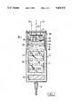
- FIG. 1is an elevational view, partially in section, of a portable terminal having bar code scanning accessory on an end of a handle having a manual data entry (keypad) and data processing unit, the terminal being shown as an integrated assembly;
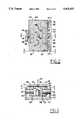
- FIG. 2is a plan view of the scan engine module shown in FIG. 1;
- FIG. 3is a sectional view taken along the line 3--3 in FIG. 2;
- FIG. 4is a view of the scan engine module with the optical receptor, its light collector and its support removed to show the components there below, the view being taken generally along the line 4--4 in FIG. 3;
- FIG. 5is an end view taken along the line 5--5 in FIG. 2;
- FIG. 6is a side view taken along the line 6--6 in FIG. 2;
- FIG. 7is a view similar to FIG. 6 with a flexural support of design different than that used in the scan engine module of FIGS. 1 through 6;
- FIG. 8is top view of an optical receptor of the scan engine module shown in FIGS. 1-6, which is the same as in FIG. 7 except that the laser diode is in the center rather than below the receiptor in the FIG. 7 embodiment;
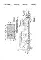
- FIG. 9is a fragmentary sectional view of the receptor taken along the line 9--9 in FIG. 8.
- a portable transaction terminal 14having a housing 12 providing a handle, a bar code scanning reader, provided in principal part by a scan engine module (a scanning accessory) 13 and a data entry, processing and display terminal 20.
- the terminalhas a keyboard 21 and a display 22 on one surface of the housing of the terminal which provides the handle 12.
- a bracket 26has connector, which may be provided by techniques for molding interconnections wherein resins capable of being treated so as to accept conductive material by plating or electrodeposition, interconnects electrically the scanning accessory 13 to electronic circuits on a printer circuit board 30 in the terminal 14 which powers the scanning accessory and decodes and processes the bar code data read by the scanning accessory.
- connectionsmay be provided by optical links; e.g., optos such as light emitters (LEDS) and photodetectors on opposite sides of an interface 16 between a receptacle 29 in the housing 12, accommodating the scan engine module 28 which provides the scanning accessory of the terminal 14.
- a window 41 at the front end of the housing 12covers the receptacle 29.
- a scan beam 40is projected to the bar code through the window (a transmissive material plate) which also provides a port for the return light (represented by rays 43) from the code.
- the scan engine 28is attached by the connector on the bracket 26 and defines an integral miniaturized scan engine module.
- the circuit board 30below the bracket 26 is the circuit board 30 and a battery (not shown).
- the batteryis optional, if power for operating the scan engine is from an external terminal, which is not shown, which is connected to the housing 12 by way of a cable 34.
- This cablehas leads for signals which are obtained in response to light detected from bar codes which are scanned by the engine 28.
- Leads from the circuit board 30(carrying signals from the processing unit of the terminal) also are connected to external equipment via the cable 34. These signal carrying leads to the terminal 14 and in the signal cable 34 may be connected in parallel.
- the handle 12may have a trigger (not shown) which operates a switch connected to the circuit board for enabling power to be applied to a laser diode and to a drive mechanism of the scan engine which causes the light beam from the scan engine to scan across the code.
- the readermay have means for automatically enabling the scan engine when an object on which a bar code is disposed is sensed, as for example described in U.S. Pat. No. 5,237,161 issued Aug. 17, 1993 and application Ser. No. 786,147 filed Oct. 31, 1991 in the name of Scott Grodevant and assigned to the same assignee as this application, now U.S. Pat. NO. 5,260,554 , issued Nov. 11, 1993 .
- the scan beam 40passes through the window or port 41 in the housing 12 in the direction of the code. Illumination from the code in response to this scanning beam is incident on an optical receptor or optic which includes a light collector 42 of the scan engine module 28.
- This collector and the semiconductor laser light source(laser diode 44) are mounted for conjoint oscillatory movement in flexures 46 and 48 which define a pivotal axis between foot members 50 and 52 extending from the base of a support 54 which is fixedly and stationarily mounted on the bracket 26. See also FIG. 3.
- the scan engine 28thus, provides a laser light beam 40 which scans the code and translates the illumination received upon scanning from the code into signals representing the code which are then processed in circuitry on the circuit board 30 and forwarded to the display 22 or to another external terminal or other bar code signal utilization equipment which is connected to the handle by the cable 34.
- the circuitry on circuit board 30may produce signals to initiate scanning by the scan engine module and to terminate scanning when a symbol is decoded or a period of time has elapsed. This circuitry may be of the type discussed in U.S. Pat. No. 5,200,597 issued Apr. 6, 1993to Eastman et and U.S. Pat. No. 5,237,161 and application Ser. No. 07/786,147 referred to above.
- the terminal 14 and the bar code scanner accessory 13provides an integrated portable transaction terminal which the operator can hold in one hand by the handle and enter data with the other hand on the keyboard 21. This data is processed in the computerized data handling circuitry of the terminal 14. The data may be held in memory in the terminal 14 for later read out and/or displayed on the display 22.
- the terminal unitmay also contain a transmitter and receiver to communicate data to and from a host computer via a wire or wireless link. Other facilities such as good read signals (audible or visual) may be provided.
- the handle unitmay also be self-contained and the display 22 is operable to show visually the bar codes which are read or messages from the host computer.
- the scan engine 28which is shown in FIG. 1 and in greater detail in FIGS. 2 through 6 or FIG. 7 is of the type presently preferred for use in the portable transaction terminal 14.
- the light receptor/collector optic 42is also shown in FIGS. 8 and 9.
- the flexures 46 and 48may be of the type shown in the above-referenced U.S. Pat. No. 5,015,831. They include members which provide circuit paths or traces of conductive material carrying signals from the receptor 42 as well as lines to the laser diode 44 (plus 5 volts and ground) which apply power to the laser diode. These circuit path members may, when the flexures are plastic, be molded in strips of plated conductive material integral with the flexures.
- a support for the laser diode 44 and the receptor 42is provided by the support blocks 56 and 58. These support blocks are connected to the flexures 46 and 48 along one side thereof and also to lower and upper circuit boards 60 and 62.
- the lower circuit board 60which may be a planar board, as illustrated, or a formed molded plated conductive material, carries the laser diode 44 and its control power and ground signals to circuit paths in the flexures either directly or via circuit board 62. These circuit paths may be in either or both of the flexures 46 and 48.
- the upper circuit board 62supports the optical collector (part of the electro-optical receptor 42). There may be an optical via, such as a hole 64, in the upper board 62 through which the beam 40 from the laser diode 44 projects on its way to the code (See FIG. 1). There may also be a hole in the optical collector in alignment with the hole 64.
- the collector 42which is a transparent thin glass or plastic plate 65 having a pair of sets of grating rings 66 and 67 (or ring gratings).
- the plateprovides the substrate for the gratings 66 and 67, as well as a light guide.
- Another type of optical viamay be provided by a section 69 of the plate 65 where the grating lines are removed. This area is an area in alignment with the beam and through which the beam 40 passes.
- the plate 65forms a light guide as seen in FIG. 9.
- the gratings 66 and 67may be blazed gratings or may be a transmission grating of the holographic type wherein the lines are internal, but preferably near the back or face 71 of the collector plate 65 (which faces away from the end of scan module which faces the code i.e. in a direction opposite to the direction of propagation of the scan beam 40). These ring gratings are sometimes called kineforms but are more descriptively called diffractive axicons.
- each grating lens 66 and 67At the center of each grating lens 66 and 67 are holes 81 containing photodetectors 68 and 73. Each photodetector may be a photodiode or phototransistor.
- the grating linesare essentially circles around the photodetectors 68 and 73.
- the forward face of the collector plate 65has a coating 75 of thin film materials which provides an incidence angle dependent reflector; being transmissive to light at small incidence angles (about up to 10° measured in air) which is the incidence angle of most of the return light from the code, while being reflective of the light incident at greater angles (effectively as in a beam splitter) which constitutes the light diffracted at the ring gratings 66 and 67, as shown in FIG. 9, e.g. about 30° or greater incidence angles, measured in the plate 65.
- Incident lightis directed towards the center of each grating, thereby limiting distance the light has to travel within the substrate and limit the interactions with the grating.
- a portion of the lightis in the first diffraction order and some in the second.
- the light in the first orderis reflected back towards the ring gratings 66 and 67 by the thin film coating 75 on the forward (code facing) surface of the collector plate 65.
- the majority of lightis in the second diffraction order of the incident light, which sends the light in the substrate to concentrators 91 and 93 situated over the detectors.
- the concentratorsare annular, and specifically circularly symmetric parabolic surfaces in the center of each grating 66 and 67 which focuses the light down to the detectors 68 and 73 located on the circuit board 62 below the gratings.
- an electromagnetic driverhaving coils 74 and 76 depending from the upper board 62.
- Pole pieces 78 and 80concentrate the electromagnetic field and provide attraction or repulsion to permanent magnets 82 and 84 which are in electro-magnetically coupled relationship with the coils.
- This motioncauses the scan beam 40 to scan across the code.
- Connectionsare provided in the board 62 from the circuits 72 and 77.
- circuitshave components which switch current to the coils 74 and 76 to cause the oscillation of the laser diode 44 and the receptor 42 about the pivotal axis defined by the flexures 46 and 48.
- the receptor 42oscillates conjointly (together) with the laser diode since they are tied together by a common support structure.
- FIG. 7there is shown a scan engine module 90 which is similar in many respects to the scan engine module 28, and like parts are identified by like reference numerals. Only one circuit board 62 is used. The laser diode is mounted on the board through an opening in the substrate 65 and its grating. The flexures are provided by crossed springs of a design similar to those discussed in the above-referenced U.S. Pat. NO. 5,115,120.
- Blocks 92 and 94may be molded plates of conductive plastic material to provide conductive paths from the flexures to the circuit board 62.
- the miniature size of a typical collectormay be 2.0 mm in thickness between the forward face having the coating 75 and the rear face 71 on the board 62.
- the thickness of the board 62may be 0.51 mm.
- the width of the collector between its longitudinal edges 101 and 103may be 18 mm and its length may be 36 mm. These sizes are typical and have been found to provide collection of bar code return light about the same as the PSC Inc. model 5300 Bar Code Reader which is shown in the Eastman et al U.S. Pat. No. 5,200,597 (referenced above).
- the gratingmay be blazed grooves forming the rings; the grooves being of sawtooth shape. Typically they may have a constant pitch of 0.9 micrometers ( ⁇ m) and inclined at about 25° .
- FIG. 9shows how typical incident rays are collected and concentrated and directed to the photodetectors 68 and 73 at the center of each grating 66 and 67.
- the two gratings 66 and 67are disposed symmetrically about a line 49 which bisects the rectangular plate 65 such that the grating rings intersect, forming cusps at 47.
- the grating collector axiconslocally diffract the light returned by the bar code according to the well known diffraction equation (here written in direction cosine space): ##EQU1##
- mis the diffraction order.
- ⁇is incident wave length.
- pis the diffraction grating pitch.
- ⁇is the angle of the local grating groove tangent.
- ⁇ and ⁇are the incident direction cosines.
- ⁇ 1 m and ⁇ 1 mare the diffracted direction cosines of order m.
- the grating pitch pis chosen so that light diffracted into the first order is incident at a high enough angle to be reflected by coating 75. Note that the embodiment shown in FIG. 9 has a constant pitch, and thus, all 2nd order rays are parallel.
- the grating pitchmay be varied in order to vary collection efficiency with distance from the scanner to the bar-code (range).
Landscapes
- Physics & Mathematics (AREA)
- Engineering & Computer Science (AREA)
- Electromagnetism (AREA)
- General Physics & Mathematics (AREA)
- Artificial Intelligence (AREA)
- Toxicology (AREA)
- General Health & Medical Sciences (AREA)
- Computer Vision & Pattern Recognition (AREA)
- Health & Medical Sciences (AREA)
- Theoretical Computer Science (AREA)
- Optics & Photonics (AREA)
- Mechanical Optical Scanning Systems (AREA)
- Cash Registers Or Receiving Machines (AREA)
- Input From Keyboards Or The Like (AREA)
Abstract
Description
Claims (34)
Priority Applications (11)
| Application Number | Priority Date | Filing Date | Title |
|---|---|---|---|
| US08/138,313US5422472A (en) | 1992-12-04 | 1993-10-18 | Optical symbol (bar code) reading systems having an electro-optic receptor with embedded grating rings |
| ZA947356AZA947356B (en) | 1993-10-18 | 1994-09-21 | Optical symbol (bar code) reading systems having an electro-optic receptor with embedded grating rings |
| US08/320,888US5714750A (en) | 1992-12-04 | 1994-10-05 | Bar code scanning and reading apparatus and diffractive light collection device suitable for use therein. |
| TW083109331ATW281752B (en) | 1993-10-18 | 1994-10-07 | |
| JP7512107AJPH09503878A (en) | 1993-10-18 | 1994-10-14 | Optical symbol (bar code) reading system and device |
| BR9407854ABR9407854A (en) | 1993-10-18 | 1994-10-14 | Scanning accessory scanning machine and electro-optical receiver |
| PCT/US1994/011738WO1995011490A1 (en) | 1993-10-18 | 1994-10-14 | Optical symbol (bar code) reading systems and devices |
| EP94931864AEP0724752A4 (en) | 1993-10-18 | 1994-10-14 | Optical symbol (bar code) reading systems and devices |
| CA002174437ACA2174437A1 (en) | 1993-10-18 | 1994-10-14 | Optical symbol (bar code) reading systems and devices |
| AU80789/94AAU684569B2 (en) | 1993-10-18 | 1994-10-14 | Optical symbol (bar code) reading systems and devices |
| US08/332,205US5629510A (en) | 1992-12-04 | 1994-10-31 | Bar code scanning and reading apparatus with an oscillating scanning engine |
Applications Claiming Priority (2)
| Application Number | Priority Date | Filing Date | Title |
|---|---|---|---|
| US98537192A | 1992-12-04 | 1992-12-04 | |
| US08/138,313US5422472A (en) | 1992-12-04 | 1993-10-18 | Optical symbol (bar code) reading systems having an electro-optic receptor with embedded grating rings |
Related Parent Applications (1)
| Application Number | Title | Priority Date | Filing Date |
|---|---|---|---|
| US98537192AContinuation-In-Part | 1992-12-04 | 1992-12-04 |
Related Child Applications (1)
| Application Number | Title | Priority Date | Filing Date |
|---|---|---|---|
| US08/320,888Continuation-In-PartUS5714750A (en) | 1992-12-04 | 1994-10-05 | Bar code scanning and reading apparatus and diffractive light collection device suitable for use therein. |
Publications (1)
| Publication Number | Publication Date |
|---|---|
| US5422472Atrue US5422472A (en) | 1995-06-06 |
Family
ID=22481476
Family Applications (1)
| Application Number | Title | Priority Date | Filing Date |
|---|---|---|---|
| US08/138,313Expired - LifetimeUS5422472A (en) | 1992-12-04 | 1993-10-18 | Optical symbol (bar code) reading systems having an electro-optic receptor with embedded grating rings |
Country Status (9)
| Country | Link |
|---|---|
| US (1) | US5422472A (en) |
| EP (1) | EP0724752A4 (en) |
| JP (1) | JPH09503878A (en) |
| AU (1) | AU684569B2 (en) |
| BR (1) | BR9407854A (en) |
| CA (1) | CA2174437A1 (en) |
| TW (1) | TW281752B (en) |
| WO (1) | WO1995011490A1 (en) |
| ZA (1) | ZA947356B (en) |
Cited By (47)
| Publication number | Priority date | Publication date | Assignee | Title |
|---|---|---|---|---|
| WO1996011450A1 (en)* | 1994-10-05 | 1996-04-18 | Psc Inc. | Bar code scanning and reading apparatus and diffractive light collection device suitable for use therein |
| US6415981B1 (en)* | 1998-11-26 | 2002-07-09 | Denso Corporation | Optical reader with reduced-sized optical sensor configuration |
| US6523753B2 (en)* | 1998-11-10 | 2003-02-25 | Symbol Technologies, Inc. | System for reading barcode symbols |
| US6533183B2 (en)* | 2000-05-03 | 2003-03-18 | Novo Nordisk A/S | Coding of cartridges for an injection device |
| US20040136069A1 (en)* | 1992-03-30 | 2004-07-15 | Symbol Technologies, Inc., A Delaware Corporation | Athermalized plastic lens |
| US20040210759A1 (en)* | 2002-01-11 | 2004-10-21 | Fitch Timothy R. | Transaction terminal |
| US6811085B2 (en)* | 2001-10-26 | 2004-11-02 | Symbol Technologies, Inc. | Miniature imager |
| US20050039052A1 (en)* | 2002-01-11 | 2005-02-17 | O'donnell James | Ease of use transaction terminal |
| US20050087601A1 (en)* | 2003-10-24 | 2005-04-28 | Gerst Carl W.Iii | Light pipe illumination system and method |
| US20060131419A1 (en)* | 2004-12-21 | 2006-06-22 | Laurens Nunnink | Low profile illumination for direct part mark readers |
| US7066392B1 (en)* | 2005-06-17 | 2006-06-27 | Hsien-Rong Liang | Multimedia connector reader device |
| US20060164541A1 (en)* | 2005-01-27 | 2006-07-27 | Olmstead Bryan L | Rolling-reset imager with optical filter |
| US20060164736A1 (en)* | 2005-01-27 | 2006-07-27 | Olmstead Bryan L | Imaging system with a lens having increased light collection efficiency and a deblurring equalizer |
| US20060178637A1 (en)* | 2000-08-10 | 2006-08-10 | Michael Eilersen | Support for a cartridge for transferring an electronically readable item of information from the cartridge to an electronic circuit |
| US20070090193A1 (en)* | 2005-10-24 | 2007-04-26 | Laurens Nunnink | Integrated illumination assembly for symbology reader |
| US20070119947A1 (en)* | 2005-10-20 | 2007-05-31 | Blake Robert E | Scanner flipper integrity indicator |
| US20080156880A1 (en)* | 2006-12-29 | 2008-07-03 | Symbol Technologies, Inc. | Imaging-based reader having light guided illumination |
| US7451917B2 (en) | 2002-01-11 | 2008-11-18 | Hand Held Products, Inc. | Transaction terminal comprising imaging module |
| US20080287865A1 (en)* | 2005-05-10 | 2008-11-20 | Novo Nordisk A/S | Injection Device Comprising An Optical Sensor |
| US20080290170A1 (en)* | 2007-05-24 | 2008-11-27 | Blake Robert E | Scanner switched to active state by sensed movement in quiescent scanning mechanism |
| WO2008148029A1 (en)* | 2007-05-25 | 2008-12-04 | Molex Incorporated | Heat sink for a heat generator and a power source |
| US7479946B2 (en) | 2002-01-11 | 2009-01-20 | Hand Held Products, Inc. | Ergonomically designed multifunctional transaction terminal |
| US20090051027A1 (en)* | 2000-03-13 | 2009-02-26 | Megica Corporation | Method of Manufacture and Identification of Semiconductor Chip Marked For Identification with Internal Marking Indicia and Protection Thereof by Non-black Layer and Device Produced Thereby |
| US20090076460A1 (en)* | 2005-09-22 | 2009-03-19 | Novo Nordisk A/S | Device And Method For Contact Free Absolute Position Determination |
| US20090088701A1 (en)* | 2006-03-20 | 2009-04-02 | Novo Nordisk A/S | Contact Free Reading of Cartridge Identification Codes |
| US20090103862A1 (en)* | 2007-10-23 | 2009-04-23 | Bratkovski Alexandre M | Waveguide system with diffracting structure |
| US7614545B2 (en) | 2003-03-24 | 2009-11-10 | Novo Nordisk A/S | Electronic marking of a medication cartridge |
| US7614563B1 (en)* | 2005-12-29 | 2009-11-10 | Cognex Technology And Investment Corporation | System and method for providing diffuse illumination in a symbology reader |
| US20100012735A1 (en)* | 2000-08-10 | 2010-01-21 | Novo Nordisk A/S | Support for a Cartridge for Transferring an Electronically Readable Item of Information from the Cartridge to an Electronic Circuit |
| US20100025469A1 (en)* | 2003-10-24 | 2010-02-04 | Gerst Iii Carl W | Method and apparatus for providing omnidirectional lighting in a scanning device |
| US20100090006A1 (en) | 2002-01-11 | 2010-04-15 | Hand Held Products, Inc. | Terminal including imaging assembly |
| US20100106100A1 (en)* | 2007-03-21 | 2010-04-29 | Novo Nordisk A/S | Medical delivery system having container recognition and container for use with the medical delivery system |
| US20100194537A1 (en)* | 2007-06-09 | 2010-08-05 | Novo Nordisk A/S | Contact free reading of reservoir identification codes |
| US20110069365A1 (en)* | 2009-09-23 | 2011-03-24 | Metrologic Instruments, Inc. | Scan element for use in scanning light and method of making the same |
| US8049519B2 (en) | 2006-04-26 | 2011-11-01 | Novo Nordisk A/S | Contact free absolute position determination of a moving element in a medication delivery device |
| US8294969B2 (en) | 2009-09-23 | 2012-10-23 | Metrologic Instruments, Inc. | Scan element for use in scanning light and method of making the same |
| US8390909B2 (en) | 2009-09-23 | 2013-03-05 | Metrologic Instruments, Inc. | Molded elastomeric flexural elements for use in a laser scanning assemblies and scanners, and methods of manufacturing, tuning and adjusting the same |
| US8746563B2 (en) | 2012-06-10 | 2014-06-10 | Metrologic Instruments, Inc. | Laser scanning module with rotatably adjustable laser scanning assembly |
| US8915439B2 (en) | 2012-02-06 | 2014-12-23 | Metrologic Instruments, Inc. | Laser scanning modules embodying silicone scan element with torsional hinges |
| US8994382B2 (en) | 2006-04-12 | 2015-03-31 | Novo Nordisk A/S | Absolute position determination of movably mounted member in medication delivery device |
| US9070031B2 (en) | 2003-10-24 | 2015-06-30 | Cognex Technology And Investment Llc | Integrated illumination assembly for symbology reader |
| US9186465B2 (en) | 2008-11-06 | 2015-11-17 | Novo Nordisk A/S | Electronically assisted drug delivery device |
| US9292724B1 (en) | 2004-12-16 | 2016-03-22 | Cognex Corporation | Hand held symbology reader illumination diffuser with aimer optics |
| US9361495B2 (en) | 2004-12-16 | 2016-06-07 | Cognex Technology And Investment Llc | Hand held symbology reader illumination diffuser |
| US9536124B1 (en) | 2003-10-24 | 2017-01-03 | Cognex Corporation | Integrated illumination assembly for symbology reader |
| US9950117B2 (en) | 2009-02-13 | 2018-04-24 | Novo Nordisk A/S | Medical device and cartridge |
| US10198647B2 (en) | 2015-09-25 | 2019-02-05 | Datalogic IP Tech, S.r.l. | Compact imaging module with range finder |
Families Citing this family (1)
| Publication number | Priority date | Publication date | Assignee | Title |
|---|---|---|---|---|
| TWM510819U (en) | 2015-05-20 | 2015-10-21 | hong-jun Xu | Universal open-end wrench |
Citations (9)
| Publication number | Priority date | Publication date | Assignee | Title |
|---|---|---|---|---|
| US3763372A (en)* | 1967-07-13 | 1973-10-02 | Inventors & Investors Inc | Zone plate optics monolithically integrated with photoelectric elements |
| US5015831A (en)* | 1988-11-07 | 1991-05-14 | Photographic Sciences Corporation | Scan modules for bar code readers and the like in which scan elements are flexurally supported |
| US5115120A (en)* | 1990-06-26 | 1992-05-19 | Photographic Sciences Corporation | Scan modules for bar code readers and in which scan elements are flexurally supported |
| US5144120A (en)* | 1988-05-11 | 1992-09-01 | Symbol Technologies, Inc. | Mirrorless scanners with movable laser, optical and sensor components |
| US5200597A (en)* | 1991-02-07 | 1993-04-06 | Psc, Inc. | Digitally controlled system for scanning and reading bar codes |
| US5208449A (en)* | 1991-09-09 | 1993-05-04 | Psc, Inc. | Portable transaction terminal |
| US5212372A (en)* | 1991-09-09 | 1993-05-18 | Psc, Inc. | Portable transaction terminal for optical and key entry of data without keyboards and manually actuated scanners |
| US5237161A (en)* | 1991-06-05 | 1993-08-17 | Psc, Inc. | System for automatically reading symbols, such as bar codes, on objects which are placed in the detection zone of a symbol reading unit, such as a bar code scanner |
| US5268985A (en)* | 1991-07-30 | 1993-12-07 | Nippondenso Co., Ltd. | Light-guiding device having a hologram layer |
Family Cites Families (4)
| Publication number | Priority date | Publication date | Assignee | Title |
|---|---|---|---|---|
| US4945527A (en)* | 1987-09-30 | 1990-07-31 | Fuji Photo Film Co., Ltd. | Optical pickup apparatus for detection of focusing error, tracking error, and information |
| US5254844A (en)* | 1988-05-11 | 1993-10-19 | Symbol Technologies, Inc. | Mirrorless scanners with movable laser, optical and sensor components |
| ATE98795T1 (en)* | 1988-09-30 | 1994-01-15 | Landis & Gyr Business Support | DIFFRACTION ELEMENT. |
| WO1994014136A1 (en)* | 1992-12-04 | 1994-06-23 | Psc, Inc. | Optical symbol (bar code) reading systems and devices |
- 1993
- 1993-10-18USUS08/138,313patent/US5422472A/ennot_activeExpired - Lifetime
- 1994
- 1994-09-21ZAZA947356Apatent/ZA947356B/enunknown
- 1994-10-07TWTW083109331Apatent/TW281752B/zhactive
- 1994-10-14BRBR9407854Apatent/BR9407854A/ennot_activeApplication Discontinuation
- 1994-10-14WOPCT/US1994/011738patent/WO1995011490A1/ennot_activeApplication Discontinuation
- 1994-10-14EPEP94931864Apatent/EP0724752A4/ennot_activeCeased
- 1994-10-14AUAU80789/94Apatent/AU684569B2/ennot_activeExpired - Fee Related
- 1994-10-14CACA002174437Apatent/CA2174437A1/ennot_activeAbandoned
- 1994-10-14JPJP7512107Apatent/JPH09503878A/enactivePending
Patent Citations (9)
| Publication number | Priority date | Publication date | Assignee | Title |
|---|---|---|---|---|
| US3763372A (en)* | 1967-07-13 | 1973-10-02 | Inventors & Investors Inc | Zone plate optics monolithically integrated with photoelectric elements |
| US5144120A (en)* | 1988-05-11 | 1992-09-01 | Symbol Technologies, Inc. | Mirrorless scanners with movable laser, optical and sensor components |
| US5015831A (en)* | 1988-11-07 | 1991-05-14 | Photographic Sciences Corporation | Scan modules for bar code readers and the like in which scan elements are flexurally supported |
| US5115120A (en)* | 1990-06-26 | 1992-05-19 | Photographic Sciences Corporation | Scan modules for bar code readers and in which scan elements are flexurally supported |
| US5200597A (en)* | 1991-02-07 | 1993-04-06 | Psc, Inc. | Digitally controlled system for scanning and reading bar codes |
| US5237161A (en)* | 1991-06-05 | 1993-08-17 | Psc, Inc. | System for automatically reading symbols, such as bar codes, on objects which are placed in the detection zone of a symbol reading unit, such as a bar code scanner |
| US5268985A (en)* | 1991-07-30 | 1993-12-07 | Nippondenso Co., Ltd. | Light-guiding device having a hologram layer |
| US5208449A (en)* | 1991-09-09 | 1993-05-04 | Psc, Inc. | Portable transaction terminal |
| US5212372A (en)* | 1991-09-09 | 1993-05-18 | Psc, Inc. | Portable transaction terminal for optical and key entry of data without keyboards and manually actuated scanners |
Cited By (94)
| Publication number | Priority date | Publication date | Assignee | Title |
|---|---|---|---|---|
| US7038853B2 (en)* | 1992-03-30 | 2006-05-02 | Symbol Technlogies, Inc. | Athermalized plastic lens |
| US20040136069A1 (en)* | 1992-03-30 | 2004-07-15 | Symbol Technologies, Inc., A Delaware Corporation | Athermalized plastic lens |
| US5714750A (en)* | 1992-12-04 | 1998-02-03 | Psc Inc. | Bar code scanning and reading apparatus and diffractive light collection device suitable for use therein. |
| GB2308678A (en)* | 1994-10-05 | 1997-07-02 | Psc Inc | Bar code scanning and reading apparatus and diffractive light collection device suitable for use therein |
| GB2308678B (en)* | 1994-10-05 | 1998-09-30 | Psc Inc | Bar code scanning and reading apparatus and diffractive light collection device suitable for use therein |
| WO1996011450A1 (en)* | 1994-10-05 | 1996-04-18 | Psc Inc. | Bar code scanning and reading apparatus and diffractive light collection device suitable for use therein |
| US6523753B2 (en)* | 1998-11-10 | 2003-02-25 | Symbol Technologies, Inc. | System for reading barcode symbols |
| US6415981B1 (en)* | 1998-11-26 | 2002-07-09 | Denso Corporation | Optical reader with reduced-sized optical sensor configuration |
| US20090051027A1 (en)* | 2000-03-13 | 2009-02-26 | Megica Corporation | Method of Manufacture and Identification of Semiconductor Chip Marked For Identification with Internal Marking Indicia and Protection Thereof by Non-black Layer and Device Produced Thereby |
| US6533183B2 (en)* | 2000-05-03 | 2003-03-18 | Novo Nordisk A/S | Coding of cartridges for an injection device |
| US20100012735A1 (en)* | 2000-08-10 | 2010-01-21 | Novo Nordisk A/S | Support for a Cartridge for Transferring an Electronically Readable Item of Information from the Cartridge to an Electronic Circuit |
| US7621456B2 (en) | 2000-08-10 | 2009-11-24 | Novo Nordisk A/S | Support for a cartridge for transferring an electronically readable item of information from the cartridge to an electronic circuit |
| US7922096B2 (en) | 2000-08-10 | 2011-04-12 | Novo Nordisk A/S | Support for a cartridge for transferring an electronically readable item of information from the cartridge to an electronic circuit |
| US20060178637A1 (en)* | 2000-08-10 | 2006-08-10 | Michael Eilersen | Support for a cartridge for transferring an electronically readable item of information from the cartridge to an electronic circuit |
| US6811085B2 (en)* | 2001-10-26 | 2004-11-02 | Symbol Technologies, Inc. | Miniature imager |
| US20100090006A1 (en) | 2002-01-11 | 2010-04-15 | Hand Held Products, Inc. | Terminal including imaging assembly |
| US7472825B2 (en) | 2002-01-11 | 2009-01-06 | Hand Held Products, Inc. | Transaction terminal |
| US20040210759A1 (en)* | 2002-01-11 | 2004-10-21 | Fitch Timothy R. | Transaction terminal |
| US8544737B2 (en) | 2002-01-11 | 2013-10-01 | Hand Held Products, Inc. | Terminal including imaging assembly |
| US7748620B2 (en) | 2002-01-11 | 2010-07-06 | Hand Held Products, Inc. | Transaction terminal including imaging module |
| US8561895B2 (en) | 2002-01-11 | 2013-10-22 | Hand Held Products, Inc. | Terminal including imaging assembly |
| US20050039052A1 (en)* | 2002-01-11 | 2005-02-17 | O'donnell James | Ease of use transaction terminal |
| US7451917B2 (en) | 2002-01-11 | 2008-11-18 | Hand Held Products, Inc. | Transaction terminal comprising imaging module |
| US9734493B2 (en) | 2002-01-11 | 2017-08-15 | Hand Held Products, Inc. | Terminal including imaging assembly |
| US8967468B2 (en) | 2002-01-11 | 2015-03-03 | Hand Held Products, Inc. | Terminal including imaging assembly |
| US7479946B2 (en) | 2002-01-11 | 2009-01-20 | Hand Held Products, Inc. | Ergonomically designed multifunctional transaction terminal |
| US7614545B2 (en) | 2003-03-24 | 2009-11-10 | Novo Nordisk A/S | Electronic marking of a medication cartridge |
| US9298960B2 (en) | 2003-10-24 | 2016-03-29 | Cognex Corporation | Method and apparatus for providing omnidirectional lighting in a scanning device |
| US8061614B2 (en) | 2003-10-24 | 2011-11-22 | Cognex Technology And Investment Corporation | Light pipe illumination system and method |
| US8061613B2 (en) | 2003-10-24 | 2011-11-22 | Cognex Technology And Investment Corporation | Method and apparatus for providing omnidirectional lighting in a scanning device |
| US8282000B2 (en) | 2003-10-24 | 2012-10-09 | Cognex Technology And Investment Corporation | Method and apparatus for providing omnidirectional lighting in a scanning device |
| US9070031B2 (en) | 2003-10-24 | 2015-06-30 | Cognex Technology And Investment Llc | Integrated illumination assembly for symbology reader |
| US7823783B2 (en) | 2003-10-24 | 2010-11-02 | Cognex Technology And Investment Corporation | Light pipe illumination system and method |
| US8770483B2 (en) | 2003-10-24 | 2014-07-08 | Cognex Technology And Investment Corporation | Light pipe illumination system and method |
| US8740078B2 (en) | 2003-10-24 | 2014-06-03 | Cognex Technology And Investment Corporation | Method and apparatus for providing omnidirectional lighting in a scanning device |
| US9329332B2 (en) | 2003-10-24 | 2016-05-03 | Cognex Corporation | Light pipe illumination system and method |
| US8342405B2 (en) | 2003-10-24 | 2013-01-01 | Cognex Technology And Investment Corporation | Light pipe illumination system and method |
| US20050087601A1 (en)* | 2003-10-24 | 2005-04-28 | Gerst Carl W.Iii | Light pipe illumination system and method |
| US9536124B1 (en) | 2003-10-24 | 2017-01-03 | Cognex Corporation | Integrated illumination assembly for symbology reader |
| US20100025469A1 (en)* | 2003-10-24 | 2010-02-04 | Gerst Iii Carl W | Method and apparatus for providing omnidirectional lighting in a scanning device |
| US9292724B1 (en) | 2004-12-16 | 2016-03-22 | Cognex Corporation | Hand held symbology reader illumination diffuser with aimer optics |
| US9361495B2 (en) | 2004-12-16 | 2016-06-07 | Cognex Technology And Investment Llc | Hand held symbology reader illumination diffuser |
| US9495573B2 (en) | 2004-12-21 | 2016-11-15 | Cognex Technology And Investment Corporation | Low profile illumination for direct part mark readers |
| US8672227B2 (en) | 2004-12-21 | 2014-03-18 | Cognex Technology And Investment Corporation | Low profile illumination for direct part mark readers |
| US7823789B2 (en) | 2004-12-21 | 2010-11-02 | Cognex Technology And Investment Corporation | Low profile illumination for direct part mark readers |
| US20060131419A1 (en)* | 2004-12-21 | 2006-06-22 | Laurens Nunnink | Low profile illumination for direct part mark readers |
| US7215493B2 (en) | 2005-01-27 | 2007-05-08 | Psc Scanning, Inc. | Imaging system with a lens having increased light collection efficiency and a deblurring equalizer |
| US20060164736A1 (en)* | 2005-01-27 | 2006-07-27 | Olmstead Bryan L | Imaging system with a lens having increased light collection efficiency and a deblurring equalizer |
| US7499090B2 (en) | 2005-01-27 | 2009-03-03 | Datalogic Scanning, Inc. | Rolling-reset imager with optical filter |
| US8134621B2 (en) | 2005-01-27 | 2012-03-13 | Datalogic ADC, Inc. | Rolling-reset imager |
| USRE43089E1 (en) | 2005-01-27 | 2012-01-10 | Datalogic Scanning, Inc. | Imaging system with a lens having increased light collection efficiency and a deblurring equalizer |
| US20060164541A1 (en)* | 2005-01-27 | 2006-07-27 | Olmstead Bryan L | Rolling-reset imager with optical filter |
| US20080287865A1 (en)* | 2005-05-10 | 2008-11-20 | Novo Nordisk A/S | Injection Device Comprising An Optical Sensor |
| US9522238B2 (en) | 2005-05-10 | 2016-12-20 | Novo Nordisk A/S | Injection device comprising an optical sensor |
| US8771238B2 (en) | 2005-05-10 | 2014-07-08 | Novo Nordisk A/S | Injection device comprising an optical sensor |
| US8197449B2 (en) | 2005-05-10 | 2012-06-12 | Novo Nordisk A/S | Injection device comprising an optical sensor |
| US7066392B1 (en)* | 2005-06-17 | 2006-06-27 | Hsien-Rong Liang | Multimedia connector reader device |
| US20090076460A1 (en)* | 2005-09-22 | 2009-03-19 | Novo Nordisk A/S | Device And Method For Contact Free Absolute Position Determination |
| US8638108B2 (en) | 2005-09-22 | 2014-01-28 | Novo Nordisk A/S | Device and method for contact free absolute position determination |
| US8002183B2 (en) | 2005-10-20 | 2011-08-23 | Metrologic Instruments, Inc. | Scanner flipper integrity indicator |
| US20070119947A1 (en)* | 2005-10-20 | 2007-05-31 | Blake Robert E | Scanner flipper integrity indicator |
| US7874487B2 (en) | 2005-10-24 | 2011-01-25 | Cognex Technology And Investment Corporation | Integrated illumination assembly for symbology reader |
| US20070090193A1 (en)* | 2005-10-24 | 2007-04-26 | Laurens Nunnink | Integrated illumination assembly for symbology reader |
| US9405951B2 (en) | 2005-10-24 | 2016-08-02 | Cognex Technology And Investment Llc | Integrated illumination assembly for symbology reader |
| US7614563B1 (en)* | 2005-12-29 | 2009-11-10 | Cognex Technology And Investment Corporation | System and method for providing diffuse illumination in a symbology reader |
| US20090088701A1 (en)* | 2006-03-20 | 2009-04-02 | Novo Nordisk A/S | Contact Free Reading of Cartridge Identification Codes |
| US8608079B2 (en) | 2006-03-20 | 2013-12-17 | Novo Nordisk A/S | Contact free reading of cartridge identification codes |
| US8994382B2 (en) | 2006-04-12 | 2015-03-31 | Novo Nordisk A/S | Absolute position determination of movably mounted member in medication delivery device |
| US8049519B2 (en) | 2006-04-26 | 2011-11-01 | Novo Nordisk A/S | Contact free absolute position determination of a moving element in a medication delivery device |
| US7780088B2 (en)* | 2006-12-29 | 2010-08-24 | Symbol Technologies, Inc. | Imaging-based reader having light guided illumination |
| US20080156880A1 (en)* | 2006-12-29 | 2008-07-03 | Symbol Technologies, Inc. | Imaging-based reader having light guided illumination |
| US8348904B2 (en) | 2007-03-21 | 2013-01-08 | Novo Nordisk A/S | Medical delivery system having container recognition and container for use with the medical delivery system |
| US20100106100A1 (en)* | 2007-03-21 | 2010-04-29 | Novo Nordisk A/S | Medical delivery system having container recognition and container for use with the medical delivery system |
| US20080290170A1 (en)* | 2007-05-24 | 2008-11-27 | Blake Robert E | Scanner switched to active state by sensed movement in quiescent scanning mechanism |
| US7832641B2 (en) | 2007-05-24 | 2010-11-16 | Metrologic Instruments, Inc. | Scanner switched to active state by sensed movement in quiescent scanning mechanism |
| CN101765741B (en)* | 2007-05-25 | 2012-07-04 | 莫列斯公司 | Radiators for heating devices and power supplies |
| TWI414716B (en)* | 2007-05-25 | 2013-11-11 | Molex Inc | Method of manufacturing an interconnect device which forms a heat sink and electrical connections between a heat generating device and a power source |
| CN102638943A (en)* | 2007-05-25 | 2012-08-15 | 莫列斯公司 | Heat sink for a heat generator and a power source |
| US20080307646A1 (en)* | 2007-05-25 | 2008-12-18 | Victor Zaderej | Method of manufacturing an interconnect device which forms a heat sink and electrical connections between a heat generating device and a power source |
| US7992294B2 (en) | 2007-05-25 | 2011-08-09 | Molex Incorporated | Method of manufacturing an interconnect device which forms a heat sink and electrical connections between a heat generating device and a power source |
| WO2008148029A1 (en)* | 2007-05-25 | 2008-12-04 | Molex Incorporated | Heat sink for a heat generator and a power source |
| US20100194537A1 (en)* | 2007-06-09 | 2010-08-05 | Novo Nordisk A/S | Contact free reading of reservoir identification codes |
| US7546012B2 (en)* | 2007-10-23 | 2009-06-09 | Hewlett-Packard Development Company, L.P. | Waveguide system with diffracting structure |
| US20090103862A1 (en)* | 2007-10-23 | 2009-04-23 | Bratkovski Alexandre M | Waveguide system with diffracting structure |
| US9186465B2 (en) | 2008-11-06 | 2015-11-17 | Novo Nordisk A/S | Electronically assisted drug delivery device |
| US9950117B2 (en) | 2009-02-13 | 2018-04-24 | Novo Nordisk A/S | Medical device and cartridge |
| US8390909B2 (en) | 2009-09-23 | 2013-03-05 | Metrologic Instruments, Inc. | Molded elastomeric flexural elements for use in a laser scanning assemblies and scanners, and methods of manufacturing, tuning and adjusting the same |
| US8294969B2 (en) | 2009-09-23 | 2012-10-23 | Metrologic Instruments, Inc. | Scan element for use in scanning light and method of making the same |
| US20110069365A1 (en)* | 2009-09-23 | 2011-03-24 | Metrologic Instruments, Inc. | Scan element for use in scanning light and method of making the same |
| US8059324B2 (en) | 2009-09-23 | 2011-11-15 | Metrologic Instruments, Inc. | Scan element for use in scanning light and method of making the same |
| US9158951B2 (en) | 2012-02-06 | 2015-10-13 | Metrologic Instruments, Inc. | Laser scanning modules embodying silicone scan element with torsional hinges |
| US8915439B2 (en) | 2012-02-06 | 2014-12-23 | Metrologic Instruments, Inc. | Laser scanning modules embodying silicone scan element with torsional hinges |
| US8746563B2 (en) | 2012-06-10 | 2014-06-10 | Metrologic Instruments, Inc. | Laser scanning module with rotatably adjustable laser scanning assembly |
| US10198647B2 (en) | 2015-09-25 | 2019-02-05 | Datalogic IP Tech, S.r.l. | Compact imaging module with range finder |
Also Published As
| Publication number | Publication date |
|---|---|
| ZA947356B (en) | 1995-05-10 |
| EP0724752A4 (en) | 1999-01-13 |
| WO1995011490A1 (en) | 1995-04-27 |
| CA2174437A1 (en) | 1995-04-27 |
| AU684569B2 (en) | 1997-12-18 |
| BR9407854A (en) | 1997-05-20 |
| EP0724752A1 (en) | 1996-08-07 |
| AU8078994A (en) | 1995-05-08 |
| JPH09503878A (en) | 1997-04-15 |
| TW281752B (en) | 1996-07-21 |
Similar Documents
| Publication | Publication Date | Title |
|---|---|---|
| US5422472A (en) | Optical symbol (bar code) reading systems having an electro-optic receptor with embedded grating rings | |
| US5786585A (en) | Optical symbol (bar code) reading systems and devices | |
| EP0945819B1 (en) | One piece optical assembly for low cost optical scanner | |
| JP2732459B2 (en) | Scan module for barcode reader | |
| US6491222B1 (en) | Optical path design for scanning assembly in compact bar code readers | |
| US6257491B1 (en) | Packaged mirror including mirror travel stops | |
| US5629510A (en) | Bar code scanning and reading apparatus with an oscillating scanning engine | |
| EP0731417A2 (en) | Scan module for optical scanner | |
| US6527180B1 (en) | Compact dual optical and scan modules in bar code readers | |
| WO2007028562A2 (en) | Light concentrator for an optical code reader | |
| EP1308875B1 (en) | High speed laser scan module with folded beam path | |
| US6715685B2 (en) | Optical path design for scanning assembly in compact bar code readers | |
| JP2003315713A (en) | High-speed laser scanning module having reflection beam route | |
| US7017815B2 (en) | Compact externally-driven scanner | |
| RU95121626A (en) | SCANNING DEVICE AND DEVICE FOR OPTICAL RECOGNITION OF CHARACTERS, ELECTRO-OPTICAL RECEIVER (OPTIONS) |
Legal Events
| Date | Code | Title | Description |
|---|---|---|---|
| AS | Assignment | Owner name:PSC INC., NEW YORK Free format text:ASSIGNMENT OF ASSIGNORS INTEREST;ASSIGNORS:ZAVISLAN, JAMES M.;EASTMAN, JAY M.;QUINN, ANNA M.;REEL/FRAME:006749/0498 Effective date:19931015 | |
| STCF | Information on status: patent grant | Free format text:PATENTED CASE | |
| AS | Assignment | Owner name:FLEET BANK, NEW YORK Free format text:SECURITY AGREEMENT;ASSIGNORS:PSC, INC.;PSC ACQUISITION, INC.;SPECTRA-PHYSICS SCANNING SYSTEMS, INC.;AND OTHERS;REEL/FRAME:008133/0346 Effective date:19960712 | |
| FEPP | Fee payment procedure | Free format text:PAT HLDR NO LONGER CLAIMS SMALL ENT STAT AS SMALL BUSINESS (ORIGINAL EVENT CODE: LSM2); ENTITY STATUS OF PATENT OWNER: LARGE ENTITY | |
| FPAY | Fee payment | Year of fee payment:4 | |
| FPAY | Fee payment | Year of fee payment:8 | |
| SULP | Surcharge for late payment | Year of fee payment:7 | |
| REMI | Maintenance fee reminder mailed | ||
| AS | Assignment | Owner name:PSC INC., OREGON Free format text:RELEASE OF SECURITY INTEREST;ASSIGNOR:LJ SCANNER HOLDINGS, INC., AS SUCCESSOR IN INTEREST TO FLEET NATIONAL BANK (A/K/A FLEET BANK), AS ADMINISTRATIVE AGENT;REEL/FRAME:014926/0809 Effective date:20031223 Owner name:WELLS FARGO FOOTHILL, INC., GEORGIA Free format text:SECURITY AGREEMENT;ASSIGNOR:PSC, INC.;REEL/FRAME:014822/0408 Effective date:20031223 | |
| FEPP | Fee payment procedure | Free format text:PAYOR NUMBER ASSIGNED (ORIGINAL EVENT CODE: ASPN); ENTITY STATUS OF PATENT OWNER: LARGE ENTITY | |
| FPAY | Fee payment | Year of fee payment:12 |