US5422467A - Article depositing apparatus - Google Patents
Article depositing apparatusDownload PDFInfo
- Publication number
- US5422467A US5422467AUS08/004,829US482993AUS5422467AUS 5422467 AUS5422467 AUS 5422467AUS 482993 AUS482993 AUS 482993AUS 5422467 AUS5422467 AUS 5422467A
- Authority
- US
- United States
- Prior art keywords
- deposit
- deposits
- transport
- single document
- processing module
- Prior art date
- Legal status (The legal status is an assumption and is not a legal conclusion. Google has not performed a legal analysis and makes no representation as to the accuracy of the status listed.)
- Expired - Lifetime
Links
Images


Classifications
- G—PHYSICS
- G07—CHECKING-DEVICES
- G07F—COIN-FREED OR LIKE APPARATUS
- G07F19/00—Complete banking systems; Coded card-freed arrangements adapted for dispensing or receiving monies or the like and posting such transactions to existing accounts, e.g. automatic teller machines
- G07F19/20—Automatic teller machines [ATMs]
- G07F19/202—Depositing operations within ATMs
- B—PERFORMING OPERATIONS; TRANSPORTING
- B65—CONVEYING; PACKING; STORING; HANDLING THIN OR FILAMENTARY MATERIAL
- B65H—HANDLING THIN OR FILAMENTARY MATERIAL, e.g. SHEETS, WEBS, CABLES
- B65H29/00—Delivering or advancing articles from machines; Advancing articles to or into piles
- B65H29/58—Article switches or diverters
- G—PHYSICS
- G07—CHECKING-DEVICES
- G07D—HANDLING OF COINS OR VALUABLE PAPERS, e.g. TESTING, SORTING BY DENOMINATIONS, COUNTING, DISPENSING, CHANGING OR DEPOSITING
- G07D11/00—Devices accepting coins; Devices accepting, dispensing, sorting or counting valuable papers
- G07D11/009—Depositing devices
- G07D11/0096—Accepting paper currency or other valuables in containers, e.g. in code-marked envelopes
- G—PHYSICS
- G07—CHECKING-DEVICES
- G07D—HANDLING OF COINS OR VALUABLE PAPERS, e.g. TESTING, SORTING BY DENOMINATIONS, COUNTING, DISPENSING, CHANGING OR DEPOSITING
- G07D11/00—Devices accepting coins; Devices accepting, dispensing, sorting or counting valuable papers
- G07D11/50—Sorting or counting valuable papers
- G—PHYSICS
- G07—CHECKING-DEVICES
- G07D—HANDLING OF COINS OR VALUABLE PAPERS, e.g. TESTING, SORTING BY DENOMINATIONS, COUNTING, DISPENSING, CHANGING OR DEPOSITING
- G07D7/00—Testing specially adapted to determine the identity or genuineness of valuable papers or for segregating those which are unacceptable, e.g. banknotes that are alien to a currency
- G07D7/004—Testing specially adapted to determine the identity or genuineness of valuable papers or for segregating those which are unacceptable, e.g. banknotes that are alien to a currency using digital security elements, e.g. information coded on a magnetic thread or strip
- G—PHYSICS
- G07—CHECKING-DEVICES
- G07D—HANDLING OF COINS OR VALUABLE PAPERS, e.g. TESTING, SORTING BY DENOMINATIONS, COUNTING, DISPENSING, CHANGING OR DEPOSITING
- G07D7/00—Testing specially adapted to determine the identity or genuineness of valuable papers or for segregating those which are unacceptable, e.g. banknotes that are alien to a currency
- G07D7/04—Testing magnetic properties of the materials thereof, e.g. by detection of magnetic imprint
- B—PERFORMING OPERATIONS; TRANSPORTING
- B65—CONVEYING; PACKING; STORING; HANDLING THIN OR FILAMENTARY MATERIAL
- B65H—HANDLING THIN OR FILAMENTARY MATERIAL, e.g. SHEETS, WEBS, CABLES
- B65H2408/00—Specific machines
- B65H2408/10—Specific machines for handling sheet(s)
- B65H2408/11—Sorters or machines for sorting articles
- B65H2408/112—Sorters or machines for sorting articles with stationary location in space of the bins and in-feed member movable from bin to bin
- B65H2408/1121—Sorters or machines for sorting articles with stationary location in space of the bins and in-feed member movable from bin to bin pivoting in-feed member
Definitions
- the present inventionrelates generally to an article depositing apparatus, and more particularly to an apparatus for receiving, processing and sorting envelopes and single document deposits.
- the inventionis particularly suitable for an unmanned operation of accepting a deposit or receiving payments into a bank or like establishment, in conjunction with conventionally known automatic teller machines (ATM) and will be described with particular reference thereto. It is understood, however, that the present invention has other broader applications, and may be used to receive utility bills, notes, or other single sheet documents in other business situations.
- ATMautomatic teller machines
- ATM'sAutomatic teller machines
- banking and other financial institutionsand their customers as a quick and convenient method of dispensing cash.
- the present inventionovercomes this and other problems and provides an article depositing apparatus for the acceptance of both envelopes and single document deposits, which machine can align and duplex single document deposits, sort deposits by kind, apply identification information to each deposit, magnetically scan and read single document deposits, obtain an image of one or both sides of a single document deposit, and the machine being compact and suitable for use with conventional ATM's.
- a deposit processing modulecomprising a first transport having a first end for receiving envelopes and single document deposits and a second end from which the deposits are discharged, and a second transport operatively positioned for receiving and returning single document deposits to and from the first transport.
- Print meansare provided for printing information onto each deposit
- magnetic charge/read meansare provided for charging and reading magnetic information and coded on the deposits
- an imageris provided to obtain an image of one or both sides of the deposits.
- a gate mechanism associated with the second end of the first transportis movable between a first position wherein envelopes and single document deposits may be discharged from the module and a second position wherein single document deposits may be transferred between the first transport and the second transport.
- a deposit processing devicefor receiving envelope deposits and single document deposits.
- the deposit processing deviceincludes a deposit processing module having a deposit receiving end and a deposit discharge end.
- a first transport pathextends from the deposit receiving end to the deposit discharge end and is dimensioned to receive envelope deposits or single document deposits.
- Printer meansare disposed along the first transport path for printing information onto said envelope deposit or the single document deposit.
- a second transport pathis provided adjacent the first transport path dimensioned to receive single document deposits.
- Magnetic scanning meansare disposed along the second transport path for scanning a single document deposit for coded information thereon.
- Imager meansare disposed along the second transport path for obtaining an image of a single deposit thereon.
- Conveyor meansare provided for conveying envelope deposits and single document deposits along the first transport path and for conveying single document deposits along the second transport path.
- Gate meansoperatively connects the first transport path with the second transport path to permit single document deposits to be conveyed therebetween.
- the deposit processing devicefurther includes a deposit storage module adjacent the deposit discharge end of the deposit processing module having a plurality of storage locations including at least one envelope storage location and at least one single document storage location.
- Means for moving the deposit processing module relative to the deposit storage moduleare provided to position the discharge end of the document processing module adjacent one of the-storage locations together with means for duplexing single document deposits to permit scanning and imaging of both sides of a single document deposit.
- a deposit processing modulecomprising a first transport having a first end for receiving envelope deposits and single document deposits and a second end from which the deposits are discharged.
- Printing meansare disposed along the first transport for printing deposit information on the deposits.
- a second transporthaving an end positioned adjacent the second end of the first transport is provided for receiving and returning single document deposits to and from the first transport.
- a magnetic charge/read headis disposed along the second transport for charging and reading magnetic information on the single document deposits and an imager is disposed along the second transport for imaging one side of the single document deposit.
- a gate mechanismis associated with the second end of the first transport, the gate mechanism being movable between a first position wherein envelope deposits and single document deposits may be discharged from the processing module from the second end of the first transport and a second position wherein single document deposits may be transported between the first transport and the second transport.
- a depositoryfor receiving envelopes, checks, utility bills, or other sheet notes comprising a deposit storage module having a plurality of deposit storage locations therein and a deposit receiving module.
- the deposit receiving moduleincludes a printer for printing deposit information on a deposit, a magnetic charge and read head for magnetically charging and reading coded information on a deposit and an imager for copying the surface of a deposit.
- the deposit receiving modulehas a receiving end for receiving deposits and a discharge end for discharging the deposits to the deposit storage module.
- Meansare provided for pivoting the receiving module about a fixed axis among a number of positions corresponding to the deposit storage locations.
- a deposit processing modulecomprised of an elongated platen having opposite facing elongated planar surfaces and an endless belt encircling the platen having a first belt run extending along one of the opposite facing elongated surfaces and a second belt run extending along the other of the opposite facing surface.
- Reversible drive meansare provided for conveying the belt around the platen.
- a first plate meansis disposed adjacent one of the opposite facing elongated surfaces in operative engagement with the first belt run to define a first transport.
- a second plate meansis disposed adjacent the other of the opposite facing elongated planar surfaces in operative engagement with the second belt run to define a second transport.
- a gate memberis provided at one end of the platen and being movable relative thereto, the gate member having a contoured surface positionable adjacent the belt for conveying deposits between the first transport and the second transport.
- a deposit processing modulehaving a deposit receiving end, a deposit discharge end, a first deposit transport path extending between the deposit receiving end and the deposit discharge end and a second deposit transport path having one end positioned adjacent the deposit discharge end.
- Printer meansare provided for printing information onto a deposit
- magnetic scanning meansare provided for scanning a deposit for coded information thereon
- imager meansare provided for obtaining an image of a deposit, the printer means, magnetic scanning means and the imager means being positioned along the first and second transport paths.
- Reversible conveyor meansare provided for conveying a deposit along the first and second transport paths.
- a gate memberis movable to a position wherein the first deposit transport path is connected to the second deposit transport path and means for pivoting the device about a fixed axis are provided to move the deposit discharge end to a plurality of locations.
- Another object of the present inventionis to provide a deposit processing device as described above which can apply transaction identification information onto the deposit in a configurable location.
- Another object of the present inventionis to provide a deposit processing device as described above which can magnetically charge and scan a deposit for magnetically coded information thereon.
- Another object of the present inventionis to provide a deposit processing device as described above which can scan a deposit and record the image on one or both sides thereof.
- a still further object of the present inventionis to provide a deposit processing device as described above which can duplex a single document deposit.
- a still further object of the present inventionis to provide a deposit processing device as described above which includes means for justifying a deposit along a registration edge.
- a still further object of the present inventionis to provide a document processing device as described above which includes first and second linear transports which are generally parallel to each other and which together are angularly pivotable about a fixed axis.
- a still further objection of the present inventionis to provide a deposit processing device as described above which is capable of sorting and storing deposits into a plurality of storage locations.
- a still further objection of the present inventionis to provide a deposit processing device as described above which is capable of receiving deposits in other than a single orientation.
- a still further objection of the present inventionis to provide a deposit processing device as described above which is compact in size and is separable to expose internal components for ease of serviceability.
- FIG. 1is an exploded perspective view of a deposit processing device illustrating a preferred embodiment of the present invention and showing a document processing module, a document storage module, and a main printed circuit board;
- FIG. 2is an enlarged perspective view of the deposit processing module shown in FIG. 1;
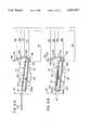
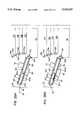
- FIG. 3is a schematic side elevational view of the deposit processing device shown in FIG. 1 showing one side of the device;
- FIG. 4is a schematic side elevational view of the deposit processing device shown in FIG. 1 showing the other side of the device;
- FIG. 5is a top, plan view of the deposit processing device shown in FIG. 1;
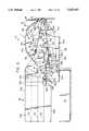
- FIG. 6is an enlarged, partially broken away side elevational view of the deposit processing module and a portion of the deposit storage module showing the deposit processing module oriented to a top storage bin position;
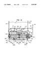
- FIG. 7is a side elevational view of the deposit processing module and deposit storage module showing an opposite view of that shown in FIG. 6;
- FIG. 8is a top, plan view of the deposit processing module when positioned as shown in FIG. 7;
- FIG. 9is a longitudinal sectional view taken along line 9--9 of FIG. 8;
- FIG. 10is a plan view taken along line 10--10 of FIG. 9 showing portions of an upper transport
- FIG. 11is a plan view taken along line 11--11 of FIG. 9 showing portions of a lower transport
- FIG. 12is a sectional view taken along line 12--12 of FIG. 9;
- FIG. 13is a sectional view taken along line 13--13 of FIG. 9;
- FIG. 14is an end view taken along line 14--14 of FIG. 9;
- FIG. 15is an enlarged view showing the gate mechanism
- FIG. 16is a fragmentary, further enlarged view of FIG. 9 showing the gate mechanism in a first position
- FIG. 17is an enlarged view showing the gate mechanism in a position for conveying a document between the upper transport and the lower transport;
- FIG. 18is a view similar to FIG. 16 showing the document processing module in a gate full "up" position from which a single document may be sent to a select location or be received therefrom;
- FIG. 19is an end elevational view taken along line 19--19 of FIG. 18;
- FIG. 20is a schematic, perspective view showing motor drive arrangement for moving components of the document processing module.
- FIGS. 21A-21Care schematic views of the deposit processing device shown in FIG. 1 illustrating successive positions of the deposit processing module when an envelope deposit is processed;
- FIGS. 22A-22Fare schematic views of the deposit processing device shown in FIG. 1 illustrating successive positions of the deposit processing module when a single document deposit process;
- FIGS. 23A-23Dare schematic views of the deposit processing device as shown in FIG. 1, showing the successive positions of the deposit processing module when duplexing (i.e., inverting) a single document deposit;
- FIG. 24is a perspective view of the deposit processing module showing the module opened for service
- FIG. 25is a block diagrammic representation of the electronic control system for the document processing device shown.
- FIG. 26is a side elevational, sectional view of the receiving end of a document processing module according to the present invention, illustrating a modification to the document processing module to enable it to receive and process rigid or semi-rigid cards;
- FIG. 27is a view taken along lines 27--27 of FIG. 26;
- FIGS. 28A and 28Bare schematic views of the deposit processing module as shown in FIGS. 26 and 27, showing several positions of the deposit processing module when receiving a rigid or semi-rigid card;
- FIGS. 29A and 29Bare schematic views of a deposit processing module according to the present invention, together with an automatic document feeder for use therewith.
- Apparatus 10is adapted to receive deposits such as envelopes containing currency or the like, and single document deposits, such as checks, utility bills, or other single sheet documents.
- depositshall generally refer to both envelopes and single sheet documents, the specific type of deposit being identified later in the specification when necessary to explain the operation of apparatus 10.
- Apparatus 10is preferably for use in conjunction with a conventional automatic teller machine (ATM), wherein access to the ATM is by means of a conventional magnetic identification card.
- ATMautomatic teller machine
- apparatus 10has other uses and applications and may find advantageous application in situations not involving ATMS or ATMS requiring credit card access.
- Apparatus 10would typically be situated adjacent a housing facia 22 within a housing (not shown).
- Housing facia 22includes a plate 24 having a deposit entry slot 26 which is accessible to a customer formed therein.
- apparatus 10is shown resting upon a support surface 28 which is schematically illustrated.
- An envelope storage bin 30is positioned to one side and below apparatus 10 to receive and store envelope deposits which have been processed therethrough.
- Apparatus 10is primarily comprised of a deposit processing module 12, and a deposit storage module 14 which is attachable thereto.
- deposit processing module 12is adapted to receive deposits through deposit receiving slot 26 and after processing same, to discharge the deposits into deposit storage module 14 or the envelope storage bin 30.
- the end of deposit processing module 12 adjacent the housing faciashall be referred to as “the receiving end” or “front end” of the module, and the portion of the module adjacent deposit storage module 14 shall be referred to as the “discharge end” or “back end” of the module.
- Apparatus 10is positioned so that the receiving end thereof is adjacent deposit entry slot 26.
- deposit processing module 12is generally comprised of three (3) sections or components, each of which is pivotally attached at one end to permit separation from each other for servicing as will be described in greater detail below. More specifically, deposit processing module 12 is generally comprised of an upper module section 100, a lower module section 200, and a transport and gate assembly 300 which is positioned therebetween.
- upper module 100is generally comprised of a support housing 102 having two spaced-apart, parallel sidewalls 104, 106.
- a spacer bar 108 and a cover plate 110extend between sidewalls 104, 106.
- Sidewalls 104, 106are formed to provide mounting surfaces for a transport motor 40, a pivot motor 50, and a shuttle motor 60.
- Transport motor 40 and pivot motor 50are mounted to sidewall 104 with their respective drive shafts extending therethrough.
- Shuttle motor 60is mounted on an inward extending panel 112 cut from sidewall 106.
- a printed circuit board 114Adjacent to motors 40, 50 and 60, a printed circuit board 114 is provided and mounted on inward extending tabs (not shown) formed in the sidewalls 104, 106.
- a smaller printed circuit board 116is provided at the discharge end of upper module section 100.
- Printed circuit board 114, 116each include end portions which project beyond in sidewall 104, as best seen in FIGS. 1 and 2.
- Cover 110(best illustrated in FIG. 9) is mounted to the sidewalls 104, 106 to enclose motors 40, 50, 60 and printed circuit board 114.
- the lower end 118 of cover plate 110 adjacent the receiving end of deposit processing module 12is inturned toward the center thereof, as best seen in FIG. 9.
- Floating plate 120is generally U-shaped (as best seen in FIG. 13) and is dimensioned to be received between sidewalls 104, 106 of housing 102 of upper module section 100.
- floating plate 120is formed of a single metal sheet having the ends and sides bent to a desired configuration.
- several components comprising the present inventionprimarily the structural housings and support members, are preferably formed from single metal plates into complex shapes by cutting and bending such plates by conventionally known forming techniques. It is believed that the forming of such components is within the ability of those skilled in the art of metal forming and that the shapes of the components and how they may be formed is discernible from the drawings of the present invention.
- a transverse slot 122is formed in floating plate 120 to receive a printer shuttle 70.
- portions of floating plate 120 along the sides of slot 122are bent upward to define rails 124 which act as guides and mounting surfaces for printer shuttle 70.
- An auxiliary mounting bracket 126shown in FIG. 9, is attached to the upper surface of floating plate 120 to provide an additional guide surface for primer shuttle 70 and to confine printer shuttle 70 within the slot 122.
- the upper end of the auxiliary mounting bracketdefines a generally L-shaped rail 126a along which printer shuttle may slide.
- the receiving end of the floating plate 120i.e. the end of the floating plate adjacent the deposit receiving slot 26, has an upturned leading edge 128 which is formed to mesh with the inturned lower end 118 of cover plate 110.
- a centrally located, non-continuous rail 130extends along the length of floating plate 120.
- Rail 130is generally comprised of two (2) rail sections 132, 134 which are disposed on either side of slot 122. Rail sections 132, 134 project downward from the lower surface of floating plate 120, and are dimensioned to extend slightly below the lower surface of printer shuttle 70.
- the receiving end of rail 130is upturned and dimensioned to extend into slots (not shown) in the inturned end 118 of cover plate 110.
- An idle guide roller 136extends through a slot (not shown) in the leading edge of rail section 132.
- Guide roller 136is mounted on a roller strut 138, shown in FIG. 12, which is mounted to rail section 132 and is pivotable relative thereto.
- Rail section 134 at the discharge end of floating plate 120is best shown.
- Rail section 134is comprised of a first portion 134a which is fixedly secured to floating plate 120 and a second portion 134b which is formed to be slidably received by portion 134a.
- Rail portion 134bis attached to a flexible deflector 150 which is provided at the discharge end of floating plate 120.
- Deflector 150is preferably of a molded plastic construction and is shaped to be positioned on the upper surface of floating plate 120 and extend downward over the end thereof.
- a flat coiled leaf spring 152 secured to floating plate 120biases the overextending end of deflector 150 downward to the position shown in FIG. 9.
- a rectangular pin 154extends laterally outward from each side of deflector through rectangular slots 156 formed in sidewalls 104, 106 of housing 102, as shown in FIGS. 2 and 6.
- deflector 150is movable within support housing 102 on rectangular pins 154 sliding in slots 156 of sidewalls 104, 106.
- deflector 150is attached to rail portion 134b such that the free end of floating plate 120 is confined therebetween and slidable relative thereto.
- the discharge end of floating plate 120is reciprocally movable, to a limited extent, toward deposit storage module 14, i.e. to the right in FIG. 9, in addition to being movable in a vertical direction (i.e. by movement of rectangular pins 154 in slots 156).
- the receiving end of floating plate 120is likewise movable relative to housing 102.
- the receiving end of floating plate 120is mounted to housing 102 by means of pins 162 projecting outward from the sides thereof which pins 162 extend through inclined slots 164 in sidewalls 104, 106 of housing 102, as best seen in FIG. 7.
- Pins 162which extend through sidewalls 104, 106 are attached by a helical spring 166 to pins 168 which are fixedly mounted to the outer surfaces of sidewalls 104, 106.
- a pin 172extends from the side of floating plate 120 past sidewall 104 and is connected by helical spring 174 to a pin 176 extending from sidewall 104, as best seen in FIG. 6.
- Springs 166, 176bias floating plate 120 downward to a normal position, as generally shown in FIG. 9.
- printer shuttle 70a conventionally known print head is mounted within printer shuttle 70 for marking deposits with transaction code and/or customer information.
- Printer shuttle 70is formed to include a plurality of aligned slots to operatively receive rails 124, 126a.
- printer shuttle 70is adapted to be freely movable along rails 124, 126a.
- the upper part of printer shuttle 70includes an outward extending cam surface 72 which is positioned to engage a pin 74 mounted to a plate on housing 102. Pin 74 engages cam surface 72 when printer shuttle 70 is in a predetermined position within slot 122.
- cam surface 72 and pin 74are dimensioned to cause the printer shuttle 70 and floating plate 120 to move upward relative to the lower module section 200 and transport and gate assembly 300 of the document processing module 12 as will be described in greater detail below during the discussion of the operation of the present invention.
- Lower module section 200includes a generally U-shaped housing 202 comprised of a flat plate 204 and two (2) downward extending sidewalls 206, 208.
- a pair of flanges 212, 214which are in planar alignment with sidewalls 206, 208, extend upward from the plate 204.
- flanges 212, 214are notched out from plate 204 and result in voids 216 being formed therein.
- Each flange 212, 214includes an outward extending hub 218 which is in axial alignment with the other.
- the receiving end of plate 204is formed into a triangular shape, best seen in FIG.
- Guide portion 224 of the plate 204includes serrated edges to mesh with other module components (best seen in FIG. 10) as will be discussed later.
- the discharge end of the plate 204is also serrated (as best seen in FIG. 11) and formed to operatively interact with other module components.
- Two (2) generally parallel transfer slots 232, 234, best seen in FIG. 11,are formed into plate 204 and extend transverse to the longitudinal axis thereof. Slot 232 is dimensioned to a portion of a scanning imager 80. Scanning imager 80 is disposed below the plate 204 and between the sidewalls thereof with a scanning window 82 extending into the slot 232 and being flush with the upper surface of the plate 204.
- Slot 234is provided to receive a magnetic ink character recognition (MICR) shuttle 90.
- MICRmagnetic ink character recognition
- portions of the plate 204 defining slot 234are formed as spaced-apart rails 236 on which MICR shuttle 90 is mounted and can slide. Rails 236 are dimensioned such that the MICR shuttle 90 is flush with the upper surface of the plate 204. As best seen in FIG. 11, rails 236 are formed to extend beyond the sidewall 206 of the housing 202 to enable the MICR shuttle 90 to move sufficiently towards sidewall 206 such that the operative components of the MICR can magnetically charge or read information from a deposit position to that side of the plate.
- MICRmagnetic ink character recognition
- MICR shuttle 90is comprised of a housing having slots dimensioned to receive the rails 236.
- the operative portion of the MICR headis designated 240 in the drawings.
- Adjacent the MICR head on MICR shuttle 90a sensor 242 is provided.
- sensor 242is a retro-reflective sensor which is capable of detecting objects (i.e. sheet documents) passing thereover.
- a solenoid 250is mounted below plate 204.
- Solenoid 250includes a reciprocally movable pin 252 and a sensor 254 (shown schematically in FIG. 25) to monitor movement of pin 252.
- Primed circuit boards 264, 266, which will be described in greater detail below,are mounted below plate 204 adjacent the distal ends thereof as seen in the drawings.
- the transport and gate assembly 300is generally comprised of an elongated, hollow, box-like platen 310 and a gate 410 which is pivotably mounted to the discharge end of platen 310.
- platen 310is formed from a generally U-shaped bottom member 312 and a flat top member 314 which are secured to each other (by means not shown) to form a structure having a rectangular, box-like cross-Section as best seen in FIG. 13.
- the distal ends of platen 310are serrated to operatively mesh with the components located adjacent the ends thereof.
- the receiving end of platen 310meshes with the serrations formed on guide portion 224 of plate 204, as shown in FIG. 10 and the discharge end of the platen 310 meshes with serrations formed on gate 410, which is best seen in FIG. 10.
- a drive shaft 320extends through the receiving end of the platen 310.
- shaft 320extends through bushings 322 mounted through the sides of the U-shaped bottom member 312 so as to enable platen 310 to be freely pivotally movable on drive shaft 320.
- Drive shaft 320extends beyond the sides of platen 310 and includes a pair of outer bushings 324 which extend through the sidewalls 104, 106, 206, 208 of housing 102 of the upper module section 100 and the housing 202 of the lower module section 200.
- the upper module section 100 and the lower module section 200 and the platen 310are all pivotally mounted onto drive shaft 320, with the drive shaft 320 being freely rotatable relative to each.
- a tooth drive gear 332is fixedly secured.
- a second tooth gear 334is fixedly mounted near the middle of drive shaft 320.
- Gear 334extends through slots formed in the upper and the lower surfaces of platen 310.
- a second shaft 336is provided, as shown in FIG. 14.
- Shaft 336extends through bushings 338 in the sides of U-shaped member 312 to facilitate free rotation of shaft 336 relative to platen 310.
- a tooth gear 342is fixedly mounted to shaft 336 near the middle thereof to be in alignment with gear 334 on drive shaft 320.
- a pair of conical rollers 344are mounted on shaft 336 for rotation therewith and are positioned on opposite sides of gear 342.
- a pair of gears 352, 354are mounted on one end of shaft 336.
- a timing belt 356connects gear 352 to a gear 358 on a shaft 362 which extends through platen 310.
- Shaft 362 and roller 364are positioned to be above the track of MICR shuttle 90.
- Roller 364extends slightly below the lower surface of platen 310 through a slot formed therein.
- a rail 368which is aligned with and extends between the gears 334, 342 on the drive shaft 320 and shaft 336, projects from the upper surface of platen 310.
- Rail 368is provided to support a continuous transport belt 370 which encircles platen 310 lengthwise.
- transport belt 370is mounted on gears 334, 342 of shafts 320, 336 respectively.
- Transport belt 370has a first belt run 370a across rail 368 on the upper surface of platen 310 and a second belt run 370b along the lower surface of platen 310.
- shaft 336 and roller 364are positioned within platen 310 such that a gap 380 is formed between belt run 370b and the upper surface of plate 204, as best seen in FIGS. 15 and 16.
- Gap 380extends generally from the discharge end 18 of platen 310 to under MICR shuttle 90. Beyond MICR shuttle 90 to the receiving end 16 of platen 310, belt run 370b generally engages the upper surface of plate 204.
- Gate 410includes a barrier portion 412 which extends across the front of platen 310, as shown in FIG. 10, and a pair of flat arms 414 which extend along the sides of the platen 310. Arms 414 are pivotally mounted to platen 310 on pins for pivotable rotation relative thereto. In the embodiment shown, arms 414 are generally J-shaped and are secured to barrier portion 412 by fasteners (not shown). Arms 414 project upward above the upper surface 310 of the platen and are joined to barrier portion 412 such that arms 414 extend thereabove.
- a tempered metal rod 416extends from the sides of platen 310 up over the upper surface of barrier portion 412 and acts as a spring to bias gate 410 in a downward direction.
- arms 414are formed to include a lower edge 422, shown in FIG. 16, which acts as a stop against shaft 336 to limit gate 410 in its downward direction to neutral position as shown in FIG. 16.
- Arms 414likewise include a second surface 424 which limits the upward movement of gate 410 through engagement with shaft 336, as shown in FIG. 18.
- Barrier portion 412has a generally flat upper surface 426 and is dimensioned such that upper surface 426 is aligned with the upper surface of platen 310 when the gate 410 is in the neutral (home) position. As best seen in FIG.
- the ends of upper surface 426are serrated to mesh with the edges of platen 310 and portions of deposit storage module 14.
- notchesare formed in gate 410 to enable it to move without contacting the conical rollers 344 or transport belt 370, as shown in the drawings.
- an upper discharge slot 430is defined between the upper surface 425 of the gate 410 and the lower surface of deflector 150.
- barrier portion 412includes an arcuate inner surface 432 facing and encompassing the end of platen 310. Arcuate surfaces 432 merges with a fiat lower surface 434.
- a generally fiat plate 436is provided below barrier portion 412.
- flat plate 436is formed as part of arms 414. Plate 436 is spaced from lower surface 434 of barrier portion 412 and defines a lower discharge slot 440 therewith.
- the ends of lower surface 434 and of plate 436are likewise serrated to mesh with the ends of platen 310 as well as components on deposit storage module 14.
- a curved, outward facing surface 442is formed on the sidearm. Surface 442 faces towards the deposit storage module 14 and is recessed slightly below the outer facing surface of barrier portion 412.
- An inclined abutment surface 444is formed at the upper portion of barrier portion 412 and merges with curved surface 442.
- upper module section 100, lower module section 200, and the transport and gate assembly 300which have heretofore been described separately, are pivotally mounted to drive shaft 320, which is best seen in FIG. 24.
- Upper module section 100, the lower module section 200, and the transport and gate assembly 300are adapted to be joined together in operative engagement with each other.
- pairs of latch elements 452, 454are mounted on each side of housing 102 of the upper module section 100 to lock onto tabs 456 extending outward from the sides of the housing 202 of the lower module section 200.
- a release bar 458spans sidewalls 104, 106 of housing 102 of upper module section 100 to connect the latch elements 452 on each side thereof.
- upper module section 100 and platen 310define a first transport therebetween
- lower section 200 and platen 310define a second transport therebetween, which is best seen in FIG. 9.
- a first transportis defined between floating plate 120 and the upper surface of the platen 310.
- transport belt 370is operatively disposed against rail 130 on floating plate 120 (i.e. envelopes and deposits) to capture documents therebetween and to transport the deposits along rail section 132, 134 on floating plate 120 between the receiving end and the discharge end of document processing module 12.
- the second transportis defined by the lower surface of platen 310 and plate 204 of housing 202 of the lower module section 200.
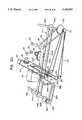
- document processing module 12is pivotally mounted to a support frame 500, best seen in FIGS. 4, 6, 7 as 13.
- support frame 500is generally U-shaped and includes a bottom wall 502 and two (2) sidewalls 504, 506 which are generally parallel to each other and spaced apart to receive the document processing module 12 therebetween.
- Document processing module 12is pivotally mounted to support frame 500 by means of pins 512 extending through sidewalls 504, 506 into hubs 218 on housing 202 of bottom module section 200.
- a major portion of sidewall 504is cut away to permit components of document processing module 12, such as the end shafts 336, 362 to extend therethrough, which is best seen in FIG. 2.
- FIG. 2As shown in FIG.
- a gear block 522 having an arcuate rack gear 524 formed along the upper edge thereofis mounted to sidewall 504.
- Rack gear 524is positioned to operatively engage a pinion gear 52 on the shaft of pivot motor 50.
- Adjacent gear block 522, sidewall 504is formed to have a curved edge 532 having a plurality of notches and windows 534 formed therethrough.
- Sidewall 506 of the U-shaped support frame 500includes a plurality of apertures, designated 550a, 550b, 550c, 550d, 550e, 550f, and 550g which are arranged in an arcuate pattern, as best seen in FIG. 7.
- Apertures 550a, 550b, 550c, 550d, 550e, 550f and 550gare positioned to receive pin 252 of solenoid 250 so as to lock deposit processing module 12 in one of a plurality of specific positions relative to deposit storage module 14, as will be described in greater detail below.
- Sidewalls 504, 506each include locating notches 562 which are provided to locate and attach document storage module 14 to the document processing module 12.
- each motoris preferably a reversible stepping motor wherein the relative rotational position of it may be monitored, and thus the position of components driven thereby may be monitored.
- transport motor 40is mounted to sidewall 104 of upper module section 100 with its drive shaft extending therethrough.
- a gear 42is mounted to the shaft of transport motor 40 to drive a timing belt 44 which connects gear 42 to gear 332 on drive shaft 320.
- transport motor 40is operable to rotate drive shaft 320 which in turn rotates shaft 336 by means of transport belt 370.
- Shaft 336in turn drives shaft 362, and roller 364 thereon, by means of timing belt 356.
- transport belt 370, conical rollers 344 and roller 364are simultaneously driven in the same direction by transport motor 40.
- pivot motor 50is operable to drive pinion gear 52 across rack 524 on plate 522, which in turn is operable to cause deposit processing module 12 to pivot about axis A on pins 512 and to angularly orient deposit processing module 12 to one of the several positions 550a, 550b, 550c, 550d, 550e, 550f, 550g.
- Shuttle motor 60is provided to reciprocally move printer shuttle 70 and MICR shuttle 90 across the width of platen 310.
- a drum 62is mounted on the shaft of motor 60.
- the ends of a cable 64are mounted to drum 62 and wound around drum 62 to enable cable 64 to be wound or unwound in each direction depending upon the rotation of shuttle motor 60.
- cable 64is wrapped over a system of pulleys, designated 66 in the drawings.
- Pulleys 66are positioned to define form a continuous cable circuit, portions of which are adjacent, and run parallel to, the direction of movement of printer shuttle 70 and MICR shuttle 90.
- Idler pulleys 66are mounted to drive shaft 320 to direct the cable therearound.
- Printer shuttle 70 and MICR shuttle 90fixedly attached to cable 64 so as to move therewith.
- document processing module 12includes a plurality of printed circuit boards 114, 116, 264, 266. As best seen in FIG. 9, the printed circuit boards 114, 264 are disposed at the receiving end of document processing module 12, and circuit board 114 being above and circuit board 264 being below platen 310. Circuit board 264 includes a pair of light emitters, designated 264a, 264b in the drawings, as best shown in FIG. 11. As best shown in FIG.
- openings in plate 204, platen 310 and inturned portion of cover 110permit a light beam to be directed from emitters 264a, 264b through the upper and lower transports towards a pair of light receivers 114a, 114b on opposing printed circuit board 114.
- emitters 264a, 264b and receivers 114a, 114bare positioned to operatively align relative to each other, and each emitter and its respective receivers form an optical sensor.
- three (3) light emitters 266a, 266b, 266care provided on the lower circuit board 266 to direct individual beams of light through openings in plate 204, platen 310 and floating plate 120 toward light receivers 116a, 116b, 116c on the circuit board 116.
- emitters 264a, 264b, 266a, 266b and their respective receivers 114a, 114b, 116a, 116bare generally centrally disposed with respect to the center line of platen 310.
- Light emitter 266a and its related receiver 116a(not shown) is generally disposed along one edge of platen 310, as best seen in FIG. 11.
- a generally U-shaped module rotation sensor 182is provided to receive curved edge 532 of sidewall 504. Sensor 182 is operable to monitor the angular position of deposit processing module 12 by sensing the position of windows 534 with respect thereto.
- Conventionally known retro-reflective switchesshown schematically and designated 184 and 186 in FIG. 25, are also preferably provided to sense a home position for print shuttle 70 and for MICR shuttle 90, the home position being adjacent sidewall 104 of housing 102.
- a sensor 188is also preferably provided to sense a "gate up" position, i.e. when gate 410 is in its uppermost position.
- An additional sensor, designated 190 in FIG. 25,may also be provided to indicate when latch elements 452, 454 are properly secured to ensure proper alignment and mating of the upper and lower module sections 100, 200 and transport and gate assembly 300. Still further, a sensor, designated 192 in FIG. 25 is also preferably provided on print shuttle 70 to sense the edge of a deposit for the purpose of locating print shuttle 70 relative to the deposit when information is to be printed thereon.
- circuit boards 114, 116, 264, 266are connected to each other and to operatively engage components such as motors 40, 50, 60, printer shuttle 70, scanner imager 80 and MICR shuttle 90 by flex circuits (not shown) which can flex and bend as deposit processing module 12, and various components thereof, move and operate.
- flex circuitsnot shown which can flex and bend as deposit processing module 12, and various components thereof, move and operate.
- a portion of the circuit boards 114, 116extends beyond sidewall 104 of the document processing module 12, as best seen in FIG. 1.
- circuit boards 114, 116include circuit lead lines to be received within female connectors 34 on a master circuit board 36.
- Master circuit board 36is adapted to be mounted on spacer posts 38 extending outward from the document processing module 12, as best seen in FIG. 14, wherein the master circuit board 36 and a female connector 34 are shown in phantom.
- FIG. 25a block diagrammic representation of the internal control system for the document processing module 12 is shown.
- the physical operation of deposit processing module 12are basically controlled by a central processing unit 600 which is programmed to control operations of the various components of deposit processing module 12 by means of a program stored therein.
- Central processing unit 600is connected to light emitters and receivers, and to motors 40, 50, 60. Information received from stepping motors 40, 50, 60 and optical sensors enables central processing unit 600 to monitor the relative position of the components, as well as to identify and monitor deposits placed therein.
- Central processing unit 600is connected to the printer within printer shuttle 70 to provide instructions and information to be printed on a deposit.
- Scanner imager 80is connected to the control processing unit (CPU) of the ATM to receive information in coded form for present transmission to an external database, such as a bank or similar financial institution, or for display to the ATM user on the CRT of the ATM, or for storage within memory of the CPU of the ATM for transmission at a later time.
- Central processing unit 600is likewise connected to the MICR read head to receive information typically present on checks or other similar documents in coded text.
- a separate decoding processing unit 610is provided to decode and translate information obtained from a deposit to provide information identifiable to central processing unit 600 or to the external database.
- deposit storage module 14is a rectangular, box-like structure having two spaced-apart parallel sidewalls 702, 704, a top wall 706, and a bottom wall 708.
- a plurality of spaced-apart shelves 712extend between sidewalls 702, 704 to define compartments 714, 716, 718, 720.
- Sidewall 704, top wall 706 and bottom wall 708are formed so as to define an open comer for access to compartments 714, 716, 718, 720.
- a side panel 722is spaced-apart and mounted to sidewall 702.
- Mounting lugs 724extend from sidewall 704 and panel 722 and are positioned so as to be received within mounting notches 562 on support frame 500 of deposit processing module 12.
- mounting lugs 724are provided to position deposit storage module 14 adjacent to deposit processing module 12.
- latch elements 726, 728are provided to operatively lock and hold deposit storage module 14 in engagement with deposit processing module 12.
- compartments 714, 716 and 718are adapted to receive single document deposits from deposit processing module 12, as shown in FIGS. 16 and 17.
- a drive shaft 732having a plurality of drive rollers 734 thereon is provided.
- Each drive shaft 732extends between sidewalls 702, 704 and has one end which projects into the space defined between sidewall 702 and panel 722.
- a gear 736is mounted on the end of each drive shaft 732 and meshes with a second intermediate gear 738 which is also confined between panel 722 and sidewall 702.
- Gears 738 of each compartment 714, 716, 718are positioned to align and mesh with gear 354 on shaft 336 of platen 310.
- drive shaft 732 and drive rollers 734 at the entrance to compartments 714, 716, 718are driven by gear 354 on platen 310 when platen 310 is aligned with a specific compartment.
- Idle rollers 742 mounted on shafts 744are provided above and in mating engagement with drive rollers 734.
- Deflectors 746are provided between drive rollers 734 and idle rollers 742 to direct single document deposits into the associated compartment. The leading edges of the deflectors are serrated to mesh with the leading edges of platen 310.
- the lowermost compartment 720is provided to enable document processing module 12 to duplex, i.e. to invert, single document deposits.
- a pair of drive shafts 752are provided at the entrance to compartment 720.
- Each drive shaft 752includes drive rollers 754 which mate with rollers 754 on the opposite drive shaft 752.
- a drive gear 756is provided at the end of each shaft 752 and meshes with an intermediate gear 758 which is operable to engage gear 354 on shaft 336 of platen 310.
- a pair of similar gate actuators 760are mounted to the inner surfaces of sidewalls 702, 704.
- Gate actuators 760are mounted on a pair of pins 762, 764 which are received in slots formed in each actuator 760.
- a biasing spring 766having a predetermined spring force, urges actuators 760 upward to a neutral position as shown in FIG. 15.
- the upper slotis generally L-shaped, while the lower slot is straight.
- Each actuator 760is formed to have a pair of cam surfaces 772, 774 which are dimensioned to operatively engage and interact respectively with surfaces on gate 410 as will be described in greater detail below.
- the slots in gate actuator 760are configured such that when a downward force sufficient to overcome the biasing force of spring 766 is exerted on the inclined cam surface 772 of actuator 760, actuator 760 is forced downward and back (i.e. away from gate 410).
- one slotis inclined relative to the other slot to impart a slight rotation of actuator 760 as it moves downwards.
- the L-shaped slotallows actuator 760 to pivot backward about lower pin 764 when an upward force is exerted on lower cam surface 774, as will be described in greater detail below.
- apparatus 10is preferably integrated as part of an automatic teller machine (ATM), wherein access to apparatus 10 may be accomplished by using conventionally known magnetically coded cards and utilizing keypads typically provided on the ATM to establish the identity of a customer.
- Authorization to use apparatus 10may be obtained from a remote, external database, such as in a bank or other financial institution or from records maintained in memory within the central processing unit of the ATM.
- system and hardware for accessing apparatus 10 in and of itselfforms no part of the present invention.
- apparatus 10need not be part of an automatic teller machine (ATM), but may be used as a stand alone unit for other applications wherein access to the apparatus may be by means other than a magnetically encoded card.
- ATMautomatic teller machine
- deposit processing module 12is adapted to operate in conjunction with deposit storage module 14.
- specific operations of deposit processing module 12are accomplished through interactive engagement between the gate 410 of document processing module 12 and gate actuator 760 on deposit storage module 14.
- deposit processing module 12is pivotally movable about axis A to a plurality of positions relative to deposit storage module 14. In the embodiment shown, deposit processing module 12 is movable to seven (7) specifically defined positions relative to deposit storage module 14.
- each aperture 550a, 550b, 550c, 550d, 550e, 550f, 550g in support frame 500represents a specific position of deposit processing module 12.
- each aperture 550a, 550b, 550c, 550d, 550e, 550f, 550ghas been identified with respect to the function of deposit processing module 12 in such position.
- apertures 550a, 550b, and 550care positions for depositing single document deposits into compartments 714, 716, 718 of deposit storage module 14, aperture 550a also being a "home position" for deposit processing module 12.
- Aperture 550drepresents a single document deposit "aligning position” and a position wherein single document deposit is conveyed between the upper transport and the lower transport.
- Aperture 550erepresents a gate full “up” position and a position wherein single document deposits are conveyed from the lower transport to pinch rollers 754 and visa versa.
- Aperture 550frepresents a "facia-aligned position". This position also allows document deposits to be sent or received from pinch rollers 754 to the upper transport.
- Aperture 550grepresents an "envelope deposit position".
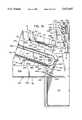
- FIG. 4generally shows deposit processing module 12 in the "facia-aligned position" for receiving a deposit, but also shows the range of movement of deposit processing module 12 by illustrating (in phantom) the positions of transport belt 370, (i.e. platen 310) would assume when document processing module 12 is in its extreme, uppermost and lowermost positions.
- envelope depositswhich may contain currency or other documents of value, or single document deposits, such as checks, utility bills, or other notes of value.
- envelope depositsare handled differently than single document deposits. Accordingly, hereinafter “envelope deposits” shall be referred to as such and designated “ED” in the drawings, and deposits such as a check, utility bills, or some other single note of value shall be referred to as a “single document deposit” and designated “DD” in the drawings.
- an authorization signal to allow access to apparatus 10is conveyed to central processing unit 600 from an external source.
- such signalmay be received from an automatic teller machine (ATM), a bank, or other financial institution or some other source.
- ATMautomatic teller machine
- central processing unit 600instructs pivot motor 50 to pivot deposit processing module 12 about axis "A" to move same to the facia-aligned position, a position illustrated in FIG. 4. More specifically, pivotal movement of deposit processing module 12 is accomplished by pinion gear 52 being driven over arcuate rack gear 524.
- the relative position of deposit processing module 12is monitored by central processing unit 600 based upon information received from stepping motor 50 and from information received from angular position sensor 182.
- central processing unit 600may determine the relative location of deposit processing module 12 relative to deposit receiving slot 26 in housing facia 22, as well as the relative position of deposit processing module 12 relative to deposit storage module 14.
- pivot motor 50is stopped and solenoid 250 is actuated such that pin 252 thereon extends through aperture 550f in support housing 500.
- deposit processing moduleis thus locked and aligned into a deposit receiving position, wherein the upper transport is aligned with deposit receiving slot 26 through housing facia 22.
- central processing unit 600initiates transport motor 40, to initiate movement of transport belt 370 in a direction to draw a deposit into the upper transport.
- deposit processing module 12is capable of identifying the type of deposit inserted therein, i.e. envelope deposit ED or single document deposit DD, by means of the optical sensors provided at the receiving end of deposit processing module 12.
- the leading end of the depositenters the upper transport, it passes between light emitters 264a, 264b and light receivers 114a, 114b.
- emitters 264a, 264b and receivers 114a, 114bare positioned and have operational characteristics wherein they are capable of providing to central processing unit 600 information as to the length, width and opacity (which provides an indication of thickness) of the inserted deposit, with which central processing unit 600 can identify whether the deposit is an envelope or single document based upon such information.
- transport motor 40proceeds to transport drive belt 370 to convey the envelope deposit ED to a position under printer shuttle 70.
- Envelope deposit EDis drawn along rail 130 of floating plate 120 through frictional engagement with transport belt 370.
- transport belt 370 and rail 130 on floating plate 120project above their respective surfaces, the upper transport has ample clearance on either side of transport belt 370 (i.e. between floating plate 120 and platen 310) to facilitate the passage of envelope deposits ED which have lumps or enlargements to one side of drive belt 370.
- upper plate 120effectively "floats" relative to housing 102 of upper module section 100, and may move away from transport belt 370, the upper transport can accommodate the passage of relatively thick envelope deposits ED.
- floating plate 120not only moves upward away from transport belt 370 to receive thick deposits, it also shifts in the direction of movement of the thick deposit.
- slots 164, through which pegs 162 extend,are slanted to allow floating plate 120 to shift upward and in the direction of movement of the deposit. Such movement is facilitated because the dispensing end of floating plate 120 may slide between deflector 150 and rail section 134a.
- Central processing unit 600is programmed to position the envelope deposit below printer shuttle 70 by controlling transport motor 40. Positioning envelope deposit ED below printer shuttle 70 can be accomplished by using the optical sensors, i.e. light emitters 266a, 266b, 266c and light receivers 116a, 116b and 116c to establish when the leading edge of the envelope deposit has reached the discharge end of deposit processing module 12. With the envelope deposit ED positioned below printer shuttle 70, central processing unit 600 may activate shuttle motor 60 to position print head 70 to a desired location relative to the envelope deposit ED. Shuttle motor 60 is operable to move printer shuttle 70 transverse to the path of envelope deposit ED by wrapping cable 64 onto drum 62. At this point, it should be noted that operation of shuttle motor 60 also moves MICR shuttle 90 along its respective track. In this respect, printer shuttle 70 and MICR shuttle 90 move in tandem across platen 310. A proximity sensor (not shown) adjacent one side of deposit processing module 12 is used to establish a "home position" for both printer shuttle 70 and MICR shuttle 90.
- a proximity sensor(not
- the central processing unit 600activates pivot motor 50 to rotate deposit processing module 12 to the lowest position, i.e. the envelope deposit position as schematically illustrated in FIG. 21C.
- gate member 410In this position, gate member 410 is in its neutral, lowermost position wherein the upper discharge slot 430 of gate 410 is aligned with the first transport.
- Transport motor 40is then actuated to drive the envelope deposit ED into envelope storage bin 30 for later retrieval by a bank employee or otherwise authorized individuals who can verify the content of the envelope deposit against the information entered by the user by retrieving the transaction information from memory of central processing unit 600.
- Informationis printed onto envelope deposit ED by passing envelope deposit ED beneath printer shuttle 70 (by means of transport belt 370) and simultaneously activating the print head within printer shuttle 70.
- the information printed onto envelope deposit EDwould typically include a transaction number, the date and/or other coded information relating to the transaction and/or customer. As will be appreciated, the information printed on the envelope deposit ED is likewise maintained in memory or transferred to an external database for later retrieval.
- FIGS. 22A-22Fthe processing of a single document deposit is illustrated.
- a single document depositsuch as a check or utility bill is inserted into the deposit receiving slot, it is drawn into the upper transport (the document processing module being in the facia aligned position) and conveyed toward the printer head.
- the depositAs the document deposit DD passes between light emitters 264a, 264b and receivers 114a, 114b at the receiving end of the transport, the deposit is identified as a single document by means of the optical sensors which, as indicated above, scan the deposit as to its thickness, i.e., its opacity.
- the document depositwhen necessary, is "justified” or "aligned", i.e. moved toward the edge of platen 310 near sidewall 104 of housing 102.
- "justification" or “alignment” of the document deposit DDis accomplished by first identifying the amount and direction of misalignment of document deposit DD. This is accomplished utilizing light emitters 266a, 266b and 266c and receivers 116a, 116b and 116c. In this respect, if document deposit DD is misaligned, the leading edge of document deposit DD will be conveyed by transport belt 370 past each corresponding pair of light emitters 266a, 266b and 266c and receivers 116a, 116b and 116c at a different time.
- central processing unit 600By sensing when the sequence and time when each light beam is broken, and knowing the speed the document deposit is being conveyed along the transport path by belt 370, central processing unit 600, by processing a trigonometric calculation can determine the amount and direction of misalignment of document deposit DD. Specifically, it can determine whether the leading edge of document deposit DD is away from side wall 104 (i.e. with the trailing edge being near side wall 104) or whether the trailing edge of document deposit DD is angled away from side wall 104. Once the position of the document is established, "justification" or “alignment” of the document is generally accomplished by repeatedly transporting the misaligned end of document deposit DD, i.e. the end of the document outermost or furthest from side wall 104 over conical rollers 344, shown in FIG. 10, between the upper and lower transport.
- document processing module 12is moved to its "aligning position", best seen in FIG. 17 and schematically illustrated in FIG. 22C.
- cam surface 772 of gate actuator 760engages abutting surface 444 of gate 410 and forces gate 410 upward into a position wherein arcuate deflecting surface 432 of gate 410 is aligned with the upper surface of transport belt 370.
- biasing spring 766 on actuator 760has sufficient spring force to counteract the biasing effect of tempered rods 416 which bias gate 410 to a downward position.
- Shuttle motor 60is actuated to move printer shuttle 70 (together with the MICR shuttle 90) to a position where cam surface 72 on shuttle housing 70 rides up onto pin 74 extending from support housing 102 to lift floating plate 120 away from the single document deposit.
- Plate 120is lifted away from belt 370 to reduce the friction drive exerted by belt 370 on document deposit DD.
- a "high frictional drive” conditionexists between the deposits and transport belt 370 to drive deposits along the first transport.
- a "low frictional drive” conditionexists between transport belt 370 and the deposit.
- a "low frictional drive”is required to enable conical rollers 344 to shift a document deposit DD toward side wall 104.
- conical rollersare designed to exert a relatively small lateral force, in the order of 1 ounce, on document deposit DD.
- document deposit DDis conveyed by transport belt 370 to a position where the leading edge thereof is over conical roller 344.
- Transport motor 40is then repeatedly driven, first in a forward direction and then in a reverse direction, to repeatedly convey the leading edge of single document deposit DD over conical rollers 344.
- Arcuate surface 432 of gate 410causes the leading edge to be guided around the end of platen 310 between the respective transports.
- the tapered surfaces of such rollers 344causes the leading edge of the document deposit DD to shift towards one side of platen 310.
- the optical sensorcomprised of light emitter 266a and light receiver 116a which are positioned along the edge of platen 310, as best seen in FIG. 14, indicate when the single document deposit DD is aligned along the edge of platen 310.
- the document depositis considered “aligned” or “registered” along the edge of the platen when eighty percent (80%) of the deposit is determined to be along the edge of platen 310.
- the inner surface of side arm 414 of gate 410acts as a step and prevents the edge of the document deposit from shifting past the edge of platen 310.
- gap 380creates a "low friction drive" condition such that when the trailing edge of document deposit DD is repeatedly driven over conical rollers 344, the trailing edge is forced into alignment by conical rollers 344 in a manner as described above.
- leading edge of the document deposit DDwhich is captured between MICR shuttle 90 and transport belt 370, experiences a "high frictional drive” condition which generally maintains the leading end of the document deposit in its original position as the trailing edge is conveyed into alignment by conical roller 344.
- the relative position of the document deposit during alignmentis monitored by means of the optical sensors, i.e. emitters 266a, 266b, 266c and receivers 116a, 116b, 116c, provided along the discharge end of the transports together with the sensor 242 mounted to the MICR shuttle 90.
- the optical sensorsi.e. emitters 266a, 266b, 266c and receivers 116a, 116b, 116c, provided along the discharge end of the transports together with the sensor 242 mounted to the MICR shuttle 90.
- documents such as checks or utility billstypically include information set forth thereon in an ANSI standard bar code, wherein the bar code is printed with a magnetizable ink.
- Information typically found on commercial checks or utility billswould include: (1) institutional information regarding the institution issuing the check or bill, (2) an account number, and (3) a check number, bill number or statement number relating to the particular document. Larger institutions may also include (4) the amount of the check or bill, as part of the bar code information.
- MICR headAs the document deposit passes over the MICR head, it also passes over window 82 of scanner imager 80. As it does so, an image of the downward facing side of the document deposit is obtained and conveyed to central processing unit of the ATM via the scanner card for storage in memory, or is immediately transferred to external memory at the bank or financial institution. In this respect, transport belt 370 conveys the entire document deposit over image scanner 80.
- transport drive motor 40is reversed to convey the document deposit back over the MICR head so that the above-identified magnetized, coded information may be removed therefrom.
- the coded informationis typically provided at specific locations on a certain type of document.
- Central processing unit 600is programmed to position the MICR shuttle 90 initially to a location wherein the coded information would be expected on the document deposit. In the event that the coded information is not found where expected, central processing unit 600 causes transport belt 370 to continually reverse itself to pass the document over the MICR shuttle 90, while at the same time, causing shuttle motor 60 to relocate MICR shuttle 90 along its rails to a position wherein the coded information might be found.
- central processing unit 600is programmed to reposition the MICR head to search the document for the coded information.
- informationmay be immediately transferred to the external memory of the financial institution, stored in memory by the central processing unit of the ATM to be downloaded to an external central database at a later time, or utilized in an immediate transaction with a customer.
- the document depositis transported by transport belt 370 back to the upper transport as illustrated in FIG. 22E, again using arcuate surface 432 of gate 410 as a guide.
- transaction informationis printed thereon as it passes beneath print shuttle 70.
- central processing unit 600would select one of the three compartments 714, 716, 718 of deposit storage module 12 into which document deposit DD is to be conveyed.
- pivot motor 50is actuated to cause document processing module 12 to be pivoted into alignment with the desired compartment.
- document processing module 12moves from its "deposit aligning position, as shown in FIGS. 17 and 22E, toward one of the three (3) compartments 714, 716, 718, as shown in FIG. 22F (wherein the upper transport is aligned with compartment 716) and FIG. 16 (wherein the upper transport is aligned with compartment 714), gate 410 moves past gate actuator 760.
- the upper end of gate actuator 760merely pivots about pin 764 out of the way of the lower portion of gate 410 as it moves thereby.
- gate actuator 760gate 410 is permitted to return to its normal (down) position wherein the upper .discharge slot 430 of gate 410 is in alignment with the upper transport.
- FIG. 16the relative positions of platen 310 and gate 410 of document processing module 12 when in alignment with compartment 714 of deposit storage module 14 are shown.
- the upper transportis in alignment with compartment 714 such that a document deposit conveyed from the upper transport would be directed between the drive rollers 734 and idle rollers 742.
- intermediate gear 738which meshes with gear 736 on drive shaft 732 operatively engages gear 354 on the end of shaft 336 on platen 310.
- gear 738in turn drives rollers 734.
- FIG. 22Fschematically illustrates a document deposit being driven into compartment 716.
- transport belt 370is driven to convey the document deposit toward the deposit storage module 14 wherein drive roller 734 at the entrance to the compartment with idle rollers 742 catch the leading edge of the document deposit and pull the document deposit into the compartment.
- apparatus 10includes means for "duplexing" or inverting a document deposit therein. Such feature is particularly applicable when a document deposit has been placed into document processing module 12 in an improper orientation, or merely to reorient a document deposit so as to enable both sides of the document deposit to be scanned or imaged by the MICR shuttle 90 or by the image scanner 80.
- FIGS. 23A-23Dillustrate a procedure for "duplexing" a document within document processing module 12.
- originally a document depositwould typically be processed discussed above.
- the document depositwould first be "aligned” in a manner as previously described. It would then be conveyed from the upper transport (as shown in FIG.
- central processing unit 600would initiate pivot drive motor 50 to move document processing module 12 from its aligning position as shown in FIG. 17 to its "duplex position" as shown in FIG. 18.
- surface 772 of gate actuator 760has caused gate 410 to move to its uppermost position.
- spring 766which is attached to gate actuator 760 has a spring force greater than the biasing force exerted by spring rods 416 on gate member 410, and therefore moves gate 410 upward wherein lower discharge slot 440 (i.e. the slot defined by lower surface 434 of gate 410 and lower plate member 436) of gate member 410 is in alignment with compartment 720.
- central processing unit 600causes pivot motor 50 to move document processing module 12 from its "duplex position" to the "facia-aligned position", as illustrated in FIG. 9, wherein the upper transport is essentially aligned with lower compartment 720.
- document processing module 12is moved from its "duplex position” to the "facia-aligned position”
- gate actuator 760is forced backward by abutting surface 444 of gate member 410.
- spring 766which biases gate actuator 760 does not have sufficient strength to resist the overall movement of document processing module 12. Accordingly, as described above, gate actuator 760 moves downward and shifts to the rear to enable gate 410 to move thereby when document processing module 12 moves to a lower position, i.e.
- document processing module 12is oriented such that drive gear 354 on shaft 336 through platen 310 is in operative engagement with intermediate gear 758 connected to the lower set of drive rollers 754.
- transport motor 40is actuated to cause the document deposit to be conveyed from lower compartment 720 into the upper transport, as schematically illustrated in FIG. 23D.
- Central processing unit 600instructs the document processing module 12 to return to the "aligning position" wherein the document deposit may be transported from the upper transport to the lower transport in a manner as previously discussed.
- the side of the document which was originally facing away from image/scanner 80 and MICR shuttle 90is now facing image/scanner 80 and MICR shuttle 90. In this position, it may be magnetically charged and read, or imaged in a manner as previously discussed.
- the document depositis then conveyed to one of the storage compartments 714, 716, 718, as discussed above.
- the inventionas heretofore described, thus provides a single document processing apparatus capable of receiving envelope deposits, as well as document deposits such as checks, utility bills, or other valued notes. More importantly, an apparatus according to the present invention can scan, image and print onto one or both sides of a document deposit and accomplishes such scanning, imaging and printing, utilizing only one magnetic read head, one image/scanner and one print head. In this respect, the ability to duplex a document deposit reduces the necessity of duplicate components.
- the use of a bi-directional transport as well as a movable MICR head and print headenables the present invention to read account code information off documents inserted to the document processing module in any orientation.
- the movable shuttles, particularly the MICR shuttle 90enable variable print locations on deposited documents to be located and scanned.
- the use of conical shaped rollers and a bi-directional transportenables justification and straightening of documents against the registration edge for searching the location of coded information on deposits. Still further, by justifying the document around a curved path (i.e. between the upper transport and the lower transport) document rigidity is ensured to provide better transport and alignment of all types of sheet material.
- a document processing module 12is also capable of processing rigid or semi-rigid cards such as a laminated driver's license or a plastic identification card.
- the receiving end of document processing module 12may be modified to include a rectangular slot 802, as seen in FIGS. 26 and 27. Slot 802 is formed in barrier portion 222 of plate 204 and is positioned to be in registry with the second transport, which is defined by plate 204 and the lower surface of platen 310.
- document processing module 12is shown in its "envelope deposit position.” In this position, slot 802 is in registry with deposit entry slot 26 in housing facia 22.
- a rigid or semi-rigid cardwhich is designated CD in the drawings, may be inserted into the second transport through slots 26 and 802.
- Card CDis captured between transport belt 370 and plate 204, and may be conveyed by transport belt 370 over scanner/imager 80, where an image of the card CD may be obtained.
- document processing module 12may be used to copy and store identification information or authorization information from a rigid or semi-rigid card CD.
- card CDUpon completion of the imaging, card CD would be returned to the user by reversing drive belt 370.
- card CDcould include magnetic information in coded form which could be read by the MICR head. Still further, according to the present invention, card CD may be transferred from the second transport to the upper transport to print thereon, in a manner similar to that described above to transfer sheet document during the duplexing procedure.
- document processing module 12would be moved to its "duplex position", as shown in FIG. 18.
- Transport motor 40is then initiated to cause transport belt 370 to convey card CD between drive roller 754 at the entrance of compartment 720, the trailing edge of card CD being held between drive roller 754.
- Document processing module 12is then moved to its "facia aligned position", as illustrated in FIG. 9, and card CD is conveyed into the first transport, where information may be printed onto the upward facing side of card CD.
- the sequenceis reversed and card CD is conveyed from the first transport into bin 720 where its trailing edge is held by rollers 754, and then from roller 754 into the second transport from where it may be returned to the customer.
- This present inventionthus provides a document processing device which can receive and return an identification card or authorization card from a customer, and is capable of scanning such card for magnetic information, obtaining an image of such card and printing information onto such card.
- FIGS. 29A and 29Ba document feeding mechanism for picking a document from a stack and conveying the individual document to document processing module 12 is schematically shown.
- a document processing devicefor picking a document from a stack and conveying the individual document to document processing module 12 is schematically shown.
- a document processing devicefor picking a document from a stack and conveying the individual document to document processing module 12 is schematically shown.
- Document feeder 900includes a tray 902 for receiving a stack of documents DD to be processed.
- a picker roller 904is provided at the bottom of tray 902 to remove single documents from the bottom of the stack.
- Roller 904includes a gear 906, which meshes with an intermediate gear 908.
- Intermediate gear 908is positioned to mesh with a gear 910 provided on shaft 320 of document processing module 12.
- gear 910meshes with intermediate gear 908 as shown in FIG. 29A.
- gear 910drives intermediate gear 908 which in turn drives gear 906 on picker roller 904.
- Picker roller 904conveys a single document into first transport. Once the document is within document processing module 12, document processing module 12 is pivoted to another position such that gear 910 disengages intermediate gear 908. The document may then be processed in any preset manner and conveyed to a storage location as shown in FIG. 29B.
- a deposit processing device as described abovefinds advantageous application with a conventional automated teller machine (ATM) for processing checks and/or utility bills.
- a conventional ATMwould typically include a display monitor having a screen for displaying information to a customer, a card reader for reading information from an identification card, and a keypad for use by a customer for inputting information.
- a customer with an ATM cardwould access the ATM by inserting the card into the card reader and then utilizing the keypad to insert a personal identification code.
- Magnetic information on the ATM cardwould typically include the customer's name and an account number.
- the customermay use the keypad (or touch designated areas on the screen) to input instructions to the ATM's central processor.
- the scanner/imager of the deposit processing modulewould scan the face of the check in a manner as described above.
- the scanning processcreates digital image data which would be conveyed to the ATM's central processor.
- one or more select fields of information from the digital image datacan be displayed on the monitor screen of the ATM.
- the field showing the amount of the checkis preferably displayed for the convenience of the customer. All or part of the check may then be cashed by the customer, with any remaining balance being credited to the customer's account.
- the central processormay compare the amount requested for withdrawal by the customer with the amount of the check and proceed with the currency dispensing if the amount requested by the customer is within the value of the check.
- a computer programmay be provided wherein the digital image data information provided to the ATM is analyzed to determine the amount of the check. In this respect, the characters set forth in the "check amount" field would be analyzed to determine the amount of the check.
- the ATM's central processoragain compares the amount requested by the customer with the amount of the check to determine whether sufficient funds exist therein to proceed with the check cashing procedure.
- a less complex programmay be provided wherein the digital image data is analyzed to determine the number of characters preceding a delimiter character, i.e. the decimal point, in the identified "check amount" field. For example, the processor may determine that two numbers exist before the decimal point in the check amount field. With this information, the computer can recognize that the maximum amount of the check could be $99.99 and the minimum amount of the check would be $10.00. With this range of value, the central processor would analyze the amount requested by the customer. If the amount requested falls within the acceptable range, and if sufficient funds exist within the customer's account to overcome any possible shortfall in the amount of the check, the ATM may authorize cashing of the check for the amount requested by the customer. Thus, the ATM processor could be programmed to analyze general information and compare such information to a customer's account and base an authorization or denial of check cashing based upon programmed criteria.
- FIG. 24shows how the upper and lower module sections 100, 200 may be separated from each other and from the transport and gate assembly 300.
- the present inventionthus provides a document processing module which is compact and extremely versatile.
- the present apparatusis capable of receiving envelope deposits, rigid or semi-rigid cards, and more importantly, may receive document deposits such as checks, utility bills, or other valued notes.
- document depositssuch as checks, utility bills, or other valued notes.
- the versatility of the present apparatusfacilitates receipt of a wide range of varied types of document deposits and the ability of the document processing module to duplex the document facilitates financial transactions heretofore unavailable with existing devices.
Landscapes
- Physics & Mathematics (AREA)
- General Physics & Mathematics (AREA)
- Engineering & Computer Science (AREA)
- Finance (AREA)
- Business, Economics & Management (AREA)
- Accounting & Taxation (AREA)
- Computer Security & Cryptography (AREA)
- Mechanical Engineering (AREA)
- Registering Or Overturning Sheets (AREA)
- Separation, Sorting, Adjustment, Or Bending Of Sheets To Be Conveyed (AREA)
- Accessory Devices And Overall Control Thereof (AREA)
- Facsimiles In General (AREA)
- Handling Of Cut Paper (AREA)
- Sorting Of Articles (AREA)
Abstract
Description
Claims (47)
Priority Applications (11)
| Application Number | Priority Date | Filing Date | Title |
|---|---|---|---|
| US08/004,829US5422467A (en) | 1993-01-15 | 1993-01-15 | Article depositing apparatus |
| AU53143/94AAU664130B2 (en) | 1993-01-15 | 1994-01-13 | Article depositing apparatus |
| ES94200081TES2113605T3 (en) | 1993-01-15 | 1994-01-14 | DEPOSIT TREATMENT DEVICE. |
| DE69407062TDE69407062T2 (en) | 1993-01-15 | 1994-01-14 | Device for depositing articles |
| EP94200081AEP0606959B1 (en) | 1993-01-15 | 1994-01-14 | Article depositing apparatus |
| CA002113588ACA2113588C (en) | 1993-01-15 | 1994-01-17 | Article depositing apparatus |
| JP6002997AJPH0749976A (en) | 1993-01-15 | 1994-01-17 | Document processing module and document processing device |
| US08/407,750US5534682A (en) | 1993-01-15 | 1995-03-21 | Article depositing apparatus |
| US08/415,279US5540425A (en) | 1993-01-15 | 1995-04-03 | Article depositing apparatus |
| US08/423,621US5655644A (en) | 1993-01-15 | 1995-04-17 | Seamless paper media gate |
| AU42072/96AAU675908B2 (en) | 1993-01-15 | 1996-01-19 | A document processing system |
Applications Claiming Priority (1)
| Application Number | Priority Date | Filing Date | Title |
|---|---|---|---|
| US08/004,829US5422467A (en) | 1993-01-15 | 1993-01-15 | Article depositing apparatus |
Related Child Applications (3)
| Application Number | Title | Priority Date | Filing Date |
|---|---|---|---|
| US08/407,750DivisionUS5534682A (en) | 1993-01-15 | 1995-03-21 | Article depositing apparatus |
| US08/415,279ContinuationUS5540425A (en) | 1993-01-15 | 1995-04-03 | Article depositing apparatus |
| US08/423,621Continuation-In-PartUS5655644A (en) | 1993-01-15 | 1995-04-17 | Seamless paper media gate |
Publications (1)
| Publication Number | Publication Date |
|---|---|
| US5422467Atrue US5422467A (en) | 1995-06-06 |
Family
ID=21712729
Family Applications (3)
| Application Number | Title | Priority Date | Filing Date |
|---|---|---|---|
| US08/004,829Expired - LifetimeUS5422467A (en) | 1993-01-15 | 1993-01-15 | Article depositing apparatus |
| US08/407,750Expired - LifetimeUS5534682A (en) | 1993-01-15 | 1995-03-21 | Article depositing apparatus |
| US08/415,279Expired - LifetimeUS5540425A (en) | 1993-01-15 | 1995-04-03 | Article depositing apparatus |
Family Applications After (2)
| Application Number | Title | Priority Date | Filing Date |
|---|---|---|---|
| US08/407,750Expired - LifetimeUS5534682A (en) | 1993-01-15 | 1995-03-21 | Article depositing apparatus |
| US08/415,279Expired - LifetimeUS5540425A (en) | 1993-01-15 | 1995-04-03 | Article depositing apparatus |
Country Status (7)
| Country | Link |
|---|---|
| US (3) | US5422467A (en) |
| EP (1) | EP0606959B1 (en) |
| JP (1) | JPH0749976A (en) |
| AU (2) | AU664130B2 (en) |
| CA (1) | CA2113588C (en) |
| DE (1) | DE69407062T2 (en) |
| ES (1) | ES2113605T3 (en) |
Cited By (105)
| Publication number | Priority date | Publication date | Assignee | Title |
|---|---|---|---|---|
| WO1997029444A1 (en) | 1996-02-12 | 1997-08-14 | Interbold | Automated teller machine with enhanced service access |
| US5673333A (en)* | 1993-11-15 | 1997-09-30 | Ncr Corporation | Depository apparatus for envelopes and single sheets |
| US5751842A (en)* | 1993-07-01 | 1998-05-12 | Ncr Corporation | Document transaction apparatus |
| WO1998023516A3 (en)* | 1996-11-27 | 1998-08-20 | Interbold | Receipt transport and retrieval system for automated banking machine |
| WO1999028056A1 (en) | 1997-11-28 | 1999-06-10 | Diebold, Incorporated | Currency recycling automated banking machine |
| WO1999028055A1 (en) | 1997-11-28 | 1999-06-10 | Diebold, Incorporated | Currency recycling automated banking machine media gate |
| WO1999028846A1 (en) | 1997-11-28 | 1999-06-10 | Diebold, Incorporated | Automated banking machine with self auditing capabilities and system |
| US5918748A (en)* | 1996-11-29 | 1999-07-06 | Ncr Corporation | Automatic teller machines |
| US5927936A (en)* | 1996-02-29 | 1999-07-27 | Laurel Bank Machines Co., Ltd. | Bill handling machine |
| US5974930A (en)* | 1998-01-06 | 1999-11-02 | Axiohm Transaction Solutions, Inc. | Miniature cutting apparatus for receipt printer |
| RU2171770C1 (en)* | 1997-11-28 | 2001-08-10 | Дайболд, Инкорпорейтед | Method for processing of documents in electronic bank automatic machine and electronic bank automatic machine with removable containers for reuse (modifications) |
| RU2171769C1 (en)* | 1997-11-28 | 2001-08-10 | Дайболд Инкорпорейтед | Method and system for sorting of documents for electronic currency recycling bank automatic machine (modifications) |
| US20020152166A1 (en)* | 2001-04-12 | 2002-10-17 | International Business Machines Corporation | Method and apparatus for incorporating scanned checks into financial applications |
| US20020152165A1 (en)* | 2001-04-12 | 2002-10-17 | International Business Machines Corporation | Method and apparatus for bill payments at an automatic teller machine |
| US20020152164A1 (en)* | 2001-04-12 | 2002-10-17 | International Business Machines Corporation | Method and apparatus for processing a check within a financial system |
| US20020152170A1 (en)* | 2001-04-12 | 2002-10-17 | International Business Machines Corporation | Method and apparatus for processing checks at an automatic teller machine for electronic transfer |
| US6523668B2 (en)* | 2000-02-09 | 2003-02-25 | Schuler Pressen Gmbh & Co. Kg | Guiding and stacking system for sheet metal parts |
| US6663001B2 (en)* | 2001-12-20 | 2003-12-16 | Ncr Corporation | Self service terminal |
| US20050035193A1 (en)* | 1997-05-30 | 2005-02-17 | Capital Security Systems, Inc. | Automated document cashing system |
| US20050207634A1 (en)* | 1996-11-27 | 2005-09-22 | Jones John E | Automated document processing system and method using image scanning |
| US20060131408A1 (en)* | 2004-12-17 | 2006-06-22 | Ncr Corporation | Automated teller machine |
| US7068832B1 (en)* | 1999-05-11 | 2006-06-27 | The Chase Manhattan Bank | Lockbox imaging system |
| EP1950712A1 (en) | 1997-11-28 | 2008-07-30 | Diebold, Incorporated | Automated banking machine with self auditing capabilities and system |
| US7438219B1 (en)* | 1999-11-30 | 2008-10-21 | Diebold Self-Service Systems Division Of Diebold, Incorporated | Check accepting and cash dispensing automated banking machine system and method |
| US20090159660A1 (en)* | 2007-12-20 | 2009-06-25 | Ncr Corporation | Document diverter apparatus for use in a check processing module of a self-service check depositing terminal |
| US7552869B1 (en)* | 2004-07-30 | 2009-06-30 | Diebold Self-Service Systems Division Of Diebold, Incorporated | Financial check with an electronic ink display |
| US20090266879A1 (en)* | 1997-05-30 | 2009-10-29 | Capital Security Systems, Inc. | Automated banking system for dispensing money orders, wire transfer and bill payment |
| US20100200118A1 (en)* | 2009-02-12 | 2010-08-12 | Jim Krauss | Log transport system |
| US7873200B1 (en) | 2006-10-31 | 2011-01-18 | United Services Automobile Association (Usaa) | Systems and methods for remote deposit of checks |
| US7876949B1 (en) | 2006-10-31 | 2011-01-25 | United Services Automobile Association | Systems and methods for remote deposit of checks |
| US7885880B1 (en)* | 2008-09-30 | 2011-02-08 | United Services Automobile Association (Usaa) | Atomic deposit transaction |
| US7885451B1 (en) | 2006-10-31 | 2011-02-08 | United Services Automobile Association (Usaa) | Systems and methods for displaying negotiable instruments derived from various sources |
| US7896232B1 (en) | 2007-11-06 | 2011-03-01 | United Services Automobile Association (Usaa) | Systems, methods, and apparatus for receiving images of one or more checks |
| US7900822B1 (en) | 2007-11-06 | 2011-03-08 | United Services Automobile Association (Usaa) | Systems, methods, and apparatus for receiving images of one or more checks |
| US7949587B1 (en) | 2008-10-24 | 2011-05-24 | United States Automobile Association (USAA) | Systems and methods for financial deposits by electronic message |
| US7962411B1 (en) | 2008-09-30 | 2011-06-14 | United Services Automobile Association (Usaa) | Atomic deposit transaction |
| US7970677B1 (en) | 2008-10-24 | 2011-06-28 | United Services Automobile Association (Usaa) | Systems and methods for financial deposits by electronic message |
| US7974899B1 (en) | 2008-09-30 | 2011-07-05 | United Services Automobile Association (Usaa) | Atomic deposit transaction |
| US7996314B1 (en) | 2007-10-30 | 2011-08-09 | United Services Automobile Association (Usaa) | Systems and methods to modify a negotiable instrument |
| US7996316B1 (en) | 2007-10-30 | 2011-08-09 | United Services Automobile Association | Systems and methods to modify a negotiable instrument |
| US7996315B1 (en) | 2007-10-30 | 2011-08-09 | United Services Automobile Association (Usaa) | Systems and methods to modify a negotiable instrument |
| US8001051B1 (en) | 2007-10-30 | 2011-08-16 | United Services Automobile Association (Usaa) | Systems and methods to modify a negotiable instrument |
| US8041098B2 (en) | 2001-09-27 | 2011-10-18 | Cummins-Allison Corp. | Document processing system using full image scanning |
| US8046301B1 (en) | 2007-10-30 | 2011-10-25 | United Services Automobile Association (Usaa) | Systems and methods to modify a negotiable instrument |
| US8126793B2 (en) | 2001-07-05 | 2012-02-28 | Cummins-Allison Corp. | Automated payment system and method |
| US8162125B1 (en) | 1996-05-29 | 2012-04-24 | Cummins-Allison Corp. | Apparatus and system for imaging currency bills and financial documents and method for using the same |
| US8204293B2 (en) | 2007-03-09 | 2012-06-19 | Cummins-Allison Corp. | Document imaging and processing system |
| US8225989B1 (en)* | 2002-11-25 | 2012-07-24 | Diebold Self-Service Systems Division Of Diebold, Incorporated | Banking apparatus controlled responsive to data bearing records |
| US8290237B1 (en) | 2007-10-31 | 2012-10-16 | United Services Automobile Association (Usaa) | Systems and methods to use a digital camera to remotely deposit a negotiable instrument |
| US8320657B1 (en) | 2007-10-31 | 2012-11-27 | United Services Automobile Association (Usaa) | Systems and methods to use a digital camera to remotely deposit a negotiable instrument |
| US8351678B1 (en) | 2008-06-11 | 2013-01-08 | United Services Automobile Association (Usaa) | Duplicate check detection |
| US8351677B1 (en) | 2006-10-31 | 2013-01-08 | United Services Automobile Association (Usaa) | Systems and methods for remote deposit of checks |
| US8358826B1 (en) | 2007-10-23 | 2013-01-22 | United Services Automobile Association (Usaa) | Systems and methods for receiving and orienting an image of one or more checks |
| US8380573B2 (en) | 1996-11-27 | 2013-02-19 | Cummins-Allison Corp. | Document processing system |
| US8391583B1 (en) | 2009-04-15 | 2013-03-05 | Cummins-Allison Corp. | Apparatus and system for imaging currency bills and financial documents and method for using the same |
| US8391599B1 (en) | 2008-10-17 | 2013-03-05 | United Services Automobile Association (Usaa) | Systems and methods for adaptive binarization of an image |
| US8417017B1 (en) | 2007-03-09 | 2013-04-09 | Cummins-Allison Corp. | Apparatus and system for imaging currency bills and financial documents and method for using the same |
| US8422758B1 (en) | 2008-09-02 | 2013-04-16 | United Services Automobile Association (Usaa) | Systems and methods of check re-presentment deterrent |
| US8428332B1 (en) | 2001-09-27 | 2013-04-23 | Cummins-Allison Corp. | Apparatus and system for imaging currency bills and financial documents and method for using the same |
| US8433123B1 (en) | 2001-09-27 | 2013-04-30 | Cummins-Allison Corp. | Apparatus and system for imaging currency bills and financial documents and method for using the same |
| US8433127B1 (en) | 2007-05-10 | 2013-04-30 | United Services Automobile Association (Usaa) | Systems and methods for real-time validation of check image quality |
| US8437530B1 (en) | 2001-09-27 | 2013-05-07 | Cummins-Allison Corp. | Apparatus and system for imaging currency bills and financial documents and method for using the same |
| US8437529B1 (en) | 2001-09-27 | 2013-05-07 | Cummins-Allison Corp. | Apparatus and system for imaging currency bills and financial documents and method for using the same |
| US8437528B1 (en) | 2009-04-15 | 2013-05-07 | Cummins-Allison Corp. | Apparatus and system for imaging currency bills and financial documents and method for using the same |
| US8452689B1 (en) | 2009-02-18 | 2013-05-28 | United Services Automobile Association (Usaa) | Systems and methods of check detection |
| US8453924B1 (en)* | 2002-11-25 | 2013-06-04 | Diebold Self-Service Systems Division Of Diebold, Incorporated | Banking apparatus controlled responsive to data bearing records |
| US8459436B2 (en) | 2008-10-29 | 2013-06-11 | Cummins-Allison Corp. | System and method for processing currency bills and tickets |
| US8478020B1 (en) | 1996-11-27 | 2013-07-02 | Cummins-Allison Corp. | Apparatus and system for imaging currency bills and financial documents and method for using the same |
| US8538124B1 (en) | 2007-05-10 | 2013-09-17 | United Services Auto Association (USAA) | Systems and methods for real-time validation of check image quality |
| US8538123B1 (en) | 2007-03-09 | 2013-09-17 | Cummins-Allison Corp. | Apparatus and system for imaging currency bills and financial documents and method for using the same |
| US8542921B1 (en) | 2009-07-27 | 2013-09-24 | United Services Automobile Association (Usaa) | Systems and methods for remote deposit of negotiable instrument using brightness correction |
| US8627939B1 (en) | 2002-09-25 | 2014-01-14 | Cummins-Allison Corp. | Apparatus and system for imaging currency bills and financial documents and method for using the same |
| US8688579B1 (en) | 2010-06-08 | 2014-04-01 | United Services Automobile Association (Usaa) | Automatic remote deposit image preparation apparatuses, methods and systems |
| US8699779B1 (en) | 2009-08-28 | 2014-04-15 | United Services Automobile Association (Usaa) | Systems and methods for alignment of check during mobile deposit |
| US8708227B1 (en) | 2006-10-31 | 2014-04-29 | United Services Automobile Association (Usaa) | Systems and methods for remote deposit of checks |
| US8799147B1 (en) | 2006-10-31 | 2014-08-05 | United Services Automobile Association (Usaa) | Systems and methods for remote deposit of negotiable instruments with non-payee institutions |
| US8929640B1 (en) | 2009-04-15 | 2015-01-06 | Cummins-Allison Corp. | Apparatus and system for imaging currency bills and financial documents and method for using the same |
| US8944234B1 (en) | 2001-09-27 | 2015-02-03 | Cummins-Allison Corp. | Apparatus and system for imaging currency bills and financial documents and method for using the same |
| US8959033B1 (en) | 2007-03-15 | 2015-02-17 | United Services Automobile Association (Usaa) | Systems and methods for verification of remotely deposited checks |
| US8977571B1 (en) | 2009-08-21 | 2015-03-10 | United Services Automobile Association (Usaa) | Systems and methods for image monitoring of check during mobile deposit |
| US20150144455A1 (en)* | 2013-11-26 | 2015-05-28 | Ncr Corporation | Media depository |
| US9141876B1 (en) | 2013-02-22 | 2015-09-22 | Cummins-Allison Corp. | Apparatus and system for processing currency bills and financial documents and method for using the same |
| US9159101B1 (en) | 2007-10-23 | 2015-10-13 | United Services Automobile Association (Usaa) | Image processing |
| US9286514B1 (en) | 2013-10-17 | 2016-03-15 | United Services Automobile Association (Usaa) | Character count determination for a digital image |
| US9311634B1 (en) | 2008-09-30 | 2016-04-12 | United Services Automobile Association (Usaa) | Systems and methods for automatic bill pay enrollment |
| WO2017066166A1 (en) | 2015-10-12 | 2017-04-20 | Diebold Incorporated | Automated teller machine with escrow |
| US9779392B1 (en) | 2009-08-19 | 2017-10-03 | United Services Automobile Association (Usaa) | Apparatuses, methods and systems for a publishing and subscribing platform of depositing negotiable instruments |
| US9818249B1 (en) | 2002-09-04 | 2017-11-14 | Copilot Ventures Fund Iii Llc | Authentication method and system |
| US9892454B1 (en) | 2007-10-23 | 2018-02-13 | United Services Automobile Association (Usaa) | Systems and methods for obtaining an image of a check to be deposited |
| US9898778B1 (en) | 2007-10-23 | 2018-02-20 | United Services Automobile Association (Usaa) | Systems and methods for obtaining an image of a check to be deposited |
| US20190176496A1 (en)* | 2017-12-08 | 2019-06-13 | Toshiba Tec Kabushiki Kaisha | Magnetic-ink reading device and printer |
| US10354235B1 (en) | 2007-09-28 | 2019-07-16 | United Services Automoblie Association (USAA) | Systems and methods for digital signature detection |
| US10380559B1 (en) | 2007-03-15 | 2019-08-13 | United Services Automobile Association (Usaa) | Systems and methods for check representment prevention |
| US10380565B1 (en) | 2012-01-05 | 2019-08-13 | United Services Automobile Association (Usaa) | System and method for storefront bank deposits |
| US10380562B1 (en) | 2008-02-07 | 2019-08-13 | United Services Automobile Association (Usaa) | Systems and methods for mobile deposit of negotiable instruments |
| US10402790B1 (en) | 2015-05-28 | 2019-09-03 | United Services Automobile Association (Usaa) | Composing a focused document image from multiple image captures or portions of multiple image captures |
| US10504185B1 (en) | 2008-09-08 | 2019-12-10 | United Services Automobile Association (Usaa) | Systems and methods for live video financial deposit |
| US10521781B1 (en) | 2003-10-30 | 2019-12-31 | United Services Automobile Association (Usaa) | Wireless electronic check deposit scanning and cashing machine with webbased online account cash management computer application system |
| US10552810B1 (en) | 2012-12-19 | 2020-02-04 | United Services Automobile Association (Usaa) | System and method for remote deposit of financial instruments |
| US10956728B1 (en) | 2009-03-04 | 2021-03-23 | United Services Automobile Association (Usaa) | Systems and methods of check processing with background removal |
| US11030752B1 (en) | 2018-04-27 | 2021-06-08 | United Services Automobile Association (Usaa) | System, computing device, and method for document detection |
| US11138578B1 (en) | 2013-09-09 | 2021-10-05 | United Services Automobile Association (Usaa) | Systems and methods for remote deposit of currency |
| US11900755B1 (en) | 2020-11-30 | 2024-02-13 | United Services Automobile Association (Usaa) | System, computing device, and method for document detection and deposit processing |
| US12211095B1 (en) | 2024-03-01 | 2025-01-28 | United Services Automobile Association (Usaa) | System and method for mobile check deposit enabling auto-capture functionality via video frame processing |
| RU2839248C2 (en)* | 2021-12-27 | 2025-04-28 | Хёсун Тнс Инк. | Method of placing carrier in carrier storage unit |
Families Citing this family (54)
| Publication number | Priority date | Publication date | Assignee | Title |
|---|---|---|---|---|
| US7152045B2 (en)* | 1994-11-28 | 2006-12-19 | Indivos Corporation | Tokenless identification system for authorization of electronic transactions and electronic transmissions |
| US6273413B1 (en)* | 1997-11-28 | 2001-08-14 | Diebold, Incorporated | Automated banking machine with sheet directing apparatus |
| US7559460B2 (en) | 1996-11-15 | 2009-07-14 | Diebold Incorporated | Automated banking machine |
| US7584883B2 (en) | 1996-11-15 | 2009-09-08 | Diebold, Incorporated | Check cashing automated banking machine |
| US7513417B2 (en) | 1996-11-15 | 2009-04-07 | Diebold, Incorporated | Automated banking machine |
| US6607081B2 (en)* | 1996-11-15 | 2003-08-19 | Diebold, Incorporated | Automated transaction machine system |
| US6149056A (en)* | 1997-02-06 | 2000-11-21 | Mr. Payroll Corporation | Automatic check cashing using biometric identification verification |
| US6145738A (en)* | 1997-02-06 | 2000-11-14 | Mr. Payroll Corporation | Method and apparatus for automatic check cashing |
| JPH10217562A (en)* | 1997-02-06 | 1998-08-18 | Seiko Epson Corp | Paper edge detection mechanism |
| US5844483A (en)* | 1997-07-17 | 1998-12-01 | Boley; Jeffrey V. | Golf equipment inventory device |
| US6023225A (en)* | 1997-07-17 | 2000-02-08 | Jeffrey V. Boley | Golf equipment inventory device |
| DE29812793U1 (en)* | 1997-09-17 | 1998-10-01 | Siemens Nixdorf Informationssysteme AG, 33106 Paderborn | Device for evaluating machine-readable vouchers |
| US6682068B1 (en)* | 1997-11-28 | 2004-01-27 | Diebold, Incorporated | Document alignment mechanism for currency recycling automated banking machine |
| EP1361547A3 (en)* | 1998-01-23 | 2005-03-30 | BEB Industrie-Elektronik AG | Position sensor |
| DE69820412T2 (en) | 1998-02-19 | 2004-05-27 | Innovative Technology Ltd., Oldham | Banknote validator |
| US6186404B1 (en) | 1998-05-29 | 2001-02-13 | Welch Allyn Data Collection, Inc. | Security document voiding system |
| US7900823B1 (en) | 1998-10-09 | 2011-03-08 | Diebold, Incorporated | Banking system controlled by data bearing records |
| US7533806B1 (en) | 1998-10-09 | 2009-05-19 | Diebold, Incorporated | Reading of image data bearing record for comparison with stored user image in authorizing automated banking machine access |
| US7229012B1 (en)* | 1998-10-09 | 2007-06-12 | Diebold, Incorporated | System and method for capturing and searching image data associated with transactions |
| US7389914B1 (en) | 1998-10-09 | 2008-06-24 | Diebold, Incorporated | Method of capturing and communicating correlated data of check transaction at card reading automated banking machine |
| GB9825510D0 (en)* | 1998-11-20 | 1999-01-13 | Ncr Int Inc | Self-service terminal |
| US6761308B1 (en)* | 1998-11-25 | 2004-07-13 | Diebold, Incorporated | Automated merchant banking apparatus and method |
| US20040016796A1 (en)* | 1998-11-25 | 2004-01-29 | Diebold, Incorporated | Automated banking apparatus and method |
| US7883005B2 (en)* | 1998-11-25 | 2011-02-08 | Diebold, Incorporated | Banking system controlled by data bearing records |
| DE19904536A1 (en) | 1999-02-04 | 2000-08-17 | Siemens Nixdorf Banking Syst | Process and arrangement for processing notes of value |
| WO2000052648A1 (en)* | 1999-03-03 | 2000-09-08 | Cashcode Company Inc. | Modular bill acceptor |
| US6142284A (en)* | 1999-03-22 | 2000-11-07 | Cashcode Company Inc. | Modular bill acceptor |
| US6167231A (en)* | 1999-03-31 | 2000-12-26 | Hewlett-Packard Company | Print recording apparatus having modular autoduplex mechanism |
| JP3744719B2 (en)* | 1999-04-15 | 2006-02-15 | 日立オムロンターミナルソリューションズ株式会社 | Medium issuing device and card issuing device |
| US7067037B2 (en) | 1999-10-12 | 2006-06-27 | Com-Pac International, Inc | Modular reciprocating heat seal jaw assembly |
| US6863754B2 (en)* | 1999-10-12 | 2005-03-08 | Com-Pac International, Inc. | Apparatus and method for manufacturing reclosable bags utilizing zipper tape material |
| US6554185B1 (en)* | 1999-11-30 | 2003-04-29 | Diebold, Incorporated | Deposit accepting apparatus and system for automated banking machine |
| US6474548B1 (en)* | 1999-11-30 | 2002-11-05 | Diebold, Incorporated | Deposit accepting and storage apparatus and method for automated banking machine |
| US6608274B1 (en)* | 2000-04-20 | 2003-08-19 | Sterling Commerce, Inc. | Method and system for online communication between a check sorter and a check processing system |
| US6985617B1 (en)* | 2000-04-20 | 2006-01-10 | Vectorsgi, Inc. | Method and system for emulating a check sorter |
| GB2369914A (en)* | 2000-12-08 | 2002-06-12 | Ncr Int Inc | An automated teller machine network |
| GB0105509D0 (en)* | 2001-03-06 | 2001-04-25 | Rue De Int Ltd | Detector system and method |
| US7177840B2 (en) | 2001-06-01 | 2007-02-13 | Vectorsgi, Inc. | Method and system for processing images for a check sorter |
| WO2003019447A1 (en) | 2001-08-21 | 2003-03-06 | Diebold, Incorporated | Atm deposit verification system and method |
| ITTO20030032U1 (en)* | 2003-02-27 | 2004-08-28 | Panini Spa | SCANNER APPARATUS FOR SCANNING BANK CHECKS. |
| WO2004081885A2 (en)* | 2003-03-10 | 2004-09-23 | Diebold, Incorporated | Cash dispensing automated banking machine deposit accepting system and method |
| DE202004020440U1 (en)* | 2003-12-12 | 2005-06-09 | Wincor Nixdorf International Gmbh | Value ticket machine |
| US7205894B1 (en) | 2004-06-22 | 2007-04-17 | Savage Paul A | Missing golf club reminder and wireless golf bag alarm system |
| GB2416903A (en)* | 2004-07-29 | 2006-02-08 | Itautec Philco S A | Self-service deposit equipment for banking |
| US7651083B2 (en) | 2006-09-21 | 2010-01-26 | Digital Check Corporation | Conveying apparatus and method |
| EP2076459A2 (en)* | 2006-10-18 | 2009-07-08 | Talaris Holdings Limited | Document handling apparatus |
| JP5089138B2 (en)* | 2006-11-09 | 2012-12-05 | 日立オムロンターミナルソリューションズ株式会社 | Banknote handling device |
| US8186516B2 (en)* | 2008-06-25 | 2012-05-29 | Burroughs Payment Systems, Inc. | Document processing system having a turn-around loop with component repositioning |
| DE102008056711A1 (en)* | 2008-11-11 | 2010-05-12 | Giesecke & Devrient Gmbh | Device for accepting and issuing value documents |
| EP2584425A1 (en)* | 2011-10-21 | 2013-04-24 | Wincor Nixdorf International GmbH | Device for handling banknotes |
| ITMI20130862A1 (en)* | 2013-05-28 | 2014-11-29 | Razzaboni Cima Spa | DEVICE FOR THE INTRODUCTION OF PAPER VALUES IN FOLDABLE CONTAINERS, WITH CONTROL AND STORAGE OF INPUT CONTAINER VALUES |
| US9754434B2 (en)* | 2015-05-29 | 2017-09-05 | Diebold, Inc. | Moveable platen in document handling systems for an automated teller machine |
| CN112233320A (en)* | 2020-10-15 | 2021-01-15 | 刘明 | Intelligent prescription medicine selling cabinet based on block chain |
| CN115273339B (en)* | 2022-07-26 | 2024-02-09 | 沧州信安保销毁设备有限公司 | Automatic collecting and paying device for secret carrier |
Citations (33)
| Publication number | Priority date | Publication date | Assignee | Title |
|---|---|---|---|---|
| GB1005672A (en)* | 1962-09-14 | 1965-09-22 | Universal Match Corp | Depository machine combined with image recording means |
| US3358831A (en)* | 1965-09-03 | 1967-12-19 | Le Roy E Cothrell | Apparatus for and method of sorting sheet material |
| US3580141A (en)* | 1967-08-28 | 1971-05-25 | Windmoeller & Hoelscher | Apparatus for paper sacks manufacture |
| US3836980A (en)* | 1973-05-03 | 1974-09-17 | Diebold Inc | Remote depository construction |
| US3866235A (en)* | 1973-05-10 | 1975-02-11 | Mosler Safe Co | Depository for imprinting and storing envelopes containing paper currency and/or coins |
| US3897901A (en)* | 1974-06-10 | 1975-08-05 | Diebold Inc | Rotary depository construction |
| US3973237A (en)* | 1973-06-28 | 1976-08-03 | Fujitsu Ltd. | Article depositing machine |
| US3998115A (en)* | 1975-11-11 | 1976-12-21 | Cornell Cyrus J | Mutliple rip-sawing method and apparatus |
| US4067267A (en)* | 1974-10-21 | 1978-01-10 | Docutel Corporation | Depository system |
| US4082945A (en)* | 1976-06-30 | 1978-04-04 | International Business Machines Corporation | Document processing device |
| US4085687A (en)* | 1976-01-12 | 1978-04-25 | Diebold, Incorporated | Remote envelope depository construction |
| US4308804A (en)* | 1979-11-08 | 1982-01-05 | Honeywell Information Systems Inc. | Automatic cash depository |
| US4435243A (en)* | 1982-09-24 | 1984-03-06 | Diebold, Incorporated | Deposit information labeling mechanism for ATM envelope depositing equipment |
| US4436182A (en)* | 1980-04-16 | 1984-03-13 | Ing. C. Olivetti & C., S.P.A. | Apparatus for depositing valuables in envelopes with automatic envelope dispensing |
| US4447714A (en)* | 1981-06-29 | 1984-05-08 | Leif Lundblad | Dual-purpose automatic apparatus for dispensing and depositing valuable papers and other documents, such as banknotes, cheques, receipts, vouchers etc. |
| US4533824A (en)* | 1982-06-16 | 1985-08-06 | Tokyo Shibaura Denki Kabushiki Kaisha | Automatic depositing/dispensing apparatus |
| US4579228A (en)* | 1983-10-31 | 1986-04-01 | Cubic Western Data | Ticket diverter module |
| US4608485A (en)* | 1983-07-25 | 1986-08-26 | Kabushiki Kaisha Toshiba | Automatic transfer transaction processing apparatus |
| US4617457A (en)* | 1983-12-19 | 1986-10-14 | Ncr Corporation | Teller-assisted, customer-operated ATM document cashing system |
| US4626672A (en)* | 1984-02-03 | 1986-12-02 | General Instrument Corporation | Document processing apparatus |
| US4696426A (en)* | 1986-05-30 | 1987-09-29 | Ibm Corporation | Document reading envelope depository |
| US4703162A (en)* | 1985-04-16 | 1987-10-27 | Nixdorf Computer Ag | Device for receiving, inspecting and storing instruments of value |
| US4747058A (en)* | 1986-12-15 | 1988-05-24 | Ncr Corporation | Code line display system |
| US4747354A (en)* | 1987-03-30 | 1988-05-31 | Lefebure Corporation | Envelope depository |
| US4838480A (en)* | 1984-05-31 | 1989-06-13 | Omron Tateisi Electronics Co. | Device for accomodating cash enclosing envelopes |
| US4843219A (en)* | 1987-05-11 | 1989-06-27 | Seac Engineering S.R.L. | Device for automatic reading of cheques, bills and the like and for electronic management of the data detected |
| US4864114A (en)* | 1985-09-12 | 1989-09-05 | Bull, S.A. | Method of and apparatus for confiscating a data bearing card |
| US4874931A (en)* | 1987-09-17 | 1989-10-17 | International Business Machines Corp. | Method for automatic bill handling and bill container used therefor |
| US4939351A (en)* | 1987-03-30 | 1990-07-03 | Crouzet | Automatic payment machine delivering a voucher |
| US4989520A (en)* | 1989-06-30 | 1991-02-05 | Ncr Corporation | Container for holding a stack of articles |
| EP0430679A2 (en)* | 1989-12-01 | 1991-06-05 | AT&T GLOBAL INFORMATION SOLUTIONS INTERNATIONAL INC. | Depository apparatus for envelopes and single sheets |
| US5186334A (en)* | 1988-03-18 | 1993-02-16 | Hitachi, Ltd. | Bank note handling apparatus of a recirculating type |
| US5250793A (en)* | 1991-01-31 | 1993-10-05 | Kabushiki Kaisha Toshiba | Conveying apparatus for ticket processing machine |
Family Cites Families (7)
| Publication number | Priority date | Publication date | Assignee | Title |
|---|---|---|---|---|
| IT941586B (en)* | 1971-10-15 | 1973-03-10 | Martelli M | EQUIPMENT VERIFYING VALUE CARDS AND IN SPECIES OF BANKNOTES WITH PHOTOELECTRIC OPERATION |
| US3998155A (en)* | 1973-01-03 | 1976-12-21 | Docutel Corporation | Depository system |
| US3929327A (en)* | 1974-04-01 | 1975-12-30 | Addressograph Multigraph | Document transport and registration apparatus |
| US4558318A (en)* | 1980-06-23 | 1985-12-10 | Light Signatures, Inc. | Merchandise verification and information system |
| JPS5971570A (en)* | 1982-10-18 | 1984-04-23 | Toshiba Corp | Automatic transaction device |
| US4998998A (en)* | 1988-08-12 | 1991-03-12 | Laurel Bank Machines Co., Ltd. | Sheet discriminating apparatus |
| US5226643A (en)* | 1991-12-16 | 1993-07-13 | Eastman Kodak Company | Sheet transport and alignment apparatus with a self-aligning edge-guide |
- 1993
- 1993-01-15USUS08/004,829patent/US5422467A/ennot_activeExpired - Lifetime
- 1994
- 1994-01-13AUAU53143/94Apatent/AU664130B2/ennot_activeCeased
- 1994-01-14ESES94200081Tpatent/ES2113605T3/ennot_activeExpired - Lifetime
- 1994-01-14DEDE69407062Tpatent/DE69407062T2/ennot_activeExpired - Lifetime
- 1994-01-14EPEP94200081Apatent/EP0606959B1/ennot_activeExpired - Lifetime
- 1994-01-17JPJP6002997Apatent/JPH0749976A/enactivePending
- 1994-01-17CACA002113588Apatent/CA2113588C/ennot_activeExpired - Fee Related
- 1995
- 1995-03-21USUS08/407,750patent/US5534682A/ennot_activeExpired - Lifetime
- 1995-04-03USUS08/415,279patent/US5540425A/ennot_activeExpired - Lifetime
- 1996
- 1996-01-19AUAU42072/96Apatent/AU675908B2/ennot_activeCeased
Patent Citations (35)
| Publication number | Priority date | Publication date | Assignee | Title |
|---|---|---|---|---|
| GB1005672A (en)* | 1962-09-14 | 1965-09-22 | Universal Match Corp | Depository machine combined with image recording means |
| US3358831A (en)* | 1965-09-03 | 1967-12-19 | Le Roy E Cothrell | Apparatus for and method of sorting sheet material |
| US3580141A (en)* | 1967-08-28 | 1971-05-25 | Windmoeller & Hoelscher | Apparatus for paper sacks manufacture |
| US3836980A (en)* | 1973-05-03 | 1974-09-17 | Diebold Inc | Remote depository construction |
| US3866235A (en)* | 1973-05-10 | 1975-02-11 | Mosler Safe Co | Depository for imprinting and storing envelopes containing paper currency and/or coins |
| US3973237A (en)* | 1973-06-28 | 1976-08-03 | Fujitsu Ltd. | Article depositing machine |
| US3897901A (en)* | 1974-06-10 | 1975-08-05 | Diebold Inc | Rotary depository construction |
| US4067267A (en)* | 1974-10-21 | 1978-01-10 | Docutel Corporation | Depository system |
| US3998115A (en)* | 1975-11-11 | 1976-12-21 | Cornell Cyrus J | Mutliple rip-sawing method and apparatus |
| US4085687A (en)* | 1976-01-12 | 1978-04-25 | Diebold, Incorporated | Remote envelope depository construction |
| US4082945A (en)* | 1976-06-30 | 1978-04-04 | International Business Machines Corporation | Document processing device |
| US4308804A (en)* | 1979-11-08 | 1982-01-05 | Honeywell Information Systems Inc. | Automatic cash depository |
| US4436182A (en)* | 1980-04-16 | 1984-03-13 | Ing. C. Olivetti & C., S.P.A. | Apparatus for depositing valuables in envelopes with automatic envelope dispensing |
| US4447714A (en)* | 1981-06-29 | 1984-05-08 | Leif Lundblad | Dual-purpose automatic apparatus for dispensing and depositing valuable papers and other documents, such as banknotes, cheques, receipts, vouchers etc. |
| US4533824A (en)* | 1982-06-16 | 1985-08-06 | Tokyo Shibaura Denki Kabushiki Kaisha | Automatic depositing/dispensing apparatus |
| US4435243A (en)* | 1982-09-24 | 1984-03-06 | Diebold, Incorporated | Deposit information labeling mechanism for ATM envelope depositing equipment |
| US4608485A (en)* | 1983-07-25 | 1986-08-26 | Kabushiki Kaisha Toshiba | Automatic transfer transaction processing apparatus |
| US4579228A (en)* | 1983-10-31 | 1986-04-01 | Cubic Western Data | Ticket diverter module |
| US4617457A (en)* | 1983-12-19 | 1986-10-14 | Ncr Corporation | Teller-assisted, customer-operated ATM document cashing system |
| US4626672A (en)* | 1984-02-03 | 1986-12-02 | General Instrument Corporation | Document processing apparatus |
| US4838480A (en)* | 1984-05-31 | 1989-06-13 | Omron Tateisi Electronics Co. | Device for accomodating cash enclosing envelopes |
| US4703162A (en)* | 1985-04-16 | 1987-10-27 | Nixdorf Computer Ag | Device for receiving, inspecting and storing instruments of value |
| US4864114A (en)* | 1985-09-12 | 1989-09-05 | Bull, S.A. | Method of and apparatus for confiscating a data bearing card |
| US4696426A (en)* | 1986-05-30 | 1987-09-29 | Ibm Corporation | Document reading envelope depository |
| EP0247361A2 (en)* | 1986-05-30 | 1987-12-02 | International Business Machines Corporation | Document reading envelope depository |
| US4747058A (en)* | 1986-12-15 | 1988-05-24 | Ncr Corporation | Code line display system |
| US4939351A (en)* | 1987-03-30 | 1990-07-03 | Crouzet | Automatic payment machine delivering a voucher |
| US4747354A (en)* | 1987-03-30 | 1988-05-31 | Lefebure Corporation | Envelope depository |
| US4843219A (en)* | 1987-05-11 | 1989-06-27 | Seac Engineering S.R.L. | Device for automatic reading of cheques, bills and the like and for electronic management of the data detected |
| US4874931A (en)* | 1987-09-17 | 1989-10-17 | International Business Machines Corp. | Method for automatic bill handling and bill container used therefor |
| US5186334A (en)* | 1988-03-18 | 1993-02-16 | Hitachi, Ltd. | Bank note handling apparatus of a recirculating type |
| US4989520A (en)* | 1989-06-30 | 1991-02-05 | Ncr Corporation | Container for holding a stack of articles |
| EP0430679A2 (en)* | 1989-12-01 | 1991-06-05 | AT&T GLOBAL INFORMATION SOLUTIONS INTERNATIONAL INC. | Depository apparatus for envelopes and single sheets |
| US5136144A (en)* | 1989-12-01 | 1992-08-04 | Ncr Corporation | Depository apparatus for envelopes and single sheets |
| US5250793A (en)* | 1991-01-31 | 1993-10-05 | Kabushiki Kaisha Toshiba | Conveying apparatus for ticket processing machine |
Cited By (261)
| Publication number | Priority date | Publication date | Assignee | Title |
|---|---|---|---|---|
| US5751842A (en)* | 1993-07-01 | 1998-05-12 | Ncr Corporation | Document transaction apparatus |
| US5673333A (en)* | 1993-11-15 | 1997-09-30 | Ncr Corporation | Depository apparatus for envelopes and single sheets |
| RU2154304C2 (en)* | 1996-02-12 | 2000-08-10 | Интерболд | Augmented-access autoteller machine |
| WO1997029444A1 (en) | 1996-02-12 | 1997-08-14 | Interbold | Automated teller machine with enhanced service access |
| US5927936A (en)* | 1996-02-29 | 1999-07-27 | Laurel Bank Machines Co., Ltd. | Bill handling machine |
| US8714336B2 (en) | 1996-05-29 | 2014-05-06 | Cummins-Allison Corp. | Apparatus and system for imaging currency bills and financial documents and method for using the same |
| US8162125B1 (en) | 1996-05-29 | 2012-04-24 | Cummins-Allison Corp. | Apparatus and system for imaging currency bills and financial documents and method for using the same |
| US8514379B2 (en) | 1996-11-27 | 2013-08-20 | Cummins-Allison Corp. | Automated document processing system and method |
| CN1083388C (en)* | 1996-11-27 | 2002-04-24 | 英脱布尔特 | Receipt delivery and retrieval device for automated banking machine and method of operation thereof |
| US9390574B2 (en) | 1996-11-27 | 2016-07-12 | Cummins-Allison Corp. | Document processing system |
| US20110220717A1 (en)* | 1996-11-27 | 2011-09-15 | Cummins-Allison Corp. | An automated document processing system and method |
| US5850075A (en)* | 1996-11-27 | 1998-12-15 | Interbold | Receipt transport and retrieval system for automated banking machine |
| US8478020B1 (en) | 1996-11-27 | 2013-07-02 | Cummins-Allison Corp. | Apparatus and system for imaging currency bills and financial documents and method for using the same |
| US8442296B2 (en) | 1996-11-27 | 2013-05-14 | Cummins-Allison Corp. | Check and U.S. bank note processing device and method |
| US20050207634A1 (en)* | 1996-11-27 | 2005-09-22 | Jones John E | Automated document processing system and method using image scanning |
| US8437531B2 (en) | 1996-11-27 | 2013-05-07 | Cummins-Allison Corp. | Check and U.S. bank note processing device and method |
| US8433126B2 (en) | 1996-11-27 | 2013-04-30 | Cummins-Allison Corp. | Check and U.S. bank note processing device and method |
| US8380573B2 (en) | 1996-11-27 | 2013-02-19 | Cummins-Allison Corp. | Document processing system |
| US8339589B2 (en) | 1996-11-27 | 2012-12-25 | Cummins-Allison Corp. | Check and U.S. bank note processing device and method |
| US8169602B2 (en) | 1996-11-27 | 2012-05-01 | Cummins-Allison Corp. | Automated document processing system and method |
| WO1998023516A3 (en)* | 1996-11-27 | 1998-08-20 | Interbold | Receipt transport and retrieval system for automated banking machine |
| US8125624B2 (en) | 1996-11-27 | 2012-02-28 | Cummins-Allison Corp. | Automated document processing system and method |
| US5918748A (en)* | 1996-11-29 | 1999-07-06 | Ncr Corporation | Automatic teller machines |
| US9460426B2 (en) | 1997-05-30 | 2016-10-04 | Capital Security Systems, Inc. | Automated document cashing system |
| US20090266880A1 (en)* | 1997-05-30 | 2009-10-29 | Capital Security Systems, Inc. | Automated banking system for dispensing money orders, wire transfer and bill payment |
| US20050035193A1 (en)* | 1997-05-30 | 2005-02-17 | Capital Security Systems, Inc. | Automated document cashing system |
| US8121948B2 (en) | 1997-05-30 | 2012-02-21 | Capital Security Systems, Inc. | Automated document cashing system |
| US7991696B2 (en) | 1997-05-30 | 2011-08-02 | Capital Security Systems, Inc. | Automated document cashing machine and method |
| US8899476B2 (en) | 1997-05-30 | 2014-12-02 | Capital Security Systems, Inc. | Automated document cashing system |
| US20100114772A1 (en)* | 1997-05-30 | 2010-05-06 | Capital Security Systems, Inc. | Automated document cashing system |
| US20100114765A1 (en)* | 1997-05-30 | 2010-05-06 | Capital Security Systems, Inc. | Automated document cashing system |
| US20100114766A1 (en)* | 1997-05-30 | 2010-05-06 | Capital Security Systems, Inc. | Automated document cashing system |
| US20100102119A1 (en)* | 1997-05-30 | 2010-04-29 | Capital Security Systems, Inc. | Automated document cashing system |
| US20090266879A1 (en)* | 1997-05-30 | 2009-10-29 | Capital Security Systems, Inc. | Automated banking system for dispensing money orders, wire transfer and bill payment |
| WO1999028055A1 (en) | 1997-11-28 | 1999-06-10 | Diebold, Incorporated | Currency recycling automated banking machine media gate |
| RU2171770C1 (en)* | 1997-11-28 | 2001-08-10 | Дайболд, Инкорпорейтед | Method for processing of documents in electronic bank automatic machine and electronic bank automatic machine with removable containers for reuse (modifications) |
| EP1950712A1 (en) | 1997-11-28 | 2008-07-30 | Diebold, Incorporated | Automated banking machine with self auditing capabilities and system |
| WO1999028056A1 (en) | 1997-11-28 | 1999-06-10 | Diebold, Incorporated | Currency recycling automated banking machine |
| RU2171769C1 (en)* | 1997-11-28 | 2001-08-10 | Дайболд Инкорпорейтед | Method and system for sorting of documents for electronic currency recycling bank automatic machine (modifications) |
| WO1999028846A1 (en) | 1997-11-28 | 1999-06-10 | Diebold, Incorporated | Automated banking machine with self auditing capabilities and system |
| US5974930A (en)* | 1998-01-06 | 1999-11-02 | Axiohm Transaction Solutions, Inc. | Miniature cutting apparatus for receipt printer |
| US7068832B1 (en)* | 1999-05-11 | 2006-06-27 | The Chase Manhattan Bank | Lockbox imaging system |
| US7438219B1 (en)* | 1999-11-30 | 2008-10-21 | Diebold Self-Service Systems Division Of Diebold, Incorporated | Check accepting and cash dispensing automated banking machine system and method |
| US7631802B1 (en) | 1999-11-30 | 2009-12-15 | Diebold, Incorporated | Check accepting and cash dispensing automated banking machine that operates responsive to data bearing records |
| US6523668B2 (en)* | 2000-02-09 | 2003-02-25 | Schuler Pressen Gmbh & Co. Kg | Guiding and stacking system for sheet metal parts |
| US9495808B2 (en) | 2000-02-11 | 2016-11-15 | Cummins-Allison Corp. | System and method for processing casino tickets |
| US8701857B2 (en) | 2000-02-11 | 2014-04-22 | Cummins-Allison Corp. | System and method for processing currency bills and tickets |
| US9129271B2 (en) | 2000-02-11 | 2015-09-08 | Cummins-Allison Corp. | System and method for processing casino tickets |
| US20020152166A1 (en)* | 2001-04-12 | 2002-10-17 | International Business Machines Corporation | Method and apparatus for incorporating scanned checks into financial applications |
| US20020152170A1 (en)* | 2001-04-12 | 2002-10-17 | International Business Machines Corporation | Method and apparatus for processing checks at an automatic teller machine for electronic transfer |
| US20090276358A1 (en)* | 2001-04-12 | 2009-11-05 | International Business Machines Corporation | User Alerts For Monitored Transactions At Automatic Teller Machines |
| US20080109355A1 (en)* | 2001-04-12 | 2008-05-08 | Rabindranath Dutta | Method and apparatus for bill payments at an automatic teller machine |
| US7548885B2 (en) | 2001-04-12 | 2009-06-16 | International Business Machines Corporation | Processing tax forms at an automatic teller machine |
| US8538882B2 (en) | 2001-04-12 | 2013-09-17 | Ebay Inc. | User alerts for monitored transactions at automatic teller machines |
| US20020152164A1 (en)* | 2001-04-12 | 2002-10-17 | International Business Machines Corporation | Method and apparatus for processing a check within a financial system |
| US7555462B2 (en) | 2001-04-12 | 2009-06-30 | International Business Machines Corporation | Method and apparatus for incorporating scanned checks into financial applications |
| US20020152165A1 (en)* | 2001-04-12 | 2002-10-17 | International Business Machines Corporation | Method and apparatus for bill payments at an automatic teller machine |
| US8126793B2 (en) | 2001-07-05 | 2012-02-28 | Cummins-Allison Corp. | Automated payment system and method |
| US8944234B1 (en) | 2001-09-27 | 2015-02-03 | Cummins-Allison Corp. | Apparatus and system for imaging currency bills and financial documents and method for using the same |
| US8644585B1 (en) | 2001-09-27 | 2014-02-04 | Cummins-Allison Corp. | Apparatus and system for imaging currency bills and financial documents and method for using the same |
| US8103084B2 (en) | 2001-09-27 | 2012-01-24 | Cummins-Allison Corp. | Document processing system using full image scanning |
| US8041098B2 (en) | 2001-09-27 | 2011-10-18 | Cummins-Allison Corp. | Document processing system using full image scanning |
| US8428332B1 (en) | 2001-09-27 | 2013-04-23 | Cummins-Allison Corp. | Apparatus and system for imaging currency bills and financial documents and method for using the same |
| US8433123B1 (en) | 2001-09-27 | 2013-04-30 | Cummins-Allison Corp. | Apparatus and system for imaging currency bills and financial documents and method for using the same |
| US8437530B1 (en) | 2001-09-27 | 2013-05-07 | Cummins-Allison Corp. | Apparatus and system for imaging currency bills and financial documents and method for using the same |
| US8639015B1 (en) | 2001-09-27 | 2014-01-28 | Cummins-Allison Corp. | Apparatus and system for imaging currency bills and financial documents and method for using the same |
| US8396278B2 (en) | 2001-09-27 | 2013-03-12 | Cummins-Allison Corp. | Document processing system using full image scanning |
| US8437529B1 (en) | 2001-09-27 | 2013-05-07 | Cummins-Allison Corp. | Apparatus and system for imaging currency bills and financial documents and method for using the same |
| US8644584B1 (en) | 2001-09-27 | 2014-02-04 | Cummins-Allison Corp. | Apparatus and system for imaging currency bills and financial documents and method for using the same |
| US8655046B1 (en) | 2001-09-27 | 2014-02-18 | Cummins-Allison Corp. | Apparatus and system for imaging currency bills and financial documents and method for using the same |
| US8655045B2 (en) | 2001-09-27 | 2014-02-18 | Cummins-Allison Corp. | System and method for processing a deposit transaction |
| US9142075B1 (en) | 2001-09-27 | 2015-09-22 | Cummins-Allison Corp. | Apparatus and system for imaging currency bills and financial documents and method for using the same |
| US6663001B2 (en)* | 2001-12-20 | 2003-12-16 | Ncr Corporation | Self service terminal |
| US9818249B1 (en) | 2002-09-04 | 2017-11-14 | Copilot Ventures Fund Iii Llc | Authentication method and system |
| US8627939B1 (en) | 2002-09-25 | 2014-01-14 | Cummins-Allison Corp. | Apparatus and system for imaging currency bills and financial documents and method for using the same |
| US9355295B1 (en) | 2002-09-25 | 2016-05-31 | Cummins-Allison Corp. | Apparatus and system for imaging currency bills and financial documents and method for using the same |
| US8453924B1 (en)* | 2002-11-25 | 2013-06-04 | Diebold Self-Service Systems Division Of Diebold, Incorporated | Banking apparatus controlled responsive to data bearing records |
| US8225989B1 (en)* | 2002-11-25 | 2012-07-24 | Diebold Self-Service Systems Division Of Diebold, Incorporated | Banking apparatus controlled responsive to data bearing records |
| US11200550B1 (en) | 2003-10-30 | 2021-12-14 | United Services Automobile Association (Usaa) | Wireless electronic check deposit scanning and cashing machine with web-based online account cash management computer application system |
| US10521781B1 (en) | 2003-10-30 | 2019-12-31 | United Services Automobile Association (Usaa) | Wireless electronic check deposit scanning and cashing machine with webbased online account cash management computer application system |
| US7552869B1 (en)* | 2004-07-30 | 2009-06-30 | Diebold Self-Service Systems Division Of Diebold, Incorporated | Financial check with an electronic ink display |
| US20060131408A1 (en)* | 2004-12-17 | 2006-06-22 | Ncr Corporation | Automated teller machine |
| US7575166B2 (en)* | 2004-12-17 | 2009-08-18 | Ncr Corporation | Automated teller machine |
| US11182753B1 (en) | 2006-10-31 | 2021-11-23 | United Services Automobile Association (Usaa) | Systems and methods for remote deposit of checks |
| US11682221B1 (en) | 2006-10-31 | 2023-06-20 | United Services Automobile Associates (USAA) | Digital camera processing system |
| US11625770B1 (en) | 2006-10-31 | 2023-04-11 | United Services Automobile Association (Usaa) | Digital camera processing system |
| US8392332B1 (en) | 2006-10-31 | 2013-03-05 | United Services Automobile Association (Usaa) | Systems and methods for remote deposit of checks |
| US11562332B1 (en) | 2006-10-31 | 2023-01-24 | United Services Automobile Association (Usaa) | Systems and methods for remote deposit of checks |
| US11544944B1 (en) | 2006-10-31 | 2023-01-03 | United Services Automobile Association (Usaa) | Digital camera processing system |
| US8351677B1 (en) | 2006-10-31 | 2013-01-08 | United Services Automobile Association (Usaa) | Systems and methods for remote deposit of checks |
| US11538015B1 (en) | 2006-10-31 | 2022-12-27 | United Services Automobile Association (Usaa) | Systems and methods for remote deposit of checks |
| US10013605B1 (en) | 2006-10-31 | 2018-07-03 | United Services Automobile Association (Usaa) | Digital camera processing system |
| US10013681B1 (en) | 2006-10-31 | 2018-07-03 | United Services Automobile Association (Usaa) | System and method for mobile check deposit |
| US11682222B1 (en) | 2006-10-31 | 2023-06-20 | United Services Automobile Associates (USAA) | Digital camera processing system |
| US9224136B1 (en) | 2006-10-31 | 2015-12-29 | United Services Automobile Association (Usaa) | Systems and methods for remote deposit of checks |
| US11875314B1 (en) | 2006-10-31 | 2024-01-16 | United Services Automobile Association (Usaa) | Systems and methods for remote deposit of checks |
| US11488405B1 (en) | 2006-10-31 | 2022-11-01 | United Services Automobile Association (Usaa) | Systems and methods for remote deposit of checks |
| US11461743B1 (en) | 2006-10-31 | 2022-10-04 | United Services Automobile Association (Usaa) | Systems and methods for remote deposit of checks |
| US11429949B1 (en) | 2006-10-31 | 2022-08-30 | United Services Automobile Association (Usaa) | Systems and methods for remote deposit of checks |
| US11348075B1 (en) | 2006-10-31 | 2022-05-31 | United Services Automobile Association (Usaa) | Systems and methods for remote deposit of checks |
| US10402638B1 (en) | 2006-10-31 | 2019-09-03 | United Services Automobile Association (Usaa) | Digital camera processing system |
| US10460295B1 (en) | 2006-10-31 | 2019-10-29 | United Services Automobile Association (Usaa) | Systems and methods for remote deposit of checks |
| US10482432B1 (en) | 2006-10-31 | 2019-11-19 | United Services Automobile Association (Usaa) | Systems and methods for remote deposit of checks |
| US10621559B1 (en) | 2006-10-31 | 2020-04-14 | United Services Automobile Association (Usaa) | Systems and methods for remote deposit of checks |
| US7885451B1 (en) | 2006-10-31 | 2011-02-08 | United Services Automobile Association (Usaa) | Systems and methods for displaying negotiable instruments derived from various sources |
| US12182791B1 (en) | 2006-10-31 | 2024-12-31 | United Services Automobile Association (Usaa) | Systems and methods for remote deposit of checks |
| US8799147B1 (en) | 2006-10-31 | 2014-08-05 | United Services Automobile Association (Usaa) | Systems and methods for remote deposit of negotiable instruments with non-payee institutions |
| US10719815B1 (en) | 2006-10-31 | 2020-07-21 | United Services Automobile Association (Usaa) | Systems and methods for remote deposit of checks |
| US8708227B1 (en) | 2006-10-31 | 2014-04-29 | United Services Automobile Association (Usaa) | Systems and methods for remote deposit of checks |
| US7876949B1 (en) | 2006-10-31 | 2011-01-25 | United Services Automobile Association | Systems and methods for remote deposit of checks |
| US7873200B1 (en) | 2006-10-31 | 2011-01-18 | United Services Automobile Association (Usaa) | Systems and methods for remote deposit of checks |
| US10769598B1 (en) | 2006-10-31 | 2020-09-08 | United States Automobile (USAA) | Systems and methods for remote deposit of checks |
| US11023719B1 (en) | 2006-10-31 | 2021-06-01 | United Services Automobile Association (Usaa) | Digital camera processing system |
| US8204293B2 (en) | 2007-03-09 | 2012-06-19 | Cummins-Allison Corp. | Document imaging and processing system |
| US8625875B2 (en) | 2007-03-09 | 2014-01-07 | Cummins-Allison Corp. | Document imaging and processing system for performing blind balancing and display conditions |
| US8542904B1 (en) | 2007-03-09 | 2013-09-24 | Cummins-Allison Corp. | Apparatus and system for imaging currency bills and financial documents and method for using the same |
| US8538123B1 (en) | 2007-03-09 | 2013-09-17 | Cummins-Allison Corp. | Apparatus and system for imaging currency bills and financial documents and method for using the same |
| US8417017B1 (en) | 2007-03-09 | 2013-04-09 | Cummins-Allison Corp. | Apparatus and system for imaging currency bills and financial documents and method for using the same |
| US10380559B1 (en) | 2007-03-15 | 2019-08-13 | United Services Automobile Association (Usaa) | Systems and methods for check representment prevention |
| US8959033B1 (en) | 2007-03-15 | 2015-02-17 | United Services Automobile Association (Usaa) | Systems and methods for verification of remotely deposited checks |
| US8538124B1 (en) | 2007-05-10 | 2013-09-17 | United Services Auto Association (USAA) | Systems and methods for real-time validation of check image quality |
| US8433127B1 (en) | 2007-05-10 | 2013-04-30 | United Services Automobile Association (Usaa) | Systems and methods for real-time validation of check image quality |
| US10354235B1 (en) | 2007-09-28 | 2019-07-16 | United Services Automoblie Association (USAA) | Systems and methods for digital signature detection |
| US11328267B1 (en) | 2007-09-28 | 2022-05-10 | United Services Automobile Association (Usaa) | Systems and methods for digital signature detection |
| US10713629B1 (en) | 2007-09-28 | 2020-07-14 | United Services Automobile Association (Usaa) | Systems and methods for digital signature detection |
| US10810561B1 (en) | 2007-10-23 | 2020-10-20 | United Services Automobile Association (Usaa) | Image processing |
| US11392912B1 (en) | 2007-10-23 | 2022-07-19 | United Services Automobile Association (Usaa) | Image processing |
| US10373136B1 (en) | 2007-10-23 | 2019-08-06 | United Services Automobile Association (Usaa) | Image processing |
| US9159101B1 (en) | 2007-10-23 | 2015-10-13 | United Services Automobile Association (Usaa) | Image processing |
| US8358826B1 (en) | 2007-10-23 | 2013-01-22 | United Services Automobile Association (Usaa) | Systems and methods for receiving and orienting an image of one or more checks |
| US10915879B1 (en) | 2007-10-23 | 2021-02-09 | United Services Automobile Association (Usaa) | Image processing |
| US12175439B1 (en) | 2007-10-23 | 2024-12-24 | United Services Automobile Association (Usaa) | Image processing |
| US9892454B1 (en) | 2007-10-23 | 2018-02-13 | United Services Automobile Association (Usaa) | Systems and methods for obtaining an image of a check to be deposited |
| US10460381B1 (en) | 2007-10-23 | 2019-10-29 | United Services Automobile Association (Usaa) | Systems and methods for obtaining an image of a check to be deposited |
| US9898778B1 (en) | 2007-10-23 | 2018-02-20 | United Services Automobile Association (Usaa) | Systems and methods for obtaining an image of a check to be deposited |
| US7996314B1 (en) | 2007-10-30 | 2011-08-09 | United Services Automobile Association (Usaa) | Systems and methods to modify a negotiable instrument |
| US8046301B1 (en) | 2007-10-30 | 2011-10-25 | United Services Automobile Association (Usaa) | Systems and methods to modify a negotiable instrument |
| US8001051B1 (en) | 2007-10-30 | 2011-08-16 | United Services Automobile Association (Usaa) | Systems and methods to modify a negotiable instrument |
| US7996315B1 (en) | 2007-10-30 | 2011-08-09 | United Services Automobile Association (Usaa) | Systems and methods to modify a negotiable instrument |
| US7996316B1 (en) | 2007-10-30 | 2011-08-09 | United Services Automobile Association | Systems and methods to modify a negotiable instrument |
| US8290237B1 (en) | 2007-10-31 | 2012-10-16 | United Services Automobile Association (Usaa) | Systems and methods to use a digital camera to remotely deposit a negotiable instrument |
| US8320657B1 (en) | 2007-10-31 | 2012-11-27 | United Services Automobile Association (Usaa) | Systems and methods to use a digital camera to remotely deposit a negotiable instrument |
| US8464933B1 (en) | 2007-11-06 | 2013-06-18 | United Services Automobile Association (Usaa) | Systems, methods and apparatus for receiving images of one or more checks |
| US7900822B1 (en) | 2007-11-06 | 2011-03-08 | United Services Automobile Association (Usaa) | Systems, methods, and apparatus for receiving images of one or more checks |
| US7896232B1 (en) | 2007-11-06 | 2011-03-01 | United Services Automobile Association (Usaa) | Systems, methods, and apparatus for receiving images of one or more checks |
| US20090159660A1 (en)* | 2007-12-20 | 2009-06-25 | Ncr Corporation | Document diverter apparatus for use in a check processing module of a self-service check depositing terminal |
| US12229737B2 (en) | 2008-02-07 | 2025-02-18 | United Services Automobile Association (Usaa) | Systems and methods for mobile deposit of negotiable instruments |
| US11531973B1 (en) | 2008-02-07 | 2022-12-20 | United Services Automobile Association (Usaa) | Systems and methods for mobile deposit of negotiable instruments |
| US10380562B1 (en) | 2008-02-07 | 2019-08-13 | United Services Automobile Association (Usaa) | Systems and methods for mobile deposit of negotiable instruments |
| US10839358B1 (en) | 2008-02-07 | 2020-11-17 | United Services Automobile Association (Usaa) | Systems and methods for mobile deposit of negotiable instruments |
| US8351678B1 (en) | 2008-06-11 | 2013-01-08 | United Services Automobile Association (Usaa) | Duplicate check detection |
| US8611635B1 (en) | 2008-06-11 | 2013-12-17 | United Services Automobile Association (Usaa) | Duplicate check detection |
| US8422758B1 (en) | 2008-09-02 | 2013-04-16 | United Services Automobile Association (Usaa) | Systems and methods of check re-presentment deterrent |
| US10504185B1 (en) | 2008-09-08 | 2019-12-10 | United Services Automobile Association (Usaa) | Systems and methods for live video financial deposit |
| US12067624B1 (en) | 2008-09-08 | 2024-08-20 | United Services Automobile Association (Usaa) | Systems and methods for live video financial deposit |
| US11216884B1 (en) | 2008-09-08 | 2022-01-04 | United Services Automobile Association (Usaa) | Systems and methods for live video financial deposit |
| US11694268B1 (en) | 2008-09-08 | 2023-07-04 | United Services Automobile Association (Usaa) | Systems and methods for live video financial deposit |
| US9311634B1 (en) | 2008-09-30 | 2016-04-12 | United Services Automobile Association (Usaa) | Systems and methods for automatic bill pay enrollment |
| US7885880B1 (en)* | 2008-09-30 | 2011-02-08 | United Services Automobile Association (Usaa) | Atomic deposit transaction |
| US7974899B1 (en) | 2008-09-30 | 2011-07-05 | United Services Automobile Association (Usaa) | Atomic deposit transaction |
| US7962411B1 (en) | 2008-09-30 | 2011-06-14 | United Services Automobile Association (Usaa) | Atomic deposit transaction |
| US8391599B1 (en) | 2008-10-17 | 2013-03-05 | United Services Automobile Association (Usaa) | Systems and methods for adaptive binarization of an image |
| US7970677B1 (en) | 2008-10-24 | 2011-06-28 | United Services Automobile Association (Usaa) | Systems and methods for financial deposits by electronic message |
| US7949587B1 (en) | 2008-10-24 | 2011-05-24 | United States Automobile Association (USAA) | Systems and methods for financial deposits by electronic message |
| US8459436B2 (en) | 2008-10-29 | 2013-06-11 | Cummins-Allison Corp. | System and method for processing currency bills and tickets |
| US8550232B2 (en)* | 2009-02-12 | 2013-10-08 | Price Logpro Llc | Log transport system |
| US20100200118A1 (en)* | 2009-02-12 | 2010-08-12 | Jim Krauss | Log transport system |
| US11749007B1 (en) | 2009-02-18 | 2023-09-05 | United Services Automobile Association (Usaa) | Systems and methods of check detection |
| US8452689B1 (en) | 2009-02-18 | 2013-05-28 | United Services Automobile Association (Usaa) | Systems and methods of check detection |
| US11062130B1 (en) | 2009-02-18 | 2021-07-13 | United Services Automobile Association (Usaa) | Systems and methods of check detection |
| US11062131B1 (en) | 2009-02-18 | 2021-07-13 | United Services Automobile Association (Usaa) | Systems and methods of check detection |
| US9946923B1 (en) | 2009-02-18 | 2018-04-17 | United Services Automobile Association (Usaa) | Systems and methods of check detection |
| US10956728B1 (en) | 2009-03-04 | 2021-03-23 | United Services Automobile Association (Usaa) | Systems and methods of check processing with background removal |
| US11721117B1 (en) | 2009-03-04 | 2023-08-08 | United Services Automobile Association (Usaa) | Systems and methods of check processing with background removal |
| US9195889B2 (en) | 2009-04-15 | 2015-11-24 | Cummins-Allison Corp. | System and method for processing banknote and check deposits |
| US8644583B1 (en) | 2009-04-15 | 2014-02-04 | Cummins-Allison Corp. | Apparatus and system for imaging currency bills and financial documents and method for using the same |
| US8437532B1 (en) | 2009-04-15 | 2013-05-07 | Cummins-Allison Corp. | Apparatus and system for imaging currency bills and financial documents and method for using the same |
| US10452906B1 (en) | 2009-04-15 | 2019-10-22 | Cummins-Allison Corp. | Apparatus and system for imaging currency bills and financial documents and method for using the same |
| US8594414B1 (en) | 2009-04-15 | 2013-11-26 | Cummins-Allison Corp. | Apparatus and system for imaging currency bills and financial documents and method for using the same |
| US8559695B1 (en) | 2009-04-15 | 2013-10-15 | Cummins-Allison Corp. | Apparatus and system for imaging currency bills and financial documents and method for using the same |
| US8929640B1 (en) | 2009-04-15 | 2015-01-06 | Cummins-Allison Corp. | Apparatus and system for imaging currency bills and financial documents and method for using the same |
| US8948490B1 (en) | 2009-04-15 | 2015-02-03 | Cummins-Allison Corp. | Apparatus and system for imaging currency bills and financial documents and method for using the same |
| US9477896B1 (en) | 2009-04-15 | 2016-10-25 | Cummins-Allison Corp. | Apparatus and system for imaging currency bills and financial documents and method for using the same |
| US8958626B1 (en) | 2009-04-15 | 2015-02-17 | Cummins-Allison Corp. | Apparatus and system for imaging currency bills and financial documents and method for using the same |
| US8478019B1 (en) | 2009-04-15 | 2013-07-02 | Cummins-Allison Corp. | Apparatus and system for imaging currency bills and financial documents and method for using the same |
| US8787652B1 (en) | 2009-04-15 | 2014-07-22 | Cummins-Allison Corp. | Apparatus and system for imaging currency bills and financial documents and method for using the same |
| US9972156B1 (en) | 2009-04-15 | 2018-05-15 | Cummins-Allison Corp. | Apparatus and system for imaging currency bills and financial documents and method for using the same |
| US9971935B1 (en) | 2009-04-15 | 2018-05-15 | Cummins-Allison Corp. | Apparatus and system for imaging currency bills and financial documents and method for using the same |
| US8437528B1 (en) | 2009-04-15 | 2013-05-07 | Cummins-Allison Corp. | Apparatus and system for imaging currency bills and financial documents and method for using the same |
| US9189780B1 (en) | 2009-04-15 | 2015-11-17 | Cummins-Allison Corp. | Apparatus and system for imaging currency bills and financial documents and methods for using the same |
| US8391583B1 (en) | 2009-04-15 | 2013-03-05 | Cummins-Allison Corp. | Apparatus and system for imaging currency bills and financial documents and method for using the same |
| US8467591B1 (en) | 2009-04-15 | 2013-06-18 | Cummins-Allison Corp. | Apparatus and system for imaging currency bills and financial documents and method for using the same |
| US8542921B1 (en) | 2009-07-27 | 2013-09-24 | United Services Automobile Association (Usaa) | Systems and methods for remote deposit of negotiable instrument using brightness correction |
| US12211015B1 (en) | 2009-08-19 | 2025-01-28 | United Services Automobile Association (Usaa) | Apparatuses, methods and systems for a publishing and subscribing platform of depositing negotiable instruments |
| US9779392B1 (en) | 2009-08-19 | 2017-10-03 | United Services Automobile Association (Usaa) | Apparatuses, methods and systems for a publishing and subscribing platform of depositing negotiable instruments |
| US10896408B1 (en) | 2009-08-19 | 2021-01-19 | United Services Automobile Association (Usaa) | Apparatuses, methods and systems for a publishing and subscribing platform of depositing negotiable instruments |
| US11222315B1 (en) | 2009-08-19 | 2022-01-11 | United Services Automobile Association (Usaa) | Apparatuses, methods and systems for a publishing and subscribing platform of depositing negotiable instruments |
| US8977571B1 (en) | 2009-08-21 | 2015-03-10 | United Services Automobile Association (Usaa) | Systems and methods for image monitoring of check during mobile deposit |
| US9569756B1 (en) | 2009-08-21 | 2017-02-14 | United Services Automobile Association (Usaa) | Systems and methods for image monitoring of check during mobile deposit |
| US9818090B1 (en) | 2009-08-21 | 2017-11-14 | United Services Automobile Association (Usaa) | Systems and methods for image and criterion monitoring during mobile deposit |
| US10235660B1 (en) | 2009-08-21 | 2019-03-19 | United Services Automobile Association (Usaa) | Systems and methods for image monitoring of check during mobile deposit |
| US11373150B1 (en) | 2009-08-21 | 2022-06-28 | United Services Automobile Association (Usaa) | Systems and methods for monitoring and processing an image of a check during mobile deposit |
| US11373149B1 (en) | 2009-08-21 | 2022-06-28 | United Services Automobile Association (Usaa) | Systems and methods for monitoring and processing an image of a check during mobile deposit |
| US11341465B1 (en) | 2009-08-21 | 2022-05-24 | United Services Automobile Association (Usaa) | Systems and methods for image monitoring of check during mobile deposit |
| US11321678B1 (en) | 2009-08-21 | 2022-05-03 | United Services Automobile Association (Usaa) | Systems and methods for processing an image of a check during mobile deposit |
| US11321679B1 (en) | 2009-08-21 | 2022-05-03 | United Services Automobile Association (Usaa) | Systems and methods for processing an image of a check during mobile deposit |
| US12159310B1 (en) | 2009-08-21 | 2024-12-03 | United Services Automobile Association (Usaa) | System and method for mobile check deposit enabling auto-capture functionality via video frame processing |
| US8699779B1 (en) | 2009-08-28 | 2014-04-15 | United Services Automobile Association (Usaa) | Systems and methods for alignment of check during mobile deposit |
| US11064111B1 (en) | 2009-08-28 | 2021-07-13 | United Services Automobile Association (Usaa) | Systems and methods for alignment of check during mobile deposit |
| US9336517B1 (en) | 2009-08-28 | 2016-05-10 | United Services Automobile Association (Usaa) | Systems and methods for alignment of check during mobile deposit |
| US10848665B1 (en) | 2009-08-28 | 2020-11-24 | United Services Automobile Association (Usaa) | Computer systems for updating a record to reflect data contained in image of document automatically captured on a user's remote mobile phone displaying an alignment guide and using a downloaded app |
| US10574879B1 (en) | 2009-08-28 | 2020-02-25 | United Services Automobile Association (Usaa) | Systems and methods for alignment of check during mobile deposit |
| US10855914B1 (en) | 2009-08-28 | 2020-12-01 | United Services Automobile Association (Usaa) | Computer systems for updating a record to reflect data contained in image of document automatically captured on a user's remote mobile phone displaying an alignment guide and using a downloaded app |
| US12131300B1 (en) | 2009-08-28 | 2024-10-29 | United Services Automobile Association (Usaa) | Computer systems for updating a record to reflect data contained in image of document automatically captured on a user's remote mobile phone using a downloaded app with alignment guide |
| US9177198B1 (en) | 2009-08-28 | 2015-11-03 | United Services Automobile Association (Usaa) | Systems and methods for alignment of check during mobile deposit |
| US9177197B1 (en) | 2009-08-28 | 2015-11-03 | United Services Automobile Association (Usaa) | Systems and methods for alignment of check during mobile deposit |
| US11893628B1 (en) | 2010-06-08 | 2024-02-06 | United Services Automobile Association (Usaa) | Apparatuses, methods and systems for a video remote deposit capture platform |
| US9129340B1 (en) | 2010-06-08 | 2015-09-08 | United Services Automobile Association (Usaa) | Apparatuses, methods and systems for remote deposit capture with enhanced image detection |
| US11915310B1 (en) | 2010-06-08 | 2024-02-27 | United Services Automobile Association (Usaa) | Apparatuses, methods and systems for a video remote deposit capture platform |
| US10706466B1 (en) | 2010-06-08 | 2020-07-07 | United Services Automobile Association (Ussa) | Automatic remote deposit image preparation apparatuses, methods and systems |
| US11068976B1 (en) | 2010-06-08 | 2021-07-20 | United Services Automobile Association (Usaa) | Financial document image capture deposit method, system, and computer-readable |
| US9779452B1 (en) | 2010-06-08 | 2017-10-03 | United Services Automobile Association (Usaa) | Apparatuses, methods, and systems for remote deposit capture with enhanced image detection |
| US10621660B1 (en) | 2010-06-08 | 2020-04-14 | United Services Automobile Association (Usaa) | Apparatuses, methods, and systems for remote deposit capture with enhanced image detection |
| US10380683B1 (en) | 2010-06-08 | 2019-08-13 | United Services Automobile Association (Usaa) | Apparatuses, methods and systems for a video remote deposit capture platform |
| US11295378B1 (en) | 2010-06-08 | 2022-04-05 | United Services Automobile Association (Usaa) | Apparatuses, methods and systems for a video remote deposit capture platform |
| US8688579B1 (en) | 2010-06-08 | 2014-04-01 | United Services Automobile Association (Usaa) | Automatic remote deposit image preparation apparatuses, methods and systems |
| US8837806B1 (en) | 2010-06-08 | 2014-09-16 | United Services Automobile Association (Usaa) | Remote deposit image inspection apparatuses, methods and systems |
| US11232517B1 (en) | 2010-06-08 | 2022-01-25 | United Services Automobile Association (Usaa) | Apparatuses, methods, and systems for remote deposit capture with enhanced image detection |
| US12400257B1 (en) | 2010-06-08 | 2025-08-26 | United Services Automobile Association (Usaa) | Automatic remote deposit image preparation apparatuses, methods and systems |
| US11295377B1 (en) | 2010-06-08 | 2022-04-05 | United Services Automobile Association (Usaa) | Automatic remote deposit image preparation apparatuses, methods and systems |
| US11797960B1 (en) | 2012-01-05 | 2023-10-24 | United Services Automobile Association (Usaa) | System and method for storefront bank deposits |
| US10769603B1 (en) | 2012-01-05 | 2020-09-08 | United Services Automobile Association (Usaa) | System and method for storefront bank deposits |
| US11544682B1 (en) | 2012-01-05 | 2023-01-03 | United Services Automobile Association (Usaa) | System and method for storefront bank deposits |
| US10380565B1 (en) | 2012-01-05 | 2019-08-13 | United Services Automobile Association (Usaa) | System and method for storefront bank deposits |
| US11062283B1 (en) | 2012-01-05 | 2021-07-13 | United Services Automobile Association (Usaa) | System and method for storefront bank deposits |
| US10552810B1 (en) | 2012-12-19 | 2020-02-04 | United Services Automobile Association (Usaa) | System and method for remote deposit of financial instruments |
| US11314980B1 (en) | 2013-02-22 | 2022-04-26 | Cummins-Allison Corp. | Apparatus and system for processing currency bills and financial documents and method for using the same |
| US10163023B2 (en) | 2013-02-22 | 2018-12-25 | Cummins-Allison Corp. | Apparatus and system for processing currency bills and financial documents and method for using the same |
| US9558418B2 (en) | 2013-02-22 | 2017-01-31 | Cummins-Allison Corp. | Apparatus and system for processing currency bills and financial documents and method for using the same |
| US9141876B1 (en) | 2013-02-22 | 2015-09-22 | Cummins-Allison Corp. | Apparatus and system for processing currency bills and financial documents and method for using the same |
| US11138578B1 (en) | 2013-09-09 | 2021-10-05 | United Services Automobile Association (Usaa) | Systems and methods for remote deposit of currency |
| US12182781B1 (en) | 2013-09-09 | 2024-12-31 | United Services Automobile Association (Usaa) | Systems and methods for remote deposit of currency |
| US10360448B1 (en) | 2013-10-17 | 2019-07-23 | United Services Automobile Association (Usaa) | Character count determination for a digital image |
| US11281903B1 (en) | 2013-10-17 | 2022-03-22 | United Services Automobile Association (Usaa) | Character count determination for a digital image |
| US9904848B1 (en) | 2013-10-17 | 2018-02-27 | United Services Automobile Association (Usaa) | Character count determination for a digital image |
| US11694462B1 (en) | 2013-10-17 | 2023-07-04 | United Services Automobile Association (Usaa) | Character count determination for a digital image |
| US9286514B1 (en) | 2013-10-17 | 2016-03-15 | United Services Automobile Association (Usaa) | Character count determination for a digital image |
| US11144753B1 (en) | 2013-10-17 | 2021-10-12 | United Services Automobile Association (Usaa) | Character count determination for a digital image |
| US20150144455A1 (en)* | 2013-11-26 | 2015-05-28 | Ncr Corporation | Media depository |
| US11120669B2 (en)* | 2013-11-26 | 2021-09-14 | Ncr Corporation | Media depository |
| US10402790B1 (en) | 2015-05-28 | 2019-09-03 | United Services Automobile Association (Usaa) | Composing a focused document image from multiple image captures or portions of multiple image captures |
| WO2017066166A1 (en) | 2015-10-12 | 2017-04-20 | Diebold Incorporated | Automated teller machine with escrow |
| US11752786B2 (en) | 2017-12-08 | 2023-09-12 | Toshiba Tec Kabushiki Kaisha | Magnetic-ink reading device and printer |
| US20190176496A1 (en)* | 2017-12-08 | 2019-06-13 | Toshiba Tec Kabushiki Kaisha | Magnetic-ink reading device and printer |
| US10843492B2 (en)* | 2017-12-08 | 2020-11-24 | Toshiba Tec Kabushiki Kaisha | Magnetic-ink reading device and printer |
| US11676285B1 (en) | 2018-04-27 | 2023-06-13 | United Services Automobile Association (Usaa) | System, computing device, and method for document detection |
| US11030752B1 (en) | 2018-04-27 | 2021-06-08 | United Services Automobile Association (Usaa) | System, computing device, and method for document detection |
| US11900755B1 (en) | 2020-11-30 | 2024-02-13 | United Services Automobile Association (Usaa) | System, computing device, and method for document detection and deposit processing |
| US12260700B1 (en) | 2020-11-30 | 2025-03-25 | United Services Automobile Association (Usaa) | System, computing device, and method for document detection and deposit processing |
| RU2839248C2 (en)* | 2021-12-27 | 2025-04-28 | Хёсун Тнс Инк. | Method of placing carrier in carrier storage unit |
| US12211095B1 (en) | 2024-03-01 | 2025-01-28 | United Services Automobile Association (Usaa) | System and method for mobile check deposit enabling auto-capture functionality via video frame processing |
Also Published As
| Publication number | Publication date |
|---|---|
| JPH0749976A (en) | 1995-02-21 |
| CA2113588C (en) | 1999-08-03 |
| EP0606959A2 (en) | 1994-07-20 |
| DE69407062T2 (en) | 1998-07-16 |
| EP0606959A3 (en) | 1994-09-21 |
| US5534682A (en) | 1996-07-09 |
| AU664130B2 (en) | 1995-11-02 |
| AU4207296A (en) | 1996-04-04 |
| AU675908B2 (en) | 1997-02-20 |
| EP0606959B1 (en) | 1997-12-03 |
| AU5314394A (en) | 1994-07-21 |
| CA2113588A1 (en) | 1994-07-16 |
| DE69407062D1 (en) | 1998-01-15 |
| ES2113605T3 (en) | 1998-05-01 |
| US5540425A (en) | 1996-07-30 |
Similar Documents
| Publication | Publication Date | Title |
|---|---|---|
| US5422467A (en) | Article depositing apparatus | |
| EP0653367B1 (en) | Document alignment system | |
| EP0911751B1 (en) | Card reader | |
| US4600828A (en) | Automatic issuance of passbooks and the like | |
| EP1149038B1 (en) | Media storage and recycling system for automated banking machine | |
| US3850299A (en) | Card transport and capture mechanism | |
| EP1357069B1 (en) | Automated banking machine | |
| US5683079A (en) | Document processing apparatus | |
| EP0897165B1 (en) | Automatic transaction apparatus | |
| US20060131421A1 (en) | Document stacker apparatus and method of stacking documents | |
| EP0965955A2 (en) | Sheet dispensing mechanism in a banking machine | |
| US20220335768A1 (en) | Banknote deposit-withdrawal system and architecture | |
| JPS6141434B2 (en) | ||
| JP2002087628A (en) | Automatic transaction equipment and media processing equipment | |
| JP2763192B2 (en) | Banknote accumulation method of banknote depositing / dispensing device | |
| JP2997534B2 (en) | Automatic transaction equipment | |
| JPS6043557B2 (en) | automatic payment machine | |
| JP4185298B2 (en) | Coin sorting machine | |
| JPS61890A (en) | Paper sheet handling equipment | |
| EP1752404A2 (en) | Media storage and recycling system for automated banking machine | |
| JPS5969870A (en) | automatic cash handling equipment | |
| JPH0243169A (en) | Sheet transferrer | |
| JPH04367976A (en) | Automatic transaction device | |
| JPH1021448A (en) | Medium processing device and automatic transaction device having the same | |
| JPH0425481A (en) | Paper sheet printing device |
Legal Events
| Date | Code | Title | Description |
|---|---|---|---|
| AS | Assignment | Owner name:INTERBOLD, OHIO Free format text:ASSIGNMENT OF ASSIGNORS INTEREST.;ASSIGNORS:GRAEF, HARRY T.;HARTY, MICHAEL J.;REEL/FRAME:006457/0115 Effective date:19930302 | |
| STCF | Information on status: patent grant | Free format text:PATENTED CASE | |
| FPAY | Fee payment | Year of fee payment:4 | |
| FEPP | Fee payment procedure | Free format text:PAYOR NUMBER ASSIGNED (ORIGINAL EVENT CODE: ASPN); ENTITY STATUS OF PATENT OWNER: LARGE ENTITY | |
| FEPP | Fee payment procedure | Free format text:PAYER NUMBER DE-ASSIGNED (ORIGINAL EVENT CODE: RMPN); ENTITY STATUS OF PATENT OWNER: LARGE ENTITY Free format text:PAYOR NUMBER ASSIGNED (ORIGINAL EVENT CODE: ASPN); ENTITY STATUS OF PATENT OWNER: LARGE ENTITY | |
| FPAY | Fee payment | Year of fee payment:8 | |
| FPAY | Fee payment | Year of fee payment:12 | |
| AS | Assignment | Owner name:DIEBOLD SELF-SERVICE SYSTEMS, OHIO Free format text:CHANGE OF NAME;ASSIGNOR:INTERBOLD;REEL/FRAME:020143/0092 Effective date:20030725 | |
| AS | Assignment | Owner name:DIEBOLD NIXDORF, INCORPORATED, OHIO Free format text:CHANGE OF NAME;ASSIGNOR:DIEBOLD, INCORPORATED;REEL/FRAME:044048/0417 Effective date:20161209 | |
| AS | Assignment | Owner name:DIEBOLD NIXDORF, INCORPORATED, OHIO Free format text:ASSIGNMENT OF ASSIGNORS INTEREST;ASSIGNOR:DIEBOLD SELF-SERVICE SYSTEMS;REEL/FRAME:069889/0890 Effective date:20171227 |