US5421784A - Driven pulley with flyweights effective at low speeds - Google Patents
Driven pulley with flyweights effective at low speedsDownload PDFInfo
- Publication number
- US5421784A US5421784AUS08/280,018US28001894AUS5421784AUS 5421784 AUS5421784 AUS 5421784AUS 28001894 AUS28001894 AUS 28001894AUS 5421784 AUS5421784 AUS 5421784A
- Authority
- US
- United States
- Prior art keywords
- flange
- flyweights
- shaft
- movable flange
- force
- Prior art date
- Legal status (The legal status is an assumption and is not a legal conclusion. Google has not performed a legal analysis and makes no representation as to the accuracy of the status listed.)
- Expired - Lifetime
Links
Images


Classifications
- F—MECHANICAL ENGINEERING; LIGHTING; HEATING; WEAPONS; BLASTING
- F16—ENGINEERING ELEMENTS AND UNITS; GENERAL MEASURES FOR PRODUCING AND MAINTAINING EFFECTIVE FUNCTIONING OF MACHINES OR INSTALLATIONS; THERMAL INSULATION IN GENERAL
- F16H—GEARING
- F16H55/00—Elements with teeth or friction surfaces for conveying motion; Worms, pulleys or sheaves for gearing mechanisms
- F16H55/32—Friction members
- F16H55/52—Pulleys or friction discs of adjustable construction
- F16H55/56—Pulleys or friction discs of adjustable construction of which the bearing parts are relatively axially adjustable
- F16H55/563—Pulleys or friction discs of adjustable construction of which the bearing parts are relatively axially adjustable actuated by centrifugal masses
Definitions
- the present inventionrelates to a driven pulley used in a variable speed transmission adapted to receive a trapezoidal belt by which power is transmitted from a driving pulley to the driven pulley.
- Trapezoidal belt variable speed transmissionsare commonly used on small vehicles such as snowmobiles, scooters or small cars. Such transmissions comprise a driving pulley, a trapezoidal belt and a driven pulley.
- the driving pulleyis linked to an engine and the driven pulley is usually mechanically connected to ground traction means, such as wheels or tracks.
- the main object of using a variable speed transmissionis to automatically change the winding diameter of the trapezoidal belt around the driving and the driven pulleys in order to have a maximum torque at low speeds and a reasonable engine rotation speed at high speeds.
- the sides of the trapezoidal beltare, on each pulley, gripped between two opposite flanges wherein one is fixed and one is movable. At low speeds, the winding diameter of the driving pulley is small and the winding diameter of the driven pulley is maximum. As tile rotation speed of the driving pulley increases, the movable flange of the driving pulley gets closer to the fixed flange and thus forces the trapezoidal belt to wind on a greater diameter.
- the trapezoidal beltexerts a radial force towards the center on the flanges of the driven pulley in addition to the tangential driving force.
- This radial forceconstrains the driven pulley to have a smaller winding diameter. Therefore, the movable flange of the driven pulley moves away from the fixed flange until the return force exerted by a spring counterbalances the radial force exerted by the trapezoidal belt. It should be noted at this point that a change in the load also produces a variation of the winding diameter of the pulleys, a greater load inducing a greater winding diameter of the driven pulley.
- One of the drawbacks of conventional variable speed transmissionsis that the driven pulley do not always set the trapezoidal belt at the maximum winding diameter when the vehicle is stopped very rapidly from a high speed, especially when an important brake force is applied on the wheels or tracks. The trapezoidal belt will then be stuck somewhere between the high speed position and the initial position. At restart, the ratio between the pulleys will not be optimum and the transmission will not deliver full torque.
- the above-mentioned drawbackis due to the physical limitations imposed by the use of a spring and cam system in the driven pulley to counterbalance the radial force exerted by the sides of the trapezoidal belt on the flanges.
- the springis usually a helicoidal spring and is mounted between the movable flange and a fixed part.
- the camis usually mounted around the spring and converts the torque exerted on the movable flange to axial gripping force on the belt.
- the gripping force on the belt at startis maximum because the belt pull is high to transmit engine torque on a small driver radius. At higher speed, the belt pull is lower and the gripping force must be reduced to maintain good efficiency.
- the spring and cam systemprovide a gripping force that reduces as speed increases, as long as the engine supplies power through the transmission.
- the engineabsorbs power through the transmission.
- This unloads the cam and the gripping forceis then supplied mainly by the spring.
- the springexerts less and less gripping force on the movable flange as it moves closer towards the fixed flange.
- This low gripping forceis usually insufficient to force the belt towards a higher winding diameter during a rapid braking action.
- To generate enough gripping forceit would require a stronger spring.
- the gripping forcewould then be too high at high speed, reducing efficiency and increasing belt wear.
- the present inventionallows the use of a soft spring while still maintaining a high gripping force at low speed during braking.
- the driven pulley according to the inventionis used in a variable speed transmission and comprises:
- each flangehaving an inner conical wall, the inner walls facing each other and providing a V-shaped groove for a trapezoidal pulley belt exerting substantially a radial force and a tangential force on the inner walls, one of the flanges, hereinafter called “fixed flange”, being rigidly attached at one end of the shaft, the other flange, hereinafter called “movable flange”, being slidably and rotatably mounted on the shaft;
- the object of the present inventionis to provide an improvement which consists of:
- a substantially conical ringrotatably attached to the movable flange, on a side opposite its inner conical wall, and concentric therewith, the conical ring having an inner edge and an outer edge where the inner edge is farther from the fixed flange than the outer edge;
- each flyweightbeing operatively attached to an arm, the arm being operatively attached to the plate and extending therefrom, each of the arm being able to revolve, about a tangential axis disposed at an edge of the plate, between a first position where the corresponding flyweight projects substantially toward and against the annular conical surface of the movable flange and a second position where the corresponding flyweight projects substantially radially with reference to the shaft;
- biasing meansfor forcing the flyweights to rest against the conical ring, the biasing means generating an axial resultant force for moving the movable flange closer to the fixed flange, the force being maximum at the first position.
- the flyweightsare at the first position. As rotation speed increases, the flyweights are subjected to a centrifugal force counterbalancing the biasing means, therefore reducing it and moving the flyweights closer to the second position.
- the flyweightsare not in contact with the conical ring when at the second position.
- the biasing meanscomprise a pair of torsion springs coaxially mounted around the tangential axis.
- the driven pulleyfurther comprises means to have a minimum spacing between the fixed and movable flanges.
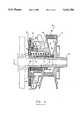
- FIG. 1is a cross sectional view of the driven pulley, according to the invention, with the upper half in a low rotation speed position and the lower half in a high rotation speed position.
- FIG. 2is a rear elevation view of the cam plate.
- FIG. 3is a perspective view of the cam plate with only one flyweight partially mounted thereon.
- FIG. 4is a perspective view of the rear of the movable flange.
- FIG. 5is a cross-sectional view of the driven pulley according to an alternative design of the invention.
- the driven pulleycomprise the following numbers:
- This pulley 10comprises:
- each flangehaving an inner conical wall, the inner walls facing each other and providing a V-shaped groove for a trapezoidal pulley belt exerting substantially a radial force and a tangential force on the inner walls, one of the flange, hereinafter called “fixed flange”, being rigidly attached at one end of the shaft, the other flange, hereinafter called “movable flange”, being slidably and rotatably mounted on the shaft;
- a helicoidal spring 50mounted around the shaft 40, forcing the movable flange to get closer to the fixed flange and preferably exerting an axial and a torsional return forces;
- the driven pulley 10is one of the parts of a variable speed transmission which substantially comprises a driving pulley (not shown), a trapezoidal belt 30 and the driven pulley 10.
- the driven pulley 10comprises a fixed flange 12 having an inner conical wall 14, and a movable flange 16 having an inner conical wall 18.
- the fixed flange 12 and the movable flange 16are coaxially mounted.
- the inner conical walls 14 and 18are facing each other and define a V-shaped groove 20.
- a trapezoidal belt 30is winded around substantially the half of the driven pulley 10, against the inner conical walls 14 and 18. Another portion of the trapezoidal belt 30 is winded around the driving pulley (not shown).
- the fixed flange 12is rigidly attached at one the ends of the shaft 40.
- the movable flange 16is slidably and rotatably mounted around the shaft 40 by means of a cylinder 42, located at the back of the movable flange 16 and rigidly attached thereon.
- the shaft 40may be mechanically connected to ground traction means (not shown), such as wheels, tracks or any other suitable mechanism.
- a cylindrical brass 44located between the shaft 40 and the cylinder 42, may be provided for preventing wear and reducing the friction.
- Means for providing a minimum spacing between the fixed flange 12 and the movable flange 16, such as a stopper 100,are provided for preventing the trapezoidal belt 30 from getting out of the driven pulley 10.
- a ring (not shown) of a suitable thicknessmay also be provided.
- This improvementconsists of:
- a substantially conical ring 70rotatably attached to the movable flange, on a side opposite its inner conical wall, the conical ring 70 having an inner edge 72 and an outer edge 74 where the inner edge 72 is farther from the fixed flange 12 than the outer edge 74;
- flyweightspreferably cylindrical flyweights 82, preferably three, symmetrically disposed around a plate rigidly attached to the shaft, each flyweight 82 being operatively attached to an arm, the arm being operatively attached to the plate and extending therefrom, each of the arm being able to revolve, about a tangential axis disposed at an edge of the plate, between a first position where the corresponding flyweight 82 projects substantially towards and against the annular conical surface 70 of the movable flange 16 and a second position where the corresponding flyweight 82 projects substantially radially with reference to the shaft 40; and
- biasing meansfor forcing the flyweights 82 to rest against the conical ring 70, the biasing means having an axial resultant force for moving the movable flange 16 closer to the fixed flange 12, the force being maximum at the first position.
- the flyweights 82are at the first position. As rotation speed increases, the flyweights 82 are subjected to a centrifugal force counterbalancing the means forcing the flyweights to rest against the conical ring 70, therefore reducing it and moving the flyweights closer to the second position.
- the conical ring 70is not having a constant angle. It may be curved or have two or more cone angles, thereby allowing a mechanical behaviour adapted to specific designs.
- the means to generate angular displacement of the movable flange 16 with respect to the fixed flange 12may comprise a cam plate 60 rigidly attached on the shaft 40 at the end opposite of the fixed flange 12.
- a helicoidal spring 50is coaxially mounted around the shaft 40 between the movable flange 16 and the cam plate 60.
- the cam plate 60may have three cam surfaces 62 symmetrically disposed around a circular path.
- the cam surfaces 62are curved to follow the circular path and progressively project toward the movable flange 16 in the direction of rotation of the driven pulley 10. It is not essential to have three cam surfaces 62, but two is the minimum number. Additionally, the cam surfaces 62 may have a non-constant ramp angle according to specific design requirements.
- three slider buttons 64are rigidly attached to the back of the movable flange 16, projecting therefrom towards the cam plate 60.
- the slider buttons 64are symmetrically disposed around a circular path substantially similar to the circular path of the cam surfaces 62.
- the number of slider buttons 64is equal to the number of cam surfaces 62.
- cam surfaces 62at the back of the movable flange 16 and the slider buttons 64 on the cam plate 60. It is also possible to have two sets of cam surfaces 62, one at the back of the movable flange 16 and the other on the cam plate 62, with conical rollers set in-between (not shown).
- the driven pulley 10changes its winding diameter of the trapezoidal belt 30 to keep an optimum ratio between the driving pulley and the driven pulley, thus compensate for the variation of the winding diameter of the driving pulley.
- the poweris transmitted from the driving pulley to the driven pulley 10 by a tangential force generated by the traction on the trapezoidal belt 30.
- Half of the poweris transmitted to the inner conical wall 14 and then to the shaft 40 by means of the fixed flange 12.
- the other half of the powergoes to shaft 40 through the inner conical wall 18, the movable flange 16, the slider buttons 64, the cam surfaces 62 and the cam plate 60.
- the tension in the trapezoidal belt 30increases.
- This tensionexerts a radial force, oriented towards the center of the driven pulley 10, on the inner conical walls 14 and 18. It thus force the movable flange 16 to move away from the fixed flange 12.
- the axial force exerted on the movable flange 16is counterbalanced by the helicoidal spring 50 and an axial component of the tangential force exerted by the trapezoidal belt 30 on the movable flange 16.
- the movable flange 16is moved away from the fixed flange 12 and the spring 50 is depressed until a new equilibrium between the spring force and the axial force generated by the trapezoidal belt 30. Each time the movable flange 16 moves, the winding diameter changes.
- the helicoidal spring 50may exert a torsional return force in addition to the axial return force.
- the torsional return forceis exerted in the direction of rotation and contributes to reset the flanges 12 and 16 closer to each other.
- the spring 50has a mechanical behaviour opposite to what it should be in an ideal driven pulley, which is to allow a maximum gripping force on the trapezoidal belt 30 when the winding diameter is maximum and a minimum gripping force when the winding diameter is minimum. This is due to the fact that the more a spring is depressed, the greater the return force becomes.
- an auxiliary deviceis provided to help the spring 50. As shown in FIG. 2, it comprises a set of three flyweight assemblies 80 symmetrically disposed around the cam plate 60, at the outer edge thereof. It is not essential to have three flyweight assemblies 80 but the minimum number is two for balancing purposes.
- Each flyweight assembly 80has a cylindrical flyweight 82 operatively attached to the cam plate 60 by a H-shaped arm 84, itself operatively attached to the cam plate 60, and extending therefrom, by means of a shaft 86.
- Two torsion springs 88coaxially mounted around the shaft 86 and each located at one side of the arm 84, force the flyweight 82 to rest against a conical ring 70 provided at the rear of the movable flange 16, near the outer edge 74 thereof, and facing the cam plate 60.
- One or more than two torsion springs 88may also be used.
- the conical ring 70is rotatably attached to the movable flange 16 for allowing free relative movement between the movable flange 16 and the flyweights 82 when the movable flange 16 is following the cam surface 62. It thus allows a low friction movement which do not interfere with the normal operation of the pulley.
- the conical ring 70is rolling on cylindrical rolls 76 and is maintained is place by screws 78 for preventing it from moving axially. Although balls (not shown) can be used instead of rolls, rolls are preferred because the forces is more evenly distributed.
- each flyweight 82has a contact surface 90 having a slightly larger diameter and centrally located thereon, as shown in FIGS. 2 and 3.
- each arm 84is able to revolve, about a tangential axis disposed at an edge of the cam plate 60, between a first position where the corresponding flyweight 82 projects substantially towards and against the conical ring 70 of the movable flange 16, and a second position where the corresponding flyweight 82 projects substantially radially with reference to the shaft 40.
- Each flyweight 82can turn freely on itself around its longitudinal axis.
- the flyweights 82In use, at low speeds, the flyweights 82 apply a force on the conical ring 70 and force the movable flange 16 to get closer to the fixed flange 12. At high speeds, the flyweights 82 are subjected to a centrifugal force counterbalancing the return force of the torsion springs 88 and therefore the flyweights 82 are brought closer to the second position as rotation speed increases.
- the flyweights 82are not in contact with the conical ring 70. However, this is not essential.
- the H-shaped arm 84is almost parallel to the shaft 40.
- the radial force exerted by the trapezoidal belt 30will then have to be very important to move the flyweights 82 from the first position. But as the rotation speed increases, so does the centrifugal force acting on the flyweights 82 and the movable flange 16 will then be easier to move by the trapezoidal belt 30 despite the return force generated by the torsion springs 88, which exert a force on the arm 84 to get the flyweights 82 to the first position. Yet, as the rotation speed increases, the action of the flyweight 82 is less important, thus exactly as it should be in a ideal driven pulley.
- the flyweights 82leave the conical ring 70. They reach the second position just after they took off and they remain there until the rotation speed is lower.
- flyweight assemblies 80With the use of the flyweight assemblies 80, it is now possible to use soft spring and still have a suitable gripping force at low speed.
- the use of the soft spring 50also allows to have a reasonably low gripping force at high speeds, therefore better efficiency.
- the position of the conical ring 70 and the flyweight assemblies 80may be inverted.
Landscapes
- Engineering & Computer Science (AREA)
- General Engineering & Computer Science (AREA)
- Mechanical Engineering (AREA)
- Transmissions By Endless Flexible Members (AREA)
Abstract
Description
Claims (12)
Priority Applications (1)
| Application Number | Priority Date | Filing Date | Title |
|---|---|---|---|
| US08/280,018US5421784A (en) | 1993-06-28 | 1994-07-25 | Driven pulley with flyweights effective at low speeds |
Applications Claiming Priority (2)
| Application Number | Priority Date | Filing Date | Title |
|---|---|---|---|
| US08/084,284US5358450A (en) | 1993-06-28 | 1993-06-28 | Driven pulley with flyweights effective at low speeds |
| US08/280,018US5421784A (en) | 1993-06-28 | 1994-07-25 | Driven pulley with flyweights effective at low speeds |
Related Parent Applications (1)
| Application Number | Title | Priority Date | Filing Date |
|---|---|---|---|
| US08/084,284Continuation-In-PartUS5358450A (en) | 1993-06-28 | 1993-06-28 | Driven pulley with flyweights effective at low speeds |
Publications (1)
| Publication Number | Publication Date |
|---|---|
| US5421784Atrue US5421784A (en) | 1995-06-06 |
Family
ID=46248611
Family Applications (1)
| Application Number | Title | Priority Date | Filing Date |
|---|---|---|---|
| US08/280,018Expired - LifetimeUS5421784A (en) | 1993-06-28 | 1994-07-25 | Driven pulley with flyweights effective at low speeds |
Country Status (1)
| Country | Link |
|---|---|
| US (1) | US5421784A (en) |
Cited By (21)
| Publication number | Priority date | Publication date | Assignee | Title |
|---|---|---|---|---|
| US5725446A (en)* | 1995-03-02 | 1998-03-10 | Kawasaki Jukogyo Kabushiki Kaisha | Belt-type automatic transmission |
| US5967286A (en)* | 1997-07-31 | 1999-10-19 | Starting Line Products, Inc. | Adjustable driven clutch |
| US6309317B1 (en) | 1998-01-28 | 2001-10-30 | Robert Joss | Centrifugal clutch shifter |
| US6569043B2 (en) | 1999-11-29 | 2003-05-27 | Team Industries, Inc. | Clutch with a one-way torque carrying bearing |
| EP1132656A3 (en)* | 2000-03-07 | 2004-03-03 | Honda Giken Kogyo Kabushiki Kaisha | V-belt-type automatic transmission for vehicle |
| US6743129B1 (en) | 1999-11-29 | 2004-06-01 | Team Industries, Inc. | Clutch with no relative rotation |
| US20040110583A1 (en)* | 2002-12-04 | 2004-06-10 | See-Bin Liang | Transmission system for motor bikes |
| US20090191788A1 (en)* | 2008-01-25 | 2009-07-30 | Timothy Seckel | Caster mounting arrangement for ride-on toy |
| US20110080805A1 (en)* | 2008-07-02 | 2011-04-07 | Chevron U.S.A., Inc. | Device and method for generating a beam of acoustic energy from a borehole, and applications thereof |
| US20110220453A1 (en)* | 2010-03-12 | 2011-09-15 | Team Industries, Inc. | Continuous variable clutch |
| US8668623B2 (en) | 2009-10-15 | 2014-03-11 | Team Industries, Inc. | Engine braking primary clutch for CVT systems |
| US20140349792A1 (en)* | 2011-08-31 | 2014-11-27 | Bombardier Recreational Products Inc. | Countinuously variable transmission drive pulley |
| US20150192191A1 (en)* | 2014-01-03 | 2015-07-09 | Sheng-Tsai Tseng | Vehicle transmission device |
| US20150267792A1 (en)* | 2012-09-28 | 2015-09-24 | Brp-Powertrain Gmbh & Co. Kg | Pneumatically assisted continuously variable transmission |
| US9644717B2 (en) | 2011-03-22 | 2017-05-09 | Bombardier Recreational Products Inc. | Continuously variable transmission driving pulley |
| ITUB20156886A1 (en)* | 2015-12-10 | 2017-06-10 | Piaggio & C Spa | TRANSMISSION DEVICE WITH CONTINUOUS CHANGE WITH CHANGE ADJUSTMENT DEVICE |
| US10174827B2 (en)* | 2017-02-21 | 2019-01-08 | Team Industries, Inc. | Drive clutch idle bearing torque drag assembly |
| US11105408B2 (en)* | 2016-09-21 | 2021-08-31 | Piaggio & C. S.P.A. | Continuously variable transmission device with device for varying the transmission curve |
| US11306809B2 (en)* | 2018-11-28 | 2022-04-19 | Bombardier Recreational Products Inc. | Drive pulley for a continuously variable transmission |
| US11680635B2 (en)* | 2020-02-25 | 2023-06-20 | Arctic Cat Inc. | Continuously variable transmission for recreational vehicles and related components |
| US20240410449A1 (en)* | 2023-06-06 | 2024-12-12 | David Randolph Forsyth | Cvt spider clutch with roller system |
Citations (11)
| Publication number | Priority date | Publication date | Assignee | Title |
|---|---|---|---|---|
| US3266330A (en)* | 1964-06-15 | 1966-08-16 | Clarence E Fleming Jr | Power transmission |
| US3638744A (en)* | 1969-04-18 | 1972-02-01 | Honda Motor Co Ltd | Vehicle speed-change and steering apparatus |
| US4284408A (en)* | 1978-09-08 | 1981-08-18 | Volvo Car B.V. | Automatic variable power transmission |
| US4464144A (en)* | 1981-03-10 | 1984-08-07 | Yamaha Hatsudoki Kabushiki Kaisha | V-belt type speed change mechanism |
| US4575363A (en)* | 1984-03-02 | 1986-03-11 | Bombardier Inc. | Drive pulley |
| US4634405A (en)* | 1982-12-13 | 1987-01-06 | Dayco Corporation | Pulley construction and method of making the same |
| JPS62110056A (en)* | 1985-11-07 | 1987-05-21 | Honda Motor Co Ltd | Drive pulley of V-belt continuously variable transmission |
| US4826467A (en)* | 1988-07-13 | 1989-05-02 | Club Car | Drive mechanism for a continuously variable transmission |
| US5326330A (en)* | 1992-05-12 | 1994-07-05 | Bombardier Inc. | Variable ratio drive pulley |
| US5328413A (en)* | 1993-06-28 | 1994-07-12 | Powerbloc Ibc Canada Inc. | Driving pulley |
| US5358450A (en)* | 1993-06-28 | 1994-10-25 | Powerbloc Ibc Canada Inc. | Driven pulley with flyweights effective at low speeds |
- 1994
- 1994-07-25USUS08/280,018patent/US5421784A/ennot_activeExpired - Lifetime
Patent Citations (11)
| Publication number | Priority date | Publication date | Assignee | Title |
|---|---|---|---|---|
| US3266330A (en)* | 1964-06-15 | 1966-08-16 | Clarence E Fleming Jr | Power transmission |
| US3638744A (en)* | 1969-04-18 | 1972-02-01 | Honda Motor Co Ltd | Vehicle speed-change and steering apparatus |
| US4284408A (en)* | 1978-09-08 | 1981-08-18 | Volvo Car B.V. | Automatic variable power transmission |
| US4464144A (en)* | 1981-03-10 | 1984-08-07 | Yamaha Hatsudoki Kabushiki Kaisha | V-belt type speed change mechanism |
| US4634405A (en)* | 1982-12-13 | 1987-01-06 | Dayco Corporation | Pulley construction and method of making the same |
| US4575363A (en)* | 1984-03-02 | 1986-03-11 | Bombardier Inc. | Drive pulley |
| JPS62110056A (en)* | 1985-11-07 | 1987-05-21 | Honda Motor Co Ltd | Drive pulley of V-belt continuously variable transmission |
| US4826467A (en)* | 1988-07-13 | 1989-05-02 | Club Car | Drive mechanism for a continuously variable transmission |
| US5326330A (en)* | 1992-05-12 | 1994-07-05 | Bombardier Inc. | Variable ratio drive pulley |
| US5328413A (en)* | 1993-06-28 | 1994-07-12 | Powerbloc Ibc Canada Inc. | Driving pulley |
| US5358450A (en)* | 1993-06-28 | 1994-10-25 | Powerbloc Ibc Canada Inc. | Driven pulley with flyweights effective at low speeds |
Cited By (32)
| Publication number | Priority date | Publication date | Assignee | Title |
|---|---|---|---|---|
| US5725446A (en)* | 1995-03-02 | 1998-03-10 | Kawasaki Jukogyo Kabushiki Kaisha | Belt-type automatic transmission |
| US5967286A (en)* | 1997-07-31 | 1999-10-19 | Starting Line Products, Inc. | Adjustable driven clutch |
| US6309317B1 (en) | 1998-01-28 | 2001-10-30 | Robert Joss | Centrifugal clutch shifter |
| US6569043B2 (en) | 1999-11-29 | 2003-05-27 | Team Industries, Inc. | Clutch with a one-way torque carrying bearing |
| US6743129B1 (en) | 1999-11-29 | 2004-06-01 | Team Industries, Inc. | Clutch with no relative rotation |
| EP1132656A3 (en)* | 2000-03-07 | 2004-03-03 | Honda Giken Kogyo Kabushiki Kaisha | V-belt-type automatic transmission for vehicle |
| US20040110583A1 (en)* | 2002-12-04 | 2004-06-10 | See-Bin Liang | Transmission system for motor bikes |
| US20090191788A1 (en)* | 2008-01-25 | 2009-07-30 | Timothy Seckel | Caster mounting arrangement for ride-on toy |
| US20110080805A1 (en)* | 2008-07-02 | 2011-04-07 | Chevron U.S.A., Inc. | Device and method for generating a beam of acoustic energy from a borehole, and applications thereof |
| US8668623B2 (en) | 2009-10-15 | 2014-03-11 | Team Industries, Inc. | Engine braking primary clutch for CVT systems |
| US20110220453A1 (en)* | 2010-03-12 | 2011-09-15 | Team Industries, Inc. | Continuous variable clutch |
| US8496551B2 (en) | 2010-03-12 | 2013-07-30 | Team Industries, Inc. | Continuous variable clutch |
| US9644717B2 (en) | 2011-03-22 | 2017-05-09 | Bombardier Recreational Products Inc. | Continuously variable transmission driving pulley |
| US20140349792A1 (en)* | 2011-08-31 | 2014-11-27 | Bombardier Recreational Products Inc. | Countinuously variable transmission drive pulley |
| US9267580B2 (en)* | 2011-08-31 | 2016-02-23 | Bombardier Recreational Products Inc. | Continuously variable transmission drive pulley |
| US20150267792A1 (en)* | 2012-09-28 | 2015-09-24 | Brp-Powertrain Gmbh & Co. Kg | Pneumatically assisted continuously variable transmission |
| US9476486B2 (en)* | 2012-09-28 | 2016-10-25 | Brp-Powertrain Gmbh & Co. Kg | Pneumatically assisted continuously variable transmission |
| US9333854B2 (en)* | 2014-01-03 | 2016-05-10 | Sheng-Tsai Tseng | Vehicle transmission device |
| US20150192191A1 (en)* | 2014-01-03 | 2015-07-09 | Sheng-Tsai Tseng | Vehicle transmission device |
| US11015697B2 (en)* | 2015-12-10 | 2021-05-25 | Piaggio & C. S.P.A. | Continuously variable transmission device with gear regulation device |
| WO2017098378A1 (en)* | 2015-12-10 | 2017-06-15 | Piaggio & C. S.P.A. | A continuously variable transmission device with gear regulation device |
| US20180355966A1 (en)* | 2015-12-10 | 2018-12-13 | Piaggio & C. S.P.A. | A continuously variable transmission device with gear regulation device |
| TWI707099B (en)* | 2015-12-10 | 2020-10-11 | 義大利商比雅久股份有限公司 | A continuously variable transmission device with gear regulation device and a continuously variable transmission system |
| ITUB20156886A1 (en)* | 2015-12-10 | 2017-06-10 | Piaggio & C Spa | TRANSMISSION DEVICE WITH CONTINUOUS CHANGE WITH CHANGE ADJUSTMENT DEVICE |
| US11105408B2 (en)* | 2016-09-21 | 2021-08-31 | Piaggio & C. S.P.A. | Continuously variable transmission device with device for varying the transmission curve |
| US10174827B2 (en)* | 2017-02-21 | 2019-01-08 | Team Industries, Inc. | Drive clutch idle bearing torque drag assembly |
| US11306809B2 (en)* | 2018-11-28 | 2022-04-19 | Bombardier Recreational Products Inc. | Drive pulley for a continuously variable transmission |
| US11680635B2 (en)* | 2020-02-25 | 2023-06-20 | Arctic Cat Inc. | Continuously variable transmission for recreational vehicles and related components |
| US20230279937A1 (en)* | 2020-02-25 | 2023-09-07 | Arctic Cat Inc. | Continuously variable transmission for recreational vehicles and related components |
| US12338886B2 (en)* | 2020-02-25 | 2025-06-24 | Arctic Cat Inc. | Continuously variable transmission for recreational vehicles and related components |
| US20240410449A1 (en)* | 2023-06-06 | 2024-12-12 | David Randolph Forsyth | Cvt spider clutch with roller system |
| US12305754B2 (en)* | 2023-06-06 | 2025-05-20 | David Randolph Forsyth | CVT spider clutch with roller system |
Similar Documents
| Publication | Publication Date | Title |
|---|---|---|
| US5421784A (en) | Driven pulley with flyweights effective at low speeds | |
| US5358450A (en) | Driven pulley with flyweights effective at low speeds | |
| US6520878B1 (en) | Driving pulley for scooters and other vehicles | |
| US6379274B1 (en) | Driven pulley | |
| US4826467A (en) | Drive mechanism for a continuously variable transmission | |
| EP1071893B1 (en) | Reversible driven pulley | |
| US6656068B2 (en) | Pulley having progressively variable sheave angle | |
| US5328413A (en) | Driving pulley | |
| US5458539A (en) | Flyweight with a lateral knob | |
| US5514040A (en) | Variable-speed belt drive having toothed flyweights | |
| US5580324A (en) | Driven pulley with a clutch | |
| US5108347A (en) | Speed variator pulley provided with a transmission membrane | |
| US5950488A (en) | Positive engagement continuously variable transmission | |
| EP1171729B1 (en) | Driving pulley for a continously variable transmission | |
| JP3162328B2 (en) | V-belt type automatic transmission for vehicles | |
| JPH04121566U (en) | variable speed pulley | |
| JPH0135973Y2 (en) | ||
| JP3694157B2 (en) | Auxiliary drive | |
| JP2707270B2 (en) | Striking prevention structure of belt type automatic transmission | |
| JPS63111353A (en) | Rotational control device | |
| JP3694156B2 (en) | Variable diameter pulley | |
| JPH037825B2 (en) | ||
| SU1618945A1 (en) | Stageless power transmission for vehicles | |
| CA2129791A1 (en) | Roller bearing for a movable flange | |
| CA2328432C (en) | Reversible driven pulley |
Legal Events
| Date | Code | Title | Description |
|---|---|---|---|
| AS | Assignment | Owner name:POWERBLOC IBC CANADA INC., CANADA Free format text:ASSIGNMENT OF ASSIGNORS INTEREST;ASSIGNOR:ROBERT, JEAN;REEL/FRAME:007098/0061 Effective date:19940712 | |
| STCF | Information on status: patent grant | Free format text:PATENTED CASE | |
| FEPP | Fee payment procedure | Free format text:PAYOR NUMBER ASSIGNED (ORIGINAL EVENT CODE: ASPN); ENTITY STATUS OF PATENT OWNER: SMALL ENTITY | |
| REMI | Maintenance fee reminder mailed | ||
| FPAY | Fee payment | Year of fee payment:4 | |
| SULP | Surcharge for late payment | ||
| FEPP | Fee payment procedure | Free format text:PAYOR NUMBER ASSIGNED (ORIGINAL EVENT CODE: ASPN); ENTITY STATUS OF PATENT OWNER: SMALL ENTITY Free format text:PAYER NUMBER DE-ASSIGNED (ORIGINAL EVENT CODE: RMPN); ENTITY STATUS OF PATENT OWNER: SMALL ENTITY | |
| FPAY | Fee payment | Year of fee payment:8 | |
| AS | Assignment | Owner name:CVTECH-R&D INC., CANADA Free format text:ASSIGNMENT OF ASSIGNORS INTEREST;ASSIGNOR:POWERBLOC IBC CANADA INC.;REEL/FRAME:013751/0257 Effective date:20030121 | |
| FPAY | Fee payment | Year of fee payment:12 |