US5421338A - Acoustic imaging catheter and the like - Google Patents
Acoustic imaging catheter and the likeDownload PDFInfo
- Publication number
- US5421338A US5421338AUS08/253,629US25362994AUS5421338AUS 5421338 AUS5421338 AUS 5421338AUS 25362994 AUS25362994 AUS 25362994AUS 5421338 AUS5421338 AUS 5421338A
- Authority
- US
- United States
- Prior art keywords
- balloon
- catheter body
- ultrasonic probe
- drive shaft
- lumen
- Prior art date
- Legal status (The legal status is an assumption and is not a legal conclusion. Google has not performed a legal analysis and makes no representation as to the accuracy of the status listed.)
- Expired - Lifetime
Links
- 238000003384imaging methodMethods0.000titleclaimsabstractdescription160
- 239000000523sampleSubstances0.000claimsabstractdescription204
- 238000002604ultrasonographyMethods0.000claimsabstractdescription102
- 239000007788liquidSubstances0.000claimsabstractdescription17
- 238000010276constructionMethods0.000claimsabstractdescription8
- 238000011282treatmentMethods0.000claimsdescription131
- 239000012530fluidSubstances0.000claimsdescription91
- 238000000034methodMethods0.000claimsdescription44
- 230000033001locomotionEffects0.000claimsdescription41
- 239000000463materialSubstances0.000claimsdescription35
- 210000004204blood vesselAnatomy0.000claimsdescription28
- 238000010438heat treatmentMethods0.000claimsdescription24
- 238000007789sealingMethods0.000claimsdescription21
- 210000001519tissueAnatomy0.000claimsdescription20
- 238000002399angioplastyMethods0.000claimsdescription13
- 230000001225therapeutic effectEffects0.000claimsdescription12
- FAPWRFPIFSIZLT-UHFFFAOYSA-MSodium chlorideChemical compound[Na+].[Cl-]FAPWRFPIFSIZLT-UHFFFAOYSA-M0.000claimsdescription11
- -1polyethylenePolymers0.000claimsdescription11
- 239000004698PolyethyleneSubstances0.000claimsdescription9
- 229920000573polyethylenePolymers0.000claimsdescription9
- 230000000694effectsEffects0.000claimsdescription8
- 238000003780insertionMethods0.000claimsdescription7
- 230000037431insertionEffects0.000claimsdescription7
- 238000012545processingMethods0.000claimsdescription7
- 210000002307prostateAnatomy0.000claimsdescription7
- 238000013022ventingMethods0.000claimsdescription7
- 210000003238esophagusAnatomy0.000claimsdescription6
- 230000002792vascularEffects0.000claimsdescription6
- 238000010168coupling processMethods0.000claimsdescription5
- 238000005859coupling reactionMethods0.000claimsdescription5
- 239000007787solidSubstances0.000claimsdescription4
- 238000003860storageMethods0.000claimsdescription3
- 230000008878couplingEffects0.000claimsdescription2
- 239000013536elastomeric materialSubstances0.000claimsdescription2
- 238000011010flushing procedureMethods0.000claimsdescription2
- 239000000203mixtureSubstances0.000claimsdescription2
- 230000000977initiatory effectEffects0.000claims6
- 230000002452interceptive effectEffects0.000abstractdescription3
- 230000002708enhancing effectEffects0.000abstractdescription2
- 238000002347injectionMethods0.000abstractdescription2
- 239000007924injectionSubstances0.000abstractdescription2
- 238000011068loading methodMethods0.000abstractdescription2
- 208000018672DilatationDiseases0.000description45
- 206010028980NeoplasmDiseases0.000description17
- 238000012285ultrasound imagingMethods0.000description11
- 208000027418Wounds and injuryDiseases0.000description10
- 210000001367arteryAnatomy0.000description8
- 238000011049fillingMethods0.000description7
- 239000011780sodium chlorideSubstances0.000description7
- XLYOFNOQVPJJNP-UHFFFAOYSA-NwaterChemical compoundOXLYOFNOQVPJJNP-UHFFFAOYSA-N0.000description7
- 238000001574biopsyMethods0.000description6
- 230000006835compressionEffects0.000description6
- 238000007906compressionMethods0.000description6
- 238000007689inspectionMethods0.000description6
- 229910052751metalInorganic materials0.000description6
- 239000002184metalSubstances0.000description6
- 238000005070samplingMethods0.000description6
- 238000012544monitoring processMethods0.000description5
- 208000031481Pathologic ConstrictionDiseases0.000description4
- 230000008901benefitEffects0.000description4
- 238000003745diagnosisMethods0.000description4
- 230000010339dilationEffects0.000description4
- 210000004907glandAnatomy0.000description4
- 210000004185liverAnatomy0.000description4
- 230000002093peripheral effectEffects0.000description4
- 210000005070sphincterAnatomy0.000description4
- 210000003813thumbAnatomy0.000description4
- 239000004593EpoxySubstances0.000description3
- BQCADISMDOOEFD-UHFFFAOYSA-NSilverChemical compound[Ag]BQCADISMDOOEFD-UHFFFAOYSA-N0.000description3
- 239000004020conductorSubstances0.000description3
- 210000004351coronary vesselAnatomy0.000description3
- 238000001514detection methodMethods0.000description3
- 238000010586diagramMethods0.000description3
- 238000006073displacement reactionMethods0.000description3
- 210000001105femoral arteryAnatomy0.000description3
- 210000003709heart valveAnatomy0.000description3
- 239000012212insulatorSubstances0.000description3
- 230000008569processEffects0.000description3
- 230000005855radiationEffects0.000description3
- 230000004044responseEffects0.000description3
- 229910052709silverInorganic materials0.000description3
- 239000004332silverSubstances0.000description3
- 229910001220stainless steelInorganic materials0.000description3
- 239000010935stainless steelSubstances0.000description3
- 230000009471actionEffects0.000description2
- 239000000853adhesiveSubstances0.000description2
- 230000001070adhesive effectEffects0.000description2
- 238000004873anchoringMethods0.000description2
- 230000000712assemblyEffects0.000description2
- 238000000429assemblyMethods0.000description2
- 230000005540biological transmissionEffects0.000description2
- 230000015572biosynthetic processEffects0.000description2
- 239000008280bloodSubstances0.000description2
- 210000004369bloodAnatomy0.000description2
- 210000000481breastAnatomy0.000description2
- 239000011248coating agentSubstances0.000description2
- 238000000576coating methodMethods0.000description2
- 238000004891communicationMethods0.000description2
- 239000013078crystalSubstances0.000description2
- 210000003414extremityAnatomy0.000description2
- 230000006870functionEffects0.000description2
- 210000003090iliac arteryAnatomy0.000description2
- 230000013011matingEffects0.000description2
- 238000005259measurementMethods0.000description2
- 210000000056organAnatomy0.000description2
- 239000008188pelletSubstances0.000description2
- 230000006461physiological responseEffects0.000description2
- 229920001296polysiloxanePolymers0.000description2
- 230000002285radioactive effectEffects0.000description2
- 238000010561standard procedureMethods0.000description2
- 230000002966stenotic effectEffects0.000description2
- 238000004804windingMethods0.000description2
- OYPRJOBELJOOCE-UHFFFAOYSA-NCalciumChemical compound[Ca]OYPRJOBELJOOCE-UHFFFAOYSA-N0.000description1
- OKTJSMMVPCPJKN-UHFFFAOYSA-NCarbonChemical compound[C]OKTJSMMVPCPJKN-UHFFFAOYSA-N0.000description1
- 208000012661DyskinesiaDiseases0.000description1
- 102000004190EnzymesHuman genes0.000description1
- 108090000790EnzymesProteins0.000description1
- 206010020843HyperthermiaDiseases0.000description1
- 239000004677NylonSubstances0.000description1
- 206010060862Prostate cancerDiseases0.000description1
- 102000003990Urokinase-type plasminogen activatorHuman genes0.000description1
- 108090000435Urokinase-type plasminogen activatorProteins0.000description1
- 230000002745absorbentEffects0.000description1
- 239000002250absorbentSubstances0.000description1
- 230000001154acute effectEffects0.000description1
- 210000000436anusAnatomy0.000description1
- 210000002376aorta thoracicAnatomy0.000description1
- 230000035045associative learningEffects0.000description1
- 230000004323axial lengthEffects0.000description1
- 229910052788bariumInorganic materials0.000description1
- DSAJWYNOEDNPEQ-UHFFFAOYSA-Nbarium atomChemical compound[Ba]DSAJWYNOEDNPEQ-UHFFFAOYSA-N0.000description1
- 238000005452bendingMethods0.000description1
- 230000009286beneficial effectEffects0.000description1
- 210000003445biliary tractAnatomy0.000description1
- 238000007664blowingMethods0.000description1
- 210000001124body fluidAnatomy0.000description1
- 239000010839body fluidSubstances0.000description1
- 229910052791calciumInorganic materials0.000description1
- 239000011575calciumSubstances0.000description1
- 229910052799carbonInorganic materials0.000description1
- 210000001715carotid arteryAnatomy0.000description1
- 229910010293ceramic materialInorganic materials0.000description1
- 230000008859changeEffects0.000description1
- 210000001072colonAnatomy0.000description1
- 239000002872contrast mediaSubstances0.000description1
- 238000005336crackingMethods0.000description1
- 230000000881depressing effectEffects0.000description1
- 238000000502dialysisMethods0.000description1
- 201000010099diseaseDiseases0.000description1
- 208000037265diseases, disorders, signs and symptomsDiseases0.000description1
- 229920001971elastomerPolymers0.000description1
- 239000000806elastomerSubstances0.000description1
- 229940088598enzymeDrugs0.000description1
- 229920006333epoxy cementPolymers0.000description1
- 239000003000extruded plasticSubstances0.000description1
- 238000001125extrusionMethods0.000description1
- 238000000227grindingMethods0.000description1
- 229920005669high impact polystyrenePolymers0.000description1
- 239000004797high-impact polystyreneSubstances0.000description1
- 230000036031hyperthermiaEffects0.000description1
- 238000001746injection mouldingMethods0.000description1
- 239000011810insulating materialSubstances0.000description1
- 230000001788irregularEffects0.000description1
- 230000003902lesionEffects0.000description1
- 201000007270liver cancerDiseases0.000description1
- 208000014018liver neoplasmDiseases0.000description1
- 230000001050lubricating effectEffects0.000description1
- 238000004519manufacturing processMethods0.000description1
- 239000007769metal materialSubstances0.000description1
- 238000000465mouldingMethods0.000description1
- 208000025402neoplasm of esophagusDiseases0.000description1
- 229920001778nylonPolymers0.000description1
- 238000010943off-gassingMethods0.000description1
- 230000003287optical effectEffects0.000description1
- 230000000149penetrating effectEffects0.000description1
- 230000004962physiological conditionEffects0.000description1
- 229920002981polyvinylidene fluoridePolymers0.000description1
- 210000003137popliteal arteryAnatomy0.000description1
- 238000002360preparation methodMethods0.000description1
- 201000001514prostate carcinomaDiseases0.000description1
- 238000005086pumpingMethods0.000description1
- 238000010926purgeMethods0.000description1
- 238000004064recyclingMethods0.000description1
- 230000009467reductionEffects0.000description1
- 210000002254renal arteryAnatomy0.000description1
- 239000012261resinous substanceSubstances0.000description1
- 210000000952spleenAnatomy0.000description1
- 239000003381stabilizerSubstances0.000description1
- 239000008223sterile waterSubstances0.000description1
- 239000000126substanceSubstances0.000description1
- 238000002560therapeutic procedureMethods0.000description1
- 239000012815thermoplastic materialSubstances0.000description1
- 210000003437tracheaAnatomy0.000description1
- 230000002463transducing effectEffects0.000description1
- 238000012546transferMethods0.000description1
- 230000001131transforming effectEffects0.000description1
- 210000003708urethraAnatomy0.000description1
- 230000002485urinary effectEffects0.000description1
- 229960005356urokinaseDrugs0.000description1
Images


Classifications
- A—HUMAN NECESSITIES
- A61—MEDICAL OR VETERINARY SCIENCE; HYGIENE
- A61B—DIAGNOSIS; SURGERY; IDENTIFICATION
- A61B5/00—Measuring for diagnostic purposes; Identification of persons
- A61B5/68—Arrangements of detecting, measuring or recording means, e.g. sensors, in relation to patient
- A61B5/6846—Arrangements of detecting, measuring or recording means, e.g. sensors, in relation to patient specially adapted to be brought in contact with an internal body part, i.e. invasive
- A61B5/6847—Arrangements of detecting, measuring or recording means, e.g. sensors, in relation to patient specially adapted to be brought in contact with an internal body part, i.e. invasive mounted on an invasive device
- A61B5/6848—Needles
- A—HUMAN NECESSITIES
- A61—MEDICAL OR VETERINARY SCIENCE; HYGIENE
- A61B—DIAGNOSIS; SURGERY; IDENTIFICATION
- A61B18/00—Surgical instruments, devices or methods for transferring non-mechanical forms of energy to or from the body
- A61B18/04—Surgical instruments, devices or methods for transferring non-mechanical forms of energy to or from the body by heating
- A61B18/12—Surgical instruments, devices or methods for transferring non-mechanical forms of energy to or from the body by heating by passing a current through the tissue to be heated, e.g. high-frequency current
- A61B18/14—Probes or electrodes therefor
- A61B18/1492—Probes or electrodes therefor having a flexible, catheter-like structure, e.g. for heart ablation
- A—HUMAN NECESSITIES
- A61—MEDICAL OR VETERINARY SCIENCE; HYGIENE
- A61B—DIAGNOSIS; SURGERY; IDENTIFICATION
- A61B5/00—Measuring for diagnostic purposes; Identification of persons
- A61B5/41—Detecting, measuring or recording for evaluating the immune or lymphatic systems
- A61B5/414—Evaluating particular organs or parts of the immune or lymphatic systems
- A61B5/416—Evaluating particular organs or parts of the immune or lymphatic systems the spleen
- A—HUMAN NECESSITIES
- A61—MEDICAL OR VETERINARY SCIENCE; HYGIENE
- A61B—DIAGNOSIS; SURGERY; IDENTIFICATION
- A61B8/00—Diagnosis using ultrasonic, sonic or infrasonic waves
- A61B8/12—Diagnosis using ultrasonic, sonic or infrasonic waves in body cavities or body tracts, e.g. by using catheters
- A—HUMAN NECESSITIES
- A61—MEDICAL OR VETERINARY SCIENCE; HYGIENE
- A61B—DIAGNOSIS; SURGERY; IDENTIFICATION
- A61B8/00—Diagnosis using ultrasonic, sonic or infrasonic waves
- A61B8/44—Constructional features of the ultrasonic, sonic or infrasonic diagnostic device
- A61B8/4444—Constructional features of the ultrasonic, sonic or infrasonic diagnostic device related to the probe
- A61B8/445—Details of catheter construction
- A—HUMAN NECESSITIES
- A61—MEDICAL OR VETERINARY SCIENCE; HYGIENE
- A61B—DIAGNOSIS; SURGERY; IDENTIFICATION
- A61B8/00—Diagnosis using ultrasonic, sonic or infrasonic waves
- A61B8/44—Constructional features of the ultrasonic, sonic or infrasonic diagnostic device
- A61B8/4444—Constructional features of the ultrasonic, sonic or infrasonic diagnostic device related to the probe
- A61B8/4461—Features of the scanning mechanism, e.g. for moving the transducer within the housing of the probe
- A—HUMAN NECESSITIES
- A61—MEDICAL OR VETERINARY SCIENCE; HYGIENE
- A61B—DIAGNOSIS; SURGERY; IDENTIFICATION
- A61B10/00—Instruments for taking body samples for diagnostic purposes; Other methods or instruments for diagnosis, e.g. for vaccination diagnosis, sex determination or ovulation-period determination; Throat striking implements
- A61B10/02—Instruments for taking cell samples or for biopsy
- A61B10/0291—Instruments for taking cell samples or for biopsy for uterus
- A—HUMAN NECESSITIES
- A61—MEDICAL OR VETERINARY SCIENCE; HYGIENE
- A61B—DIAGNOSIS; SURGERY; IDENTIFICATION
- A61B17/00—Surgical instruments, devices or methods
- A61B17/34—Trocars; Puncturing needles
- A—HUMAN NECESSITIES
- A61—MEDICAL OR VETERINARY SCIENCE; HYGIENE
- A61B—DIAGNOSIS; SURGERY; IDENTIFICATION
- A61B17/00—Surgical instruments, devices or methods
- A61B17/22—Implements for squeezing-off ulcers or the like on inner organs of the body; Implements for scraping-out cavities of body organs, e.g. bones; for invasive removal or destruction of calculus using mechanical vibrations; for removing obstructions in blood vessels, not otherwise provided for
- A61B2017/22072—Implements for squeezing-off ulcers or the like on inner organs of the body; Implements for scraping-out cavities of body organs, e.g. bones; for invasive removal or destruction of calculus using mechanical vibrations; for removing obstructions in blood vessels, not otherwise provided for with an instrument channel, e.g. for replacing one instrument by the other
- A61B2017/22078—Implements for squeezing-off ulcers or the like on inner organs of the body; Implements for scraping-out cavities of body organs, e.g. bones; for invasive removal or destruction of calculus using mechanical vibrations; for removing obstructions in blood vessels, not otherwise provided for with an instrument channel, e.g. for replacing one instrument by the other for rotating the instrument within a channel, e.g. an optical fibre
- A—HUMAN NECESSITIES
- A61—MEDICAL OR VETERINARY SCIENCE; HYGIENE
- A61B—DIAGNOSIS; SURGERY; IDENTIFICATION
- A61B18/00—Surgical instruments, devices or methods for transferring non-mechanical forms of energy to or from the body
- A61B2018/00053—Mechanical features of the instrument of device
- A61B2018/00184—Moving parts
- A61B2018/00202—Moving parts rotating
- A61B2018/00208—Moving parts rotating actively driven, e.g. by a motor
- A—HUMAN NECESSITIES
- A61—MEDICAL OR VETERINARY SCIENCE; HYGIENE
- A61B—DIAGNOSIS; SURGERY; IDENTIFICATION
- A61B18/00—Surgical instruments, devices or methods for transferring non-mechanical forms of energy to or from the body
- A61B2018/00053—Mechanical features of the instrument of device
- A61B2018/00214—Expandable means emitting energy, e.g. by elements carried thereon
- A—HUMAN NECESSITIES
- A61—MEDICAL OR VETERINARY SCIENCE; HYGIENE
- A61B—DIAGNOSIS; SURGERY; IDENTIFICATION
- A61B18/00—Surgical instruments, devices or methods for transferring non-mechanical forms of energy to or from the body
- A61B2018/00636—Sensing and controlling the application of energy
- A61B2018/00898—Alarms or notifications created in response to an abnormal condition
- A—HUMAN NECESSITIES
- A61—MEDICAL OR VETERINARY SCIENCE; HYGIENE
- A61B—DIAGNOSIS; SURGERY; IDENTIFICATION
- A61B18/00—Surgical instruments, devices or methods for transferring non-mechanical forms of energy to or from the body
- A61B18/18—Surgical instruments, devices or methods for transferring non-mechanical forms of energy to or from the body by applying electromagnetic radiation, e.g. microwaves
- A61B18/1815—Surgical instruments, devices or methods for transferring non-mechanical forms of energy to or from the body by applying electromagnetic radiation, e.g. microwaves using microwaves
- A61B2018/1861—Surgical instruments, devices or methods for transferring non-mechanical forms of energy to or from the body by applying electromagnetic radiation, e.g. microwaves using microwaves with an instrument inserted into a body lumen or cavity, e.g. a catheter
- A—HUMAN NECESSITIES
- A61—MEDICAL OR VETERINARY SCIENCE; HYGIENE
- A61B—DIAGNOSIS; SURGERY; IDENTIFICATION
- A61B90/00—Instruments, implements or accessories specially adapted for surgery or diagnosis and not covered by any of the groups A61B1/00 - A61B50/00, e.g. for luxation treatment or for protecting wound edges
- A61B90/36—Image-producing devices or illumination devices not otherwise provided for
- A61B90/37—Surgical systems with images on a monitor during operation
- A61B2090/378—Surgical systems with images on a monitor during operation using ultrasound
- A61B2090/3782—Surgical systems with images on a monitor during operation using ultrasound transmitter or receiver in catheter or minimal invasive instrument
- A—HUMAN NECESSITIES
- A61—MEDICAL OR VETERINARY SCIENCE; HYGIENE
- A61M—DEVICES FOR INTRODUCING MEDIA INTO, OR ONTO, THE BODY; DEVICES FOR TRANSDUCING BODY MEDIA OR FOR TAKING MEDIA FROM THE BODY; DEVICES FOR PRODUCING OR ENDING SLEEP OR STUPOR
- A61M25/00—Catheters; Hollow probes
- A61M25/10—Balloon catheters
- A61M25/104—Balloon catheters used for angioplasty
Definitions
- This inventionrelates to acoustic imaging catheters employing a rotating transducer.
- the inventionfeatures an acoustic imaging catheter device, that has a flexible, axially elongated ultrasonic probe formed of a rotatable drive shaft with an ultrasonic transducer at its distal end, a catheter body in the form of an elongated, resinous, flexible member, and an inflatable balloon disposed on the catheter body, the catheter body having a distal portion extending distally beyond the balloon.
- the material of the balloon, the portion of the catheter body carrying the balloon and the distal portion of the catheter body beyond the balloonare sonolucent and substantially matched in acoustic impedance with fluid to which the catheter is exposed.
- a probe receiving passage within the catheter bodyis constructed and arranged to rotatably slidably support the elongated ultrasonic probe at rotational speed enabling generation of acoustic images.
- the catheter body and flexible ultrasonic probeare cooperatively constructed and arranged to enable axial sliding motion of the probe within the catheter body to position the transducer between at least two positions, one position located in the distal portion of the catheter, distal to the balloon, for providing an image of the wall of a body lumen in which the device is inserted to locate a region of the lumen wall requiring treatment or for viewing the lumen wall after treatment, and the other position located in the region of the catheter corresponding to the balloon, enabling viewing of the lumen wall while the balloon applies treatment conditions to the lumen wall.
- the transduceris variably positionable in the catheter along the length of the balloon.
- the transduceris also positionable in a region of the catheter proximal to the balloon, the proximal region of the catheter body being sonolucent and substantially matched in acoustic impedance with fluid to which the catheter is exposed.
- the transduceris variably positionable from a region of the catheter proximal to the balloon, to a region distal to the balloon.
- the catheter deviceincludes a position detector means adapted to detect the axial position of the transducer within the catheter body and processing means to provide an image of the body lumen as a function of the axial position and acoustic image information obtained during rotation of the transducer.
- the processing meansincludes storage means to store acoustic image information from selected axial positions of the catheter body and image reconstruction means to provide therefrom a three-dimensional image of the body lumen.
- the processing meansis constructed and arranged to provide a three-dimensional image of the body lumen corresponding to a range of axial travel of the transducer in the catheter.
- the inventionfeatures an acoustic imaging catheter device capable of treatment of a body lumen having a flexible axially elongated ultrasonic probe comprising a rotatable drive shaft with an ultrasonic transducer at its distal end, a catheter body in the form of an elongated, resinous, flexible member, and an inflatable treatment balloon constructed and arranged on the catheter to apply a therapeutic treatment to a portion of the human body which the balloon contacts.
- the material of the balloon, and the portion of the catheter body carrying the balloonare sonolucent and substantially matched in acoustic impedance with fluid to which the catheter is exposed.
- a probe receiving passage within the catheter bodyis constructed and arranged to rotatably slidably support the elongated ultrasonic probe at rotational speed enabling generation of acoustic images.
- the transducerhas a position within the catheter at the location of the balloon, and is arranged to form acoustic images of the portion of the body contacted by the treatment balloon during the progress of the treatment.
- the treatment balloonis an inflatable dilatation balloon disposed on the catheter body, the wall of the balloon being comprised of non-elastomeric material resistant to substantial stretching under the dilatation pressure.
- the treatment balloonis associated with heating means heating inflation liquid within the balloon to controlled treatment temperature.
- the heating meansincludes electrodes connectable to a radio frequency energy source capable of heating electrically conductive liquid in the balloon on the basis of I 2 R losses.
- the catheter bodyhas a single probe-receiving lumen constructed and arranged to slidably receive and support the elongated ultrasonic probe in a rotatable manner.
- the probe-receiving lumenis constructed to convey inflation fluid from a dilatation pressure source to the interior of the balloon to inflate the balloon to dilatation pressure.
- the catheter body and flexible ultrasonic probeare cooperatively constructed and arranged to enable positioning of the transducer in a region of the catheter axially corresponding to the balloon for observing a region of the body simultaneously while treatment thereof is being performed by the balloon.
- the catheter bodyhas a distal portion extending distally from the balloon.
- the distal portion of the catheter bodybeing sonolucent and substantially matched in acoustic impedance with fluid to which the catheter is exposed, and the catheter body and flexible ultrasonic probe cooperatively constructed and arranged to enable axial sliding motion of the probe within the catheter body to position the transducer between at least two positions, one position located at the distal portion of the catheter, distal to the balloon, for providing an image of the wall of a body lumen in which the device is inserted to locate a region of the lumen wall requiring treatment or for viewing the lumen wall requiring treatment or for viewing the lumen wall after treatment and the other position located in the region of the catheter corresponding to the balloon, enabling viewing tissue while the balloon applies treatment conditions to the lumen wall.
- the devicefurther includes an inflation means comprising a screw syringe for generating dilatation pressures in the balloon.
- the catheter bodyextends through the full length of the balloon and includes a fluid port in the region of the balloon for inflating the balloon and equalization of pressure in the balloon and the catheter body.
- the sonolucent portion of the catheter bodyhas a wall thickness of about 0.010 inch or less.
- the deviceincludes further a saddle member of limited axial extent fixed to the exterior of a portion of the catheter body corresponding to the location of the balloon.
- the saddleincludes a lumen enabling passage of a guidewire along the exterior of the catheter body through the balloon, with portions of the guidewire proximal and distal of the balloon being exposed to the body lumen.
- the distal catheter extensionincludes a first aperture in the side wall and a second aperture, axially arranged in the distal end of the extension and the guidewire is threaded through the first and second apertures to extend distally from the device.
- the tubular saddle memberis sonolucent and substantially matched in acoustic impedance with fluid to which the catheter is exposed.
- the tubular memberis formed of polyethylene.
- the deviceincludes a sealing member at the proximal portion of the catheter apparatus including a low friction seal in contact with the drive shaft for preventing flow of inflation fluids to distal portions of the drive shaft at dilatation pressures, while enabling rotation thereof.
- the drive shaft and sealing memberare cooperatively constructed to enable axial motion of the transducer with respect to the catheter sheath.
- the sealing memberincludes a ball seal contacting a portion of the drive shaft and enabling rotation thereof while preventing flow of inflation fluids proximal to the ball seal.
- the balloonis formed of polyethylene.
- the deviceis sized and constructed for treatment in the vascular system.
- the deviceis sized and constructed for balloon angioplasty.
- the deviceis sized and constructed for treatment in the esophagus.
- the deviceis sized and constructed for treatment in the prostate.
- the devicefurther includes a self-sealing septum enabling venting of the catheter body.
- the septumis adapted for venting inflation fluid, provided to the catheter body in excess to prepare the catheter for use.
- the septumis adapted for venting air, when inflation fluid is provided to the catheter body in excess to prepare the catheter for use.
- the entire length of the catheter bodyis sonolucent.
- the deviceincludes means for asymmetric treatment of the vessel.
- the means for asymmetric treatmentincludes means for asymmetric heating.
- the asymmetric meansincludes multiple balloons arranged to provide asymmetric heating.
- the meansincludes an asymmetric balloon.
- the catheter bodyincludes a bellows enabling extension and retraction of the body with respect to the transducer.
- the inventionalso features an acoustic imaging catheter device having a flexible elongated ultrasonic probe comprising a rotatable drive shaft with an ultrasonic transducer at its distal end, a catheter body in the form of an elongated, resinous, flexible member, and an inflatable balloon disposed on the catheter body, the catheter body has a distal portion extending distally from the balloon.
- the distal portion of the catheter bodyis sonolucent and substantially matched in acoustic impedance with fluid to which the catheter is exposed, and a passage within the catheter body is constructed and arranged to slidably receive and support the elongated ultrasonic probe in a rotatable manner.
- the catheter body and flexible ultrasonic probeare cooperatively constructed and arranged to position the probe within the catheter body to position the transducer in the sonolucent catheter extension for providing an image of the wall of a body lumen in which the device is inserted, to locate a region of the lumen wall requiring treatment or for viewing the lumen wall after treatment.
- the inventionfeatures an acoustic imaging dilatation device having a flexible elongated ultrasonic probe comprising a rotatable drive shaft with an ultrasonic transducer at its distal end, a catheter body in the form of an elongated, resinous, flexible member capable of withstanding dilatation pressures of 100 psi or more, and an inflatable balloon disposed on the catheter body, inflatable to the dilatation pressure, and being comprised of nonelastomeric material resistant to substantial stretching under the dilatation pressure.
- a distal portion of the catheter body in the vicinity of the balloonis sonolucent and substantially matched in acoustic impedance with fluid to which the catheter is exposed, and a passage within the catheter body is constructed and arranged to receive and support the elongated ultrasonic probe in a rotatable manner.
- the catheter body and flexible ultrasonic probeare cooperatively constructed and arranged to position the probe within the catheter body to position the transducer in the sonolucent catheter portion for providing an image of the wall of a body lumen in which the device is inserted.
- the catheter bodyis a single lumen catheter body adapted to receive the probe and connected to a source of dilatation pressure for inflation of the balloon.
- the sonolucent portion of the catheter bodycorresponds with the location of the balloon.
- the sonolucent portionis a distal extension of the catheter, distal to the balloon.
- the catheter bodyextends the length of the balloon and includes a fluid port in the region of the balloon for inflation of the balloon and equalization of pressure in the balloon and catheter body.
- the catheter bodyhas a distal portion extending distally from the balloon.
- the distal portion of the catheter bodyis sonolucent and substantially matched in acoustic impedance with fluid to which the catheter is exposed, and the catheter body and flexible ultrasonic probe are cooperatively constructed and arranged to enable axial sliding motion of the probe within the catheter body to position the transducer between at least two positions.
- One positionis located at the distal portion of the catheter, distal to the balloon, for providing an image of the wall of a body lumen in which the device is inserted to locate a region of the lumen wall requiring treatment or for viewing the lumen wall after treatment, and the other position is located in the region of the catheter corresponding to the balloon, enabling viewing of the lumen wall while the balloon applies treatment conditions to the lumen wall.
- the inventionfeatures an acoustic imaging catheter device having a closed, continuous catheter body in the form of an elongated, resinous, flexible member containing therein a pressurized fluid. At least the distal portion of the catheter body is sonolucent and substantially matched in acoustic impedance with fluid to which the catheter is exposed.
- a flexible elongated ultrasonic probeis provided comprising a rotatable drive shaft with an ultrasonic transducer at its distal end. The transducer has an outer diameter corresponding to the outer diameter of the drive shaft and mounted coaxially therewith.
- the drive shaft and transducer headforming a core that can be slidably inserted via the proximal end into the tubular body having a closed distal end to a directly, rotatably supported relationship with the body and after use can be slidably removed from the catheter body for repeated re-use in other catheter bodies.
- a sealing memberis provided at the proximal portion of the catheter apparatus including a low friction seal in contact with the drive shaft for preventing flow of fluids to distal portions of the drive shaft, while enabling rotation thereof.
- the catheter body, sealing member and flexible ultrasonic probeare cooperatively constructed and arranged to enable axial sliding motion of the probe within the catheter body to position the transducer between positions in the acoustically transparent regions of the catheter body sheath for providing an image of the wall of a body lumen to locate a region requiring treatment.
- a medical deviceis actuateable by the pressurized fluid.
- the inventionfeatures a method for balloon dilatation.
- the methodincludes providing a balloon dilatation acoustic imaging device including a flexible elongated ultrasonic probe comprising a rotatable drive shaft with an ultrasonic transducer at its distal end, a catheter body in the form of an elongated, resinous, flexible member capable of withstanding dilatation pressures of about 100 psi or more, and an inflatable balloon disposed on the catheter body.
- the material of the balloon, and a portion of the catheter bodyare sonolucent and substantially matched in acoustic impedance with fluid to which the catheter is exposed.
- a passage within the catheter bodyis constructed and arranged to receive and support the elongated ultrasonic probe in a rotatable manner.
- the catheter and flexible ultrasonic probeare cooperatively constructed to position the transducer in the sonolucent portion of the catheter. While viewing images from the transducer, the catheter body is introduced to a body lumen having a region to be dilated, and advanced in the lumen to the region to be dilated and positioning the balloon about the region. The region is treated by balloon dilatation, and the balloon deflated. The treated region is observed to determine further treatment, and the device is removed from the body-lumen.
- the catheter bodyincludes a distal portion extending distally from the balloon and the method includes positioning the transducer in the distal portion.
- the catheter balloon and the catheter body portion carrying the balloonare sonolucent, and the catheter body and flexible ultrasonic probe are cooperatively constructed and arranged to enable axial sliding motion of the probe within the catheter body to position the transducer between at least two positions, one position located in the region of the catheter corresponding to the balloon and another position located in the distal portion of the catheter, distal to the balloon, for providing an image of the wall of a body lumen in which the device is inserted to locate a region of the lumen wall requiring treatment.
- the probeis slid to the position distal to the balloon while advancing the catheter body to the region to be dilated, and the probe is slid to the position corresponding to the balloon during dilatation.
- the probeis slid to the position corresponding to the distal region after dilatation for observing the treated body lumen.
- the balloonis constructed to enable asymmetric treatment of the body lumen and the method includes torquing the catheter body while viewing acoustic images of the lumen to properly position the balloon to effect the asymmetric treatment to a desired portion of the lumen.
- the apparatusfurther includes a self-sealing septum and the method further includes preparing the apparatus by substantially removing air from the balloon and catheter sheath. The preparing includes removing air by flushing excess fluid through the septum. The preparing includes removing air by aspirating through the septum.
- the inventionfeatures an apparatus for detection of cancerous tumors in tissue having no natural passageway, having an elongated ultrasonic probe comprising a transducer supported on the end of an elongated rotatable drive shaft in combination with a hollow-trocar adapted to receive the probe, the trocar having a side-facing sonolucent region adapted to register with the transducer while rotating, enabling the transducer to form acoustic images of tissue into which the trocar has been forced.
- the transduceris removable from the trocar and the apparatus further includes a biopsy sampling device positionable in the trocar to sample tissue.
- the sampling deviceis a forceps.
- the deviceincludes a radioactive pellet for radiation treatment of a tumor found by ultrasonic imaging.
- the inventionfeatures a method for detection of cancerous tumors in tissue having no natural passageway.
- An elongated ultrasonic probecomprising a transducer supported on the end of an elongated rotatable drive shaft in combination with a hollow-trocar adapted to receive the probe, the trocar having a side-facing sonolucent region adapted to register with the transducer while rotating, enabling the transducer to form acoustic images of tissue into which the trocar has been forced, and, while observing ultrasonic images from the probe, advancing the probe into the tissue.
- the probeis removable from the trocar, and the method further comprises, at the position of a tumor removing the transducer from the trocar, and introducing to the trocar a biopsy sampling means of sampling the tumor.
- the biopsy sampling meansis a forceps.
- the tissueis the liver.
- the tissueis the breast.
- an elongated, flexible ultrasonic probe of the typecomprising a coil-form drive shaft and an acoustic transducer carried on the distal end of the drive shaft
- the drive shaftincludes at least a pair of inner and outer, concentric, oppositely and closely wound, hollow, multifilar coils
- each coilhas a ratio of outer radius of coil to thickness of coil filament in the radial direction of between about 21/2 and 10
- the coilsare joined together at their respective ends with interfering contact with each other along their mutual length
- the filaments of each coilhave a pitch angle of about 20° or greater, so that when drive torque is applied to the drive shaft from the proximal end in the direction tending to reduce the diameter and lengthen the outer coil and increase the diameter and shorten the inner coil, a substantial component of the resultant stress on each filament of the coils is aligned with the axis of the filament, whereby substantial mechanical fidelity of angular displacement
- an acoustic cathetercomprising an elongated, flexible, liquid-confining catheter sheath and an elongated, flexible ultrasonic probe disposed within and rotatably supported by a lumen of the sheath, the ultrasonic probe comprising a transducer supported on the end of an elongated coil-form drive shaft, the exterior of the drive shaft being supported by the internal surface of the catheter lumen, the inner diameter of the lumen being no more than about 1/4 mm greater than the outer diameter of the drive shaft along most of their mutual length and being no more than about 1/10 mm greater than the outer diameter of the drive shaft in the distal region of the drive shaft and the transducer, a distal portion of the catheter sheath that corresponds with the position of the transducer being substantially transparent to acoustical energy transmitted and received by the transducer and the probe and the sheath being cooperatively constructed and arranged to enable removal and replacement of the sheath in a disposable manner.
- a catheter sheathper se, adapted to receive and rotatably support a predetermined elongated ultrasonic probe of the type comprising a coil-form rotatable drive shaft of predetermined length and an acoustic transducer carried on the distal end of the drive shaft, the path of rotation of the transducer having a diameter no greater than the drive shaft, the catheter sheath comprising a closed-end, elongated, flexible liquid-confining, resinous, flexible member having a lumen for receiving the probe, a distal portion of the sheath corresponding to the position of the rotatable transducer when inserted in the lumen being substantially transparent to acoustical energy transmitted and received by the transducer, the internal surface of the lumen sized to rotatably support the drive shaft.
- the inventionalso features oppositely wound coils of a flexible acoustic probe drive shaft in torsionally prestressed condition in the direction causing the outer coil to bear radially in tight contact upon the inner coil.
- the inventionalso features means at the distal end of an acoustic probe drive shaft adapted to apply dynamic drag to the rotation of the flexible shaft to enhance the mechanical fidelity of angular displacement between the proximal and distal ends of the probe.
- Preferred embodiments of the inventionfeature the drive shaft having an outer diameter throughout its length of about 1 mm or less; a liquid-filled, relatively fixed, first sheath portion closely surrounding a segment of the distal end of the drive shaft, adapted to apply dynamic, viscous drag to the shaft during its rotation, to enhance the mechanical fidelity of angular displacement between the proximal and distal ends of the probe; the difference between the outer diameter of the shaft segment and the inner diameter of the corresponding sheath portion being in the range of about 0.05 to 0.15 mm; a second sheath portion extends a substantial distance proximally from the first sheath portion, the second sheath portion being radially spaced a greater distance from the drive shaft than the radial spacing of the first sheath portion from said shaft segment; a continuous flexible resinous sheath, of which the first sheath portion is part, encloses the transducer and drive shaft, the portion of the sheath that corresponds with the position of the transducer being substantially transparent to acou
- the transducerincludes a single transducer element directed at an angle to the axis of the drive shaft, and there are provided means for rotating the shaft at a speed of the order of 1800 rpm, means for energizing the transducer to cause it to emit at a frequency in excess of about 15 MHz, position detecting means at the proximal end of the drive shaft for detecting the instantaneous angular position of the shaft to represent the instantaneous angular position of the transducer, and TV monitor means responsive to return signals from the transducer and the position detecting means for providing a display of an acoustical image based upon signals detected by the transducer.
- the portion of the catheter sheath which is substantially transparent to acoustical energyis integral (i.e. without a joint) with a proximal portion of the catheter sheath; the substantially transparent portion of the catheter sheath has a thinner wall than said proximal portion; and the catheter sheath includes a resinous substance.
- Another preferred embodimentincludes the elongated probe or catheter described above, in combination with a hollow trocar adapted to receive the probe or catheter, the trocar having a side-facing window adapted to register with the transducer enabling the transducer to form acoustic images of tissue into which the trocar has been forced.
- the inventionenables the achievement of micro-acoustic, close-up imaging, via catheter, of restricted regions of the body that are difficult of access.
- One object of the inventionis to improve dilatation procedures such as angioplasty by ultrasonic viewing of a body lumen to locate the region to be treated and properly position the balloon, then continuously observe the occluded region as the angioplasty procedure progresses. Finally, after treatment, the treated region of the body lumen could be inspected to determine the efficacy of the procedure. It is therefore one object of this invention to provide a dilatation catheter having an ultrasonic probe.
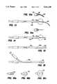
- FIG. 1is a schematic diagram of a preferred system showing use of an acoustic catheter according to the invention
- FIG. 1Ais a side view of the catheter driveshaft coil assembly.
- FIG. 2is a side view of a disposable catheter sheath for the acoustic catheter
- FIG. 3is a longitudinal, partially cut away view of the distal end of the rotating assembly of the acoustic catheter
- FIG. 4is a longitudinal, cross-sectional view of the distal end of the assembled acoustic catheter
- FIG. 5is a longitudinal sectional view of the transducer element of the catheter on a greatly magnified scale
- FIG. 6is a diagrammatic representation of sound waves emanating from the acoustic lens of the catheter.
- FIGS. 7 through 7dillustrate steps in filling the sheath and assembling the acoustic catheter of the figures, the syringe portions of the figures being on a reduced scale;
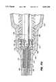
- FIG. 8is a cross-sectional view of the motor-connector assembly to which the catheter is connected while FIG. 8a is a view on an enlarged scale of a portion of FIG. 8;
- FIGS. 9, 10 and 11are graphical representations of torque in relation to angular deflection.
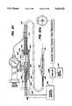
- FIG. 12is a block diagram of the electronic components useful with the acoustical catheter of the invention.
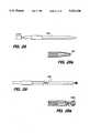
- FIGS. 13 and 13aillustrate an acoustic imaging catheter sheath having a distal floppy guide wire
- FIGS. 14 and 14aillustrate an acoustic imaging catheter sheath having a distal anchoring needle
- FIG. 15illustrates an acoustic imaging catheter sheath having a distal catheter extension beyond the transducer
- FIG. 16illustrates a combination balloon dilatation/acoustic imaging catheter sheath while FIGS. 16a, 16b and 16c illustrate stages of inflation of the balloon;
- FIG. 17is a view of a preferred embodiment of an acoustic imaging balloon angioplasty catheter.
- FIG. 17ais an expanded view of the distal end of the balloon catheter.
- FIGS. 17b and 17care partial cross sectional views taken along the lines AA in FIG. 17a; FIG. 17c is an expanded view of FIG. 17b.
- FIG. 17dis an expanded view of the proximal end of the catheter coupling, in partial cross-section.
- FIGS. 18-18eillustrate the use of an acoustic imaging balloon angioplasty catheter in a blood vessel.
- FIG. 19is a view of an alternative embodiment of an acoustic imaging dilatation balloon catheter.
- FIGS. 20-20bare views of alternative embodiments of an acoustic imaging dilatation balloon catheters enabling relative axial positioning of the transducer and the balloon.
- FIGS. 21-21bare views of alternative embodiments of an acoustic imaging balloon catheters, including multiple balloons.
- FIGS. 22 and 22aillustrate an acoustic catheter sheath adapted for guidance by a guide wire
- FIG. 23illustrates an acoustic catheter sheath which is deflectable by actuation from the proximal end
- FIGS. 24 and 24aillustrate an acoustic catheter sheath capable of injection of a fluid
- FIGS. 25 through 25cillustrate the combination of an acoustic catheter with a trocar
- FIG. 26illustrates an integrally formed acoustic catheter sheath
- FIG. 27illustrates an acoustic catheter sheath having an integral flexible distal extension
- FIGS. 28 and 28aillustrate a thin-walled acoustic catheter sheath residing under tension during use
- FIGS. 29 and 29aillustrate an acoustic catheter capable of driving a distal tool
- FIGS. 30 through 30cillustrate various positions of an acoustic imaging catheter during imaging of a heart valve
- FIG. 31illustrates an acoustic catheter sheath having an integrally formed acoustic window.
- a micro-acoustic imaging catheter 6is driven and monitored by a control system 8.
- the catheteris comprised of a disposable catheter sheath 12 (FIGS. 2 and 4) having a sound-transparent distal window 24 provided by dome element 25 (FIG. 4), in which is disposed a miniature, rotatable ultrasonic transducer 10 (FIGS. 3 and 4) driven by a special, high fidelity flexible drive shaft 18 (FIG. 1A).
- a relatively rigid connector 11is joined to the proximal end of the main body of the catheter sheath, adapted to be joined to a mating connector of drive and control system 8.
- the catheteris adapted to be positioned in the body by standard catheter procedures for example within a blood vessel or the heart by guiding the flexible catheter through various blood vessels along a circuitous path, starting, for example, by percutaneous introduction through an introducer sheath 13 disposed in a perforation of the femoral artery 15.
- disposable catheter sheath 12is a long tube, extruded from standard catheter materials, here nylon, e.g. with outer diameter, D, of 2 mm, wall thickness of 0.25 mm and length of 1 meter.
- catheter sheath 12 in its distal regionpreferably tapers down over region R as shown in FIG. 4 to a narrowed diameter D' at its distal end, achieved by controlled heating and drawing of this portion of the original tube from which the sheath is formed.
- Catheter sheath 12 and acoustically transparent dome element 25are adhesively bonded together.
- the drive shaft assembly 18is formed of a pair of closely wound multifilar coils 26; 28 wound in opposite helical directions. These coils are each formed of four circular cross-sectional wires, one of which, 30, is shown by shading. Coils 26, 28 are soldered together at both the distal and proximal ends of the assembly in interference contact, here under rotational prestress. By also providing a pitch angle of greater than about 20° a substantial part of the stress applied to the wire filaments of the coil is compression or tension in the direction of the axis of the filaments, with attendant reduction of bending tendencies that can affect fidelity of movement.
- the assemblyprovides such a torsionally stiff and accurate drive shaft that rotary position information for the distal end can, with considerable accuracy, be derived from measurement at the proximal end of the drive shaft, enabling high quality real-time images to be produced. (Further description of the coils of the drive shaft and their condition of operation is provided below.)
- Coaxial cable 32 within coils 26, 28has low power loss and comprises an outer insulator layer 34, a braided shield 36, a second insulator layer 38, and a center conductor 40.
- Shield 36 and center conductor 40are electrically connected by wires 42, 44 (FIG. 5) to piezoelectric crystal 46 and electrically conductive, acoustical backing 48 respectively, of the transducer.
- Transducer crystal 46is formed in known manner of one of a family of ceramic materials, such as barium titanates, lead zirconate titanates, lead metaniobates, and PVDFs, that is capable of transforming pressure distortions on its surface to electrical voltages and vice versa.
- Transducer assembly 10is further provided with an acoustic lens 52.
- the radius of curvature B of lens surface 52is greater than about 2.5 mm, chosen to provide focus over the range f (FIG. 6) between about 2 to 7 mm.
- the lensis positioned at an acute angle to the longitudinal axis of the catheter so that, during rotation, it scans a conical surface from the transducing tip, the angle preferably being between 10° and 80° e.g., 30°.
- Transducer backing 48is acoustically matched to the transducer element to improve axial resolution.
- the transducer assembly 10is supported at the distal end of the drive shaft by a tubular sleeve 29 which is telescopically received over a distal extension of the inner coil 28, as shown in FIG. 3.
- the length, E, of dome element 25is sufficient to provide headroom F for longitudinal movement of transducer 10 within the dome element as catheter sheath 12 and coils 26, 28 are twisted along the blood vessels of the body.
- transducer 10is a distance F, about 2 to 3 mm, from the internal end surface of the dome element 25.
- the dome element, along with catheter sheath 12is adapted to be filled with lubricating and sound-transmitting fluid.
- FIGS. 7-7bshow the filling procedure used to prepare ultrasound catheter sheath 12 (or any of the other interchangeable sheaths, see FIGS. 13-26) for attachment to the ultrasound imaging driveshaft and transducer assembly.
- a sterile, flexible filling tube 17 attached to a syringe 19is filled with sterile water.
- This filling catheteris inserted into the ultrasound catheter sheath 12, all the way to the distal tip. The water is then injected until it completely fills and the excess spills out of the ultrasound catheter while held in a vertical position, see FIG. 7a. This expels air from the catheter which could impair good acoustic imaging.
- a holding bracket 21is used to hold the catheter vertical during this procedure.
- the acoustic transducer 10 and shaft 18are inserted, displacing water from the sheath 12, until the installed position, FIG. 7d, is achieved.
- FIGS. 8 and 8ashow the interconnection arrangement for a connector 7 at proximal end of the acoustic catheter with connector 16 of the driving motor 20, and the path of the electric wires through the center shaft 43 of the driving motor.
- the center shaft and connector 16rotate together, as do the wires that pass through the hollow motor shaft.
- the latterconnect to a rotating electrical joint 27, which is held stationary at the back end and is connected to stationary coaxial cable 45 through a suitable connector such as a common BNC type.
- the enlarged viewshows how the motor connector 16 and the driveshaft connector 7 mate when the two assemblies are pushed together, thereby making both electrical and mechanical contact.
- the catheter connector 7is held in position by an ordinary ball bearing which provides a thrusting surface for the rotating connector 16 and driveshaft 18 while allowing free rotation.
- the disposable catheter sheath 12includes an inexpensive, relatively rigid hollow bushing 11 of cylindrical construction that allows it to be slid into and held by means of a set screw in the housing that captures the non-disposable bearing, connector, and driveshaft 18.
- the transducer 10is electrically connected by coaxial cable 32 extending through coil assembly 18 and via the cable through the motor to the proximal electronic components 22 which send, receive and interpret signals from the transducer.
- Components 22include a cathode ray tube 23, electronic controls for the rotary repetition rate, and standard ultrasonic imaging equipment; see FIG. 12.
- a rotation detectorin the form of a shaft encoder shown diagrammatically at 19, detects the instantaneous rotational position of this proximal rotating assembly and applies that positional information to components 22, e.g., for use in producing the scan image.
- coils 26, 28are each manufactured by winding four round cross-section stainless steel wires of size about 0.2 mm, so that D o is about 1.3 mm, D i is about 0.9 mm, d o is about 0.9 mm and d i is about 0.5 mm.
- the coilsare closely wound with a pitch angle ⁇ o and ⁇ i where ⁇ o is smaller than ⁇ i , e.g., 221/2° and 31°, respectively.
- Frat wires having a cross-sectional depth of about 0.1 mmmay also be used.
- the pitch anglesare chosen to eliminate clearances 60 between the wires and to apply a substantial part of the stress in either tension or compression along the axis of the wire filaments.
- the coils, connected at their ends,are adapted to be turned in the direction tending to make outer coil 26 smaller in diameter, and inner coil 28 larger.
- the two assembliesinterfere with each other and the torsional stiffness constant in this rotational direction is significantly increased (by a factor of about 6) due to the interference.
- Operation of the driveshaft in the torsionally stiff region with enhanced fidelityis found to be obtainable by adding a torsional load to the distal end of the rotating assembly of the catheter. The importance of rotational fidelity and details of how it is achieved warrant further discussion.
- position informationis not measured at the distal tip of the catheter, but rather from the drive shaft at the proximal end, only with a torsionally stiff and true drive shaft can accurate position information and display be obtained.
- any drive shaft within a catheter sheathwill have a particular angular position which is naturally preferred as a result of small asymmetries. Due to this favored position, the shaft tends, during a revolution, to store and then release rotational energy, causing non uniform rotational velocity. This phenomenon is referred to as “mechanical noise” and its effect is referred to as “resultant angular infidelity” for the balance of this explanation.
- TSCtorsional spring constant
- inner coil 28four individual wires are simultaneously wound around a mandrel of about 0.5 mm outer diameter. The free ends of this coil are fixed, and then four wires are wound in opposite hand directly over this coil to form the outer coil 26.
- the wiresare wound under moderate tension, of about 22.5 gm/wire. After winding, the coils are released.
- the inner mandrelwhich may be tapered or stepped, or have a constant cross-sectional diameter, is then removed.
- the wire endsare finished by grinding.
- One endis then soldered or epoxied to fix the coils together for a distance of less than 3 mm. This end is held in a rigid support and the coils are then twisted sufficiently, e.g. 1/4 turn, to cause the outer coil to compress and the inner coil to expand, causing the coils to interfere.
- the free endsare then also fixed.
- the coil assembly 18is generally formed from wires which provide a low spring index, that is, the radius of the outer coil 26 must be not more than about 2.5 to 10 times the diameter of the wires used in its construction. With a higher index, the inner coil may collapse.
- the multifilar nature of the coilsenables a smaller diameter coil to be employed, which is of particular importance for vascular catheters and other catheters where small size is important.
- coaxial cable 32is inserted within the inner coil.
- the cablemay be silver-coated on braid 36 to enhance electrical transmission properties. It is also possible to use the inner and outer coils 26, 28 as one of the electrical conductors of this cable, e.g. by silver coating the coils.
- wire 42is soldered to either side of electrically conducting sleeve 29 formed of stainless steel.
- Wire 44is inserted into a sound absorbent backing 48 which is insulated from sleeve 29 by insulator 72.
- Piezoelectric element 46of thickness about 0.1 mm is fixed to backing 48 by adhesive and electrical connection 74 is provided between its surface and the end of sleeve 29.
- wire 42is electrically connected to the outer face of piezoelectric element 46, and wire 44 electrically connected to its inner face.
- Spherical lens 52formed of acoustic lens materials is fixed to the outer surface of element 46.
- the completed drive shaft 18 and transducer 10are inserted into disposable catheter sheath 12, positioning transducer 10 within acoustically transparent dome element 25, with liquid filling the internal open spaces.
- the catheter thus preparedis ready to be driven by the drive assembly; see FIG. 8.
- a preferred acoustic catheteris constructed so that it may be preformed prior to use by standard methods.
- the cathetercan be appropriately shaped prior to insertion.
- Such preformationcan include bends of about 1 cm radius and still permit satisfactory operation of the drive shaft.
- FIG. 12is a block diagram of the electronics of a basic analog ultrasound imaging system used with the acoustical catheter.
- the motor controller (D)positions the transducer B for the next scan line.
- the transmit pulser (A)drives the ultrasound transducer.
- the transducer (B)converts the electrical energy into acoustic energy and emits a sound wave. The sound wave reflects off various interfaces in the region of interest and a portion returns to the transducer.
- the transducerconverts the acoustic energy back into electrical energy.
- the receiver (C)takes this waveform and gates out the transmit pulse.
- the remaining informationis processed so that signal amplitude is converted to intensity and time from the transmit pulse is translated to distance.
- This brightness and distance informationis fed into a vector generator/scan converter (E) which along with the position information from the motor controller converts the polar coordinates to rectangular coordinates for a standard raster monitor (F). This process is repeated many thousands of times per second.
- the acoustical imaging cathetermay be introduced by standard techniques, preferably by percutaneous insertion, into any desired blood vessel. Alternatively, it can be introduced directly into a body cavity or body tissue such as an organ. Due to its rotational fidelity, the device provides a relatively high quality, real time image of blood vessel tissue and allows ready diagnosis of disease states such as occlusion or dyskinesia. The acoustic properties of various tissues can also be discerned to allow more accurate diagnosis. It is also possible to form 3-dimensional images using appropriate computer software and by moving the catheter within the blood vessel. The device is also useful in angioplasty therapy to determine the nature and geometry of intravascular protrusions.
- This devicemay be combined with existing optical devices to provide a device having an ultrasonic visualizing probe and a laser ablating ability.
- the devicemay also be used in diagnosis of, e.g., esophageal tumors or prostate carcinomas, by passing the catheter through the anus, urethra, trachea, or esophagus.
- the catheteris also useful for valvuloplasty by insertion through a cardiac valve. Further, in non-medical areas, the device is useful for any inaccessible passages which are fluid filled, and thus transmit sound waves.
- a wide variety of novel disposable catheter sheathscan be substituted for catheter sheath 12 and used in the system.
- FIGS. 13 and 13ashow a flexible, disposable catheter sheath 12a that is constructed like sheath 12 and has, in addition at its distal tip, a floppy guide wire 80 which is useful for guiding the ultrasound device through a valve such as of the heart.
- the guide wireis constructed of a closely wound wire coil 82 and an internal safety wire 84 for added strength.
- Wire 84is welded to the distal tip of coil wire 82 and its proximal end is bent over within dome 24 and securely anchored with epoxy cement.
- the safety wireextends through a separate lumen of the catheter sheath to a securing point at the proximal end of the catheter.
- coil 80is useful in supporting and steadying the free end of the ultrasound device during axial movement of the catheter to improve its imaging capability; see FIGS. 30-30c.
- FIG. 14shows sheath 12b having needle 86 securely anchored to the tip, useful for impaling a surface, such as that found in the interior of the heart, and temporarily anchoring and steadying the ultrasound device in a fixed position.
- ittoo can have a safety wire extending to a proximal securing point.
- This acoustic cathetermay be introduced through an introducing catheter.
- the needlecan be retracted during introduction.
- FIG. 15shows another flexible, disposable sheath 12c that is constructed so that the sonolucent (acoustically transparent) portion 24a is spaced from the distal end instead of at the end.
- the extension 12x beyond the window 24amay be of the same flexible catheter material as the main body of the sheath or of a different, e.g. softer material, and may be either open, so that fluids may pass through it, or closed, so that no fluids pass through.
- the distal extension of the catheter sheathcan serve to stabilize the lateral position of the transducer during axial movement of the catheter during imaging.
- FIG. 16shows a catheter sheath 12d on which is mounted, over the transducer area, a dilatation balloon 55 such as is commonly used for angioplasty.
- the balloonis adapted to be pressurized with liquid, such as water, through the same lumen that holds the ultrasound imaging device, via an inflation opening in the wall of the catheter sheath.
- This catheteris used to open a clogged, stenotic or narrowed passage in the body, while simultaneously measuring the progress of the dilatation procedure with the ultrasound images.
- Another embodiment with a suitable balloonmay be used to center or position the ultrasound device securely within a body passage or cavity and maintain its position away from a feature of interest, for instance for imaging a wall of the heart.
- the balloon in its collapsed or unpressurized stateis easily inserted prior to positioning and may be accurately positioned by use of ultrasound imaging during initial placement.
- a separate lumenis provided for inflation of the balloon and/or the balloon is spaced from the distal end of the catheter.
- the system 120includes a boot member 122 including a ferrule member 124 at its proximal end, constructed to enable electrical and mechanical connection, as discussed for example with respect to FIGS. 8-8a, to the acoustic imaging control system, as discussed for example with respect to FIG. 1, for transmitting rotary power and control signals to the acoustic imaging transducer held within the balloon catheter sheath 139 near balloon 140 and for receiving acoustical image signals from the transducer to enable monitoring and control of the dilatation process, as will be further described below.
- the proximal end of the apparatusfurther includes a seal 126 (FIG. 17d) which enables intimate but relatively frictionless contact with the portion of the rotating drive shaft, and will also be further discussed below.
- the catheter apparatusmay be sized for use in various body cavities and applications such as the coronary arteries, peripheral arteries such as the iliac and femoral artery, the extremities, the esophagus, prostate and for valvuloplasty.
- peripheral arteriessuch as the iliac and femoral artery
- the extremitiesthe esophagus
- prostateand for valvuloplasty.
- a 6 F sheath 128extends a distance of L 1 , about 30 cm from the end of the seal 126 to a "Y" double flare compression fitting 130.
- Fitting 130includes a side arm 132 for introduction of inflation fluid such as water or saline by means of a screw syringe 134 for inflation of balloon 140 near the distal end of the catheter 139.
- the side arm 130further includes inner passageways for control wires (not shown) within the balloon for controlling a heating means enabling heating of the inflation fluid for the purpose of heated balloon angioplasty.
- the heater control wiresmay be passed, for example, through conduit 136 to heater control module 138.
- catheter body sheath 139Extending distally from the compression fitting 130 is catheter body sheath 139 which has an outer diameter of 4.8 F and extends a distance L 2 about 92.5 cm to the center of the balloon 140.
- the cathetermay be adapted to track a guidewire 152 which passes through a sonolucent saddle member 159 beneath the balloon and out of a distal extension 157 of the catheter, distal to the balloon.
- septum tip 142Also distal to the balloon is self-sealing septum tip 142 enabling introduction of saline or another fluid for purging the balloon of air bubbles that might impair acoustic imaging.
- Such a self-sealing septumis described in U.S. Pat. No. 5,002,059, the entire contents of which are hereby incorporated by reference.
- the length of the system 120, from the end of the ferrule to the center of the balloonis L 3 , about 132.5 cm and the length from the seal 126 to the center of the balloon is L 4 , about 127.7 cm.
- the catheter 139extends distally from the center of the balloon a distance L 5 , about 3 cm.
- the balloon length, L 6is about 4 cm (inflated diameter about 7-8 mm).
- the extension 157 distal to the balloonis L 7 , about 1.5 cm.
- the catheter lengthis L 8 about 95 cm.
- FIG. 17athe distal end of the catheter is shown in partial cross section with the balloon deflated and inflated (phantom).
- a rotating ultrasound transducer 146 having a coil form drive shaft 141is positioned on the central axis A of the catheter sheath 139 at a position corresponding to the inflatable dilatation balloon 140.
- the catheter sheath 139forms a sonolucent guide for the transducer 146 and drive shaft.
- the catheter sheathis formed of a thin (0.005 to 0.007 inch) sonolucent material such as polyethylene to provide sufficient guidance for the drive shaft and transducer without causing excessive attenuation of the ultrasound signal emitted by the transducer.
- the catheter body material, the balloon material, and the guidewire saddleare in general selected to be sonolucent and have an acoustic impedance substantially matched to the body fluid, e.g., blood, to which the catheter is exposed, to minimize attenuation of the acoustic signals emitted and received from the transducer.
- Polyethyleneis advantageous in that it has an acoustic impedance that substantially matches blood and saline, it is capable of withstanding high dilatation pressures and is only slightly elastic, enabling a reliable balloon inflation diameter.
- An advantage of the present systemwhich allows observation of balloon inflation during dilatation, is that balloon materials with some elasticity may be employed without danger of over-inflation within a lumen since the operator can suspend inflation in response to the acoustic image at any time during treatment.
- the cathetermay be formed having sonolucent regions corresponding to the location of the transducer while the rest of the catheter is not sonolucent, e.g., made of thicker material.
- Fluid communication between the balloon and the catheteris provided through port 151 to equalize the fluid pressure encountered during dilatation between the balloon and within the catheter to reduce the risk of collapse of the typically thin, sonolucent catheter and subsequent undesirable binding of the driving shaft which rotates the transducer, when the balloon is inflated at relatively high pressures, e.g., over 100 psi for balloon angioplasty procedures.
- the dilatation balloon 140which is preferably polyethylene, as discussed, may be mounted at its ends 147, 148 over the guidewire saddle by, for example, melt-sealing.
- the balloonmay also be secured to the saddle by clips or the like as conventionally known.
- the catheterPrior to mounting the balloon in this area, the catheter is fitted with the sonolucent saddle 159 that extends under the area of the balloon and exits distally and proximally beyond the ends of the balloon.
- the saddleenables the use of a thin walled single lumen catheter body that is substantially sonolucent. Further, the use of single lumen catheters enables smaller catheter sizes to be employed, for example, 3F catheters which can be used in coronary arteries.
- the saddle guideas shown in cross section in FIG.
- the saddle 17b(taken along line A--A of FIG. 17a) and in FIG. 17c is a tubular member disposed over the catheter having a bowed or stretched portion that creates a lumen in which the guidewire is placed.
- the saddle inner lumenis of sufficient clearance to allow the catheter to track over a guide wire.
- the saddle ends 154, 155are angle cut and smooth edged to allow ease of entry of and guidance by the guide wire 152.
- the saddleis preferably formed of polyethylene having a wall thickness, T 1 , of about 0.004 inch.
- the thickness of the catheter body wallis T 2 , is about 0.007 inch.
- the guidewire diameteris D 1 about 0.018 inch and the drive shaft is of a diameter D 2 of about 0.045 inch.
- the guide wirepasses through a side aperture 153 in the extension 157 of the catheter 139 distal to the balloon, through the inner lumen of the extension 157 and a distal aperture 161.
- the guidewireis exposed to the body lumen except for its passage through the saddle and distal extension of the catheter.
- the saddlemay be, for example, disposed around the entire circumference of the catheter along a continuous length of the catheter corresponding to the length of the balloon in which case a port at a location corresponding to the port 151 must be provided in the saddle, or optionally, the saddle may be disposed around the entire circumference of the catheter only at its proximal and distal ends, and partially about the circumference therebetween, enabling free flow from port 151.
- the distal tip of the catheteris fitted with self-sealing septum 158 to allow introduction of saline or the fluid distally, forcing air bubbles that might impair acoustic imaging and successful balloon inflation proximally.
- the septummay be used as an air vent when a needle is inserted, allowing the catheter to be filled with fluid from a side arm, in which case bubbles and undesirable air may be expelled efficiently and completely.
- the septumis more completely described in U.S. Pat. No. 5,002,059, incorporated supra.
- annular electrical contacts 143, 144 inside of balloon 140are bonded directly to the catheter sheath 139.
- the contactsare positioned on either side of the transducer 146 and are spaced apart approximately half the length of the balloon. The spacing from the respective ends of the balloon is approximately one fourth the length of the balloon, so that the balloon will heat evenly.
- the contacts 143 and 144connect to opposite poles of current-controlled (constant current) radiofrequency power supply in the control module 138.
- the catheteralso includes a thermistor 145, located just proximally of the transducer 146 for measurements of balloon temperature.
- Wires for the contacts and thermistorare enclosed within catheter sheath 139 along its length, and exit catheter through a lumen, which is accessible from inside of balloon 140.
- the wiresmay also be provided in a separate lumen in a two-lumen guide catheter.
- the control moduleincludes an RF power supply that preferably operates at 650 kilohertz, but can be at any frequency within the range of about 100 kilohertz to 1 megahertz.
- the inflation fluidwhile selected to have resistive losses, has an electrical impedance low enough that it will conduct the current supplied by RF power supply at voltages of about 100 volts or lower, so that there will be no arcing.
- a full description of a suitable RF heated balloon systemis described in U.S. application Ser. Nos. 07/404,483 filed Sep. 8, 1989 and 263,815 filed Oct. 28, 1988 (now U.S. Pat. No. 4,955,377), the entire contents of both said applications being incorporated herein by reference. Furthermore, it will be understood that other methods for balloon heating may be employed.
- the catheteris provided with a stationary pressure tight shaft seal 126 that fits in intimate, but relatively frictionless contact with a portion of the rotating drive shaft 162.
- the sealincludes a ball seal 170 (available from Bal-seal Engineering Company, Inc., Santa Anna, Calif.), securely held in place by a seal holder 172 (stainless steel or elastomer), which abuts the distal end of the internal open area of the boot 122 and is held by compression of the ferrule assembly 164 (although other means of attachment such as injection molding are possible).
- the seal holder 172includes a retainer sleeve 174 that extends coaxially with respect to the catheter 139.
- the drive shaftis held within a gland 178, preferably formed from hypotubing, which makes relatively frictionless contact with the ball seal 170, enabling rotation while preventing back flow of inflation fluid into the ferrule.
- the ball sealis an annular U-shaped member, including within the U a canted coil spring 179 (such that the axis of each coil is tangent to the annulus) that presses the legs 175, 177 of the seal radially.
- the outer leg 175 of the sealengages an extension 176 of the seal holder, while the inner leg 177 of the seal engages the gland 178.
- the bootalso includes a thin (few thousands of an inch) metal sleeve 171 for additional sealing around the catheter.
- the drive shaft 162is modified in the sealing area 168 by impregnating it with a thermoplastic material that fills the gaps in the individual wires to prevent flow of inflation fluid through the drive shaft inner lumen at typical inflation pressures of 100-120 psi or higher.
- the drive shaftmay be sealed by impregnating it with a liquid that is hardenable, such as epoxy, and then covering that area with a section of cylindrical metal, such as hypotube, in order to form a smooth, fluid tight seal capable of holding up to typical balloon pressure.
- a liquid that is hardenablesuch as epoxy
- a section of cylindrical metalsuch as hypotube
- other sealing membersmay be used, e.g. an O-ring.
- Preparation of the deviceis accomplished by the following steps: A Leveen inflator is connected to the side arm. The side arm valve is opened and air is evacuated by suction. (Generally, the balloon contracts in a folded manner which leaves air passages through the interior of the balloon and prevents blockage of the passageway 151.) A hypodermic syringe fitted with a small gauge needle and filled with a fluid such as water or saline is then inserted through the distal tip septum seal. Fluid is introduced until surplus exits the side arm, at which point the valve is closed, reducing the chances that air will re-enter the catheter. Alternately, the fluid may be introduced via the side arm when an air venting needle is inserted into the distal septum.
- the catheteris then attached to the driving motor, (not shown), by mating the ferrule 124 with a mateable receptacle which connects the ultrasound imaging electronics. Imaging can begin as soon as the deflated balloon is inserted into a subject lumen. Because the balloon material, saddle and sonolucent guide effectively transmit ultrasound energy, continuous imaging and monitoring of the subject lumen can be achieved.
- the devicemay be used to view the lumen and stenoses for diagnostic purposes, then the balloon may be positioned accurately in any portion of the lumen such as a stenoses, and dilatation of the stenotic area may be performed using conventional dilatation technique while the progress of treatment is monitored by ultrasonic imaging and treatment is modified in response to the observed response of the tissue. Finally, after treatment, the balloon may be deflated and the lumen imaged to observe the treated site or view other sites.
- the modular constructionenables the ultrasound imaging catheter's ability to be slidably inserted into a number of different types and styles of catheter sheaths.
- the pressure and fluid tight connector that is mounted distally to the location of the side arm connectorenables various catheters, such as those with balloons of different sizes, to be effectively attached at the location of the side arm connector.
- the acoustic imaging balloon cathetermay be used to apply pressure (and optionally, heat) to dilate a blood vessel by molding the wall or an obstructing material (like plaque).
- the blood vesselmay be a coronary artery, or a peripheral artery such as an iliac, femoral, renal, carotid, or popliteal artery.
- the balloon cathetermay also be useful for dilatations in the biliary tract, esophagus or prostate.
- a percutaneous insertionis made with a needle, and a guidewire is introduced into the blood vessel 112.
- the acoustic imaging balloon catheter 110follows the wire (for example employing the saddle arrangement discussed above) and is positioned at an obstruction in the artery such as a plaque deposit 114 (FIG. 18) by visualizing the inner walls of the artery by acoustic imaging as the catheter is advanced.
- the balloon 116is inflated to engage the plaque material 114 forming the obstruction (FIG. 18a).
- the operatorviews the progress of the dilatation to assure that the dilatation does not occur too rapidly, which may lead to the formation of cracks or flaps which may in turn lead to re-occlusion.
- the pressure in the balloonmay be kept below the normal pressure required under ambient conditions to widen the vessel to avoid cracking the plaque.
- Normal dilation pressuremeans the minimum pressure at which an unheated balloon causes substantial dilation of the respective lumen.
- the low, subdilatation pressure used initially to engage the plaque materialmay be, for example, about two atmospheres.
- normal dilation pressureis of the order of 5 to 10 atmospheres (varies with balloon size).
- the balloonself-forms around the irregular surfaces of the obstruction and provides a firm contact for efficient and even transfer of heat. As the occlusion yields (by virtue of heating and gentle pressure as described below), the balloon expands to maintain even contact with the surface.
- the operatormonitors the dilatation by acoustic imaging to determine various physiological conditions and responses to treatment.
- the usermay initiate the bi-polar heating between the electrodes 143, 144 as discussed above, (e.g. by depressing a footswitch to start a heating program).
- the heat from the fluidis conducted across the balloon wall into the surrounding tissue 44.
- the fluidwill heat to the temperature set by the user to carry out a temperature algorithm.
- the temperature at the balloon surfaceranges from 45°-90° C. and is typically from 50° to 70° C., sometimes preferably, around 60°-65° C.
- the operatormonitors the condition and physiological response of the vessel under treatment by acoustic imaging.
- the heterogeneous plaque materialusually including fat, fibrogen, calcium
- softensresulting in a change in the allowable volume of the balloon at a given low pressure (preferably below the pressure needed to crack the obstruction).
- the stenosesis observed by acoustic imaging to expand slowly as the occluding material elastically (reversibly) expands with gentle heating until, upon reaching a yield point at time corresponding to the conditions of pressure and temperature at which the occlusion yields. Thereafter, the stenoses is observed by acoustic imaging to yield at a higher rate as the occluding material yields plastically (substantially nonreversibly).
- the operatordetermines the course of further treatment, which may include maintaining or slight changes in temperature or pressure of the balloon, to effect full dilatation of the artery where the continued treatment leads to full expansion of the balloon and artery at a time.
- the temperature of the balloonis reduced, while the balloon remains inflated. Recycling the temperature allows the material of the obstruction, the plaque, to be mold-formed by the balloon as it cools and reconstitutes. The interior walls of the remodeled lumen are left smooth and with reduced chance of re-occlusion. The temperature is reduced while the balloon is inflated.
- the balloonis deflated and removed from the body lumen.
- the operatorthen can observe the dilated vessel by acoustic imaging.
- the transducer 146is positioned in the distal tip extension of the balloon catheter and distal to the balloon.
- a sonolucent window located distal to the balloonallows imaging to take place during the positioning of the balloon and after treatment.
- ultrasonic energyis not transmitted through the catheter sheath 190, balloon 191 or saddle 192 as in the previously mentioned embodiments.
- the catheteris advanced a known amount, e.g. a few centimeters, (monitorable from outside the body) and the balloon is inflated. The dilatation is performed, and then the balloon is withdrawn, allowing a post dilatation view of the region.
- the transducermay be positioned proximal to the balloon. These embodiments may be particularly useful for prostate dilatation where the balloon is to be positioned distal to the urinary sphincter to avoid dilation of the sphincter. By visualizing the sphincter by acoustic imaging with a transducer proximal to the balloon, the operator is assured that the balloon is distal to the sphincter.
- FIGS. 20-20bother embodiments of the acoustic imaging catheter device allow relative movement of the transducer and balloon so that the ultrasound transducer may be positioned in any longitudinal position in the balloon, or distal or proximal to the balloon, for an assessment, inspection of the body lumen and monitoring of the placement of the balloon, the dilatation procedure and then post-treatment inspection.
- the drive shaft and transducer 146may be slid axially as indicated by arrows 195 to move the transducer, for example, continuously to positions between position I, proximal to the balloon and position II, distal to the balloon.
- a slide assembly 240is provided including a housing 244 having a distal end which receives the catheter sheath 139 and drive shaft 145.
- the drive shaftcontacts a pair of oppositely arranged, relatively frictionless ball seals 245, 246 press fit within the housing against an inner body extension 249 and the distal end member 248 of the body which is threaded into the body 244.
- the ball sealsengage a gland 250 as discussed with respect to FIG. 17d.
- the glandis attached to a thumb control 252, provided within the body to enable axial motion of the drive shaft to position the transducer within the catheter corresponding to regions within the balloon and in the distal extension, both of which are sonolucent.
- the transducer 146it may be advantageous, as illustrated by the position of the transducer 146 in the series of FIGS. 18-18e, to position the transducer in the distal extension of the catheter during insertion of the catheter to inspect and locate the region to be treated by the balloon, then retract the transducer into a region corresponding to the balloon to observe dilatation and finally, the transducer may be slid forward for post treatment inspection of the lumen after balloon deflation.
- the axially translatable transducer devicefurther includes a carbon resistor 254 within the slide assembly housing, and contact means 258 attached to the thumb control and in contact with the resistor.
- Probe wires 256, 257are connected to the resistor 254 and contact means 258 to provide variable resistance between the probe wires as the thumb control is slid axially, which is detected at detector 260, to provide monitoring of the axial position of the transducer.
- the thumb controlmay be hand actuated or controlled by automatic translator means 264 which receives control signals from a controller 266.
- the output from the detector 260is provided to an analysis means 268 which also receives the acoustic images from the transducer corresponding to various axial positions of the transducer within the catheter body to provide registry of the images with the axial transducer position on a screen 270.
- the transduceris slid axially, along a continuous length or at selected positions of the catheter body, for example, from the balloon to the distal tip, and the analysis means includes storage means for storing images along the length to reconstruct a three-dimensional image of the lumen along the axial length of transducer travel.
- FIG. 20bshows an embodiment wherein the catheter includes a bellows member 280 to enable axial motion of the catheter body with respect to the transducer.
- the balloonis asymmetrical, either or both in shape and expansion capability, and is mounted on a catheter shaft that is torquable, and can then be positioned using acoustic imaging so that radially selective dilatation is accomplished on the desired portion of the lumen wall by torquing the catheter.
- the positioning, rupturing, stretching and compression of the lesion and surrounding tissue, and the deflation of the ballooncan all be monitored with cross-sectional ultrasonic images.
- a balloon catheter 200comprises a catheter shaft 202 and at least two balloons 204 and 206.
- Catheter shaft 200passes through the length of balloon 204.
- the proximal and distal ends of balloon 204are tacked onto catheter shaft 202 at locations adjacent the proximal and distal ends of balloon 204.
- Catheter shaft 202includes inflation and pressure equalization ports 207, 208 within balloon 204 through which fluid enters and exits balloon 204, and ports 210 and 212 through which fluid enters and exits balloon 206.
- each of the balloons 206 and 208when inflated, typically ranges from 2 millimeters for vascular procedures to 20 to 35 millimeters for hyperthermia treatment of the prostate, esophagus or colon.
- the combined volume of the balloonsranges from 1/8 cc for the smallest balloons to 100 cc for the largest balloons.
- the wall thickness of the balloons 204 and 206is about 0.001 inch.
- a guidewire 214which can extend past the distal end of the catheter, may be used to guide the catheter through the vascular system or other luminal structures.
- the guidewiremay also be passed through a saddle as discussed above, for example, with respect to FIG. 17a.
- the exteriors of the balloonsare coated with a non-stick coating having a low coefficient or friction, such as silicone or polysiloxane.
- the non-heated balloonmay be covered with a coat of heat-insulating material or silver heat-reflective material thereby enhancing the temperature difference between the heated balloon and the unheated balloon.
- Balloons 204, 206are fillable with an electrically conductive fluid such as normal saline (0.9 percent NaCl in water), a conductive radiopaque fluid, or a mixture of saline solution and a radiopaque fluid.
- an electrically conductive fluidsuch as normal saline (0.9 percent NaCl in water), a conductive radiopaque fluid, or a mixture of saline solution and a radiopaque fluid.
- balloons 204 and 206may be replaced by a single, multi-segmented balloon.
- Catheter shaft 202passes through the length of one of the segments. The other segment connects with catheter shaft 10 at the locations of lumens 210 and 212.
- Electrodes 218 and 220which effect heating by RF power dissipation, as discussed above are exposed to the fluid inside of one of the balloons 204, but are not substantially exposed to the fluid inside of the other balloon 206.
- a coil-form drive shaft 222(phantom) having at its distal portion an acoustic transducer 224.
- the shaftis rotatable, enabling acoustic imaging of the lumen to be treated for positioning of the catheter and balloons, monitoring treatment and post-treatment inspection of the lumen.
- the multiple balloon catheteris shown in cross-section along line B--B of FIG. 21.
- the catheter 202includes a single lumen 230 which rotatably supports the drive shaft 222 as discussed above. Inflation fluid for both balloons is passed through the lumen 230 and the inflation ports 207, 208, 210 and 212 as described above.
- the location of the heater contacts 218, 220 in balloon 206results in substantial heating of balloon 204, with only minor conduction of heat and RF power through the catheter body to balloon 206. Further details of a multiple balloon catheter adaptable to acoustic imaging are discussed in U.S. Pat. No. 5,151,180.
- FIGS. 25 and 25ashow sheath 12e, similar to sheath 12, which is additionally fitted with an eyelet 90 through a solid portion of the tip to allow the free passage of a guide wire 92 which is used to help guide the catheter to a region of interest inside a passage of the body.
- FIG. 23shows sheath 12f having a two lumen construction.
- the large lumencontains the transducer and drive shaft while the small lumen contains a wire 94.
- wire 94is a deflecting wire attached near the distal end, and is free to slide through its lumen under tension applied to ring 96 to cause the catheter to bend when pulled taut, thus providing a measure of control of the orientation of the distal end of the acoustic catheter while negotiating the passages of the body or the like.
- wire 94may be a preformed stylet, which, when inserted through the second lumen, causes deflection of the tip.
- FIG. 24shows sheath 12g having a small hole 97 at its distal end to allow the passage of a fluid under pressure, such as saline or clot dissolving enzyme such as urokinase, or radiographic contrast enhancement fluids.
- a fluid under pressuresuch as saline or clot dissolving enzyme such as urokinase, or radiographic contrast enhancement fluids.
- FIG. 25shows sheath 12h placed in a specially designed hollow, rigid, sharply pointed metallic trocar 98 similar to a lance, designed to be driven into the body and further into the tissue of an organ of interest, such as the liver or spleen, to provide ultrasound imaging of an area where there is no natural passageway.
- a side-facing window 99 in the distal region of the trocar tubeallows the passage of ultrasound energy from and to the transducer to enable imaging to take place.
- a portion of the trocar(phantom, FIG. 25a) may be formed of sonolucent material, to form an ultrasonic window.
- the hollow trocar tubeserves further to prevent crushing or deformation of the ultrasound catheter under the considerable pressure required to drive the device into solid body tissue. After ultrasound inspection the imaging catheter may be withdrawn from this device and a biopsy device may then be inserted in its place with the advantage that the region from which the biopsy is to be taken has been very accurately located by acoustic imaging.
- the acoustic imaging-trocar apparatusis useful, for example for diagnosis of tumors in the liver.
- liver canceris first evidenced by a number of very small tumors that are diffuse and randomly located making them difficult to visualize by external ultrasound apparatus.
- early detection of cancerous tumorsmay be accomplished by driving the ultrasound catheter inside the trocar into the liver where small tumors are suspected or likely to be.
- driving the catheter into the tissuealthough there is no natural passageway, the operator can search for tumors in the field of view.
- the operatorcan remove the ultrasound imaging catheter and place within the trocar a biopsy sampling instrument such as forceps 284 to collect a small portion of the tumor (FIG. 25b).
- the forceps jaws 283, 285are moveable from proximal portions as indicated by arrows 287 to open and close the instrument to grasp a sample. Similar procedures may be carried out in the breast, in searching for small tumors. In general the benign tumors are more or less encapsulated whereas cancerous tumors have a diffuse edge therefore enabling a preliminary analysis of the tumor by acoustic imaging.
- the trocarmay include at its distal end, in the vicinity of the transducer a radioactive pellet 286, for radiation treatment of tumors found by ultrasonic imaging.
- FIG. 26shows flexible, disposable sheath 12i made of integral, thin-walled extruded plastic which is more or less sonolucent. This construction avoids the necessity of having a separate dome or window attached to the distal end.
- the distal endis post formed (thinned, e.g. by drawing and blowing) after extrusion to provide the correct wall thickness dimension for best sonic transmission and mechanical strength and may be sealed fluid tight at the tip.
- FIG. 27shows sheath 12j which is similar to sheath 12i of FIG. 26, and additionally has an integral floppy tip made by continuing the drawing process to form a small diameter solid but flexible extension of the sheath beyond the sonolucent area; it can achieve certain of the advantages of catheter 12a of FIG. 13 but without the additional cost of adding a separate metal floppy guide wire.
- FIG. 28shows sheath 12k which is formed to have an inner end bearing surface 101 at the distal tip for serving as an axial and radial bearing for the rotating ultrasound transducer.
- This bearingis e.g. a small spherical or conical formation.
- FIGS. 29 and 29ashow sheath 12l which is fitted with a keyed rotating shaft that accepts the end of a similarly keyed ultrasound transducer, and acts as a power takeoff for driving a rotatable instrument such as the atherectomy cutter 105, shown.
- FIGS. 30-30cshow a sheath constructed along the lines of sheath 12a of FIG. 13, being used in guiding and penetrating through the moving opening of a human heart valve. It shows how the floppy guiding wire acts as a stabilizer and a centering device allowing the ultrasound device to be moved forward and withdrawn repeatedly and consistently, as is desirable for proper imaging of the valve before and after valvuloplasty.
- FIG. 31shows an integrally-formed catheter sheath having an acoustic window 24i originally of the same extruded material as the body of the catheter, the material of the window being modified to enhance its acoustic window properties.
- the main body 12 mb of the sheathhas wall thickness t of 0.4 mm and outer diameter D of 2 mm.
- the integral window 24 ihas outer diameter D corresponding to that of the main body of the catheter and a modified wall thickness t 1 of 0.2 mm.
- any of these cathetersmay be additionally fitted with radiopaque markers either at the tip or the middle or both, designed to be visible when seen under the fluoroscope while intraluminal ultrasound imaging takes place.
- the markersare made of a metallic material that blocks X-ray radiation or a metal filled adhesive or epoxy is applied to the surface, in a groove, or at the end of the device. Additionally the metal-filled epoxy may be used to seal the end of the device as well as provide radiopacity.
Landscapes
- Health & Medical Sciences (AREA)
- Life Sciences & Earth Sciences (AREA)
- Engineering & Computer Science (AREA)
- Surgery (AREA)
- Biomedical Technology (AREA)
- Physics & Mathematics (AREA)
- Veterinary Medicine (AREA)
- Heart & Thoracic Surgery (AREA)
- Medical Informatics (AREA)
- Molecular Biology (AREA)
- Animal Behavior & Ethology (AREA)
- General Health & Medical Sciences (AREA)
- Public Health (AREA)
- Pathology (AREA)
- Biophysics (AREA)
- Nuclear Medicine, Radiotherapy & Molecular Imaging (AREA)
- Radiology & Medical Imaging (AREA)
- Immunology (AREA)
- Vascular Medicine (AREA)
- Cardiology (AREA)
- Plasma & Fusion (AREA)
- Otolaryngology (AREA)
- Ultra Sonic Daignosis Equipment (AREA)
- Media Introduction/Drainage Providing Device (AREA)
Abstract
Description
This is a continuation of U.S. application Ser. No. 07/570,319, filed Aug. 21, 1990, now abandoned, which is a continuation-in-part of Ser. No. 07/171,039, filed Mar. 21, 1988, and now U.S. Pat. No. 4,951,677 by Robert Crowley et al. and entitled: "Acoustic Imaging Catheter and the Like".
This invention relates to acoustic imaging catheters employing a rotating transducer.
It has long been recognized that acoustic imaging by use of internal probes has potential use in visualizing conditions of a body.
Wider effective use of acoustic imaging would occur, especially in the vascular system, if such a system could be considerably smaller, have good image fidelity, and be simple, inexpensive and dependable.
In a first aspect, the invention features an acoustic imaging catheter device, that has a flexible, axially elongated ultrasonic probe formed of a rotatable drive shaft with an ultrasonic transducer at its distal end, a catheter body in the form of an elongated, resinous, flexible member, and an inflatable balloon disposed on the catheter body, the catheter body having a distal portion extending distally beyond the balloon. The material of the balloon, the portion of the catheter body carrying the balloon and the distal portion of the catheter body beyond the balloon are sonolucent and substantially matched in acoustic impedance with fluid to which the catheter is exposed. A probe receiving passage within the catheter body is constructed and arranged to rotatably slidably support the elongated ultrasonic probe at rotational speed enabling generation of acoustic images. The catheter body and flexible ultrasonic probe are cooperatively constructed and arranged to enable axial sliding motion of the probe within the catheter body to position the transducer between at least two positions, one position located in the distal portion of the catheter, distal to the balloon, for providing an image of the wall of a body lumen in which the device is inserted to locate a region of the lumen wall requiring treatment or for viewing the lumen wall after treatment, and the other position located in the region of the catheter corresponding to the balloon, enabling viewing of the lumen wall while the balloon applies treatment conditions to the lumen wall.
In various preferred embodiments, the transducer is variably positionable in the catheter along the length of the balloon. The transducer is also positionable in a region of the catheter proximal to the balloon, the proximal region of the catheter body being sonolucent and substantially matched in acoustic impedance with fluid to which the catheter is exposed. The transducer is variably positionable from a region of the catheter proximal to the balloon, to a region distal to the balloon.
In various preferred embodiments, the catheter device includes a position detector means adapted to detect the axial position of the transducer within the catheter body and processing means to provide an image of the body lumen as a function of the axial position and acoustic image information obtained during rotation of the transducer. The processing means includes storage means to store acoustic image information from selected axial positions of the catheter body and image reconstruction means to provide therefrom a three-dimensional image of the body lumen. The processing means is constructed and arranged to provide a three-dimensional image of the body lumen corresponding to a range of axial travel of the transducer in the catheter.
In another aspect, the invention features an acoustic imaging catheter device capable of treatment of a body lumen having a flexible axially elongated ultrasonic probe comprising a rotatable drive shaft with an ultrasonic transducer at its distal end, a catheter body in the form of an elongated, resinous, flexible member, and an inflatable treatment balloon constructed and arranged on the catheter to apply a therapeutic treatment to a portion of the human body which the balloon contacts. The material of the balloon, and the portion of the catheter body carrying the balloon are sonolucent and substantially matched in acoustic impedance with fluid to which the catheter is exposed. A probe receiving passage within the catheter body is constructed and arranged to rotatably slidably support the elongated ultrasonic probe at rotational speed enabling generation of acoustic images. The transducer has a position within the catheter at the location of the balloon, and is arranged to form acoustic images of the portion of the body contacted by the treatment balloon during the progress of the treatment.
In various preferred embodiments, the treatment balloon is an inflatable dilatation balloon disposed on the catheter body, the wall of the balloon being comprised of non-elastomeric material resistant to substantial stretching under the dilatation pressure. The treatment balloon is associated with heating means heating inflation liquid within the balloon to controlled treatment temperature. The heating means includes electrodes connectable to a radio frequency energy source capable of heating electrically conductive liquid in the balloon on the basis of I2 R losses. The catheter body has a single probe-receiving lumen constructed and arranged to slidably receive and support the elongated ultrasonic probe in a rotatable manner. The probe-receiving lumen is constructed to convey inflation fluid from a dilatation pressure source to the interior of the balloon to inflate the balloon to dilatation pressure. The catheter body and flexible ultrasonic probe are cooperatively constructed and arranged to enable positioning of the transducer in a region of the catheter axially corresponding to the balloon for observing a region of the body simultaneously while treatment thereof is being performed by the balloon. The catheter body has a distal portion extending distally from the balloon. The distal portion of the catheter body being sonolucent and substantially matched in acoustic impedance with fluid to which the catheter is exposed, and the catheter body and flexible ultrasonic probe cooperatively constructed and arranged to enable axial sliding motion of the probe within the catheter body to position the transducer between at least two positions, one position located at the distal portion of the catheter, distal to the balloon, for providing an image of the wall of a body lumen in which the device is inserted to locate a region of the lumen wall requiring treatment or for viewing the lumen wall requiring treatment or for viewing the lumen wall after treatment and the other position located in the region of the catheter corresponding to the balloon, enabling viewing tissue while the balloon applies treatment conditions to the lumen wall.
In various preferred embodiments, the device further includes an inflation means comprising a screw syringe for generating dilatation pressures in the balloon. The catheter body extends through the full length of the balloon and includes a fluid port in the region of the balloon for inflating the balloon and equalization of pressure in the balloon and the catheter body. The sonolucent portion of the catheter body has a wall thickness of about 0.010 inch or less.
In various preferred embodiments, the device includes further a saddle member of limited axial extent fixed to the exterior of a portion of the catheter body corresponding to the location of the balloon. The saddle includes a lumen enabling passage of a guidewire along the exterior of the catheter body through the balloon, with portions of the guidewire proximal and distal of the balloon being exposed to the body lumen. The distal catheter extension includes a first aperture in the side wall and a second aperture, axially arranged in the distal end of the extension and the guidewire is threaded through the first and second apertures to extend distally from the device. The tubular saddle member is sonolucent and substantially matched in acoustic impedance with fluid to which the catheter is exposed. The tubular member is formed of polyethylene.
In various preferred embodiments, the device includes a sealing member at the proximal portion of the catheter apparatus including a low friction seal in contact with the drive shaft for preventing flow of inflation fluids to distal portions of the drive shaft at dilatation pressures, while enabling rotation thereof. The drive shaft and sealing member are cooperatively constructed to enable axial motion of the transducer with respect to the catheter sheath. The sealing member includes a ball seal contacting a portion of the drive shaft and enabling rotation thereof while preventing flow of inflation fluids proximal to the ball seal. The balloon is formed of polyethylene.
In various preferred embodiments the device is sized and constructed for treatment in the vascular system. The device is sized and constructed for balloon angioplasty. The device is sized and constructed for treatment in the esophagus. The device is sized and constructed for treatment in the prostate.
In various preferred embodiments, the device further includes a self-sealing septum enabling venting of the catheter body. The septum is adapted for venting inflation fluid, provided to the catheter body in excess to prepare the catheter for use. The septum is adapted for venting air, when inflation fluid is provided to the catheter body in excess to prepare the catheter for use.
In various preferred embodiments, the entire length of the catheter body is sonolucent. The device includes means for asymmetric treatment of the vessel. The means for asymmetric treatment includes means for asymmetric heating. The asymmetric means includes multiple balloons arranged to provide asymmetric heating. The means includes an asymmetric balloon. The catheter body includes a bellows enabling extension and retraction of the body with respect to the transducer.
In another aspect, the invention also features an acoustic imaging catheter device having a flexible elongated ultrasonic probe comprising a rotatable drive shaft with an ultrasonic transducer at its distal end, a catheter body in the form of an elongated, resinous, flexible member, and an inflatable balloon disposed on the catheter body, the catheter body has a distal portion extending distally from the balloon. The distal portion of the catheter body is sonolucent and substantially matched in acoustic impedance with fluid to which the catheter is exposed, and a passage within the catheter body is constructed and arranged to slidably receive and support the elongated ultrasonic probe in a rotatable manner. The catheter body and flexible ultrasonic probe are cooperatively constructed and arranged to position the probe within the catheter body to position the transducer in the sonolucent catheter extension for providing an image of the wall of a body lumen in which the device is inserted, to locate a region of the lumen wall requiring treatment or for viewing the lumen wall after treatment.
In another aspect, the invention features an acoustic imaging dilatation device having a flexible elongated ultrasonic probe comprising a rotatable drive shaft with an ultrasonic transducer at its distal end, a catheter body in the form of an elongated, resinous, flexible member capable of withstanding dilatation pressures of 100 psi or more, and an inflatable balloon disposed on the catheter body, inflatable to the dilatation pressure, and being comprised of nonelastomeric material resistant to substantial stretching under the dilatation pressure. A distal portion of the catheter body in the vicinity of the balloon is sonolucent and substantially matched in acoustic impedance with fluid to which the catheter is exposed, and a passage within the catheter body is constructed and arranged to receive and support the elongated ultrasonic probe in a rotatable manner. The catheter body and flexible ultrasonic probe are cooperatively constructed and arranged to position the probe within the catheter body to position the transducer in the sonolucent catheter portion for providing an image of the wall of a body lumen in which the device is inserted.
In various preferred embodiments, the catheter body is a single lumen catheter body adapted to receive the probe and connected to a source of dilatation pressure for inflation of the balloon. The sonolucent portion of the catheter body corresponds with the location of the balloon. The sonolucent portion is a distal extension of the catheter, distal to the balloon. The catheter body extends the length of the balloon and includes a fluid port in the region of the balloon for inflation of the balloon and equalization of pressure in the balloon and catheter body.
In various embodiments, the catheter body has a distal portion extending distally from the balloon. The distal portion of the catheter body is sonolucent and substantially matched in acoustic impedance with fluid to which the catheter is exposed, and the catheter body and flexible ultrasonic probe are cooperatively constructed and arranged to enable axial sliding motion of the probe within the catheter body to position the transducer between at least two positions. One position is located at the distal portion of the catheter, distal to the balloon, for providing an image of the wall of a body lumen in which the device is inserted to locate a region of the lumen wall requiring treatment or for viewing the lumen wall after treatment, and the other position is located in the region of the catheter corresponding to the balloon, enabling viewing of the lumen wall while the balloon applies treatment conditions to the lumen wall.
In another aspect, the invention features an acoustic imaging catheter device having a closed, continuous catheter body in the form of an elongated, resinous, flexible member containing therein a pressurized fluid. At least the distal portion of the catheter body is sonolucent and substantially matched in acoustic impedance with fluid to which the catheter is exposed. A flexible elongated ultrasonic probe is provided comprising a rotatable drive shaft with an ultrasonic transducer at its distal end. The transducer has an outer diameter corresponding to the outer diameter of the drive shaft and mounted coaxially therewith. The drive shaft and transducer head forming a core that can be slidably inserted via the proximal end into the tubular body having a closed distal end to a directly, rotatably supported relationship with the body and after use can be slidably removed from the catheter body for repeated re-use in other catheter bodies. A sealing member is provided at the proximal portion of the catheter apparatus including a low friction seal in contact with the drive shaft for preventing flow of fluids to distal portions of the drive shaft, while enabling rotation thereof. The catheter body, sealing member and flexible ultrasonic probe are cooperatively constructed and arranged to enable axial sliding motion of the probe within the catheter body to position the transducer between positions in the acoustically transparent regions of the catheter body sheath for providing an image of the wall of a body lumen to locate a region requiring treatment. In pictured embodiments, a medical device is actuateable by the pressurized fluid.
In another aspect, the invention features a method for balloon dilatation. The method includes providing a balloon dilatation acoustic imaging device including a flexible elongated ultrasonic probe comprising a rotatable drive shaft with an ultrasonic transducer at its distal end, a catheter body in the form of an elongated, resinous, flexible member capable of withstanding dilatation pressures of about 100 psi or more, and an inflatable balloon disposed on the catheter body. The material of the balloon, and a portion of the catheter body are sonolucent and substantially matched in acoustic impedance with fluid to which the catheter is exposed. A passage within the catheter body is constructed and arranged to receive and support the elongated ultrasonic probe in a rotatable manner. The catheter and flexible ultrasonic probe are cooperatively constructed to position the transducer in the sonolucent portion of the catheter. While viewing images from the transducer, the catheter body is introduced to a body lumen having a region to be dilated, and advanced in the lumen to the region to be dilated and positioning the balloon about the region. The region is treated by balloon dilatation, and the balloon deflated. The treated region is observed to determine further treatment, and the device is removed from the body-lumen.
In various preferred embodiments, the catheter body includes a distal portion extending distally from the balloon and the method includes positioning the transducer in the distal portion. The catheter balloon and the catheter body portion carrying the balloon are sonolucent, and the catheter body and flexible ultrasonic probe are cooperatively constructed and arranged to enable axial sliding motion of the probe within the catheter body to position the transducer between at least two positions, one position located in the region of the catheter corresponding to the balloon and another position located in the distal portion of the catheter, distal to the balloon, for providing an image of the wall of a body lumen in which the device is inserted to locate a region of the lumen wall requiring treatment. The probe is slid to the position distal to the balloon while advancing the catheter body to the region to be dilated, and the probe is slid to the position corresponding to the balloon during dilatation. The probe is slid to the position corresponding to the distal region after dilatation for observing the treated body lumen.
In various preferred embodiments, the balloon is constructed to enable asymmetric treatment of the body lumen and the method includes torquing the catheter body while viewing acoustic images of the lumen to properly position the balloon to effect the asymmetric treatment to a desired portion of the lumen. The apparatus further includes a self-sealing septum and the method further includes preparing the apparatus by substantially removing air from the balloon and catheter sheath. The preparing includes removing air by flushing excess fluid through the septum. The preparing includes removing air by aspirating through the septum.
In another aspect, the invention features an apparatus for detection of cancerous tumors in tissue having no natural passageway, having an elongated ultrasonic probe comprising a transducer supported on the end of an elongated rotatable drive shaft in combination with a hollow-trocar adapted to receive the probe, the trocar having a side-facing sonolucent region adapted to register with the transducer while rotating, enabling the transducer to form acoustic images of tissue into which the trocar has been forced.
In various preferred embodiments, the transducer is removable from the trocar and the apparatus further includes a biopsy sampling device positionable in the trocar to sample tissue. The sampling device is a forceps. The device includes a radioactive pellet for radiation treatment of a tumor found by ultrasonic imaging.
In yet another aspect, the invention features a method for detection of cancerous tumors in tissue having no natural passageway. An elongated ultrasonic probe is provided comprising a transducer supported on the end of an elongated rotatable drive shaft in combination with a hollow-trocar adapted to receive the probe, the trocar having a side-facing sonolucent region adapted to register with the transducer while rotating, enabling the transducer to form acoustic images of tissue into which the trocar has been forced, and, while observing ultrasonic images from the probe, advancing the probe into the tissue.
In preferred embodiments the probe is removable from the trocar, and the method further comprises, at the position of a tumor removing the transducer from the trocar, and introducing to the trocar a biopsy sampling means of sampling the tumor. The biopsy sampling means is a forceps. The tissue is the liver. The tissue is the breast.
According to another aspect of the invention, an elongated, flexible ultrasonic probe of the type comprising a coil-form drive shaft and an acoustic transducer carried on the distal end of the drive shaft, is provided wherein, a) the drive shaft includes at least a pair of inner and outer, concentric, oppositely and closely wound, hollow, multifilar coils, b) each coil has a ratio of outer radius of coil to thickness of coil filament in the radial direction of between about 21/2 and 10, c) the coils are joined together at their respective ends with interfering contact with each other along their mutual length, and d) the filaments of each coil have a pitch angle of about 20° or greater, so that when drive torque is applied to the drive shaft from the proximal end in the direction tending to reduce the diameter and lengthen the outer coil and increase the diameter and shorten the inner coil, a substantial component of the resultant stress on each filament of the coils is aligned with the axis of the filament, whereby substantial mechanical fidelity of angular displacement between the transducer and the proximal end of the drive shaft is maintained during rotation of the drive shaft.
According to another aspect of the invention an acoustic catheter is provided comprising an elongated, flexible, liquid-confining catheter sheath and an elongated, flexible ultrasonic probe disposed within and rotatably supported by a lumen of the sheath, the ultrasonic probe comprising a transducer supported on the end of an elongated coil-form drive shaft, the exterior of the drive shaft being supported by the internal surface of the catheter lumen, the inner diameter of the lumen being no more than about 1/4 mm greater than the outer diameter of the drive shaft along most of their mutual length and being no more than about 1/10 mm greater than the outer diameter of the drive shaft in the distal region of the drive shaft and the transducer, a distal portion of the catheter sheath that corresponds with the position of the transducer being substantially transparent to acoustical energy transmitted and received by the transducer and the probe and the sheath being cooperatively constructed and arranged to enable removal and replacement of the sheath in a disposable manner.
According to another aspect of the invention, there is provided a catheter sheath, per se, adapted to receive and rotatably support a predetermined elongated ultrasonic probe of the type comprising a coil-form rotatable drive shaft of predetermined length and an acoustic transducer carried on the distal end of the drive shaft, the path of rotation of the transducer having a diameter no greater than the drive shaft, the catheter sheath comprising a closed-end, elongated, flexible liquid-confining, resinous, flexible member having a lumen for receiving the probe, a distal portion of the sheath corresponding to the position of the rotatable transducer when inserted in the lumen being substantially transparent to acoustical energy transmitted and received by the transducer, the internal surface of the lumen sized to rotatably support the drive shaft.
The invention also features oppositely wound coils of a flexible acoustic probe drive shaft in torsionally prestressed condition in the direction causing the outer coil to bear radially in tight contact upon the inner coil. The invention also features means at the distal end of an acoustic probe drive shaft adapted to apply dynamic drag to the rotation of the flexible shaft to enhance the mechanical fidelity of angular displacement between the proximal and distal ends of the probe.
Preferred embodiments of the invention feature the drive shaft having an outer diameter throughout its length of about 1 mm or less; a liquid-filled, relatively fixed, first sheath portion closely surrounding a segment of the distal end of the drive shaft, adapted to apply dynamic, viscous drag to the shaft during its rotation, to enhance the mechanical fidelity of angular displacement between the proximal and distal ends of the probe; the difference between the outer diameter of the shaft segment and the inner diameter of the corresponding sheath portion being in the range of about 0.05 to 0.15 mm; a second sheath portion extends a substantial distance proximally from the first sheath portion, the second sheath portion being radially spaced a greater distance from the drive shaft than the radial spacing of the first sheath portion from said shaft segment; a continuous flexible resinous sheath, of which the first sheath portion is part, encloses the transducer and drive shaft, the portion of the sheath that corresponds with the position of the transducer being substantially transparent to acoustical energy transmitted and received by the transducer; the sheath includes a catheter sheath having an outer diameter throughout its length of less than about 3 mm; the outer surface of the outer coil of the drive shaft has a liquid-pumping screw-form contour, whereby, when the drive shaft, while exposed to liquid in the sheath, is driven in the direction tending to decrease the diameter of the outer coil, the outer surface of the coil is effective to pressurize liquid distally thereof; there is fluid communication between the liquid-filled space along the drive shaft and the space occupied by the transducer, whereby the action of the screw-form contour of the shaft is effective to pressurize liquid in which the transducer is immersed; the sheath includes a catheter sheath having a distal projection supported by the catheter sheath and extending distally from the position of the transducer; the distal projection includes a catheter extension having a diameter of the order of the diameter of the catheter sheath in the region of the transducer, the projection adapted to maintain alignment of the probe with a passage of interest as the probe is moved axially for varying the view of features in the region of the passage; the distal projection includes an elongated guide means of smaller diameter and greater flexibility than the catheter sheath; the distal projection includes means to introduce contrast medium or other fluid distal of the probe; the elongated ultrasonic probe disposed within a lumen of a catheter sheath, the internal bore of the lumen serving to rotatably support the probe, a distal portion of the catheter sheath that corresponds with the position of the transducer being substantially transparent to acoustical energy transmitted and received by the transducer; and the probe and the sheath are cooperatively constructed and arranged to enable removal and replacement of the sheath in a disposable manner.
In preferred embodiments, the transducer includes a single transducer element directed at an angle to the axis of the drive shaft, and there are provided means for rotating the shaft at a speed of the order of 1800 rpm, means for energizing the transducer to cause it to emit at a frequency in excess of about 15 MHz, position detecting means at the proximal end of the drive shaft for detecting the instantaneous angular position of the shaft to represent the instantaneous angular position of the transducer, and TV monitor means responsive to return signals from the transducer and the position detecting means for providing a display of an acoustical image based upon signals detected by the transducer.
In preferred embodiments, the portion of the catheter sheath which is substantially transparent to acoustical energy is integral (i.e. without a joint) with a proximal portion of the catheter sheath; the substantially transparent portion of the catheter sheath has a thinner wall than said proximal portion; and the catheter sheath includes a resinous substance.
Another preferred embodiment includes the elongated probe or catheter described above, in combination with a hollow trocar adapted to receive the probe or catheter, the trocar having a side-facing window adapted to register with the transducer enabling the transducer to form acoustic images of tissue into which the trocar has been forced.
Other aspects, features and advantages of the invention will be apparent from the following description of the preferred embodiments and from the claims.
The invention enables the achievement of micro-acoustic, close-up imaging, via catheter, of restricted regions of the body that are difficult of access.
One object of the invention is to improve dilatation procedures such as angioplasty by ultrasonic viewing of a body lumen to locate the region to be treated and properly position the balloon, then continuously observe the occluded region as the angioplasty procedure progresses. Finally, after treatment, the treated region of the body lumen could be inspected to determine the efficacy of the procedure. It is therefore one object of this invention to provide a dilatation catheter having an ultrasonic probe.
The Figures will first briefly be described.
FIG. 1 is a schematic diagram of a preferred system showing use of an acoustic catheter according to the invention;
FIG. 1A is a side view of the catheter driveshaft coil assembly.
FIG. 2 is a side view of a disposable catheter sheath for the acoustic catheter;
FIG. 3 is a longitudinal, partially cut away view of the distal end of the rotating assembly of the acoustic catheter;
FIG. 4 is a longitudinal, cross-sectional view of the distal end of the assembled acoustic catheter;
FIG. 5 is a longitudinal sectional view of the transducer element of the catheter on a greatly magnified scale;
FIG. 6 is a diagrammatic representation of sound waves emanating from the acoustic lens of the catheter;
FIGS. 7 through 7d illustrate steps in filling the sheath and assembling the acoustic catheter of the figures, the syringe portions of the figures being on a reduced scale;
FIG. 8 is a cross-sectional view of the motor-connector assembly to which the catheter is connected while FIG. 8a is a view on an enlarged scale of a portion of FIG. 8;
FIGS. 9, 10 and 11 are graphical representations of torque in relation to angular deflection.
FIG. 12 is a block diagram of the electronic components useful with the acoustical catheter of the invention;
FIGS. 13 and 13a illustrate an acoustic imaging catheter sheath having a distal floppy guide wire;
FIGS. 14 and 14a illustrate an acoustic imaging catheter sheath having a distal anchoring needle;
FIG. 15 illustrates an acoustic imaging catheter sheath having a distal catheter extension beyond the transducer;
FIG. 16 illustrates a combination balloon dilatation/acoustic imaging catheter sheath while FIGS. 16a, 16b and 16c illustrate stages of inflation of the balloon;
FIG. 17 is a view of a preferred embodiment of an acoustic imaging balloon angioplasty catheter.
FIG. 17a is an expanded view of the distal end of the balloon catheter.
FIGS. 17b and 17c are partial cross sectional views taken along the lines AA in FIG. 17a; FIG. 17c is an expanded view of FIG. 17b.
FIG. 17d is an expanded view of the proximal end of the catheter coupling, in partial cross-section.
FIGS. 18-18e illustrate the use of an acoustic imaging balloon angioplasty catheter in a blood vessel.
FIG. 19 is a view of an alternative embodiment of an acoustic imaging dilatation balloon catheter.
FIGS. 20-20b are views of alternative embodiments of an acoustic imaging dilatation balloon catheters enabling relative axial positioning of the transducer and the balloon.
FIGS. 21-21b are views of alternative embodiments of an acoustic imaging balloon catheters, including multiple balloons.
FIGS. 22 and 22a illustrate an acoustic catheter sheath adapted for guidance by a guide wire;
FIG. 23 illustrates an acoustic catheter sheath which is deflectable by actuation from the proximal end;
FIGS. 24 and 24a illustrate an acoustic catheter sheath capable of injection of a fluid;
FIGS. 25 through 25c illustrate the combination of an acoustic catheter with a trocar;
FIG. 26 illustrates an integrally formed acoustic catheter sheath;
FIG. 27 illustrates an acoustic catheter sheath having an integral flexible distal extension;
FIGS. 28 and 28a illustrate a thin-walled acoustic catheter sheath residing under tension during use;
FIGS. 29 and 29a illustrate an acoustic catheter capable of driving a distal tool; and
FIGS. 30 through 30c illustrate various positions of an acoustic imaging catheter during imaging of a heart valve; and
FIG. 31 illustrates an acoustic catheter sheath having an integrally formed acoustic window.
Referring to FIG. 1, a micro-acoustic imaging catheter 6 according to the invention is driven and monitored by acontrol system 8. The catheter is comprised of a disposable catheter sheath 12 (FIGS. 2 and 4) having a sound-transparentdistal window 24 provided by dome element 25 (FIG. 4), in which is disposed a miniature, rotatable ultrasonic transducer 10 (FIGS. 3 and 4) driven by a special, high fidelity flexible drive shaft 18 (FIG. 1A). A relativelyrigid connector 11 is joined to the proximal end of the main body of the catheter sheath, adapted to be joined to a mating connector of drive andcontrol system 8.
The catheter is adapted to be positioned in the body by standard catheter procedures for example within a blood vessel or the heart by guiding the flexible catheter through various blood vessels along a circuitous path, starting, for example, by percutaneous introduction through anintroducer sheath 13 disposed in a perforation of thefemoral artery 15.
Referring to FIG. 2,disposable catheter sheath 12 is a long tube, extruded from standard catheter materials, here nylon, e.g. with outer diameter, D, of 2 mm, wall thickness of 0.25 mm and length of 1 meter.Dome element 25, connected to the distal end of the tube, is a semi-spherically-ended cylindrical transducer cover constructed of material which is transparent to sound waves, here high impact polystyrene. This dome element has a thickness of approximately 0.125 mm and a length E of about 8 mm. For purposes described later herein,catheter sheath 12 in its distal region preferably tapers down over region R as shown in FIG. 4 to a narrowed diameter D' at its distal end, achieved by controlled heating and drawing of this portion of the original tube from which the sheath is formed.Catheter sheath 12 and acousticallytransparent dome element 25 are adhesively bonded together.
Referring to FIGS. 3 and 4, thedrive shaft assembly 18 is formed of a pair of closely wound multifilar coils 26; 28 wound in opposite helical directions. These coils are each formed of four circular cross-sectional wires, one of which, 30, is shown by shading.Coils
Thetransducer assembly 10 is supported at the distal end of the drive shaft by atubular sleeve 29 which is telescopically received over a distal extension of theinner coil 28, as shown in FIG. 3.
Referring again to FIG. 4, the length, E, ofdome element 25 is sufficient to provide headroom F for longitudinal movement oftransducer 10 within the dome element ascatheter sheath 12 and coils 26, 28 are twisted along the blood vessels of the body. In the untwisted state,transducer 10 is a distance F, about 2 to 3 mm, from the internal end surface of thedome element 25. The dome element, along withcatheter sheath 12 is adapted to be filled with lubricating and sound-transmitting fluid.
FIGS. 7-7b show the filling procedure used to prepare ultrasound catheter sheath 12 (or any of the other interchangeable sheaths, see FIGS. 13-26) for attachment to the ultrasound imaging driveshaft and transducer assembly. A sterile,flexible filling tube 17 attached to asyringe 19 is filled with sterile water. This filling catheter is inserted into theultrasound catheter sheath 12, all the way to the distal tip. The water is then injected until it completely fills and the excess spills out of the ultrasound catheter while held in a vertical position, see FIG. 7a. This expels air from the catheter which could impair good acoustic imaging. Continued pressure on the plunger of the syringe causes theflexible tube 17 to be pushed upward, out ofcatheter 12, FIG. 7b, leaving no air gaps behind. This eliminates the necessity to carefully withdraw the flexible filling tube at a controlled rate which could be subject to error. A holding bracket 21 is used to hold the catheter vertical during this procedure.
After thecatheter sheath 12 is filled, theacoustic transducer 10 andshaft 18 are inserted, displacing water from thesheath 12, until the installed position, FIG. 7d, is achieved.
FIGS. 8 and 8a (and FIG. 1, diagrammatically) show the interconnection arrangement for aconnector 7 at proximal end of the acoustic catheter withconnector 16 of the drivingmotor 20, and the path of the electric wires through thecenter shaft 43 of the driving motor. The center shaft andconnector 16 rotate together, as do the wires that pass through the hollow motor shaft. The latter connect to a rotating electrical joint 27, which is held stationary at the back end and is connected to stationarycoaxial cable 45 through a suitable connector such as a common BNC type. The enlarged view shows how themotor connector 16 and thedriveshaft connector 7 mate when the two assemblies are pushed together, thereby making both electrical and mechanical contact. Thecatheter connector 7 is held in position by an ordinary ball bearing which provides a thrusting surface for the rotatingconnector 16 anddriveshaft 18 while allowing free rotation. Thedisposable catheter sheath 12 includes an inexpensive, relatively rigidhollow bushing 11 of cylindrical construction that allows it to be slid into and held by means of a set screw in the housing that captures the non-disposable bearing, connector, anddriveshaft 18. Driveshaft coil assembly 18, thus attached at its proximal end toconnector 16 ofdrive motor 20, rotatestransducer 10 at speeds of about 1800 rpm. Thetransducer 10 is electrically connected bycoaxial cable 32 extending throughcoil assembly 18 and via the cable through the motor to the proximalelectronic components 22 which send, receive and interpret signals from the transducer.Components 22 include acathode ray tube 23, electronic controls for the rotary repetition rate, and standard ultrasonic imaging equipment; see FIG. 12. A rotation detector, in the form of a shaft encoder shown diagrammatically at 19, detects the instantaneous rotational position of this proximal rotating assembly and applies that positional information tocomponents 22, e.g., for use in producing the scan image.
By thus depending upon the position of proximal components to represent the instantaneous rotational position of the distal components, the rotational fidelity of the drive shaft is of great importance to this embodiment.
Referring to FIGS. 3 and 4, coils 26, 28 are each manufactured by winding four round cross-section stainless steel wires of size about 0.2 mm, so that Do is about 1.3 mm, Di is about 0.9 mm, do is about 0.9 mm and di is about 0.5 mm. The coils are closely wound with a pitch angle αo and αi where αo is smaller than αi, e.g., 221/2° and 31°, respectively. (Flat wires having a cross-sectional depth of about 0.1 mm may also be used.) The pitch angles are chosen to eliminate clearances 60 between the wires and to apply a substantial part of the stress in either tension or compression along the axis of the wire filaments. The coils, connected at their ends, are adapted to be turned in the direction tending to makeouter coil 26 smaller in diameter, andinner coil 28 larger. Thus the two assemblies interfere with each other and the torsional stiffness constant in this rotational direction is significantly increased (by a factor of about 6) due to the interference. Operation of the driveshaft in the torsionally stiff region with enhanced fidelity is found to be obtainable by adding a torsional load to the distal end of the rotating assembly of the catheter. The importance of rotational fidelity and details of how it is achieved warrant further discussion.
For ultrasound imaging systems, the relative position of the ultrasound transducer must be accurately known at all times so that the return signal can be plotted properly on the display. Any inaccuracy in position information will contribute to image distortion and reduced image quality. Because, in the preferred embodiment, position information is not measured at the distal tip of the catheter, but rather from the drive shaft at the proximal end, only with a torsionally stiff and true drive shaft can accurate position information and display be obtained.
Furthermore, it is recognized that any drive shaft within a catheter sheath will have a particular angular position which is naturally preferred as a result of small asymmetries. Due to this favored position, the shaft tends, during a revolution, to store and then release rotational energy, causing non uniform rotational velocity. This phenomenon is referred to as "mechanical noise" and its effect is referred to as "resultant angular infidelity" for the balance of this explanation.
According to the present invention, use is made of the fact that suitably designed concentric coils interfere with each other, as has been mentioned previously. When twisted in one direction, the outer layer will tend to expand and the inner layer contract thus resulting in a torsional spring constant which is equal only to the sum of the spring constants of each of the two shafts. When, however, twisted in the opposite direction, the outer layer will tend to contract while the inner layer will expand. When interference occurs between the inner and outer layers the assembly will no longer allow the outer coil to contract or the inner to expand. At this point, the torsional spring constant is enhanced by the interference between the shafts and the torsional spring constant is found to become five or ten times greater than the spring constant in the "non-interference" mode.
Referring to FIG. 9, the relationship between torque and angular deflection for such a coil assembly is shown, assuming one end fixed and torque applied at the opposite end. `Y` represents mechanical noise; `Z` resultant angular infidelity; `T` the interference point; the slope of the line `U` the torsional spring constant (TSC) without interference (i.e., the sum of the torsional spring constant of each of the two coils); and the slope of the line `V`, the TSC with interference. Thus, TSC is shown to increase dramatically at the interference point.
Referring to FIG. 10, by pretwisting the shafts relative to one another and locking their ends together in a preloaded assembly, the interference point is moved to be close to the rest angle and resultant angular infidelity, Z, is reduced in the given direction of rotation.
To improve upon this effect even further, dynamic frictional drag is intentionally introduced at the distal end of the shaft to raise the level of torque being continually applied to the system. This ensures operation of the shaft in the region of the high torsional spring constant or "interference" mode throughout its length, producing a rotationally stiffer shaft. This is shown in FIG. 11, where `W` is dynamic load and `X` is the region of operation. The use of such dynamic drag is of particular importance in certain catheters of small diameter, e.g. with outer diameter less than about 2 mm.
To forminner coil 28, four individual wires are simultaneously wound around a mandrel of about 0.5 mm outer diameter. The free ends of this coil are fixed, and then four wires are wound in opposite hand directly over this coil to form theouter coil 26. The wires are wound under moderate tension, of about 22.5 gm/wire. After winding, the coils are released. The inner mandrel, which may be tapered or stepped, or have a constant cross-sectional diameter, is then removed. The wire ends are finished by grinding. One end is then soldered or epoxied to fix the coils together for a distance of less than 3 mm. This end is held in a rigid support and the coils are then twisted sufficiently, e.g. 1/4 turn, to cause the outer coil to compress and the inner coil to expand, causing the coils to interfere. The free ends are then also fixed.
Thecoil assembly 18 is generally formed from wires which provide a low spring index, that is, the radius of theouter coil 26 must be not more than about 2.5 to 10 times the diameter of the wires used in its construction. With a higher index, the inner coil may collapse. The multifilar nature of the coils enables a smaller diameter coil to be employed, which is of particular importance for vascular catheters and other catheters where small size is important.
After the coil assembly is completed,coaxial cable 32 is inserted within the inner coil. The cable may be silver-coated onbraid 36 to enhance electrical transmission properties. It is also possible to use the inner andouter coils
Referring back to FIGS. 3 and 5, to formtransducer 10,wire 42 is soldered to either side of electrically conductingsleeve 29 formed of stainless steel. Wire 44 is inserted into a soundabsorbent backing 48 which is insulated fromsleeve 29 byinsulator 72.Piezoelectric element 46 of thickness about 0.1 mm is fixed to backing 48 by adhesive andelectrical connection 74 is provided between its surface and the end ofsleeve 29. Thus,wire 42 is electrically connected to the outer face ofpiezoelectric element 46, and wire 44 electrically connected to its inner face.Spherical lens 52, formed of acoustic lens materials is fixed to the outer surface ofelement 46.
Referring to FIGS. 4 and 7-7d, the completeddrive shaft 18 andtransducer 10 are inserted intodisposable catheter sheath 12,positioning transducer 10 within acousticallytransparent dome element 25, with liquid filling the internal open spaces. The catheter thus prepared is ready to be driven by the drive assembly; see FIG. 8.
During use, rotation ofdrive shaft 18, due to exposure of the helical surface of the outer coil to the liquid, tends to create helical movement of the liquid toward the distal end of the sheath. This tends to create positive pressure indome element 25 which reduces the tendency to form bubbles caused by outgassing from the various surfaces in this region.
As has been mentioned, it is beneficial to provide added drag friction at the distal end of therotating drive shaft 18 to ensure operation in the torsionally stiff region of the torsional spring constant curve. It is found that this may be done by simply necking down the distal portion of thecatheter sheath 12, as shown in FIG. 4 to provide a relatively tight clearance between the distal portion of theshaft 18 and the inner surface of the sheath, to impose the desired degree of viscous drag. As an alternative, the dynamic drag may be provided by an internal protrusion incatheter sheath 12 to create a slight internal friction againstdrive shaft 18.
A preferred acoustic catheter is constructed so that it may be preformed prior to use by standard methods. Thus, if the investigator wishes to pass the catheter through a known tortuous path, e.g., around the aortic arch, the catheter can be appropriately shaped prior to insertion. Such preformation can include bends of about 1 cm radius and still permit satisfactory operation of the drive shaft.
FIG. 12 is a block diagram of the electronics of a basic analog ultrasound imaging system used with the acoustical catheter. The motor controller (D) positions the transducer B for the next scan line. The transmit pulser (A) drives the ultrasound transducer. The transducer (B) converts the electrical energy into acoustic energy and emits a sound wave. The sound wave reflects off various interfaces in the region of interest and a portion returns to the transducer. The transducer converts the acoustic energy back into electrical energy. The receiver (C) takes this waveform and gates out the transmit pulse. The remaining information is processed so that signal amplitude is converted to intensity and time from the transmit pulse is translated to distance. This brightness and distance information is fed into a vector generator/scan converter (E) which along with the position information from the motor controller converts the polar coordinates to rectangular coordinates for a standard raster monitor (F). This process is repeated many thousands of times per second.
By rotating the transducer at 1800 rpm, repeated sonic sweeps of the area around the transducer are made at repetition rate suitable for TV display, with plotting based upon the rotary positional information derived from the proximal end of the device. In this way a real time ultrasound image of a vessel or other structure can be observed.
We have found that within a blood vessel imaging system a focal point of between 1 and 7 mm is suitable and that a frequency of 15 to 40 MHz provides good resolution of vessel features in a practical manner.
As mentioned above, the acoustical imaging catheter may be introduced by standard techniques, preferably by percutaneous insertion, into any desired blood vessel. Alternatively, it can be introduced directly into a body cavity or body tissue such as an organ. Due to its rotational fidelity, the device provides a relatively high quality, real time image of blood vessel tissue and allows ready diagnosis of disease states such as occlusion or dyskinesia. The acoustic properties of various tissues can also be discerned to allow more accurate diagnosis. It is also possible to form 3-dimensional images using appropriate computer software and by moving the catheter within the blood vessel. The device is also useful in angioplasty therapy to determine the nature and geometry of intravascular protrusions. This device may be combined with existing optical devices to provide a device having an ultrasonic visualizing probe and a laser ablating ability. The device may also be used in diagnosis of, e.g., esophageal tumors or prostate carcinomas, by passing the catheter through the anus, urethra, trachea, or esophagus. The catheter is also useful for valvuloplasty by insertion through a cardiac valve. Further, in non-medical areas, the device is useful for any inaccessible passages which are fluid filled, and thus transmit sound waves.
A wide variety of novel disposable catheter sheaths can be substituted forcatheter sheath 12 and used in the system.
FIGS. 13 and 13a show a flexible,disposable catheter sheath 12a that is constructed likesheath 12 and has, in addition at its distal tip, afloppy guide wire 80 which is useful for guiding the ultrasound device through a valve such as of the heart. The guide wire is constructed of a closely woundwire coil 82 and aninternal safety wire 84 for added strength.Wire 84 is welded to the distal tip ofcoil wire 82 and its proximal end is bent over withindome 24 and securely anchored with epoxy cement. In another embodiment, the safety wire extends through a separate lumen of the catheter sheath to a securing point at the proximal end of the catheter. In addition to its guiding function,coil 80, with suitable variation of length and stiffness, is useful in supporting and steadying the free end of the ultrasound device during axial movement of the catheter to improve its imaging capability; see FIGS. 30-30c.
FIG. 14 showssheath 12b having needle 86 securely anchored to the tip, useful for impaling a surface, such as that found in the interior of the heart, and temporarily anchoring and steadying the ultrasound device in a fixed position. In another embodiment, it too can have a safety wire extending to a proximal securing point. This acoustic catheter may be introduced through an introducing catheter. In another embodiment, the needle can be retracted during introduction.
FIG. 15 shows another flexible,disposable sheath 12c that is constructed so that the sonolucent (acoustically transparent)portion 24a is spaced from the distal end instead of at the end. Theextension 12x beyond thewindow 24a may be of the same flexible catheter material as the main body of the sheath or of a different, e.g. softer material, and may be either open, so that fluids may pass through it, or closed, so that no fluids pass through. The distal extension of the catheter sheath can serve to stabilize the lateral position of the transducer during axial movement of the catheter during imaging.
FIG. 16 shows acatheter sheath 12d on which is mounted, over the transducer area, adilatation balloon 55 such as is commonly used for angioplasty. The balloon is adapted to be pressurized with liquid, such as water, through the same lumen that holds the ultrasound imaging device, via an inflation opening in the wall of the catheter sheath. This catheter is used to open a clogged, stenotic or narrowed passage in the body, while simultaneously measuring the progress of the dilatation procedure with the ultrasound images. Another embodiment with a suitable balloon may be used to center or position the ultrasound device securely within a body passage or cavity and maintain its position away from a feature of interest, for instance for imaging a wall of the heart. The balloon in its collapsed or unpressurized state is easily inserted prior to positioning and may be accurately positioned by use of ultrasound imaging during initial placement. In other embodiments a separate lumen is provided for inflation of the balloon and/or the balloon is spaced from the distal end of the catheter.
Referring to FIG. 17, a plan view of a preferred embodiment of an acoustic imaging balloon dilatation catheter system is shown. Thesystem 120 includes aboot member 122 including aferrule member 124 at its proximal end, constructed to enable electrical and mechanical connection, as discussed for example with respect to FIGS. 8-8a, to the acoustic imaging control system, as discussed for example with respect to FIG. 1, for transmitting rotary power and control signals to the acoustic imaging transducer held within theballoon catheter sheath 139 nearballoon 140 and for receiving acoustical image signals from the transducer to enable monitoring and control of the dilatation process, as will be further described below. The proximal end of the apparatus further includes a seal 126 (FIG. 17d) which enables intimate but relatively frictionless contact with the portion of the rotating drive shaft, and will also be further discussed below.
The catheter apparatus may be sized for use in various body cavities and applications such as the coronary arteries, peripheral arteries such as the iliac and femoral artery, the extremities, the esophagus, prostate and for valvuloplasty. In a preferred embodiment, shown in FIGS. 17-17c which may be of use in the peripheral arteries, for example, or the case of a dialysis shunt, a 6F sheath 128 extends a distance of L1, about 30 cm from the end of theseal 126 to a "Y" doubleflare compression fitting 130. Fitting 130 includes aside arm 132 for introduction of inflation fluid such as water or saline by means of ascrew syringe 134 for inflation ofballoon 140 near the distal end of thecatheter 139. Theside arm 130 further includes inner passageways for control wires (not shown) within the balloon for controlling a heating means enabling heating of the inflation fluid for the purpose of heated balloon angioplasty. The heater control wires may be passed, for example, throughconduit 136 toheater control module 138.
Extending distally from the compression fitting 130 iscatheter body sheath 139 which has an outer diameter of 4.8 F and extends a distance L2 about 92.5 cm to the center of theballoon 140. The catheter may be adapted to track aguidewire 152 which passes through asonolucent saddle member 159 beneath the balloon and out of adistal extension 157 of the catheter, distal to the balloon. Also distal to the balloon is self-sealingseptum tip 142 enabling introduction of saline or another fluid for purging the balloon of air bubbles that might impair acoustic imaging. Such a self-sealing septum is described in U.S. Pat. No. 5,002,059, the entire contents of which are hereby incorporated by reference. The length of thesystem 120, from the end of the ferrule to the center of the balloon is L3, about 132.5 cm and the length from theseal 126 to the center of the balloon is L4, about 127.7 cm. Thecatheter 139 extends distally from the center of the balloon a distance L5, about 3 cm. The balloon length, L6, is about 4 cm (inflated diameter about 7-8 mm). Theextension 157 distal to the balloon is L7, about 1.5 cm. The catheter length is L8 about 95 cm.
Referring to FIG. 17a the distal end of the catheter is shown in partial cross section with the balloon deflated and inflated (phantom). Arotating ultrasound transducer 146 having a coilform drive shaft 141, as discussed herein above, is positioned on the central axis A of thecatheter sheath 139 at a position corresponding to theinflatable dilatation balloon 140. Thecatheter sheath 139 forms a sonolucent guide for thetransducer 146 and drive shaft. The catheter sheath is formed of a thin (0.005 to 0.007 inch) sonolucent material such as polyethylene to provide sufficient guidance for the drive shaft and transducer without causing excessive attenuation of the ultrasound signal emitted by the transducer. The catheter body material, the balloon material, and the guidewire saddle are in general selected to be sonolucent and have an acoustic impedance substantially matched to the body fluid, e.g., blood, to which the catheter is exposed, to minimize attenuation of the acoustic signals emitted and received from the transducer. Polyethylene is advantageous in that it has an acoustic impedance that substantially matches blood and saline, it is capable of withstanding high dilatation pressures and is only slightly elastic, enabling a reliable balloon inflation diameter. An advantage of the present system, which allows observation of balloon inflation during dilatation, is that balloon materials with some elasticity may be employed without danger of over-inflation within a lumen since the operator can suspend inflation in response to the acoustic image at any time during treatment. It will be understood that the catheter may be formed having sonolucent regions corresponding to the location of the transducer while the rest of the catheter is not sonolucent, e.g., made of thicker material. Fluid communication between the balloon and the catheter is provided throughport 151 to equalize the fluid pressure encountered during dilatation between the balloon and within the catheter to reduce the risk of collapse of the typically thin, sonolucent catheter and subsequent undesirable binding of the driving shaft which rotates the transducer, when the balloon is inflated at relatively high pressures, e.g., over 100 psi for balloon angioplasty procedures.
Thedilatation balloon 140 which is preferably polyethylene, as discussed, may be mounted at itsends 147, 148 over the guidewire saddle by, for example, melt-sealing. The balloon may also be secured to the saddle by clips or the like as conventionally known. Prior to mounting the balloon in this area, the catheter is fitted with thesonolucent saddle 159 that extends under the area of the balloon and exits distally and proximally beyond the ends of the balloon. The saddle enables the use of a thin walled single lumen catheter body that is substantially sonolucent. Further, the use of single lumen catheters enables smaller catheter sizes to be employed, for example, 3F catheters which can be used in coronary arteries. The saddle guide, as shown in cross section in FIG. 17b (taken along line A--A of FIG. 17a) and in FIG. 17c is a tubular member disposed over the catheter having a bowed or stretched portion that creates a lumen in which the guidewire is placed. The saddle inner lumen is of sufficient clearance to allow the catheter to track over a guide wire. The saddle ends 154, 155 are angle cut and smooth edged to allow ease of entry of and guidance by theguide wire 152. The saddle is preferably formed of polyethylene having a wall thickness, T1, of about 0.004 inch. The thickness of the catheter body wall is T2, is about 0.007 inch. The guidewire diameter is D1 about 0.018 inch and the drive shaft is of a diameter D2 of about 0.045 inch. Referring back to FIG. 17a the guide wire passes through aside aperture 153 in theextension 157 of thecatheter 139 distal to the balloon, through the inner lumen of theextension 157 and adistal aperture 161. As indicated, the guidewire is exposed to the body lumen except for its passage through the saddle and distal extension of the catheter. The saddle may be, for example, disposed around the entire circumference of the catheter along a continuous length of the catheter corresponding to the length of the balloon in which case a port at a location corresponding to theport 151 must be provided in the saddle, or optionally, the saddle may be disposed around the entire circumference of the catheter only at its proximal and distal ends, and partially about the circumference therebetween, enabling free flow fromport 151.
The distal tip of the catheter is fitted with self-sealingseptum 158 to allow introduction of saline or the fluid distally, forcing air bubbles that might impair acoustic imaging and successful balloon inflation proximally. Alternately, the septum may be used as an air vent when a needle is inserted, allowing the catheter to be filled with fluid from a side arm, in which case bubbles and undesirable air may be expelled efficiently and completely. The septum is more completely described in U.S. Pat. No. 5,002,059, incorporated supra.
For heating the balloon inflation fluid, annularelectrical contacts balloon 140 are bonded directly to thecatheter sheath 139. The contacts are positioned on either side of thetransducer 146 and are spaced apart approximately half the length of the balloon. The spacing from the respective ends of the balloon is approximately one fourth the length of the balloon, so that the balloon will heat evenly. Thecontacts control module 138. The catheter also includes athermistor 145, located just proximally of thetransducer 146 for measurements of balloon temperature. Wires for the contacts and thermistor (not shown) are enclosed withincatheter sheath 139 along its length, and exit catheter through a lumen, which is accessible from inside ofballoon 140. The wires may also be provided in a separate lumen in a two-lumen guide catheter.
The control module includes an RF power supply that preferably operates at 650 kilohertz, but can be at any frequency within the range of about 100 kilohertz to 1 megahertz. The inflation fluid, while selected to have resistive losses, has an electrical impedance low enough that it will conduct the current supplied by RF power supply at voltages of about 100 volts or lower, so that there will be no arcing. A full description of a suitable RF heated balloon system is described in U.S. application Ser. Nos. 07/404,483 filed Sep. 8, 1989 and 263,815 filed Oct. 28, 1988 (now U.S. Pat. No. 4,955,377), the entire contents of both said applications being incorporated herein by reference. Furthermore, it will be understood that other methods for balloon heating may be employed.
Referring to FIG. 17d, proximally, the catheter is provided with a stationary pressuretight shaft seal 126 that fits in intimate, but relatively frictionless contact with a portion of therotating drive shaft 162. The seal includes a ball seal 170 (available from Bal-seal Engineering Company, Inc., Santa Anna, Calif.), securely held in place by a seal holder 172 (stainless steel or elastomer), which abuts the distal end of the internal open area of theboot 122 and is held by compression of the ferrule assembly 164 (although other means of attachment such as injection molding are possible). Theseal holder 172 includes aretainer sleeve 174 that extends coaxially with respect to thecatheter 139. At the proximal end, within the ferrule, the drive shaft is held within agland 178, preferably formed from hypotubing, which makes relatively frictionless contact with theball seal 170, enabling rotation while preventing back flow of inflation fluid into the ferrule. The ball seal, as shown, is an annular U-shaped member, including within the U a canted coil spring 179 (such that the axis of each coil is tangent to the annulus) that presses thelegs outer leg 175 of the seal engages anextension 176 of the seal holder, while theinner leg 177 of the seal engages thegland 178. The boot also includes a thin (few thousands of an inch)metal sleeve 171 for additional sealing around the catheter.
Thedrive shaft 162 is modified in thesealing area 168 by impregnating it with a thermoplastic material that fills the gaps in the individual wires to prevent flow of inflation fluid through the drive shaft inner lumen at typical inflation pressures of 100-120 psi or higher. Alternatively, the drive shaft may be sealed by impregnating it with a liquid that is hardenable, such as epoxy, and then covering that area with a section of cylindrical metal, such as hypotube, in order to form a smooth, fluid tight seal capable of holding up to typical balloon pressure. It will also be understood that other sealing members may be used, e.g. an O-ring.
Preparation of the device is accomplished by the following steps: A Leveen inflator is connected to the side arm. The side arm valve is opened and air is evacuated by suction. (Generally, the balloon contracts in a folded manner which leaves air passages through the interior of the balloon and prevents blockage of thepassageway 151.) A hypodermic syringe fitted with a small gauge needle and filled with a fluid such as water or saline is then inserted through the distal tip septum seal. Fluid is introduced until surplus exits the side arm, at which point the valve is closed, reducing the chances that air will re-enter the catheter. Alternately, the fluid may be introduced via the side arm when an air venting needle is inserted into the distal septum.
The catheter is then attached to the driving motor, (not shown), by mating theferrule 124 with a mateable receptacle which connects the ultrasound imaging electronics. Imaging can begin as soon as the deflated balloon is inserted into a subject lumen. Because the balloon material, saddle and sonolucent guide effectively transmit ultrasound energy, continuous imaging and monitoring of the subject lumen can be achieved.
By acoustic imaging, the device may be used to view the lumen and stenoses for diagnostic purposes, then the balloon may be positioned accurately in any portion of the lumen such as a stenoses, and dilatation of the stenotic area may be performed using conventional dilatation technique while the progress of treatment is monitored by ultrasonic imaging and treatment is modified in response to the observed response of the tissue. Finally, after treatment, the balloon may be deflated and the lumen imaged to observe the treated site or view other sites.
The modular construction enables the ultrasound imaging catheter's ability to be slidably inserted into a number of different types and styles of catheter sheaths. The pressure and fluid tight connector that is mounted distally to the location of the side arm connector enables various catheters, such as those with balloons of different sizes, to be effectively attached at the location of the side arm connector.
In operation, the acoustic imaging balloon catheter may be used to apply pressure (and optionally, heat) to dilate a blood vessel by molding the wall or an obstructing material (like plaque). The blood vessel may be a coronary artery, or a peripheral artery such as an iliac, femoral, renal, carotid, or popliteal artery. The balloon catheter may also be useful for dilatations in the biliary tract, esophagus or prostate.
Referring to Table I, below, preferred apparatus dimensions for various treatments are given.
TABLE I __________________________________________________________________________ CATHETER BALLOON DRIVESHAFT DIAMETER DIAMETER BALLOON CATHETER EXTENSION APPLICATION DIAMETER (BODY) (INFLATED) LENGTH LENGTH LENGTH __________________________________________________________________________Coronary .025" 3.0 F 2-3 MM 1.5CM 140 CM .5 CM Arteries Valvuloplasty .054" 6.2 F 14 MM 3CM 110 CM 1.5 CM Peripherals (e.g., .040" 6.5 F 7-8 MM 4 CM 95 CM 1.5 CM Iliacs, femorals) Extremities .030" 4.8 F 4-6 MM 3 CM 95 CM 1.5 CM Esophogus and .054" 6.2F 30 MM 4 CM 95 CM 1.5 CM Prostate __________________________________________________________________________
Referring to FIGS. 18-18d, illustrating dilatation of a blood vessel, a percutaneous insertion is made with a needle, and a guidewire is introduced into theblood vessel 112. The acousticimaging balloon catheter 110 follows the wire (for example employing the saddle arrangement discussed above) and is positioned at an obstruction in the artery such as a plaque deposit 114 (FIG. 18) by visualizing the inner walls of the artery by acoustic imaging as the catheter is advanced.
While imaging continues, theballoon 116 is inflated to engage theplaque material 114 forming the obstruction (FIG. 18a). As pressure and/or heat is applied to the occluding material, the operator views the progress of the dilatation to assure that the dilatation does not occur too rapidly, which may lead to the formation of cracks or flaps which may in turn lead to re-occlusion.
In the case of a heated balloon catheter, the pressure in the balloon may be kept below the normal pressure required under ambient conditions to widen the vessel to avoid cracking the plaque. Normal dilation pressure means the minimum pressure at which an unheated balloon causes substantial dilation of the respective lumen. The low, subdilatation pressure used initially to engage the plaque material may be, for example, about two atmospheres. In the case of angioplasty, normal dilation pressure is of the order of 5 to 10 atmospheres (varies with balloon size). The balloon self-forms around the irregular surfaces of the obstruction and provides a firm contact for efficient and even transfer of heat. As the occlusion yields (by virtue of heating and gentle pressure as described below), the balloon expands to maintain even contact with the surface. The operator monitors the dilatation by acoustic imaging to determine various physiological conditions and responses to treatment.
With the balloon inflated to a low level of pressure and engaging the obstruction, the user may initiate the bi-polar heating between theelectrodes
While heating, the operator monitors the condition and physiological response of the vessel under treatment by acoustic imaging. When the obstruction is under certain conditions of heat and pressure, the heterogeneous plaque material (usually including fat, fibrogen, calcium) softens, resulting in a change in the allowable volume of the balloon at a given low pressure (preferably below the pressure needed to crack the obstruction).
In FIG. 18b, for example, the stenoses is observed by acoustic imaging to expand slowly as the occluding material elastically (reversibly) expands with gentle heating until, upon reaching a yield point at time corresponding to the conditions of pressure and temperature at which the occlusion yields. Thereafter, the stenoses is observed by acoustic imaging to yield at a higher rate as the occluding material yields plastically (substantially nonreversibly).
As shown in FIG. 18c, after observing the yield of the plaque by acoustic imaging, the operator determines the course of further treatment, which may include maintaining or slight changes in temperature or pressure of the balloon, to effect full dilatation of the artery where the continued treatment leads to full expansion of the balloon and artery at a time.
As illustrated in FIG. 18d, after the vessel has been fully dilated, the temperature of the balloon is reduced, while the balloon remains inflated. Recycling the temperature allows the material of the obstruction, the plaque, to be mold-formed by the balloon as it cools and reconstitutes. The interior walls of the remodeled lumen are left smooth and with reduced chance of re-occlusion. The temperature is reduced while the balloon is inflated.
Finally, as illustrated in FIG. 18e, the balloon is deflated and removed from the body lumen. The operator then can observe the dilated vessel by acoustic imaging. Referring now to FIG. 19, in another embodiment of the acoustic imaging catheter device, thetransducer 146 is positioned in the distal tip extension of the balloon catheter and distal to the balloon. A sonolucent window located distal to the balloon allows imaging to take place during the positioning of the balloon and after treatment. In this case, ultrasonic energy is not transmitted through thecatheter sheath 190,balloon 191 or saddle 192 as in the previously mentioned embodiments. After location and inspection of the area to be treated, the catheter is advanced a known amount, e.g. a few centimeters, (monitorable from outside the body) and the balloon is inflated. The dilatation is performed, and then the balloon is withdrawn, allowing a post dilatation view of the region.
In other embodiments, the transducer may be positioned proximal to the balloon. These embodiments may be particularly useful for prostate dilatation where the balloon is to be positioned distal to the urinary sphincter to avoid dilation of the sphincter. By visualizing the sphincter by acoustic imaging with a transducer proximal to the balloon, the operator is assured that the balloon is distal to the sphincter.
Referring now to FIGS. 20-20b, other embodiments of the acoustic imaging catheter device allow relative movement of the transducer and balloon so that the ultrasound transducer may be positioned in any longitudinal position in the balloon, or distal or proximal to the balloon, for an assessment, inspection of the body lumen and monitoring of the placement of the balloon, the dilatation procedure and then post-treatment inspection. In FIG. 20, the drive shaft andtransducer 146 may be slid axially as indicated byarrows 195 to move the transducer, for example, continuously to positions between position I, proximal to the balloon and position II, distal to the balloon. A slide assembly 240 is provided including a housing 244 having a distal end which receives thecatheter sheath 139 and driveshaft 145. The drive shaft contacts a pair of oppositely arranged, relatively frictionless ball seals 245, 246 press fit within the housing against aninner body extension 249 and thedistal end member 248 of the body which is threaded into the body 244. The ball seals engage a gland 250 as discussed with respect to FIG. 17d. The gland is attached to a thumb control 252, provided within the body to enable axial motion of the drive shaft to position the transducer within the catheter corresponding to regions within the balloon and in the distal extension, both of which are sonolucent. For example, it may be advantageous, as illustrated by the position of thetransducer 146 in the series of FIGS. 18-18e, to position the transducer in the distal extension of the catheter during insertion of the catheter to inspect and locate the region to be treated by the balloon, then retract the transducer into a region corresponding to the balloon to observe dilatation and finally, the transducer may be slid forward for post treatment inspection of the lumen after balloon deflation.
The axially translatable transducer device further includes acarbon resistor 254 within the slide assembly housing, and contact means 258 attached to the thumb control and in contact with the resistor. Probewires resistor 254 and contact means 258 to provide variable resistance between the probe wires as the thumb control is slid axially, which is detected atdetector 260, to provide monitoring of the axial position of the transducer. The thumb control may be hand actuated or controlled by automatic translator means 264 which receives control signals from a controller 266. In preferred embodiments, the output from thedetector 260 is provided to an analysis means 268 which also receives the acoustic images from the transducer corresponding to various axial positions of the transducer within the catheter body to provide registry of the images with the axial transducer position on ascreen 270. In preferred embodiments, the transducer is slid axially, along a continuous length or at selected positions of the catheter body, for example, from the balloon to the distal tip, and the analysis means includes storage means for storing images along the length to reconstruct a three-dimensional image of the lumen along the axial length of transducer travel.
FIG. 20b shows an embodiment wherein the catheter includes abellows member 280 to enable axial motion of the catheter body with respect to the transducer.
In another embodiment of the acoustic imaging catheter device, the balloon is asymmetrical, either or both in shape and expansion capability, and is mounted on a catheter shaft that is torquable, and can then be positioned using acoustic imaging so that radially selective dilatation is accomplished on the desired portion of the lumen wall by torquing the catheter. As discussed above, the positioning, rupturing, stretching and compression of the lesion and surrounding tissue, and the deflation of the balloon can all be monitored with cross-sectional ultrasonic images.
For example, multiple balloons may be used that are for example, separately heated to effect asymmetric heating. The correct orientation of the balloons in the lumen can be achieved and confirmed by observation through acoustic imaging. Referring to FIGS. 21-22b aballoon catheter 200 comprises acatheter shaft 202 and at least twoballoons Catheter shaft 200 passes through the length ofballoon 204. The proximal and distal ends ofballoon 204 are tacked ontocatheter shaft 202 at locations adjacent the proximal and distal ends ofballoon 204.Catheter shaft 202 includes inflation andpressure equalization ports balloon 204 through which fluid enters and exitsballoon 204, andports balloon 206.
The fully extended diameter of each of theballoons balloons catheter 200 is being used in a blood vessel, aguidewire 214, which can extend past the distal end of the catheter, may be used to guide the catheter through the vascular system or other luminal structures. The guidewire may also be passed through a saddle as discussed above, for example, with respect to FIG. 17a. The exteriors of the balloons are coated with a non-stick coating having a low coefficient or friction, such as silicone or polysiloxane. The non-heated balloon may be covered with a coat of heat-insulating material or silver heat-reflective material thereby enhancing the temperature difference between the heated balloon and the unheated balloon.
In an alternative construction of the embodiment shown in FIGS. 21-21b,balloons Catheter shaft 202 passes through the length of one of the segments. The other segment connects withcatheter shaft 10 at the locations oflumens
In FIG. 21a, the multiple balloon catheter is shown in cross-section along line B--B of FIG. 21. Thecatheter 202 includes asingle lumen 230 which rotatably supports thedrive shaft 222 as discussed above. Inflation fluid for both balloons is passed through thelumen 230 and theinflation ports heater contacts balloon 206 results in substantial heating ofballoon 204, with only minor conduction of heat and RF power through the catheter body to balloon 206. Further details of a multiple balloon catheter adaptable to acoustic imaging are discussed in U.S. Pat. No. 5,151,180.
FIGS. 25 and 25a showsheath 12e, similar tosheath 12, which is additionally fitted with aneyelet 90 through a solid portion of the tip to allow the free passage of aguide wire 92 which is used to help guide the catheter to a region of interest inside a passage of the body.
FIG. 23 showssheath 12f having a two lumen construction. The large lumen contains the transducer and drive shaft while the small lumen contains awire 94. As shown,wire 94 is a deflecting wire attached near the distal end, and is free to slide through its lumen under tension applied to ring 96 to cause the catheter to bend when pulled taut, thus providing a measure of control of the orientation of the distal end of the acoustic catheter while negotiating the passages of the body or the like. In anotherembodiment wire 94 may be a preformed stylet, which, when inserted through the second lumen, causes deflection of the tip.
FIG. 24 showssheath 12g having asmall hole 97 at its distal end to allow the passage of a fluid under pressure, such as saline or clot dissolving enzyme such as urokinase, or radiographic contrast enhancement fluids. By this device such fluids can be introduced under precise guidance using the ultrasound imaging capability of the catheter.
FIG. 25 showssheath 12h placed in a specially designed hollow, rigid, sharply pointedmetallic trocar 98 similar to a lance, designed to be driven into the body and further into the tissue of an organ of interest, such as the liver or spleen, to provide ultrasound imaging of an area where there is no natural passageway. A side-facingwindow 99 in the distal region of the trocar tube allows the passage of ultrasound energy from and to the transducer to enable imaging to take place. Alternatively, a portion of the trocar (phantom, FIG. 25a) may be formed of sonolucent material, to form an ultrasonic window. The hollow trocar tube serves further to prevent crushing or deformation of the ultrasound catheter under the considerable pressure required to drive the device into solid body tissue. After ultrasound inspection the imaging catheter may be withdrawn from this device and a biopsy device may then be inserted in its place with the advantage that the region from which the biopsy is to be taken has been very accurately located by acoustic imaging.
The acoustic imaging-trocar apparatus is useful, for example for diagnosis of tumors in the liver. Typically liver cancer is first evidenced by a number of very small tumors that are diffuse and randomly located making them difficult to visualize by external ultrasound apparatus. By employing the acoustic imaging-trocar apparatus of the present invention early detection of cancerous tumors may be accomplished by driving the ultrasound catheter inside the trocar into the liver where small tumors are suspected or likely to be. By driving the catheter into the tissue, although there is no natural passageway, the operator can search for tumors in the field of view. When a tumor is found the operator can remove the ultrasound imaging catheter and place within the trocar a biopsy sampling instrument such asforceps 284 to collect a small portion of the tumor (FIG. 25b). Theforceps jaws arrows 287 to open and close the instrument to grasp a sample. Similar procedures may be carried out in the breast, in searching for small tumors. In general the benign tumors are more or less encapsulated whereas cancerous tumors have a diffuse edge therefore enabling a preliminary analysis of the tumor by acoustic imaging. In another embodiment, shown in FIG. 25c, the trocar may include at its distal end, in the vicinity of the transducer aradioactive pellet 286, for radiation treatment of tumors found by ultrasonic imaging.
FIG. 26 shows flexible,disposable sheath 12i made of integral, thin-walled extruded plastic which is more or less sonolucent. This construction avoids the necessity of having a separate dome or window attached to the distal end. The distal end is post formed (thinned, e.g. by drawing and blowing) after extrusion to provide the correct wall thickness dimension for best sonic transmission and mechanical strength and may be sealed fluid tight at the tip.
FIG. 27 showssheath 12j which is similar tosheath 12i of FIG. 26, and additionally has an integral floppy tip made by continuing the drawing process to form a small diameter solid but flexible extension of the sheath beyond the sonolucent area; it can achieve certain of the advantages ofcatheter 12a of FIG. 13 but without the additional cost of adding a separate metal floppy guide wire.
FIG. 28 showssheath 12k which is formed to have an innerend bearing surface 101 at the distal tip for serving as an axial and radial bearing for the rotating ultrasound transducer. This bearing is e.g. a small spherical or conical formation. By applying an axial, distal thrust on the shaft, and axial proximal tension on the catheter sheath, this bearing action creates tension on the tapered area of the dome, thus maintaining its shape by stretching, and allowing an even thinner material to be used, to reduce loss of acoustic energy in the substance of the window.
FIGS. 29 and 29a show sheath 12l which is fitted with a keyed rotating shaft that accepts the end of a similarly keyed ultrasound transducer, and acts as a power takeoff for driving a rotatable instrument such as theatherectomy cutter 105, shown.
FIGS. 30-30c show a sheath constructed along the lines ofsheath 12a of FIG. 13, being used in guiding and penetrating through the moving opening of a human heart valve. It shows how the floppy guiding wire acts as a stabilizer and a centering device allowing the ultrasound device to be moved forward and withdrawn repeatedly and consistently, as is desirable for proper imaging of the valve before and after valvuloplasty.
FIG. 31 shows an integrally-formed catheter sheath having an acoustic window 24i originally of the same extruded material as the body of the catheter, the material of the window being modified to enhance its acoustic window properties. In this embodiment themain body 12mb of the sheath has wall thickness t of 0.4 mm and outer diameter D of 2 mm. Theintegral window 24i has outer diameter D corresponding to that of the main body of the catheter and a modified wall thickness t1 of 0.2 mm.
Any of these catheters may be additionally fitted with radiopaque markers either at the tip or the middle or both, designed to be visible when seen under the fluoroscope while intraluminal ultrasound imaging takes place. The markers are made of a metallic material that blocks X-ray radiation or a metal filled adhesive or epoxy is applied to the surface, in a groove, or at the end of the device. Additionally the metal-filled epoxy may be used to seal the end of the device as well as provide radiopacity.
Other embodiments are within the following claims.
Claims (91)
1. An acoustic imaging system, comprising:
a flexible, axially elongated ultrasonic probe comprising a rotatable drive shaft and an ultrasound device mounted on a distal end of said drive shaft arranged to direct ultrasonic signals toward a wall of a body lumen,
a catheter body in the form of an elongated, resinous, flexible member, and
an inflatable balloon disposed on said catheter body,
the material of said balloon, the portion of said catheter body carrying said balloon, and a portion of said catheter body axially spaced from said balloon being sonolucent,
a probe enclosing passage within said catheter body being constructed and arranged to enclose said elongated ultrasonic probe,
said elongated ultrasonic probe being constructed to rotate while generating acoustic images,
said catheter body and flexible ultrasonic probe being cooperatively constructed and arranged to enable axial sliding motion of said probe within said catheter body to position said ultrasound device mounted on said distal end of said drive shaft between at least two positions, one position being located in the portion of said catheter body axially spaced from said balloon, for providing an image of the wall of said body lumen when said acoustic imaging system is inserted in said body lumen, to locate a region of the body lumen wall requiring treatment or for viewing the body lumen wall after treatment, and the other position being located in the region of said catheter body corresponding to said balloon, enabling viewing of the body lumen wall while the balloon applies treatment conditions to the body lumen wall.
2. The acoustic imaging system of claim 1 wherein said ultrasound device is variably positionable in said catheter body along the length of the balloon.
3. The acoustic imaging system of claim 1 wherein said ultrasound device is positionable in a region of said catheter body proximal to said balloon, said proximal region of said catheter body being sonolucent.
4. The acoustic imaging system of claim 3 wherein said ultrasound device is variably positionable from a region of said catheter body proximal to said balloon to a region distal to said balloon.
5. The acoustic imaging system of any one of claims 1 to 4 in combination with position detector means adapted to detect the axial position within said catheter body of said ultrasound device and processing means to provide an image of said body lumen as a function of said axial position and acoustic image information obtained during rotation of said ultrasound device.
6. An acoustic imaging system in accordance with claim 1, wherein said ultrasound device is positionable in a region of said catheter body distal to said balloon, said distal region of said catheter body being sonolucent.
7. An acoustic imaging system, comprising:
a flexible, axially elongated ultrasonic probe comprising a rotatable drive shaft and an ultrasound device mounted on a distal end of said drive shaft arranged to direct ultrasonic signals toward a wall of a body lumen,
a catheter body in the form of an elongated, resinous, flexible member,
an inflatable balloon disposed on said catheter body,
the material of said balloon, the portion of said catheter body carrying said balloon, and a portion of said catheter body axially spaced from said balloon being sonolucent, and
a probe enclosing passage within said catheter body being constructed and arranged to enclose said elongated ultrasonic probe,
said elongated ultrasonic probe being constructed to rotate while generating acoustic images,
said catheter body and flexible ultrasonic probe being cooperatively constructed and arranged to enable axial sliding motion of said probe within said catheter body to position said ultrasound device mounted on said distal end of said drive shaft between at least two positions, one position being located in the portion of said catheter body axially spaced from said balloon, for providing an image of the wall of said body lumen when said acoustic imaging system is inserted in said body lumen, to locate a region of the body lumen wall requiring treatment or for viewing the body lumen wall after treatment, and the other position being located in the region of said catheter body corresponding to said balloon, enabling viewing of the body lumen wall while the balloon applies treatment conditions to the body lumen wall,
said acoustic imaging system further comprising position detector means adapted to detect the axial position within said catheter body of said ultrasound device mounted on said distal end of said drive shaft and processing means to provide an image of said body lumen as a function of said axial position and acoustic image information obtained during rotation of said ultrasound device mounted on said distal end of said drive shaft,
wherein said processing means comprises storage means to store acoustic image information from selected axial positions of said catheter body and image reconstruction means to provide therefrom a three-dimensional image of the body lumen.
8. The acoustic imaging system of claim 7 wherein said processing means is constructed and arranged to provide a three-dimensional image of said body lumen corresponding to a range of axial travel in said catheter body of said ultrasound device.
9. An acoustic imaging system capable of treatment of a body lumen that is a blood vessel, comprising:
a flexible axially elongated ultrasonic probe comprising a rotatable drive shaft and an ultrasound device mounted on a distal end of said drive shaft, said ultrasound device being sized, constructed, and arranged to direct ultrasonic signals toward a wall of said blood vessel,
a catheter body in the form of an elongated, resinous, flexible member sized for insertion within said blood vessel, and
an inflatable treatment balloon constructed and arranged on said catheter body to apply a therapeutic treatment to a portion of said blood vessel which the balloon contacts,
the material of said balloon and the portion of said catheter body carrying said balloon being sonolucent,
a probe enclosing passage within said catheter body being constructed and arranged to enclose said elongated ultrasonic probe,
said elongated ultrasonic probe being constructed to rotate while generating acoustic images,
said ultrasound device mounted on said distal end of said drive shaft having a position within said sonolucent portion of said catheter body at the location of said balloon, and being arranged to form acoustic images of the portion of said blood vessel contacted by said treatment balloon during the progress of said treatment by directing said ultrasonic signals through said sonolucent portion of said catheter body and through said treatment balloon toward said wall of said blood vessel.
10. The acoustic imaging system of claim 9 wherein said treatment balloon is an inflatable dilatation balloon disposed on said catheter body, the wall of said balloon being comprised of non-elastomeric material resistant to substantial stretching under said dilatation pressure.
11. An acoustic imaging system capable of treatment of a body lumen, comprising:
a flexible axially elongated ultrasonic probe comprising a rotatable drive shaft and an ultrasound device mounted on a distal end of said drive shaft arranged to direct ultrasonic signals toward a wall of said body lumen,
a catheter body in the form of an elongated, resinous, flexible member, and
an inflatable treatment balloon constructed and arranged on said catheter body to apply a therapeutic treatment to a portion of the human body which the balloon contacts,
at least a portion of said catheter body being sonolucent.
a probe enclosing passage within said catheter body being constructed and arranged to support said elongated ultrasonic probe,
said elongated ultrasonic probe being constructed to rotate while generating acoustic images,
said ultrasound device mounted on said distal end of said drive shaft having a position within said sonolucent portion of said catheter body, and being arranged to form acoustic images of the portion of said body contacted by said treatment balloon during the progress of said treatment,
wherein said treatment balloon is associated with heating means constructed for heating inflation liquid within the balloon is a controlled treatment temperature.
12. The acoustic imaging system of claim 11 wherein said heating means comprises electrodes connectable to a radio frequency energy source capable of heating electrically conductive liquid in said balloon on the basis of I2 R losses.
13. The acoustic imaging system of claim 9 wherein said catheter body has a single probe-enclosing lumen constructed and arranged to enclose said elongated ultrasonic probe while said elongated ultrasonic probe rotates, said probe-enclosing lumen being constructed to convey inflation fluid from a dilatation pressure source to the interior of said balloon to inflate said balloon to dilatation pressure.
14. The acoustic imaging system of claim 9 or 13 wherein said catheter body and flexible ultrasonic probe are cooperatively constructed and arranged to enable positioning of said ultrasound device in a region of said catheter body axially corresponding to said balloon for observing a region of the body simultaneously while treatment thereof is being performed by said balloon.
15. The acoustic imaging system of claim 9, 10 or 13 wherein said catheter body and flexible ultrasonic probe are cooperatively constructed and arranged to enable axial sliding motion of said probe within said catheter body to position said ultrasound device between at least two positions, one position being located in the portion of said catheter body axially spaced from said balloon, for providing an image of the wall of said body lumen when said acoustic imaging catheter system is inserted in said body lumen, to locate a region of the body lumen wall requiring treatment or for viewing the body lumen wall requiring treatment or for viewing the body lumen wall after treatment and the other position being located in the region of said catheter body corresponding to said balloon, enabling viewing tissue while the balloon applies treatment conditions to the body lumen wall.
16. The acoustic imaging system of claim 9 or 10 wherein said acoustic imaging system further includes an inflation means comprising a screw syringe for generating dilatation pressures in said balloon.
17. An acoustic imaging system capable of treatment of a body lumen, comprising:
a flexible axially elongated ultrasonic probe comprising a rotatable drive shaft and an ultrasound device mounted on a distal end of said drive shaft arranged to direct ultrasonic signals toward a wall of said body lumen,
a catheter body in the form of an elongated, resinous, flexible member, and
an inflatable treatment balloon constructed and arranged on said catheter body to apply a therapeutic treatment to a portion of the human body which the balloon contacts,
at least a portion of said catheter body being sonolucent,
a probe enclosing passage within said catheter body being constructed and arranged to enclose said elongated ultrasonic probe,
said elongated ultrasonic probe being constructed to rotate while generating acoustic images,
said ultrasound device mounted on said distal end of said drive shaft having a position within said sonolucent portion of said catheter body, and being arranged to form acoustic images of the portion of said body contacted by said treatment balloon during the progress of said treatment,
wherein said catheter body extends through the full length of said balloon and includes a fluid port in the region of said balloon for inflating said balloon and equalization of pressure in said balloon and said catheter body.
18. The acoustic imaging system of claim 9 or 10 wherein said sonolucent portion of said catheter body has a wall thickness of about 0.010 inch or less.
19. An acoustic imaging system capable of treatment of a body lumen, comprising:
a flexible axially elongated ultrasonic probe comprising a rotatable drive shaft and an ultrasound device mounted on a distal end of said drive shaft arranged to direct ultrasonic signals toward a wall of said body lumen,
a catheter body in the form of an elongated, resinous, flexible member, and
an inflatable treatment balloon constructed and arranged on said catheter body to apply a therapeutic treatment to a portion of the human body which the balloon contacts,
at least a portion of said catheter body being sonolucent,
a probe enclosing passage within said catheter body being constructed and arranged to enclose said elongated ultrasonic probe,
said elongated ultrasonic probe being constructed to rotate while generating acoustic images,
said ultrasound device mounted on said distal end of said drive shaft having a position within said sonolucent portion of said catheter body, and being arranged to form acoustic images of the portion of said body contacted by said treatment balloon during the progress of said treatment,
said acoustic imaging system further comprising a saddle member of limited axial extent fixed to the exterior of a portion of said catheter body corresponding to the location of said balloon, said saddle including a lumen enabling passage of a guidewire along the exterior of the catheter body through said balloon, with portions of said guidewire proximal and distal of said balloon being exposed to said body lumen.
20. The acoustic imaging system of claim 19 wherein
said catheter body comprises a distal portion extending distally beyond said balloon,
said distal portion of said catheter body including a first aperture in the side wall and a second aperture axially arranged at the end of said distal portion of said catheter body, and
said guidewire is threaded through said first and second apertures to extend distally from said catheter body.
21. The acoustic imaging system of claim 19 wherein said tubular saddle member is sonolucent and substantially matched in acoustic impedance with fluid to which the catheter is exposed.
22. The acoustic imaging system of claim 21 wherein said tubular member is formed of polyethylene.
23. An acoustic imaging system capable of treatment of a body lumen, comprising:
a flexible axially elongated ultrasonic probe comprising a rotatable drive shaft and an ultrasound device mounted on a distal end of said drive shaft arranged to direct ultrasonic signals toward a wall of said body lumen,
a catheter body in the form of an elongated, resinous, flexible member, and
an inflatable treatment balloon constructed and arranged on said catheter body to apply a therapeutic treatment to a portion of the human body which the balloon contacts,
at least a portion of said catheter body being sonolucent,
a probe enclosing passage within said catheter body being constructed and arranged to enclose said elongated ultrasonic probe,
said elongated ultrasonic probe being constructed to rotate while generating acoustic images,
said ultrasound device mounted on said distal end of said drive shaft having a position within said sonolucent portion of said catheter body, and being arranged to form acoustic images of the portion of said body contacted by said treatment balloon during the progress of said treatment,
said acoustic imaging system further comprising a sealing member at the proximal portion of said acoustic imaging system including a low friction seal in contact with said drive shaft for preventing flow of inflation fluids to proximal portions of said drive shaft at dilatation pressures, while enabling rotation thereof.
24. The acoustic imaging system of claim 23 wherein said drive shaft and sealing member are cooperatively constructed to enable axial motion of said ultrasound device mounted with respect to said catheter body.
25. The acoustic imaging system of claim 24 wherein said sealing member comprises a ball seal contacting a portion of said drive shaft and enabling rotation thereof while preventing flow of inflation fluids proximal to said ball seal.
26. The acoustic imaging system of claim 1 or 8 sized and constructed for treatment in the vascular system.
27. The acoustic imaging system of claim 26 sized and constructed for balloon angioplasty.
28. The acoustic imaging system of 1 or 8 sized and constructed for treatment in the esophagus.
29. The acoustic imaging system of claim 1 or 8 sized and constructed for treatment in the prostate.
30. An acoustic imaging system capable of treatment of a body lumen, comprising:
a flexible axially elongated ultrasonic probe comprising a rotatable drive shaft and an ultrasound device mounted on a distal end of said drive shaft arranged to direct ultrasonic signals toward a wall of said body lumen,
a catheter body in the form of an elongated, resinous, flexible member, and
an inflatable treatment balloon constructed and arranged on said catheter body to apply a therapeutic treatment to a portion of the human body which the balloon contacts,
at least a portion of said catheter body being sonolucent,
a probe enclosing passage within said catheter body being constructed and arranged to enclose said elongated ultrasonic probe,
said elongated ultrasonic probe being constructed to rotate while generating acoustic images,
said ultrasound device mounted on said distal end of said drive shaft having a position within said sonolucent portion of said catheter body, and being arranged to form acoustic images of the portion of said body contacted by said treatment balloon during the progress of said treatment,
said acoustic imaging system further including a self-sealing septum enabling venting of said catheter body.
31. The acoustic imaging system of claim 30 wherein said septum is adapted for venting inflation fluid, providing to said catheter body in excess to prepare said catheter body for use.
32. The acoustic imaging system of claim 30 wherein said septum is adapted for venting air, when inflation fluid is provided to said catheter body in excess to prepare said catheter body for use.
33. An acoustic imaging system capable of treatment of a body lumen, comprising:
a flexible axially elongated ultrasonic probe comprising a rotatable drive shaft and an ultrasound device mounted on a distal end of said drive shaft arranged to direct ultrasonic signals toward a wall of said body lumen,
a catheter body in the form of an elongated, resinous, flexible member, and
an inflatable treatment balloon constructed and arranged on said catheter body to apply a therapeutic treatment to a portion of the human body which the balloon contacts,
the material of said balloon and the entire length of said catheter body being sonolucent,
a probe enclosing passage within said catheter body being constructed and arranged to enclose said elongated ultrasonic probe,
said elongated ultrasonic probe being constructed to rotate while generating acoustic images,
said ultrasound device mounted on said distal end of said drive shaft having a position within said catheter body at the location of said balloon, and being arranged to form acoustic images of the portion of said body contacted by said treatment balloon during the progress of said treatment.
34. The acoustic imaging system of claim 1 or 8 further comprising means for asymmetric treatment of said vessel.
35. The acoustic imaging system of claim 34 wherein said means comprises an asymmetric balloon.
36. An acoustic imaging system capable of treatment of a body lumen, comprising:
a flexible axially elongated ultrasonic probe comprising a rotatable drive shaft and an ultrasound device mounted on a distal end of said drive shaft arranged to direct ultrasonic signals toward a wall of said body lumen,
a catheter body in the form of an elongated, resinous, flexible member, and
an inflatable treatment balloon constructed and arranged on said catheter body to apply a therapeutic treatment to a portion of the human body which the balloon contacts,
at least a portion of said catheter body being sonolucent,
a probe enclosing passage within said catheter body being constructed and arranged to enclose said elongated ultrasonic probe,
said elongated ultrasonic probe being constructed to rotate while generating acoustic images,
said ultrasound device mounted on said distal end of said drive shaft having a position within said sonolucent portion of said catheter body, and being arranged to form acoustic images of the portion of said body contacted by said treatment balloon during the progress of said treatment,
said acoustic imaging system further comprising means for asymmetric treatment of said vessel, wherein said means for asymmetric treatment comprises means for asymmetric heating.
37. The acoustic imaging system of claim 36 wherein said asymmetric means comprises multiple balloons arranged to provide asymmetric heating.
38. An acoustic imaging system capable of treatment of a body lumen, comprising:
a flexible axially elongated ultrasonic probe comprising a rotatable drive shaft and an ultrasound device mounted on a distal end of said drive shaft arranged to direct ultrasonic signals toward a wall of said body lumen,
a catheter body in the form of an elongated, resinous, flexible member, and
an inflatable treatment balloon constructed and arranged on said catheter body to apply a therapeutic treatment to a portion of the human body which the balloon contacts,
at least a portion of said catheter body being sonolucent,
a probe enclosing passage within said catheter body being constructed and arranged to enclose said elongated ultrasonic probe,
said elongated ultrasonic probe being constructed to rotate while generating acoustic images,
said ultrasound device mounted on said distal end of said drive shaft having a position within said sonolucent portion of said catheter body, and being arranged to form acoustic images of the portion of said body contacted by said treatment balloon during the progress of said treatment,
wherein said catheter body includes a bellows enabling extension and retraction of said body with respect to said ultrasound device mounted on said distal end of said drive shaft.
39. An acoustic imaging system, comprising
a flexible elongated ultrasonic probe comprising a rotatable drive shaft and an ultrasound device mounted on a distal end of said drive shaft arranged to direct ultrasonic signals toward a wall of a body lumen,
a catheter body in the form of an elongated, resinous, flexible member, and
an inflatable balloon disposed on said catheter body,
a portion of said catheter body axially spaced from said balloon being sonolucent, and
a passage within said catheter body being constructed and arranged to enclose said elongated ultrasonic probe,
said elongated ultrasonic probe being constructed to rotate while generating acoustic images,
said catheter body and flexible ultrasonic probe being cooperatively constructed and arranged to position said probe within said catheter body to position said ultrasound device mounted on said distal end of said drive shaft in said sonolucent portion of said catheter body axially spaced from said balloon for providing an image of the wall of said body lumen when said acoustic imaging system is inserted in said body lumen, to locate a region of the body lumen wall requiring treatment or for viewing the body lumen wall after treatment,
said catheter body comprising a lumen constructed to provide fluid to a space immediately surrounding said ultrasound device mounted on said distal end of said drive shaft, said lumen also being constructed to provide said fluid to said balloon for inflation of said balloon.
40. An acoustic imaging system in accordance with claim 39, wherein said lumen constructed to provide fluid to said space immediately surrounding said ultrasound device and to provide said fluid to said balloon for inflation of said balloon comprises said passage within said catheter body constructed and arranged to enclose said elongated ultrasonic probe.
41. An acoustic imaging dilatation system, comprising
a flexible elongated ultrasonic probe comprising a rotatable drive shaft and an ultrasound device mounted on a distal end of said drive shaft arranged to direct ultrasonic signals toward a wall of a body lumen,
a catheter body in the form of an elongated, resinous, flexible member capable of withstanding dilatation pressures,
an inflatable balloon disposed on said catheter body, inflatable to said dilatation pressure, and
a distal portion of said catheter body in the vicinity of said balloon being sonolucent,
a passage within said catheter body being constructed and arranged to enclose said elongated ultrasonic probe,
said elongated ultrasonic probe being constructed to rotate while generating acoustic images,
said catheter body and flexible ultrasonic probe being cooperatively constructed and arranged to position said probe within said catheter body to position said ultrasound device mounted on said distal end of said drive shaft in said sonolucent catheter body portion for providing an image of the wall of said body lumen when said acoustic imaging dilatation system is inserted in said body lumen,
said catheter body being a single-lumen catheter body adapted to support said probe and to be connected to a source of dilatation pressure for inflation of said balloon,
wherein said catheter body extends the length of said balloon and includes a fluid port in the region of said balloon for inflation of said balloon and equalization of pressure in said balloon and said catheter body.
42. An acoustic imaging system, comprising:
a closed, continuous catheter body in the form of an elongated, resinous, flexible member containing therein a pressurized fluid,
at least a distal portion of said catheter body being sonolucent,
a flexible elongated ultrasonic probe comprising a rotatable drive shaft and an ultrasound device mounted on a distal end of said drive shaft arranged to direct ultrasonic signals toward a wall of a body lumen, said ultrasound device mounted on said distal end of said drive shaft being mounted coaxially with said drive shaft, said drive shaft and said ultrasound device mounted on said distal end of said drive shaft forming a core that can be slidably inserted via the proximal end into said catheter body having a closed distal end to a directly, rotatably supported relationship with said body and after use can be slidably removed from said catheter body for repeated re-use in other catheter bodies,
a sealing member at the proximal portion of said acoustic imaging system including a low friction seal in contact with said drive shaft for preventing flow of fluids to proximal portions of said drive shaft, while enabling rotation thereof,
said catheter body, sealing member and flexible ultrasonic probe being cooperatively constructed and arranged to enable axial sliding motion of said probe within said catheter body to position said ultrasound device mounted on said distal end of said drive shaft between a plurality of positions in acoustically transparent portions of said catheter body for providing an image of the wall of said body lumen to locate a region requiring treatment.
43. The acoustic imaging system of claim 42 further comprising a medical device capable of being actuated by said pressurized fluid.
44. A method for balloon dilatation, comprising the steps of
providing a balloon dilatation acoustic imaging system including
a flexible elongated ultrasonic probe comprising a rotatable drive shaft and an ultrasound device mounted on a distal end of said drive shaft arranged to direct ultrasonic signals toward a wall of a body lumen,
a catheter body in the form of an elongated, resinous, flexible member capable of withstanding dilatation pressures, and
an inflatable balloon disposed on said catheter body, the material of said balloon and a portion of said catheter body being sonolucent,
a passage within said catheter body being constructed and arranged to enclose said elongated ultrasonic probe,
said elongated ultrasonic probe being constructed to rotate while generating acoustic images,
said catheter body and flexible ultrasonic probe being cooperatively constructed to position said ultrasound device mounted on said distal end of said drive shaft in the sonolucent portion of said catheter body,
while viewing images produced by said ultrasound device mounted on said distal end of said drive shaft, introducing said catheter body to said body lumen, said body lumen having a region to be dilated,
advancing said catheter body in said body lumen to said region to be dilated and positioning said balloon about said region,
treatment said region by balloon dilatation,
deflating said balloon and observing the treated region to determine further treatment, and
removing said catheter body from said body lumen,
wherein said apparatus further includes a self-sealing septum and said method further comprises the step of preparing said apparatus by substantially removing air from said balloon and said catheter body.
45. The method of claim 44 wherein said step of preparing said apparatus comprises removing air by flushing excess fluid through said septum.
46. The method of claim 44 wherein said step of preparing said apparatus comprises removing air by aspiration through said septum.
47. An acoustic imaging system, comprising:
a flexible, axially elongated ultrasonic probe comprising a rotatable drive shaft and an ultrasound device mounted on the distal end of said drive shaft arranged to direct ultrasonic signals toward an internal body structure, and
an elongated, flexible, tubular member on which an inflatable balloon is mounted, at least a portion of said tubular member being sonolucent,
said tubular member being constructed and arranged to enclose said elongated ultrasonic probe within a lumen extending axially through said tubular member, with said ultrasound device mounted on said distal end of said drive shaft being arranged to direct said ultrasonic signals through said sonolucent portion of said tubular member,
said elongated ultrasonic probe being constructed to rotate while generating acoustic images,
said tubular member and said axially elongated ultrasonic probe being constructed to permit a user to initiate, at will, relative axial sliding movement between said axially elongated ultrasonic probe and said tubular member carrying said inflatable balloon between a position in which said ultrasound device mounted on said distal end of said drive shaft is displaced axially from said balloon and at least one other position,
said lumen extending axially through said tubular member having a diameter sufficient to accommodate both said drive shaft and said ultrasound device mounted on said distal end of said drive shaft as said relative axial sliding movement between said tubular member carrying said inflatable balloon and said axially elongated ultrasonic probe occurs.
48. An acoustic imaging system in accordance with claim 47, comprising an axial movement device, connected to a proximal portion of said tubular member, constructed to enable said relative axial sliding movement of said tubular member with respect to said axially elongated ultrasonic probe, to permit adjustment of the relative position of a region within a human body in which acoustic scanning occurs and a region of therapeutic treatment within said human body.
49. An acoustic imaging system in accordance with claim 48, wherein said axial movement device comprises a slide assembly housing that receives said proximal portion of said tubular member and that receives a proximal portion of said axially elongated ultrasonic probe, said slide assembly housing comprising a manually adjustable structure configured to cause axial movement of said axially elongated ultrasonic probe within said tubular member.
50. An acoustic imaging system in accordance with claim 49, wherein said slide assembly housing comprises at least one seal slidably engaging said axially elongated ultrasonic probe to prevent leakage of fluid contained within said tubular member while permitting rotation and axial movement of said axially elongated ultrasonic probe.
51. An acoustic imaging system in accordance with claim 48, wherein said axial movement device comprises a bellows member mounted on a proximal portion of said tubular member.
52. An acoustic imaging system in accordance with claim 47, wherein said tubular member comprises a proximal end constructed to be removable engaged by a housing, said tubular member being constructed to be coupled to said housing in a manner such that said ultrasound device is arranged to direct said ultrasonic signals through said sonolucent portion of said tubular member.
53. An acoustic imaging system in accordance with claim 52, wherein said proximal end of said tubular member comprises a hollow bushing of cylindrical construction.
54. An acoustic imaging system in accordance with claim 47, wherein said tubular member and said axially elongated ultrasonic probe are constructed to permit said axially elongated ultrasonic probe and said tubular member carrying said inflatable balloon to be coupled to each other and de-coupled and removed from each other by said relative axial sliding movement.
55. An acoustic imaging system in accordance with claim 54, wherein said axially elongated ultrasonic probe and said tubular member carrying said balloon are constructed to be coupled to each other by insertion of said axially elongated ultrasonic probe into said tubular member while said tubular member contains fluid, said axially elongated ultrasonic probe displacing said fluid from said tubular member as said axially elongated ultrasonic probe is inserted into said tubular member.
56. An acoustic imaging system in accordance with claim 47, wherein said elongated, flexible, tubular member comprises a catheter body having a closed distal end.
57. An acoustic imaging system in accordance with claim 47, wherein said tubular member and said axially elongated ultrasonic probe are constructed to permit said relative axial sliding movement while said tubular member is at least partially located within a human body.
58. An acoustic imaging system in accordance with claim 47, wherein said tubular member and said axially elongated ultrasonic probe are constructed to permit said relative axial sliding movement while said tubular member and said axially elongated ultrasonic probe are located outside a human body into which said tubular member is to be inserted.
59. An acoustic imaging system in accordance with claim 47, wherein said diameter of said lumen extending axially through said tubular member is constant throughout the length of said tubular member.
60. An acoustic imaging system in accordance with claim 47, wherein said drive shaft is directly exposed to the space defined by the interior walls of said lumen extending axially through said tubular member when said axially elongated ultrasonic probe is enclosed within said lumen.
61. An acoustic imaging system in accordance with claim 47, wherein said lumen extending axially through said tubular member is adapted to be connected to a source of dilatation pressure for inflation of said balloon, said tubular member including a fluid port in the region of said balloon for inflation of said balloon and equalization of pressure in said balloon and said tubular member.
62. An acoustic imaging system in accordance with claim 61, wherein said tubular member is a single-lumen tubular member.
63. An acoustic imaging system in accordance with claim 47, wherein said ultrasound device comprises an ultrasonic transducer.
64. An acoustic imaging system in accordance with claim 47, wherein said balloon comprises a dilatation balloon constructed for balloon angioplasty.
65. An acoustic imaging system in accordance with claim 47, wherein said portion of said tubular member that is sonolucent comprises a solid wall of sonolucent material with no cutout.
66. A method of producing acoustic images and treating an internal body structure, comprising the steps of:
providing a flexible, axially elongated ultrasonic probe comprising a rotatable drive shaft and an ultrasound device mounted on the distal end of said drive shaft arranged to direct ultrasonic signals toward an internal body structure,
providing an elongated, flexible, tubular member, at least a portion of said tubular member being sonolucent, an inflatable balloon being mounted on said tubular member, said tubular member being constructed and arranged to enclose said elongated ultrasonic probe within a lumen extending axially through said tubular member,
initiating, at will, relative axial sliding movement between said axially elongated ultrasonic probe and said tubular member carrying said inflatable balloon between a position in which said ultrasound device mounted on said distal end of said drive shaft is displaced axially from said balloon and at least one other position, said lumen extending axially through said tubular member having a diameter sufficient to accommodate both said drive shaft and said ultrasound device mounted on said distal end of said drive shaft as said relative axial sliding movement between said tubular member carrying said inflatable balloon and said axially elongated ultrasonic probe occurs,
rotating said elongated ultrasonic probe while said ultrasound device mounted on said distal end of said drive shaft is arranged to direct said ultrasonic signals through said sonolucent portion of said tubular member,
viewing images produced by means of said ultrasound device mounted on said distal end of said drive shaft,
inflating said inflatable balloon to treat said internal body structure, and
deflating said inflatable balloon.
67. A method in accordance with claim 66, wherein said step of initiating said relative axial sliding movement comprises
coupling said axially elongated ultrasonic probe and said tubular member carrying said inflatable balloon to each other to cause said axially elongated ultrasonic probe to be positioned inside said lumen extending axially through said tubular member, with said ultrasound device being arranged to direct said ultrasonic signals through said sonolucent portion of said tubular member, and
de-coupling and removing said tubular member and said axially elongated ultrasonic probe from each other.
68. A method in accordance with claim 67, further comprising the steps of
inserting said tubular member into a human body after said step of coupling said axially elongated ultrasonic probe and said tubular member but before said steps of rotating said ultrasonic probe, viewing said images, inflating said balloon, and deflating said balloon, and
removing said tubular member from said human body after said steps of rotating said ultrasonic probe, viewing said images, inflating said balloon, and deflating said balloon but before said step of de-coupling and removing said tubular member and said axially elongated ultrasonic probe from each other.
69. A method in accordance with claim 66, wherein said step of initiating said relative axial sliding movement comprises adjustment of the relative position of a region within a human body in which acoustic scanning occurs and a region of therapeutic treatment within said human body.
70. A method in accordance with claim 69, wherein
said method further comprises the steps of
inserting said tubular member into a human body before said steps of rotating said ultrasonic probe, viewing said images, initiating said relative axial sliding movement, inflating said balloon, and deflating said balloon, and
removing said tubular member from said human body after said steps of rotating said ultrasonic probe, viewing said images, initiating said relative axial sliding movement, inflating said balloon, and deflating said balloon, and
said steps of rotating said elongated ultrasonic probe and viewing said images occur both before and after said step of initiating said relative axial sliding movement.
71. A method of producing acoustic images and treating an internal body structure, comprising the steps of:
providing a flexible elongated ultrasonic probe comprising a rotatable drive shaft and an ultrasound device mounted on a distal end of said drive shaft arranged to direct ultrasonic signals toward a wall of a body lumen,
providing a catheter body in the form of an elongated, resinous, flexible member, an inflatable balloon being disposed on said catheter body, a portion of said catheter body axially spaced from said balloon being sonolucent, said catheter body comprising a lumen constructed to provide fluid to a space immediately surrounding said ultrasound device mounted on said distal end of said drive shaft, said lumen also being constructed to provide said fluid to said balloon for inflation of said balloon,
providing fluid, by means of said lumen in said catheter body, to said space in said catheter body immediately surrounding said ultrasound device mounted on said distal end of said drive shaft,
inserting said acoustic imaging system in said body lumen,
rotating said elongated ultrasonic probe while said probe is enclosed within a passage in said catheter body and said ultrasound device mounted on said distal end of said drive shaft is positioned in said sonolucent portion of said catheter body axially spaced from said balloon,
providing an image of the wall of said body lumen by means of said rotating elongated ultrasonic probe, to locate a region of the body lumen wall requiring treatment or for viewing the body lumen wall after treatment, and
providing said fluid, by means of said lumen in said catheter body, to said balloon for inflation of said balloon to effect said treatment.
72. A method in accordance with claim 71, wherein said fluid comprises a mixture of a saline solution and a radiopaque fluid.
73. An acoustic imaging dilatation system constructed for use within a blood vessel, comprising
a flexible elongated ultrasonic probe comprising a rotatable drive shaft and an ultrasound device mounted on a distal end of said drive shaft arranged to direct ultrasonic signals toward a wall of said blood vessel,
a catheter body in the form of an elongated, resinous, flexible member capable of withstanding dilatation pressures, a passage within said catheter body enclosing said elongated ultrasonic probe, and
at least one inflatable dilatation balloon inflatable to a dilatation pressure, said inflatable dilatation balloon surrounding said catheter body and said ultrasonic probe in all radial directions to permit dilatation of said blood vessel when said inflatable dilatation balloon surrounding said catheter body and said ultrasonic probe is pressurized at said dilatation pressure,
said elongated ultrasonic probe being constructed to rotate with respect to said catheter body while generating acoustic images.
74. The acoustic imaging dilatation system of claim 73 wherein said catheter body is a single-lumen catheter body adapted to enclose said probe and to be connected to a source of dilatation pressure for inflation of said balloon.
75. The acoustic imaging dilatation system of claim 74 wherein a portion of said catheter body corresponding with the location of said balloon is sonolucent.
76. The acoustic imaging dilatation system of claim 73 or 74 wherein a portion of said catheter body axially spaced from said balloon is sonolucent.
77. The acoustic imaging dilatation system of claim 73 wherein
a portion of said catheter body axially spaced from said balloon is sonolucent, and
said catheter body and flexible ultrasonic probe are cooperatively constructed and arranged to enable axial sliding motion of said probe within said catheter body to position said ultrasound device between at least two positions, one position being located in the portion of said catheter body axially spaced from said balloon, for providing an image of the wall of said body lumen when said acoustic imaging dilatation system is inserted in said body lumen, to locate a region of the body lumen wall requiring treatment of for viewing the body lumen wall after treatment, and the other position being located in the region of said catheter body corresponding to said balloon, enabling viewing of the body lumen wall while the balloon applies treatment conditions to the body lumen wall.
78. An acoustic imaging dilatation system in accordance with claim 73, wherein said catheter body comprises a lumen constructed to provide fluid to a space immediately surrounding said ultrasound device, said lumen also being constructed to provide said fluid to said balloon for inflation of said balloon.
79. An acoustic imaging dilatation system in accordance with claim 73, comprising a plurality of inflatable balloons disposed on said catheter body and inflatable to said dilatation pressure, said plurality of inflatable balloons being configured to surround said catheter body in all radial directions, to permit dilatation of said body lumen, when said plurality of inflatable balloons are inflated.
80. An acoustic imaging dilatation system in accordance with claim 73, wherein said inflatable balloon is spaced from the distal end of said catheter body.
81. An acoustic imaging dilatation system in accordance with claim 73, wherein said balloon is comprised of nonelastomeric material resistant to substantial stretching under said dilatation pressure.
82. An acoustic imaging dilatation system in accordance with claim 73, wherein said balloon is formed of polyethylene.
83. An acoustic imaging dilatation system in accordance with claim 73, wherein said balloon is constructed to perform angioplasty within a blood vessel at a pressure of 100 psi or more.
84. A method for balloon dilatation of a blood vessel, comprising the steps of:
providing a balloon dilatation acoustic imaging system including
a flexible elongated ultrasonic probe comprising a rotatable drive shaft and an ultrasound device mounted on a distal end of said drive shaft arranged to direct ultrasonic signals toward a wall of said blood vessel,
a catheter body in the form of an elongated, resinous, flexible member capable of withstanding dilatation pressures, a passage within said catheter body enclosing said elongated ultrasonic probe, and
at least one inflatable dilatation balloon surrounding said catheter body and said ultrasonic probe in all radial directions, to permit dilatation of said blood vessel when said inflatable dilatation balloon surrounding said catheter body and said ultrasonic probe is inflated at said dilatation pressure,
said elongated ultrasonic probe being constructed to rotate with respect to said catheter body while generating acoustic images,
introducing said catheter body to said blood vessel, said blood vessel having a region to be dilated,
viewing images produced by means of said ultrasound device mounted on said distal end of said drive shaft,
positioning said dilatation balloon about said region to be dilated, and
treating said region by balloon dilatation.
85. The method of claim 84 wherein
said method includes positioning said ultrasound device in a portion of said catheter body axially spaced from said balloon.
86. The method of claim 85 wherein
said balloon and a portion of said catheter body that carries said balloon are sonolucent,
said catheter body and flexible ultrasonic probe are cooperatively constructed and arranged to enable axial sliding motion of said probe within said catheter body to position said ultrasound device between at least two positions, one position being located in the region of said catheter body corresponding to said balloon and another position being located in the portion of said catheter body axially spaced from said balloon, for providing an image of the wall of said body lumen when said balloon dilatation acoustic imaging system is inserted in said body lumen, to locate a region of the body lumen wall requiring treatment, and
said method further comprises the steps of
sliding said probe to said position axially spaced from said balloon while advancing said catheter body to said region to be dilated, and
sliding said probe to said position corresponding to said balloon during dilatation.
87. The method of claim 86 further comprising sliding said probe to said position axially spaced from said balloon after dilatation for observing said treated body lumen.
88. The method of claim 84 wherein said balloon is constructed to enable asymmetric treatment of said body lumen and said method comprises
torquing said catheter body while viewing acoustic images of said body lumen to properly position said balloon to effect said asymmetric treatment to a desired portion of said body lumen.
89. A method in accordance with claim 84, wherein
said catheter body comprises a lumen constructed to provide fluid to a space immediately surrounding said ultrasound device, said lumen also being constructed to provide said fluid to said balloon for inflation of said balloon, and
said step of treating said region to be dilated comprises inflating said balloon to a dilatation pressure through said lumen.
90. The acoustic imaging system of any one of claims 2, 8, 21, 22, 73, or 84 wherein said balloon is formed of polyethylene.
91. An acoustic imaging system, comprising:
a flexible, axially elongated ultrasonic probe comprising a rotatable drive shaft and an ultrasound device mounted on the distal end of said drive shaft arranged to direct ultrasonic signals toward an internal body structure, and
an elongated, flexible, tubular member on which an inflatable balloon is mounted, at least a portion of said tubular member being sonolucent,
said tubular member being constructed and arranged to enclose said elongated ultrasonic probe within a first lumen extending axially through said tubular member, with said ultrasound device mounted on said distal end of said drive shaft being arranged to direct said ultrasonic signals through said sonolucent portion of said tubular member,
said elongated ultrasonic probe being constructed to rotate while generating acoustic images,
said tubular member and said axially elongated ultrasonic probe being constructed to permit a user to initiate, at will, relative axial sliding movement between said axially elongated ultrasonic probe and said tubular member carrying said inflatable balloon between a position in which said ultrasound device mounted on said distal end of said drive shaft is displaced axially from said balloon and at least one other position,
said first lumen extending axially through said tubular member having a diameter sufficient to accommodate both said drive shaft and said ultrasound device mounted on said distal end of said drive shaft as said relative axially sliding movement between said tubular member carrying said inflatable balloon and said axially elongated ultrasonic probe occurs,
said first lumen being parallel to a second axially extending lumen arranged to engage slidably a guide wire,
said tubular member including a distal extension at least a portion of which is sonolucent, said distal extension extending beyond the distal end of said second lumen,
said distal extension of said tubular member having a guide-wire entrance at the center of its distal tip,
said tubular member being constructed to be slid along said guide wire into position in the body, with said guide wire extending through said guide-wire entrance at the distal tip of said distal extension of said tubular member, through at least a portion of an extension of said first lumen within said distal extension of said tubular member, and through said second lumen,
said elongated ultrasonic probe being axially slidable to at least one position at which said ultrasound device is located within said first lumen at a location proximal to said portion of said extension of said first lumen through which said guide wire can extend.
Priority Applications (8)
| Application Number | Priority Date | Filing Date | Title |
|---|---|---|---|
| US08/253,629US5421338A (en) | 1988-03-21 | 1994-06-03 | Acoustic imaging catheter and the like |
| US08/442,818US5524630A (en) | 1988-03-21 | 1995-05-17 | Acoustic imaging catheter and the like |
| US08/633,408US5715825A (en) | 1988-03-21 | 1996-06-10 | Acoustic imaging catheter and the like |
| US08/938,342US6165127A (en) | 1988-03-21 | 1997-09-26 | Acoustic imaging catheter and the like |
| US09/672,164US6364840B1 (en) | 1988-03-21 | 2000-09-27 | Acoustic imaging catheter and the like |
| US10/039,419US6572553B2 (en) | 1988-03-21 | 2002-01-04 | Medical imaging device |
| US10/160,471US6585655B2 (en) | 1988-03-21 | 2002-05-31 | Medical imaging device |
| US10/446,888US7037271B2 (en) | 1988-03-21 | 2003-05-27 | Medical imaging device |
Applications Claiming Priority (3)
| Application Number | Priority Date | Filing Date | Title |
|---|---|---|---|
| US07/171,039US4951677A (en) | 1988-03-21 | 1988-03-21 | Acoustic imaging catheter and the like |
| US57031990A | 1990-08-21 | 1990-08-21 | |
| US08/253,629US5421338A (en) | 1988-03-21 | 1994-06-03 | Acoustic imaging catheter and the like |
Related Parent Applications (2)
| Application Number | Title | Priority Date | Filing Date |
|---|---|---|---|
| US57031990AContinuation | 1988-03-21 | 1990-08-21 | |
| US08/633,408ContinuationUS5715825A (en) | 1988-03-21 | 1996-06-10 | Acoustic imaging catheter and the like |
Related Child Applications (3)
| Application Number | Title | Priority Date | Filing Date |
|---|---|---|---|
| US08422818Division | 1995-04-17 | ||
| US08/442,818DivisionUS5524630A (en) | 1988-03-21 | 1995-05-17 | Acoustic imaging catheter and the like |
| US08/938,342DivisionUS6165127A (en) | 1988-03-21 | 1997-09-26 | Acoustic imaging catheter and the like |
Publications (1)
| Publication Number | Publication Date |
|---|---|
| US5421338Atrue US5421338A (en) | 1995-06-06 |
Family
ID=26866673
Family Applications (9)
| Application Number | Title | Priority Date | Filing Date |
|---|---|---|---|
| US07/988,322Expired - LifetimeUS5372138A (en) | 1988-03-21 | 1992-12-09 | Acousting imaging catheters and the like |
| US08/253,629Expired - LifetimeUS5421338A (en) | 1988-03-21 | 1994-06-03 | Acoustic imaging catheter and the like |
| US08/442,818Expired - LifetimeUS5524630A (en) | 1988-03-21 | 1995-05-17 | Acoustic imaging catheter and the like |
| US08/633,408Expired - LifetimeUS5715825A (en) | 1988-03-21 | 1996-06-10 | Acoustic imaging catheter and the like |
| US08/938,342Expired - Fee RelatedUS6165127A (en) | 1988-03-21 | 1997-09-26 | Acoustic imaging catheter and the like |
| US09/672,164Expired - Fee RelatedUS6364840B1 (en) | 1988-03-21 | 2000-09-27 | Acoustic imaging catheter and the like |
| US10/039,419Expired - Fee RelatedUS6572553B2 (en) | 1988-03-21 | 2002-01-04 | Medical imaging device |
| US10/160,471Expired - Fee RelatedUS6585655B2 (en) | 1988-03-21 | 2002-05-31 | Medical imaging device |
| US10/446,888Expired - Fee RelatedUS7037271B2 (en) | 1988-03-21 | 2003-05-27 | Medical imaging device |
Family Applications Before (1)
| Application Number | Title | Priority Date | Filing Date |
|---|---|---|---|
| US07/988,322Expired - LifetimeUS5372138A (en) | 1988-03-21 | 1992-12-09 | Acousting imaging catheters and the like |
Family Applications After (7)
| Application Number | Title | Priority Date | Filing Date |
|---|---|---|---|
| US08/442,818Expired - LifetimeUS5524630A (en) | 1988-03-21 | 1995-05-17 | Acoustic imaging catheter and the like |
| US08/633,408Expired - LifetimeUS5715825A (en) | 1988-03-21 | 1996-06-10 | Acoustic imaging catheter and the like |
| US08/938,342Expired - Fee RelatedUS6165127A (en) | 1988-03-21 | 1997-09-26 | Acoustic imaging catheter and the like |
| US09/672,164Expired - Fee RelatedUS6364840B1 (en) | 1988-03-21 | 2000-09-27 | Acoustic imaging catheter and the like |
| US10/039,419Expired - Fee RelatedUS6572553B2 (en) | 1988-03-21 | 2002-01-04 | Medical imaging device |
| US10/160,471Expired - Fee RelatedUS6585655B2 (en) | 1988-03-21 | 2002-05-31 | Medical imaging device |
| US10/446,888Expired - Fee RelatedUS7037271B2 (en) | 1988-03-21 | 2003-05-27 | Medical imaging device |
Country Status (1)
| Country | Link |
|---|---|
| US (9) | US5372138A (en) |
Cited By (284)
| Publication number | Priority date | Publication date | Assignee | Title |
|---|---|---|---|---|
| US5592942A (en)* | 1992-06-30 | 1997-01-14 | Cardiovascular Imaging Systems, Inc. | Automated longitudinal position translator for ultrasonic imaging probes, and methods of using same |
| WO1997001988A1 (en) | 1995-06-30 | 1997-01-23 | Boston Scientific Corporation | Ultrasound imaging catheter with a cutting element |
| US5630421A (en)* | 1994-12-23 | 1997-05-20 | Intravascular Research Limited | Ultrasound imaging |
| US5640961A (en)* | 1995-09-25 | 1997-06-24 | Hewlett-Packard Company | Device with aspherical compensation for focusing ultrasound |
| WO1999016347A1 (en)* | 1997-09-29 | 1999-04-08 | Scimed Life Systems, Inc. | Intravascular imaging guidewire |
| US5908445A (en)* | 1996-10-28 | 1999-06-01 | Ep Technologies, Inc. | Systems for visualizing interior tissue regions including an actuator to move imaging element |
| US5951480A (en)* | 1997-09-29 | 1999-09-14 | Boston Scientific Corporation | Ultrasound imaging guidewire with static central core and tip |
| US5957950A (en)* | 1997-01-21 | 1999-09-28 | Northwestern University Medical School | Vascular acoustic emission analysis in a balloon angioplasty system |
| WO1999056627A1 (en) | 1998-05-07 | 1999-11-11 | Scimed Life Systems, Inc. | Combined motor drive and automated longitudinal position translator for ultrasonic imaging system |
| US6001069A (en)* | 1997-05-01 | 1999-12-14 | Ekos Corporation | Ultrasound catheter for providing a therapeutic effect to a vessel of a body |
| US6066096A (en)* | 1998-05-08 | 2000-05-23 | Duke University | Imaging probes and catheters for volumetric intraluminal ultrasound imaging and related systems |
| US6078831A (en)* | 1997-09-29 | 2000-06-20 | Scimed Life Systems, Inc. | Intravascular imaging guidewire |
| US6117101A (en)* | 1997-07-08 | 2000-09-12 | The Regents Of The University Of California | Circumferential ablation device assembly |
| US6159165A (en) | 1997-12-05 | 2000-12-12 | Micrus Corporation | Three dimensional spherical micro-coils manufactured from radiopaque nickel-titanium microstrand |
| US6165127A (en)* | 1988-03-21 | 2000-12-26 | Boston Scientific Corporation | Acoustic imaging catheter and the like |
| US6176842B1 (en) | 1995-03-08 | 2001-01-23 | Ekos Corporation | Ultrasound assembly for use with light activated drugs |
| US6210356B1 (en) | 1998-08-05 | 2001-04-03 | Ekos Corporation | Ultrasound assembly for use with a catheter |
| US6312402B1 (en) | 1998-09-24 | 2001-11-06 | Ekos Corporation | Ultrasound catheter for improving blood flow to the heart |
| US6385474B1 (en) | 1999-03-19 | 2002-05-07 | Barbara Ann Karmanos Cancer Institute | Method and apparatus for high-resolution detection and characterization of medical pathologies |
| US6383204B1 (en) | 1998-12-15 | 2002-05-07 | Micrus Corporation | Variable stiffness coil for vasoocclusive devices |
| US6398792B1 (en)* | 1999-06-21 | 2002-06-04 | O'connor Lawrence | Angioplasty catheter with transducer using balloon for focusing of ultrasonic energy and method for use |
| US6500174B1 (en) | 1997-07-08 | 2002-12-31 | Atrionix, Inc. | Circumferential ablation device assembly and methods of use and manufacture providing an ablative circumferential band along an expandable member |
| US20030013970A1 (en)* | 2001-05-29 | 2003-01-16 | Makin Inder Raj. S. | Deployable ultrasound medical transducers |
| US20030028094A1 (en)* | 1996-04-25 | 2003-02-06 | Ananda Kumar | Biopsy and sampling needle antennas for magnetic resonance imaging-guided biopsies |
| US20030050632A1 (en)* | 2000-07-13 | 2003-03-13 | Transurgical, Inc. | Thermal treatment methods and apparatus with focused energy application |
| US20030060820A1 (en)* | 1997-07-08 | 2003-03-27 | Maguire Mark A. | Tissue ablation device assembly and method for electrically isolating a pulmonary vein ostium from an atrial wall |
| US6549800B1 (en) | 1996-04-25 | 2003-04-15 | Johns Hopkins Unversity School Of Medicine | Methods for in vivo magnetic resonance imaging |
| US6592526B1 (en) | 1999-01-25 | 2003-07-15 | Jay Alan Lenker | Resolution ultrasound devices for imaging and treatment of body lumens |
| US6599288B2 (en) | 2000-05-16 | 2003-07-29 | Atrionix, Inc. | Apparatus and method incorporating an ultrasound transducer onto a delivery member |
| US6606513B2 (en) | 2000-02-01 | 2003-08-12 | Surgi-Vision, Inc. | Magnetic resonance imaging transseptal needle antenna |
| US20030153833A1 (en)* | 1997-05-01 | 2003-08-14 | Bennett Frederick J. | Ultrasound catheter with utility lumen |
| US6607502B1 (en) | 1998-11-25 | 2003-08-19 | Atrionix, Inc. | Apparatus and method incorporating an ultrasound transducer onto a delivery member |
| US20030158477A1 (en)* | 2001-11-09 | 2003-08-21 | Dorin Panescu | Systems and methods for guiding catheters using registered images |
| US6628980B2 (en) | 2000-03-24 | 2003-09-30 | Surgi-Vision, Inc. | Apparatus, systems, and methods for in vivo magnetic resonance imaging |
| US6647755B2 (en) | 2001-03-07 | 2003-11-18 | Omnisonics Medical Technologies, Inc. | Method for manufacturing small diameter medical devices |
| US20030216681A1 (en)* | 1998-06-29 | 2003-11-20 | John Zhang | Sheath for use with an ultrasound element |
| US20030216721A1 (en)* | 2002-01-15 | 2003-11-20 | The Regents Of The University Of Calfornia | System and method providing directional ultrasound therapy to skeletal joints |
| US6652515B1 (en) | 1997-07-08 | 2003-11-25 | Atrionix, Inc. | Tissue ablation device assembly and method for electrically isolating a pulmonary vein ostium from an atrial wall |
| US20030225331A1 (en)* | 2002-01-23 | 2003-12-04 | The Regents Of The University Of California | Implantable thermal treatment method and apparatus |
| US20030229286A1 (en)* | 1999-01-25 | 2003-12-11 | Lenker Jay A. | Resolution optical and ultrasound devices for imaging and treatment of body lumens |
| US6675033B1 (en) | 1999-04-15 | 2004-01-06 | Johns Hopkins University School Of Medicine | Magnetic resonance imaging guidewire probe |
| US20040049148A1 (en)* | 2001-12-03 | 2004-03-11 | Oscar Rodriguez | Small vessel ultrasound catheter |
| US20040055572A1 (en)* | 2002-09-24 | 2004-03-25 | Caterpillar Inc. | Hydraulic pump circuit |
| US6716223B2 (en) | 2001-11-09 | 2004-04-06 | Micrus Corporation | Reloadable sheath for catheter system for deploying vasoocclusive devices |
| US6752805B2 (en) | 2000-06-13 | 2004-06-22 | Atrionix, Inc. | Surgical ablation probe for forming a circumferential lesion |
| US20040127791A1 (en)* | 2001-05-29 | 2004-07-01 | Mast T. Douglas | Method for mapping temperature rise using pulse-echo ultrasound |
| US20040133105A1 (en)* | 1992-06-30 | 2004-07-08 | Scimed Life Systems, Inc. | Automated longitudinal position translator for ultrasonic imaging probes, and methods of using same |
| US20040133109A1 (en)* | 2003-01-07 | 2004-07-08 | Scimed Life Systems, Inc. | Systems and methods for acoustic thermal imaging |
| US6763722B2 (en) | 2001-07-13 | 2004-07-20 | Transurgical, Inc. | Ultrasonic transducers |
| US20040176757A1 (en)* | 2003-02-20 | 2004-09-09 | Transurgical, Inc. | Cardiac ablation devices |
| US20040186369A1 (en)* | 2003-03-21 | 2004-09-23 | Scimed Life Systems, Inc. | Scan conversion of medical imaging data |
| US20040230157A1 (en)* | 2003-05-16 | 2004-11-18 | Perry Stephen J. | Fluid delivery system and related methods of use |
| US20040249286A1 (en)* | 2003-03-31 | 2004-12-09 | Kabushiki Kaisha Toshiba | Ultrasonic endocavity probe having adjustable length insert |
| US20050010112A1 (en)* | 1997-05-01 | 2005-01-13 | Bennett Frederick J. | Ultrasound assembly with increased efficacy |
| US6855144B2 (en) | 1997-05-09 | 2005-02-15 | The Regents Of The University Of California | Tissue ablation device and method of use |
| US6869431B2 (en) | 1997-07-08 | 2005-03-22 | Atrionix, Inc. | Medical device with sensor cooperating with expandable member |
| US6872205B2 (en) | 1997-05-09 | 2005-03-29 | The Regents Of The University Of California | Circumferential ablation device assembly |
| US6895267B2 (en) | 2001-10-24 | 2005-05-17 | Scimed Life Systems, Inc. | Systems and methods for guiding and locating functional elements on medical devices positioned in a body |
| US6898454B2 (en) | 1996-04-25 | 2005-05-24 | The Johns Hopkins University | Systems and methods for evaluating the urethra and the periurethral tissues |
| US20050171426A1 (en)* | 2002-05-02 | 2005-08-04 | Kononklijke Philips Electronics N.V. | Method for transcutaneous catheter guiding |
| US20050197619A1 (en)* | 2003-04-22 | 2005-09-08 | Rule Peter R. | Ultrasound enhanced central venous catheter |
| US20050209578A1 (en)* | 2004-01-29 | 2005-09-22 | Christian Evans Edward A | Ultrasonic catheter with segmented fluid delivery |
| US6966908B2 (en) | 1997-07-08 | 2005-11-22 | Atrionix, Inc. | Tissue ablation device assembly and method for electrically isolating a pulmonary vein ostium from an atrial wall |
| US20060058711A1 (en)* | 2000-07-13 | 2006-03-16 | Prorhythm, Inc. | Energy application with inflatable annular lens |
| US20060100602A1 (en)* | 2001-01-26 | 2006-05-11 | William Cook Europe Aps | Endovascular medical device with plurality of wires |
| US7044135B2 (en) | 1997-05-09 | 2006-05-16 | The Regents Of The University Of California | Device and method for forming a circumferential conduction block in a pulmonary vein |
| US20060123043A1 (en)* | 2004-12-02 | 2006-06-08 | Samsung Electronics Co., Ltd. | File system path processing device and method |
| US20060173387A1 (en)* | 2004-12-10 | 2006-08-03 | Douglas Hansmann | Externally enhanced ultrasonic therapy |
| US20060184070A1 (en)* | 2004-11-12 | 2006-08-17 | Hansmann Douglas R | External ultrasonic therapy |
| US20060184048A1 (en)* | 2005-02-02 | 2006-08-17 | Vahid Saadat | Tissue visualization and manipulation system |
| US20060206039A1 (en)* | 2002-02-28 | 2006-09-14 | Wilson Richard R | Ultrasound catheter with embedded conductors |
| US20060241683A1 (en)* | 2001-11-09 | 2006-10-26 | Eric Leopold | Reloadable sheath for catheter system for deploying vasoocclusive devices |
| US20060271100A1 (en)* | 2005-01-25 | 2006-11-30 | Marcelino Gorospe | Resheathing tool |
| US20070016054A1 (en)* | 2005-07-01 | 2007-01-18 | Scimed Life Systems, Inc. | Medical imaging device having a forward looking flow detector |
| US20070032808A1 (en)* | 2005-08-03 | 2007-02-08 | Azam Anwar | System and method for addressing total occlusion in a vascular environment |
| US20070142699A1 (en)* | 2005-12-16 | 2007-06-21 | Acoustx Corporation | Methods and implantable apparatuses for treating an esophageal disorder such as gastroesophageal reflux disease |
| US20070142884A1 (en)* | 2005-12-16 | 2007-06-21 | Acoustx Corporation | Methods and apparatuses for treating an esophageal disorder such as gastroesophageal reflux disease |
| US20070161951A1 (en)* | 2004-01-29 | 2007-07-12 | Ekos Corporation | Treatment of vascular occlusions using elevated temperatures |
| US7245959B1 (en)* | 2001-03-02 | 2007-07-17 | Scimed Life Systems, Inc. | Imaging catheter for use inside a guiding catheter |
| US7257450B2 (en) | 2003-02-13 | 2007-08-14 | Coaptus Medical Corporation | Systems and methods for securing cardiovascular tissue |
| US20080009747A1 (en)* | 2005-02-02 | 2008-01-10 | Voyage Medical, Inc. | Transmural subsurface interrogation and ablation |
| US20080033290A1 (en)* | 2005-10-25 | 2008-02-07 | Voyage Medical, Inc. | Delivery of biological compounds to ischemic and/or infarcted tissue |
| US20080146918A1 (en)* | 2005-02-08 | 2008-06-19 | Magnin Paul A | Apparatus and methods for low-cost intravascular ultrasound imaging and for crossing severe vascular occlusions |
| US20080166048A1 (en)* | 2005-03-23 | 2008-07-10 | Epos Technologies Limited Trident Chambers | Method and System for Digital Pen Assembly |
| US20080188759A1 (en)* | 2005-10-25 | 2008-08-07 | Voyage Medical, Inc. | Flow reduction hood systems |
| US20080214889A1 (en)* | 2006-10-23 | 2008-09-04 | Voyage Medical, Inc. | Methods and apparatus for preventing tissue migration |
| US20080234584A1 (en)* | 1999-03-10 | 2008-09-25 | Cordatec Nv | Method and System for Ultrasonic Imaging of an Organ in a Patient's Body Through a Part of the Patient's Respiratory Tract |
| US20080287798A1 (en)* | 2007-05-15 | 2008-11-20 | General Electric Company | Packaging and fluid filling of ultrasound imaging catheters |
| US7473250B2 (en) | 2004-05-21 | 2009-01-06 | Ethicon Endo-Surgery, Inc. | Ultrasound medical system and method |
| US7473252B2 (en) | 2004-10-07 | 2009-01-06 | Coaptus Medical Corporation | Systems and methods for shrinking and/or securing cardiovascular tissue |
| US7494468B2 (en) | 1999-10-05 | 2009-02-24 | Omnisonics Medical Technologies, Inc. | Ultrasonic medical device operating in a transverse mode |
| US20090062790A1 (en)* | 2007-08-31 | 2009-03-05 | Voyage Medical, Inc. | Direct visualization bipolar ablation systems |
| US7503895B2 (en) | 1999-10-05 | 2009-03-17 | Omnisonics Medical Technologies, Inc. | Ultrasonic device for tissue ablation and sheath for use therewith |
| US20090093802A1 (en)* | 2007-10-05 | 2009-04-09 | Coaptus Medical Corporation | Systems and Methods for Transeptal Cardiac Procedures, Including Tissue Penetrating Members and Associted Methods |
| US20090118612A1 (en)* | 2005-05-06 | 2009-05-07 | Sorin Grunwald | Apparatus and Method for Vascular Access |
| US20090187137A1 (en)* | 2007-12-14 | 2009-07-23 | Kim Volz | Ultrasound pulse shaping |
| US20090208422A1 (en)* | 2004-09-29 | 2009-08-20 | Medical Research Fund Of Tel Aviv | Composition for improving efficiency of drug delivery |
| US20090227999A1 (en)* | 2007-05-11 | 2009-09-10 | Voyage Medical, Inc. | Visual electrode ablation systems |
| US20090247879A1 (en)* | 2004-03-09 | 2009-10-01 | Angelsen Bjorn A J | Extended ultrasound imaging probe for insertion into the body |
| US20090253985A1 (en)* | 2008-04-07 | 2009-10-08 | Magnetecs, Inc. | Apparatus and method for lorentz-active sheath display and control of surgical tools |
| US20090315402A1 (en)* | 2006-10-04 | 2009-12-24 | The Tokyo Electric Power Company, Incorporated | Ac-dc conversion device |
| US20100005890A1 (en)* | 2007-01-28 | 2010-01-14 | Junichi Miyamoto | Method of determining propagation time of ultrasonic from movable body and system thereof |
| US7678132B2 (en) | 2001-09-06 | 2010-03-16 | Ovalis, Inc. | Systems and methods for treating septal defects |
| US20100094081A1 (en)* | 2008-10-10 | 2010-04-15 | Voyage Medical, Inc. | Electrode placement and connection systems |
| US7727178B2 (en) | 2001-12-03 | 2010-06-01 | Ekos Corporation | Catheter with multiple ultrasound radiating members |
| US20100142325A1 (en)* | 2007-03-14 | 2010-06-10 | Epos Development Ltd. | Mems microphone |
| US7740640B2 (en) | 2001-09-06 | 2010-06-22 | Ovalis, Inc. | Clip apparatus for closing septal defects and methods of use |
| US20100198141A1 (en)* | 2007-09-24 | 2010-08-05 | Laitenberger Peter G | Injection Monitor |
| US7771372B2 (en) | 2003-01-03 | 2010-08-10 | Ekos Corporation | Ultrasonic catheter with axial energy field |
| US20100204561A1 (en)* | 2009-02-11 | 2010-08-12 | Voyage Medical, Inc. | Imaging catheters having irrigation |
| US20100203609A1 (en)* | 2007-07-23 | 2010-08-12 | Ramot At Tel Aviv University Ltd. | Photocatalytic hydrogen production and polypeptides capable of same |
| US7794414B2 (en) | 2004-02-09 | 2010-09-14 | Emigrant Bank, N.A. | Apparatus and method for an ultrasonic medical device operating in torsional and transverse modes |
| US7806839B2 (en) | 2004-06-14 | 2010-10-05 | Ethicon Endo-Surgery, Inc. | System and method for ultrasound therapy using grating lobes |
| US20100256490A1 (en)* | 2004-05-18 | 2010-10-07 | Makin Inder Raj S | Medical system having an ultrasound source and an acoustic coupling medium |
| US20100262140A1 (en)* | 2008-10-10 | 2010-10-14 | Voyage Medical, Inc. | Integral electrode placement and connection systems |
| US7818854B2 (en) | 2002-10-14 | 2010-10-26 | Ekos Corporation | Ultrasound radiating members for catheter |
| US20100305442A1 (en)* | 2009-05-29 | 2010-12-02 | Boston Scientific Scimed, Inc. | Systems and methods for implementing a data management system for catheter-based imaging systems |
| US7848788B2 (en) | 1999-04-15 | 2010-12-07 | The Johns Hopkins University | Magnetic resonance imaging probe |
| US7846179B2 (en) | 2005-09-01 | 2010-12-07 | Ovalis, Inc. | Suture-based systems and methods for treating septal defects |
| US7846096B2 (en) | 2001-05-29 | 2010-12-07 | Ethicon Endo-Surgery, Inc. | Method for monitoring of medical treatment using pulse-echo ultrasound |
| US7852318B2 (en) | 2004-05-17 | 2010-12-14 | Epos Development Ltd. | Acoustic robust synchronization signaling for acoustic positioning system |
| US7860556B2 (en)* | 2005-02-02 | 2010-12-28 | Voyage Medical, Inc. | Tissue imaging and extraction systems |
| US20110077525A1 (en)* | 2009-05-07 | 2011-03-31 | Aloka Co., Ltd. | Ultrasound Systems and Methods For Orthopedic Applications |
| US7918787B2 (en) | 2005-02-02 | 2011-04-05 | Voyage Medical, Inc. | Tissue visualization and manipulation systems |
| US7930016B1 (en) | 2005-02-02 | 2011-04-19 | Voyage Medical, Inc. | Tissue closure system |
| US20110201975A1 (en)* | 2004-05-20 | 2011-08-18 | Makin Inder Raj S | Ultrasound medical system |
| US20110208062A1 (en)* | 2009-05-07 | 2011-08-25 | Aloka Company, Ltd. | Ultrasound Systems and Methods For Orthopedic Applications |
| US8021359B2 (en) | 2003-02-13 | 2011-09-20 | Coaptus Medical Corporation | Transseptal closure of a patent foramen ovale and other cardiac defects |
| US8050746B2 (en) | 2005-02-02 | 2011-11-01 | Voyage Medical, Inc. | Tissue visualization device and method variations |
| US8070826B2 (en) | 2001-09-07 | 2011-12-06 | Ovalis, Inc. | Needle apparatus for closing septal defects and methods for using such apparatus |
| US20110303014A1 (en)* | 2009-02-25 | 2011-12-15 | Hiroshi Kajitani | Ultrasonic wave propagation time measurement system |
| EP1651290B1 (en) | 2003-08-08 | 2012-01-18 | Abiomed Europe GmbH | Intracardiac pump device |
| US8131350B2 (en) | 2006-12-21 | 2012-03-06 | Voyage Medical, Inc. | Stabilization of visualization catheters |
| US20120095335A1 (en)* | 2010-10-18 | 2012-04-19 | CardioSonic Ltd. | Ultrasound transducer and uses thereof |
| US8192363B2 (en) | 2006-10-27 | 2012-06-05 | Ekos Corporation | Catheter with multiple ultrasound radiating members |
| US8221310B2 (en) | 2005-10-25 | 2012-07-17 | Voyage Medical, Inc. | Tissue visualization device and method variations |
| US8226629B1 (en) | 2002-04-01 | 2012-07-24 | Ekos Corporation | Ultrasonic catheter power control |
| US8235985B2 (en) | 2007-08-31 | 2012-08-07 | Voyage Medical, Inc. | Visualization and ablation system variations |
| US20130012844A1 (en)* | 2002-04-08 | 2013-01-10 | Ardian, Inc. | Ultrasound apparatuses for thermally-induced renal neuromodulation and associated systems and methods |
| US20130023802A1 (en)* | 2010-01-28 | 2013-01-24 | Mcintosh Charles L | Apparatus and method for destruction of vascular thrombus |
| US20130178739A1 (en)* | 2012-01-11 | 2013-07-11 | William C. Hamilton, Jr. | Methods, assemblies, and devices for positioing a catheter tip using an ultrasonic imaging system |
| US8529506B2 (en) | 2010-12-31 | 2013-09-10 | Volcano Corporation | Therapeutic delivery devices, systems, and methods for multiple sclerosis, deep vein thrombosis, and pulmonary embolism |
| US8546706B2 (en) | 2002-04-15 | 2013-10-01 | Qualcomm Incorporated | Method and system for obtaining positioning data |
| US8579936B2 (en) | 2005-07-05 | 2013-11-12 | ProMed, Inc. | Centering of delivery devices with respect to a septal defect |
| US8603015B2 (en) | 2004-12-13 | 2013-12-10 | Tel Hashomer Medical Research Infrastructure And Services Ltd. | Method and system for monitoring ablation of tissues |
| US20140046324A1 (en)* | 2000-04-03 | 2014-02-13 | Intuitive Surgical Operations Inc. | Apparatus and methods for facilitating treatment of tissue via improved delivery of energy based and non-energy based modalities |
| US8657805B2 (en) | 2007-05-08 | 2014-02-25 | Intuitive Surgical Operations, Inc. | Complex shape steerable tissue visualization and manipulation catheter |
| US8694071B2 (en) | 2010-02-12 | 2014-04-08 | Intuitive Surgical Operations, Inc. | Image stabilization techniques and methods |
| US8758229B2 (en) | 2006-12-21 | 2014-06-24 | Intuitive Surgical Operations, Inc. | Axial visualization systems |
| US8790359B2 (en) | 1999-10-05 | 2014-07-29 | Cybersonics, Inc. | Medical systems and related methods |
| US8858609B2 (en) | 2008-02-07 | 2014-10-14 | Intuitive Surgical Operations, Inc. | Stent delivery under direct visualization |
| US8870908B2 (en) | 2007-08-17 | 2014-10-28 | DePuy Synthes Products, LLC | Twisted primary coil for vascular therapy |
| US8934962B2 (en) | 2005-02-02 | 2015-01-13 | Intuitive Surgical Operations, Inc. | Electrophysiology mapping and visualization system |
| US8932208B2 (en) | 2005-05-26 | 2015-01-13 | Maquet Cardiovascular Llc | Apparatus and methods for performing minimally-invasive surgical procedures |
| US8974445B2 (en) | 2009-01-09 | 2015-03-10 | Recor Medical, Inc. | Methods and apparatus for treatment of cardiac valve insufficiency |
| US9028417B2 (en) | 2010-10-18 | 2015-05-12 | CardioSonic Ltd. | Ultrasound emission element |
| US9055906B2 (en) | 2006-06-14 | 2015-06-16 | Intuitive Surgical Operations, Inc. | In-vivo visualization systems |
| US9101735B2 (en) | 2008-07-07 | 2015-08-11 | Intuitive Surgical Operations, Inc. | Catheter control systems |
| US9155452B2 (en) | 2007-04-27 | 2015-10-13 | Intuitive Surgical Operations, Inc. | Complex shape steerable tissue visualization and manipulation catheter |
| US20150359433A1 (en)* | 2014-06-12 | 2015-12-17 | Volcano Corporation | Image guided therapeutic catheter with drug eluting balloon |
| US20160066880A1 (en)* | 2013-03-15 | 2016-03-10 | Crux Biomedical, Inc. | Distal protection systems and methods with pressure and ultrasound features |
| US9286673B2 (en) | 2012-10-05 | 2016-03-15 | Volcano Corporation | Systems for correcting distortions in a medical image and methods of use thereof |
| US9292918B2 (en) | 2012-10-05 | 2016-03-22 | Volcano Corporation | Methods and systems for transforming luminal images |
| US9301687B2 (en) | 2013-03-13 | 2016-04-05 | Volcano Corporation | System and method for OCT depth calibration |
| US9307926B2 (en) | 2012-10-05 | 2016-04-12 | Volcano Corporation | Automatic stent detection |
| US9324141B2 (en) | 2012-10-05 | 2016-04-26 | Volcano Corporation | Removal of A-scan streaking artifact |
| US9339207B2 (en) | 2005-05-06 | 2016-05-17 | Vasonova, Inc. | Endovascular devices and methods of use |
| US9360630B2 (en) | 2011-08-31 | 2016-06-07 | Volcano Corporation | Optical-electrical rotary joint and methods of use |
| US9367965B2 (en) | 2012-10-05 | 2016-06-14 | Volcano Corporation | Systems and methods for generating images of tissue |
| US9383263B2 (en) | 2012-12-21 | 2016-07-05 | Volcano Corporation | Systems and methods for narrowing a wavelength emission of light |
| US9404505B2 (en) | 2008-12-05 | 2016-08-02 | Ecp Entwicklungsgesellschaft Mbh | Fluid pump with a rotor |
| US20160249859A1 (en)* | 2013-10-14 | 2016-09-01 | Adagio Medical, Inc. | Endoesophageal balloon catheter, system, and related method |
| US9468364B2 (en) | 2008-11-14 | 2016-10-18 | Intuitive Surgical Operations, Inc. | Intravascular catheter with hood and image processing systems |
| US9478940B2 (en) | 2012-10-05 | 2016-10-25 | Volcano Corporation | Systems and methods for amplifying light |
| US9486237B2 (en) | 1999-08-19 | 2016-11-08 | Covidien Lp | Methods and devices for cutting tissue |
| US9486143B2 (en) | 2012-12-21 | 2016-11-08 | Volcano Corporation | Intravascular forward imaging device |
| US9510732B2 (en) | 2005-10-25 | 2016-12-06 | Intuitive Surgical Operations, Inc. | Methods and apparatus for efficient purging |
| US9566456B2 (en) | 2010-10-18 | 2017-02-14 | CardioSonic Ltd. | Ultrasound transceiver and cooling thereof |
| US9596993B2 (en) | 2007-07-12 | 2017-03-21 | Volcano Corporation | Automatic calibration systems and methods of use |
| US9612105B2 (en) | 2012-12-21 | 2017-04-04 | Volcano Corporation | Polarization sensitive optical coherence tomography system |
| US9622706B2 (en) | 2007-07-12 | 2017-04-18 | Volcano Corporation | Catheter for in vivo imaging |
| US9655539B2 (en) | 2009-11-09 | 2017-05-23 | Magnetecs, Inc. | System and method for targeting catheter electrodes |
| US9700372B2 (en) | 2002-07-01 | 2017-07-11 | Recor Medical, Inc. | Intraluminal methods of ablating nerve tissue |
| US9709379B2 (en) | 2012-12-20 | 2017-07-18 | Volcano Corporation | Optical coherence tomography system that is reconfigurable between different imaging modes |
| US9730613B2 (en) | 2012-12-20 | 2017-08-15 | Volcano Corporation | Locating intravascular images |
| US9736028B2 (en) | 2006-12-29 | 2017-08-15 | Kip Prod P1 Lp | System and method for providing network support services and premises gateway support infrastructure |
| US9759237B2 (en) | 2010-05-17 | 2017-09-12 | Ecp Entwicklungsgesellschaft Mbh | Pump arrangement |
| US9763641B2 (en) | 2012-08-30 | 2017-09-19 | Delphinus Medical Technologies, Inc. | Method and system for imaging a volume of tissue with tissue boundary detection |
| US9770172B2 (en) | 2013-03-07 | 2017-09-26 | Volcano Corporation | Multimodal segmentation in intravascular images |
| US9771801B2 (en) | 2010-07-15 | 2017-09-26 | Ecp Entwicklungsgesellschaft Mbh | Rotor for a pump, produced with a first elastic material |
| US9789238B2 (en) | 1999-09-03 | 2017-10-17 | Maquet Cardiovascular, Llc | Guidable intravascular blood pump and related methods |
| US9788854B2 (en) | 1999-08-19 | 2017-10-17 | Covidien Lp | Debulking catheters and methods |
| US9801647B2 (en) | 2006-05-26 | 2017-10-31 | Covidien Lp | Catheter including cutting element and energy emitting element |
| US9814522B2 (en) | 2010-04-06 | 2017-11-14 | Intuitive Surgical Operations, Inc. | Apparatus and methods for ablation efficacy |
| US9858668B2 (en) | 2012-10-05 | 2018-01-02 | Volcano Corporation | Guidewire artifact removal in images |
| US9867530B2 (en) | 2006-08-14 | 2018-01-16 | Volcano Corporation | Telescopic side port catheter device with imaging system and method for accessing side branch occlusions |
| US9878079B2 (en) | 2007-10-08 | 2018-01-30 | Ais Gmbh Aachen Innovative Solutions | Catheter device |
| US9924235B2 (en) | 2006-12-29 | 2018-03-20 | Kip Prod P1 Lp | Display inserts, overlays, and graphical user interfaces for multimedia systems |
| US9943329B2 (en) | 2012-11-08 | 2018-04-17 | Covidien Lp | Tissue-removing catheter with rotatable cutter |
| US9999438B2 (en) | 2003-04-22 | 2018-06-19 | Covidien Lp | Methods and devices for cutting tissue at a vascular location |
| US10004388B2 (en) | 2006-09-01 | 2018-06-26 | Intuitive Surgical Operations, Inc. | Coronary sinus cannulation |
| US10052122B2 (en) | 2014-01-17 | 2018-08-21 | Cardiovascular Systems, Inc. | Spin-to-open atherectomy device with electric motor control |
| US10058380B2 (en) | 2007-10-05 | 2018-08-28 | Maquet Cordiovascular Llc | Devices and methods for minimally-invasive surgical procedures |
| US10058284B2 (en) | 2012-12-21 | 2018-08-28 | Volcano Corporation | Simultaneous imaging, monitoring, and therapy |
| US10064540B2 (en) | 2005-02-02 | 2018-09-04 | Intuitive Surgical Operations, Inc. | Visualization apparatus for transseptal access |
| US10070772B2 (en) | 2006-09-01 | 2018-09-11 | Intuitive Surgical Operations, Inc. | Precision control systems for tissue visualization and manipulation assemblies |
| US10070827B2 (en) | 2012-10-05 | 2018-09-11 | Volcano Corporation | Automatic image playback |
| US10080871B2 (en) | 2012-12-21 | 2018-09-25 | Ecp Entwicklungsgesellschaft Mbh | Sheath assembly for insertion of a cord-shaped element, particularly a catheter, into the body of a patient |
| US10092742B2 (en) | 2014-09-22 | 2018-10-09 | Ekos Corporation | Catheter system |
| US10105036B2 (en) | 2000-04-03 | 2018-10-23 | Intuitive Surgical Operations, Inc. | Connector device for a controllable instrument |
| US10111704B2 (en) | 2002-09-30 | 2018-10-30 | Relievant Medsystems, Inc. | Intraosseous nerve treatment |
| US10117564B2 (en) | 2010-04-16 | 2018-11-06 | Hitachi Healthcare Americas Corporation | Ultrasound and detachable instrument for procedures |
| US10123770B2 (en) | 2013-03-13 | 2018-11-13 | Delphinus Medical Technologies, Inc. | Patient support system |
| US10143443B2 (en) | 2014-05-05 | 2018-12-04 | Delphinus Medical Technologies, Inc. | Method for representing tissue stiffness |
| US10166003B2 (en) | 2012-12-21 | 2019-01-01 | Volcano Corporation | Ultrasound imaging with variable line density |
| US10188831B2 (en) | 2013-03-14 | 2019-01-29 | Angiodynamics, Inc. | Systems and methods for catheter tip placement using ECG |
| US10191220B2 (en) | 2012-12-21 | 2019-01-29 | Volcano Corporation | Power-efficient optical circuit |
| US10201324B2 (en) | 2007-05-04 | 2019-02-12 | Delphinus Medical Technologies, Inc. | Patient interface system |
| US10219780B2 (en) | 2007-07-12 | 2019-03-05 | Volcano Corporation | OCT-IVUS catheter for concurrent luminal imaging |
| US10219887B2 (en) | 2013-03-14 | 2019-03-05 | Volcano Corporation | Filters with echogenic characteristics |
| US10226597B2 (en) | 2013-03-07 | 2019-03-12 | Volcano Corporation | Guidewire with centering mechanism |
| US10238367B2 (en) | 2012-12-13 | 2019-03-26 | Volcano Corporation | Devices, systems, and methods for targeted cannulation |
| US10265099B2 (en) | 2008-09-26 | 2019-04-23 | Relievant Medsystems, Inc. | Systems for accessing nerves within bone |
| US10285667B2 (en) | 2014-08-05 | 2019-05-14 | Delphinus Medical Technologies, Inc. | Method for generating an enhanced image of a volume of tissue |
| US10292677B2 (en) | 2013-03-14 | 2019-05-21 | Volcano Corporation | Endoluminal filter having enhanced echogenic properties |
| US10332228B2 (en) | 2012-12-21 | 2019-06-25 | Volcano Corporation | System and method for graphical processing of medical data |
| US10357258B2 (en) | 2012-11-05 | 2019-07-23 | Relievant Medsystems, Inc. | Systems and methods for creating curved paths through bone |
| US10357304B2 (en) | 2012-04-18 | 2019-07-23 | CardioSonic Ltd. | Tissue treatment |
| US10390877B2 (en) | 2011-12-30 | 2019-08-27 | Relievant Medsystems, Inc. | Systems and methods for treating back pain |
| US10403394B2 (en) | 2006-12-29 | 2019-09-03 | Kip Prod P1 Lp | Multi-services application gateway and system employing the same |
| US10413317B2 (en) | 2012-12-21 | 2019-09-17 | Volcano Corporation | System and method for catheter steering and operation |
| US10420530B2 (en) | 2012-12-21 | 2019-09-24 | Volcano Corporation | System and method for multipath processing of image signals |
| US10426590B2 (en) | 2013-03-14 | 2019-10-01 | Volcano Corporation | Filters with echogenic characteristics |
| US10441136B2 (en) | 2006-12-18 | 2019-10-15 | Intuitive Surgical Operations, Inc. | Systems and methods for unobstructed visualization and ablation |
| US10456187B2 (en) | 2013-08-08 | 2019-10-29 | Relievant Medsystems, Inc. | Modulating nerves within bone using bone fasteners |
| US10463423B2 (en) | 2003-03-28 | 2019-11-05 | Relievant Medsystems, Inc. | Thermal denervation devices and methods |
| US10499937B2 (en) | 2006-05-19 | 2019-12-10 | Recor Medical, Inc. | Ablation device with optimized input power profile and method of using the same |
| US10525238B2 (en) | 2011-12-22 | 2020-01-07 | Ecp Entwicklungsgesellschaft Mbh | Sheath device for inserting a catheter |
| US10568586B2 (en) | 2012-10-05 | 2020-02-25 | Volcano Corporation | Systems for indicating parameters in an imaging data set and methods of use |
| US10588691B2 (en) | 2012-09-12 | 2020-03-17 | Relievant Medsystems, Inc. | Radiofrequency ablation of tissue within a vertebral body |
| US10595820B2 (en) | 2012-12-20 | 2020-03-24 | Philips Image Guided Therapy Corporation | Smooth transition catheters |
| US10638939B2 (en) | 2013-03-12 | 2020-05-05 | Philips Image Guided Therapy Corporation | Systems and methods for diagnosing coronary microvascular disease |
| US10656025B2 (en) | 2015-06-10 | 2020-05-19 | Ekos Corporation | Ultrasound catheter |
| US10709828B2 (en) | 2011-12-22 | 2020-07-14 | Ecp Entwicklungsgesellschaft Mbh | Sheath device for inserting a catheter |
| US10724082B2 (en) | 2012-10-22 | 2020-07-28 | Bio-Rad Laboratories, Inc. | Methods for analyzing DNA |
| US10743837B2 (en) | 2014-08-04 | 2020-08-18 | Delphinus Medical Technologies, Inc. | Ultrasound waveform tomography method and system |
| US10758207B2 (en) | 2013-03-13 | 2020-09-01 | Philips Image Guided Therapy Corporation | Systems and methods for producing an image from a rotational intravascular ultrasound device |
| US20200297311A1 (en)* | 2019-03-21 | 2020-09-24 | Spiration, Inc.D/B/A Olympus Respiratory America | Dual lumen catheter |
| US10874783B2 (en) | 2007-10-08 | 2020-12-29 | Ais Gmbh Aachen Innovative Solutions | Catheter device |
| US10874781B2 (en) | 2010-06-25 | 2020-12-29 | Ecp Entwicklungsgesellschaft Mbh | System for introducing a pump |
| US10905440B2 (en) | 2008-09-26 | 2021-02-02 | Relievant Medsystems, Inc. | Nerve modulation systems |
| US10933259B2 (en) | 2013-05-23 | 2021-03-02 | CardioSonic Ltd. | Devices and methods for renal denervation and assessment thereof |
| US10942022B2 (en) | 2012-12-20 | 2021-03-09 | Philips Image Guided Therapy Corporation | Manual calibration of imaging system |
| USRE48460E1 (en) | 2002-09-30 | 2021-03-09 | Relievant Medsystems, Inc. | Method of treating an intraosseous nerve |
| US10939826B2 (en) | 2012-12-20 | 2021-03-09 | Philips Image Guided Therapy Corporation | Aspirating and removing biological material |
| US10953204B2 (en) | 2017-01-09 | 2021-03-23 | Boston Scientific Scimed, Inc. | Guidewire with tactile feel |
| US10967160B2 (en) | 2010-10-18 | 2021-04-06 | CardioSonic Ltd. | Tissue treatment |
| US10993694B2 (en) | 2012-12-21 | 2021-05-04 | Philips Image Guided Therapy Corporation | Rotational ultrasound imaging catheter with extended catheter body telescope |
| US11007010B2 (en) | 2019-09-12 | 2021-05-18 | Relevant Medsysterns, Inc. | Curved bone access systems |
| US11026591B2 (en) | 2013-03-13 | 2021-06-08 | Philips Image Guided Therapy Corporation | Intravascular pressure sensor calibration |
| US11040140B2 (en) | 2010-12-31 | 2021-06-22 | Philips Image Guided Therapy Corporation | Deep vein thrombosis therapeutic methods |
| US11141063B2 (en) | 2010-12-23 | 2021-10-12 | Philips Image Guided Therapy Corporation | Integrated system architectures and methods of use |
| US11154313B2 (en) | 2013-03-12 | 2021-10-26 | The Volcano Corporation | Vibrating guidewire torquer and methods of use |
| US11272831B2 (en)* | 2016-08-24 | 2022-03-15 | Unist(Ulsan National Institute Of Science And Technology) | Photoacoustic and ultrasonic endoscopy system including a coaxially configured optical and electromagnetic rotary waveguide assembly and implementation method thereof |
| US11272845B2 (en) | 2012-10-05 | 2022-03-15 | Philips Image Guided Therapy Corporation | System and method for instant and automatic border detection |
| US11316688B2 (en) | 2006-12-29 | 2022-04-26 | Kip Prod P1 Lp | Multi-services application gateway and system employing the same |
| US11318331B2 (en) | 2017-03-20 | 2022-05-03 | Sonivie Ltd. | Pulmonary hypertension treatment |
| US11357447B2 (en) | 2012-05-31 | 2022-06-14 | Sonivie Ltd. | Method and/or apparatus for measuring renal denervation effectiveness |
| US11406250B2 (en) | 2005-02-02 | 2022-08-09 | Intuitive Surgical Operations, Inc. | Methods and apparatus for treatment of atrial fibrillation |
| US11406498B2 (en) | 2012-12-20 | 2022-08-09 | Philips Image Guided Therapy Corporation | Implant delivery system and implants |
| US11458290B2 (en) | 2011-05-11 | 2022-10-04 | Ekos Corporation | Ultrasound system |
| US11478152B2 (en) | 2005-02-02 | 2022-10-25 | Intuitive Surgical Operations, Inc. | Electrophysiology mapping and visualization system |
| US11523858B2 (en) | 2017-08-11 | 2022-12-13 | Bradley D. Vilims | System and method for RF ablation with generated images of ablated tissue lesions |
| US11607150B2 (en) | 2014-04-08 | 2023-03-21 | Angiodynamics Va Llc | Medical device placement system and a method for its use |
| US11672553B2 (en) | 2007-06-22 | 2023-06-13 | Ekos Corporation | Method and apparatus for treatment of intracranial hemorrhages |
| US11783925B2 (en) | 2006-12-29 | 2023-10-10 | Kip Prod P1 Lp | Multi-services application gateway and system employing the same |
| US11925367B2 (en) | 2007-01-08 | 2024-03-12 | Ekos Corporation | Power parameters for ultrasonic catheter |
| US11943351B2 (en) | 2006-12-29 | 2024-03-26 | Kip Prod P1 Lp | Multi-services application gateway and system employing the same |
| US12039731B2 (en) | 2020-12-22 | 2024-07-16 | Relievant Medsystems, Inc. | Prediction of candidates for spinal neuromodulation |
| US12082876B1 (en) | 2020-09-28 | 2024-09-10 | Relievant Medsystems, Inc. | Introducer drill |
| US12150716B2 (en) | 2005-05-06 | 2024-11-26 | Teleflex Life Sciences Llc | Endovascular navigation system and method |
| US12201477B2 (en) | 2012-10-05 | 2025-01-21 | Philips Image Guided Therapy Corporation | Methods and systems for establishing parameters for three-dimensional imaging |
| US12343198B2 (en) | 2013-03-14 | 2025-07-01 | Philips Image Guided Therapy Corporation | Delivery catheter having imaging capabilities |
| US12433668B1 (en) | 2021-11-08 | 2025-10-07 | Relievant Medsystems, Inc. | Impedance stoppage mitigation during radiofrequency tissue ablation procedures |
Families Citing this family (595)
| Publication number | Priority date | Publication date | Assignee | Title |
|---|---|---|---|---|
| US5588432A (en)* | 1988-03-21 | 1996-12-31 | Boston Scientific Corporation | Catheters for imaging, sensing electrical potentials, and ablating tissue |
| US6990982B1 (en) | 1990-06-28 | 2006-01-31 | Bonutti Ip, Llc | Method for harvesting and processing cells from tissue fragments |
| US5269785A (en)* | 1990-06-28 | 1993-12-14 | Bonutti Peter M | Apparatus and method for tissue removal |
| US6564087B1 (en) | 1991-04-29 | 2003-05-13 | Massachusetts Institute Of Technology | Fiber optic needle probes for optical coherence tomography imaging |
| US6485413B1 (en) | 1991-04-29 | 2002-11-26 | The General Hospital Corporation | Methods and apparatus for forward-directed optical scanning instruments |
| US6111645A (en) | 1991-04-29 | 2000-08-29 | Massachusetts Institute Of Technology | Grating based phase control optical delay line |
| US6503277B2 (en) | 1991-08-12 | 2003-01-07 | Peter M. Bonutti | Method of transplanting human body tissue |
| WO1993016642A1 (en)* | 1992-02-21 | 1993-09-02 | Boston Scientific Corporation | Ultrasound imaging guidewire |
| US7930012B2 (en)* | 1992-09-23 | 2011-04-19 | St. Jude Medical, Atrial Fibrillation Division, Inc. | Chamber location method |
| USRE41334E1 (en) | 1992-09-23 | 2010-05-11 | St. Jude Medical, Atrial Fibrillation Division, Inc. | Endocardial mapping system |
| CA2678625A1 (en)* | 1992-09-23 | 1994-03-31 | St. Jude Medical, Atrial Fibrillation Division, Inc. | Endocardial mapping system |
| US7189208B1 (en) | 1992-09-23 | 2007-03-13 | Endocardial Solutions, Inc. | Method for measuring heart electrophysiology |
| US5840031A (en)* | 1993-07-01 | 1998-11-24 | Boston Scientific Corporation | Catheters for imaging, sensing electrical potentials and ablating tissue |
| EP0706345B1 (en)* | 1993-07-01 | 2003-02-19 | Boston Scientific Limited | Imaging, electrical potential sensing, and ablation catheters |
| US5630837A (en)* | 1993-07-01 | 1997-05-20 | Boston Scientific Corporation | Acoustic ablation |
| US5505088A (en)* | 1993-08-27 | 1996-04-09 | Stellartech Research Corp. | Ultrasound microscope for imaging living tissues |
| US5454373A (en)* | 1994-07-20 | 1995-10-03 | Boston Scientific Corporation | Medical acoustic imaging |
| US5514086A (en)* | 1994-09-22 | 1996-05-07 | Sonique Surgical Systems, Inc. | Multipiece ultrasonic probe for liposuction |
| US5740808A (en)* | 1996-10-28 | 1998-04-21 | Ep Technologies, Inc | Systems and methods for guilding diagnostic or therapeutic devices in interior tissue regions |
| US5807304A (en)* | 1995-03-09 | 1998-09-15 | Cockburn; John F. | Medical needle for use in ultrasound imaging |
| US5738100A (en)* | 1995-06-30 | 1998-04-14 | Terumo Kabushiki Kaisha | Ultrasonic imaging catheter |
| US6375615B1 (en) | 1995-10-13 | 2002-04-23 | Transvascular, Inc. | Tissue penetrating catheters having integral imaging transducers and their methods of use |
| US6283951B1 (en)* | 1996-10-11 | 2001-09-04 | Transvascular, Inc. | Systems and methods for delivering drugs to selected locations within the body |
| US5749848A (en)* | 1995-11-13 | 1998-05-12 | Cardiovascular Imaging Systems, Inc. | Catheter system having imaging, balloon angioplasty, and stent deployment capabilities, and method of use for guided stent deployment |
| US6263229B1 (en) | 1998-11-13 | 2001-07-17 | Johns Hopkins University School Of Medicine | Miniature magnetic resonance catheter coils and related methods |
| US6243095B1 (en)* | 1996-12-05 | 2001-06-05 | Peter E. Shile | Navigation and display system for digital radiographs |
| US6245064B1 (en) | 1997-07-08 | 2001-06-12 | Atrionix, Inc. | Circumferential ablation device assembly |
| DE19731237A1 (en)* | 1997-07-21 | 1999-01-28 | Johannes Dr Rieger | Insertion aid for catheters for ultrasound examination of the bronchial system |
| US6185443B1 (en) | 1997-09-29 | 2001-02-06 | Boston Scientific Corporation | Visible display for an interventional device |
| US6148095A (en)* | 1997-09-08 | 2000-11-14 | University Of Iowa Research Foundation | Apparatus and method for determining three-dimensional representations of tortuous vessels |
| JPH1189843A (en)* | 1997-09-22 | 1999-04-06 | Fuji Photo Optical Co Ltd | Ultrasonograph to be inserted in manner of via-endoscope |
| US5876344A (en)* | 1997-12-09 | 1999-03-02 | Endosonics Corporation | Modular imaging/treatment catheter assembly and method |
| US5842993A (en)* | 1997-12-10 | 1998-12-01 | The Whitaker Corporation | Navigable ultrasonic imaging probe assembly |
| US5865748A (en)* | 1998-01-16 | 1999-02-02 | Guidant Corporation | Guided directional coronary atherectomy distal linear encoder |
| US6824550B1 (en) | 2000-04-06 | 2004-11-30 | Norbon Medical, Inc. | Guidewire for crossing occlusions or stenosis |
| US6261241B1 (en) | 1998-03-03 | 2001-07-17 | Senorx, Inc. | Electrosurgical biopsy device and method |
| US6659105B2 (en) | 1998-02-26 | 2003-12-09 | Senorx, Inc. | Tissue specimen isolating and damaging device and method |
| US6540693B2 (en) | 1998-03-03 | 2003-04-01 | Senorx, Inc. | Methods and apparatus for securing medical instruments to desired locations in a patients body |
| US6875182B2 (en) | 1998-03-03 | 2005-04-05 | Senorx, Inc. | Electrosurgical specimen-collection system |
| US6638234B2 (en) | 1998-03-03 | 2003-10-28 | Senorx, Inc. | Sentinel node location and biopsy |
| US6497706B1 (en) | 1998-03-03 | 2002-12-24 | Senorx, Inc. | Biopsy device and method of use |
| US6517498B1 (en) | 1998-03-03 | 2003-02-11 | Senorx, Inc. | Apparatus and method for tissue capture |
| US6758848B2 (en) | 1998-03-03 | 2004-07-06 | Senorx, Inc. | Apparatus and method for accessing a body site |
| US6997885B2 (en) | 1998-04-08 | 2006-02-14 | Senorx, Inc. | Dilation devices and methods for removing tissue specimens |
| US6540695B1 (en)* | 1998-04-08 | 2003-04-01 | Senorx, Inc. | Biopsy anchor device with cutter |
| US7806829B2 (en) | 1998-06-30 | 2010-10-05 | St. Jude Medical, Atrial Fibrillation Division, Inc. | System and method for navigating an ultrasound catheter to image a beating heart |
| US7187973B2 (en)* | 1998-06-30 | 2007-03-06 | Endocardial Solutions, Inc. | Congestive heart failure pacing optimization method and device |
| US7263397B2 (en) | 1998-06-30 | 2007-08-28 | St. Jude Medical, Atrial Fibrillation Division, Inc. | Method and apparatus for catheter navigation and location and mapping in the heart |
| US7670297B1 (en) | 1998-06-30 | 2010-03-02 | St. Jude Medical, Atrial Fibrillation Division, Inc. | Chamber mapping system |
| US6319227B1 (en)* | 1998-08-05 | 2001-11-20 | Scimed Life Systems, Inc. | Automatic/manual longitudinal position translator and rotary drive system for catheters |
| US6241744B1 (en) | 1998-08-14 | 2001-06-05 | Fox Hollow Technologies, Inc. | Apparatus for deploying a guidewire across a complex lesion |
| US6679851B2 (en)* | 1998-09-01 | 2004-01-20 | Senorx, Inc. | Tissue accessing and anchoring device and method |
| US6398755B1 (en)* | 1998-10-06 | 2002-06-04 | Scimed Life Systems, Inc. | Driveable catheter system |
| US6102890A (en)* | 1998-10-23 | 2000-08-15 | Scimed Life Systems, Inc. | Catheter having improved proximal shaft design |
| US7844319B2 (en)* | 1998-11-04 | 2010-11-30 | Susil Robert C | Systems and methods for magnetic-resonance-guided interventional procedures |
| US8244370B2 (en) | 2001-04-13 | 2012-08-14 | Greatbatch Ltd. | Band stop filter employing a capacitor and an inductor tank circuit to enhance MRI compatibility of active medical devices |
| US6701176B1 (en) | 1998-11-04 | 2004-03-02 | Johns Hopkins University School Of Medicine | Magnetic-resonance-guided imaging, electrophysiology, and ablation |
| US6162179A (en)* | 1998-12-08 | 2000-12-19 | Scimed Life Systems, Inc. | Loop imaging catheter |
| US8506519B2 (en) | 1999-02-16 | 2013-08-13 | Flowcardia, Inc. | Pre-shaped therapeutic catheter |
| US6855123B2 (en) | 2002-08-02 | 2005-02-15 | Flow Cardia, Inc. | Therapeutic ultrasound system |
| US20030130657A1 (en)* | 1999-08-05 | 2003-07-10 | Tom Curtis P. | Devices for applying energy to tissue |
| US7815590B2 (en) | 1999-08-05 | 2010-10-19 | Broncus Technologies, Inc. | Devices for maintaining patency of surgically created channels in tissue |
| US7022088B2 (en) | 1999-08-05 | 2006-04-04 | Broncus Technologies, Inc. | Devices for applying energy to tissue |
| US7462162B2 (en) | 2001-09-04 | 2008-12-09 | Broncus Technologies, Inc. | Antiproliferative devices for maintaining patency of surgically created channels in a body organ |
| EP1400204A1 (en)* | 1999-08-05 | 2004-03-24 | Broncus Technologies, Inc. | Methods and devices for creating collateral channels in the lungs |
| US7422563B2 (en) | 1999-08-05 | 2008-09-09 | Broncus Technologies, Inc. | Multifunctional tip catheter for applying energy to tissue and detecting the presence of blood flow |
| US6749606B2 (en) | 1999-08-05 | 2004-06-15 | Thomas Keast | Devices for creating collateral channels |
| US6445939B1 (en) | 1999-08-09 | 2002-09-03 | Lightlab Imaging, Llc | Ultra-small optical probes, imaging optics, and methods for using same |
| US6299622B1 (en) | 1999-08-19 | 2001-10-09 | Fox Hollow Technologies, Inc. | Atherectomy catheter with aligned imager |
| US8328829B2 (en) | 1999-08-19 | 2012-12-11 | Covidien Lp | High capacity debulking catheter with razor edge cutting window |
| US6559934B1 (en)* | 1999-09-14 | 2003-05-06 | Visx, Incorporated | Method and apparatus for determining characteristics of a laser beam spot |
| US6660013B2 (en)* | 1999-10-05 | 2003-12-09 | Omnisonics Medical Technologies, Inc. | Apparatus for removing plaque from blood vessels using ultrasonic energy |
| US20050043629A1 (en)* | 1999-10-05 | 2005-02-24 | Omnisonics Medical Technologies, Inc. | Apparatus and method for an ultrasonic medical device having a probe with a small proximal end |
| US6733451B2 (en) | 1999-10-05 | 2004-05-11 | Omnisonics Medical Technologies, Inc. | Apparatus and method for an ultrasonic probe used with a pharmacological agent |
| US8241274B2 (en) | 2000-01-19 | 2012-08-14 | Medtronic, Inc. | Method for guiding a medical device |
| US6728565B2 (en)* | 2000-02-25 | 2004-04-27 | Scimed Life Systems, Inc. | Diagnostic catheter using a vacuum for tissue positioning |
| US6394956B1 (en)* | 2000-02-29 | 2002-05-28 | Scimed Life Systems, Inc. | RF ablation and ultrasound catheter for crossing chronic total occlusions |
| US6612992B1 (en)* | 2000-03-02 | 2003-09-02 | Acuson Corp | Medical diagnostic ultrasound catheter and method for position determination |
| WO2002096278A1 (en)* | 2000-08-25 | 2002-12-05 | Neoseed Technology Llc | Prostate visualization device and methods of use |
| US6422997B1 (en) | 2000-08-25 | 2002-07-23 | Neoseed Technology Llc | Prostate visualization device and methods of use |
| US6450964B1 (en)* | 2000-09-05 | 2002-09-17 | Advanced Cardiovascular Systems, Inc. | Imaging apparatus and method |
| US6540655B1 (en) | 2000-11-10 | 2003-04-01 | Scimed Life Systems, Inc. | Miniature x-ray unit |
| US6546080B1 (en)* | 2000-11-10 | 2003-04-08 | Scimed Life Systems, Inc. | Heat sink for miniature x-ray unit |
| US6554757B1 (en) | 2000-11-10 | 2003-04-29 | Scimed Life Systems, Inc. | Multi-source x-ray catheter |
| US6551278B1 (en)* | 2000-11-10 | 2003-04-22 | Scimed Life Systems, Inc. | Miniature x-ray catheter with retractable needles or suction means for positioning at a desired site |
| US6540720B1 (en) | 2000-11-10 | 2003-04-01 | Scimed Life Systems, Inc. | Miniature x-ray unit |
| US7785323B2 (en)* | 2000-12-04 | 2010-08-31 | Boston Scientific Scimed, Inc. | Loop structure including inflatable therapeutic device |
| US6524255B2 (en)* | 2000-12-12 | 2003-02-25 | Koninklijke Philips Electronics N.V. | Acoustic coupling guide for an ultrasonic transducer probe |
| JP4080874B2 (en) | 2000-12-20 | 2008-04-23 | フォックス ハロウ テクノロジーズ,インコーポレイティド | Bulking catheter |
| US20020087081A1 (en)* | 2001-01-04 | 2002-07-04 | Manuel Serrano | Method of mounting a transducer to a driveshaft |
| DE10105592A1 (en) | 2001-02-06 | 2002-08-08 | Achim Goepferich | Placeholder for drug release in the frontal sinus |
| US6723053B2 (en)* | 2001-03-14 | 2004-04-20 | Coopersurgical, Inc. | Esophageal balloon catheter device |
| US8977355B2 (en)* | 2001-04-13 | 2015-03-10 | Greatbatch Ltd. | EMI filter employing a capacitor and an inductor tank circuit having optimum component values |
| US9295828B2 (en) | 2001-04-13 | 2016-03-29 | Greatbatch Ltd. | Self-resonant inductor wound portion of an implantable lead for enhanced MRI compatibility of active implantable medical devices |
| US8457760B2 (en)* | 2001-04-13 | 2013-06-04 | Greatbatch Ltd. | Switched diverter circuits for minimizing heating of an implanted lead and/or providing EMI protection in a high power electromagnetic field environment |
| US20070088416A1 (en) | 2001-04-13 | 2007-04-19 | Surgi-Vision, Inc. | Mri compatible medical leads |
| US8989870B2 (en)* | 2001-04-13 | 2015-03-24 | Greatbatch Ltd. | Tuned energy balanced system for minimizing heating and/or to provide EMI protection of implanted leads in a high power electromagnetic field environment |
| WO2002083016A1 (en) | 2001-04-13 | 2002-10-24 | Surgi-Vision, Inc. | Systems and methods for magnetic-resonance-guided interventional procedures |
| US8509913B2 (en)* | 2001-04-13 | 2013-08-13 | Greatbatch Ltd. | Switched diverter circuits for minimizing heating of an implanted lead and/or providing EMI protection in a high power electromagnetic field environment |
| US8219208B2 (en)* | 2001-04-13 | 2012-07-10 | Greatbatch Ltd. | Frequency selective passive component networks for active implantable medical devices utilizing an energy dissipating surface |
| US8600519B2 (en)* | 2001-04-13 | 2013-12-03 | Greatbatch Ltd. | Transient voltage/current protection system for electronic circuits associated with implanted leads |
| US7532920B1 (en) | 2001-05-31 | 2009-05-12 | Advanced Cardiovascular Systems, Inc. | Guidewire with optical fiber |
| US6709380B2 (en)* | 2001-05-31 | 2004-03-23 | Neoseed Technology Llc | Brachytherapy needle with impedance measurement apparatus and methods of use |
| US7329223B1 (en)* | 2001-05-31 | 2008-02-12 | Abbott Cardiovascular Systems Inc. | Catheter with optical fiber sensor |
| US6702744B2 (en)* | 2001-06-20 | 2004-03-09 | Advanced Cardiovascular Systems, Inc. | Agents that stimulate therapeutic angiogenesis and techniques and devices that enable their delivery |
| US6847454B2 (en) | 2001-07-16 | 2005-01-25 | Scimed Life Systems, Inc. | Systems and methods for processing signals from an interferometer by an ultrasound console |
| US6728571B1 (en)* | 2001-07-16 | 2004-04-27 | Scimed Life Systems, Inc. | Electronically scanned optical coherence tomography with frequency modulated signals |
| US7708712B2 (en) | 2001-09-04 | 2010-05-04 | Broncus Technologies, Inc. | Methods and devices for maintaining patency of surgically created channels in a body organ |
| JP3864741B2 (en)* | 2001-09-28 | 2007-01-10 | フジノン株式会社 | Ultrasonic diagnostic equipment |
| US7006231B2 (en)* | 2001-10-18 | 2006-02-28 | Scimed Life Systems, Inc. | Diffraction grating based interferometric systems and methods |
| US7194297B2 (en)* | 2001-11-13 | 2007-03-20 | Boston Scientific Scimed, Inc. | Impedance-matching apparatus and construction for intravascular device |
| US8608661B1 (en) | 2001-11-30 | 2013-12-17 | Advanced Cardiovascular Systems, Inc. | Method for intravascular delivery of a treatment agent beyond a blood vessel wall |
| US7009180B2 (en)* | 2001-12-14 | 2006-03-07 | Optiscan Biomedical Corp. | Pathlength-independent methods for optically determining material composition |
| US6979293B2 (en)* | 2001-12-14 | 2005-12-27 | Ekos Corporation | Blood flow reestablishment determination |
| US8423110B2 (en)* | 2002-01-09 | 2013-04-16 | Boston Scientific Scimed, Inc. | Imaging device and related methods |
| WO2003105670A2 (en) | 2002-01-10 | 2003-12-24 | Guided Delivery Systems, Inc. | Devices and methods for heart valve repair |
| AU2003232881A1 (en)* | 2002-01-16 | 2003-09-09 | Mayo Foundation For Medical Education And Research | Method and apparatus for image-guided therapy |
| US8347891B2 (en) | 2002-04-08 | 2013-01-08 | Medtronic Ardian Luxembourg S.A.R.L. | Methods and apparatus for performing a non-continuous circumferential treatment of a body lumen |
| US8150519B2 (en) | 2002-04-08 | 2012-04-03 | Ardian, Inc. | Methods and apparatus for bilateral renal neuromodulation |
| US7756583B2 (en) | 2002-04-08 | 2010-07-13 | Ardian, Inc. | Methods and apparatus for intravascularly-induced neuromodulation |
| JP3954888B2 (en)* | 2002-04-11 | 2007-08-08 | テルモ株式会社 | Ultrasound catheter |
| JP2003309890A (en)* | 2002-04-17 | 2003-10-31 | Matsushita Electric Ind Co Ltd | Ultrasonic probe |
| US8244327B2 (en)* | 2002-04-22 | 2012-08-14 | The Johns Hopkins University | Apparatus for insertion of a medical device during a medical imaging process |
| JP4018450B2 (en)* | 2002-05-27 | 2007-12-05 | キヤノン株式会社 | Document management system, document management apparatus, authentication method, computer readable program, and storage medium |
| US6904307B2 (en) | 2002-05-29 | 2005-06-07 | Surgi-Vision, Inc. | Magnetic resonance probes |
| US7588582B2 (en) | 2002-06-13 | 2009-09-15 | Guided Delivery Systems Inc. | Methods for remodeling cardiac tissue |
| US7753922B2 (en) | 2003-09-04 | 2010-07-13 | Guided Delivery Systems, Inc. | Devices and methods for cardiac annulus stabilization and treatment |
| US7753858B2 (en) | 2002-06-13 | 2010-07-13 | Guided Delivery Systems, Inc. | Delivery devices and methods for heart valve repair |
| US20050216078A1 (en)* | 2002-06-13 | 2005-09-29 | Guided Delivery Systems, Inc. | Delivery devices and methods for heart valve repair |
| US8287555B2 (en) | 2003-02-06 | 2012-10-16 | Guided Delivery Systems, Inc. | Devices and methods for heart valve repair |
| US8641727B2 (en) | 2002-06-13 | 2014-02-04 | Guided Delivery Systems, Inc. | Devices and methods for heart valve repair |
| US9949829B2 (en) | 2002-06-13 | 2018-04-24 | Ancora Heart, Inc. | Delivery devices and methods for heart valve repair |
| US20050107811A1 (en) | 2002-06-13 | 2005-05-19 | Guided Delivery Systems, Inc. | Delivery devices and methods for heart valve repair |
| US7666193B2 (en) | 2002-06-13 | 2010-02-23 | Guided Delivery Sytems, Inc. | Delivery devices and methods for heart valve repair |
| US20060122633A1 (en) | 2002-06-13 | 2006-06-08 | John To | Methods and devices for termination |
| US7758637B2 (en) | 2003-02-06 | 2010-07-20 | Guided Delivery Systems, Inc. | Delivery devices and methods for heart valve repair |
| US7883538B2 (en) | 2002-06-13 | 2011-02-08 | Guided Delivery Systems Inc. | Methods and devices for termination |
| ATE312648T1 (en) | 2002-06-17 | 2005-12-15 | Nucletron Bv | SYSTEM FOR REAL-TIME PLANNING OF RADIATION THERAPY |
| US7477763B2 (en) | 2002-06-18 | 2009-01-13 | Boston Scientific Scimed, Inc. | Computer generated representation of the imaging pattern of an imaging device |
| EP1521549A2 (en)* | 2002-06-27 | 2005-04-13 | UC-Care Ltd. | Method and apparatus for positioning a surgical instrument |
| US7361368B2 (en) | 2002-06-28 | 2008-04-22 | Advanced Cardiovascular Systems, Inc. | Device and method for combining a treatment agent and a gel |
| IL150748A0 (en)* | 2002-07-16 | 2003-02-12 | Bioscan Technologies Ltd | System and method for determining properties of a tubular cavity |
| US7314446B2 (en)* | 2002-07-22 | 2008-01-01 | Ep Medsystems, Inc. | Method and apparatus for time gating of medical images |
| US6891984B2 (en)* | 2002-07-25 | 2005-05-10 | Lightlab Imaging, Llc | Scanning miniature optical probes with optical distortion correction and rotational control |
| US20040133243A1 (en)* | 2002-07-26 | 2004-07-08 | Santamore William P. | Cardiac rhythm management system with intramural myocardial pacing leads and electrodes |
| US8133236B2 (en) | 2006-11-07 | 2012-03-13 | Flowcardia, Inc. | Ultrasound catheter having protective feature against breakage |
| US9955994B2 (en) | 2002-08-02 | 2018-05-01 | Flowcardia, Inc. | Ultrasound catheter having protective feature against breakage |
| US7604608B2 (en)* | 2003-01-14 | 2009-10-20 | Flowcardia, Inc. | Ultrasound catheter and methods for making and using same |
| US7335180B2 (en) | 2003-11-24 | 2008-02-26 | Flowcardia, Inc. | Steerable ultrasound catheter |
| US6942677B2 (en) | 2003-02-26 | 2005-09-13 | Flowcardia, Inc. | Ultrasound catheter apparatus |
| US7137963B2 (en)* | 2002-08-26 | 2006-11-21 | Flowcardia, Inc. | Ultrasound catheter for disrupting blood vessel obstructions |
| US7220233B2 (en)* | 2003-04-08 | 2007-05-22 | Flowcardia, Inc. | Ultrasound catheter devices and methods |
| JP4065167B2 (en)* | 2002-09-05 | 2008-03-19 | テルモ株式会社 | catheter |
| US20040059228A1 (en)* | 2002-09-23 | 2004-03-25 | Scimed Life Systems, Inc. | Systems and methods for flushing catheters |
| US8317816B2 (en) | 2002-09-30 | 2012-11-27 | Acclarent, Inc. | Balloon catheters and methods for treating paranasal sinuses |
| JP2006506128A (en)* | 2002-11-12 | 2006-02-23 | プロウロケア,インコーポレイテッド | Intelligent medical device barrier device |
| US6970734B2 (en)* | 2002-12-02 | 2005-11-29 | Boston Scientific Scimed, Inc. | Flexible marker bands |
| US8388540B2 (en)* | 2002-12-13 | 2013-03-05 | Boston Scientific Scimed, Inc. | Method and apparatus for orienting a medical image |
| US20040182162A1 (en)* | 2003-02-03 | 2004-09-23 | Sulzer Markets And Technology Ag | Apparatus for the transmitting of electrical signals |
| US10376711B2 (en) | 2003-03-14 | 2019-08-13 | Light Sciences Oncology Inc. | Light generating guide wire for intravascular use |
| EP1610865A4 (en)* | 2003-03-14 | 2007-11-28 | Light Sciences Oncology Inc | Light generating device to intravascular use |
| CN2885311Y (en) | 2006-01-18 | 2007-04-04 | 郑成福 | Via urethra prostate therapeutic equipment using photodynamic therapy |
| US20050131510A1 (en)* | 2003-03-14 | 2005-06-16 | Chen James C. | Device for distal protection and treatment of blood vessels |
| US20080269846A1 (en)* | 2003-03-14 | 2008-10-30 | Light Sciences Oncology, Inc. | Device for treatment of blood vessels using light |
| CA2433205A1 (en)* | 2003-03-18 | 2004-09-18 | James Alexander Keenan | Drug delivery, bodily fluid drainage, and biopsy device with enhanced ultrasonic visibility |
| US7314448B2 (en)* | 2003-03-28 | 2008-01-01 | Scimed Life Systems, Inc. | Imaging transducer assembly |
| US7641643B2 (en) | 2003-04-15 | 2010-01-05 | Abbott Cardiovascular Systems Inc. | Methods and compositions to treat myocardial conditions |
| US8821473B2 (en) | 2003-04-15 | 2014-09-02 | Abbott Cardiovascular Systems Inc. | Methods and compositions to treat myocardial conditions |
| US8038991B1 (en) | 2003-04-15 | 2011-10-18 | Abbott Cardiovascular Systems Inc. | High-viscosity hyaluronic acid compositions to treat myocardial conditions |
| US6863654B2 (en)* | 2003-05-10 | 2005-03-08 | Seedlings Life Science Ventures, Llc. | Urethral identification system and method of identifying a patient's urethral anatomic course in real time for the precise placement of a prostate treatment element |
| US7909766B2 (en)* | 2003-05-21 | 2011-03-22 | Scimed Life Systems, Inc. | Systems and methods for improving the imaging resolution of an imaging transducer |
| US20040260199A1 (en)* | 2003-06-19 | 2004-12-23 | Wilson-Cook Medical, Inc. | Cytology collection device |
| JP2007528754A (en)* | 2003-07-08 | 2007-10-18 | ライト サイエンシズ リミテッド ライアビリティー カンパニー | Light generator that automatically aligns in the lumen for photodynamic therapy |
| US8308682B2 (en) | 2003-07-18 | 2012-11-13 | Broncus Medical Inc. | Devices for maintaining patency of surgically created channels in tissue |
| US8002740B2 (en) | 2003-07-18 | 2011-08-23 | Broncus Technologies, Inc. | Devices for maintaining patency of surgically created channels in tissue |
| US20050261591A1 (en)* | 2003-07-21 | 2005-11-24 | The Johns Hopkins University | Image guided interventions with interstitial or transmission ultrasound |
| US7077808B2 (en)* | 2003-07-31 | 2006-07-18 | Boston Scientific Scimed. Inc. | Ultrasonic imaging catheter |
| US7534204B2 (en) | 2003-09-03 | 2009-05-19 | Guided Delivery Systems, Inc. | Cardiac visualization devices and methods |
| EP1665168A1 (en)* | 2003-09-04 | 2006-06-07 | Philips Intellectual Property & Standards GmbH | Device and method for displaying ultrasound images of a vessel |
| DE202004021953U1 (en)* | 2003-09-12 | 2013-06-19 | Vessix Vascular, Inc. | Selectable eccentric remodeling and / or ablation of atherosclerotic material |
| US20050059963A1 (en)* | 2003-09-12 | 2005-03-17 | Scimed Life Systems, Inc. | Systems and method for creating transmural lesions |
| US7758510B2 (en) | 2003-09-19 | 2010-07-20 | Flowcardia, Inc. | Connector for securing ultrasound catheter to transducer |
| US7951081B2 (en)* | 2003-10-20 | 2011-05-31 | Boston Scientific Scimed, Inc. | Transducer/sensor assembly |
| US20050131474A1 (en)* | 2003-12-11 | 2005-06-16 | Ep Medsystems, Inc. | Systems and methods for pacemaker programming |
| US9408592B2 (en) | 2003-12-23 | 2016-08-09 | Senorx, Inc. | Biopsy device with aperture orientation and improved tip |
| US7150745B2 (en) | 2004-01-09 | 2006-12-19 | Barrx Medical, Inc. | Devices and methods for treatment of luminal tissue |
| EP1713537A4 (en) | 2004-01-29 | 2009-04-29 | Ekos Corp | Method and apparatus for detecting vascular conditions with a catheter |
| US20050187514A1 (en)* | 2004-02-09 | 2005-08-25 | Omnisonics Medical Technologies, Inc. | Apparatus and method for an ultrasonic medical device operating in a torsional mode |
| US7507205B2 (en)* | 2004-04-07 | 2009-03-24 | St. Jude Medical, Atrial Fibrillation Division, Inc. | Steerable ultrasound catheter |
| US20050228286A1 (en)* | 2004-04-07 | 2005-10-13 | Messerly Jeffrey D | Medical system having a rotatable ultrasound source and a piercing tip |
| US20050226991A1 (en)* | 2004-04-07 | 2005-10-13 | Hossainy Syed F | Methods for modifying balloon of a catheter assembly |
| US20050240123A1 (en)* | 2004-04-14 | 2005-10-27 | Mast T D | Ultrasound medical treatment system and method |
| US20050234438A1 (en)* | 2004-04-15 | 2005-10-20 | Mast T D | Ultrasound medical treatment system and method |
| US20050240124A1 (en)* | 2004-04-15 | 2005-10-27 | Mast T D | Ultrasound medical treatment system and method |
| US7494467B2 (en) | 2004-04-16 | 2009-02-24 | Ethicon Endo-Surgery, Inc. | Medical system having multiple ultrasound transducers or an ultrasound transducer and an RF electrode |
| US7654958B2 (en) | 2004-04-20 | 2010-02-02 | St. Jude Medical, Atrial Fibrillation Division, Inc. | Method and apparatus for ultrasound imaging with autofrequency selection |
| US9089258B2 (en) | 2004-04-21 | 2015-07-28 | Acclarent, Inc. | Endoscopic methods and devices for transnasal procedures |
| US7419497B2 (en) | 2004-04-21 | 2008-09-02 | Acclarent, Inc. | Methods for treating ethmoid disease |
| US7654997B2 (en) | 2004-04-21 | 2010-02-02 | Acclarent, Inc. | Devices, systems and methods for diagnosing and treating sinusitus and other disorders of the ears, nose and/or throat |
| US8146400B2 (en)* | 2004-04-21 | 2012-04-03 | Acclarent, Inc. | Endoscopic methods and devices for transnasal procedures |
| US20070167682A1 (en) | 2004-04-21 | 2007-07-19 | Acclarent, Inc. | Endoscopic methods and devices for transnasal procedures |
| US7462175B2 (en) | 2004-04-21 | 2008-12-09 | Acclarent, Inc. | Devices, systems and methods for treating disorders of the ear, nose and throat |
| US8932276B1 (en) | 2004-04-21 | 2015-01-13 | Acclarent, Inc. | Shapeable guide catheters and related methods |
| US20060063973A1 (en) | 2004-04-21 | 2006-03-23 | Acclarent, Inc. | Methods and apparatus for treating disorders of the ear, nose and throat |
| US9101384B2 (en) | 2004-04-21 | 2015-08-11 | Acclarent, Inc. | Devices, systems and methods for diagnosing and treating sinusitis and other disorders of the ears, Nose and/or throat |
| US8894614B2 (en) | 2004-04-21 | 2014-11-25 | Acclarent, Inc. | Devices, systems and methods useable for treating frontal sinusitis |
| US10188413B1 (en) | 2004-04-21 | 2019-01-29 | Acclarent, Inc. | Deflectable guide catheters and related methods |
| US20060004323A1 (en) | 2004-04-21 | 2006-01-05 | Exploramed Nc1, Inc. | Apparatus and methods for dilating and modifying ostia of paranasal sinuses and other intranasal or paranasal structures |
| US8764729B2 (en) | 2004-04-21 | 2014-07-01 | Acclarent, Inc. | Frontal sinus spacer |
| US7803150B2 (en) | 2004-04-21 | 2010-09-28 | Acclarent, Inc. | Devices, systems and methods useable for treating sinusitis |
| US8747389B2 (en) | 2004-04-21 | 2014-06-10 | Acclarent, Inc. | Systems for treating disorders of the ear, nose and throat |
| US7559925B2 (en) | 2006-09-15 | 2009-07-14 | Acclarent Inc. | Methods and devices for facilitating visualization in a surgical environment |
| US20190314620A1 (en) | 2004-04-21 | 2019-10-17 | Acclarent, Inc. | Apparatus and methods for dilating and modifying ostia of paranasal sinuses and other intranasal or paranasal structures |
| US8702626B1 (en) | 2004-04-21 | 2014-04-22 | Acclarent, Inc. | Guidewires for performing image guided procedures |
| US9399121B2 (en) | 2004-04-21 | 2016-07-26 | Acclarent, Inc. | Systems and methods for transnasal dilation of passageways in the ear, nose or throat |
| US7410480B2 (en) | 2004-04-21 | 2008-08-12 | Acclarent, Inc. | Devices and methods for delivering therapeutic substances for the treatment of sinusitis and other disorders |
| US7361168B2 (en) | 2004-04-21 | 2008-04-22 | Acclarent, Inc. | Implantable device and methods for delivering drugs and other substances to treat sinusitis and other disorders |
| US8864787B2 (en) | 2004-04-21 | 2014-10-21 | Acclarent, Inc. | Ethmoidotomy system and implantable spacer devices having therapeutic substance delivery capability for treatment of paranasal sinusitis |
| US20070208252A1 (en) | 2004-04-21 | 2007-09-06 | Acclarent, Inc. | Systems and methods for performing image guided procedures within the ear, nose, throat and paranasal sinuses |
| US9351750B2 (en) | 2004-04-21 | 2016-05-31 | Acclarent, Inc. | Devices and methods for treating maxillary sinus disease |
| US9554691B2 (en) | 2004-04-21 | 2017-01-31 | Acclarent, Inc. | Endoscopic methods and devices for transnasal procedures |
| US20050251116A1 (en)* | 2004-05-05 | 2005-11-10 | Minnow Medical, Llc | Imaging and eccentric atherosclerotic material laser remodeling and/or ablation catheter |
| US7496397B2 (en)* | 2004-05-06 | 2009-02-24 | Boston Scientific Scimed, Inc. | Intravascular antenna |
| US20050251031A1 (en)* | 2004-05-06 | 2005-11-10 | Scimed Life Systems, Inc. | Apparatus and construction for intravascular device |
| WO2005117710A2 (en)* | 2004-05-07 | 2005-12-15 | Johns Hopkins University | Image guided interventions with interstitial or transmission ultrasound |
| US20050267488A1 (en)* | 2004-05-13 | 2005-12-01 | Omnisonics Medical Technologies, Inc. | Apparatus and method for using an ultrasonic medical device to treat urolithiasis |
| US20050256410A1 (en)* | 2004-05-14 | 2005-11-17 | Omnisonics Medical Technologies, Inc. | Apparatus and method for an ultrasonic probe capable of bending with aid of a balloon |
| US20050256405A1 (en)* | 2004-05-17 | 2005-11-17 | Makin Inder Raj S | Ultrasound-based procedure for uterine medical treatment |
| US20050261582A1 (en)* | 2004-05-18 | 2005-11-24 | Matthew Becker | Intracorporeal probe with disposable probe body |
| US20050261587A1 (en)* | 2004-05-20 | 2005-11-24 | Makin Inder R S | Ultrasound medical system and method |
| US7695436B2 (en) | 2004-05-21 | 2010-04-13 | Ethicon Endo-Surgery, Inc. | Transmit apodization of an ultrasound transducer array |
| US8512340B2 (en)* | 2004-07-02 | 2013-08-20 | Stryker Corporation | Torsional pineapple dissection tip |
| US8409167B2 (en) | 2004-07-19 | 2013-04-02 | Broncus Medical Inc | Devices for delivering substances through an extra-anatomic opening created in an airway |
| US20060030780A1 (en)* | 2004-08-03 | 2006-02-09 | Jean-Francois Gelly | System and method providing controllable attenuation of an ultrasound probe |
| US7540852B2 (en)* | 2004-08-26 | 2009-06-02 | Flowcardia, Inc. | Ultrasound catheter devices and methods |
| US9713730B2 (en) | 2004-09-10 | 2017-07-25 | Boston Scientific Scimed, Inc. | Apparatus and method for treatment of in-stent restenosis |
| US8396548B2 (en) | 2008-11-14 | 2013-03-12 | Vessix Vascular, Inc. | Selective drug delivery in a lumen |
| EP1792213A2 (en)* | 2004-09-11 | 2007-06-06 | The Board of Trustees of The Leland Stanford Junior University | Method and apparatus for modeling the modal properties of optical waveguides |
| US20060107612A1 (en)* | 2004-10-01 | 2006-05-25 | Pelc Robert J | Anchoring device |
| US7713210B2 (en)* | 2004-11-23 | 2010-05-11 | St. Jude Medical, Atrial Fibrillation Division, Inc. | Method and apparatus for localizing an ultrasound catheter |
| US20060122505A1 (en)* | 2004-11-23 | 2006-06-08 | Ep Medsystems, Inc. | M-Mode presentation of an ultrasound scan |
| US20060173331A1 (en)* | 2004-11-24 | 2006-08-03 | Siemens Medical Solutions Usa, Inc. | Ergonomic transducer housing and methods for ultrasound imaging |
| US20060116610A1 (en)* | 2004-11-30 | 2006-06-01 | Omnisonics Medical Technologies, Inc. | Apparatus and method for an ultrasonic medical device with variable frequency drive |
| US7666143B2 (en)* | 2004-12-14 | 2010-02-23 | Siemens Medical Solutions Usa, Inc. | Array rotation for ultrasound catheters |
| US7621874B2 (en)* | 2004-12-14 | 2009-11-24 | Scimed Life Systems, Inc. | Systems and methods for improved three-dimensional imaging of a body lumen |
| US8343071B2 (en) | 2004-12-16 | 2013-01-01 | Senorx, Inc. | Biopsy device with aperture orientation and improved tip |
| US20090204021A1 (en)* | 2004-12-16 | 2009-08-13 | Senorx, Inc. | Apparatus and method for accessing a body site |
| US7854944B2 (en) | 2004-12-17 | 2010-12-21 | Advanced Cardiovascular Systems, Inc. | Tissue regeneration |
| MX2007008061A (en)* | 2004-12-30 | 2007-07-17 | Light Sciences Oncology Inc | Medical apparatus employing flexible light structures and methods for manufacturing same. |
| US8221343B2 (en) | 2005-01-20 | 2012-07-17 | Flowcardia, Inc. | Vibrational catheter devices and methods for making same |
| US8070767B2 (en) | 2005-01-28 | 2011-12-06 | Tyco Healthcare Group Lp | Optical penetrating adapter for surgical portal |
| US7918795B2 (en) | 2005-02-02 | 2011-04-05 | Gynesonics, Inc. | Method and device for uterine fibroid treatment |
| EP2438877B1 (en)* | 2005-03-28 | 2016-02-17 | Vessix Vascular, Inc. | Intraluminal electrical tissue characterization and tuned RF energy for selective treatment of atheroma and other target tissues |
| US7470230B2 (en) | 2005-03-31 | 2008-12-30 | Tyco Healthcare Group Lp | Optical obturator |
| US7824327B2 (en)* | 2005-04-12 | 2010-11-02 | Tyco Healthcare Group Llp | Optical trocar with scope holding assembly |
| US8052609B2 (en)* | 2005-04-15 | 2011-11-08 | Imacor Inc. | Connectorized probe with serial engagement mechanism |
| US9539410B2 (en) | 2005-04-19 | 2017-01-10 | Abbott Cardiovascular Systems Inc. | Methods and compositions for treating post-cardial infarction damage |
| US20080125745A1 (en) | 2005-04-19 | 2008-05-29 | Shubhayu Basu | Methods and compositions for treating post-cardial infarction damage |
| US8187621B2 (en) | 2005-04-19 | 2012-05-29 | Advanced Cardiovascular Systems, Inc. | Methods and compositions for treating post-myocardial infarction damage |
| US8828433B2 (en) | 2005-04-19 | 2014-09-09 | Advanced Cardiovascular Systems, Inc. | Hydrogel bioscaffoldings and biomedical device coatings |
| US8303972B2 (en) | 2005-04-19 | 2012-11-06 | Advanced Cardiovascular Systems, Inc. | Hydrogel bioscaffoldings and biomedical device coatings |
| US20060253028A1 (en)* | 2005-04-20 | 2006-11-09 | Scimed Life Systems, Inc. | Multiple transducer configurations for medical ultrasound imaging |
| US20060247529A1 (en)* | 2005-04-29 | 2006-11-02 | Rose Harold B | Transurethral ultrasonic imaging system |
| US9095325B2 (en) | 2005-05-23 | 2015-08-04 | Senorx, Inc. | Tissue cutting member for a biopsy device |
| US7544166B2 (en)* | 2005-06-03 | 2009-06-09 | Scimed Life Systems, Inc. | Systems and methods for imaging with deployable imaging devices |
| US8951225B2 (en) | 2005-06-10 | 2015-02-10 | Acclarent, Inc. | Catheters with non-removable guide members useable for treatment of sinusitis |
| JP4880251B2 (en)* | 2005-06-21 | 2012-02-22 | オリンパスメディカルシステムズ株式会社 | High frequency treatment tool |
| US7798971B2 (en)* | 2005-07-07 | 2010-09-21 | Vermon | Motorized ultrasonic scanhead |
| US20070016184A1 (en)* | 2005-07-14 | 2007-01-18 | Ethicon Endo-Surgery, Inc. | Medical-treatment electrode assembly and method for medical treatment |
| US20070038097A1 (en)* | 2005-07-22 | 2007-02-15 | Crawford Alan D | Introducer |
| CN100445488C (en)* | 2005-08-01 | 2008-12-24 | 邱则有 | A cavity component for cast-in-place concrete molding |
| US7572236B2 (en)* | 2005-08-05 | 2009-08-11 | Senorx, Inc. | Biopsy device with fluid delivery to tissue specimens |
| US8317725B2 (en) | 2005-08-05 | 2012-11-27 | Senorx, Inc. | Biopsy device with fluid delivery to tissue specimens |
| US9445784B2 (en) | 2005-09-22 | 2016-09-20 | Boston Scientific Scimed, Inc | Intravascular ultrasound catheter |
| US8114113B2 (en) | 2005-09-23 | 2012-02-14 | Acclarent, Inc. | Multi-conduit balloon catheter |
| US7843572B2 (en)* | 2005-09-29 | 2010-11-30 | The General Hospital Corporation | Method and apparatus for optical imaging via spectral encoding |
| US20070270717A1 (en)* | 2005-09-30 | 2007-11-22 | Cornova, Inc. | Multi-faceted optical reflector |
| JP5129749B2 (en)* | 2005-09-30 | 2013-01-30 | コルノヴァ インク | System for probe inspection and treatment of body cavities |
| US20090118724A1 (en)* | 2005-10-05 | 2009-05-07 | Roni Zvuloni | Method and Apparatus for Positioning a Medical Instrument |
| US7959627B2 (en)* | 2005-11-23 | 2011-06-14 | Barrx Medical, Inc. | Precision ablating device |
| US8702694B2 (en) | 2005-11-23 | 2014-04-22 | Covidien Lp | Auto-aligning ablating device and method of use |
| US7997278B2 (en) | 2005-11-23 | 2011-08-16 | Barrx Medical, Inc. | Precision ablating method |
| US7867169B2 (en)* | 2005-12-02 | 2011-01-11 | Abbott Cardiovascular Systems Inc. | Echogenic needle catheter configured to produce an improved ultrasound image |
| US8070684B2 (en) | 2005-12-14 | 2011-12-06 | St. Jude Medical, Atrial Fibrillation Division, Inc. | Method and system for evaluating valvular function |
| US7546165B2 (en) | 2005-12-19 | 2009-06-09 | Cardiac Pacemakers, Inc. | Interconnections of implantable lead conductors and electrodes and reinforcement therefor |
| US10058342B2 (en) | 2006-01-12 | 2018-08-28 | Gynesonics, Inc. | Devices and methods for treatment of tissue |
| US11259825B2 (en) | 2006-01-12 | 2022-03-01 | Gynesonics, Inc. | Devices and methods for treatment of tissue |
| US7874986B2 (en) | 2006-04-20 | 2011-01-25 | Gynesonics, Inc. | Methods and devices for visualization and ablation of tissue |
| US20100191306A1 (en)* | 2006-01-25 | 2010-07-29 | Greatbatch Ltd. | Transient voltage suppression circuit for an implanted rfid chip |
| US20070178767A1 (en)* | 2006-01-30 | 2007-08-02 | Harshman E S | Electrical connector |
| US7473232B2 (en)* | 2006-02-24 | 2009-01-06 | Boston Scientific Scimed, Inc. | Obtaining a tissue sample |
| EP1839601A1 (en)* | 2006-03-30 | 2007-10-03 | Levitronix LLC | Self-expanding cannula |
| EP1839600A1 (en)* | 2006-03-30 | 2007-10-03 | Levitronix LLC | Expandable conduit-guide |
| US9282984B2 (en)* | 2006-04-05 | 2016-03-15 | Flowcardia, Inc. | Therapeutic ultrasound system |
| US8019435B2 (en) | 2006-05-02 | 2011-09-13 | Boston Scientific Scimed, Inc. | Control of arterial smooth muscle tone |
| US7794402B2 (en)* | 2006-05-15 | 2010-09-14 | Advanced Cardiovascular Systems, Inc. | Echogenic needle catheter configured to produce an improved ultrasound image |
| US8190389B2 (en) | 2006-05-17 | 2012-05-29 | Acclarent, Inc. | Adapter for attaching electromagnetic image guidance components to a medical device |
| US20080039746A1 (en) | 2006-05-25 | 2008-02-14 | Medtronic, Inc. | Methods of using high intensity focused ultrasound to form an ablated tissue area containing a plurality of lesions |
| JP2009539498A (en)* | 2006-06-05 | 2009-11-19 | ブロンカス テクノロジーズ, インコーポレイテッド | Device for forming passages and detecting blood vessels |
| US8903505B2 (en) | 2006-06-08 | 2014-12-02 | Greatbatch Ltd. | Implantable lead bandstop filter employing an inductive coil with parasitic capacitance to enhance MRI compatibility of active medical devices |
| US8055356B2 (en)* | 2006-06-28 | 2011-11-08 | Cardiac Pacemakers, Inc. | Lead system having friction mechanism and method therefor |
| US10639452B2 (en) | 2006-07-13 | 2020-05-05 | Best Medical International, Inc. | Echo-opaque urethral catheter |
| US7732190B2 (en) | 2006-07-31 | 2010-06-08 | Advanced Cardiovascular Systems, Inc. | Modified two-component gelation systems, methods of use and methods of manufacture |
| US9242005B1 (en) | 2006-08-21 | 2016-01-26 | Abbott Cardiovascular Systems Inc. | Pro-healing agent formulation compositions, methods and treatments |
| US9820688B2 (en) | 2006-09-15 | 2017-11-21 | Acclarent, Inc. | Sinus illumination lightwire device |
| WO2009089372A2 (en)* | 2008-01-08 | 2009-07-16 | Cornova, Inc. | Systems and methods for analysis and treatment of a body lumen |
| CA2666283C (en) | 2006-10-11 | 2016-08-02 | Light Sciences Oncology, Inc. | Light delivery system |
| EP2455036B1 (en)* | 2006-10-18 | 2015-07-15 | Vessix Vascular, Inc. | Tuned RF energy and electrical tissue characterization for selective treatment of target tissues |
| EP2076198A4 (en) | 2006-10-18 | 2009-12-09 | Minnow Medical Inc | Inducing desirable temperature effects on body tissue |
| JP5559539B2 (en)* | 2006-10-18 | 2014-07-23 | べシックス・バスキュラー・インコーポレイテッド | System that induces desirable temperature effects on body tissue |
| US8246643B2 (en)* | 2006-11-07 | 2012-08-21 | Flowcardia, Inc. | Ultrasound catheter having improved distal end |
| US9005672B2 (en) | 2006-11-17 | 2015-04-14 | Abbott Cardiovascular Systems Inc. | Methods of modifying myocardial infarction expansion |
| US8741326B2 (en) | 2006-11-17 | 2014-06-03 | Abbott Cardiovascular Systems Inc. | Modified two-component gelation systems, methods of use and methods of manufacture |
| US8192760B2 (en) | 2006-12-04 | 2012-06-05 | Abbott Cardiovascular Systems Inc. | Methods and compositions for treating tissue using silk proteins |
| US20080146941A1 (en)* | 2006-12-13 | 2008-06-19 | Ep Medsystems, Inc. | Catheter Position Tracking for Intracardiac Catheters |
| US8187190B2 (en) | 2006-12-14 | 2012-05-29 | St. Jude Medical, Atrial Fibrillation Division, Inc. | Method and system for configuration of a pacemaker and for placement of pacemaker electrodes |
| US8439687B1 (en) | 2006-12-29 | 2013-05-14 | Acclarent, Inc. | Apparatus and method for simulated insertion and positioning of guidewares and other interventional devices |
| US8257267B2 (en)* | 2007-01-09 | 2012-09-04 | Boston Scientific Scimed, Inc. | Self-aligning IVUS catheter rotational core connector |
| WO2008095052A2 (en)* | 2007-01-30 | 2008-08-07 | Loma Vista Medical, Inc., | Biological navigation device |
| EP1955657B1 (en)* | 2007-02-08 | 2011-01-12 | Olympus Medical Systems Corp. | Treatment tool for endoscope |
| JP4526544B2 (en)* | 2007-02-08 | 2010-08-18 | オリンパスメディカルシステムズ株式会社 | Endoscopic treatment tool |
| US8155756B2 (en)* | 2007-02-16 | 2012-04-10 | Pacesetter, Inc. | Motion-based optimization for placement of cardiac stimulation electrodes |
| US8496653B2 (en)* | 2007-04-23 | 2013-07-30 | Boston Scientific Scimed, Inc. | Thrombus removal |
| US8118757B2 (en) | 2007-04-30 | 2012-02-21 | Acclarent, Inc. | Methods and devices for ostium measurement |
| US8641711B2 (en) | 2007-05-04 | 2014-02-04 | Covidien Lp | Method and apparatus for gastrointestinal tract ablation for treatment of obesity |
| US8485199B2 (en) | 2007-05-08 | 2013-07-16 | Acclarent, Inc. | Methods and devices for protecting nasal turbinate during surgery |
| AU2008202266B2 (en)* | 2007-06-01 | 2013-09-12 | Covidien Lp | Obturator tips |
| US8317711B2 (en) | 2007-06-16 | 2012-11-27 | St. Jude Medical, Atrial Fibrillation Division, Inc. | Oscillating phased-array ultrasound imaging catheter system |
| WO2008157760A1 (en)* | 2007-06-21 | 2008-12-24 | Cornova, Inc. | Systems and methods for guiding the analysis and treatment of a body lumen |
| US8057394B2 (en) | 2007-06-30 | 2011-11-15 | St. Jude Medical, Atrial Fibrillation Division, Inc. | Ultrasound image processing to render three-dimensional images from two-dimensional images |
| CN102688092B (en) | 2007-07-06 | 2015-04-22 | 柯惠有限合伙公司 | Ablation in the gastrointestinal tract to achieve hemostasis and eradicate lesions with a propensity for bleeding |
| WO2009009443A1 (en) | 2007-07-06 | 2009-01-15 | Barrx Medical, Inc. | Method and apparatus for gastrointestinal tract ablation to achieve loss of persistent and/or recurrent excess body weight following a weight-loss operation |
| US8469987B2 (en)* | 2007-08-09 | 2013-06-25 | Senorx, Inc. | Split sheath for trocar assembly |
| US8747398B2 (en)* | 2007-09-13 | 2014-06-10 | Covidien Lp | Frequency tuning in a microwave electrosurgical system |
| US8235903B2 (en)* | 2007-10-12 | 2012-08-07 | Innoscion, Llc | Remotely controlled implantable transducer and associated displays and controls |
| US10206821B2 (en) | 2007-12-20 | 2019-02-19 | Acclarent, Inc. | Eustachian tube dilation balloon with ventilation path |
| US8167809B2 (en) | 2007-12-20 | 2012-05-01 | Silicon Valley Medical Instruments, Inc. | Imaging probe housing with fluid flushing |
| WO2009089364A2 (en)* | 2008-01-08 | 2009-07-16 | Cornova, Inc. | Shaped fiber ends and methods of making same |
| US8790367B2 (en) | 2008-02-06 | 2014-07-29 | Guided Delivery Systems Inc. | Multi-window guide tunnel |
| US8784440B2 (en) | 2008-02-25 | 2014-07-22 | Covidien Lp | Methods and devices for cutting tissue |
| US8323203B2 (en)* | 2008-02-28 | 2012-12-04 | Boston Scientific Scimed, Inc. | Imaging catheter |
| US8182432B2 (en) | 2008-03-10 | 2012-05-22 | Acclarent, Inc. | Corewire design and construction for medical devices |
| WO2009115098A1 (en)* | 2008-03-19 | 2009-09-24 | Cordatec N.V. | A method and system for ultrasonic imaging of an organ in a patient's body through a part of the patient's respiratory tract |
| US10080889B2 (en) | 2009-03-19 | 2018-09-25 | Greatbatch Ltd. | Low inductance and low resistance hermetically sealed filtered feedthrough for an AIMD |
| US9108066B2 (en) | 2008-03-20 | 2015-08-18 | Greatbatch Ltd. | Low impedance oxide resistant grounded capacitor for an AIMD |
| US8052607B2 (en)* | 2008-04-22 | 2011-11-08 | St. Jude Medical, Atrial Fibrillation Division, Inc. | Ultrasound imaging catheter with pivoting head |
| US20090270815A1 (en)* | 2008-04-29 | 2009-10-29 | Infraredx, Inc. | Catheter Priming System |
| US8206308B2 (en)* | 2008-05-05 | 2012-06-26 | Boston Scientific Scimed, Inc. | Shielding for intravascular ultrasound imaging systems and methods of making and using |
| WO2009150563A2 (en)* | 2008-06-12 | 2009-12-17 | Koninklijke Philips Electronics N.V. | Biopsy device with acoustic element |
| RU2500337C2 (en) | 2008-07-30 | 2013-12-10 | Аккларент, Инк. | Device and methods of identifying orifice of paranasal sinus |
| BRPI0919195A2 (en) | 2008-09-18 | 2019-09-24 | Acclarent Inc | Methods and Apparatus for the Treatment of Ear, Nose, and Throat Disorders |
| EP2341839B1 (en)* | 2008-09-22 | 2015-10-21 | Vessix Vascular, Inc. | System for vascular ultrasound treatments |
| JP2012505049A (en) | 2008-10-10 | 2012-03-01 | ガイデッド デリバリー システムズ, インコーポレイテッド | Tether tensioning device and related methods |
| BRPI0920406A2 (en) | 2008-10-10 | 2019-09-24 | Guided Delivery Systems Inc | termination devices and related methods. |
| US8414604B2 (en) | 2008-10-13 | 2013-04-09 | Covidien Lp | Devices and methods for manipulating a catheter shaft |
| WO2010045437A2 (en)* | 2008-10-15 | 2010-04-22 | Cornova, Inc. | Systems and methods for analysis and treatment of an occluded body lumen |
| US8295902B2 (en)* | 2008-11-11 | 2012-10-23 | Shifamed Holdings, Llc | Low profile electrode assembly |
| US9795442B2 (en) | 2008-11-11 | 2017-10-24 | Shifamed Holdings, Llc | Ablation catheters |
| EP2355737B1 (en) | 2008-11-17 | 2021-08-11 | Boston Scientific Scimed, Inc. | Selective accumulation of energy without knowledge of tissue topography |
| US8447414B2 (en)* | 2008-12-17 | 2013-05-21 | Greatbatch Ltd. | Switched safety protection circuit for an AIMD system during exposure to high power electromagnetic fields |
| US8465686B2 (en) | 2008-12-19 | 2013-06-18 | Volcano Corporation | Method of manufacturing a rotational intravascular ultrasound probe |
| EP2389218A4 (en)* | 2009-01-20 | 2012-06-13 | Guided Delivery Systems Inc | Diagnostic catheters, guide catheters, visualization devices and chord manipulation devices, and related kits and methods |
| WO2010085456A1 (en) | 2009-01-20 | 2010-07-29 | Guided Delivery Systems Inc. | Anchor deployment devices and related methods |
| EP2405843A2 (en)* | 2009-03-09 | 2012-01-18 | Koninklijke Philips Electronics N.V. | Catheter, apparatus, method and computer program for applying energy to an object |
| US8403856B2 (en)* | 2009-03-11 | 2013-03-26 | Volcano Corporation | Rotational intravascular ultrasound probe with an active spinning element |
| US8095224B2 (en)* | 2009-03-19 | 2012-01-10 | Greatbatch Ltd. | EMI shielded conduit assembly for an active implantable medical device |
| US20100241155A1 (en) | 2009-03-20 | 2010-09-23 | Acclarent, Inc. | Guide system with suction |
| US8647281B2 (en)* | 2009-03-31 | 2014-02-11 | Boston Scientific Scimed, Inc. | Systems and methods for making and using an imaging core of an intravascular ultrasound imaging system |
| US7978742B1 (en) | 2010-03-24 | 2011-07-12 | Corning Incorporated | Methods for operating diode lasers |
| US8298149B2 (en)* | 2009-03-31 | 2012-10-30 | Boston Scientific Scimed, Inc. | Systems and methods for making and using a motor distally-positioned within a catheter of an intravascular ultrasound imaging system |
| US20100249604A1 (en)* | 2009-03-31 | 2010-09-30 | Boston Scientific Corporation | Systems and methods for making and using a motor distally-positioned within a catheter of an intravascular ultrasound imaging system |
| US8435290B2 (en) | 2009-03-31 | 2013-05-07 | Acclarent, Inc. | System and method for treatment of non-ventilating middle ear by providing a gas pathway through the nasopharynx |
| US20100274081A1 (en)* | 2009-04-22 | 2010-10-28 | Tyco Healthcare Group Lp | Visual veress needle assembly |
| CN102625673B (en) | 2009-04-29 | 2014-12-24 | 泰科保健集团有限合伙公司 | Methods and devices for cutting and abrading tissue |
| US8551096B2 (en) | 2009-05-13 | 2013-10-08 | Boston Scientific Scimed, Inc. | Directional delivery of energy and bioactives |
| WO2010132748A1 (en) | 2009-05-14 | 2010-11-18 | Fox Hollow Technologies, Inc. | Easily cleaned atherectomy catheters and methods of use |
| EP2432542A4 (en)* | 2009-05-20 | 2013-07-03 | Cornova Inc | Systems and methods for analysis and treatment of a body lumen |
| US8545412B2 (en)* | 2009-05-29 | 2013-10-01 | Boston Scientific Scimed, Inc. | Systems and methods for making and using image-guided intravascular and endocardial therapy systems |
| US8226566B2 (en)* | 2009-06-12 | 2012-07-24 | Flowcardia, Inc. | Device and method for vascular re-entry |
| US8920369B2 (en) | 2009-06-24 | 2014-12-30 | Shifamed Holdings, Llc | Steerable delivery sheaths |
| AU2010266027B2 (en)* | 2009-06-24 | 2015-05-07 | Shifamed Holdings, Llc | Steerable medical delivery devices and methods of use |
| US20110071400A1 (en)* | 2009-09-23 | 2011-03-24 | Boston Scientific Scimed, Inc. | Systems and methods for making and using intravascular ultrasound imaging systems with sealed imaging cores |
| US20110071401A1 (en)* | 2009-09-24 | 2011-03-24 | Boston Scientific Scimed, Inc. | Systems and methods for making and using a stepper motor for an intravascular ultrasound imaging system |
| US20110098564A1 (en)* | 2009-10-26 | 2011-04-28 | Larson Marian L | Method and apparatus for diagnosing and treating vascular disease |
| US8523778B2 (en)* | 2009-11-25 | 2013-09-03 | Boston Scientific Scimed, Inc. | Systems and methods for flushing air from a catheter of an intravascular ultrasound imaging system |
| WO2011068932A1 (en) | 2009-12-02 | 2011-06-09 | Fox Hollow Technologies, Inc. | Methods and devices for cutting tissue |
| CN102695463B (en) | 2009-12-11 | 2015-01-14 | 泰科保健集团有限合伙公司 | Material removal device having improved material capture efficiency and methods of use |
| US8979883B2 (en) | 2009-12-17 | 2015-03-17 | Covidien Lp | Obturator tip |
| US9226774B2 (en) | 2009-12-17 | 2016-01-05 | Covidien Lp | Visual obturator with tip openings |
| US8882763B2 (en) | 2010-01-12 | 2014-11-11 | Greatbatch Ltd. | Patient attached bonding strap for energy dissipation from a probe or a catheter during magnetic resonance imaging |
| AU2011232335A1 (en) | 2010-03-24 | 2012-10-11 | Shifamed Holdings, Llc | Intravascular tissue disruption |
| WO2011126580A2 (en) | 2010-04-09 | 2011-10-13 | Minnow Medical, Inc. | Power generating and control apparatus for the treatment of tissue |
| US9192790B2 (en) | 2010-04-14 | 2015-11-24 | Boston Scientific Scimed, Inc. | Focused ultrasonic renal denervation |
| US9655677B2 (en) | 2010-05-12 | 2017-05-23 | Shifamed Holdings, Llc | Ablation catheters including a balloon and electrodes |
| AU2011252976A1 (en) | 2010-05-12 | 2012-11-08 | Shifamed Holdings, Llc | Low profile electrode assembly |
| US8473067B2 (en) | 2010-06-11 | 2013-06-25 | Boston Scientific Scimed, Inc. | Renal denervation and stimulation employing wireless vascular energy transfer arrangement |
| RU2538174C2 (en) | 2010-06-14 | 2015-01-10 | Ковидиен Лп | Device for material removal |
| US9155589B2 (en) | 2010-07-30 | 2015-10-13 | Boston Scientific Scimed, Inc. | Sequential activation RF electrode set for renal nerve ablation |
| US9408661B2 (en) | 2010-07-30 | 2016-08-09 | Patrick A. Haverkost | RF electrodes on multiple flexible wires for renal nerve ablation |
| US9463062B2 (en) | 2010-07-30 | 2016-10-11 | Boston Scientific Scimed, Inc. | Cooled conductive balloon RF catheter for renal nerve ablation |
| US9084609B2 (en) | 2010-07-30 | 2015-07-21 | Boston Scientific Scime, Inc. | Spiral balloon catheter for renal nerve ablation |
| US9358365B2 (en) | 2010-07-30 | 2016-06-07 | Boston Scientific Scimed, Inc. | Precision electrode movement control for renal nerve ablation |
| WO2012031204A2 (en) | 2010-09-03 | 2012-03-08 | Guided Delivery Systems Inc. | Devices and methods for anchoring tissue |
| US9155492B2 (en) | 2010-09-24 | 2015-10-13 | Acclarent, Inc. | Sinus illumination lightwire device |
| US8974451B2 (en) | 2010-10-25 | 2015-03-10 | Boston Scientific Scimed, Inc. | Renal nerve ablation using conductive fluid jet and RF energy |
| US9220558B2 (en) | 2010-10-27 | 2015-12-29 | Boston Scientific Scimed, Inc. | RF renal denervation catheter with multiple independent electrodes |
| CA2815186C (en) | 2010-10-28 | 2015-12-29 | Covidien Lp | Material removal device and method of use |
| KR20150020240A (en) | 2010-11-11 | 2015-02-25 | 코비디엔 엘피 | Flexible debulking catheters with imaging and methods of use and manufacture |
| US9028485B2 (en) | 2010-11-15 | 2015-05-12 | Boston Scientific Scimed, Inc. | Self-expanding cooling electrode for renal nerve ablation |
| US9089350B2 (en) | 2010-11-16 | 2015-07-28 | Boston Scientific Scimed, Inc. | Renal denervation catheter with RF electrode and integral contrast dye injection arrangement |
| US9668811B2 (en) | 2010-11-16 | 2017-06-06 | Boston Scientific Scimed, Inc. | Minimally invasive access for renal nerve ablation |
| US9326751B2 (en) | 2010-11-17 | 2016-05-03 | Boston Scientific Scimed, Inc. | Catheter guidance of external energy for renal denervation |
| US9060761B2 (en) | 2010-11-18 | 2015-06-23 | Boston Scientific Scime, Inc. | Catheter-focused magnetic field induced renal nerve ablation |
| US9023034B2 (en) | 2010-11-22 | 2015-05-05 | Boston Scientific Scimed, Inc. | Renal ablation electrode with force-activatable conduction apparatus |
| US9192435B2 (en) | 2010-11-22 | 2015-11-24 | Boston Scientific Scimed, Inc. | Renal denervation catheter with cooled RF electrode |
| US20120157993A1 (en) | 2010-12-15 | 2012-06-21 | Jenson Mark L | Bipolar Off-Wall Electrode Device for Renal Nerve Ablation |
| CN106377294B (en)* | 2010-12-21 | 2020-02-18 | 史赛克公司 | Control module for powered surgical tool including active seal |
| JP5132846B2 (en)* | 2010-12-28 | 2013-01-30 | オリンパスメディカルシステムズ株式会社 | Endoscopic treatment tool |
| US9220561B2 (en) | 2011-01-19 | 2015-12-29 | Boston Scientific Scimed, Inc. | Guide-compatible large-electrode catheter for renal nerve ablation with reduced arterial injury |
| US10272252B2 (en) | 2016-11-08 | 2019-04-30 | Greatbatch Ltd. | Hermetic terminal for an AIMD having a composite brazed conductive lead |
| US11198014B2 (en) | 2011-03-01 | 2021-12-14 | Greatbatch Ltd. | Hermetically sealed filtered feedthrough assembly having a capacitor with an oxide resistant electrical connection to an active implantable medical device housing |
| US9931514B2 (en) | 2013-06-30 | 2018-04-03 | Greatbatch Ltd. | Low impedance oxide resistant grounded capacitor for an AIMD |
| US9427596B2 (en) | 2013-01-16 | 2016-08-30 | Greatbatch Ltd. | Low impedance oxide resistant grounded capacitor for an AIMD |
| US10596369B2 (en) | 2011-03-01 | 2020-03-24 | Greatbatch Ltd. | Low equivalent series resistance RF filter for an active implantable medical device |
| US10350421B2 (en) | 2013-06-30 | 2019-07-16 | Greatbatch Ltd. | Metallurgically bonded gold pocket pad for grounding an EMI filter to a hermetic terminal for an active implantable medical device |
| US10278774B2 (en) | 2011-03-18 | 2019-05-07 | Covidien Lp | Selectively expandable operative element support structure and methods of use |
| US8801617B2 (en) | 2011-03-22 | 2014-08-12 | Boston Scientific Scimed Inc. | Far-field and near-field ultrasound imaging device |
| JP5759615B2 (en) | 2011-04-08 | 2015-08-05 | コヴィディエン リミテッド パートナーシップ | Iontophoretic catheter system and method for renal sympathetic denervation and iontophoretic drug delivery |
| WO2012148969A2 (en) | 2011-04-25 | 2012-11-01 | Brian Kelly | Apparatus and methods related to constrained deployment of cryogenic balloons for limited cryogenic ablation of vessel walls |
| WO2012149519A1 (en)* | 2011-04-29 | 2012-11-01 | Board Of Regents The University Of Texas System | Methods and apparatus for optoacoustic guidance and confirmation of placement of indwelling medical apparatus |
| US9521990B2 (en) | 2011-05-11 | 2016-12-20 | Acist Medical Systems, Inc. | Variable-stiffness imaging window and production method thereof |
| US8709034B2 (en) | 2011-05-13 | 2014-04-29 | Broncus Medical Inc. | Methods and devices for diagnosing, monitoring, or treating medical conditions through an opening through an airway wall |
| US9345532B2 (en) | 2011-05-13 | 2016-05-24 | Broncus Medical Inc. | Methods and devices for ablation of tissue |
| US20140296714A1 (en)* | 2011-06-01 | 2014-10-02 | Shigehiro Kuroki | Ultrasonic probe, bioinformation measurement device, and bioinformation measurement method |
| CN103813745B (en) | 2011-07-20 | 2016-06-29 | 波士顿科学西美德公司 | In order to visualize, be directed at and to melt transcutaneous device and the method for nerve |
| EP2734264B1 (en) | 2011-07-22 | 2018-11-21 | Boston Scientific Scimed, Inc. | Nerve modulation system with a nerve modulation element positionable in a helical guide |
| RU2014106870A (en)* | 2011-07-25 | 2015-08-27 | Аккларент, Инк. | DEVICES AND METHODS OF TRANSNASAL EXTENSION AND SINUS IRRIGATION |
| BR112014002055A2 (en)* | 2011-07-28 | 2017-02-21 | Acclarent Inc | improved device and method for dilating an airway stenosis |
| EP2750862B1 (en) | 2011-09-01 | 2016-07-06 | Covidien LP | Catheter with helical drive shaft and methods of manufacture |
| CN106823131B (en) | 2011-09-30 | 2019-12-20 | 柯惠有限合伙公司 | Energy transfer device and method of use |
| WO2013055826A1 (en) | 2011-10-10 | 2013-04-18 | Boston Scientific Scimed, Inc. | Medical devices including ablation electrodes |
| US9420955B2 (en) | 2011-10-11 | 2016-08-23 | Boston Scientific Scimed, Inc. | Intravascular temperature monitoring system and method |
| EP2765940B1 (en) | 2011-10-11 | 2015-08-26 | Boston Scientific Scimed, Inc. | Off-wall electrode device for nerve modulation |
| US9364284B2 (en) | 2011-10-12 | 2016-06-14 | Boston Scientific Scimed, Inc. | Method of making an off-wall spacer cage |
| US9162046B2 (en) | 2011-10-18 | 2015-10-20 | Boston Scientific Scimed, Inc. | Deflectable medical devices |
| EP2768568B1 (en) | 2011-10-18 | 2020-05-06 | Boston Scientific Scimed, Inc. | Integrated crossing balloon catheter |
| US8951251B2 (en) | 2011-11-08 | 2015-02-10 | Boston Scientific Scimed, Inc. | Ostial renal nerve ablation |
| US20130123634A1 (en)* | 2011-11-15 | 2013-05-16 | Boston Scientific Scimed, Inc. | Systems and methods for promoting flow of an acoustically-favorable medium over a transducer of an ultrasound imaging system |
| WO2013074813A1 (en) | 2011-11-15 | 2013-05-23 | Boston Scientific Scimed, Inc. | Device and methods for renal nerve modulation monitoring |
| US9119632B2 (en) | 2011-11-21 | 2015-09-01 | Boston Scientific Scimed, Inc. | Deflectable renal nerve ablation catheter |
| WO2013078235A1 (en) | 2011-11-23 | 2013-05-30 | Broncus Medical Inc | Methods and devices for diagnosing, monitoring, or treating medical conditions through an opening through an airway wall |
| US9265969B2 (en) | 2011-12-21 | 2016-02-23 | Cardiac Pacemakers, Inc. | Methods for modulating cell function |
| US9028472B2 (en) | 2011-12-23 | 2015-05-12 | Vessix Vascular, Inc. | Methods and apparatuses for remodeling tissue of or adjacent to a body passage |
| EP2797534A1 (en) | 2011-12-28 | 2014-11-05 | Boston Scientific Scimed, Inc. | Device and methods for nerve modulation using a novel ablation catheter with polymeric ablative elements |
| US9050106B2 (en) | 2011-12-29 | 2015-06-09 | Boston Scientific Scimed, Inc. | Off-wall electrode device and methods for nerve modulation |
| US9603615B2 (en) | 2012-01-18 | 2017-03-28 | C.R. Bard, Inc. | Vascular re-entry device |
| WO2013119662A1 (en)* | 2012-02-06 | 2013-08-15 | Cornell University | Catheter based system and method for thrombus removal using time reversal acoustics |
| US10905851B2 (en) | 2012-03-23 | 2021-02-02 | Acist Medical Systems, Inc. | Catheter sheath and methods thereof |
| US8961550B2 (en) | 2012-04-17 | 2015-02-24 | Indian Wells Medical, Inc. | Steerable endoluminal punch |
| JP2013232356A (en)* | 2012-04-27 | 2013-11-14 | Junkosha Co Ltd | Coiled cable |
| US10660703B2 (en) | 2012-05-08 | 2020-05-26 | Boston Scientific Scimed, Inc. | Renal nerve modulation devices |
| RU2640564C2 (en) | 2012-08-02 | 2018-01-09 | Бард Периферэл Васкьюлар | Ultrasonic catheter system |
| US10321946B2 (en) | 2012-08-24 | 2019-06-18 | Boston Scientific Scimed, Inc. | Renal nerve modulation devices with weeping RF ablation balloons |
| US9532844B2 (en) | 2012-09-13 | 2017-01-03 | Covidien Lp | Cleaning device for medical instrument and method of use |
| CN104780859B (en) | 2012-09-17 | 2017-07-25 | 波士顿科学西美德公司 | Self-positioning electrode systems and methods for renal neuromodulation |
| US10398464B2 (en) | 2012-09-21 | 2019-09-03 | Boston Scientific Scimed, Inc. | System for nerve modulation and innocuous thermal gradient nerve block |
| US10549127B2 (en) | 2012-09-21 | 2020-02-04 | Boston Scientific Scimed, Inc. | Self-cooling ultrasound ablation catheter |
| US9243726B2 (en) | 2012-10-03 | 2016-01-26 | Aarne H. Reid | Vacuum insulated structure with end fitting and method of making same |
| CN104869930B (en) | 2012-10-10 | 2020-12-25 | 波士顿科学国际有限公司 | Renal neuromodulation apparatus and methods |
| CA2896718A1 (en) | 2012-12-28 | 2014-07-03 | Volcano Corporation | Intravascular ultrasound imaging apparatus, interface architecture, and method of manufacturing |
| USRE46699E1 (en) | 2013-01-16 | 2018-02-06 | Greatbatch Ltd. | Low impedance oxide resistant grounded capacitor for an AIMD |
| US10182792B2 (en)* | 2013-02-27 | 2019-01-22 | SonaCare Medical, LLC | Probe tip assembly and method of using same |
| WO2014143571A1 (en) | 2013-03-11 | 2014-09-18 | Boston Scientific Scimed, Inc. | Medical devices for modulating nerves |
| WO2014163987A1 (en) | 2013-03-11 | 2014-10-09 | Boston Scientific Scimed, Inc. | Medical devices for modulating nerves |
| US9808311B2 (en) | 2013-03-13 | 2017-11-07 | Boston Scientific Scimed, Inc. | Deflectable medical devices |
| US10265122B2 (en) | 2013-03-15 | 2019-04-23 | Boston Scientific Scimed, Inc. | Nerve ablation devices and related methods of use |
| EP2968919B1 (en) | 2013-03-15 | 2021-08-25 | Medtronic Ardian Luxembourg S.à.r.l. | Controlled neuromodulation systems |
| CN105228546B (en) | 2013-03-15 | 2017-11-14 | 波士顿科学国际有限公司 | Medical devices and methods for treating hypertension utilizing impedance compensation |
| US9433437B2 (en) | 2013-03-15 | 2016-09-06 | Acclarent, Inc. | Apparatus and method for treatment of ethmoid sinusitis |
| US9629684B2 (en) | 2013-03-15 | 2017-04-25 | Acclarent, Inc. | Apparatus and method for treatment of ethmoid sinusitis |
| EP2967734B1 (en) | 2013-03-15 | 2019-05-15 | Boston Scientific Scimed, Inc. | Methods and apparatuses for remodeling tissue of or adjacent to a body passage |
| US10349824B2 (en) | 2013-04-08 | 2019-07-16 | Apama Medical, Inc. | Tissue mapping and visualization systems |
| KR20150140760A (en) | 2013-04-08 | 2015-12-16 | 아파마 메디칼, 인크. | Cardiac ablation catheters and methods of use thereof |
| US10098694B2 (en) | 2013-04-08 | 2018-10-16 | Apama Medical, Inc. | Tissue ablation and monitoring thereof |
| CN105473092B (en) | 2013-06-21 | 2019-05-17 | 波士顿科学国际有限公司 | The medical instrument for renal nerve ablation with rotatable shaft |
| CN105473091B (en) | 2013-06-21 | 2020-01-21 | 波士顿科学国际有限公司 | Renal denervation balloon catheter with co-movable electrode supports |
| GB2515493A (en) | 2013-06-24 | 2014-12-31 | Gyrus Medical Ltd | Electrosurgical instrument |
| US9707036B2 (en) | 2013-06-25 | 2017-07-18 | Boston Scientific Scimed, Inc. | Devices and methods for nerve modulation using localized indifferent electrodes |
| US10335042B2 (en) | 2013-06-28 | 2019-07-02 | Cardiovascular Systems, Inc. | Methods, devices and systems for sensing, measuring and/or characterizing vessel and/or lesion compliance and/or elastance changes during vascular procedures |
| CN105358084B (en) | 2013-07-01 | 2018-11-09 | 波士顿科学国际有限公司 | Medical instrument for renal nerve ablation |
| US10413357B2 (en) | 2013-07-11 | 2019-09-17 | Boston Scientific Scimed, Inc. | Medical device with stretchable electrode assemblies |
| CN105377169B (en) | 2013-07-11 | 2019-04-19 | 波士顿科学国际有限公司 | Devices and methods for neuromodulation |
| US9925001B2 (en) | 2013-07-19 | 2018-03-27 | Boston Scientific Scimed, Inc. | Spiral bipolar electrode renal denervation balloon |
| US10695124B2 (en) | 2013-07-22 | 2020-06-30 | Boston Scientific Scimed, Inc. | Renal nerve ablation catheter having twist balloon |
| US10342609B2 (en) | 2013-07-22 | 2019-07-09 | Boston Scientific Scimed, Inc. | Medical devices for renal nerve ablation |
| CN105473093B (en) | 2013-08-22 | 2019-02-05 | 波士顿科学国际有限公司 | Flexible circuit with improved adhesion to renal neuromodulation balloon |
| US9895194B2 (en) | 2013-09-04 | 2018-02-20 | Boston Scientific Scimed, Inc. | Radio frequency (RF) balloon catheter having flushing and cooling capability |
| KR102171257B1 (en)* | 2013-09-05 | 2020-10-28 | 삼성메디슨 주식회사 | Ultrasonic probe |
| EP3043733A1 (en) | 2013-09-13 | 2016-07-20 | Boston Scientific Scimed, Inc. | Ablation balloon with vapor deposited cover layer |
| EP3057488B1 (en) | 2013-10-14 | 2018-05-16 | Boston Scientific Scimed, Inc. | High resolution cardiac mapping electrode array catheter |
| US11246654B2 (en) | 2013-10-14 | 2022-02-15 | Boston Scientific Scimed, Inc. | Flexible renal nerve ablation devices and related methods of use and manufacture |
| US9770606B2 (en) | 2013-10-15 | 2017-09-26 | Boston Scientific Scimed, Inc. | Ultrasound ablation catheter with cooling infusion and centering basket |
| US9962223B2 (en) | 2013-10-15 | 2018-05-08 | Boston Scientific Scimed, Inc. | Medical device balloon |
| EP3057521B1 (en) | 2013-10-18 | 2020-03-25 | Boston Scientific Scimed, Inc. | Balloon catheters with flexible conducting wires |
| CN105658163B (en) | 2013-10-25 | 2020-08-18 | 波士顿科学国际有限公司 | Embedded thermocouple in denervation flexible circuit |
| US9352134B2 (en) | 2013-11-01 | 2016-05-31 | Biosense Webster (Israel) Ltd. | Segmented balloon catheter |
| USD766433S1 (en) | 2013-11-04 | 2016-09-13 | Cardiovascular Systems, Inc. | Eccentric crown |
| JP2017503540A (en) | 2013-12-19 | 2017-02-02 | アシスト・メディカル・システムズ,インコーポレイテッド | Catheter sheath system and method |
| EP3091922B1 (en) | 2014-01-06 | 2018-10-17 | Boston Scientific Scimed, Inc. | Tear resistant flex circuit assembly |
| US11260160B2 (en) | 2014-01-14 | 2022-03-01 | Philips Image Guided Therapy Corporation | Systems and methods for improving an AV access site |
| EP3094241B1 (en) | 2014-01-14 | 2018-07-04 | Volcano Corporation | Systems and methods for evaluating hemodialysis arteriovenous fistula maturation |
| WO2015108941A1 (en) | 2014-01-14 | 2015-07-23 | Volcano Corporation | Devices and methods for forming vascular access |
| US10874409B2 (en) | 2014-01-14 | 2020-12-29 | Philips Image Guided Therapy Corporation | Methods and systems for clearing thrombus from a vascular access site |
| US11000679B2 (en) | 2014-02-04 | 2021-05-11 | Boston Scientific Scimed, Inc. | Balloon protection and rewrapping devices and related methods of use |
| CN106572881B (en) | 2014-02-04 | 2019-07-26 | 波士顿科学国际有限公司 | Alternative placement of thermal sensors on bipolar electrodes |
| US9463918B2 (en) | 2014-02-20 | 2016-10-11 | Aarne H. Reid | Vacuum insulated articles and methods of making same |
| US10709490B2 (en) | 2014-05-07 | 2020-07-14 | Medtronic Ardian Luxembourg S.A.R.L. | Catheter assemblies comprising a direct heating element for renal neuromodulation and associated systems and methods |
| US20150359510A1 (en)* | 2014-06-17 | 2015-12-17 | Koninklijke Philips N.V. | Design and method for intravascular catheter |
| WO2015200702A1 (en) | 2014-06-27 | 2015-12-30 | Covidien Lp | Cleaning device for catheter and catheter including the same |
| JP6591987B2 (en)* | 2014-09-03 | 2019-10-16 | テルモ株式会社 | Medical device |
| US10905396B2 (en) | 2014-11-18 | 2021-02-02 | C. R. Bard, Inc. | Ultrasound imaging system having automatic image presentation |
| WO2016081321A2 (en) | 2014-11-18 | 2016-05-26 | C.R. Bard, Inc. | Ultrasound imaging system having automatic image presentation |
| US10512510B2 (en)* | 2014-12-22 | 2019-12-24 | Intuitive Surgical Operations, Inc. | Flexible electromagnetic sensor |
| US9974946B2 (en)* | 2015-04-07 | 2018-05-22 | NeuroTronik IP Holding (Jersey) Limited | Inflatable intravascular electrode supports for neuromodulation |
| US10058321B2 (en) | 2015-03-05 | 2018-08-28 | Ancora Heart, Inc. | Devices and methods of visualizing and determining depth of penetration in cardiac tissue |
| US10314667B2 (en) | 2015-03-25 | 2019-06-11 | Covidien Lp | Cleaning device for cleaning medical instrument |
| US10420537B2 (en) | 2015-03-27 | 2019-09-24 | Shifamed Holdings, Llc | Steerable medical devices, systems, and methods of use |
| EP4035586A1 (en) | 2015-04-16 | 2022-08-03 | Gentuity LLC | Micro-optic probes for neurology |
| WO2016168620A1 (en)* | 2015-04-17 | 2016-10-20 | Dvx, Llc | Ultrasound wide-angle transducer |
| JP6820864B2 (en) | 2015-04-24 | 2021-01-27 | カリラ メディカル インコーポレイテッド | Manipulable medical devices, systems and usage |
| JP6475363B2 (en) | 2015-05-05 | 2019-02-27 | ボストン サイエンティフィック サイムド,インコーポレイテッドBoston Scientific Scimed,Inc. | System and method comprising a swellable material disposed on a transducer of an ultrasound imaging system |
| JP6408172B2 (en)* | 2015-05-08 | 2018-10-17 | コーニンクレッカ フィリップス エヌ ヴェKoninklijke Philips N.V. | Intravascular device with indwelling filling |
| AU2016260305B2 (en) | 2015-05-12 | 2022-01-06 | Ancora Heart, Inc. | Device and method for releasing catheters from cardiac structures |
| EP3307172A4 (en)* | 2015-06-15 | 2019-05-22 | Sunnybrook Research Institute | INTRAVASCULAR IMAGING CATHETERS AND METHODS OF USING SAME |
| US10292721B2 (en) | 2015-07-20 | 2019-05-21 | Covidien Lp | Tissue-removing catheter including movable distal tip |
| US10497908B2 (en) | 2015-08-24 | 2019-12-03 | Concept Group, Llc | Sealed packages for electronic and energy storage devices |
| US10631718B2 (en) | 2015-08-31 | 2020-04-28 | Gentuity, Llc | Imaging system includes imaging probe and delivery devices |
| US10314664B2 (en) | 2015-10-07 | 2019-06-11 | Covidien Lp | Tissue-removing catheter and tissue-removing element with depth stop |
| CN108366715A (en) | 2015-11-09 | 2018-08-03 | 施菲姆德控股有限责任公司 | Steering assembly and application method for medical treatment device |
| EP4302713A3 (en) | 2015-11-16 | 2024-03-13 | Boston Scientific Scimed, Inc. | Energy delivery devices |
| CN109154641B (en)* | 2016-03-04 | 2021-09-17 | 概念集团有限责任公司 | Vacuum insulation article with reflective material enhancement |
| WO2017196860A1 (en)* | 2016-05-09 | 2017-11-16 | The Regents Of The University Of California | Electrochemical impedance spectroscopy |
| US10786659B2 (en)* | 2016-06-01 | 2020-09-29 | Microvention, Inc. | Reinforced balloon catheter |
| CN115715689B (en) | 2016-11-11 | 2025-01-17 | 杰尼索尼克斯公司 | Tissue controlled treatment and dynamic interaction and comparison with tissue and/or treatment data |
| WO2018093773A1 (en) | 2016-11-15 | 2018-05-24 | Reid Aarne H | Multiply-insulated assemblies |
| CA3043915A1 (en) | 2016-11-15 | 2018-05-24 | Concept Group Llc | Enhanced vacuum-insulated articles with microporous insulation |
| US10667914B2 (en) | 2016-11-18 | 2020-06-02 | Ancora Heart, Inc. | Myocardial implant load sharing device and methods to promote LV function |
| US20180140321A1 (en) | 2016-11-23 | 2018-05-24 | C. R. Bard, Inc. | Catheter With Retractable Sheath And Methods Thereof |
| US11596726B2 (en) | 2016-12-17 | 2023-03-07 | C.R. Bard, Inc. | Ultrasound devices for removing clots from catheters and related methods |
| US20180177488A1 (en)* | 2016-12-22 | 2018-06-28 | Acist Medical Systems, Inc. | Fluid filled imaging catheter |
| US10758256B2 (en) | 2016-12-22 | 2020-09-01 | C. R. Bard, Inc. | Ultrasonic endovascular catheter |
| US10249415B2 (en) | 2017-01-06 | 2019-04-02 | Greatbatch Ltd. | Process for manufacturing a leadless feedthrough for an active implantable medical device |
| US10582983B2 (en) | 2017-02-06 | 2020-03-10 | C. R. Bard, Inc. | Ultrasonic endovascular catheter with a controllable sheath |
| EP3595538A4 (en)* | 2017-03-14 | 2020-12-23 | PRC Cardio-Optic | SYSTEMS AND PROCEDURES FOR NAVIGATING, OPENING AND CLEANING PLAQUE OR COMPLETE OCCLUSION IN ARTERIES |
| EP3606457A4 (en) | 2017-04-03 | 2021-04-21 | Broncus Medical Inc. | ELECTROSURGICAL ACCESS SHEATH |
| US20180304053A1 (en)* | 2017-04-21 | 2018-10-25 | Boston Scientific Scimed, Inc. | Lithotripsy Angioplasty Devices and Methods |
| US11320086B2 (en) | 2017-08-25 | 2022-05-03 | Concept Group Llc | Multiple geometry and multiple material insulated components |
| EP3627993B1 (en) | 2017-09-15 | 2024-07-31 | Infraredx, Inc. | Catheter with a reinforced section |
| EP3638125B1 (en) | 2017-09-28 | 2022-11-16 | Boston Scientific Scimed, Inc. | Systems for making frequency-based adjustments to signal paths along intravascular ultrasound imaging systems |
| US10959784B2 (en) | 2017-10-24 | 2021-03-30 | Biosense Webster (Israel) Ltd. | Determining balloon catheter contact with anatomy using ultrasound |
| JP7160935B2 (en) | 2017-11-28 | 2022-10-25 | ジェンテュイティ・リミテッド・ライアビリティ・カンパニー | Imaging system |
| US11103262B2 (en) | 2018-03-14 | 2021-08-31 | Boston Scientific Scimed, Inc. | Balloon-based intravascular ultrasound system for treatment of vascular lesions |
| US20190282250A1 (en)* | 2018-03-14 | 2019-09-19 | Boston Scientific Scimed, Inc. | Treatment of vascular lesions |
| US10912945B2 (en) | 2018-03-22 | 2021-02-09 | Greatbatch Ltd. | Hermetic terminal for an active implantable medical device having a feedthrough capacitor partially overhanging a ferrule for high effective capacitance area |
| US10905888B2 (en) | 2018-03-22 | 2021-02-02 | Greatbatch Ltd. | Electrical connection for an AIMD EMI filter utilizing an anisotropic conductive layer |
| US11819229B2 (en) | 2019-06-19 | 2023-11-21 | Boston Scientific Scimed, Inc. | Balloon surface photoacoustic pressure wave generation to disrupt vascular lesions |
| WO2020061001A1 (en) | 2018-09-17 | 2020-03-26 | Gentuity, Llc | Imaging system with optical pathway |
| KR102011399B1 (en)* | 2018-10-10 | 2019-08-16 | 주식회사 코러스트 | Ultrasound apparatus of body cavity insertable type with separable sealing cover |
| WO2020086361A1 (en) | 2018-10-24 | 2020-04-30 | Boston Scientific Scimed, Inc. | Photoacoustic pressure wave generation for intravascular calcification disruption |
| US12364385B2 (en) | 2019-04-30 | 2025-07-22 | Gentuity, Llc | Imaging probe with fluid pressurization element |
| US12239412B2 (en) | 2019-05-21 | 2025-03-04 | Spryte Medical, Inc. | Systems and methods for OCT-guided treatment of a patient |
| US12402946B2 (en) | 2019-06-19 | 2025-09-02 | Boston Scientific Scimed, Inc. | Breakdown of laser pulse energy for breakup of vascular calcium |
| US11717139B2 (en) | 2019-06-19 | 2023-08-08 | Bolt Medical, Inc. | Plasma creation via nonaqueous optical breakdown of laser pulse energy for breakup of vascular calcium |
| US11660427B2 (en) | 2019-06-24 | 2023-05-30 | Boston Scientific Scimed, Inc. | Superheating system for inertial impulse generation to disrupt vascular lesions |
| US12280223B2 (en) | 2019-06-26 | 2025-04-22 | Boston Scientific Scimed, Inc. | Focusing element for plasma system to disrupt vascular lesions |
| US11672524B2 (en) | 2019-07-15 | 2023-06-13 | Ancora Heart, Inc. | Devices and methods for tether cutting |
| US11819644B2 (en) | 2019-10-16 | 2023-11-21 | Cjmi, Llc | Method and apparatus for treating genitourinary problems |
| US11583339B2 (en) | 2019-10-31 | 2023-02-21 | Bolt Medical, Inc. | Asymmetrical balloon for intravascular lithotripsy device and method |
| US12102384B2 (en) | 2019-11-13 | 2024-10-01 | Bolt Medical, Inc. | Dynamic intravascular lithotripsy device with movable energy guide |
| US20220378360A1 (en)* | 2019-11-15 | 2022-12-01 | The Board Of Trustees Of The Leland Stanford Junior University | Combined ultrasonic stimulation and photometry device |
| US12274497B2 (en) | 2019-12-18 | 2025-04-15 | Bolt Medical, Inc. | Multiplexer for laser-driven intravascular lithotripsy device |
| US11672599B2 (en) | 2020-03-09 | 2023-06-13 | Bolt Medical, Inc. | Acoustic performance monitoring system and method within intravascular lithotripsy device |
| US20210290286A1 (en) | 2020-03-18 | 2021-09-23 | Bolt Medical, Inc. | Optical analyzer assembly and method for intravascular lithotripsy device |
| CN111407320B (en)* | 2020-03-18 | 2020-12-22 | 声索生物科技(上海)有限公司 | Rotating assembly and ultrasonic device |
| US11707323B2 (en) | 2020-04-03 | 2023-07-25 | Bolt Medical, Inc. | Electrical analyzer assembly for intravascular lithotripsy device |
| US12295654B2 (en) | 2020-06-03 | 2025-05-13 | Boston Scientific Scimed, Inc. | System and method for maintaining balloon integrity within intravascular lithotripsy device with plasma generator |
| US12207870B2 (en) | 2020-06-15 | 2025-01-28 | Boston Scientific Scimed, Inc. | Spectroscopic tissue identification for balloon intravascular lithotripsy guidance |
| US11911587B2 (en) | 2020-08-31 | 2024-02-27 | Acist Medical Systems, Inc. | Injection setup kits and methods |
| US11904159B2 (en)* | 2020-08-31 | 2024-02-20 | Advanced Neuromodulation Systems, Inc. | Implantable stimulation lead including a coiled lead body and methods for forming the same |
| US12016610B2 (en) | 2020-12-11 | 2024-06-25 | Bolt Medical, Inc. | Catheter system for valvuloplasty procedure |
| EP4277548B1 (en) | 2021-01-12 | 2025-06-04 | Bolt Medical, Inc. | Balloon assembly for valvuloplasty catheter system |
| US11672585B2 (en) | 2021-01-12 | 2023-06-13 | Bolt Medical, Inc. | Balloon assembly for valvuloplasty catheter system |
| US11648057B2 (en) | 2021-05-10 | 2023-05-16 | Bolt Medical, Inc. | Optical analyzer assembly with safety shutdown system for intravascular lithotripsy device |
| US11806075B2 (en) | 2021-06-07 | 2023-11-07 | Bolt Medical, Inc. | Active alignment system and method for laser optical coupling |
| US11839391B2 (en) | 2021-12-14 | 2023-12-12 | Bolt Medical, Inc. | Optical emitter housing assembly for intravascular lithotripsy device |
Citations (81)
| Publication number | Priority date | Publication date | Assignee | Title |
|---|---|---|---|---|
| US1167014A (en)* | 1915-06-25 | 1916-01-04 | William R O'brien | Veterinary surgical instrument. |
| US2029495A (en)* | 1934-10-17 | 1936-02-04 | Frank A Lowe | Surgical instrument |
| US2545101A (en)* | 1947-12-19 | 1951-03-13 | Acec | Rotating diaphragm transducer for solid material testing |
| US2779334A (en)* | 1954-08-23 | 1957-01-29 | Sandborn Edmond | Vein stripper |
| US2949910A (en)* | 1957-03-29 | 1960-08-23 | James R Brown | Phonocardiac catheter |
| US3256733A (en)* | 1963-02-06 | 1966-06-21 | Air Shields | Ultrasonic pulse-echo apparatus for internal exploration |
| US3542014A (en)* | 1967-04-06 | 1970-11-24 | Comp Generale Electricite | Catheter with piezoelectric transducer |
| US3547101A (en)* | 1967-05-24 | 1970-12-15 | Magnaflux Corp | Medical ultrasonic diagnostic system |
| US3614953A (en)* | 1968-01-30 | 1971-10-26 | Nat Res Dev | Drills for clearing obstructions in arteries |
| US3704711A (en)* | 1971-06-30 | 1972-12-05 | Sang C Park | Catheter |
| US3747085A (en)* | 1971-11-03 | 1973-07-17 | Itek Corp | Tool monitoring apparatus |
| US3749086A (en)* | 1972-07-24 | 1973-07-31 | Medical Evaluation Devices & I | Spring guide with flexible distal tip |
| US3762416A (en)* | 1970-06-03 | 1973-10-02 | Nat Res Dev | Artery entry tool |
| US3773034A (en)* | 1971-11-24 | 1973-11-20 | Itt Research Institute | Steerable catheter |
| US3779234A (en)* | 1971-06-30 | 1973-12-18 | Intersc Res Inst | Ultrasonic catheter with rotating transducers |
| US3817089A (en)* | 1971-06-30 | 1974-06-18 | Interscience Res Inst | Rotating probe high data acquistion rate apparatus |
| US3837345A (en)* | 1973-08-31 | 1974-09-24 | A Matar | Venous valve snipper |
| US3938502A (en)* | 1972-02-22 | 1976-02-17 | Nicolaas Bom | Apparatus with a catheter for examining hollow organs or bodies with the ultrasonic waves |
| US3942530A (en)* | 1973-09-03 | 1976-03-09 | Akademiet For De Tekniske Videnskaber, Svejsecentralen | Prostate resectoscope having ultrasonic scanning |
| US4011869A (en)* | 1975-08-01 | 1977-03-15 | David Kopf Instruments | Tubular cutting instrument |
| US4020847A (en)* | 1975-11-05 | 1977-05-03 | Clark Iii William T | Rotating cutter catheter |
| US4020829A (en)* | 1975-10-23 | 1977-05-03 | Willson James K V | Spring guide wire with torque control for catheterization of blood vessels and method of using same |
| US4137920A (en)* | 1976-01-20 | 1979-02-06 | Richarg Wolf Gmbh | Endoscopes |
| FR2424733A1 (en)* | 1978-05-05 | 1979-11-30 | Inst Nat Sante Rech Med | Flexible ultra-sonic probe - has inflatable plastics envelope over section of shaft to hold emitter in position without it touching sides of oesophagus |
| US4176662A (en)* | 1977-06-17 | 1979-12-04 | The United States Of America As Represented By The Administrator Of The National Aeronautics And Space Administration | Apparatus for endoscopic examination |
| GB2044103A (en)* | 1979-03-21 | 1980-10-15 | Ross D N | Device for removing material from stenoses |
| US4273128A (en)* | 1980-01-14 | 1981-06-16 | Lary Banning G | Coronary cutting and dilating instrument |
| US4275597A (en)* | 1977-07-11 | 1981-06-30 | Smithkline Instruments, Inc. | Ultrasonic beam scanning technique and apparatus |
| US4290427A (en)* | 1979-11-26 | 1981-09-22 | Thomas J. Fogarty | Endarterectomy apparatus |
| US4319580A (en)* | 1979-08-28 | 1982-03-16 | The Board Of Regents Of The University Of Washington | Method for detecting air emboli in the blood in an intracorporeal blood vessel |
| US4327738A (en)* | 1979-10-19 | 1982-05-04 | Green Philip S | Endoscopic method & apparatus including ultrasonic B-scan imaging |
| US4354501A (en)* | 1979-08-28 | 1982-10-19 | Univ Washington | Esophageal catheter including ultrasonic transducer for use in detection of air emboli |
| US4354500A (en)* | 1979-08-28 | 1982-10-19 | Univ Washington | System using ultrasonic energy for detection and quantification of air emboli |
| US4374525A (en)* | 1980-04-28 | 1983-02-22 | Olympus Optical Co., Ltd. | Ultrasonic diagnostic apparatus for endoscope |
| US4375818A (en)* | 1979-03-12 | 1983-03-08 | Olympus Optical Company Ltd. | Ultrasonic diagnosis system assembled into endoscope |
| WO1983001893A1 (en)* | 1981-12-01 | 1983-06-09 | Univ California | A catheter assembly |
| US4391282A (en)* | 1979-10-24 | 1983-07-05 | Olympus Optical Company Limited | Coeliac cavity ultrasonic diagnosis apparatus |
| WO1983004174A1 (en)* | 1982-05-25 | 1983-12-08 | Robert Paul Leather | A venous valve cutter for the incision of valve leaflets in situ |
| US4431006A (en)* | 1982-01-07 | 1984-02-14 | Technicare Corporation | Passive ultrasound needle probe locator |
| US4462408A (en)* | 1982-05-17 | 1984-07-31 | Advanced Technology Laboratories, Inc. | Ultrasonic endoscope having elongated array mounted in manner allowing it to remain flexible |
| US4466444A (en)* | 1981-05-20 | 1984-08-21 | Olympus Optical Co., Ltd. | Ultrasonic diagnostic apparatus |
| US4466443A (en)* | 1981-04-08 | 1984-08-21 | Olympus Optical Co., Ltd. | Ultrasonic diagnostic apparatus for examination of a coeliac cavity |
| US4475553A (en)* | 1982-07-09 | 1984-10-09 | Yokogawa Hokushin Electric Corporation | Ultrasonic needle housing probe with continuous locator array |
| US4494549A (en)* | 1981-05-21 | 1985-01-22 | Olympus Optical Co., Ltd. | Device for diagnosing body cavity interiors with supersonic waves |
| EP0139574A2 (en)* | 1983-09-29 | 1985-05-02 | Bruno Denis Lucien Fornage | Ultrasonic probe for body tracts |
| US4516972A (en)* | 1982-01-28 | 1985-05-14 | Advanced Cardiovascular Systems, Inc. | Guiding catheter and method of manufacture |
| GB2157828A (en)* | 1984-04-19 | 1985-10-30 | Jan Lesny | Ultrasonic imaging apparatus and surgical instrument |
| EP0163502A2 (en)* | 1984-05-30 | 1985-12-04 | Devices For Vascular Intervention Inc. | Atherectomy device |
| US4558706A (en)* | 1982-03-05 | 1985-12-17 | Olympus Optical Co., Ltd. | Device for diagnosing body cavity interiors with ultrasonic waves |
| US4572201A (en)* | 1983-10-11 | 1986-02-25 | Hitachi, Ltd. | Probe for intraluminal ultrasonic scanner |
| US4576177A (en)* | 1983-02-18 | 1986-03-18 | Webster Wilton W Jr | Catheter for removing arteriosclerotic plaque |
| US4605009A (en)* | 1983-04-06 | 1986-08-12 | Universite Francois Rabelais | Ultrasonic sweep echography and display endoscopic probe |
| DE3619195A1 (en)* | 1985-06-21 | 1987-01-02 | Olympus Optical Co | ULTRASONIC DOSCOPE |
| FR2584288A1 (en)* | 1985-07-08 | 1987-01-09 | Bazenet Jean Pierre | OESOPHAGIC PROBE TYPE INTRACORPOREAL PROBE AND DEVICE FOR MOUNTING BALLOONS OF SUCH A PROBE |
| US4674515A (en)* | 1984-10-26 | 1987-06-23 | Olympus Optical Co., Ltd. | Ultrasonic endoscope |
| EP0251745A1 (en)* | 1986-06-27 | 1988-01-07 | Kureha Kagaku Kogyo Kabushiki Kaisha | A dielectric-heating electrode device for hyperthermia |
| US4754752A (en)* | 1986-07-28 | 1988-07-05 | Robert Ginsburg | Vascular catheter |
| US4794931A (en)* | 1986-02-28 | 1989-01-03 | Cardiovascular Imaging Systems, Inc. | Catheter apparatus, system and method for intravascular two-dimensional ultrasonography |
| US4802487A (en)* | 1987-03-26 | 1989-02-07 | Washington Research Foundation | Endoscopically deliverable ultrasound imaging system |
| US4821731A (en)* | 1986-04-25 | 1989-04-18 | Intra-Sonix, Inc. | Acoustic image system and method |
| US4841977A (en)* | 1987-05-26 | 1989-06-27 | Inter Therapy, Inc. | Ultra-thin acoustic transducer and balloon catheter using same in imaging array subassembly |
| US4887606A (en)* | 1986-09-18 | 1989-12-19 | Yock Paul G | Apparatus for use in cannulation of blood vessels |
| WO1989012425A1 (en)* | 1988-06-23 | 1989-12-28 | Applied Biometrics, Inc. | Endotracheal tube with asymmetric balloon |
| WO1990002520A1 (en)* | 1988-09-01 | 1990-03-22 | Tomtec Tomographic Technologies Gmbh | Ultrasonic endoscope system |
| US4911170A (en)* | 1988-08-22 | 1990-03-27 | General Electric Company | High frequency focused ultrasonic transducer for invasive tissue characterization |
| US4936307A (en)* | 1987-04-20 | 1990-06-26 | Olympus Optical Co., Ltd. | Ultrasonic observation system and an ultrasonic endoscope system |
| US4951677A (en)* | 1988-03-21 | 1990-08-28 | Prutech Research And Development Partnership Ii | Acoustic imaging catheter and the like |
| US4955377A (en)* | 1988-10-28 | 1990-09-11 | Lennox Charles D | Device and method for heating tissue in a patient's body |
| US4991588A (en)* | 1986-07-21 | 1991-02-12 | Pfizer Hospital Products Group, Inc. | Doppler guide wire |
| US5000185A (en)* | 1986-02-28 | 1991-03-19 | Cardiovascular Imaging Systems, Inc. | Method for intravascular two-dimensional ultrasonography and recanalization |
| WO1991003207A1 (en)* | 1989-09-08 | 1991-03-21 | Boston Scientific Corporation | Physiologic low stress angioplasty |
| US5002059A (en)* | 1989-07-26 | 1991-03-26 | Boston Scientific Corporation | Tip filled ultrasound catheter |
| US5024234A (en)* | 1989-10-17 | 1991-06-18 | Cardiovascular Imaging Systems, Inc. | Ultrasonic imaging catheter with guidewire channel |
| US5029588A (en)* | 1989-06-15 | 1991-07-09 | Cardiovascular Imaging Systems, Inc. | Laser catheter with imaging capability |
| US5040548A (en)* | 1989-06-01 | 1991-08-20 | Yock Paul G | Angioplasty mehtod |
| US5049130A (en)* | 1988-12-23 | 1991-09-17 | Cardiovascular Imaging Systems, Inc. | System and method for pressure filling of catheters |
| WO1991014401A1 (en)* | 1990-03-28 | 1991-10-03 | Cardiovascular Imaging Systems, Inc. | Tandem vascular imaging and dilatation catheter |
| US5061273A (en)* | 1989-06-01 | 1991-10-29 | Yock Paul G | Angioplasty apparatus facilitating rapid exchanges |
| WO1992000710A1 (en)* | 1990-07-03 | 1992-01-23 | Boston Scientific Corporation | Heating catheters |
| US5095911A (en)* | 1990-05-18 | 1992-03-17 | Cardiovascular Imaging Systems, Inc. | Guidewire with imaging capability |
| US5100424A (en)* | 1990-05-21 | 1992-03-31 | Cardiovascular Imaging Systems, Inc. | Intravascular catheter having combined imaging abrasion head |
Family Cites Families (28)
| Publication number | Priority date | Publication date | Assignee | Title |
|---|---|---|---|---|
| US3749085A (en)* | 1970-06-26 | 1973-07-31 | J Willson | Vascular tissue removing device |
| US3699964A (en)* | 1970-07-02 | 1972-10-24 | Bard Inc C R | Closed urinary drainage and irrigation system |
| US3834392A (en)* | 1973-02-01 | 1974-09-10 | Kli Inc | Laparoscopy system |
| US4149419A (en)* | 1977-11-25 | 1979-04-17 | Smith Kline Instruments, Inc. | Ultrasonic transducer probe |
| US4358501A (en)* | 1978-08-14 | 1982-11-09 | Ppg Industries, Inc. | Storage stable polyolefin compatible size for fiber glass strands |
| US4325381A (en)* | 1979-11-21 | 1982-04-20 | New York Institute Of Technology | Ultrasonic scanning head with reduced geometrical distortion |
| US4402308A (en)* | 1980-11-03 | 1983-09-06 | Scott Walter P | Medical implantation device |
| US4489727A (en)* | 1981-03-22 | 1984-12-25 | Olympus Optical Co., Ltd. | Device for diagnosing body cavity interior with supersonic waves |
| US4546771A (en)* | 1982-03-04 | 1985-10-15 | Indianapolis Center For Advanced Research, Inc. (Icfar) | Acoustic microscope |
| JPS58157432A (en)* | 1982-03-15 | 1983-09-19 | オリンパス光学工業株式会社 | Ultrasonic diagnostic apparatus of body cavity |
| US4636195A (en)* | 1982-04-02 | 1987-01-13 | Harvey Wolinsky | Method and apparatus for removing arterial constriction |
| US4979939A (en)* | 1984-05-14 | 1990-12-25 | Surgical Systems & Instruments, Inc. | Atherectomy system with a guide wire |
| US4589419A (en)* | 1984-11-01 | 1986-05-20 | University Of Iowa Research Foundation | Catheter for treating arterial occlusion |
| US4669465A (en)* | 1984-12-10 | 1987-06-02 | Gv Medical, Inc. | Laser catheter control and connecting apparatus |
| US4665925A (en)* | 1985-09-13 | 1987-05-19 | Pfizer Hospital Products Group, Inc. | Doppler catheter |
| US4889128A (en)* | 1985-09-13 | 1989-12-26 | Pfizer Hospital Products | Doppler catheter |
| US5582178A (en)* | 1986-02-28 | 1996-12-10 | Cardiovascular Imaging Systems, Inc. | Method and apparatus for intravascular ultrasonography |
| US5350395A (en)* | 1986-04-15 | 1994-09-27 | Yock Paul G | Angioplasty apparatus facilitating rapid exchanges |
| SE453258B (en) | 1986-04-21 | 1988-01-25 | Medinvent Sa | ELASTIC, SELF-EXPANDING PROTEST AND PROCEDURE FOR ITS MANUFACTURING |
| US4771788A (en)* | 1986-07-18 | 1988-09-20 | Pfizer Hospital Products Group, Inc. | Doppler tip wire guide |
| US4748982A (en)* | 1987-01-06 | 1988-06-07 | Advanced Cardiovascular Systems, Inc. | Reinforced balloon dilatation catheter with slitted exchange sleeve and method |
| US5090959A (en)* | 1987-04-30 | 1992-02-25 | Advanced Cardiovascular Systems, Inc. | Imaging balloon dilatation catheter |
| US4917097A (en)* | 1987-10-27 | 1990-04-17 | Endosonics Corporation | Apparatus and method for imaging small cavities |
| US4899757A (en)* | 1988-02-22 | 1990-02-13 | Intertherapy, Inc. | Ultrasound imaging probe with zero dead space |
| US4932419A (en)* | 1988-03-21 | 1990-06-12 | Boston Scientific Corporation | Multi-filar, cross-wound coil for medical devices |
| US5372138A (en)* | 1988-03-21 | 1994-12-13 | Boston Scientific Corporation | Acousting imaging catheters and the like |
| AU621868B2 (en) | 1988-04-18 | 1992-03-26 | Daikin Industries, Ltd. | Pulse width modulation control unit of inverter |
| US5375818A (en)* | 1990-07-31 | 1994-12-27 | Industrial Maintenance And Contrace Services Limited Partnership | Slag control method and apparatus |
- 1992
- 1992-12-09USUS07/988,322patent/US5372138A/ennot_activeExpired - Lifetime
- 1994
- 1994-06-03USUS08/253,629patent/US5421338A/ennot_activeExpired - Lifetime
- 1995
- 1995-05-17USUS08/442,818patent/US5524630A/ennot_activeExpired - Lifetime
- 1996
- 1996-06-10USUS08/633,408patent/US5715825A/ennot_activeExpired - Lifetime
- 1997
- 1997-09-26USUS08/938,342patent/US6165127A/ennot_activeExpired - Fee Related
- 2000
- 2000-09-27USUS09/672,164patent/US6364840B1/ennot_activeExpired - Fee Related
- 2002
- 2002-01-04USUS10/039,419patent/US6572553B2/ennot_activeExpired - Fee Related
- 2002-05-31USUS10/160,471patent/US6585655B2/ennot_activeExpired - Fee Related
- 2003
- 2003-05-27USUS10/446,888patent/US7037271B2/ennot_activeExpired - Fee Related
Patent Citations (85)
| Publication number | Priority date | Publication date | Assignee | Title |
|---|---|---|---|---|
| US1167014A (en)* | 1915-06-25 | 1916-01-04 | William R O'brien | Veterinary surgical instrument. |
| US2029495A (en)* | 1934-10-17 | 1936-02-04 | Frank A Lowe | Surgical instrument |
| US2545101A (en)* | 1947-12-19 | 1951-03-13 | Acec | Rotating diaphragm transducer for solid material testing |
| US2779334A (en)* | 1954-08-23 | 1957-01-29 | Sandborn Edmond | Vein stripper |
| US2949910A (en)* | 1957-03-29 | 1960-08-23 | James R Brown | Phonocardiac catheter |
| US3256733A (en)* | 1963-02-06 | 1966-06-21 | Air Shields | Ultrasonic pulse-echo apparatus for internal exploration |
| US3542014A (en)* | 1967-04-06 | 1970-11-24 | Comp Generale Electricite | Catheter with piezoelectric transducer |
| US3547101A (en)* | 1967-05-24 | 1970-12-15 | Magnaflux Corp | Medical ultrasonic diagnostic system |
| US3614953A (en)* | 1968-01-30 | 1971-10-26 | Nat Res Dev | Drills for clearing obstructions in arteries |
| US3762416A (en)* | 1970-06-03 | 1973-10-02 | Nat Res Dev | Artery entry tool |
| US3704711A (en)* | 1971-06-30 | 1972-12-05 | Sang C Park | Catheter |
| US3779234A (en)* | 1971-06-30 | 1973-12-18 | Intersc Res Inst | Ultrasonic catheter with rotating transducers |
| US3817089A (en)* | 1971-06-30 | 1974-06-18 | Interscience Res Inst | Rotating probe high data acquistion rate apparatus |
| US3747085A (en)* | 1971-11-03 | 1973-07-17 | Itek Corp | Tool monitoring apparatus |
| US3773034A (en)* | 1971-11-24 | 1973-11-20 | Itt Research Institute | Steerable catheter |
| US3938502A (en)* | 1972-02-22 | 1976-02-17 | Nicolaas Bom | Apparatus with a catheter for examining hollow organs or bodies with the ultrasonic waves |
| US3749086A (en)* | 1972-07-24 | 1973-07-31 | Medical Evaluation Devices & I | Spring guide with flexible distal tip |
| US3837345A (en)* | 1973-08-31 | 1974-09-24 | A Matar | Venous valve snipper |
| US3942530A (en)* | 1973-09-03 | 1976-03-09 | Akademiet For De Tekniske Videnskaber, Svejsecentralen | Prostate resectoscope having ultrasonic scanning |
| US4011869A (en)* | 1975-08-01 | 1977-03-15 | David Kopf Instruments | Tubular cutting instrument |
| US4020829A (en)* | 1975-10-23 | 1977-05-03 | Willson James K V | Spring guide wire with torque control for catheterization of blood vessels and method of using same |
| US4020847A (en)* | 1975-11-05 | 1977-05-03 | Clark Iii William T | Rotating cutter catheter |
| US4137920A (en)* | 1976-01-20 | 1979-02-06 | Richarg Wolf Gmbh | Endoscopes |
| US4176662A (en)* | 1977-06-17 | 1979-12-04 | The United States Of America As Represented By The Administrator Of The National Aeronautics And Space Administration | Apparatus for endoscopic examination |
| US4275597A (en)* | 1977-07-11 | 1981-06-30 | Smithkline Instruments, Inc. | Ultrasonic beam scanning technique and apparatus |
| FR2424733A1 (en)* | 1978-05-05 | 1979-11-30 | Inst Nat Sante Rech Med | Flexible ultra-sonic probe - has inflatable plastics envelope over section of shaft to hold emitter in position without it touching sides of oesophagus |
| US4375818A (en)* | 1979-03-12 | 1983-03-08 | Olympus Optical Company Ltd. | Ultrasonic diagnosis system assembled into endoscope |
| GB2044103A (en)* | 1979-03-21 | 1980-10-15 | Ross D N | Device for removing material from stenoses |
| US4319580A (en)* | 1979-08-28 | 1982-03-16 | The Board Of Regents Of The University Of Washington | Method for detecting air emboli in the blood in an intracorporeal blood vessel |
| US4354501A (en)* | 1979-08-28 | 1982-10-19 | Univ Washington | Esophageal catheter including ultrasonic transducer for use in detection of air emboli |
| US4354500A (en)* | 1979-08-28 | 1982-10-19 | Univ Washington | System using ultrasonic energy for detection and quantification of air emboli |
| US4327738A (en)* | 1979-10-19 | 1982-05-04 | Green Philip S | Endoscopic method & apparatus including ultrasonic B-scan imaging |
| US4391282A (en)* | 1979-10-24 | 1983-07-05 | Olympus Optical Company Limited | Coeliac cavity ultrasonic diagnosis apparatus |
| US4290427A (en)* | 1979-11-26 | 1981-09-22 | Thomas J. Fogarty | Endarterectomy apparatus |
| US4273128A (en)* | 1980-01-14 | 1981-06-16 | Lary Banning G | Coronary cutting and dilating instrument |
| US4374525A (en)* | 1980-04-28 | 1983-02-22 | Olympus Optical Co., Ltd. | Ultrasonic diagnostic apparatus for endoscope |
| US4466443A (en)* | 1981-04-08 | 1984-08-21 | Olympus Optical Co., Ltd. | Ultrasonic diagnostic apparatus for examination of a coeliac cavity |
| US4466444A (en)* | 1981-05-20 | 1984-08-21 | Olympus Optical Co., Ltd. | Ultrasonic diagnostic apparatus |
| US4494549A (en)* | 1981-05-21 | 1985-01-22 | Olympus Optical Co., Ltd. | Device for diagnosing body cavity interiors with supersonic waves |
| WO1983001893A1 (en)* | 1981-12-01 | 1983-06-09 | Univ California | A catheter assembly |
| US4431006A (en)* | 1982-01-07 | 1984-02-14 | Technicare Corporation | Passive ultrasound needle probe locator |
| US4516972A (en)* | 1982-01-28 | 1985-05-14 | Advanced Cardiovascular Systems, Inc. | Guiding catheter and method of manufacture |
| US4558706A (en)* | 1982-03-05 | 1985-12-17 | Olympus Optical Co., Ltd. | Device for diagnosing body cavity interiors with ultrasonic waves |
| US4462408A (en)* | 1982-05-17 | 1984-07-31 | Advanced Technology Laboratories, Inc. | Ultrasonic endoscope having elongated array mounted in manner allowing it to remain flexible |
| WO1983004174A1 (en)* | 1982-05-25 | 1983-12-08 | Robert Paul Leather | A venous valve cutter for the incision of valve leaflets in situ |
| US4475553A (en)* | 1982-07-09 | 1984-10-09 | Yokogawa Hokushin Electric Corporation | Ultrasonic needle housing probe with continuous locator array |
| US4576177A (en)* | 1983-02-18 | 1986-03-18 | Webster Wilton W Jr | Catheter for removing arteriosclerotic plaque |
| US4605009A (en)* | 1983-04-06 | 1986-08-12 | Universite Francois Rabelais | Ultrasonic sweep echography and display endoscopic probe |
| EP0139574A2 (en)* | 1983-09-29 | 1985-05-02 | Bruno Denis Lucien Fornage | Ultrasonic probe for body tracts |
| US4572201A (en)* | 1983-10-11 | 1986-02-25 | Hitachi, Ltd. | Probe for intraluminal ultrasonic scanner |
| GB2157828A (en)* | 1984-04-19 | 1985-10-30 | Jan Lesny | Ultrasonic imaging apparatus and surgical instrument |
| EP0163502A2 (en)* | 1984-05-30 | 1985-12-04 | Devices For Vascular Intervention Inc. | Atherectomy device |
| US4674515A (en)* | 1984-10-26 | 1987-06-23 | Olympus Optical Co., Ltd. | Ultrasonic endoscope |
| DE3619195A1 (en)* | 1985-06-21 | 1987-01-02 | Olympus Optical Co | ULTRASONIC DOSCOPE |
| US4732156A (en)* | 1985-06-21 | 1988-03-22 | Olympus Optical Co., Ltd. | Ultrasonic endoscope |
| FR2584288A1 (en)* | 1985-07-08 | 1987-01-09 | Bazenet Jean Pierre | OESOPHAGIC PROBE TYPE INTRACORPOREAL PROBE AND DEVICE FOR MOUNTING BALLOONS OF SUCH A PROBE |
| US4729384A (en)* | 1985-07-08 | 1988-03-08 | Jacques Chevallier | Balloon assembly for esophageal probe |
| US4794931A (en)* | 1986-02-28 | 1989-01-03 | Cardiovascular Imaging Systems, Inc. | Catheter apparatus, system and method for intravascular two-dimensional ultrasonography |
| US5000185A (en)* | 1986-02-28 | 1991-03-19 | Cardiovascular Imaging Systems, Inc. | Method for intravascular two-dimensional ultrasonography and recanalization |
| US4821731A (en)* | 1986-04-25 | 1989-04-18 | Intra-Sonix, Inc. | Acoustic image system and method |
| EP0251745A1 (en)* | 1986-06-27 | 1988-01-07 | Kureha Kagaku Kogyo Kabushiki Kaisha | A dielectric-heating electrode device for hyperthermia |
| US4991588A (en)* | 1986-07-21 | 1991-02-12 | Pfizer Hospital Products Group, Inc. | Doppler guide wire |
| US4754752A (en)* | 1986-07-28 | 1988-07-05 | Robert Ginsburg | Vascular catheter |
| US4887606A (en)* | 1986-09-18 | 1989-12-19 | Yock Paul G | Apparatus for use in cannulation of blood vessels |
| US4802487A (en)* | 1987-03-26 | 1989-02-07 | Washington Research Foundation | Endoscopically deliverable ultrasound imaging system |
| US4936307A (en)* | 1987-04-20 | 1990-06-26 | Olympus Optical Co., Ltd. | Ultrasonic observation system and an ultrasonic endoscope system |
| US4841977A (en)* | 1987-05-26 | 1989-06-27 | Inter Therapy, Inc. | Ultra-thin acoustic transducer and balloon catheter using same in imaging array subassembly |
| US4951677A (en)* | 1988-03-21 | 1990-08-28 | Prutech Research And Development Partnership Ii | Acoustic imaging catheter and the like |
| WO1989012425A1 (en)* | 1988-06-23 | 1989-12-28 | Applied Biometrics, Inc. | Endotracheal tube with asymmetric balloon |
| US4911170A (en)* | 1988-08-22 | 1990-03-27 | General Electric Company | High frequency focused ultrasonic transducer for invasive tissue characterization |
| WO1990002520A1 (en)* | 1988-09-01 | 1990-03-22 | Tomtec Tomographic Technologies Gmbh | Ultrasonic endoscope system |
| US5105819A (en)* | 1988-09-01 | 1992-04-21 | Kon-Tron Elektronik AG | Ultrasound endoscope device |
| US4955377A (en)* | 1988-10-28 | 1990-09-11 | Lennox Charles D | Device and method for heating tissue in a patient's body |
| US5049130A (en)* | 1988-12-23 | 1991-09-17 | Cardiovascular Imaging Systems, Inc. | System and method for pressure filling of catheters |
| US5061273A (en)* | 1989-06-01 | 1991-10-29 | Yock Paul G | Angioplasty apparatus facilitating rapid exchanges |
| US5040548A (en)* | 1989-06-01 | 1991-08-20 | Yock Paul G | Angioplasty mehtod |
| US5029588A (en)* | 1989-06-15 | 1991-07-09 | Cardiovascular Imaging Systems, Inc. | Laser catheter with imaging capability |
| US5002059A (en)* | 1989-07-26 | 1991-03-26 | Boston Scientific Corporation | Tip filled ultrasound catheter |
| WO1991003207A1 (en)* | 1989-09-08 | 1991-03-21 | Boston Scientific Corporation | Physiologic low stress angioplasty |
| US5024234A (en)* | 1989-10-17 | 1991-06-18 | Cardiovascular Imaging Systems, Inc. | Ultrasonic imaging catheter with guidewire channel |
| WO1991014401A1 (en)* | 1990-03-28 | 1991-10-03 | Cardiovascular Imaging Systems, Inc. | Tandem vascular imaging and dilatation catheter |
| US5117831A (en)* | 1990-03-28 | 1992-06-02 | Cardiovascular Imaging Systems, Inc. | Vascular catheter having tandem imaging and dilatation components |
| US5095911A (en)* | 1990-05-18 | 1992-03-17 | Cardiovascular Imaging Systems, Inc. | Guidewire with imaging capability |
| US5100424A (en)* | 1990-05-21 | 1992-03-31 | Cardiovascular Imaging Systems, Inc. | Intravascular catheter having combined imaging abrasion head |
| WO1992000710A1 (en)* | 1990-07-03 | 1992-01-23 | Boston Scientific Corporation | Heating catheters |
Non-Patent Citations (24)
| Title |
|---|
| Aloka Co., Ltd., Endo Scan Model SSD 520 brochure.* |
| Aloka Co., Ltd., Endo Scan Model SSD-520 brochure. |
| Br el & Kjar, Diagnostic Ultrasound for Advanced Applications .* |
| Bruel & Kjar, "Diagnostic Ultrasound for Advanced Applications". |
| Cole, The Pulsed Doppler Coronary Artery Catheter, Circulatioon vol. 56, No. 1, Jul. 1977.* |
| Gammelgaard and Holm, Transurethral and Transrectal Ultrasonic Scanning in Urology, The Journal of Urology, vol. 124, 1980.* |
| Hartley et al., "Pulsed Doppler Coronary Artery Catheter Transducers", Cardiovascular Ultrasonic Flowmetry pp. 279-298 Altobelli, ed. Elsevier Science and Publishing Co., 1985. |
| Hartley et al., Pulsed Doppler Coronary Artery Catheter Transducers , Cardiovascular Ultrasonic Flowmetry pp. 279 298 Altobelli, ed. Elsevier Science and Publishing Co., 1985.* |
| Holm et al., A Transurethral Ultrasonic Scanner, 1973.* |
| Holm et al., Transurethral and Transrectal Ultrasonic Scanning, date unknown.* |
| Holm et al., Ultrasonically Guided Precise Needle Placement in the Prostate and the Seminal Vesicles, 1981.* |
| Kutz et al., "New Vein Stripper and Technique of Stripping," Surgery 29:271-275 (Feb. 1951). |
| Kutz et al., New Vein Stripper and Technique of Stripping, Surgery 29:271 275 (Feb. 1951).* |
| Martin et al., "Design Characteristics for Intravascular Ultrasonic Catheters," 1989, International Journal of Cardiac Imaging 4, pp. 201-216. |
| Martin et al., Design Characteristics for Intravascular Ultrasonic Catheters, 1989, International Journal of Cardiac Imaging 4, pp. 201 216.* |
| Olympus GF UM2/EU M2.* |
| Olympus GF-UM2/EU-M2. |
| S. S. White Industrial Products brochure.* |
| Samuels et al., "In situ Saphenous Vein Arterial Bypass: A Study of the Anatomy Pertinent to Its Use in situ As a Bypass Graft with a Description of a New Venous Valvulotme", Amer. Surgeon, 34:122-130 (Feb. 1968). |
| Samuels et al., In situ Saphenous Vein Arterial Bypass: A Study of the Anatomy Pertinent to Its Use in situ As a Bypass Graft with a Description of a New Venous Valvulotme , Amer. Surgeon, 34:122 130 (Feb. 1968).* |
| Skagseth et al., "In situ Vein Bypass: Experiences with New Vein Valve Strippers," Scand. J. Thor. Cardiovasc. Surg., 7:53-58 (1973). |
| Skagseth et al., In situ Vein Bypass: Experiences with New Vein Valve Strippers, Scand. J. Thor. Cardiovasc. Surg., 7:53 58 (1973).* |
| Takahashi et al., "The Ultrasonic Diagnosis in the Field of Urology" (The 2nd Report) -On the Diagnosis of Prostate Disease. |
| Takahashi et al., The Ultrasonic Diagnosis in the Field of Urology (The 2nd Report) On the Diagnosis of Prostate Disease.* |
Cited By (626)
| Publication number | Priority date | Publication date | Assignee | Title |
|---|---|---|---|---|
| US6165127A (en)* | 1988-03-21 | 2000-12-26 | Boston Scientific Corporation | Acoustic imaging catheter and the like |
| US5592942A (en)* | 1992-06-30 | 1997-01-14 | Cardiovascular Imaging Systems, Inc. | Automated longitudinal position translator for ultrasonic imaging probes, and methods of using same |
| US6623433B2 (en) | 1992-06-30 | 2003-09-23 | Scimed Life Systems, Inc. | Automated longitudinal position translator for ultrasonic imaging probes, and methods of using same |
| US20040133105A1 (en)* | 1992-06-30 | 2004-07-08 | Scimed Life Systems, Inc. | Automated longitudinal position translator for ultrasonic imaging probes, and methods of using same |
| US6996432B2 (en) | 1992-06-30 | 2006-02-07 | Scimed Life Systems, Inc. | Automated longitudinal position translator for ultrasonic imaging probes, and methods of using same |
| US5630421A (en)* | 1994-12-23 | 1997-05-20 | Intravascular Research Limited | Ultrasound imaging |
| US6527759B1 (en) | 1995-03-05 | 2003-03-04 | Ekos Corporation | Ultrasound assembly for use with light activated drugs |
| US20040059313A1 (en)* | 1995-03-05 | 2004-03-25 | Katsuro Tachibana | Ultrasound assembly for use with light activated drugs |
| US20040229830A1 (en)* | 1995-03-05 | 2004-11-18 | Katsuro Tachibana | Delivery of therapeutic compositions using ultrasound |
| US6176842B1 (en) | 1995-03-08 | 2001-01-23 | Ekos Corporation | Ultrasound assembly for use with light activated drugs |
| US20090105633A1 (en)* | 1995-03-08 | 2009-04-23 | Katsuro Tachibana | Ultrasound assembly for use with light activated drugs |
| WO1997001988A1 (en) | 1995-06-30 | 1997-01-23 | Boston Scientific Corporation | Ultrasound imaging catheter with a cutting element |
| US5640961A (en)* | 1995-09-25 | 1997-06-24 | Hewlett-Packard Company | Device with aspherical compensation for focusing ultrasound |
| US7236816B2 (en) | 1996-04-25 | 2007-06-26 | Johns Hopkins University | Biopsy and sampling needle antennas for magnetic resonance imaging-guided biopsies |
| US6898454B2 (en) | 1996-04-25 | 2005-05-24 | The Johns Hopkins University | Systems and methods for evaluating the urethra and the periurethral tissues |
| US20060122493A1 (en)* | 1996-04-25 | 2006-06-08 | Surgi-Vision, Inc. | Evaluating the urethra and the periurethral Tissues |
| US20070238978A1 (en)* | 1996-04-25 | 2007-10-11 | Johns Hopkins University | Biopsy and Sampling Needle Antennas for Magnetic Resonance Imaging-Guided Biopsies |
| US7778682B2 (en) | 1996-04-25 | 2010-08-17 | Johns Hopkins University | Biopsy and sampling needle antennas for magnetic resonance imaging-guided biopsies |
| US7599729B2 (en) | 1996-04-25 | 2009-10-06 | The Johns Hopkins University | Evaluating the urethra and the periurethral tissues |
| US20030028094A1 (en)* | 1996-04-25 | 2003-02-06 | Ananda Kumar | Biopsy and sampling needle antennas for magnetic resonance imaging-guided biopsies |
| US6549800B1 (en) | 1996-04-25 | 2003-04-15 | Johns Hopkins Unversity School Of Medicine | Methods for in vivo magnetic resonance imaging |
| US5908445A (en)* | 1996-10-28 | 1999-06-01 | Ep Technologies, Inc. | Systems for visualizing interior tissue regions including an actuator to move imaging element |
| US6047218A (en)* | 1996-10-28 | 2000-04-04 | Ep Technologies, Inc. | Systems and methods for visualizing interior tissue regions |
| WO1998031271A3 (en)* | 1997-01-21 | 2001-06-14 | Univ Northwestern | Vascular acoustic emission analysis in a balloon angioplasty system |
| US5957950A (en)* | 1997-01-21 | 1999-09-28 | Northwestern University Medical School | Vascular acoustic emission analysis in a balloon angioplasty system |
| US6001069A (en)* | 1997-05-01 | 1999-12-14 | Ekos Corporation | Ultrasound catheter for providing a therapeutic effect to a vessel of a body |
| US20030153833A1 (en)* | 1997-05-01 | 2003-08-14 | Bennett Frederick J. | Ultrasound catheter with utility lumen |
| US7976483B2 (en) | 1997-05-01 | 2011-07-12 | Ekos Corporation | Ultrasound assembly with increased efficacy |
| US7914509B2 (en) | 1997-05-01 | 2011-03-29 | Ekos Corporation | Ultrasound catheter |
| US8690818B2 (en) | 1997-05-01 | 2014-04-08 | Ekos Corporation | Ultrasound catheter for providing a therapeutic effect to a vessel of a body |
| US7186246B2 (en) | 1997-05-01 | 2007-03-06 | Ekos Corporation | Ultrasound catheter with utility lumen |
| US20050010112A1 (en)* | 1997-05-01 | 2005-01-13 | Bennett Frederick J. | Ultrasound assembly with increased efficacy |
| US7993337B2 (en) | 1997-05-09 | 2011-08-09 | The Regents Of The University Of California | Circumferential ablation device assembly |
| US7044135B2 (en) | 1997-05-09 | 2006-05-16 | The Regents Of The University Of California | Device and method for forming a circumferential conduction block in a pulmonary vein |
| US6872205B2 (en) | 1997-05-09 | 2005-03-29 | The Regents Of The University Of California | Circumferential ablation device assembly |
| US6855144B2 (en) | 1997-05-09 | 2005-02-15 | The Regents Of The University Of California | Tissue ablation device and method of use |
| US6869431B2 (en) | 1997-07-08 | 2005-03-22 | Atrionix, Inc. | Medical device with sensor cooperating with expandable member |
| US20030060820A1 (en)* | 1997-07-08 | 2003-03-27 | Maguire Mark A. | Tissue ablation device assembly and method for electrically isolating a pulmonary vein ostium from an atrial wall |
| US6997925B2 (en) | 1997-07-08 | 2006-02-14 | Atrionx, Inc. | Tissue ablation device assembly and method for electrically isolating a pulmonary vein ostium from an atrial wall |
| US6966908B2 (en) | 1997-07-08 | 2005-11-22 | Atrionix, Inc. | Tissue ablation device assembly and method for electrically isolating a pulmonary vein ostium from an atrial wall |
| US7340307B2 (en) | 1997-07-08 | 2008-03-04 | Atrionix, Inc. | Tissue ablation device assembly and method for electrically isolating a pulmonary vein ostium from an atrial wall |
| US6964660B2 (en) | 1997-07-08 | 2005-11-15 | Atrionix, Inc. | Tissue ablation device assembly and method of electrically isolating a pulmonary vein ostium from an atrial wall |
| US6500174B1 (en) | 1997-07-08 | 2002-12-31 | Atrionix, Inc. | Circumferential ablation device assembly and methods of use and manufacture providing an ablative circumferential band along an expandable member |
| US20060084966A1 (en)* | 1997-07-08 | 2006-04-20 | Maguire Mark A | Tissue ablation device assembly and method for electrically isolating a pulmonary vein ostium from an atrial wall |
| US6954977B2 (en) | 1997-07-08 | 2005-10-18 | Maguire Mark A | Circumferential ablation device assembly and methods of use and manufacture providing an ablative circumferential band along an expandable member |
| US6383151B1 (en) | 1997-07-08 | 2002-05-07 | Chris J. Diederich | Circumferential ablation device assembly |
| US20050165391A1 (en)* | 1997-07-08 | 2005-07-28 | Maguire Mark A. | Tissue ablation device assembly and method for electrically isolating a pulmonary vein ostium from an atrial wall |
| US6758847B2 (en) | 1997-07-08 | 2004-07-06 | Atrionix, Inc. | Circumferential ablation device assembly and methods of use and manufacture providing an ablative circumferential band along an expandable member |
| US6117101A (en)* | 1997-07-08 | 2000-09-12 | The Regents Of The University Of California | Circumferential ablation device assembly |
| US6652515B1 (en) | 1997-07-08 | 2003-11-25 | Atrionix, Inc. | Tissue ablation device assembly and method for electrically isolating a pulmonary vein ostium from an atrial wall |
| US6261246B1 (en) | 1997-09-29 | 2001-07-17 | Scimed Life Systems, Inc. | Intravascular imaging guidewire |
| US6796945B2 (en) | 1997-09-29 | 2004-09-28 | Scimed Life Systems, Inc. | Intravascular imaging guidewire |
| US6529760B2 (en)* | 1997-09-29 | 2003-03-04 | Scimed Life Systems, Inc. | Intravascular imaging guidewire |
| US20040230123A1 (en)* | 1997-09-29 | 2004-11-18 | Boston Scientific Corporation | Ultrasound imaging guidewire with static central core and tip |
| US7060033B2 (en) | 1997-09-29 | 2006-06-13 | Boston Scientific Corporation | Ultrasound imaging guidewire with static central core and tip |
| WO1999016347A1 (en)* | 1997-09-29 | 1999-04-08 | Scimed Life Systems, Inc. | Intravascular imaging guidewire |
| US6078831A (en)* | 1997-09-29 | 2000-06-20 | Scimed Life Systems, Inc. | Intravascular imaging guidewire |
| US6770035B2 (en) | 1997-09-29 | 2004-08-03 | Boston Scientific Corporation | Ultrasound imaging guidewire with static central core and tip |
| US5951480A (en)* | 1997-09-29 | 1999-09-14 | Boston Scientific Corporation | Ultrasound imaging guidewire with static central core and tip |
| US6585654B2 (en) | 1997-09-29 | 2003-07-01 | Scimed Life Systems, Inc. | Ultrasound imaging guidewire with static central core and tip |
| US6459921B1 (en) | 1997-09-29 | 2002-10-01 | Scimed Life Systems, Inc. | Intravascular imaging guidewire |
| US7326225B2 (en) | 1997-12-05 | 2008-02-05 | Micrus Endovascular Corporation | Vasoocclusive device for treatment of aneurysms |
| US6616617B1 (en) | 1997-12-05 | 2003-09-09 | Micrus Corporation | Vasoocclusive device for treatment of aneurysms |
| US20070016233A1 (en)* | 1997-12-05 | 2007-01-18 | Ferrera David A | Vasoocclusive device for treatment of aneurysms |
| US6159165A (en) | 1997-12-05 | 2000-12-12 | Micrus Corporation | Three dimensional spherical micro-coils manufactured from radiopaque nickel-titanium microstrand |
| US20040243168A1 (en)* | 1997-12-05 | 2004-12-02 | Ferrera David A. | Vasoocclusive device for treatment of aneurysms |
| US6728567B2 (en) | 1998-03-20 | 2004-04-27 | Barbara Ann Karmanos Cancer Institute | Method and apparatus for high-resolution detection and characterization of medical pathologies |
| WO1999056627A1 (en) | 1998-05-07 | 1999-11-11 | Scimed Life Systems, Inc. | Combined motor drive and automated longitudinal position translator for ultrasonic imaging system |
| US6530888B2 (en) | 1998-05-08 | 2003-03-11 | Duke University | Imaging probes and catheters for volumetric intraluminal ultrasound imaging |
| US6066096A (en)* | 1998-05-08 | 2000-05-23 | Duke University | Imaging probes and catheters for volumetric intraluminal ultrasound imaging and related systems |
| US6572551B1 (en) | 1998-05-08 | 2003-06-03 | Duke University | Imaging catheters for volumetric intraluminal ultrasound imaging |
| US20030216681A1 (en)* | 1998-06-29 | 2003-11-20 | John Zhang | Sheath for use with an ultrasound element |
| US6723063B1 (en) | 1998-06-29 | 2004-04-20 | Ekos Corporation | Sheath for use with an ultrasound element |
| US7413556B2 (en) | 1998-06-29 | 2008-08-19 | Ekos Corporation | Sheath for use with an ultrasound element |
| US20040015122A1 (en)* | 1998-06-29 | 2004-01-22 | John Zhang | Sheath for use with an ultrasound element |
| US8764700B2 (en) | 1998-06-29 | 2014-07-01 | Ekos Corporation | Sheath for use with an ultrasound element |
| US20070112268A1 (en)* | 1998-06-29 | 2007-05-17 | John Zhang | Sheath for use with an ultrasound element |
| US6210356B1 (en) | 1998-08-05 | 2001-04-03 | Ekos Corporation | Ultrasound assembly for use with a catheter |
| US6312402B1 (en) | 1998-09-24 | 2001-11-06 | Ekos Corporation | Ultrasound catheter for improving blood flow to the heart |
| US6607502B1 (en) | 1998-11-25 | 2003-08-19 | Atrionix, Inc. | Apparatus and method incorporating an ultrasound transducer onto a delivery member |
| US6656201B2 (en) | 1998-12-15 | 2003-12-02 | Micrus Corporation | Variable stiffness coil for vasoocclusive devices |
| US6383204B1 (en) | 1998-12-15 | 2002-05-07 | Micrus Corporation | Variable stiffness coil for vasoocclusive devices |
| US6872218B2 (en) | 1998-12-15 | 2005-03-29 | Micrus Corporation | Variable stiffness coil for vasoocclusive devices |
| US8057395B2 (en) | 1999-01-25 | 2011-11-15 | Lenker Jay A | Resolution optical and ultrasound devices for imaging and treatment of body lumens |
| US20090216125A1 (en)* | 1999-01-25 | 2009-08-27 | Lenker Jay A | Reslution optical & ultrasound devices for imaging and treatment of body lumens |
| US20030229286A1 (en)* | 1999-01-25 | 2003-12-11 | Lenker Jay A. | Resolution optical and ultrasound devices for imaging and treatment of body lumens |
| US6592526B1 (en) | 1999-01-25 | 2003-07-15 | Jay Alan Lenker | Resolution ultrasound devices for imaging and treatment of body lumens |
| US7524289B2 (en) | 1999-01-25 | 2009-04-28 | Lenker Jay A | Resolution optical and ultrasound devices for imaging and treatment of body lumens |
| US8936554B2 (en)* | 1999-03-10 | 2015-01-20 | Stroke2Prevent B.V. | Method and system for ultrasonic imaging of an organ in a patient's body through a part of the patient's respiratory tract |
| US20080234584A1 (en)* | 1999-03-10 | 2008-09-25 | Cordatec Nv | Method and System for Ultrasonic Imaging of an Organ in a Patient's Body Through a Part of the Patient's Respiratory Tract |
| US6385474B1 (en) | 1999-03-19 | 2002-05-07 | Barbara Ann Karmanos Cancer Institute | Method and apparatus for high-resolution detection and characterization of medical pathologies |
| US7241295B2 (en) | 1999-03-19 | 2007-07-10 | Astrionix | Circumferential ablation device assembly and methods of use and manufacture providing an ablative circumferential band along an expandable member |
| US7848788B2 (en) | 1999-04-15 | 2010-12-07 | The Johns Hopkins University | Magnetic resonance imaging probe |
| US6675033B1 (en) | 1999-04-15 | 2004-01-06 | Johns Hopkins University School Of Medicine | Magnetic resonance imaging guidewire probe |
| US7551953B2 (en) | 1999-04-15 | 2009-06-23 | Surgivision, Inc. | Magnetic resonance imaging needle antennas |
| US6398792B1 (en)* | 1999-06-21 | 2002-06-04 | O'connor Lawrence | Angioplasty catheter with transducer using balloon for focusing of ultrasonic energy and method for use |
| US9486237B2 (en) | 1999-08-19 | 2016-11-08 | Covidien Lp | Methods and devices for cutting tissue |
| US9532799B2 (en) | 1999-08-19 | 2017-01-03 | Covidien Lp | Method and devices for cutting tissue |
| US9788854B2 (en) | 1999-08-19 | 2017-10-17 | Covidien Lp | Debulking catheters and methods |
| US10022145B2 (en) | 1999-08-19 | 2018-07-17 | Covidien Lp | Methods and devices for cutting tissue |
| US9789238B2 (en) | 1999-09-03 | 2017-10-17 | Maquet Cardiovascular, Llc | Guidable intravascular blood pump and related methods |
| US10238783B2 (en) | 1999-09-03 | 2019-03-26 | Maquet Cardiovascular Llc | Guidable intravascular blood pump and related methods |
| US10357598B2 (en) | 1999-09-03 | 2019-07-23 | Maquet Cardiovascular Llc | Guidable intravascular blood pump and related methods |
| US10300185B2 (en) | 1999-09-03 | 2019-05-28 | Maquet Cardiovascular Llc | Guidable intravascular blood pump and related methods |
| US10328191B2 (en) | 1999-09-03 | 2019-06-25 | Maquet Cardiovascular Llc | Guidable intravascular blood pump and related methods |
| US10279095B2 (en) | 1999-09-03 | 2019-05-07 | Maquet Cardiovascular Llc | Guidable intravascular blood pump and related methods |
| US10322218B2 (en) | 1999-09-03 | 2019-06-18 | Maquet Cardiovascular Llc | Guidable intravascular blood pump and related methods |
| US10300186B2 (en) | 1999-09-03 | 2019-05-28 | Maquet Cardiovascular Llc | Guidable intravascular blood pump and related methods |
| US7503895B2 (en) | 1999-10-05 | 2009-03-17 | Omnisonics Medical Technologies, Inc. | Ultrasonic device for tissue ablation and sheath for use therewith |
| US7494468B2 (en) | 1999-10-05 | 2009-02-24 | Omnisonics Medical Technologies, Inc. | Ultrasonic medical device operating in a transverse mode |
| US8790359B2 (en) | 1999-10-05 | 2014-07-29 | Cybersonics, Inc. | Medical systems and related methods |
| US6606513B2 (en) | 2000-02-01 | 2003-08-12 | Surgi-Vision, Inc. | Magnetic resonance imaging transseptal needle antenna |
| US6628980B2 (en) | 2000-03-24 | 2003-09-30 | Surgi-Vision, Inc. | Apparatus, systems, and methods for in vivo magnetic resonance imaging |
| US9427282B2 (en)* | 2000-04-03 | 2016-08-30 | Intuitive Surgical Operations, Inc. | Apparatus and methods for facilitating treatment of tissue via improved delivery of energy based and non-energy based modalities |
| US20140046324A1 (en)* | 2000-04-03 | 2014-02-13 | Intuitive Surgical Operations Inc. | Apparatus and methods for facilitating treatment of tissue via improved delivery of energy based and non-energy based modalities |
| US10105036B2 (en) | 2000-04-03 | 2018-10-23 | Intuitive Surgical Operations, Inc. | Connector device for a controllable instrument |
| US10736490B2 (en) | 2000-04-03 | 2020-08-11 | Intuitive Surgical Operations, Inc. | Connector device for a controllable instrument |
| US12076102B2 (en) | 2000-04-03 | 2024-09-03 | Intuitive Surgical Operations, Inc. | Connector device for a controllable instrument |
| US11026564B2 (en) | 2000-04-03 | 2021-06-08 | Intuitive Surgical Operations, Inc. | Apparatus and methods for facilitating treatment of tissue via improved delivery of energy based and non-energy based modalities |
| US10327625B2 (en) | 2000-04-03 | 2019-06-25 | Intuitive Surgical Operations, Inc. | Apparatus and methods for facilitating treatment of tissue via improved delivery of energy based and non-energy based modalities |
| US6599288B2 (en) | 2000-05-16 | 2003-07-29 | Atrionix, Inc. | Apparatus and method incorporating an ultrasound transducer onto a delivery member |
| US20030195496A1 (en)* | 2000-05-16 | 2003-10-16 | Maguire Mark A. | Apparatus and method incorporating an ultrasound transducer onto a delivery member |
| US6752805B2 (en) | 2000-06-13 | 2004-06-22 | Atrionix, Inc. | Surgical ablation probe for forming a circumferential lesion |
| US20060058711A1 (en)* | 2000-07-13 | 2006-03-16 | Prorhythm, Inc. | Energy application with inflatable annular lens |
| US7083614B2 (en) | 2000-07-13 | 2006-08-01 | Prorhythm, Inc. | Thermal treatment methods and apparatus with focused energy application |
| US7540846B2 (en) | 2000-07-13 | 2009-06-02 | Prorhythm, Inc. | Energy application with inflatable annular lens |
| US20030050632A1 (en)* | 2000-07-13 | 2003-03-13 | Transurgical, Inc. | Thermal treatment methods and apparatus with focused energy application |
| US20060009753A1 (en)* | 2000-07-13 | 2006-01-12 | Prorhythm, Inc. | Thermal treatment methods and apparatus with focused energy application |
| US7326201B2 (en) | 2000-07-13 | 2008-02-05 | Prorhythm, Inc. | Thermal treatment methods and apparatus with focused energy application |
| US8721625B2 (en)* | 2001-01-26 | 2014-05-13 | Cook Medical Technologies Llc | Endovascular medical device with plurality of wires |
| US20060100602A1 (en)* | 2001-01-26 | 2006-05-11 | William Cook Europe Aps | Endovascular medical device with plurality of wires |
| US7245959B1 (en)* | 2001-03-02 | 2007-07-17 | Scimed Life Systems, Inc. | Imaging catheter for use inside a guiding catheter |
| US6647755B2 (en) | 2001-03-07 | 2003-11-18 | Omnisonics Medical Technologies, Inc. | Method for manufacturing small diameter medical devices |
| US20040031308A1 (en)* | 2001-03-07 | 2004-02-19 | Omnisonics Medical Technologies, Inc. | Apparatus for manufacturing small diameter medical devices |
| US20030013970A1 (en)* | 2001-05-29 | 2003-01-16 | Makin Inder Raj. S. | Deployable ultrasound medical transducers |
| US20030018266A1 (en)* | 2001-05-29 | 2003-01-23 | Makin Inder Raj. S. | Faceted ultrasound medical transducer assembly |
| US7806892B2 (en) | 2001-05-29 | 2010-10-05 | Ethicon Endo-Surgery, Inc. | Tissue-retaining system for ultrasound medical treatment |
| US9261596B2 (en) | 2001-05-29 | 2016-02-16 | T. Douglas Mast | Method for monitoring of medical treatment using pulse-echo ultrasound |
| US7846096B2 (en) | 2001-05-29 | 2010-12-07 | Ethicon Endo-Surgery, Inc. | Method for monitoring of medical treatment using pulse-echo ultrasound |
| US20110040184A1 (en)* | 2001-05-29 | 2011-02-17 | Mast T Douglas | Method for monitoring of medical treatment using pulse-echo ultrasound |
| US20040127791A1 (en)* | 2001-05-29 | 2004-07-01 | Mast T. Douglas | Method for mapping temperature rise using pulse-echo ultrasound |
| US9005144B2 (en) | 2001-05-29 | 2015-04-14 | Michael H. Slayton | Tissue-retaining systems for ultrasound medical treatment |
| US7473224B2 (en)* | 2001-05-29 | 2009-01-06 | Ethicon Endo-Surgery, Inc. | Deployable ultrasound medical transducers |
| US7211044B2 (en) | 2001-05-29 | 2007-05-01 | Ethicon Endo-Surgery, Inc. | Method for mapping temperature rise using pulse-echo ultrasound |
| WO2002096505A3 (en)* | 2001-05-29 | 2003-11-06 | Ethicon Endo Surgery Inc | Excisional and ultrasound medical treatment system |
| US20030014093A1 (en)* | 2001-05-29 | 2003-01-16 | Makin Inder Raj. S. | Excisional and ultrasound medical treatment system |
| US6763722B2 (en) | 2001-07-13 | 2004-07-20 | Transurgical, Inc. | Ultrasonic transducers |
| US8758401B2 (en) | 2001-09-06 | 2014-06-24 | ProMed, Inc. | Systems and methods for treating septal defects |
| US7686828B2 (en) | 2001-09-06 | 2010-03-30 | Ovalis, Inc. | Systems and methods for treating septal defects |
| US7740640B2 (en) | 2001-09-06 | 2010-06-22 | Ovalis, Inc. | Clip apparatus for closing septal defects and methods of use |
| US7678132B2 (en) | 2001-09-06 | 2010-03-16 | Ovalis, Inc. | Systems and methods for treating septal defects |
| US8070826B2 (en) | 2001-09-07 | 2011-12-06 | Ovalis, Inc. | Needle apparatus for closing septal defects and methods for using such apparatus |
| US8747483B2 (en) | 2001-09-07 | 2014-06-10 | ProMed, Inc. | Needle apparatus for closing septal defects and methods for using such apparatus |
| US6895267B2 (en) | 2001-10-24 | 2005-05-17 | Scimed Life Systems, Inc. | Systems and methods for guiding and locating functional elements on medical devices positioned in a body |
| US20060241683A1 (en)* | 2001-11-09 | 2006-10-26 | Eric Leopold | Reloadable sheath for catheter system for deploying vasoocclusive devices |
| US10258340B2 (en) | 2001-11-09 | 2019-04-16 | DePuy Synthes Products, Inc. | Reloadable sheath for catheter system for deploying vasoocclusive devices |
| US8175680B2 (en) | 2001-11-09 | 2012-05-08 | Boston Scientific Scimed, Inc. | Systems and methods for guiding catheters using registered images |
| US6716223B2 (en) | 2001-11-09 | 2004-04-06 | Micrus Corporation | Reloadable sheath for catheter system for deploying vasoocclusive devices |
| US20030158477A1 (en)* | 2001-11-09 | 2003-08-21 | Dorin Panescu | Systems and methods for guiding catheters using registered images |
| US8167831B2 (en) | 2001-12-03 | 2012-05-01 | Ekos Corporation | Catheter with multiple ultrasound radiating members |
| US8696612B2 (en) | 2001-12-03 | 2014-04-15 | Ekos Corporation | Catheter with multiple ultrasound radiating members |
| US7384407B2 (en) | 2001-12-03 | 2008-06-10 | Ekos Corporation | Small vessel ultrasound catheter |
| US7828762B2 (en) | 2001-12-03 | 2010-11-09 | Ekos Corporation | Catheter with multiple ultrasound radiating members |
| US10926074B2 (en) | 2001-12-03 | 2021-02-23 | Ekos Corporation | Catheter with multiple ultrasound radiating members |
| US9415242B2 (en) | 2001-12-03 | 2016-08-16 | Ekos Corporation | Catheter with multiple ultrasound radiating members |
| US10080878B2 (en) | 2001-12-03 | 2018-09-25 | Ekos Corporation | Catheter with multiple ultrasound radiating members |
| US7727178B2 (en) | 2001-12-03 | 2010-06-01 | Ekos Corporation | Catheter with multiple ultrasound radiating members |
| US20040049148A1 (en)* | 2001-12-03 | 2004-03-11 | Oscar Rodriguez | Small vessel ultrasound catheter |
| US10603522B2 (en) | 2002-01-15 | 2020-03-31 | The Regents Of The University Of California | Method of treating back pain with microwave sources |
| US10272271B2 (en) | 2002-01-15 | 2019-04-30 | The Regents Of The University Of California | Method for providing directional therapy to skeletal joints |
| US8915949B2 (en) | 2002-01-15 | 2014-12-23 | The Regents Of The University Of California | Method for providing directional therapy to skeletal joints |
| US11052267B2 (en) | 2002-01-15 | 2021-07-06 | The Regents Of The University Of California | Back pain treatment using microwave sources |
| US10589131B2 (en) | 2002-01-15 | 2020-03-17 | The Regents Of The University Of California | Methods of delivering chemical denervation to the vertebral body |
| US20110022133A1 (en)* | 2002-01-15 | 2011-01-27 | The Regents Of The University Of California | Method for providing directional therapy to skeletal joints |
| US20060241576A1 (en)* | 2002-01-15 | 2006-10-26 | Diederich Chris J | System and method providing directional ultrasound therapy to skeletal joints |
| US20030216721A1 (en)* | 2002-01-15 | 2003-11-20 | The Regents Of The University Of Calfornia | System and method providing directional ultrasound therapy to skeletal joints |
| US7211055B2 (en) | 2002-01-15 | 2007-05-01 | The Regents Of The University Of California | System and method providing directional ultrasound therapy to skeletal joints |
| US20030225331A1 (en)* | 2002-01-23 | 2003-12-04 | The Regents Of The University Of California | Implantable thermal treatment method and apparatus |
| US20110087314A1 (en)* | 2002-01-23 | 2011-04-14 | The Regents Of The University Of California | Implantable thermal treatment method and apparatus |
| US9770280B2 (en) | 2002-01-23 | 2017-09-26 | The Regents Of The University Of California | Implantable thermal treatment method and apparatus |
| US8414509B2 (en) | 2002-01-23 | 2013-04-09 | The Regents Of The University Of California | Implantable thermal treatment method and apparatus |
| US7819826B2 (en) | 2002-01-23 | 2010-10-26 | The Regents Of The University Of California | Implantable thermal treatment method and apparatus |
| US7774933B2 (en) | 2002-02-28 | 2010-08-17 | Ekos Corporation | Method of manufacturing ultrasound catheters |
| US20060206039A1 (en)* | 2002-02-28 | 2006-09-14 | Wilson Richard R | Ultrasound catheter with embedded conductors |
| US9943675B1 (en) | 2002-04-01 | 2018-04-17 | Ekos Corporation | Ultrasonic catheter power control |
| US8226629B1 (en) | 2002-04-01 | 2012-07-24 | Ekos Corporation | Ultrasonic catheter power control |
| US8852166B1 (en) | 2002-04-01 | 2014-10-07 | Ekos Corporation | Ultrasonic catheter power control |
| US20130012844A1 (en)* | 2002-04-08 | 2013-01-10 | Ardian, Inc. | Ultrasound apparatuses for thermally-induced renal neuromodulation and associated systems and methods |
| US9186198B2 (en)* | 2002-04-08 | 2015-11-17 | Medtronic Ardian Luxembourg S.A.R.L. | Ultrasound apparatuses for thermally-induced renal neuromodulation and associated systems and methods |
| US9195325B2 (en) | 2002-04-15 | 2015-11-24 | Qualcomm Incorporated | Method and system for obtaining positioning data |
| US8546706B2 (en) | 2002-04-15 | 2013-10-01 | Qualcomm Incorporated | Method and system for obtaining positioning data |
| US9446520B2 (en) | 2002-04-15 | 2016-09-20 | Qualcomm Incorporated | Method and system for robotic positioning |
| US20050171426A1 (en)* | 2002-05-02 | 2005-08-04 | Kononklijke Philips Electronics N.V. | Method for transcutaneous catheter guiding |
| US7603159B2 (en)* | 2002-05-02 | 2009-10-13 | Koninklijke Philips Electronics N.V. | Method for transcutaneous catheter guiding |
| US9707034B2 (en) | 2002-07-01 | 2017-07-18 | Recor Medical, Inc. | Intraluminal method and apparatus for ablating nerve tissue |
| US9700372B2 (en) | 2002-07-01 | 2017-07-11 | Recor Medical, Inc. | Intraluminal methods of ablating nerve tissue |
| US20040055572A1 (en)* | 2002-09-24 | 2004-03-25 | Caterpillar Inc. | Hydraulic pump circuit |
| USRE48460E1 (en) | 2002-09-30 | 2021-03-09 | Relievant Medsystems, Inc. | Method of treating an intraosseous nerve |
| US10111704B2 (en) | 2002-09-30 | 2018-10-30 | Relievant Medsystems, Inc. | Intraosseous nerve treatment |
| US10478246B2 (en) | 2002-09-30 | 2019-11-19 | Relievant Medsystems, Inc. | Ablation of tissue within vertebral body involving internal cooling |
| US11596468B2 (en) | 2002-09-30 | 2023-03-07 | Relievant Medsystems, Inc. | Intraosseous nerve treatment |
| US7818854B2 (en) | 2002-10-14 | 2010-10-26 | Ekos Corporation | Ultrasound radiating members for catheter |
| US7771372B2 (en) | 2003-01-03 | 2010-08-10 | Ekos Corporation | Ultrasonic catheter with axial energy field |
| US20040133109A1 (en)* | 2003-01-07 | 2004-07-08 | Scimed Life Systems, Inc. | Systems and methods for acoustic thermal imaging |
| US7257450B2 (en) | 2003-02-13 | 2007-08-14 | Coaptus Medical Corporation | Systems and methods for securing cardiovascular tissue |
| US8052677B2 (en) | 2003-02-13 | 2011-11-08 | Coaptus Medical Corporation | Transseptal left atrial access and septal closure |
| US8021359B2 (en) | 2003-02-13 | 2011-09-20 | Coaptus Medical Corporation | Transseptal closure of a patent foramen ovale and other cardiac defects |
| US7837676B2 (en) | 2003-02-20 | 2010-11-23 | Recor Medical, Inc. | Cardiac ablation devices |
| US20040176757A1 (en)* | 2003-02-20 | 2004-09-09 | Transurgical, Inc. | Cardiac ablation devices |
| US20040186369A1 (en)* | 2003-03-21 | 2004-09-23 | Scimed Life Systems, Inc. | Scan conversion of medical imaging data |
| US7620220B2 (en)* | 2003-03-21 | 2009-11-17 | Boston Scientific Scimed, Inc. | Scan conversion of medical imaging data from polar format to cartesian format |
| US10463423B2 (en) | 2003-03-28 | 2019-11-05 | Relievant Medsystems, Inc. | Thermal denervation devices and methods |
| US20040249286A1 (en)* | 2003-03-31 | 2004-12-09 | Kabushiki Kaisha Toshiba | Ultrasonic endocavity probe having adjustable length insert |
| US7625342B2 (en)* | 2003-03-31 | 2009-12-01 | Kabushiki Kaisha Toshiba | Ultrasonic endocavity probe having adjustable length insert |
| US7993308B2 (en) | 2003-04-22 | 2011-08-09 | Ekos Corporation | Ultrasound enhanced central venous catheter |
| US20060122507A1 (en)* | 2003-04-22 | 2006-06-08 | Rule Peter R | Ultrasound enhanced central venous catheter |
| US20050197619A1 (en)* | 2003-04-22 | 2005-09-08 | Rule Peter R. | Ultrasound enhanced central venous catheter |
| US9999438B2 (en) | 2003-04-22 | 2018-06-19 | Covidien Lp | Methods and devices for cutting tissue at a vascular location |
| US8628555B2 (en) | 2003-05-16 | 2014-01-14 | Boston Scientific Scimed, Inc. | Fluid delivery system and related methods of use |
| US20040230157A1 (en)* | 2003-05-16 | 2004-11-18 | Perry Stephen J. | Fluid delivery system and related methods of use |
| US7641668B2 (en) | 2003-05-16 | 2010-01-05 | Scimed Life Systems, Inc. | Fluid delivery system and related methods of use |
| US20100137796A1 (en)* | 2003-05-16 | 2010-06-03 | Boston Scientific Scimed, Inc. | Fluid delivery system and related methods of use |
| US8147511B2 (en) | 2003-05-16 | 2012-04-03 | Boston Scientific Scimed, Inc. | Fluid delivery system and related methods of use |
| US9872948B2 (en) | 2003-08-08 | 2018-01-23 | Abiomed Europe Gmbh | Intracardiac pumping device |
| EP1651290B1 (en) | 2003-08-08 | 2012-01-18 | Abiomed Europe GmbH | Intracardiac pump device |
| US9833550B2 (en) | 2003-08-08 | 2017-12-05 | Abiomed Europe Gmbh | Intracardiac pumping device |
| US11491320B2 (en) | 2003-08-08 | 2022-11-08 | Abiomed Europe Gmbh | Intracardiac pumping device |
| US12023477B2 (en) | 2003-08-08 | 2024-07-02 | Abiomed Europe Gmbh | Intracardiac pumping device |
| US20050209578A1 (en)* | 2004-01-29 | 2005-09-22 | Christian Evans Edward A | Ultrasonic catheter with segmented fluid delivery |
| US20070161951A1 (en)* | 2004-01-29 | 2007-07-12 | Ekos Corporation | Treatment of vascular occlusions using elevated temperatures |
| US7794414B2 (en) | 2004-02-09 | 2010-09-14 | Emigrant Bank, N.A. | Apparatus and method for an ultrasonic medical device operating in torsional and transverse modes |
| US20090247879A1 (en)* | 2004-03-09 | 2009-10-01 | Angelsen Bjorn A J | Extended ultrasound imaging probe for insertion into the body |
| US7852318B2 (en) | 2004-05-17 | 2010-12-14 | Epos Development Ltd. | Acoustic robust synchronization signaling for acoustic positioning system |
| US20100256490A1 (en)* | 2004-05-18 | 2010-10-07 | Makin Inder Raj S | Medical system having an ultrasound source and an acoustic coupling medium |
| US20110201975A1 (en)* | 2004-05-20 | 2011-08-18 | Makin Inder Raj S | Ultrasound medical system |
| US7473250B2 (en) | 2004-05-21 | 2009-01-06 | Ethicon Endo-Surgery, Inc. | Ultrasound medical system and method |
| US20100312150A1 (en)* | 2004-06-14 | 2010-12-09 | Mast T Douglas | System and method for medical treatment using ultrasound |
| US7806839B2 (en) | 2004-06-14 | 2010-10-05 | Ethicon Endo-Surgery, Inc. | System and method for ultrasound therapy using grating lobes |
| US9132287B2 (en) | 2004-06-14 | 2015-09-15 | T. Douglas Mast | System and method for ultrasound treatment using grating lobes |
| US20090208422A1 (en)* | 2004-09-29 | 2009-08-20 | Medical Research Fund Of Tel Aviv | Composition for improving efficiency of drug delivery |
| US8391959B2 (en) | 2004-09-29 | 2013-03-05 | Tel Hashomer Medical Research Infrastructure And Services Ltd. | Composition for improving efficiency of drug delivery |
| US20110098554A1 (en)* | 2004-09-29 | 2011-04-28 | Tel Hashomer Medical Research Infrastructure And Services Ltd. | Monitoring of convection enhanced drug delivery |
| US7473252B2 (en) | 2004-10-07 | 2009-01-06 | Coaptus Medical Corporation | Systems and methods for shrinking and/or securing cardiovascular tissue |
| US20060184070A1 (en)* | 2004-11-12 | 2006-08-17 | Hansmann Douglas R | External ultrasonic therapy |
| US20060123043A1 (en)* | 2004-12-02 | 2006-06-08 | Samsung Electronics Co., Ltd. | File system path processing device and method |
| US20060173387A1 (en)* | 2004-12-10 | 2006-08-03 | Douglas Hansmann | Externally enhanced ultrasonic therapy |
| US8603015B2 (en) | 2004-12-13 | 2013-12-10 | Tel Hashomer Medical Research Infrastructure And Services Ltd. | Method and system for monitoring ablation of tissues |
| US7691118B2 (en) | 2005-01-25 | 2010-04-06 | Micrus Corporation | Resheathing tool |
| US20060271100A1 (en)* | 2005-01-25 | 2006-11-30 | Marcelino Gorospe | Resheathing tool |
| US7930016B1 (en) | 2005-02-02 | 2011-04-19 | Voyage Medical, Inc. | Tissue closure system |
| US10368729B2 (en) | 2005-02-02 | 2019-08-06 | Intuitive Surgical Operations, Inc. | Methods and apparatus for efficient purging |
| US12408824B2 (en) | 2005-02-02 | 2025-09-09 | Intuitive Surgical Operations, Inc. | Tissue visualization and manipulation system |
| US12329360B2 (en) | 2005-02-02 | 2025-06-17 | Intuitive Surgical Operations, Inc. | Methods and apparatus for treatment of atrial fibrillation |
| US8934962B2 (en) | 2005-02-02 | 2015-01-13 | Intuitive Surgical Operations, Inc. | Electrophysiology mapping and visualization system |
| US10772492B2 (en) | 2005-02-02 | 2020-09-15 | Intuitive Surgical Operations, Inc. | Methods and apparatus for efficient purging |
| US10064540B2 (en) | 2005-02-02 | 2018-09-04 | Intuitive Surgical Operations, Inc. | Visualization apparatus for transseptal access |
| US11889982B2 (en) | 2005-02-02 | 2024-02-06 | Intuitive Surgical Operations, Inc. | Electrophysiology mapping and visualization system |
| US9332893B2 (en) | 2005-02-02 | 2016-05-10 | Intuitive Surgical Operations, Inc. | Delivery of biological compounds to ischemic and/or infarcted tissue |
| US7918787B2 (en) | 2005-02-02 | 2011-04-05 | Voyage Medical, Inc. | Tissue visualization and manipulation systems |
| US8419613B2 (en) | 2005-02-02 | 2013-04-16 | Voyage Medical, Inc. | Tissue visualization device |
| US9526401B2 (en) | 2005-02-02 | 2016-12-27 | Intuitive Surgical Operations, Inc. | Flow reduction hood systems |
| US20080009747A1 (en)* | 2005-02-02 | 2008-01-10 | Voyage Medical, Inc. | Transmural subsurface interrogation and ablation |
| US8050746B2 (en) | 2005-02-02 | 2011-11-01 | Voyage Medical, Inc. | Tissue visualization device and method variations |
| US8417321B2 (en) | 2005-02-02 | 2013-04-09 | Voyage Medical, Inc | Flow reduction hood systems |
| US11478152B2 (en) | 2005-02-02 | 2022-10-25 | Intuitive Surgical Operations, Inc. | Electrophysiology mapping and visualization system |
| US7860555B2 (en) | 2005-02-02 | 2010-12-28 | Voyage Medical, Inc. | Tissue visualization and manipulation system |
| US20060184048A1 (en)* | 2005-02-02 | 2006-08-17 | Vahid Saadat | Tissue visualization and manipulation system |
| US7860556B2 (en)* | 2005-02-02 | 2010-12-28 | Voyage Medical, Inc. | Tissue imaging and extraction systems |
| US10278588B2 (en) | 2005-02-02 | 2019-05-07 | Intuitive Surgical Operations, Inc. | Electrophysiology mapping and visualization system |
| US11406250B2 (en) | 2005-02-02 | 2022-08-09 | Intuitive Surgical Operations, Inc. | Methods and apparatus for treatment of atrial fibrillation |
| US10463237B2 (en) | 2005-02-02 | 2019-11-05 | Intuitive Surgical Operations, Inc. | Delivery of biological compounds to ischemic and/or infarcted tissue |
| US8814845B2 (en) | 2005-02-02 | 2014-08-26 | Intuitive Surgical Operations, Inc. | Delivery of biological compounds to ischemic and/or infarcted tissue |
| US11819190B2 (en) | 2005-02-02 | 2023-11-21 | Intuitive Surgical Operations, Inc. | Methods and apparatus for efficient purging |
| US20080146918A1 (en)* | 2005-02-08 | 2008-06-19 | Magnin Paul A | Apparatus and methods for low-cost intravascular ultrasound imaging and for crossing severe vascular occlusions |
| US9474506B2 (en) | 2005-02-08 | 2016-10-25 | Volcano Corporation | Apparatus and methods for low-cost intravascular ultrasound imaging and for crossing severe vascular occlusions |
| US8480593B2 (en) | 2005-02-08 | 2013-07-09 | Volcano Corporation | Apparatus and methods for intravascular ultrasound imaging and for crossing severe vascular occlusions |
| US8007440B2 (en) | 2005-02-08 | 2011-08-30 | Volcano Corporation | Apparatus and methods for low-cost intravascular ultrasound imaging and for crossing severe vascular occlusions |
| US20110096044A1 (en)* | 2005-03-23 | 2011-04-28 | Epos Development Ltd. | Method and system for digital pen assembly |
| US8248389B2 (en) | 2005-03-23 | 2012-08-21 | Epos Development Ltd. | Method and system for digital pen assembly |
| US9632627B2 (en) | 2005-03-23 | 2017-04-25 | Qualcomm Incorporated | Method and system for digital pen assembly |
| US20080166048A1 (en)* | 2005-03-23 | 2008-07-10 | Epos Technologies Limited Trident Chambers | Method and System for Digital Pen Assembly |
| US20110096042A1 (en)* | 2005-03-23 | 2011-04-28 | Epos Development Ltd. | Method and system for digital pen assembly |
| US8963890B2 (en) | 2005-03-23 | 2015-02-24 | Qualcomm Incorporated | Method and system for digital pen assembly |
| US20110096043A1 (en)* | 2005-03-23 | 2011-04-28 | Epos Development Ltd. | Method and system for digital pen assembly |
| US20090118612A1 (en)* | 2005-05-06 | 2009-05-07 | Sorin Grunwald | Apparatus and Method for Vascular Access |
| US9339207B2 (en) | 2005-05-06 | 2016-05-17 | Vasonova, Inc. | Endovascular devices and methods of use |
| US10321890B2 (en) | 2005-05-06 | 2019-06-18 | Arrow International, Inc. | Apparatus and method for endovascular device guiding and positioning using physiological parameters |
| US10368837B2 (en) | 2005-05-06 | 2019-08-06 | Arrow International, Inc. | Apparatus and method for vascular access |
| US12150716B2 (en) | 2005-05-06 | 2024-11-26 | Teleflex Life Sciences Llc | Endovascular navigation system and method |
| US10470743B2 (en) | 2005-05-06 | 2019-11-12 | Arrow International, Inc. | Apparatus and method for endovascular device guiding and positioning using physiological parameters |
| US8932208B2 (en) | 2005-05-26 | 2015-01-13 | Maquet Cardiovascular Llc | Apparatus and methods for performing minimally-invasive surgical procedures |
| US8303510B2 (en) | 2005-07-01 | 2012-11-06 | Scimed Life Systems, Inc. | Medical imaging device having a forward looking flow detector |
| US20070016054A1 (en)* | 2005-07-01 | 2007-01-18 | Scimed Life Systems, Inc. | Medical imaging device having a forward looking flow detector |
| US8579936B2 (en) | 2005-07-05 | 2013-11-12 | ProMed, Inc. | Centering of delivery devices with respect to a septal defect |
| US20070032808A1 (en)* | 2005-08-03 | 2007-02-08 | Azam Anwar | System and method for addressing total occlusion in a vascular environment |
| US7846179B2 (en) | 2005-09-01 | 2010-12-07 | Ovalis, Inc. | Suture-based systems and methods for treating septal defects |
| US9510732B2 (en) | 2005-10-25 | 2016-12-06 | Intuitive Surgical Operations, Inc. | Methods and apparatus for efficient purging |
| US9192287B2 (en) | 2005-10-25 | 2015-11-24 | Intuitive Surgical Operations, Inc. | Tissue visualization device and method variations |
| US20080033290A1 (en)* | 2005-10-25 | 2008-02-07 | Voyage Medical, Inc. | Delivery of biological compounds to ischemic and/or infarcted tissue |
| US8137333B2 (en) | 2005-10-25 | 2012-03-20 | Voyage Medical, Inc. | Delivery of biological compounds to ischemic and/or infarcted tissue |
| US20080188759A1 (en)* | 2005-10-25 | 2008-08-07 | Voyage Medical, Inc. | Flow reduction hood systems |
| US8078266B2 (en) | 2005-10-25 | 2011-12-13 | Voyage Medical, Inc. | Flow reduction hood systems |
| US8221310B2 (en) | 2005-10-25 | 2012-07-17 | Voyage Medical, Inc. | Tissue visualization device and method variations |
| US20070142884A1 (en)* | 2005-12-16 | 2007-06-21 | Acoustx Corporation | Methods and apparatuses for treating an esophageal disorder such as gastroesophageal reflux disease |
| US20070142699A1 (en)* | 2005-12-16 | 2007-06-21 | Acoustx Corporation | Methods and implantable apparatuses for treating an esophageal disorder such as gastroesophageal reflux disease |
| US12076033B2 (en) | 2006-05-19 | 2024-09-03 | Recor Medical, Inc. | Ablation device with optimized input power profile and method of using the same |
| US12349928B2 (en) | 2006-05-19 | 2025-07-08 | Recor Medical, Inc. | Ablation device and method of using the same |
| US10499937B2 (en) | 2006-05-19 | 2019-12-10 | Recor Medical, Inc. | Ablation device with optimized input power profile and method of using the same |
| US9801647B2 (en) | 2006-05-26 | 2017-10-31 | Covidien Lp | Catheter including cutting element and energy emitting element |
| US11666355B2 (en) | 2006-05-26 | 2023-06-06 | Covidien Lp | Catheter including cutting element and energy emitting element |
| US10588653B2 (en) | 2006-05-26 | 2020-03-17 | Covidien Lp | Catheter including cutting element and energy emitting element |
| US12376735B2 (en) | 2006-06-14 | 2025-08-05 | Intuitive Surgical Operations, Inc. | In-vivo visualization systems |
| US9055906B2 (en) | 2006-06-14 | 2015-06-16 | Intuitive Surgical Operations, Inc. | In-vivo visualization systems |
| US10470643B2 (en) | 2006-06-14 | 2019-11-12 | Intuitive Surgical Operations, Inc. | In-vivo visualization systems |
| US11882996B2 (en) | 2006-06-14 | 2024-01-30 | Intuitive Surgical Operations, Inc. | In-vivo visualization systems |
| US9867530B2 (en) | 2006-08-14 | 2018-01-16 | Volcano Corporation | Telescopic side port catheter device with imaging system and method for accessing side branch occlusions |
| US10004388B2 (en) | 2006-09-01 | 2018-06-26 | Intuitive Surgical Operations, Inc. | Coronary sinus cannulation |
| US10070772B2 (en) | 2006-09-01 | 2018-09-11 | Intuitive Surgical Operations, Inc. | Precision control systems for tissue visualization and manipulation assemblies |
| US11779195B2 (en) | 2006-09-01 | 2023-10-10 | Intuitive Surgical Operations, Inc. | Precision control systems for tissue visualization and manipulation assemblies |
| US11337594B2 (en) | 2006-09-01 | 2022-05-24 | Intuitive Surgical Operations, Inc. | Coronary sinus cannulation |
| US20090315402A1 (en)* | 2006-10-04 | 2009-12-24 | The Tokyo Electric Power Company, Incorporated | Ac-dc conversion device |
| US20080214889A1 (en)* | 2006-10-23 | 2008-09-04 | Voyage Medical, Inc. | Methods and apparatus for preventing tissue migration |
| US10335131B2 (en) | 2006-10-23 | 2019-07-02 | Intuitive Surgical Operations, Inc. | Methods for preventing tissue migration |
| US11369356B2 (en) | 2006-10-23 | 2022-06-28 | Intuitive Surgical Operations, Inc. | Methods and apparatus for preventing tissue migration |
| US8192363B2 (en) | 2006-10-27 | 2012-06-05 | Ekos Corporation | Catheter with multiple ultrasound radiating members |
| US10441136B2 (en) | 2006-12-18 | 2019-10-15 | Intuitive Surgical Operations, Inc. | Systems and methods for unobstructed visualization and ablation |
| US11559188B2 (en) | 2006-12-21 | 2023-01-24 | Intuitive Surgical Operations, Inc. | Off-axis visualization systems |
| US8131350B2 (en) | 2006-12-21 | 2012-03-06 | Voyage Medical, Inc. | Stabilization of visualization catheters |
| US10390685B2 (en) | 2006-12-21 | 2019-08-27 | Intuitive Surgical Operations, Inc. | Off-axis visualization systems |
| US12133631B2 (en) | 2006-12-21 | 2024-11-05 | Intuitive Surgical Operations, Inc. | Off-axis visualization systems |
| US8758229B2 (en) | 2006-12-21 | 2014-06-24 | Intuitive Surgical Operations, Inc. | Axial visualization systems |
| US9226648B2 (en) | 2006-12-21 | 2016-01-05 | Intuitive Surgical Operations, Inc. | Off-axis visualization systems |
| US10785050B2 (en) | 2006-12-29 | 2020-09-22 | Kip Prod P1 Lp | Multi-services gateway device at user premises |
| US11533190B2 (en) | 2006-12-29 | 2022-12-20 | Kip Prod P1 Lp | System and method for providing network support services and premises gateway support infrastructure |
| US10728051B2 (en) | 2006-12-29 | 2020-07-28 | Kip Prod Pi Lp | System and method for providing network support services and premises gateway support infrastructure |
| US11323281B2 (en) | 2006-12-29 | 2022-05-03 | Kip Prod P1 Lp | System and method for providing network support services and premises gateway support infrastructure |
| US10361877B2 (en) | 2006-12-29 | 2019-07-23 | Kip Prod P1 Lp | System and method for providing network support services and premises gateway support infrastructure |
| US11316688B2 (en) | 2006-12-29 | 2022-04-26 | Kip Prod P1 Lp | Multi-services application gateway and system employing the same |
| US10812283B2 (en) | 2006-12-29 | 2020-10-20 | Kip Prod P1 Lp | System and method for providing network support services and premises gateway support infrastructure |
| US9736028B2 (en) | 2006-12-29 | 2017-08-15 | Kip Prod P1 Lp | System and method for providing network support services and premises gateway support infrastructure |
| US11362851B2 (en) | 2006-12-29 | 2022-06-14 | Kip Prod Pi Lp | System and method for providing network support services and premises gateway support infrastructure |
| US10374821B2 (en) | 2006-12-29 | 2019-08-06 | Kip Prod P1 Lp | System and method for providing network support services and premises gateway support infrastructure |
| US10673645B2 (en) | 2006-12-29 | 2020-06-02 | Kip Prod Pi Lp | Systems and method for providing network support services and premises gateway support infrastructure |
| US11363318B2 (en) | 2006-12-29 | 2022-06-14 | Kip Prod Pi Lp | Display inserts, overlays, and graphical user interfaces for multimedia systems |
| US10672508B2 (en) | 2006-12-29 | 2020-06-02 | Kip Prod P1 Lp | Multi-services application gateway and system employing the same |
| US12300366B2 (en) | 2006-12-29 | 2025-05-13 | Xmatrix Llc | Multi-services application gateway and system employing the same |
| US10897373B2 (en) | 2006-12-29 | 2021-01-19 | Kip Prod P1 Lp | System and method for providing network support services and premises gateway support infrastructure |
| US11381414B2 (en) | 2006-12-29 | 2022-07-05 | Kip Prod P1 Lp | System and method for providing network support services and premises gateway support infrastructure |
| US10646897B2 (en) | 2006-12-29 | 2020-05-12 | Kip Prod P1 Lp | Display inserts, overlays, and graphical user interfaces for multimedia systems |
| US11183282B2 (en) | 2006-12-29 | 2021-11-23 | Kip Prod Pi Lp | Multi-services application gateway and system employing the same |
| US11457259B2 (en) | 2006-12-29 | 2022-09-27 | Kip Prod P1 Lp | Display inserts, overlays, and graphical user interfaces for multimedia systems |
| US10263803B2 (en) | 2006-12-29 | 2019-04-16 | Kip Prod P1 Lp | System and method for providing network support services and premises gateway support infrastructure |
| US10630501B2 (en) | 2006-12-29 | 2020-04-21 | Kip Prod P1 Lp | System and method for providing network support services and premises gateway support infrastructure |
| US10403394B2 (en) | 2006-12-29 | 2019-09-03 | Kip Prod P1 Lp | Multi-services application gateway and system employing the same |
| US11489689B2 (en) | 2006-12-29 | 2022-11-01 | Kip Prod Pi Lp | System and method for providing network support services and premises gateway support infrastructure |
| US11527311B2 (en) | 2006-12-29 | 2022-12-13 | Kip Prod P1 Lp | Multi-services application gateway and system employing the same |
| US9924235B2 (en) | 2006-12-29 | 2018-03-20 | Kip Prod P1 Lp | Display inserts, overlays, and graphical user interfaces for multimedia systems |
| US11329840B2 (en) | 2006-12-29 | 2022-05-10 | Kip Prod P1 Lp | Voice control of endpoint devices through a multi-services gateway device at the user premises |
| US10530600B2 (en) | 2006-12-29 | 2020-01-07 | Kip Prod P1 Lp | Systems and method for providing network support services and premises gateway support infrastructure |
| US10530598B2 (en) | 2006-12-29 | 2020-01-07 | Kip Prod P1 Lp | Voice control of endpoint devices through a multi-services gateway device at the user premises |
| US11032097B2 (en) | 2006-12-29 | 2021-06-08 | Kip Prod P1 Lp | System and method for providing network support services and premises gateway support infrastructure |
| US11582057B2 (en) | 2006-12-29 | 2023-02-14 | Kip Prod Pi Lp | Multi-services gateway device at user premises |
| US11057237B2 (en) | 2006-12-29 | 2021-07-06 | Kip Prod Pi Lp | System and method for providing network support services and premises gateway support infrastructure |
| US10027500B2 (en) | 2006-12-29 | 2018-07-17 | Kip Prod Pi Lp | System and method for providing network support services and premises gateway support infrastructure |
| US11943351B2 (en) | 2006-12-29 | 2024-03-26 | Kip Prod P1 Lp | Multi-services application gateway and system employing the same |
| US10225096B2 (en) | 2006-12-29 | 2019-03-05 | Kip Prod Pi Lp | System and method for providing network support services and premises gateway support infrastructure |
| US11588658B2 (en) | 2006-12-29 | 2023-02-21 | Kip Prod P1 Lp | System and method for providing network support services and premises gateway support infrastructure |
| US11184188B2 (en) | 2006-12-29 | 2021-11-23 | Kip Prod Pi Lp | System and method for providing network support services and premises gateway support infrastructure |
| US11173517B2 (en) | 2006-12-29 | 2021-11-16 | Kip Prod P1 Lp | Display inserts, overlays, and graphical user interfaces for multimedia systems |
| US10069643B2 (en) | 2006-12-29 | 2018-09-04 | Kip Prod P1 Lp | Display inserts, overlays, and graphical user interfaces for multimedia systems |
| US11876637B2 (en) | 2006-12-29 | 2024-01-16 | Kip Prod P1 Lp | System and method for providing network support services and premises gateway support infrastructure |
| US11102025B2 (en) | 2006-12-29 | 2021-08-24 | Kip Prod P1 Lp | System and method for providing network support services and premises gateway support infrastructure |
| US10071395B2 (en) | 2006-12-29 | 2018-09-11 | Kip Prod P1 Lp | Display inserts, overlays, and graphical user interfaces for multimedia systems |
| US10166572B2 (en) | 2006-12-29 | 2019-01-01 | Kip Prod P1 Lp | Display inserts, overlays, and graphical user interfaces for multimedia systems |
| US11792035B2 (en) | 2006-12-29 | 2023-10-17 | Kip Prod P1 Lp | System and method for providing network support services and premises gateway support infrastructure |
| US11164664B2 (en) | 2006-12-29 | 2021-11-02 | Kip Prod P1 Lp | Multi-services application gateway and system employing the same |
| US10097367B2 (en) | 2006-12-29 | 2018-10-09 | Kip Prod Pi Lp | System and method for providing network support services and premises gateway support infrastructure |
| US11695585B2 (en) | 2006-12-29 | 2023-07-04 | Kip Prod P1 Lp | System and method for providing network support services and premises gateway support infrastructure |
| US11783925B2 (en) | 2006-12-29 | 2023-10-10 | Kip Prod P1 Lp | Multi-services application gateway and system employing the same |
| US11750412B2 (en) | 2006-12-29 | 2023-09-05 | Kip Prod P1 Lp | System and method for providing network support services and premises gateway support infrastructure |
| US11925367B2 (en) | 2007-01-08 | 2024-03-12 | Ekos Corporation | Power parameters for ultrasonic catheter |
| US20100005890A1 (en)* | 2007-01-28 | 2010-01-14 | Junichi Miyamoto | Method of determining propagation time of ultrasonic from movable body and system thereof |
| US8459119B2 (en)* | 2007-01-28 | 2013-06-11 | Nec Corporation | Method of determining propagation time of ultrasonic from movable body and system thereof |
| US20100142325A1 (en)* | 2007-03-14 | 2010-06-10 | Epos Development Ltd. | Mems microphone |
| US8861312B2 (en) | 2007-03-14 | 2014-10-14 | Qualcomm Incorporated | MEMS microphone |
| US12193638B2 (en) | 2007-04-27 | 2025-01-14 | Intuitive Surgical Operations, Inc. | Complex shape steerable tissue visualization and manipulation catheter |
| US9155452B2 (en) | 2007-04-27 | 2015-10-13 | Intuitive Surgical Operations, Inc. | Complex shape steerable tissue visualization and manipulation catheter |
| US10201324B2 (en) | 2007-05-04 | 2019-02-12 | Delphinus Medical Technologies, Inc. | Patient interface system |
| US12161505B2 (en) | 2007-05-04 | 2024-12-10 | Delphinus Medical Technologies, Inc. | Patient interface system |
| US8657805B2 (en) | 2007-05-08 | 2014-02-25 | Intuitive Surgical Operations, Inc. | Complex shape steerable tissue visualization and manipulation catheter |
| US10092172B2 (en) | 2007-05-08 | 2018-10-09 | Intuitive Surgical Operations, Inc. | Complex shape steerable tissue visualization and manipulation catheter |
| US8709008B2 (en) | 2007-05-11 | 2014-04-29 | Intuitive Surgical Operations, Inc. | Visual electrode ablation systems |
| US9155587B2 (en) | 2007-05-11 | 2015-10-13 | Intuitive Surgical Operations, Inc. | Visual electrode ablation systems |
| US10624695B2 (en) | 2007-05-11 | 2020-04-21 | Intuitive Surgical Operations, Inc. | Visual electrode ablation systems |
| US20090227999A1 (en)* | 2007-05-11 | 2009-09-10 | Voyage Medical, Inc. | Visual electrode ablation systems |
| US9629607B2 (en)* | 2007-05-15 | 2017-04-25 | General Electric Company | Packaging and fluid filling of ultrasound imaging catheters |
| US20080287798A1 (en)* | 2007-05-15 | 2008-11-20 | General Electric Company | Packaging and fluid filling of ultrasound imaging catheters |
| US11672553B2 (en) | 2007-06-22 | 2023-06-13 | Ekos Corporation | Method and apparatus for treatment of intracranial hemorrhages |
| US9622706B2 (en) | 2007-07-12 | 2017-04-18 | Volcano Corporation | Catheter for in vivo imaging |
| US10219780B2 (en) | 2007-07-12 | 2019-03-05 | Volcano Corporation | OCT-IVUS catheter for concurrent luminal imaging |
| US9596993B2 (en) | 2007-07-12 | 2017-03-21 | Volcano Corporation | Automatic calibration systems and methods of use |
| US11350906B2 (en) | 2007-07-12 | 2022-06-07 | Philips Image Guided Therapy Corporation | OCT-IVUS catheter for concurrent luminal imaging |
| US20100203609A1 (en)* | 2007-07-23 | 2010-08-12 | Ramot At Tel Aviv University Ltd. | Photocatalytic hydrogen production and polypeptides capable of same |
| US9181555B2 (en) | 2007-07-23 | 2015-11-10 | Ramot At Tel-Aviv University Ltd. | Photocatalytic hydrogen production and polypeptides capable of same |
| US8870908B2 (en) | 2007-08-17 | 2014-10-28 | DePuy Synthes Products, LLC | Twisted primary coil for vascular therapy |
| US8235985B2 (en) | 2007-08-31 | 2012-08-07 | Voyage Medical, Inc. | Visualization and ablation system variations |
| US20090062790A1 (en)* | 2007-08-31 | 2009-03-05 | Voyage Medical, Inc. | Direct visualization bipolar ablation systems |
| US20100198141A1 (en)* | 2007-09-24 | 2010-08-05 | Laitenberger Peter G | Injection Monitor |
| US10058380B2 (en) | 2007-10-05 | 2018-08-28 | Maquet Cordiovascular Llc | Devices and methods for minimally-invasive surgical procedures |
| US20090093802A1 (en)* | 2007-10-05 | 2009-04-09 | Coaptus Medical Corporation | Systems and Methods for Transeptal Cardiac Procedures, Including Tissue Penetrating Members and Associted Methods |
| US20090118726A1 (en)* | 2007-10-05 | 2009-05-07 | Coaptus Medical Corporation | Systems and Methods for Transeptal Cardiac Procedures, Including Tissue Sealing Members Associated Methods |
| US10993766B2 (en) | 2007-10-05 | 2021-05-04 | Maquet Cardiovascular Llc | Devices and methods for minimally-invasive surgical procedures |
| US8235986B2 (en) | 2007-10-05 | 2012-08-07 | Coaptus Medical Corporation | Systems and methods for transeptal cardiac procedures, including tissue penetrating members and associated methods |
| US11167124B2 (en) | 2007-10-08 | 2021-11-09 | Ais Gmbh Aachen Innovative Solutions | Catheter device |
| US10894115B2 (en) | 2007-10-08 | 2021-01-19 | Ais Gmbh Aachen Innovative Solutions | Catheter device |
| US10980927B2 (en) | 2007-10-08 | 2021-04-20 | Ais Gmbh Aachen Innovative Solutions | Catheter device |
| US9878079B2 (en) | 2007-10-08 | 2018-01-30 | Ais Gmbh Aachen Innovative Solutions | Catheter device |
| US11273301B2 (en) | 2007-10-08 | 2022-03-15 | Ais Gmbh Aachen Innovative Solutions | Catheter device |
| US10799624B2 (en) | 2007-10-08 | 2020-10-13 | Ais Gmbh Aachen Innovative Solutions | Catheter device |
| US11253693B2 (en) | 2007-10-08 | 2022-02-22 | Ais Gmbh Aachen Innovative Solutions | Catheter device |
| US9889242B2 (en) | 2007-10-08 | 2018-02-13 | Ais Gmbh Aachen Innovative Solutions | Catheter device |
| US10449276B2 (en) | 2007-10-08 | 2019-10-22 | Ais Gmbh Aachen Innovative Solutions | Catheter device |
| US11786700B2 (en) | 2007-10-08 | 2023-10-17 | Ais Gmbh Aachen Innovative Solutions | Catheter device |
| US10478539B2 (en) | 2007-10-08 | 2019-11-19 | Ais Gmbh Aachen Innovative Solutions | Catheter device |
| US11123539B2 (en) | 2007-10-08 | 2021-09-21 | Ais Gmbh Aachen Innovative Solutions | Catheter device |
| US12364841B2 (en) | 2007-10-08 | 2025-07-22 | Ais Gmbh Aachen Innovative Solutions | Catheter device |
| US11583659B2 (en) | 2007-10-08 | 2023-02-21 | Ais Gmbh Aachen Innovative Solutions | Catheter device |
| US11338124B2 (en) | 2007-10-08 | 2022-05-24 | Ais Gmbh Aachen Innovative Solutions | Catheter device |
| US11129978B2 (en) | 2007-10-08 | 2021-09-28 | Ais Gmbh Aachen Innovative Solutions | Catheter device |
| US10874783B2 (en) | 2007-10-08 | 2020-12-29 | Ais Gmbh Aachen Innovative Solutions | Catheter device |
| US20090187137A1 (en)* | 2007-12-14 | 2009-07-23 | Kim Volz | Ultrasound pulse shaping |
| US8858609B2 (en) | 2008-02-07 | 2014-10-14 | Intuitive Surgical Operations, Inc. | Stent delivery under direct visualization |
| US10278849B2 (en) | 2008-02-07 | 2019-05-07 | Intuitive Surgical Operations, Inc. | Stent delivery under direct visualization |
| US11241325B2 (en) | 2008-02-07 | 2022-02-08 | Intuitive Surgical Operations, Inc. | Stent delivery under direct visualization |
| US11986409B2 (en) | 2008-02-07 | 2024-05-21 | Intuitive Surgical Operations, Inc. | Stent delivery under direct visualization |
| US20090253985A1 (en)* | 2008-04-07 | 2009-10-08 | Magnetecs, Inc. | Apparatus and method for lorentz-active sheath display and control of surgical tools |
| US20120289822A1 (en)* | 2008-04-07 | 2012-11-15 | Magnetecs, Inc. | Apparatus and method for lorentz-active sheath display and control of surgical tools |
| US9101735B2 (en) | 2008-07-07 | 2015-08-11 | Intuitive Surgical Operations, Inc. | Catheter control systems |
| US11350815B2 (en) | 2008-07-07 | 2022-06-07 | Intuitive Surgical Operations, Inc. | Catheter control systems |
| US12303166B2 (en) | 2008-09-26 | 2025-05-20 | Relievant Medsystems, Inc. | Methods for accessing nerves within bone |
| US12161350B2 (en) | 2008-09-26 | 2024-12-10 | Relievant Medsystems, Inc. | Systems for treating nerves within bone using steam |
| US10905440B2 (en) | 2008-09-26 | 2021-02-02 | Relievant Medsystems, Inc. | Nerve modulation systems |
| US10265099B2 (en) | 2008-09-26 | 2019-04-23 | Relievant Medsystems, Inc. | Systems for accessing nerves within bone |
| US11471171B2 (en) | 2008-09-26 | 2022-10-18 | Relievant Medsystems, Inc. | Bipolar radiofrequency ablation systems for treatment within bone |
| US12329412B2 (en) | 2008-09-26 | 2025-06-17 | Relievant Medsystems, Inc. | Systems for accessing nerves within bone |
| US11950838B2 (en) | 2008-10-10 | 2024-04-09 | Intuitive Surgical Operations, Inc. | Integral electrode placement and connection systems |
| US8894643B2 (en) | 2008-10-10 | 2014-11-25 | Intuitive Surgical Operations, Inc. | Integral electrode placement and connection systems |
| US20100094081A1 (en)* | 2008-10-10 | 2010-04-15 | Voyage Medical, Inc. | Electrode placement and connection systems |
| US20100262140A1 (en)* | 2008-10-10 | 2010-10-14 | Voyage Medical, Inc. | Integral electrode placement and connection systems |
| US8333012B2 (en) | 2008-10-10 | 2012-12-18 | Voyage Medical, Inc. | Method of forming electrode placement and connection systems |
| US10111705B2 (en) | 2008-10-10 | 2018-10-30 | Intuitive Surgical Operations, Inc. | Integral electrode placement and connection systems |
| US11622689B2 (en) | 2008-11-14 | 2023-04-11 | Intuitive Surgical Operations, Inc. | Mapping and real-time imaging a plurality of ablation lesions with registered ablation parameters received from treatment device |
| US9468364B2 (en) | 2008-11-14 | 2016-10-18 | Intuitive Surgical Operations, Inc. | Intravascular catheter with hood and image processing systems |
| US12433490B2 (en) | 2008-11-14 | 2025-10-07 | Intuitive Surgical Operations, Inc. | Ablation and imaging catheter with user interface to catalogue ablation parameters and identification labels for lesions |
| US9964115B2 (en) | 2008-12-05 | 2018-05-08 | Ecp Entwicklungsgesellschaft Mbh | Fluid pump with a rotor |
| US9404505B2 (en) | 2008-12-05 | 2016-08-02 | Ecp Entwicklungsgesellschaft Mbh | Fluid pump with a rotor |
| US11852155B2 (en) | 2008-12-05 | 2023-12-26 | Ecp Entwicklungsgesellschaft Mbh | Fluid pump with a rotor |
| US12209593B2 (en) | 2008-12-05 | 2025-01-28 | Ecp Entwicklungsgesellschaft Mbh | Fluid pump with a rotor |
| US10662967B2 (en) | 2008-12-05 | 2020-05-26 | Ecp Entwicklungsgesellschaft Mbh | Fluid pump with a rotor |
| US10495101B2 (en) | 2008-12-05 | 2019-12-03 | Ecp Entwicklungsgesellschaft Mbh | Fluid pump with a rotor |
| US8974445B2 (en) | 2009-01-09 | 2015-03-10 | Recor Medical, Inc. | Methods and apparatus for treatment of cardiac valve insufficiency |
| US20100204561A1 (en)* | 2009-02-11 | 2010-08-12 | Voyage Medical, Inc. | Imaging catheters having irrigation |
| US8806947B2 (en)* | 2009-02-25 | 2014-08-19 | Nec Corporation | Ultrasonic wave propagation time measurement system |
| US20110303014A1 (en)* | 2009-02-25 | 2011-12-15 | Hiroshi Kajitani | Ultrasonic wave propagation time measurement system |
| US8343056B2 (en) | 2009-05-07 | 2013-01-01 | Hitachi Aloka Medical, Ltd. | Ultrasound systems and methods for orthopedic applications |
| US8206306B2 (en) | 2009-05-07 | 2012-06-26 | Hitachi Aloka Medical, Ltd. | Ultrasound systems and methods for orthopedic applications |
| US20110077525A1 (en)* | 2009-05-07 | 2011-03-31 | Aloka Co., Ltd. | Ultrasound Systems and Methods For Orthopedic Applications |
| US20110208062A1 (en)* | 2009-05-07 | 2011-08-25 | Aloka Company, Ltd. | Ultrasound Systems and Methods For Orthopedic Applications |
| US20100305442A1 (en)* | 2009-05-29 | 2010-12-02 | Boston Scientific Scimed, Inc. | Systems and methods for implementing a data management system for catheter-based imaging systems |
| US9655539B2 (en) | 2009-11-09 | 2017-05-23 | Magnetecs, Inc. | System and method for targeting catheter electrodes |
| US20130023802A1 (en)* | 2010-01-28 | 2013-01-24 | Mcintosh Charles L | Apparatus and method for destruction of vascular thrombus |
| US10226264B2 (en)* | 2010-01-28 | 2019-03-12 | Cook Medical Technologies Llc | Apparatus and method for destruction of vascular thrombus |
| US8694071B2 (en) | 2010-02-12 | 2014-04-08 | Intuitive Surgical Operations, Inc. | Image stabilization techniques and methods |
| US9814522B2 (en) | 2010-04-06 | 2017-11-14 | Intuitive Surgical Operations, Inc. | Apparatus and methods for ablation efficacy |
| US10117564B2 (en) | 2010-04-16 | 2018-11-06 | Hitachi Healthcare Americas Corporation | Ultrasound and detachable instrument for procedures |
| US11976674B2 (en) | 2010-05-17 | 2024-05-07 | Ecp Entwicklungsgesellschaft Mbh | Pump arrangement |
| US10221866B2 (en) | 2010-05-17 | 2019-03-05 | Ecp Entwicklungsgesellschaft Mbh | Pump arrangement |
| US11168705B2 (en) | 2010-05-17 | 2021-11-09 | Ecp Entwicklungsgesellschaft Mbh | Pump arrangement |
| US9759237B2 (en) | 2010-05-17 | 2017-09-12 | Ecp Entwicklungsgesellschaft Mbh | Pump arrangement |
| US10874781B2 (en) | 2010-06-25 | 2020-12-29 | Ecp Entwicklungsgesellschaft Mbh | System for introducing a pump |
| US10898625B2 (en) | 2010-06-25 | 2021-01-26 | Ecp Entwicklungsgesellschaft Mbh | System for introducing a pump |
| US11957846B2 (en) | 2010-06-25 | 2024-04-16 | Ecp Entwicklungsgesellschaft Mbh | System for introducing a pump |
| US12065941B2 (en) | 2010-07-15 | 2024-08-20 | Ecp Entwicklungsgesellschaft Mbh | Rotor for a pump, produced with a first elastic material |
| US10584589B2 (en) | 2010-07-15 | 2020-03-10 | Ecp Entwicklungsgellschaft Mbh | Rotor for a pump having helical expandable blades |
| US9771801B2 (en) | 2010-07-15 | 2017-09-26 | Ecp Entwicklungsgesellschaft Mbh | Rotor for a pump, produced with a first elastic material |
| US11702938B2 (en) | 2010-07-15 | 2023-07-18 | Ecp Entwicklungsgesellschaft Mbh | Rotor for a pump, produced with a first elastic material |
| US9028417B2 (en) | 2010-10-18 | 2015-05-12 | CardioSonic Ltd. | Ultrasound emission element |
| US20120095335A1 (en)* | 2010-10-18 | 2012-04-19 | CardioSonic Ltd. | Ultrasound transducer and uses thereof |
| US8585601B2 (en) | 2010-10-18 | 2013-11-19 | CardioSonic Ltd. | Ultrasound transducer |
| US11730506B2 (en) | 2010-10-18 | 2023-08-22 | Sonivie Ltd. | Ultrasound transducer and uses thereof |
| US9326786B2 (en) | 2010-10-18 | 2016-05-03 | CardioSonic Ltd. | Ultrasound transducer |
| US8696581B2 (en)* | 2010-10-18 | 2014-04-15 | CardioSonic Ltd. | Ultrasound transducer and uses thereof |
| US12364501B2 (en) | 2010-10-18 | 2025-07-22 | Sonivie Ltd. | Ultrasound transducer and uses thereof |
| US10967160B2 (en) | 2010-10-18 | 2021-04-06 | CardioSonic Ltd. | Tissue treatment |
| US9566456B2 (en) | 2010-10-18 | 2017-02-14 | CardioSonic Ltd. | Ultrasound transceiver and cooling thereof |
| US10368893B2 (en) | 2010-10-18 | 2019-08-06 | CardioSonic Ltd. | Ultrasound transducer and uses thereof |
| US11141063B2 (en) | 2010-12-23 | 2021-10-12 | Philips Image Guided Therapy Corporation | Integrated system architectures and methods of use |
| US11040140B2 (en) | 2010-12-31 | 2021-06-22 | Philips Image Guided Therapy Corporation | Deep vein thrombosis therapeutic methods |
| US9498183B2 (en) | 2010-12-31 | 2016-11-22 | Volcano Corporation | Pulmonary embolism therapeutic methods using therapeutic delivery devices and systems |
| US8529506B2 (en) | 2010-12-31 | 2013-09-10 | Volcano Corporation | Therapeutic delivery devices, systems, and methods for multiple sclerosis, deep vein thrombosis, and pulmonary embolism |
| US8882754B2 (en) | 2010-12-31 | 2014-11-11 | Volcano Corporation | Multiple sclerosis therapeutic methods using therapeutic ablation devices and systems |
| US9364195B2 (en) | 2010-12-31 | 2016-06-14 | Volcano Corporation | Deep vein thrombosis therapeutic methods using therapeutic delivery devices and systems |
| US9066685B2 (en) | 2010-12-31 | 2015-06-30 | Volcano Corporation | Multiple sclerosis therapeutic methods using therapeutic delivery devices and systems |
| US11458290B2 (en) | 2011-05-11 | 2022-10-04 | Ekos Corporation | Ultrasound system |
| US9360630B2 (en) | 2011-08-31 | 2016-06-07 | Volcano Corporation | Optical-electrical rotary joint and methods of use |
| US11135405B2 (en) | 2011-12-22 | 2021-10-05 | Ecp Entwicklungsgesellschaft Mbh | Sheath device for inserting a catheter |
| US10525238B2 (en) | 2011-12-22 | 2020-01-07 | Ecp Entwicklungsgesellschaft Mbh | Sheath device for inserting a catheter |
| US12133960B2 (en) | 2011-12-22 | 2024-11-05 | Ecp Entwicklungsgesellschaft Mbh | Sheath device for inserting a catheter |
| US10709828B2 (en) | 2011-12-22 | 2020-07-14 | Ecp Entwicklungsgesellschaft Mbh | Sheath device for inserting a catheter |
| US11471210B2 (en) | 2011-12-30 | 2022-10-18 | Relievant Medsystems, Inc. | Methods of denervating vertebral body using external energy source |
| US12059193B2 (en) | 2011-12-30 | 2024-08-13 | Relievant Medsystems, Inc. | Methods of denervating vertebral body using external energy source |
| US10390877B2 (en) | 2011-12-30 | 2019-08-27 | Relievant Medsystems, Inc. | Systems and methods for treating back pain |
| US8663116B2 (en)* | 2012-01-11 | 2014-03-04 | Angiodynamics, Inc. | Methods, assemblies, and devices for positioning a catheter tip using an ultrasonic imaging system |
| US20130178739A1 (en)* | 2012-01-11 | 2013-07-11 | William C. Hamilton, Jr. | Methods, assemblies, and devices for positioing a catheter tip using an ultrasonic imaging system |
| US9033889B2 (en)* | 2012-01-11 | 2015-05-19 | Angiodynamics, Inc. | Methods, assemblies, and devices for positioning a catheter tip using an ultrasonic imaging system |
| US10357304B2 (en) | 2012-04-18 | 2019-07-23 | CardioSonic Ltd. | Tissue treatment |
| US12201444B2 (en) | 2012-05-31 | 2025-01-21 | Sonivie Ltd. | Method and/or apparatus for measuring renal denervation effectiveness |
| US11357447B2 (en) | 2012-05-31 | 2022-06-14 | Sonivie Ltd. | Method and/or apparatus for measuring renal denervation effectiveness |
| US9763641B2 (en) | 2012-08-30 | 2017-09-19 | Delphinus Medical Technologies, Inc. | Method and system for imaging a volume of tissue with tissue boundary detection |
| US10588691B2 (en) | 2012-09-12 | 2020-03-17 | Relievant Medsystems, Inc. | Radiofrequency ablation of tissue within a vertebral body |
| US11690667B2 (en) | 2012-09-12 | 2023-07-04 | Relievant Medsystems, Inc. | Radiofrequency ablation of tissue within a vertebral body |
| US11701168B2 (en) | 2012-09-12 | 2023-07-18 | Relievant Medsystems, Inc. | Radiofrequency ablation of tissue within a vertebral body |
| US11737814B2 (en) | 2012-09-12 | 2023-08-29 | Relievant Medsystems, Inc. | Cryotherapy treatment for back pain |
| US9286673B2 (en) | 2012-10-05 | 2016-03-15 | Volcano Corporation | Systems for correcting distortions in a medical image and methods of use thereof |
| US11510632B2 (en) | 2012-10-05 | 2022-11-29 | Philips Image Guided Therapy Corporation | Systems for indicating parameters in an imaging data set and methods of use |
| US9324141B2 (en) | 2012-10-05 | 2016-04-26 | Volcano Corporation | Removal of A-scan streaking artifact |
| US11272845B2 (en) | 2012-10-05 | 2022-03-15 | Philips Image Guided Therapy Corporation | System and method for instant and automatic border detection |
| US9292918B2 (en) | 2012-10-05 | 2016-03-22 | Volcano Corporation | Methods and systems for transforming luminal images |
| US12226189B2 (en) | 2012-10-05 | 2025-02-18 | Philips Image Guided Therapy Corporation | System and method for instant and automatic border detection |
| US9478940B2 (en) | 2012-10-05 | 2016-10-25 | Volcano Corporation | Systems and methods for amplifying light |
| US9858668B2 (en) | 2012-10-05 | 2018-01-02 | Volcano Corporation | Guidewire artifact removal in images |
| US10070827B2 (en) | 2012-10-05 | 2018-09-11 | Volcano Corporation | Automatic image playback |
| US11864870B2 (en) | 2012-10-05 | 2024-01-09 | Philips Image Guided Therapy Corporation | System and method for instant and automatic border detection |
| US9307926B2 (en) | 2012-10-05 | 2016-04-12 | Volcano Corporation | Automatic stent detection |
| US11890117B2 (en) | 2012-10-05 | 2024-02-06 | Philips Image Guided Therapy Corporation | Systems for indicating parameters in an imaging data set and methods of use |
| US9367965B2 (en) | 2012-10-05 | 2016-06-14 | Volcano Corporation | Systems and methods for generating images of tissue |
| US12201477B2 (en) | 2012-10-05 | 2025-01-21 | Philips Image Guided Therapy Corporation | Methods and systems for establishing parameters for three-dimensional imaging |
| US10568586B2 (en) | 2012-10-05 | 2020-02-25 | Volcano Corporation | Systems for indicating parameters in an imaging data set and methods of use |
| US10724082B2 (en) | 2012-10-22 | 2020-07-28 | Bio-Rad Laboratories, Inc. | Methods for analyzing DNA |
| US10517611B2 (en) | 2012-11-05 | 2019-12-31 | Relievant Medsystems, Inc. | Systems for navigation and treatment within a vertebral body |
| US11160563B2 (en) | 2012-11-05 | 2021-11-02 | Relievant Medsystems, Inc. | Systems for navigation and treatment within a vertebral body |
| US11974759B2 (en) | 2012-11-05 | 2024-05-07 | Relievant Medsystems, Inc. | Methods of navigation and treatment within a vertebral body |
| US11234764B1 (en) | 2012-11-05 | 2022-02-01 | Relievant Medsystems, Inc. | Systems for navigation and treatment within a vertebral body |
| US10357258B2 (en) | 2012-11-05 | 2019-07-23 | Relievant Medsystems, Inc. | Systems and methods for creating curved paths through bone |
| US11291502B2 (en) | 2012-11-05 | 2022-04-05 | Relievant Medsystems, Inc. | Methods of navigation and treatment within a vertebral body |
| US9943329B2 (en) | 2012-11-08 | 2018-04-17 | Covidien Lp | Tissue-removing catheter with rotatable cutter |
| US10932811B2 (en) | 2012-11-08 | 2021-03-02 | Covidien Lp | Tissue-removing catheter with rotatable cutter |
| US10238367B2 (en) | 2012-12-13 | 2019-03-26 | Volcano Corporation | Devices, systems, and methods for targeted cannulation |
| US11892289B2 (en) | 2012-12-20 | 2024-02-06 | Philips Image Guided Therapy Corporation | Manual calibration of imaging system |
| US10595820B2 (en) | 2012-12-20 | 2020-03-24 | Philips Image Guided Therapy Corporation | Smooth transition catheters |
| US11406498B2 (en) | 2012-12-20 | 2022-08-09 | Philips Image Guided Therapy Corporation | Implant delivery system and implants |
| US9709379B2 (en) | 2012-12-20 | 2017-07-18 | Volcano Corporation | Optical coherence tomography system that is reconfigurable between different imaging modes |
| US10939826B2 (en) | 2012-12-20 | 2021-03-09 | Philips Image Guided Therapy Corporation | Aspirating and removing biological material |
| US11141131B2 (en) | 2012-12-20 | 2021-10-12 | Philips Image Guided Therapy Corporation | Smooth transition catheters |
| US9730613B2 (en) | 2012-12-20 | 2017-08-15 | Volcano Corporation | Locating intravascular images |
| US10942022B2 (en) | 2012-12-20 | 2021-03-09 | Philips Image Guided Therapy Corporation | Manual calibration of imaging system |
| US10881836B2 (en) | 2012-12-21 | 2021-01-05 | Ecp Entwicklungsgesellschaft Mbh | Sheath assembly for insertion of a cord-shaped element, particularly a catheter, into the body of a patient |
| US10420530B2 (en) | 2012-12-21 | 2019-09-24 | Volcano Corporation | System and method for multipath processing of image signals |
| US10191220B2 (en) | 2012-12-21 | 2019-01-29 | Volcano Corporation | Power-efficient optical circuit |
| US10058284B2 (en) | 2012-12-21 | 2018-08-28 | Volcano Corporation | Simultaneous imaging, monitoring, and therapy |
| US10166003B2 (en) | 2012-12-21 | 2019-01-01 | Volcano Corporation | Ultrasound imaging with variable line density |
| US11628280B2 (en) | 2012-12-21 | 2023-04-18 | Ecp Entwicklungsgesellschaft Mbh | Sheath assembly for insertion of a cord-shaped element, particularly a catheter, into the body of a patient |
| US11253225B2 (en) | 2012-12-21 | 2022-02-22 | Philips Image Guided Therapy Corporation | System and method for multipath processing of image signals |
| US11786213B2 (en) | 2012-12-21 | 2023-10-17 | Philips Image Guided Therapy Corporation | System and method for multipath processing of image signals |
| US10332228B2 (en) | 2012-12-21 | 2019-06-25 | Volcano Corporation | System and method for graphical processing of medical data |
| US10080871B2 (en) | 2012-12-21 | 2018-09-25 | Ecp Entwicklungsgesellschaft Mbh | Sheath assembly for insertion of a cord-shaped element, particularly a catheter, into the body of a patient |
| US10993694B2 (en) | 2012-12-21 | 2021-05-04 | Philips Image Guided Therapy Corporation | Rotational ultrasound imaging catheter with extended catheter body telescope |
| US9383263B2 (en) | 2012-12-21 | 2016-07-05 | Volcano Corporation | Systems and methods for narrowing a wavelength emission of light |
| US10413317B2 (en) | 2012-12-21 | 2019-09-17 | Volcano Corporation | System and method for catheter steering and operation |
| US9486143B2 (en) | 2012-12-21 | 2016-11-08 | Volcano Corporation | Intravascular forward imaging device |
| US9612105B2 (en) | 2012-12-21 | 2017-04-04 | Volcano Corporation | Polarization sensitive optical coherence tomography system |
| US10226597B2 (en) | 2013-03-07 | 2019-03-12 | Volcano Corporation | Guidewire with centering mechanism |
| US9770172B2 (en) | 2013-03-07 | 2017-09-26 | Volcano Corporation | Multimodal segmentation in intravascular images |
| US12350018B2 (en) | 2013-03-12 | 2025-07-08 | Philips Image Guided Therapy Corporation | Systems and methods for diagnosing coronary microvascular disease |
| US10638939B2 (en) | 2013-03-12 | 2020-05-05 | Philips Image Guided Therapy Corporation | Systems and methods for diagnosing coronary microvascular disease |
| US11154313B2 (en) | 2013-03-12 | 2021-10-26 | The Volcano Corporation | Vibrating guidewire torquer and methods of use |
| US11064974B2 (en) | 2013-03-13 | 2021-07-20 | Delphinus Medical Technologies, Inc. | Patient interface system |
| US11026591B2 (en) | 2013-03-13 | 2021-06-08 | Philips Image Guided Therapy Corporation | Intravascular pressure sensor calibration |
| US10758207B2 (en) | 2013-03-13 | 2020-09-01 | Philips Image Guided Therapy Corporation | Systems and methods for producing an image from a rotational intravascular ultrasound device |
| US9301687B2 (en) | 2013-03-13 | 2016-04-05 | Volcano Corporation | System and method for OCT depth calibration |
| US10123770B2 (en) | 2013-03-13 | 2018-11-13 | Delphinus Medical Technologies, Inc. | Patient support system |
| US10292677B2 (en) | 2013-03-14 | 2019-05-21 | Volcano Corporation | Endoluminal filter having enhanced echogenic properties |
| US10219887B2 (en) | 2013-03-14 | 2019-03-05 | Volcano Corporation | Filters with echogenic characteristics |
| US12343198B2 (en) | 2013-03-14 | 2025-07-01 | Philips Image Guided Therapy Corporation | Delivery catheter having imaging capabilities |
| US10426590B2 (en) | 2013-03-14 | 2019-10-01 | Volcano Corporation | Filters with echogenic characteristics |
| US10188831B2 (en) | 2013-03-14 | 2019-01-29 | Angiodynamics, Inc. | Systems and methods for catheter tip placement using ECG |
| US9986967B2 (en)* | 2013-03-15 | 2018-06-05 | Volcano Corporation | Distal protection systems and methods with pressure and ultrasound features |
| US20160066880A1 (en)* | 2013-03-15 | 2016-03-10 | Crux Biomedical, Inc. | Distal protection systems and methods with pressure and ultrasound features |
| US10130331B2 (en)* | 2013-03-15 | 2018-11-20 | Volcano Corporation | Distal protection systems and methods with pressure and ultrasound features |
| US10933259B2 (en) | 2013-05-23 | 2021-03-02 | CardioSonic Ltd. | Devices and methods for renal denervation and assessment thereof |
| US12193719B2 (en) | 2013-08-08 | 2025-01-14 | Relievant Medsystems, Inc. | Modulating nerves within bone |
| US10456187B2 (en) | 2013-08-08 | 2019-10-29 | Relievant Medsystems, Inc. | Modulating nerves within bone using bone fasteners |
| US11065046B2 (en) | 2013-08-08 | 2021-07-20 | Relievant Medsystems, Inc. | Modulating nerves within bone |
| US10952676B2 (en)* | 2013-10-14 | 2021-03-23 | Adagio Medical, Inc. | Endoesophageal balloon catheter, system, and related method |
| US20160249859A1 (en)* | 2013-10-14 | 2016-09-01 | Adagio Medical, Inc. | Endoesophageal balloon catheter, system, and related method |
| US10052122B2 (en) | 2014-01-17 | 2018-08-21 | Cardiovascular Systems, Inc. | Spin-to-open atherectomy device with electric motor control |
| US11607150B2 (en) | 2014-04-08 | 2023-03-21 | Angiodynamics Va Llc | Medical device placement system and a method for its use |
| US10143443B2 (en) | 2014-05-05 | 2018-12-04 | Delphinus Medical Technologies, Inc. | Method for representing tissue stiffness |
| US11147537B2 (en) | 2014-05-05 | 2021-10-19 | Delphinus Medical Technologies, Inc. | Method for representing tissue stiffness |
| US20150359433A1 (en)* | 2014-06-12 | 2015-12-17 | Volcano Corporation | Image guided therapeutic catheter with drug eluting balloon |
| JP2017524397A (en)* | 2014-06-12 | 2017-08-31 | コーニンクレッカ フィリップス エヌ ヴェKoninklijke Philips N.V. | Image guided therapy catheter with drug eluting balloon |
| CN106456945A (en)* | 2014-06-12 | 2017-02-22 | 皇家飞利浦有限公司 | Image guided therapeutic catheter with drug eluting balloon |
| CN106456945B (en)* | 2014-06-12 | 2020-06-16 | 皇家飞利浦有限公司 | Image-guided therapy catheter with drug eluting balloon |
| US10743837B2 (en) | 2014-08-04 | 2020-08-18 | Delphinus Medical Technologies, Inc. | Ultrasound waveform tomography method and system |
| US10285667B2 (en) | 2014-08-05 | 2019-05-14 | Delphinus Medical Technologies, Inc. | Method for generating an enhanced image of a volume of tissue |
| US11298111B2 (en) | 2014-08-05 | 2022-04-12 | Delphinus Medical Technologies, Inc. | Method for generating an enhanced image of a volume of tissue |
| US10507320B2 (en) | 2014-09-22 | 2019-12-17 | Ekos Corporation | Catheter system |
| US10092742B2 (en) | 2014-09-22 | 2018-10-09 | Ekos Corporation | Catheter system |
| US11740138B2 (en) | 2015-06-10 | 2023-08-29 | Ekos Corporation | Ultrasound catheter |
| US10656025B2 (en) | 2015-06-10 | 2020-05-19 | Ekos Corporation | Ultrasound catheter |
| US11272831B2 (en)* | 2016-08-24 | 2022-03-15 | Unist(Ulsan National Institute Of Science And Technology) | Photoacoustic and ultrasonic endoscopy system including a coaxially configured optical and electromagnetic rotary waveguide assembly and implementation method thereof |
| US12383141B2 (en) | 2016-08-24 | 2025-08-12 | Unist (Ulsan National Institute Of Science And Technology) | Photoacoustic and ultrasonic endoscopy system including a coaxially configured optical and electromagnetic rotary waveguide assembly and implementation method thereof |
| US10953204B2 (en) | 2017-01-09 | 2021-03-23 | Boston Scientific Scimed, Inc. | Guidewire with tactile feel |
| US11318331B2 (en) | 2017-03-20 | 2022-05-03 | Sonivie Ltd. | Pulmonary hypertension treatment |
| US12251582B2 (en) | 2017-03-20 | 2025-03-18 | Sonivie Ltd. | Pulmonary hypertension treatment |
| US11523858B2 (en) | 2017-08-11 | 2022-12-13 | Bradley D. Vilims | System and method for RF ablation with generated images of ablated tissue lesions |
| US20200297311A1 (en)* | 2019-03-21 | 2020-09-24 | Spiration, Inc.D/B/A Olympus Respiratory America | Dual lumen catheter |
| US11857365B2 (en)* | 2019-03-21 | 2024-01-02 | Olympus Medical Systems Corporation | Dual lumen catheter |
| US11202655B2 (en) | 2019-09-12 | 2021-12-21 | Relievant Medsystems, Inc. | Accessing and treating tissue within a vertebral body |
| US11123103B2 (en) | 2019-09-12 | 2021-09-21 | Relievant Medsystems, Inc. | Introducer systems for bone access |
| US11207100B2 (en) | 2019-09-12 | 2021-12-28 | Relievant Medsystems, Inc. | Methods of detecting and treating back pain |
| US11007010B2 (en) | 2019-09-12 | 2021-05-18 | Relevant Medsysterns, Inc. | Curved bone access systems |
| US11426199B2 (en) | 2019-09-12 | 2022-08-30 | Relievant Medsystems, Inc. | Methods of treating a vertebral body |
| US12082876B1 (en) | 2020-09-28 | 2024-09-10 | Relievant Medsystems, Inc. | Introducer drill |
| US12039731B2 (en) | 2020-12-22 | 2024-07-16 | Relievant Medsystems, Inc. | Prediction of candidates for spinal neuromodulation |
| US12433668B1 (en) | 2021-11-08 | 2025-10-07 | Relievant Medsystems, Inc. | Impedance stoppage mitigation during radiofrequency tissue ablation procedures |
Also Published As
| Publication number | Publication date |
|---|---|
| US5372138A (en) | 1994-12-13 |
| US6364840B1 (en) | 2002-04-02 |
| US6165127A (en) | 2000-12-26 |
| US7037271B2 (en) | 2006-05-02 |
| US20030208119A1 (en) | 2003-11-06 |
| US5524630A (en) | 1996-06-11 |
| US20020099289A1 (en) | 2002-07-25 |
| US6585655B2 (en) | 2003-07-01 |
| US5715825A (en) | 1998-02-10 |
| US6572553B2 (en) | 2003-06-03 |
| US20020188201A1 (en) | 2002-12-12 |
Similar Documents
| Publication | Publication Date | Title |
|---|---|---|
| US5421338A (en) | Acoustic imaging catheter and the like | |
| EP0544820B1 (en) | Acoustic imaging catheter and the like | |
| US4951677A (en) | Acoustic imaging catheter and the like | |
| US6004269A (en) | Catheters for imaging, sensing electrical potentials, and ablating tissue | |
| US5588432A (en) | Catheters for imaging, sensing electrical potentials, and ablating tissue | |
| US5840031A (en) | Catheters for imaging, sensing electrical potentials and ablating tissue | |
| US7179249B2 (en) | Directional needle injection drug delivery device and method of use | |
| US5967984A (en) | Ultrasound imaging catheter with a cutting element | |
| US4911170A (en) | High frequency focused ultrasonic transducer for invasive tissue characterization | |
| US5331947A (en) | Inflatable sheath for introduction of ultrasonic catheter through the lumen of a fiber optic endoscope | |
| US4841977A (en) | Ultra-thin acoustic transducer and balloon catheter using same in imaging array subassembly | |
| US9492140B2 (en) | Devices, systems, and methods for forward looking imaging | |
| JPH09182753A (en) | Catheter device for two-dimensional ultrasonography in blood vessels | |
| JP2000152940A (en) | Ultrasonic catheter | |
| JP3077292B2 (en) | Ultrasonic probe | |
| CA2471106A1 (en) | Imaging, electrical potential sensing and ablation catheters | |
| CN120420003A (en) | Intravascular imaging and therapeutic ultrasonic ablation catheter and therapeutic system | |
| Grove et al. | United States Patent m |
Legal Events
| Date | Code | Title | Description |
|---|---|---|---|
| STCF | Information on status: patent grant | Free format text:PATENTED CASE | |
| CC | Certificate of correction | ||
| FPAY | Fee payment | Year of fee payment:4 | |
| FPAY | Fee payment | Year of fee payment:8 | |
| FPAY | Fee payment | Year of fee payment:12 |