US5420929A - Signal processor for sound image enhancement - Google Patents
Signal processor for sound image enhancementDownload PDFInfo
- Publication number
- US5420929A US5420929AUS07/888,087US88808792AUS5420929AUS 5420929 AUS5420929 AUS 5420929AUS 88808792 AUS88808792 AUS 88808792AUS 5420929 AUS5420929 AUS 5420929A
- Authority
- US
- United States
- Prior art keywords
- line
- signal
- crossfeed
- channel
- input line
- Prior art date
- Legal status (The legal status is an assumption and is not a legal conclusion. Google has not performed a legal analysis and makes no representation as to the accuracy of the status listed.)
- Expired - Fee Related
Links
Images


Classifications
- H—ELECTRICITY
- H04—ELECTRIC COMMUNICATION TECHNIQUE
- H04S—STEREOPHONIC SYSTEMS
- H04S1/00—Two-channel systems
- H04S1/002—Non-adaptive circuits, e.g. manually adjustable or static, for enhancing the sound image or the spatial distribution
Definitions
- the present inventionrelates generally to stereophonic reproduction systems, and more particularly to such systems in which the stereo signals are processed to enhance the sound image pattern in a sound area serviced by speakers mounted at discrete locations.
- speakersare preferably arranged in order to produce psychoacoustically pleasurable sounds to the area occupied by the listeners.
- the number and position of the speakersis often dictated by other packaging considerations and cannot be arranged for the sole purpose of providing maximum listening pleasure to the vehicle occupants. Accordingly, there have been several developments to process the signals to be emitted from the speakers in order to adjust the audio reproduction image of a stereophonic signals.
- U.S. Pat. No. 4,329,544 to Yamadadiscloses a sound reproduction system attempting to audibly simulate a wider distance between the speakers.
- a transfer functionequalizes sound pressures from a signal representative of a third speaker location and the conventional output emitted from stereo speakers.
- the systemalso includes a delay circuit in one channel to compensate for the difference in distances between the listener and each of the speakers, and also includes a reverberation circuit.
- U.S. Pat. No. 4,394,536also discloses an apparatus for acoustic spreading and reverberation effects for reproduced sound and the effects can be adjusted by the user.
- U.S. Pat. No. 4,868,878 to Kunugi et al.discloses a sound field correcting system in which the transfer function adjusts a level in delay of the signal to compensate for the distance between the travel of direct and reflective sound waves to a listening point.
- U.S. Pat. No. 4,980,914issued from a continuation-in-part application of U.S. Pat. No. 4,868,878 and discloses the additional feature that high pass or low pass filters may be used as desired at appropriate points of the system.
- U.S. Pat. No. 4,980,915 to Ishikawadiscloses an integrated circuit switch for use with a system including a center input signal as well as left and right input signals.
- U.S. Pat. No. 4,495,637discloses a method and apparatus for enhancing psycho-acoustic imagery by asymetrically crossfeeding left and right signal inputs.
- the asymmetryis designed to complement the listener's brain processing of perceived acoustic signals due to naturally occurring left or right half brain dominance of the listener.
- the systememploys out of phase crossfeed without filtering or delays.
- U.S. Pat. No. 4,388,494 to Schone et al.discloses a stereophonic reproduction system using the dummy head recording process and a headphone reproduction process with filtering and crossfeeding of the channels.
- U.S. Pat. No. 4,219,696 to Kogure et al.reproduces sound from two loudspeakers located in front of the listener to generate relocalized sound in a manner that simulates sound reproduction sources to the rear of the listener.
- the apparatusincludes transfer functions canceling sound in the direct path and imposing a time difference between sound waves applied to the left and right ears of the listener.
- 4,192,969 to Iwaharadiscloses a stereophonic sound reproduction system simulating an expanded stage by crossfeed paths between the channels with a first transfer function representative of ratio of the crossfeed transfer function to the direct transfer function corresponding to a hypothetical sound location with respect to the listener's ears, and a second transfer function corresponding to the ratio of crossfeed transfer function to direct transfer function corresponding to the actual sound direction.
- the present inventionis distinguishable from the above-identified disclosures by processing each channel input signal in a crossfeed path having a transfer function circuit for frequency weighting the coherence of the sound signals emitted from the left and right channel output speakers.
- a processed crossfeed signalis added to the opposite channel signal to produce each channel output.
- the psycho-acoustic imageis narrower than the speaker separation although signals at selected frequencies continue to maintain their original stereo separation. Accordingly, the present invention avoids the hole-in-the-center effect perceived when speakers are spaced far apart.
- the present inventionprovides a psycho-acoustic impression that the speakers are actually located closer to the speaker positions of a more ideal listening environment where sound sources are forward of and within a predetermined angular alignment with the listening position. For example, an ideal environment might be considered one in which speakers are aligned toward a listening position and positioned about 40° off the central axis between the speakers.
- the transfer function circuitincludes a signal processor for imposing repeated phase reversal continuously throughout a predetermined band of signal frequencies, preferably implemented by delay.
- the transfer function His a function of the frequency and preferably, also a function of the crossfeed gain G.
- the processorcontrols the crossfeed of mono signals to avoid annoying frequency coloration should mono signals be present.
- the low-frequency content of input stereo signalsare typically mono (left and right channels are coherent).
- broadcast speech and music pieces or passagescan be mono, and this mono content can be over all frequencies.
- Mono signalsshould not be crossfed, since the resulting output signals will consist of signals added to a delayed version of themselves. Such adding causes substantial frequency coloration.
- the system of the present inventionincludes a gain control circuit that turns off the imaging effect when the signal is mono.
- the gain control of the preferred embodimentincludes user operable control over the amount of imaging effect and automatic control depending upon the amount of mono content in the input signal, preferably after low frequency content has been removed.
- a gain control circuit according to the present inventionincludes a stereo signal detection circuit for control of the amount of gain in the crossfeed path.
- the crossfeed pathsinclude high pass filters to avoid crossfeeding the low frequency signal content. Since the output of each channel is the sum of a delayed first channel input added to the opposite input signal, the image control circuit could produce an output power spectrum with increased magnitude at high frequencies. Accordingly, a shelving filter is included for each channel input line to be added to the crossfeed signal from the other channel, so that a predetermined amount of boost at the low frequencies compensates for the added output at the higher frequencies. In the preferred embodiment, a branch line with a low pass filtered version of the input signal is added to the channel input line and the crossfeed line to obtain the flat net output response.
- the gain adjustment circuitshould also adjust the gains of the direct input and branch paths to keep the output power spectrum flat given a flat input spectrum.
- the output power spectrumis flat except for possibly near the lowpass and highpass filters' cutoff frequencies, where ripple can occur. This ripple can be significant for some applications. As will be described later, it is computationally desirable to make the lowpass and highpass filter cutoff frequencies the same. In this situation, a 0.5 dB dip occurs at the cutoff frequency due to the phase relationship of the filters in this region.
- one approachis to add an all-pass filter in the direct path that has the same delay response as the low pass filter in the branch line, but with a flat magnitude response.
- a second approachis to add a phase-equalizer (an all-pass filter) after the low pass filter in the branch path to make the net response in the branch path phase linear so that the same amount of delay is imposed at all frequencies. The net delay of the branch path would also be added to the direct path.
- a still further approachwhich is an approximate solution and the simplest is to add a fixed delay to the direct path since the delay in the low frequency content in the branch path signal can be approximated by a constant delay. The amount of constant delay added to the direct path should also be added to the delay in the crossfeed path to keep the net delay between these paths the same.
- the present inventionprovides stereophonic reproduction of stereo channel signals with a narrower psycho-acoustic image than the spacing between the speakers.
- the systemacoustically simulates substantially closer presence of the program material to the listener by fluctuating the coherence of the channel signal outputs without adjusting the physical location of the speakers.
- thisis especially useful in motor vehicle passenger compartments where positions of speakers are often fixed by considerations unrelated to the acoustic environment within the vehicle.
- the present inventionalso provides automatic control of the imaging effect by controlling the amount of crossfeed gain according to the amount of stereo content in the left and right signals.
- the power spectrum response of the systemis preferably maintained at a substantially constant level regardless of the amount of crossfeed.
- FIG. 1is a diagrammatic view of the overall circuit configuration for sound image enhancement according to the present invention
- FIGS. 2A-2Bis a graphical representation of the input channel signals delivered to and the output channel signals produced by the circuit shown in FIG. 1;
- FIGS. 3A-3Bis a graphical representation of the transfer function employed in the crossfeed path 10 of the circuit shown in FIG. 1;
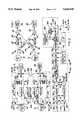
- FIG. 4is a diagrammatic view of a more detailed modification of the general circuit configuration shown in FIG. 1;
- FIG. 5is a diagrammatic view of a stereo detector circuit for use with the circuit shown in FIG. 4;
- FIG. 6is an enlarged graphical representation of a portion of the output signal curves shown in FIG. 2 and generated by the circuit shown in FIG. 4;
- FIG. 7is a graphical representation of the output of the shelving filter employed in the circuit of FIG. 4.
- the stereo imaging processing circuit 10comprising a left channel input line 12 as well as a right channel input line 14 receiving signals from a left channel source 16 and a right channel source 18 as diagrammatically represented in FIG. 1.
- the left channel source 16 and the right channel source 18may be parts of a single stereophonic reproduction component such as a tuner, preamp or the like.
- the circuit 10generates a left channel output line 20 and a right channel output line 22 coupled to respective transducers such as speakers 24 and 26.
- input line 12is branched to a crossfeed path 28 including a transfer function 30 which is added to the right channel direct path 32 by appropriate adding circuitry 34.
- the right channel input lineis branched through a crossfeed path 36 including a transfer function 38 which is added to a direct path 40 from the left channel input line 12 at an appropriate adding circuit 42.
- the crossfeed transfer functions 30 and 38contain a frequency weighting circuit.
- the transfer function employed in the preferred embodimentis shown in FIG. 3a and FIG. 3b.
- the magnitude of the function, as shown in FIG. 3a,is at a maximum above a predetermined frequency so that the lower frequency signal components of the channel inputs are substantially attenuated by the transfer function since such frequencies often have mono content.
- the rapidly changing phase response in FIG. 3bis due to a frequency independent delay, preferably between 2 and 10 milliseconds, which is part of the crossfeed transfer function.
- FIGS. 2a and 2bThe result of this signal processing is graphically demonstrated in FIGS. 2a and 2b.
- the plotted line 50represents left channel and right input channel signal spectrums.
- Plotted line 52indicates the sum of the signal strengths of the left and right channel.
- Line 54demonstrates the output signal spectrum of each channel output line 20 and 22, while line 56 demonstrates the sum of the signal strengths transmitted at output channels 20 and 22. It is desired that for a flat and equal input spectrums, the output spectrums should be flat and equal. However, this is not the case as can be seen in 54.
- a shelving filtercould be used to boost the low frequency signal power output to the same level as the higher frequency components. The effect of the boost is illustrated in phantom line at 55 in FIG. 2a.
- the gainsare controlled for a net 0 db output as described in greater detail below.
- the coherence of the left channel and right channel input lines 12 and 14is demonstrated at curve 58.
- the curve 58demonstrates that the lowest frequency signal components are substantially mono as they are reproduced substantially equally in both channels in prerecorded material. Conversely, the higher frequency signal components maintain their separated stereo imaging. In other words, the coherence is valued closer to 0 for the signal components with higher frequencies.
- Graphic trace 60demonstrates the fluctuating coherence of the output signal generated at the channel output lines 20 and 22.
- the output from the speakers 24 and 26is demonstrated to be coherent at numerous frequencies through a wide band while other frequency components remain entirely right or left channel outputs.
- the acoustic image of the sound reproductionis perceived to be narrower than the physical distance between the left channel speaker 24 and the right channel speaker 26.
- Such a featureis particularly useful when the speakers are located at the outermost borders of the passenger compartment of a motor vehicle.
- Mono inputcannot be avoided since the low-frequency content of most signals is mono as previously shown in FIG. 2b. Also, the voice content heard as normal speech on a stereo broadcast, and particular music pieces or passages are transmitted monaurally.
- the highpass response of the crossfeed pathsprevents the substantially mono low-frequency content from being crossfed.
- a circuit improvementwhich would turn off the imaging effect when the signal is significantly mono at frequencies that pass through the high pass filters will be desirable.
- the switchingis best accomplished by controlling the crossfeed gain in response to the amount of mono content in the signal that is crossfed.
- a gain control circuit with a stereo detectoris illustrated in the circuit configuration shown in FIGS. 4 and 5.
- the imaging circuit 100includes a shelving filter 53 in each transfer function 44 and 46 implemented by coupling a branch line to the channel input line.
- the left branch path 102includes a transfer function 104 in the form of a low pass filter whose output is added to the sum of the direct input line 40 and the crossfeed path 136.
- the transfer function 104 in branch line 102may be an exact complement of the high pass filter used for crossfeeding. These filters may be provided by a state-variable filter 103, as indicated diagrammatically in FIG. 4, so that the low pass and high pass functions are obtained simultaneously in an efficient signal processing manner.
- the right channel input line 114includes a branch line 106 with the transfer function 108 in the form of a low pass filter for adding to the sum of the direct line 132 and crossfeed path 128 from the left channel.
- each of the three signals added at each of the channel output lines 120 and 122must be multiplied by related gain constants in order to control the output response to obtain a flat power spectrum output.
- the gain of the crossfeed signalcontrols the amount of the imaging effect.
- the gains in each of the direct paths 140, 132 and in the branch paths 102 and 106are correspondingly controlled to compensate for or offset the crossfeed gain and keep the spectrum flat. The gain control will be discussed in greater detail with respect to FIG. 5.
- a transfer function 110 in the direct line 140can comprise an all-pass filter that has the same delay response as the low pass filter of transfer function 104.
- a further approachwould be to include an all-pass filter in the branch line 102 after the low pass filter to make the net response in the low pass path phase linear.
- the phase linear responsemeans that all frequencies have the same amount of delay.
- a corresponding constant delay 110would also be added to the direct path 140.
- similar filterswould be employed in the branch and direct lines of the opposite channel.
- the most preferred approachis to approximate the delay of the low pass filter in the branch path by imposing a constant delay 110 in path 140.
- the use of a constant delayis justified by the fact that frequencies from 0 to about the corner frequency of the low pass filter have a generally constant delay.
- Appropriate selection of a predetermined delay in the direct pathcan reduce the ripple in the output power spectrum to as low as plus or minus 0.08 db as is illustrated in FIG. 6 at curve 113.
- the output power spectrumhas a 0.5db dip at the corner frequency as demonstrated by curve 112 in FIG. 6.
- the amount of constant delay added to the direct path 140must also be added to the crossfeed path 136 to keep the net delay between these paths the same as they are added at the adder circuit 120.
- the right channel processor pathscan be modified as discussed above with respect to the left channel paths, and the discussion need not be repeated in order to provide a complete disclosure. Nevertheless the shelving filter output is adjusted as shown at 64 in FIG. 7 and closely conforms with the ideal shelving filter output curve 66.
- FIG. 5a preferred gain control mechanism with a stereo detector for automatically controlling the crossfeed gains provides two useful functions.
- the gain G of the crossfeed pathcan be automatically varied in response to the stereo content of the signals running through the left and right channel inputs.
- the imaging effectcan be varied as desired by the listener in order to produce the desired acoustical effect.
- FIG. 5diagrammatically represents the circuit features of signal processing according to the present invention to generate the crossfeed gain G with control signal 160.
- the circuitgenerates the compensating gain GA with control signal 150 for the direct paths 140 and 132 and the compensating gain GB with control signal 152 in the branch paths 102 and 106 that maintain a flat power output spectrum by offsetting the varying crossfeed gain generated as a function of the stereo separation detected.
- a high pass filtered signal 147 from the left-to-right crossfeed path 128 and a similar signal 149 from the crossfeed path 136are introduced to the adder 151 and subtractor 153 as shown.
- the sum of and the difference between the left channel signal and the right channel signalare generated and then envelope--detected to determine their respective levels.
- the left signal levelequals the right signal level and so the detected difference level is 0.
- the detected difference levelis non-zero.
- the detected difference levelvaries according to the amount of stereo content.
- the detected difference levelalso changes according to the absolute levels of the left and right signals.
- the detected differenceis normalized. Accordingly, the detected difference is divided by the detected sum of the left and right signals as at 170 to provide a quantity representing the amount of stereo content N in the signal.
- the result(called N) varies from 0 for fully coherent left and right signals to 1 for fully non-coherent left and right signals.
- the basic stereo detector circuit 154 of the preferred embodimentincludes an additive gain reducing function 164.
- an absolute value detector 165provides an output signal that is integrated at 166 with a predetermined integrator attack time constant and a predetermined integrator decay time constant, preferably in the range of one millisecond and one hundred milliseconds, respectively.
- the signalsare then simultaneously decimated as diagrammatically shown at 167, preferably reducing the sampling rate by an 8 to 1 ratio, to reduce the number of samples which need to be used in order to calculate the difference to sum ratio. Decimation is appropriate since the integrators reduce the signal bandwidth, thus allowing a lower sample rate. Decimation reduces the computational load for the subsequent processing shown in FIG. 5.
- the decimated resultis predivided at 168 to avoid complications under special conditions such as when the detected sum level is 0 and when the detected difference is larger than the detected sum due to the operation of the envelope detectors 165.
- the sensitivity controlcontrols how much the crossfeed gain G is affected by the stereo detector.
- a factor of 2 at control 174allows a multiplied net sensitivity of 0 to 2.
- sensitivitycan also be adjusted by an arbitrary curve function 176.
- the function 176provides a piece wise linear curve that varies the rate of change of the signal level with respect to the amount of stereo content in the signal.
- a modified stereo content signal output from the curve circuit 176is subjected to a dead zone function in order to prevent small changes in the signal level N due to noise or other inconsistencies, from modulating the crossfeed gain.
- An adjustable dead zone circuit 178provides a dead zone around the current value of the modified signal representing crossfeed gain, so that the gain output of the circuit 156 changes only when large changes occur. When the input to the function circuit 178 increases or decreases more than the width of the dead zone, the gain is automatically increased or lowered. As a result, noise or distortion does not modulate the crossfeed gain affecting the right and left output signals.
- the dead zone circuit 178includes a manual adjustor 180 for varying the width of the dead zone.
- a limit function 182may be used to limit the value of the crossfeed gain or to turn off the imaging effect if desired.
- a limit adjustor 184controls the limit imposed upon the crossfeed gain control signal before the signal is delivered to the gain controllers in the crossfeed paths 128 and 136.
- the compensator 186varies the compensatory gain control signals applied to the gain controllers in the direct paths 132 and 140 as well as in the branch paths 102 and 106 to maintain a flat power output at the channel outputs 120 and 122.
- the present inventionprovides a signal processor for reducing the width of the stereo image produced during stereophonic reproduction.
- the present inventioneliminates the hole-in-the-middle response typically associated with sound reproduction systems having widely spaced speaker locations with respect to the listener position.
- the automatic gain controlautomatically varies the amount of imaging effect in response to the amount of stereo content being delivered to the processor.
- the circuitis arranged so as to provide a flat power output response given a flat input response and it avoids frequency coloration of the sound output produced.
- the stereo detector circuitmay also be employed for other imaging or signal functions.
- DSPdigital signal processing
Landscapes
- Physics & Mathematics (AREA)
- Engineering & Computer Science (AREA)
- Acoustics & Sound (AREA)
- Signal Processing (AREA)
- Stereophonic System (AREA)
Abstract
Description
Claims (29)
Priority Applications (2)
| Application Number | Priority Date | Filing Date | Title |
|---|---|---|---|
| US07/888,087US5420929A (en) | 1992-05-26 | 1992-05-26 | Signal processor for sound image enhancement |
| JP5121566AJPH06141399A (en) | 1992-05-26 | 1993-05-24 | Signal processor for enhancement of sound image |
Applications Claiming Priority (1)
| Application Number | Priority Date | Filing Date | Title |
|---|---|---|---|
| US07/888,087US5420929A (en) | 1992-05-26 | 1992-05-26 | Signal processor for sound image enhancement |
Publications (1)
| Publication Number | Publication Date |
|---|---|
| US5420929Atrue US5420929A (en) | 1995-05-30 |
Family
ID=25392503
Family Applications (1)
| Application Number | Title | Priority Date | Filing Date |
|---|---|---|---|
| US07/888,087Expired - Fee RelatedUS5420929A (en) | 1992-05-26 | 1992-05-26 | Signal processor for sound image enhancement |
Country Status (2)
| Country | Link |
|---|---|
| US (1) | US5420929A (en) |
| JP (1) | JPH06141399A (en) |
Cited By (47)
| Publication number | Priority date | Publication date | Assignee | Title |
|---|---|---|---|---|
| EP0776144A1 (en)* | 1995-11-25 | 1997-05-28 | Deutsche ITT Industries GmbH | Signal modification circuit |
| US5692050A (en)* | 1995-06-15 | 1997-11-25 | Binaura Corporation | Method and apparatus for spatially enhancing stereo and monophonic signals |
| EP0743640A3 (en)* | 1995-05-17 | 1998-11-11 | Samsung Electronics Co., Ltd. | Audio processing unit for mixing L channel and R channel of CD/CD-I audio signal |
| US5850453A (en)* | 1995-07-28 | 1998-12-15 | Srs Labs, Inc. | Acoustic correction apparatus |
| US5862228A (en)* | 1997-02-21 | 1999-01-19 | Dolby Laboratories Licensing Corporation | Audio matrix encoding |
| US5910990A (en)* | 1996-11-20 | 1999-06-08 | Electronics And Telecommunications Research Institute | Apparatus and method for automatic equalization of personal multi-channel audio system |
| US5912975A (en)* | 1995-06-30 | 1999-06-15 | Philips Electronics North America Corp | Method and circuit for creating phantom sources using phase shifting circuitry |
| US5983087A (en)* | 1997-06-26 | 1999-11-09 | Delco Electronics Corporation | Distributed digital signal processing for vehicle audio systems |
| US6111958A (en)* | 1997-03-21 | 2000-08-29 | Euphonics, Incorporated | Audio spatial enhancement apparatus and methods |
| US6307941B1 (en)* | 1997-07-15 | 2001-10-23 | Desper Products, Inc. | System and method for localization of virtual sound |
| US6363155B1 (en)* | 1997-09-24 | 2002-03-26 | Studer Professional Audio Ag | Process and device for mixing sound signals |
| US20020097880A1 (en)* | 2001-01-19 | 2002-07-25 | Ole Kirkeby | Transparent stereo widening algorithm for loudspeakers |
| US6449368B1 (en) | 1997-03-14 | 2002-09-10 | Dolby Laboratories Licensing Corporation | Multidirectional audio decoding |
| US20030194098A1 (en)* | 1999-10-20 | 2003-10-16 | Werner Bernard M. | Mid-range loudspeaker |
| WO2003104924A2 (en) | 2002-06-05 | 2003-12-18 | Sonic Focus, Inc. | Acoustical virtual reality engine and advanced techniques for enhancing delivered sound |
| KR20040048104A (en)* | 2002-12-02 | 2004-06-07 | 주식회사 쓰리에스테크놀로지 | 3D Audio Processing System for the Portable Equipment |
| US20050147254A1 (en)* | 2000-06-28 | 2005-07-07 | Coats Elon R. | Sub-harmonic generator and stereo expansion processor |
| US7031474B1 (en) | 1999-10-04 | 2006-04-18 | Srs Labs, Inc. | Acoustic correction apparatus |
| US20080022009A1 (en)* | 1999-12-10 | 2008-01-24 | Srs Labs, Inc | System and method for enhanced streaming audio |
| US20100316224A1 (en)* | 2009-06-12 | 2010-12-16 | Conexant Systems, Inc. | Systems and methods for creating immersion surround sound and virtual speakers effects |
| US8050434B1 (en) | 2006-12-21 | 2011-11-01 | Srs Labs, Inc. | Multi-channel audio enhancement system |
| US8121318B1 (en) | 2008-05-08 | 2012-02-21 | Ambourn Paul R | Two channel audio surround sound circuit with automatic level control |
| EP2814267A1 (en)* | 2013-06-12 | 2014-12-17 | Bongiovi Acoustics LLC | System and method for stereo field enhancement in two-channel audio systems |
| US9258664B2 (en) | 2013-05-23 | 2016-02-09 | Comhear, Inc. | Headphone audio enhancement system |
| US9615189B2 (en) | 2014-08-08 | 2017-04-04 | Bongiovi Acoustics Llc | Artificial ear apparatus and associated methods for generating a head related audio transfer function |
| US9621994B1 (en) | 2015-11-16 | 2017-04-11 | Bongiovi Acoustics Llc | Surface acoustic transducer |
| US9615813B2 (en) | 2014-04-16 | 2017-04-11 | Bongiovi Acoustics Llc. | Device for wide-band auscultation |
| US9638672B2 (en) | 2015-03-06 | 2017-05-02 | Bongiovi Acoustics Llc | System and method for acquiring acoustic information from a resonating body |
| US9741355B2 (en) | 2013-06-12 | 2017-08-22 | Bongiovi Acoustics Llc | System and method for narrow bandwidth digital signal processing |
| US9793872B2 (en) | 2006-02-07 | 2017-10-17 | Bongiovi Acoustics Llc | System and method for digital signal processing |
| US9883318B2 (en) | 2013-06-12 | 2018-01-30 | Bongiovi Acoustics Llc | System and method for stereo field enhancement in two-channel audio systems |
| US9906867B2 (en) | 2015-11-16 | 2018-02-27 | Bongiovi Acoustics Llc | Surface acoustic transducer |
| US9906858B2 (en) | 2013-10-22 | 2018-02-27 | Bongiovi Acoustics Llc | System and method for digital signal processing |
| US10069471B2 (en) | 2006-02-07 | 2018-09-04 | Bongiovi Acoustics Llc | System and method for digital signal processing |
| US10158337B2 (en) | 2004-08-10 | 2018-12-18 | Bongiovi Acoustics Llc | System and method for digital signal processing |
| US10639000B2 (en) | 2014-04-16 | 2020-05-05 | Bongiovi Acoustics Llc | Device for wide-band auscultation |
| US10701505B2 (en) | 2006-02-07 | 2020-06-30 | Bongiovi Acoustics Llc. | System, method, and apparatus for generating and digitally processing a head related audio transfer function |
| US10820883B2 (en) | 2014-04-16 | 2020-11-03 | Bongiovi Acoustics Llc | Noise reduction assembly for auscultation of a body |
| US10848867B2 (en) | 2006-02-07 | 2020-11-24 | Bongiovi Acoustics Llc | System and method for digital signal processing |
| US10848118B2 (en) | 2004-08-10 | 2020-11-24 | Bongiovi Acoustics Llc | System and method for digital signal processing |
| US10959035B2 (en) | 2018-08-02 | 2021-03-23 | Bongiovi Acoustics Llc | System, method, and apparatus for generating and digitally processing a head related audio transfer function |
| CN112702681A (en)* | 2019-10-23 | 2021-04-23 | 北京小米移动软件有限公司 | Stereo audio equipment, power supply control method and device thereof, and mobile terminal |
| EP3807877A4 (en)* | 2018-06-12 | 2021-08-04 | Magic Leap, Inc. | CONTROLLING LOW FREQUENCY COHERENCE BETWEEN CHANNELS |
| US11202161B2 (en) | 2006-02-07 | 2021-12-14 | Bongiovi Acoustics Llc | System, method, and apparatus for generating and digitally processing a head related audio transfer function |
| US11211043B2 (en) | 2018-04-11 | 2021-12-28 | Bongiovi Acoustics Llc | Audio enhanced hearing protection system |
| US11431312B2 (en) | 2004-08-10 | 2022-08-30 | Bongiovi Acoustics Llc | System and method for digital signal processing |
| US11665495B2 (en) | 2020-09-18 | 2023-05-30 | Nicolas John Gault | Methods, systems, apparatuses, and devices for facilitating enhanced perception of ambiance soundstage and imaging in headphones and comprehensive linearization of in-ear monitors |
Families Citing this family (1)
| Publication number | Priority date | Publication date | Assignee | Title |
|---|---|---|---|---|
| TWI657701B (en)* | 2016-06-17 | 2019-04-21 | 中國商信泰光學(深圳)有限公司 | Headphone device |
Citations (13)
| Publication number | Priority date | Publication date | Assignee | Title |
|---|---|---|---|---|
| US4060696A (en)* | 1975-06-20 | 1977-11-29 | Victor Company Of Japan, Limited | Binaural four-channel stereophony |
| US4192969A (en)* | 1977-09-10 | 1980-03-11 | Makoto Iwahara | Stage-expanded stereophonic sound reproduction |
| US4219696A (en)* | 1977-02-18 | 1980-08-26 | Matsushita Electric Industrial Co., Ltd. | Sound image localization control system |
| US4309570A (en)* | 1979-04-05 | 1982-01-05 | Carver R W | Dimensional sound recording and apparatus and method for producing the same |
| US4329544A (en)* | 1979-05-18 | 1982-05-11 | Matsushita Electric Industrial Co., Ltd. | Sound reproduction system for motor vehicle |
| US4388494A (en)* | 1980-01-12 | 1983-06-14 | Schoene Peter | Process and apparatus for improved dummy head stereophonic reproduction |
| US4394536A (en)* | 1980-06-12 | 1983-07-19 | Mitsubishi Denki Kabushiki Kaisha | Sound reproduction device |
| WO1984001257A1 (en)* | 1982-09-14 | 1984-03-29 | Boyd & Haas Gmbh & Co Kg | Method and device for the reception and restitution of acoustic events |
| US4495637A (en)* | 1982-07-23 | 1985-01-22 | Sci-Coustics, Inc. | Apparatus and method for enhanced psychoacoustic imagery using asymmetric cross-channel feed |
| US4603429A (en)* | 1979-04-05 | 1986-07-29 | Carver R W | Dimensional sound recording and apparatus and method for producing the same |
| US4622689A (en)* | 1984-02-01 | 1986-11-11 | Hobrough Gilbert L | Stereophonic sound system |
| US4868878A (en)* | 1984-04-09 | 1989-09-19 | Pioneer Electronic Corporation | Sound field correction system |
| US4980915A (en)* | 1988-08-12 | 1990-12-25 | Sanyo Electric Co., Ltd. | Center mode control circuit |
- 1992
- 1992-05-26USUS07/888,087patent/US5420929A/ennot_activeExpired - Fee Related
- 1993
- 1993-05-24JPJP5121566Apatent/JPH06141399A/enactivePending
Patent Citations (14)
| Publication number | Priority date | Publication date | Assignee | Title |
|---|---|---|---|---|
| US4060696A (en)* | 1975-06-20 | 1977-11-29 | Victor Company Of Japan, Limited | Binaural four-channel stereophony |
| US4219696A (en)* | 1977-02-18 | 1980-08-26 | Matsushita Electric Industrial Co., Ltd. | Sound image localization control system |
| US4192969A (en)* | 1977-09-10 | 1980-03-11 | Makoto Iwahara | Stage-expanded stereophonic sound reproduction |
| US4603429A (en)* | 1979-04-05 | 1986-07-29 | Carver R W | Dimensional sound recording and apparatus and method for producing the same |
| US4309570A (en)* | 1979-04-05 | 1982-01-05 | Carver R W | Dimensional sound recording and apparatus and method for producing the same |
| US4329544A (en)* | 1979-05-18 | 1982-05-11 | Matsushita Electric Industrial Co., Ltd. | Sound reproduction system for motor vehicle |
| US4388494A (en)* | 1980-01-12 | 1983-06-14 | Schoene Peter | Process and apparatus for improved dummy head stereophonic reproduction |
| US4394536A (en)* | 1980-06-12 | 1983-07-19 | Mitsubishi Denki Kabushiki Kaisha | Sound reproduction device |
| US4495637A (en)* | 1982-07-23 | 1985-01-22 | Sci-Coustics, Inc. | Apparatus and method for enhanced psychoacoustic imagery using asymmetric cross-channel feed |
| WO1984001257A1 (en)* | 1982-09-14 | 1984-03-29 | Boyd & Haas Gmbh & Co Kg | Method and device for the reception and restitution of acoustic events |
| US4622689A (en)* | 1984-02-01 | 1986-11-11 | Hobrough Gilbert L | Stereophonic sound system |
| US4868878A (en)* | 1984-04-09 | 1989-09-19 | Pioneer Electronic Corporation | Sound field correction system |
| US4980914A (en)* | 1984-04-09 | 1990-12-25 | Pioneer Electronic Corporation | Sound field correction system |
| US4980915A (en)* | 1988-08-12 | 1990-12-25 | Sanyo Electric Co., Ltd. | Center mode control circuit |
Cited By (87)
| Publication number | Priority date | Publication date | Assignee | Title |
|---|---|---|---|---|
| EP0743640A3 (en)* | 1995-05-17 | 1998-11-11 | Samsung Electronics Co., Ltd. | Audio processing unit for mixing L channel and R channel of CD/CD-I audio signal |
| US5692050A (en)* | 1995-06-15 | 1997-11-25 | Binaura Corporation | Method and apparatus for spatially enhancing stereo and monophonic signals |
| US5912975A (en)* | 1995-06-30 | 1999-06-15 | Philips Electronics North America Corp | Method and circuit for creating phantom sources using phase shifting circuitry |
| US5850453A (en)* | 1995-07-28 | 1998-12-15 | Srs Labs, Inc. | Acoustic correction apparatus |
| US20040247132A1 (en)* | 1995-07-28 | 2004-12-09 | Klayman Arnold I. | Acoustic correction apparatus |
| US20060062395A1 (en)* | 1995-07-28 | 2006-03-23 | Klayman Arnold I | Acoustic correction apparatus |
| US7043031B2 (en) | 1995-07-28 | 2006-05-09 | Srs Labs, Inc. | Acoustic correction apparatus |
| US6718039B1 (en) | 1995-07-28 | 2004-04-06 | Srs Labs, Inc. | Acoustic correction apparatus |
| US7555130B2 (en) | 1995-07-28 | 2009-06-30 | Srs Labs, Inc. | Acoustic correction apparatus |
| EP0776144A1 (en)* | 1995-11-25 | 1997-05-28 | Deutsche ITT Industries GmbH | Signal modification circuit |
| US5910990A (en)* | 1996-11-20 | 1999-06-08 | Electronics And Telecommunications Research Institute | Apparatus and method for automatic equalization of personal multi-channel audio system |
| US5862228A (en)* | 1997-02-21 | 1999-01-19 | Dolby Laboratories Licensing Corporation | Audio matrix encoding |
| US6449368B1 (en) | 1997-03-14 | 2002-09-10 | Dolby Laboratories Licensing Corporation | Multidirectional audio decoding |
| US6111958A (en)* | 1997-03-21 | 2000-08-29 | Euphonics, Incorporated | Audio spatial enhancement apparatus and methods |
| US5983087A (en)* | 1997-06-26 | 1999-11-09 | Delco Electronics Corporation | Distributed digital signal processing for vehicle audio systems |
| US6307941B1 (en)* | 1997-07-15 | 2001-10-23 | Desper Products, Inc. | System and method for localization of virtual sound |
| US6363155B1 (en)* | 1997-09-24 | 2002-03-26 | Studer Professional Audio Ag | Process and device for mixing sound signals |
| US7907736B2 (en) | 1999-10-04 | 2011-03-15 | Srs Labs, Inc. | Acoustic correction apparatus |
| US20060126851A1 (en)* | 1999-10-04 | 2006-06-15 | Yuen Thomas C | Acoustic correction apparatus |
| US7031474B1 (en) | 1999-10-04 | 2006-04-18 | Srs Labs, Inc. | Acoustic correction apparatus |
| US20030194098A1 (en)* | 1999-10-20 | 2003-10-16 | Werner Bernard M. | Mid-range loudspeaker |
| US7027605B2 (en)* | 1999-10-20 | 2006-04-11 | Harman International Industries, Incorporated | Mid-range loudspeaker |
| US8751028B2 (en) | 1999-12-10 | 2014-06-10 | Dts Llc | System and method for enhanced streaming audio |
| US7987281B2 (en) | 1999-12-10 | 2011-07-26 | Srs Labs, Inc. | System and method for enhanced streaming audio |
| US20080022009A1 (en)* | 1999-12-10 | 2008-01-24 | Srs Labs, Inc | System and method for enhanced streaming audio |
| US7203320B2 (en)* | 2000-06-28 | 2007-04-10 | Peavey Electronics Corporation | Sub-harmonic generator and stereo expansion processor |
| US20050147254A1 (en)* | 2000-06-28 | 2005-07-07 | Coats Elon R. | Sub-harmonic generator and stereo expansion processor |
| EP1225789A3 (en)* | 2001-01-19 | 2004-09-08 | Nokia Corporation | A stereo widening algorithm for loudspeakers |
| US20020097880A1 (en)* | 2001-01-19 | 2002-07-25 | Ole Kirkeby | Transparent stereo widening algorithm for loudspeakers |
| US6928168B2 (en) | 2001-01-19 | 2005-08-09 | Nokia Corporation | Transparent stereo widening algorithm for loudspeakers |
| US20060098827A1 (en)* | 2002-06-05 | 2006-05-11 | Thomas Paddock | Acoustical virtual reality engine and advanced techniques for enhancing delivered sound |
| WO2003104924A3 (en)* | 2002-06-05 | 2004-11-25 | Sonic Focus Inc | Acoustical virtual reality engine and advanced techniques for enhancing delivered sound |
| WO2003104924A2 (en) | 2002-06-05 | 2003-12-18 | Sonic Focus, Inc. | Acoustical virtual reality engine and advanced techniques for enhancing delivered sound |
| US8676361B2 (en) | 2002-06-05 | 2014-03-18 | Synopsys, Inc. | Acoustical virtual reality engine and advanced techniques for enhancing delivered sound |
| KR20040048104A (en)* | 2002-12-02 | 2004-06-07 | 주식회사 쓰리에스테크놀로지 | 3D Audio Processing System for the Portable Equipment |
| US10666216B2 (en) | 2004-08-10 | 2020-05-26 | Bongiovi Acoustics Llc | System and method for digital signal processing |
| US11431312B2 (en) | 2004-08-10 | 2022-08-30 | Bongiovi Acoustics Llc | System and method for digital signal processing |
| US10158337B2 (en) | 2004-08-10 | 2018-12-18 | Bongiovi Acoustics Llc | System and method for digital signal processing |
| US10848118B2 (en) | 2004-08-10 | 2020-11-24 | Bongiovi Acoustics Llc | System and method for digital signal processing |
| US9793872B2 (en) | 2006-02-07 | 2017-10-17 | Bongiovi Acoustics Llc | System and method for digital signal processing |
| US10701505B2 (en) | 2006-02-07 | 2020-06-30 | Bongiovi Acoustics Llc. | System, method, and apparatus for generating and digitally processing a head related audio transfer function |
| US10291195B2 (en) | 2006-02-07 | 2019-05-14 | Bongiovi Acoustics Llc | System and method for digital signal processing |
| US10848867B2 (en) | 2006-02-07 | 2020-11-24 | Bongiovi Acoustics Llc | System and method for digital signal processing |
| US11425499B2 (en) | 2006-02-07 | 2022-08-23 | Bongiovi Acoustics Llc | System and method for digital signal processing |
| US10069471B2 (en) | 2006-02-07 | 2018-09-04 | Bongiovi Acoustics Llc | System and method for digital signal processing |
| US11202161B2 (en) | 2006-02-07 | 2021-12-14 | Bongiovi Acoustics Llc | System, method, and apparatus for generating and digitally processing a head related audio transfer function |
| US9232312B2 (en) | 2006-12-21 | 2016-01-05 | Dts Llc | Multi-channel audio enhancement system |
| US8509464B1 (en) | 2006-12-21 | 2013-08-13 | Dts Llc | Multi-channel audio enhancement system |
| US8050434B1 (en) | 2006-12-21 | 2011-11-01 | Srs Labs, Inc. | Multi-channel audio enhancement system |
| US8121318B1 (en) | 2008-05-08 | 2012-02-21 | Ambourn Paul R | Two channel audio surround sound circuit with automatic level control |
| US8577065B2 (en)* | 2009-06-12 | 2013-11-05 | Conexant Systems, Inc. | Systems and methods for creating immersion surround sound and virtual speakers effects |
| US20100316224A1 (en)* | 2009-06-12 | 2010-12-16 | Conexant Systems, Inc. | Systems and methods for creating immersion surround sound and virtual speakers effects |
| US9258664B2 (en) | 2013-05-23 | 2016-02-09 | Comhear, Inc. | Headphone audio enhancement system |
| US9866963B2 (en) | 2013-05-23 | 2018-01-09 | Comhear, Inc. | Headphone audio enhancement system |
| US10284955B2 (en) | 2013-05-23 | 2019-05-07 | Comhear, Inc. | Headphone audio enhancement system |
| CN104620602B (en)* | 2013-06-12 | 2017-12-29 | 鹏奇欧维声学有限公司 | System and method for stereo field enhancement in two-channel audio system |
| CN107979796B (en)* | 2013-06-12 | 2019-12-31 | 鹏奇欧维声学有限公司 | System and method for stereo field enhancement in a two-channel audio system |
| EP2814267A1 (en)* | 2013-06-12 | 2014-12-17 | Bongiovi Acoustics LLC | System and method for stereo field enhancement in two-channel audio systems |
| US9883318B2 (en) | 2013-06-12 | 2018-01-30 | Bongiovi Acoustics Llc | System and method for stereo field enhancement in two-channel audio systems |
| AU2014203188B2 (en)* | 2013-06-12 | 2018-04-12 | Bongiovi Acoustics Llc. | System and method for stereo field enhancement in two-channel audio system |
| TWI722529B (en)* | 2013-06-12 | 2021-03-21 | 美商鵬奇歐維聲學有限公司 | System and method for stereo field enhancement in two-channel audio systems |
| US10999695B2 (en) | 2013-06-12 | 2021-05-04 | Bongiovi Acoustics Llc | System and method for stereo field enhancement in two channel audio systems |
| US9741355B2 (en) | 2013-06-12 | 2017-08-22 | Bongiovi Acoustics Llc | System and method for narrow bandwidth digital signal processing |
| US10412533B2 (en) | 2013-06-12 | 2019-09-10 | Bongiovi Acoustics Llc | System and method for stereo field enhancement in two-channel audio systems |
| TWI674008B (en)* | 2013-06-12 | 2019-10-01 | 美商鵬奇歐維聲學有限公司 | System and method for stereo field enhancement in two-channel audio systems |
| CN107979796A (en)* | 2013-06-12 | 2018-05-01 | 鹏奇欧维声学有限公司 | System and method for the stereo field domain enhancing in two-channel audio system |
| CN104620602A (en)* | 2013-06-12 | 2015-05-13 | 鹏奇欧维声学有限公司 | System and method for stereo field enhancement in two-channel audio system |
| US10313791B2 (en) | 2013-10-22 | 2019-06-04 | Bongiovi Acoustics Llc | System and method for digital signal processing |
| US11418881B2 (en) | 2013-10-22 | 2022-08-16 | Bongiovi Acoustics Llc | System and method for digital signal processing |
| US10917722B2 (en) | 2013-10-22 | 2021-02-09 | Bongiovi Acoustics, Llc | System and method for digital signal processing |
| US9906858B2 (en) | 2013-10-22 | 2018-02-27 | Bongiovi Acoustics Llc | System and method for digital signal processing |
| US10820883B2 (en) | 2014-04-16 | 2020-11-03 | Bongiovi Acoustics Llc | Noise reduction assembly for auscultation of a body |
| US11284854B2 (en) | 2014-04-16 | 2022-03-29 | Bongiovi Acoustics Llc | Noise reduction assembly for auscultation of a body |
| US9615813B2 (en) | 2014-04-16 | 2017-04-11 | Bongiovi Acoustics Llc. | Device for wide-band auscultation |
| US10639000B2 (en) | 2014-04-16 | 2020-05-05 | Bongiovi Acoustics Llc | Device for wide-band auscultation |
| US9615189B2 (en) | 2014-08-08 | 2017-04-04 | Bongiovi Acoustics Llc | Artificial ear apparatus and associated methods for generating a head related audio transfer function |
| US9638672B2 (en) | 2015-03-06 | 2017-05-02 | Bongiovi Acoustics Llc | System and method for acquiring acoustic information from a resonating body |
| US9906867B2 (en) | 2015-11-16 | 2018-02-27 | Bongiovi Acoustics Llc | Surface acoustic transducer |
| US9621994B1 (en) | 2015-11-16 | 2017-04-11 | Bongiovi Acoustics Llc | Surface acoustic transducer |
| US9998832B2 (en) | 2015-11-16 | 2018-06-12 | Bongiovi Acoustics Llc | Surface acoustic transducer |
| US11211043B2 (en) | 2018-04-11 | 2021-12-28 | Bongiovi Acoustics Llc | Audio enhanced hearing protection system |
| EP3807877A4 (en)* | 2018-06-12 | 2021-08-04 | Magic Leap, Inc. | CONTROLLING LOW FREQUENCY COHERENCE BETWEEN CHANNELS |
| US11252528B2 (en) | 2018-06-12 | 2022-02-15 | Magic Leap, Inc. | Low-frequency interchannel coherence control |
| US10959035B2 (en) | 2018-08-02 | 2021-03-23 | Bongiovi Acoustics Llc | System, method, and apparatus for generating and digitally processing a head related audio transfer function |
| CN112702681A (en)* | 2019-10-23 | 2021-04-23 | 北京小米移动软件有限公司 | Stereo audio equipment, power supply control method and device thereof, and mobile terminal |
| CN112702681B (en)* | 2019-10-23 | 2022-04-08 | 北京小米移动软件有限公司 | Stereo audio equipment, power supply control method and device thereof, and mobile terminal |
| US11665495B2 (en) | 2020-09-18 | 2023-05-30 | Nicolas John Gault | Methods, systems, apparatuses, and devices for facilitating enhanced perception of ambiance soundstage and imaging in headphones and comprehensive linearization of in-ear monitors |
Also Published As
| Publication number | Publication date |
|---|---|
| JPH06141399A (en) | 1994-05-20 |
Similar Documents
| Publication | Publication Date | Title |
|---|---|---|
| US5420929A (en) | Signal processor for sound image enhancement | |
| KR930004933B1 (en) | Stereo enhancement and directivity servo | |
| EP0479395B1 (en) | Stereo enhancement system | |
| JP3193032B2 (en) | In-vehicle automatic volume control device | |
| CA2228051C (en) | Acoustic correction apparatus | |
| US7369666B2 (en) | Audio reproducing system | |
| JP2004056527A (en) | Frequency characteristic adjusting device and method therefor | |
| JPH05219600A (en) | Audio surround system with stereo intensifying and directive servo | |
| JPH077350A (en) | Acoustic reproduction system | |
| JPH0136317B2 (en) | ||
| US5241604A (en) | Sound effect apparatus | |
| US4283600A (en) | Recirculationless concert hall simulation and enhancement system | |
| US8009834B2 (en) | Sound reproduction apparatus and method of enhancing low frequency component | |
| KR0129429B1 (en) | Audio signal processing device | |
| US5774556A (en) | Stereo enhancement system including sound localization filters | |
| JP2541062B2 (en) | Sound reproduction device | |
| JPH071855B2 (en) | Automatic loudness compensator for in-vehicle sound reproduction device | |
| JP2005506781A (en) | Device for amplifying bass frequencies | |
| JPH01223895A (en) | Acoustic reproducing device | |
| JPH0418760B2 (en) | ||
| KR940000106Y1 (en) | Ultra low and stereo sound signal processing circuit | |
| WO1998054927A1 (en) | Method and system for enhancing the audio image created by an audio signal | |
| HK1002150B (en) | Stereo enhancement and directivity servo | |
| JPH04151699A (en) | On-vehicle audio system | |
| JPH05168099A (en) | Acoustic system |
Legal Events
| Date | Code | Title | Description |
|---|---|---|---|
| AS | Assignment | Owner name:FORD MOTOR COMPANY, A CORP. OF DE, MICHIGAN Free format text:ASSIGNMENT OF ASSIGNORS INTEREST.;ASSIGNORS:GEDDES, EARL R.;WHIKEHART, J. WILLIAM;REEL/FRAME:006172/0368 Effective date:19920518 | |
| FPAY | Fee payment | Year of fee payment:4 | |
| AS | Assignment | Owner name:VISTEON GLOBAL TECHNOLOGIES, INC., MICHIGAN Free format text:ASSIGNMENT OF ASSIGNORS INTEREST;ASSIGNOR:FORD MOTOR COMPANY;REEL/FRAME:010968/0220 Effective date:20000615 | |
| FPAY | Fee payment | Year of fee payment:8 | |
| REMI | Maintenance fee reminder mailed | ||
| LAPS | Lapse for failure to pay maintenance fees | ||
| STCH | Information on status: patent discontinuation | Free format text:PATENT EXPIRED DUE TO NONPAYMENT OF MAINTENANCE FEES UNDER 37 CFR 1.362 | |
| FP | Lapsed due to failure to pay maintenance fee | Effective date:20070530 | |
| AS | Assignment | Owner name:JPMORGAN CHASE BANK, N.A., AS ADMINISTRATIVE AGENT Free format text:SECURITY AGREEMENT;ASSIGNOR:VISTEON GLOBAL TECHNOLOGIES, INC.;REEL/FRAME:020497/0733 Effective date:20060613 | |
| AS | Assignment | Owner name:JPMORGAN CHASE BANK, TEXAS Free format text:SECURITY INTEREST;ASSIGNOR:VISTEON GLOBAL TECHNOLOGIES, INC.;REEL/FRAME:022368/0001 Effective date:20060814 Owner name:JPMORGAN CHASE BANK,TEXAS Free format text:SECURITY INTEREST;ASSIGNOR:VISTEON GLOBAL TECHNOLOGIES, INC.;REEL/FRAME:022368/0001 Effective date:20060814 | |
| AS | Assignment | Owner name:WILMINGTON TRUST FSB, AS ADMINISTRATIVE AGENT, MIN Free format text:ASSIGNMENT OF SECURITY INTEREST IN PATENTS;ASSIGNOR:JPMORGAN CHASE BANK, N.A., AS ADMINISTRATIVE AGENT;REEL/FRAME:022575/0186 Effective date:20090415 Owner name:WILMINGTON TRUST FSB, AS ADMINISTRATIVE AGENT,MINN Free format text:ASSIGNMENT OF SECURITY INTEREST IN PATENTS;ASSIGNOR:JPMORGAN CHASE BANK, N.A., AS ADMINISTRATIVE AGENT;REEL/FRAME:022575/0186 Effective date:20090415 | |
| AS | Assignment | Owner name:VISTEON GLOBAL TECHNOLOGIES, INC., MICHIGAN Free format text:RELEASE BY SECURED PARTY AGAINST SECURITY INTEREST IN PATENTS RECORDED AT REEL 022575 FRAME 0186;ASSIGNOR:WILMINGTON TRUST FSB, AS ADMINISTRATIVE AGENT;REEL/FRAME:025105/0201 Effective date:20101001 |