US5420536A - Linearized power amplifier - Google Patents
Linearized power amplifierDownload PDFInfo
- Publication number
- US5420536A US5420536AUS08/212,946US21294694AUS5420536AUS 5420536 AUS5420536 AUS 5420536AUS 21294694 AUS21294694 AUS 21294694AUS 5420536 AUS5420536 AUS 5420536A
- Authority
- US
- United States
- Prior art keywords
- amplifier
- linearization
- power
- power amplifier
- linear
- Prior art date
- Legal status (The legal status is an assumption and is not a legal conclusion. Google has not performed a legal analysis and makes no representation as to the accuracy of the status listed.)
- Expired - Lifetime
Links
Images


Classifications
- H—ELECTRICITY
- H04—ELECTRIC COMMUNICATION TECHNIQUE
- H04L—TRANSMISSION OF DIGITAL INFORMATION, e.g. TELEGRAPHIC COMMUNICATION
- H04L27/00—Modulated-carrier systems
- H04L27/32—Carrier systems characterised by combinations of two or more of the types covered by groups H04L27/02, H04L27/10, H04L27/18 or H04L27/26
- H04L27/34—Amplitude- and phase-modulated carrier systems, e.g. quadrature-amplitude modulated carrier systems
- H04L27/36—Modulator circuits; Transmitter circuits
- H04L27/366—Arrangements for compensating undesirable properties of the transmission path between the modulator and the demodulator
- H04L27/367—Arrangements for compensating undesirable properties of the transmission path between the modulator and the demodulator using predistortion
- H04L27/368—Arrangements for compensating undesirable properties of the transmission path between the modulator and the demodulator using predistortion adaptive predistortion
- H—ELECTRICITY
- H03—ELECTRONIC CIRCUITRY
- H03C—MODULATION
- H03C3/00—Angle modulation
- H03C3/38—Angle modulation by converting amplitude modulation to angle modulation
- H03C3/40—Angle modulation by converting amplitude modulation to angle modulation using two signal paths the outputs of which have a predetermined phase difference and at least one output being amplitude-modulated
- H03C3/406—Angle modulation by converting amplitude modulation to angle modulation using two signal paths the outputs of which have a predetermined phase difference and at least one output being amplitude-modulated using a feedback loop containing mixers or demodulators
- H—ELECTRICITY
- H03—ELECTRONIC CIRCUITRY
- H03C—MODULATION
- H03C5/00—Amplitude modulation and angle modulation produced simultaneously or at will by the same modulating signal
- H—ELECTRICITY
- H03—ELECTRONIC CIRCUITRY
- H03F—AMPLIFIERS
- H03F1/00—Details of amplifiers with only discharge tubes, only semiconductor devices or only unspecified devices as amplifying elements
- H03F1/02—Modifications of amplifiers to raise the efficiency, e.g. gliding Class A stages, use of an auxiliary oscillation
- H03F1/0205—Modifications of amplifiers to raise the efficiency, e.g. gliding Class A stages, use of an auxiliary oscillation in transistor amplifiers
- H03F1/0211—Modifications of amplifiers to raise the efficiency, e.g. gliding Class A stages, use of an auxiliary oscillation in transistor amplifiers with control of the supply voltage or current
- H03F1/0216—Continuous control
- H03F1/0222—Continuous control by using a signal derived from the input signal
- H—ELECTRICITY
- H03—ELECTRONIC CIRCUITRY
- H03F—AMPLIFIERS
- H03F1/00—Details of amplifiers with only discharge tubes, only semiconductor devices or only unspecified devices as amplifying elements
- H03F1/02—Modifications of amplifiers to raise the efficiency, e.g. gliding Class A stages, use of an auxiliary oscillation
- H03F1/0205—Modifications of amplifiers to raise the efficiency, e.g. gliding Class A stages, use of an auxiliary oscillation in transistor amplifiers
- H03F1/0261—Modifications of amplifiers to raise the efficiency, e.g. gliding Class A stages, use of an auxiliary oscillation in transistor amplifiers with control of the polarisation voltage or current, e.g. gliding Class A
- H—ELECTRICITY
- H03—ELECTRONIC CIRCUITRY
- H03F—AMPLIFIERS
- H03F1/00—Details of amplifiers with only discharge tubes, only semiconductor devices or only unspecified devices as amplifying elements
- H03F1/32—Modifications of amplifiers to reduce non-linear distortion
- H03F1/3223—Modifications of amplifiers to reduce non-linear distortion using feed-forward
- H—ELECTRICITY
- H03—ELECTRONIC CIRCUITRY
- H03F—AMPLIFIERS
- H03F1/00—Details of amplifiers with only discharge tubes, only semiconductor devices or only unspecified devices as amplifying elements
- H03F1/32—Modifications of amplifiers to reduce non-linear distortion
- H03F1/3241—Modifications of amplifiers to reduce non-linear distortion using predistortion circuits
- H03F1/3247—Modifications of amplifiers to reduce non-linear distortion using predistortion circuits using feedback acting on predistortion circuits
- H—ELECTRICITY
- H03—ELECTRONIC CIRCUITRY
- H03F—AMPLIFIERS
- H03F1/00—Details of amplifiers with only discharge tubes, only semiconductor devices or only unspecified devices as amplifying elements
- H03F1/34—Negative-feedback-circuit arrangements with or without positive feedback
- H03F1/345—Negative-feedback-circuit arrangements with or without positive feedback using hybrid or directional couplers
- H—ELECTRICITY
- H03—ELECTRONIC CIRCUITRY
- H03F—AMPLIFIERS
- H03F3/00—Amplifiers with only discharge tubes or only semiconductor devices as amplifying elements
- H03F3/20—Power amplifiers, e.g. Class B amplifiers, Class C amplifiers
- H03F3/24—Power amplifiers, e.g. Class B amplifiers, Class C amplifiers of transmitter output stages
- H—ELECTRICITY
- H03—ELECTRONIC CIRCUITRY
- H03G—CONTROL OF AMPLIFICATION
- H03G3/00—Gain control in amplifiers or frequency changers
- H03G3/20—Automatic control
- H03G3/30—Automatic control in amplifiers having semiconductor devices
- H03G3/3036—Automatic control in amplifiers having semiconductor devices in high-frequency amplifiers or in frequency-changers
- H03G3/3042—Automatic control in amplifiers having semiconductor devices in high-frequency amplifiers or in frequency-changers in modulators, frequency-changers, transmitters or power amplifiers
- H—ELECTRICITY
- H03—ELECTRONIC CIRCUITRY
- H03F—AMPLIFIERS
- H03F2200/00—Indexing scheme relating to amplifiers
- H03F2200/102—A non-specified detector of a signal envelope being used in an amplifying circuit
- H—ELECTRICITY
- H03—ELECTRONIC CIRCUITRY
- H03F—AMPLIFIERS
- H03F2200/00—Indexing scheme relating to amplifiers
- H03F2200/57—Separate feedback of real and complex signals being present
- H—ELECTRICITY
- H03—ELECTRONIC CIRCUITRY
- H03F—AMPLIFIERS
- H03F2201/00—Indexing scheme relating to details of amplifiers with only discharge tubes, only semiconductor devices or only unspecified devices as amplifying elements covered by H03F1/00
- H03F2201/32—Indexing scheme relating to modifications of amplifiers to reduce non-linear distortion
- H03F2201/3233—Adaptive predistortion using lookup table, e.g. memory, RAM, ROM, LUT, to generate the predistortion
- H—ELECTRICITY
- H04—ELECTRIC COMMUNICATION TECHNIQUE
- H04B—TRANSMISSION
- H04B1/00—Details of transmission systems, not covered by a single one of groups H04B3/00 - H04B13/00; Details of transmission systems not characterised by the medium used for transmission
- H04B1/02—Transmitters
- H04B1/04—Circuits
- H04B2001/0408—Circuits with power amplifiers
- H04B2001/0441—Circuits with power amplifiers with linearisation using feed-forward
- H—ELECTRICITY
- H04—ELECTRIC COMMUNICATION TECHNIQUE
- H04B—TRANSMISSION
- H04B1/00—Details of transmission systems, not covered by a single one of groups H04B3/00 - H04B13/00; Details of transmission systems not characterised by the medium used for transmission
- H04B1/02—Transmitters
- H04B1/04—Circuits
- H04B2001/0408—Circuits with power amplifiers
- H04B2001/045—Circuits with power amplifiers with means for improving efficiency
Definitions
- This inventionrelates to the improved linearization of non-linear amplifiers for the purposes of efficient Radio Frequency (RF) power amplification of any RF signals containing amplitude or amplitude and phase modulation.
- RFRadio Frequency
- linear amplifierscan amplify signals with any combination of amplitude and phase modulation, the choice of modulation scheme is not limited by the transmitter and hence can be software selectable. This is advantageous in military applications, and in commercial applications crossing international borders and standards.
- Other applications for linear amplificationinclude various digital cellular and Private Mobile Radio (PMR) systems, traditional Amplitude Modulation (AM) and Single Side-Band (SSB) systems, and instances where transmitter turn-on is to be well controlled such as bandlimited pulse systems found in radar and paging applications and in Time Division Multiple Access (TDMA) systems.
- Linear Amplifierscan also accommodate the envelope variations caused by the combination of multiple signals such as those found in multicarrier basestations.
- Feedforward linearizationis one way non-linear but efficient amplifiers can be linearized. It is based on cancelling the distortion of the amplifier at the output. The distortion or error signal is measured by comparing the amplifier output signal with the input. After suitable scaling and delay matching this error signal, which is out of phase with the distortion, is applied to the output resulting in a reduction in the distortion.
- the error signalmust be amplified by a linear RF power amplifier however. This results in a compromise since in general, as the efficiency of an RF power amplifier increases, so does its distortion and hence the error signal level to be amplified by the linear amplifier. The larger the error signal level the larger the linear amplifier and hence the greater the power consumption and the lower the efficiency.
- Such systemshave been applied particularly for wideband linearization schemes. A typical example is disclosed by P. B. Kenington, M. A. Beach, A. Bateman and J. P. McGeehan in PCT Pat. No. WO 91/16760.
- Cartesian Feedbackfor example, which uses negative feedback of the baseband quadrature modulation provides excellent reduction in intermodulation distortion with low complexity and cost.
- a typical example of what is achievable with cartesian feedbackis given in by M. Johannson and T. Mattsson, "Transmitter Linearization using Cartesian Feedback for Linear TDMA Modulation", in the proceedings of the 41st IEEE Vehicular Technology Conference, St. Louis, USA, VTC-91, pp 439-444, May, 1991.
- Other typical feedback techniquesinclude Polar Feedback discussed in U.S. Pat. No. 5,023,937; IF (Intermediate Frequency) Feedback demonstrated by K. G. Voyce and J. H.
- High level modulation of the power supply of an RF power amplifierfor the purposes of amplitude (or envelope) modulation, is a well established technique which provides good power efficiency when combined with efficient high level power supply modulators.
- Thisis the basis for amplitude feedback only techniques of EP Pat. No. 431201 FIG. 19 (also WO 9100653); of U.S. Pat. No. 3,900,823 FIGS. 1 and 2; of K. Chiba, To Nojima and S. Tomisato, "Linearized Saturation Amplifier with Bidirectional Control for Digital Mobile Radio", in the proceedings of Globecomm (IEEE), pp 1958-1962, 1990; and of M. J. Koch and R. E.
- a linearized power amplifiercomprising a non-linear radio frequency (RF) power amplifier, dynamic bias modulation means for modulating an operating point of the RF amplifier, and linearization means, such as Cartesian Feedback, IF Feedback, RF Feedback or Feedforward, for linearizing the RF amplifier.
- RFradio frequency
- the dynamic bias modulation meansincludes envelope generating means for producing an envelope signal representing the envelope of the RF signals, and signal processing means for processing the envelope signal whereby an optimum operating voltage, such as the power supply voltage and/or the base or gate bias voltage, for the RF amplifier is selected for the desired RF output envelope level.
- the power supply voltage and/or the base or gate voltage of the RF amplifieris preferably modulated by power driver means in accordance with power bias signals and/or base or gate bias signals generated by the signal processing means.
- delay meansequalising the delay between the dynamic bias modulation means and the linearization means.
- the signal processing meanspreferably comprises memory means including predetermined data computed from measured characteristics of the amplifier or a simplified transfer function determined from the measured characteristics of the amplifier, and means for producing a power bias signal and/or a base or gate bias signal representing the optimum bias voltage corresponding to the envelope signal from the envelope generating means.
- the signal processing meanscan thus optimise the operation of the RF power amplifier at its most efficient point for the required instantaneous output power.
- dynamic bias modulation meansfor modulating an operating point of an RF amplifier comprising: envelope generating means for producing an envelope signal representing the envelope of the RF signals: signal processing means for processing the envelope signal including memory means containing predetermined data computed from measured characteristics of the amplifier, and dynamic bias means for producing dynamic bias modulation signals each of which represents an optimum operating voltage for the RF amplifier corresponding to an instantaneous envelope signal received from the envelope generating means; and power driver means for modulating an operating voltage of the RF amplifier such as power supply voltage and/or the base or gate bias voltage in response to power bias and/or bias signals from the signal processing means.
- a method of improving the efficiency of a linearized radio frequency (RF) power amplifiercomprising the steps of: measuring the characteristics of the RF amplifier, generating envelope signals representing the envelope of the RF input signal to the RF amplifier, processing the envelope signals in accordance with the measured characteristics of the RF amplifier to produce bias signals corresponding to optimum operating voltages for the desired RF output envelope, and dynamically modulating the operating voltage of the RF amplifier in response to said bias signals.
- RFradio frequency
- Dynamic variation or modulation of an operating point of the RF amplifiermay broadly be referred to as "dynamic bias".
- dynamic biasencompasses variation in collector and/or base voltages.
- FETField Effect Transistor
- Dynamic biasmay be referred to as "high level power supply modulation” which refers to modulation of the collector for a BJT amplifier, the drain of an FET amplifier, the anode of valves and so on.
- dynamic biasalso refers to the bias control of other active amplification devices such as the family of Field Effect Transistors FET's) (including Junction FETs, Metal Oxide Silicon FETs, GAsFETs etc.) and thermo-ionic devices such as triodes and other valves and Travelling Wave Tube Amplifiers. Further reference to dynamic bias will refer to any of these devices.
- FET'sField Effect Transistors
- GAsFETsMetal Oxide Silicon FETs
- thermo-ionic devicessuch as triodes and other valves and Travelling Wave Tube Amplifiers.
- High level power supply modulation without base or gate bias, and dynamic base or gate bias modulation in an amplifier having a substantially fixed power supplyhave both been found to increase the efficiency of an RF power amplifier with linearization means such as Cartesian, IF or RF Feedback or Feedforward systems.
- linearization meanssuch as Cartesian, IF or RF Feedback or Feedforward systems.
- a linearized RF amplifierincorporates both high level power supply modulation means, such as collector or drain modulation, for modulating the power supply voltage of the RF amplifier and base or gate bias modulation means for modulating the base or gate bias voltage of the RF amplifier.
- high level power supply modulation meanssuch as collector or drain modulation
- base or gate bias modulation meansfor modulating the base or gate bias voltage of the RF amplifier.
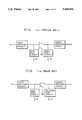
- FIG. 1(a)is a block diagram showing a typical prior art example of an amplifier using a field effect transistor (FET).
- FETfield effect transistor
- FIG. 1(b)is a block diagram showing a typical prior art example of an amplifier using a bipolar junction transistor (BJT).
- BJTbipolar junction transistor
- FIG. 1(c)is a block diagram showing a typical prior art example of a full Polar Feedback linearization System utilising exact high level power supply modulation.
- FIG. 2is a block diagram showing a typical prior art example of an envelope only Polar Feedback linearization System utilising exact high level power supply modulation.
- FIG. 3is a block diagram showing a typical prior art example of a Cartesian Feedback linearization System.
- FIG. 4is a block diagram showing the typical prior art example of an RF Feedback linearization System.
- FIG. 5is a block diagram showing the typical prior art example of an IF Feedback linearization System.
- FIG. 6is a block diagram showing the typical prior art example of a Feedforward linearization System.
- FIG. 7is a block diagram of the first preferred embodiment applied to a Cartesian Feedback linearization scheme where the envelope is obtained from the quadrature inputs.
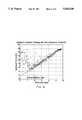
- FIG. 8is an example graph representing the optimum (based on best power-added efficiency) collector voltage with the base voltage fixed as a function of desired output levels.
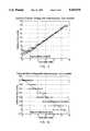
- FIG. 9is an example graph representing the optimum (based on best power-added efficiency) collector voltage with the base voltage variable in accordance with FIG. 10 as function of desired output levels.
- FIG. 10is an example graph representing the optimum (based on best power-added efficiency) base voltage with the collector voltage variable in accordance with FIG. 9 as function of desired output levels.
- FIG. 11is a block diagram of the second preferred embodiment applied to RF feedback linearization where the envelope is obtained by RF detection.
- FIG. 12is a block diagram of the third preferred embodiment applied to IF feedback linearization where the envelope is obtained by RF detection.
- FIG. 13is a block diagram of the forth preferred embodiment applied to a Feedforward linearization system where the envelope is obtained by RF detection.
- FIG. 14is a block diagram of other embodiments according to the present invention showing how the invention is applied genetically to any linearization scheme.
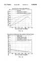
- FIG. 15is a graph showing the improvement in efficiency of the present invention under output power control.
- FIG. 16is a graph showing the improvement in intermodulation distortion and hence linearization effectiveness of the present invention under output power control for a two-tone test.
- FIG. 17is a graphical plot of a two-tone test after the application of linearization with a dynamically variable operating point at one output level.
- an efficient but non-linear RF amplifier 6has been utilised as the basis for this invention.
- This amplifiercan be based on a range of active devices such as BJTs,. FETs, and Valves. Typical examples of such amplifiers are shown in the prior art drawings of FIG. 1(a) and FIG. 1(b) showing a FET and BJT, respectively, along with associated elements. It can also be based on different classes of operation e.g Class AB, B, C, D, E or F and others.
- the preferred embodiments described hereare based on a BJT RF power amplifier with the operating class dependent on the base bias voltage.
- the non-linear amplifieris linearized so that the amplifier retains its inherent efficiency yet its distortion is sufficiently minimised.
- Other techniqueshave been employed to achieve a similar end. These techniques can be summarised as incorporating feedback, feedforward, or predistortion (fixed or adaptive) techniques.
- negative feedbackcan linearize non-linear systems.
- the negative feedbackcan be formed a number of ways, namely--at RF or IF, or at baseband in the form of Polar representation or Cartesian representation.
- Polar feedback 14utilises negative feedback of the baseband amplitude and phase of the signal to be amplified.
- the basic principleis shown in the prior art implementations of FIG. 1 and FIG. 2.
- the RF input signalis essentially broken up into two components, namely--amplitude and phase.
- a hard limiter 1obtains the phase information and an envelope detector 11 obtains the amplitude. These two signals then form the basis for the polar feedback loop.
- phaseis compared by a phase only sensitive detector formed by 1,2,3.
- the resultant phase differenceis then filtered by 4 and applied to a VCO (Voltage Controlled Oscillator) 5.
- VCOVoltage Controlled Oscillator
- This VCO signal(after suitable amplification) is large enough to drive the RF amplifier 6 to saturation thus ensuring efficient amplification.
- PLLPhase Locked Loop
- the envelope of the input obtained by 11is compared with the output by a subtracter 10.
- the resulting error signalis amplified and filtered by 12 which provides the necessary amplitude predistortion to the high level driver 13.
- the high level driver 13is normally intended to be highly efficient and usually incorporates switched-mode techniques.
- the amplitude feedback loopis closed by a signal obtained by envelope detector 9 which itself is driven by the RF coupler 7.
- the means by which the envelope is obtainedis not limited to simple envelope detection. Synchronous detection can be achieved by homodyning the RF signals with their hard-limited equivalents.
- the polar loophas the potential for high efficiency, the amplitude and phase signals have wide bandwidths (except perhaps AM systems) as a result of the non-linear relationship between these signals and the actual RF signal channel spectrum. Consequently, the polar loop components processing these signals must be capable of accommodating the larger bandwidths. Failing to do so minimises the linearization efficacy.
- the weakest link in regards to bandwidthis the driver. If it is to accommodate high bandwidth signals effectively and utilises switch-mode techniques, the switching frequency must be made high. A high switching frequency however results in greater switching losses and imposes a limit as to how high the switching frequency can be made. As will be shown, the present invention relaxes the need for the driver signal to track the envelope exactly and so provides superior linearization performance.
- the second prior art example of FIG. 2demonstrates amplitude-only feedback.
- Such a techniqueis applicable in systems where the AM-PM distortion is low and is generally not suitable for amplifiers using BJT's.
- this systemhas a hard limiter 15 to enable the RF amplifier 6 to be hard driven and hence to operate at high efficiency.
- This envelope feedback circuitryis the same as that of FIG. 1.
- An envelope detector 11obtains the envelope of the input which is compared to the output envelope by 10. After suitable gain and filtering 12 the resulting predistort drive is high level modulated by driver 13 and applied to the RF amplifier 6.
- the feedbackis obtained by an RF coupler 7 which allows the detector 9 to provide the feedback envelope signal necessary to close the loop.
- the amplitude only feedback techniquesuffers from the same bandwidth expansion problem described for FIG. 1. Amplitude-only. feedback is often used because of its simplicity.
- Cartesian Feedbackwhich uses negative feedback of the baseband quadrature modulation has been shown to provide excellent reduction in intermodulation distortion with low complexity and cost.
- Cartesian Feedback 33The basic principle of Cartesian Feedback 33 is depicted in the prior art drawing of FIG. 3.
- the forward path of the systemconsists of the main control loop gain and compensation filters 19,20 , a synchronous I-Q Modulator 21, a non-linear RF power amplifier 6 and the antenna 8 acting as the output load.
- the conventional I-Q modulator 21is comprised of two mixers 22, 24, a 90° phase splitter 23, and an RF combiner 25.
- the feedback pathobtains a portion of the transmitter output via an RF coupler 7, the signal from which is then synchronously demodulated 26.
- the resultant demodulated I-Q baseband signalsare used as the primary feedback signals and are subtracted 17-18 from the input.
- the resultant error signalsbecome the necessary pre-distort drive to linearize the non-linear RF power amplifier.
- the conventional I-Q demodulator 26is comprised of an RF splitter 30, two mixers 22, 24, and a 90° phase splitter 23.
- Synchronism between the modulator and demodulatoris obtained by splitting a common RF carrier 32. Due to differences in the forward and feedback paths a phase adjustor 31 is necessary to maintain the correct relationship between the input signals and feedback signals.
- Cartesian Feedback systemwhen properly assembled can give power added efficiencies of around 50% with a two-tone test coupled with excellent intermodulation distortion reduction. Further, by applying techniques to be described in the preferred embodiments, additional efficiency improvements can be achieved.
- RF feedback 38is shown in the prior art illustration of FIG. 4.
- This techniqueuses standard negative feedback of the actual RF signal.
- the input coupler 34allows the feedback to be subtracted from the RF input.
- the resulting error signalis then amplified by an amplifier 35.
- Feedback compensationis by way of a bandpass filter 36.
- the output coupler 7couples some of the output back through the feedback loss circuit 37 to complete the feedback loop.
- the feedback loss 37determines the overall gain of the linear amplifier and can actually be absorbed by the two couplers 34 and 7.
- the difficulty associated with RF feedbackis the practical implementation of the bandpass filter 36 which is usually extremely narrow at the RF operating frequency.
- IF feedback 48as shown in the prior art illustration of FIG. 5, overcomes the difficulty associated with the RF filter of the previous case by bringing the filter down to an IF frequency.
- the operation of IF feedbackis similar to RF feedback except IF conversion is utilised within the loop.
- the RF inputis first processed by a coupler 39 which provides the feedback connection from the output.
- the signalis then IF converted by a mixer 40 and passed through the IF bandpass compensation filter 41 and IF loop gain 42.
- the result from this processis an IF equivalent of the necessary RF prodistortion.
- This IF predistortion signalis reconverted to the RF frequency by a mixer 43 and RF bandpass filter 44 and then applied to the RF amplifier 6.
- the output from the amplifieris coupled by coupler 7 and fed-back to the input coupler 39 via the feedback loss network 45.
- the two remaining components in the figureprovide the local oscillator 47 and phase alignment 46 components necessary for the IF conversion process.
- RF feedforward system 55 of FIG. 6An alternative to the feedback systems described is the RF feedforward system 55 of FIG. 6.
- the RF inputis first split by a splitter 49.
- One arm of the splitterprovides the excitation signal for the RF amplifier 6.
- the output from tiffs amplifieris coupled 50 to a subtracter 53 which compares the amplifier's output with a time delayed 54 version of the input.
- the coupler 50is designed such that it provides a coupled loss roughly equivalent to the amplifier 6 gain.
- the time delay 54is also designed such that is roughly equivalent to the amplifier's 6 time delay.
- the result from the comparison 53represents the distortion generated by the amplifier 6. This distortion is amplified by the auxiliary linear power amplifier 52 for power combining by 7 to a delayed 51 version of the amplifier output.
- the combination by 7results in destructive cancellation of the RF amplifier 6 distortion provided the delay 51 matches the delay of the auxiliary amplifier 52.
- the matching of delays and gains/lossesis the main practical difficulty with this technique.
- the power consumption of the linear auxiliary amplifier 52results in the efficiency of the feedforward to be reduced. As will be shown, application of the present invention and making the main RF amplifier 7 more linear will require a smaller auxiliary amplifier 52 and so improve the overall efficiency.
- the source of excess power consumption in the linearization systems of FIGS. 3, 4, 5, and 6 discussed in this disclosurestems from the manner by which the desired RF envelope output level is achieved. Since these linearization schemes can only drive the input of the RF amplifier 6, it follows that the desired RF envelope output level is achieved by a change in the amplifier RF input drive level. Since in general, RF amplifiers operate more efficiently in saturated mode, the reductions in amplifier RF input drive levels result in the amplifier not operating at its peak efficiency. This is especially true at low output levels in the power control range. It is therefore advantageous to maintain the amplifier RF input drive at a level which achieves the highest power added efficiency. With this constraint however, the necessary envelope level modulation must be obtained via other means.
- the means adopted in accordance with the present inventionis by way of high level power supply modulation 57 of the RF amplifier 6 with or without base-(or gate) bias modulation 58 or by having a fixed power supply voltage with a variable base or gate bias modulation 58.
- FIG. 7is a drawing of the first preferred embodiment and illustrates how this invention functions as applied to Cartesian feedback.
- the standard Cartesian feedback loopis represented by 33.
- 61represents the additional components which give the added efficiency improvements to the Cartesian Feedback System.
- This circuitessentially determines the envelope "R" from I and Q, from the simple pythagorean equation: ##EQU1##
- the envelope determining circuit means 56may range from a DSP circuit where "R" can be obtained via calculation or look-up table, to an analog computing circuit or even an RF envelope detecting circuit 62 (FIGS. 11-14).
- FIG. 8shows the optimum (for the best power added efficiency, Nadd) collector voltage of a BJT based RF power amplifier with the base voltage fixed to zero.
- FIGS. 9 and 10present the optimum (for the best power added efficiency, Nadd) collector and base voltages when both are varied.
- the straight-line approximation given by these graphsform the basis of the maps.
- the circular dotsare the actual measurement data showing the measurement uncertainty.
- the resultant signals from these functionsis then applied to the RF power amplifier by power supply drivers 59,60.
- These drivers used in accordance with the present inventionmay utilise a switched mode power supply for 59, although other electronic embodiments such as resonant, semi-resonant, or multi-resonant supply converters, Class D modulators etc. could be utilised, and a linear driver for 60. It is also possible due to the toleration of the high level power supply modulation inexactness, to switch in different power supply rails for 59.
- the signal delay through the dynamic bias circuitsis different to that of the linearization circuitry. Consequently, it is possible to improve the operation of the dynamic bias circuits by introducing delay blocks 66a and 66b to equalise the difference in the signal paths. It must be stated that these delay blocks are optional and that the preferred embodiments of the invention described in this disclosure encompass both embodiments with the delay blocks of 66a and 66b and embodiments without the delay blocks of 66a and 66b. Also, if delay is to be equalised, only one delay block is generally required. That delay block is added in the signal path which offers the smallest delay so that the overall delay in that signal path is brought up to the delay of the other larger delay signal path.
- FIG. 11shows the application of the dynamic bias circuitry 61 to the RF feedback linearization 38.
- the only difference between the operation of the Cartesian system of FIG. 7is the manner by which "R" is obtained by an envelope detection circuit 62.
- the improvements in efficiency obtained with this systemstem from the same reasons as discussed previously--that is, the dynamic bias circuitry 61 selects the best operating bias for a given output signal and the RF feedback adjusts the input predistortion to the amplifier to achieve exact linearization.
- FIG. 12is a block diagram which demonstrates the third embodiment as applied to IF feedback. Again the operation and efficiency improvements given by the dynamic bias circuitry 61 is the same as the previous embodiments.
- the fourth preferred embodiment of the invention as applied to an amplifier with feed forwardis shown in FIG. 13.
- the dynamic bias circuitry 61is applied to the RF amplifier 6 as with the previous embodiment.
- the advantage of the dynamic bias circuitry 61 as applied to feedforward linearization 85stems both from the improvement in efficiency of the main RF amplifier 6 and also the linearization of the RF amplifier 6. Since the RF amplifier is made less non-linear by the application of 61, the auxiliary linear amplifier 52 can be made smaller and so consume less power. Consequently the efficiency of the overall feedforward system is improved.
- FIG. 14illustrates other embodiments according to the present invention.
- the linearization schemeis shown as a genetic block 63 which can utilise both feedback and feedforward control to linearize the RF amplifier 6 by application of a predistorting drive signal to the RF amplifier and/or by addition 65 of a distortion cancelling signal at the output.
- a coupling means 64is provided by which the feedback signal can be obtained.
- the dynamic bias circuitry 61is applied to the RF amplifier's bias and supply lines. By forcing these lines to a level known to give the best operating efficiency by MAPs 57,58 the linearization automatically adopts the necessary state to maintain exact linearization.
- FIGS. 15, 16 and 17show two-tone output power in dBm.
- FIG. 15shows the improvement in power-added efficiency (Nadd) compared to a fixed collector (or drain) voltage with ideal tracking of the mapping functions. Both collector only and collector and base modulation show significant improvements in efficiency particularly at low power levels.
- FIG. 14shows the linearization effectiveness of the invention by plotting worst-case intermodulation distortion product (IMW) versus two-tone output power. The introduction of collector only modulation actually results in a minor increase in intermodulation products.
- IMWintermodulation distortion product
- FIG. 17shows a typical closed-loop spectral plot of a two-tone test at a power output level of 25.25 dBm with both the collector and base being driven by mapping functions 57, 58.
- the improvement in intermodulation performance delivered by the present inventioncan be exchanged for extra bandwidth or stability in feedback linearization systems.
- the modulation circuits 59 and 40do not have to be exact. This is because the linearization scheme is able to modify the input drive signals slightly to achieve the exact desired output.
- the inventioncan therefore tolerate ripple in a switch-mode driver 59 which can also have in-band frequency components.
- the linearization correctionapplies to the ripple of the power supply driver in addition to the AM-to-AM and AM-to-PM distortions of the non-linear amplifier 6 and hence is an improvement over other systems (such as Koch and Fisher etc.) which utilise envelope feedback only.
Landscapes
- Engineering & Computer Science (AREA)
- Power Engineering (AREA)
- Physics & Mathematics (AREA)
- Nonlinear Science (AREA)
- Computer Networks & Wireless Communication (AREA)
- Signal Processing (AREA)
- Amplifiers (AREA)
Abstract
Description
This invention relates to the improved linearization of non-linear amplifiers for the purposes of efficient Radio Frequency (RF) power amplification of any RF signals containing amplitude or amplitude and phase modulation.
Increasing demand for mobile and personal communication services has renewed interest in spectrally efficient modulation schemes. Since the most efficient forms of RF power amplification are non-linear, CPM (Continuous Phase Modulation) schemes have been preferred for portable wireless applications (e.g Gaussian Minimum Shift Keying--GMSK). Because of growing pressures for extra capacity however, the advantages of retaining a constant envelope are giving way to linear modulation (e.g π/4 Shift DQPSK).
Although the filtering applied in linear modulation schemes generally produces gains in spectrum utilisation, envelope variations are also introduced. Such signals when passed through non-linear RF amplifiers undergo distortion (Amplitude-to-Amplitude Modulation & Amplitude-to-Phase Modulation [AM/AM & AM/PM]) which results in a spreading of the spectrum beyond the allocated channel and reduced performance. The inefficiency of conventional linear RF amplifiers (e.g Class A operated under appropriate back-off) would have a disastrous effect on the battery life of portable wireless transmitting equipment. Improvements in RF amplifier efficiency would directly lead to improvements in the talk-time, recharging intervals, and size and weight of the overall wireless unit. The ideal amplifier for linear modulated portable systems is therefore a linear amplifier which is also power efficient.
Because linear amplifiers can amplify signals with any combination of amplitude and phase modulation, the choice of modulation scheme is not limited by the transmitter and hence can be software selectable. This is advantageous in military applications, and in commercial applications crossing international borders and standards. Other applications for linear amplification include various digital cellular and Private Mobile Radio (PMR) systems, traditional Amplitude Modulation (AM) and Single Side-Band (SSB) systems, and instances where transmitter turn-on is to be well controlled such as bandlimited pulse systems found in radar and paging applications and in Time Division Multiple Access (TDMA) systems. Linear Amplifiers can also accommodate the envelope variations caused by the combination of multiple signals such as those found in multicarrier basestations.
Feedforward linearization is one way non-linear but efficient amplifiers can be linearized. It is based on cancelling the distortion of the amplifier at the output. The distortion or error signal is measured by comparing the amplifier output signal with the input. After suitable scaling and delay matching this error signal, which is out of phase with the distortion, is applied to the output resulting in a reduction in the distortion. The error signal must be amplified by a linear RF power amplifier however. This results in a compromise since in general, as the efficiency of an RF power amplifier increases, so does its distortion and hence the error signal level to be amplified by the linear amplifier. The larger the error signal level the larger the linear amplifier and hence the greater the power consumption and the lower the efficiency. Such systems have been applied particularly for wideband linearization schemes. A typical example is disclosed by P. B. Kenington, M. A. Beach, A. Bateman and J. P. McGeehan in PCT Pat. No. WO 91/16760.
It has long been known that feedback can linearize non-linear systems. Cartesian Feedback for example, which uses negative feedback of the baseband quadrature modulation provides excellent reduction in intermodulation distortion with low complexity and cost. A typical example of what is achievable with cartesian feedback is given in by M. Johannson and T. Mattsson, "Transmitter Linearization using Cartesian Feedback for Linear TDMA Modulation", in the proceedings of the 41st IEEE Vehicular Technology Conference, St. Louis, USA, VTC-91, pp 439-444, May, 1991. Other typical feedback techniques include Polar Feedback discussed in U.S. Pat. No. 5,023,937; IF (Intermediate Frequency) Feedback demonstrated by K. G. Voyce and J. H. McCandless, "Power Amplifier Linearization Using IF Feedback", in the IEEE MTT-S digest, pp 863-866, 1989; and RF Feedback demonstrated by H. A. Rosen and A. T. Owens, "Power Amplifier Linearity Studies for SSB Transmissions", IEEE Transactions on Communications Systems, pp 150-159, June, 1964.
High level modulation of the power supply of an RF power amplifier, for the purposes of amplitude (or envelope) modulation, is a well established technique which provides good power efficiency when combined with efficient high level power supply modulators. This is the basis for amplitude feedback only techniques of EP Pat. No. 431201 FIG. 19 (also WO 9100653); of U.S. Pat. No. 3,900,823 FIGS. 1 and 2; of K. Chiba, To Nojima and S. Tomisato, "Linearized Saturation Amplifier with Bidirectional Control for Digital Mobile Radio", in the proceedings of Globecomm (IEEE), pp 1958-1962, 1990; and of M. J. Koch and R. E. Fisher, "A High Efficiency 835MHz Linear Power Amplifier for Digital Cellular Telephony", in the proceedings of the 39th IEEE Vehicular Technology Conference, USA, VTC89, pp 17-18, May, 1989. The problem with these systems is the relatively larger bandwidths of the amplitude signals compared with corresponding baseband quadrature modulation and the inability to control AM-PM distortion. Consequently the spectral control is generally inferior to that of Cartesian Feedback, IF Feedback and RF Feedback. Full Polar Feedback (both Amplitude and Phase feedback) overcomes the limitation of the inability to control AM-PM distortion, but still suffers from the bandwidth expansion problem on both the amplitude and phase signals.
Dynamic control of the DC gate bias has also been shown to improve amplifier efficiency by A. A. M. Saleh and D. C. Cox, "Improving the Power-Added Efficiency of FET Amplifiers Operating with Varying Envelope Signals", IEEE Transactions on Microwave Theory and Techniques, Vol. 31, January 1983. U.S. Pat. No. 4631491 also demonstrates that feedback can be used to control the collector and base bias in a Bipolar Junction Transistor based RF amplifier to improve the efficiency of the amplifier.
From the foregoing, it will be appreciated that it is desirable to linearize a non-linear RF power amplifier with the object of improving the linearity of an RF power amplifier and thus reducing its intermodulation distortion products and to do so with a high level of power efficiency.
According to a broad aspect of the invention, there is provided a linearized power amplifier comprising a non-linear radio frequency (RF) power amplifier, dynamic bias modulation means for modulating an operating point of the RF amplifier, and linearization means, such as Cartesian Feedback, IF Feedback, RF Feedback or Feedforward, for linearizing the RF amplifier.
Preferably, the dynamic bias modulation means includes envelope generating means for producing an envelope signal representing the envelope of the RF signals, and signal processing means for processing the envelope signal whereby an optimum operating voltage, such as the power supply voltage and/or the base or gate bias voltage, for the RF amplifier is selected for the desired RF output envelope level. The power supply voltage and/or the base or gate voltage of the RF amplifier is preferably modulated by power driver means in accordance with power bias signals and/or base or gate bias signals generated by the signal processing means.
Preferably, there is also provided delay means equalising the delay between the dynamic bias modulation means and the linearization means.
The signal processing means preferably comprises memory means including predetermined data computed from measured characteristics of the amplifier or a simplified transfer function determined from the measured characteristics of the amplifier, and means for producing a power bias signal and/or a base or gate bias signal representing the optimum bias voltage corresponding to the envelope signal from the envelope generating means. The signal processing means can thus optimise the operation of the RF power amplifier at its most efficient point for the required instantaneous output power.
According to another aspect of the present invention there is provided dynamic bias modulation means for modulating an operating point of an RF amplifier comprising: envelope generating means for producing an envelope signal representing the envelope of the RF signals: signal processing means for processing the envelope signal including memory means containing predetermined data computed from measured characteristics of the amplifier, and dynamic bias means for producing dynamic bias modulation signals each of which represents an optimum operating voltage for the RF amplifier corresponding to an instantaneous envelope signal received from the envelope generating means; and power driver means for modulating an operating voltage of the RF amplifier such as power supply voltage and/or the base or gate bias voltage in response to power bias and/or bias signals from the signal processing means.
According to a further aspect of the invention there is provided a method of improving the efficiency of a linearized radio frequency (RF) power amplifier comprising the steps of: measuring the characteristics of the RF amplifier, generating envelope signals representing the envelope of the RF input signal to the RF amplifier, processing the envelope signals in accordance with the measured characteristics of the RF amplifier to produce bias signals corresponding to optimum operating voltages for the desired RF output envelope, and dynamically modulating the operating voltage of the RF amplifier in response to said bias signals.
Dynamic variation or modulation of an operating point of the RF amplifier may broadly be referred to as "dynamic bias". For example, with Bipolar Junction Transistor (BJT) based R.F power amplifiers, dynamic bias encompasses variation in collector and/or base voltages. For Field Effect Transistor (FET) based RF power amplifiers, the variation in operating point is achieved by drain and/or gate bias modulation. Dynamic bias may be referred to as "high level power supply modulation" which refers to modulation of the collector for a BJT amplifier, the drain of an FET amplifier, the anode of valves and so on. One form of dynamic bias also refers to the bias control of other active amplification devices such as the family of Field Effect Transistors FET's) (including Junction FETs, Metal Oxide Silicon FETs, GAsFETs etc.) and thermo-ionic devices such as triodes and other valves and Travelling Wave Tube Amplifiers. Further reference to dynamic bias will refer to any of these devices.
High level power supply modulation without base or gate bias, and dynamic base or gate bias modulation in an amplifier having a substantially fixed power supply have both been found to increase the efficiency of an RF power amplifier with linearization means such as Cartesian, IF or RF Feedback or Feedforward systems. Each of these bias modulation systems are therefore included within the scope of this invention.
However, in a preferred embodiment of the present invention, a linearized RF amplifier incorporates both high level power supply modulation means, such as collector or drain modulation, for modulating the power supply voltage of the RF amplifier and base or gate bias modulation means for modulating the base or gate bias voltage of the RF amplifier. With the right combination of power supply and base or gate bias modulation, it is possible to maximise efficiency improvements for a given output power of the RF amplifier. Moreover, the combination of linearization means, such as Cartesian, IF or RF Feedback or Feedforward, and high level power supply or dynamic bias modulation gives the benefits of excellent spectral control and intermodulation distortion reduction of the linearization scheme coupled with high efficiency. Furthermore, a means of accurate power control is provided as well as a relaxation in the power supply modulator requirements compared to those utilized in polar feedback systems.
The novelty and distinct advantages-of the present invention will become apparent to those skilled in the art by reading the following specification and by reference to the drawings in which:
FIG. 1(a) is a block diagram showing a typical prior art example of an amplifier using a field effect transistor (FET).
FIG. 1(b) is a block diagram showing a typical prior art example of an amplifier using a bipolar junction transistor (BJT).
FIG. 1(c) is a block diagram showing a typical prior art example of a full Polar Feedback linearization System utilising exact high level power supply modulation.
FIG. 2 is a block diagram showing a typical prior art example of an envelope only Polar Feedback linearization System utilising exact high level power supply modulation.
FIG. 3 is a block diagram showing a typical prior art example of a Cartesian Feedback linearization System.
FIG. 4 is a block diagram showing the typical prior art example of an RF Feedback linearization System.
FIG. 5 is a block diagram showing the typical prior art example of an IF Feedback linearization System.
FIG. 6 is a block diagram showing the typical prior art example of a Feedforward linearization System.
FIG. 7 is a block diagram of the first preferred embodiment applied to a Cartesian Feedback linearization scheme where the envelope is obtained from the quadrature inputs.
FIG. 8 is an example graph representing the optimum (based on best power-added efficiency) collector voltage with the base voltage fixed as a function of desired output levels.
FIG. 9 is an example graph representing the optimum (based on best power-added efficiency) collector voltage with the base voltage variable in accordance with FIG. 10 as function of desired output levels.
FIG. 10 is an example graph representing the optimum (based on best power-added efficiency) base voltage with the collector voltage variable in accordance with FIG. 9 as function of desired output levels.
FIG. 11 is a block diagram of the second preferred embodiment applied to RF feedback linearization where the envelope is obtained by RF detection.
FIG. 12 is a block diagram of the third preferred embodiment applied to IF feedback linearization where the envelope is obtained by RF detection.
FIG. 13 is a block diagram of the forth preferred embodiment applied to a Feedforward linearization system where the envelope is obtained by RF detection.
FIG. 14 is a block diagram of other embodiments according to the present invention showing how the invention is applied genetically to any linearization scheme.
FIG. 15 is a graph showing the improvement in efficiency of the present invention under output power control.
FIG. 16 is a graph showing the improvement in intermodulation distortion and hence linearization effectiveness of the present invention under output power control for a two-tone test.
FIG. 17 is a graphical plot of a two-tone test after the application of linearization with a dynamically variable operating point at one output level.
The detailed description set forth below in connection with the appended drawings is intended merely as a description of the presently preferred embodiments of the invention, and is not intended to represent the only form in which the present invention may be constructed or utilised (e.g the use of FETs or valves instead of BJT active devices). The description describes the implementation of the invention only in connection with the illustrated embodiments. It is to be understood, however, that the implementation of the invention can be accomplished by different electronic embodiments and it is intended these be encompassed within the spirit and scope of the invention.
In order to achieve the objective of efficient linear RF amplification an efficient butnon-linear RF amplifier 6 has been utilised as the basis for this invention. This amplifier can be based on a range of active devices such as BJTs,. FETs, and Valves. Typical examples of such amplifiers are shown in the prior art drawings of FIG. 1(a) and FIG. 1(b) showing a FET and BJT, respectively, along with associated elements. It can also be based on different classes of operation e.g Class AB, B, C, D, E or F and others. The preferred embodiments described here are based on a BJT RF power amplifier with the operating class dependent on the base bias voltage.
Through the application of the described techniques contained in the description of the preferred embodiments of the present invention, the non-linear amplifier is linearized so that the amplifier retains its inherent efficiency yet its distortion is sufficiently minimised. Other techniques have been employed to achieve a similar end. These techniques can be summarised as incorporating feedback, feedforward, or predistortion (fixed or adaptive) techniques.
It has long been known that negative feedback can linearize non-linear systems. To linearize RF amplifiers, the negative feedback can be formed a number of ways, namely--at RF or IF, or at baseband in the form of Polar representation or Cartesian representation.
The phase is compared by a phase only sensitive detector formed by 1,2,3. The resultant phase difference is then filtered by 4 and applied to a VCO (Voltage Controlled Oscillator) 5. This VCO signal (after suitable amplification) is large enough to drive theRF amplifier 6 to saturation thus ensuring efficient amplification. To complete the phase feedback loop some of the signal is tapped off by anRF coupler 7 and is fed-back to thephase detector 3. This closed loop phase feedback is commonly referred to as a PLL (Phase Locked Loop).
The envelope of the input obtained by 11 is compared with the output by asubtracter 10. The resulting error signal is amplified and filtered by 12 which provides the necessary amplitude predistortion to thehigh level driver 13. Thehigh level driver 13 is normally intended to be highly efficient and usually incorporates switched-mode techniques. The amplitude feedback loop is closed by a signal obtained by envelope detector 9 which itself is driven by theRF coupler 7. The means by which the envelope is obtained is not limited to simple envelope detection. Synchronous detection can be achieved by homodyning the RF signals with their hard-limited equivalents.
Although the polar loop has the potential for high efficiency, the amplitude and phase signals have wide bandwidths (except perhaps AM systems) as a result of the non-linear relationship between these signals and the actual RF signal channel spectrum. Consequently, the polar loop components processing these signals must be capable of accommodating the larger bandwidths. Failing to do so minimises the linearization efficacy. The weakest link in regards to bandwidth is the driver. If it is to accommodate high bandwidth signals effectively and utilises switch-mode techniques, the switching frequency must be made high. A high switching frequency however results in greater switching losses and imposes a limit as to how high the switching frequency can be made. As will be shown, the present invention relaxes the need for the driver signal to track the envelope exactly and so provides superior linearization performance.
The second prior art example of FIG. 2 demonstrates amplitude-only feedback. Such a technique is applicable in systems where the AM-PM distortion is low and is generally not suitable for amplifiers using BJT's. In common with the previous prior art example of FIG. 1, this system has ahard limiter 15 to enable theRF amplifier 6 to be hard driven and hence to operate at high efficiency. This envelope feedback circuitry is the same as that of FIG. 1. Anenvelope detector 11 obtains the envelope of the input which is compared to the output envelope by 10. After suitable gain andfiltering 12 the resulting predistort drive is high level modulated bydriver 13 and applied to theRF amplifier 6. The feedback is obtained by anRF coupler 7 which allows the detector 9 to provide the feedback envelope signal necessary to close the loop. The amplitude only feedback technique suffers from the same bandwidth expansion problem described for FIG. 1. Amplitude-only. feedback is often used because of its simplicity.
Cartesian Feedback which uses negative feedback of the baseband quadrature modulation has been shown to provide excellent reduction in intermodulation distortion with low complexity and cost.
The basic principle ofCartesian Feedback 33 is depicted in the prior art drawing of FIG. 3. The baseband inputs to the system in quadrature format--which are often termed I and Q or cartesian components, form the reference signals for the loop. The forward path of the system consists of the main control loop gain andcompensation filters synchronous I-Q Modulator 21, a non-linearRF power amplifier 6 and theantenna 8 acting as the output load.
Theconventional I-Q modulator 21 is comprised of twomixers phase splitter 23, and anRF combiner 25.
The feedback path obtains a portion of the transmitter output via anRF coupler 7, the signal from which is then synchronously demodulated 26. The resultant demodulated I-Q baseband signals are used as the primary feedback signals and are subtracted 17-18 from the input. The resultant error signals become the necessary pre-distort drive to linearize the non-linear RF power amplifier.
Theconventional I-Q demodulator 26 is comprised of anRF splitter 30, twomixers phase splitter 23.
Synchronism between the modulator and demodulator is obtained by splitting acommon RF carrier 32. Due to differences in the forward and feedback paths aphase adjustor 31 is necessary to maintain the correct relationship between the input signals and feedback signals.
The Cartesian Feedback system when properly assembled can give power added efficiencies of around 50% with a two-tone test coupled with excellent intermodulation distortion reduction. Further, by applying techniques to be described in the preferred embodiments, additional efficiency improvements can be achieved.
IFfeedback 48 as shown in the prior art illustration of FIG. 5, overcomes the difficulty associated with the RF filter of the previous case by bringing the filter down to an IF frequency. The operation of IF feedback is similar to RF feedback except IF conversion is utilised within the loop. The RF input is first processed by acoupler 39 which provides the feedback connection from the output. The signal is then IF converted by amixer 40 and passed through the IFbandpass compensation filter 41 and IFloop gain 42. The result from this process is an IF equivalent of the necessary RF prodistortion. This IF predistortion signal is reconverted to the RF frequency by amixer 43 andRF bandpass filter 44 and then applied to theRF amplifier 6. The output from the amplifier is coupled bycoupler 7 and fed-back to theinput coupler 39 via thefeedback loss network 45. The two remaining components in the figure provide thelocal oscillator 47 andphase alignment 46 components necessary for the IF conversion process.
An alternative to the feedback systems described is theRF feedforward system 55 of FIG. 6. In this prior art example the RF input is first split by asplitter 49. One arm of the splitter provides the excitation signal for theRF amplifier 6. The output from tiffs amplifier is coupled 50 to asubtracter 53 which compares the amplifier's output with a time delayed 54 version of the input. Thecoupler 50 is designed such that it provides a coupled loss roughly equivalent to theamplifier 6 gain. Thetime delay 54 is also designed such that is roughly equivalent to the amplifier's 6 time delay. The result from thecomparison 53 represents the distortion generated by theamplifier 6. This distortion is amplified by the auxiliarylinear power amplifier 52 for power combining by 7 to a delayed 51 version of the amplifier output. The combination by 7 results in destructive cancellation of theRF amplifier 6 distortion provided thedelay 51 matches the delay of theauxiliary amplifier 52. The matching of delays and gains/losses is the main practical difficulty with this technique. The power consumption of the linearauxiliary amplifier 52 results in the efficiency of the feedforward to be reduced. As will be shown, application of the present invention and making themain RF amplifier 7 more linear will require a smallerauxiliary amplifier 52 and so improve the overall efficiency.
The source of excess power consumption in the linearization systems of FIGS. 3, 4, 5, and 6 discussed in this disclosure stems from the manner by which the desired RF envelope output level is achieved. Since these linearization schemes can only drive the input of theRF amplifier 6, it follows that the desired RF envelope output level is achieved by a change in the amplifier RF input drive level. Since in general, RF amplifiers operate more efficiently in saturated mode, the reductions in amplifier RF input drive levels result in the amplifier not operating at its peak efficiency. This is especially true at low output levels in the power control range. It is therefore advantageous to maintain the amplifier RF input drive at a level which achieves the highest power added efficiency. With this constraint however, the necessary envelope level modulation must be obtained via other means. The means adopted in accordance with the present invention is by way of high levelpower supply modulation 57 of theRF amplifier 6 with or without base-(or gate)bias modulation 58 or by having a fixed power supply voltage with a variable base orgate bias modulation 58.
FIG. 7 is a drawing of the first preferred embodiment and illustrates how this invention functions as applied to Cartesian feedback. The standard Cartesian feedback loop is represented by 33. 61 represents the additional components which give the added efficiency improvements to the Cartesian Feedback System.
First the quadrature input signals are applied to anenvelope determining circuit 56. This circuit essentially determines the envelope "R" from I and Q, from the simple pythagorean equation: ##EQU1##
The envelope determining circuit means 56 may range from a DSP circuit where "R" can be obtained via calculation or look-up table, to an analog computing circuit or even an RF envelope detecting circuit 62 (FIGS. 11-14).
Once the "R" signal is obtained it is modified byfunctions MAP C 57 andMAP B 58. The results of such a process are shown in FIG. 8, FIG. 9 and FIG. 10. FIG. 8 shows the optimum (for the best power added efficiency, Nadd) collector voltage of a BJT based RF power amplifier with the base voltage fixed to zero. FIGS. 9 and 10 present the optimum (for the best power added efficiency, Nadd) collector and base voltages when both are varied. The straight-line approximation given by these graphs form the basis of the maps. The circular dots are the actual measurement data showing the measurement uncertainty.
These functions could again be built using DSP techniques (and indeed included in the "R" calculating circuit) or by a simple analog approximation. The "R" calculating circuit could also be simplified by calculating "R2 " or some other function of R, and using this signal to drive the mapping functions 57,58 instead of "R".
The resultant signals from these functions is then applied to the RF power amplifier bypower supply drivers
In general, the signal delay through the dynamic bias circuits is different to that of the linearization circuitry. Consequently, it is possible to improve the operation of the dynamic bias circuits by introducingdelay blocks
The second preferred embodiment FIG. 11 shows the application of thedynamic bias circuitry 61 to theRF feedback linearization 38. The only difference between the operation of the Cartesian system of FIG. 7 is the manner by which "R" is obtained by anenvelope detection circuit 62. The improvements in efficiency obtained with this system stem from the same reasons as discussed previously--that is, thedynamic bias circuitry 61 selects the best operating bias for a given output signal and the RF feedback adjusts the input predistortion to the amplifier to achieve exact linearization.
FIG. 12 is a block diagram which demonstrates the third embodiment as applied to IF feedback. Again the operation and efficiency improvements given by thedynamic bias circuitry 61 is the same as the previous embodiments.
The fourth preferred embodiment of the invention as applied to an amplifier with feed forward is shown in FIG. 13. Thedynamic bias circuitry 61 is applied to theRF amplifier 6 as with the previous embodiment. The advantage of thedynamic bias circuitry 61 as applied to feedforward linearization 85 stems both from the improvement in efficiency of themain RF amplifier 6 and also the linearization of theRF amplifier 6. Since the RF amplifier is made less non-linear by the application of 61, the auxiliarylinear amplifier 52 can be made smaller and so consume less power. Consequently the efficiency of the overall feedforward system is improved.
FIG. 14 illustrates other embodiments according to the present invention. The linearization scheme is shown as agenetic block 63 which can utilise both feedback and feedforward control to linearize theRF amplifier 6 by application of a predistorting drive signal to the RF amplifier and/or byaddition 65 of a distortion cancelling signal at the output. A coupling means 64 is provided by which the feedback signal can be obtained.
As shown with the previous embodiments, thedynamic bias circuitry 61 is applied to the RF amplifier's bias and supply lines. By forcing these lines to a level known to give the best operating efficiency byMAPs
The advantages of this invention are demonstrated in FIGS. 15, 16 and 17. The X-axes of FIGS. 15 and 16 show two-tone output power in dBm. FIG. 15 shows the improvement in power-added efficiency (Nadd) compared to a fixed collector (or drain) voltage with ideal tracking of the mapping functions. Both collector only and collector and base modulation show significant improvements in efficiency particularly at low power levels. FIG. 14 shows the linearization effectiveness of the invention by plotting worst-case intermodulation distortion product (IMW) versus two-tone output power. The introduction of collector only modulation actually results in a minor increase in intermodulation products. Under collector and base control however, the improvement in intermodulation distortion indicates the techniques disclosed herein result in an improvement in the linearization efficacy in addition to a substantial improvement in the power-added efficiency of the amplifier. FIG. 17 shows a typical closed-loop spectral plot of a two-tone test at a power output level of 25.25 dBm with both the collector and base being driven bymapping functions
The improvement in intermodulation performance delivered by the present invention can be exchanged for extra bandwidth or stability in feedback linearization systems.
Since the power supply modulation is not used entirely for linearization purposes as in U.S. Pat. No. 4,631,491 themodulation circuits mode driver 59 which can also have in-band frequency components. The linearization correction applies to the ripple of the power supply driver in addition to the AM-to-AM and AM-to-PM distortions of thenon-linear amplifier 6 and hence is an improvement over other systems (such as Koch and Fisher etc.) which utilise envelope feedback only.
Claims (17)
1. A linearized power amplifier circuit comprising:
a non-linear radio frequency (RF) power amplifier for amplifying an input signal and producing an output signal corresponding thereto, said input signal having envelope properties, said non-linear amplifier exhibiting non-linear amplitude and phase characteristics and having at least one operating point input;
dynamic bias modulation means for dynamically modulating the operation of said non-linear amplifier for efficient operation of said non-linear amplifier, said dynamic bias modulation means comprising, an input signal envelope determining means for obtaining an envelope signal from said input signal, mapping means for converting said envelope signal to at least one optimum operating voltage for said non-linear amplifier, and power driver means for applying said at least one operating voltage to said operating point input of said non-linear amplifier; and
linearization means which is separate and distinct from said dynamic bias modulation means, said linearization means utilizing a signal representation in said circuit that does not result in bandwidth expansion for linearizing and correcting for the non-linear amplitude and phase characteristics of said non-linear amplifier and further for correcting for additional distortion and errors introduced by said dynamic bias modulation means.
2. A linearized power amplifier circuit according to claim 1 wherein said non-linear amplifier has a pair of operating point inputs which comprise a power supply input and a bias port.
3. A linearized power amplifier circuit according to claim 2 wherein said mapping means of said dynamic bias modulation means converts said envelope signal to a power supply operating voltage and a bias port operating voltage, and said power driver means comprises a first power driver for applying said power supply operating voltage to said power supply input of said non-linear amplifier and a second power driver for applying said bias port operating voltage to said bias port.
4. A linearized power amplifier circuit according to claim 3 wherein said mapping means of said dynamic bias modulation means utilizes predetermined amplifier efficiency measurements which are obtained by finding optimum power supply and bias port operating voltages for best efficiency.
5. A linearized power amplifier circuit according to claim 2 wherein said non-linear amplifier comprises a bipolar junction transistor (BJT) having collector and base elements, and wherein said power supply input is coupled to the collector of said BJT, and said bias port is coupled to the base of said BJT.
6. A linearized power amplifier circuit according to claim 2 wherein said non-linear amplifier comprises a field effect transistor (FET) having drain and gate elements, and wherein said power supply input is coupled to the drain of said FET, and said bias port is coupled to the gate of said FET.
7. A linearized power amplifier circuit according to claim 2 wherein said dynamic bias modulation means applies said optimum operating voltage only to said power supply input and not to said bias port of said non-linear amplifier.
8. A linearized power amplifier circuit according to claim 2 wherein said dynamic bias modulation means applies said optimum operating voltage only to said bias port and not to the power supply input of said non-linear amplifier.
9. A linearized power amplifier circuit according to claim 1 wherein said dynamic bias modulation means includes a time delay means for delaying said input signal to improve the efficiency of said dynamic bias modulation means.
10. A linearized power amplifier circuit according to claim 1 wherein said mapping means of said dynamic bias modulation means comprises signal processing means which utilizes predetermined amplifier efficiency measurements to map envelope signals to said at least one optimum operating voltage.
11. A linearized power amplifier circuit according to claim 1 wherein said mapping means of said dynamic bias modulation means employs a simplified transfer function of predetermined amplifier efficiency measurements to map envelope signals to said at least one optimum operating voltage.
12. A linearized power amplifier according to claim 1 wherein said power driver means is formed and constructed for applying said at least one operating voltage to said operating point input of said non-linear amplifier in an efficient but not necessarily accurate manner.
13. A linearized power amplifier circuit according to claim 1 wherein said linearization means comprises of a Cartesian feedback linearization circuit.
14. A linearized power amplifier circuit according to claim 1 wherein said linearization means comprises of a RF feedback-linearization circuit.
15. A linearized power amplifier circuit according to claim 1 wherein said linearization means comprises of an intermediate frequency (IF) feedback linearization circuit.
16. A linearized power amplifier circuit according to claim 1 wherein said linearization means comprises of a feedforward linearization circuit.
17. A linearized power amplifier circuit according to claim 1 wherein said linearization means processes said input signal and includes a delay means for delaying said input signal being processed by said linearization means so it arrives at said non-linear amplifier in a manner which, when combined with said optimum operating point voltage provided by said dynamic bias modulation means, results in improved efficiency.
Applications Claiming Priority (2)
| Application Number | Priority Date | Filing Date | Title |
|---|---|---|---|
| AUPL7828 | 1993-03-16 | ||
| AUPL782893 | 1993-03-16 |
Publications (1)
| Publication Number | Publication Date |
|---|---|
| US5420536Atrue US5420536A (en) | 1995-05-30 |
Family
ID=3776780
Family Applications (1)
| Application Number | Title | Priority Date | Filing Date |
|---|---|---|---|
| US08/212,946Expired - LifetimeUS5420536A (en) | 1993-03-16 | 1994-03-15 | Linearized power amplifier |
Country Status (1)
| Country | Link |
|---|---|
| US (1) | US5420536A (en) |
Cited By (186)
| Publication number | Priority date | Publication date | Assignee | Title |
|---|---|---|---|---|
| WO1996039780A1 (en)* | 1995-06-05 | 1996-12-12 | The Chamberlain Group, Inc. | Radio frequency transmitter having switched mode power supply |
| US5694431A (en)* | 1996-01-17 | 1997-12-02 | Motorola, Inc. | Method and apparatus for average power control |
| US5705949A (en)* | 1996-09-13 | 1998-01-06 | U.S. Robotics Access Corp. | Compensation method for I/Q channel imbalance errors |
| US5732333A (en)* | 1996-02-14 | 1998-03-24 | Glenayre Electronics, Inc. | Linear transmitter using predistortion |
| US5880633A (en)* | 1997-05-08 | 1999-03-09 | Motorola, Inc. | High efficiency power amplifier |
| FR2769152A1 (en)* | 1997-09-30 | 1999-04-02 | Motorola Inc | PRELIMINARY DEFORMATION SYSTEM AND METHOD OF USING AN ANALOGUE FEEDBACK LOOP FOR THE ADAPTATION OF A CONSULTATION TABLE |
| US5894496A (en)* | 1996-09-16 | 1999-04-13 | Ericsson Inc. | Method and apparatus for detecting and compensating for undesired phase shift in a radio transceiver |
| US5896421A (en)* | 1996-09-25 | 1999-04-20 | Hughes Electronics Corporation | Use of low pass filter and equalizer for noise reduction in direct up-conversion schemes |
| US5903611A (en)* | 1996-03-22 | 1999-05-11 | Matra Communication | Method of correcting nonlinearities of an amplifier, and radio transmitter employing a method of this type |
| WO1999023756A1 (en)* | 1997-11-03 | 1999-05-14 | Telefonaktiebolaget Lm Ericsson (Publ) | Method and device in a telecommunication system |
| US5905760A (en)* | 1996-03-22 | 1999-05-18 | Matra Communication | Method of correcting nonlinearities of an amplifier, and radio transmitter employing a method of this type |
| US5915213A (en)* | 1995-10-30 | 1999-06-22 | Fujitsu Limited | Transmitter apparatus with linearizing circuit to compensate for distortion in power amplifier |
| WO1999019990A3 (en)* | 1997-10-09 | 1999-06-24 | Nokia Telecommunications Oy | Compensation of delay in linearization loop of power amplifier |
| FR2773282A1 (en)* | 1997-12-31 | 1999-07-02 | Motorola Inc | METHOD, DEVICE, TELEPHONE AND BASE STATION FOR PROVIDING ENVELOPE TRACKING TO VARIABLE ENVELOPE RADIO FREQUENCY SIGNALS |
| US5933767A (en)* | 1997-09-15 | 1999-08-03 | Motorola, Inc. | Apparatus and method for tuning the gain of a transmitter utilizing cartesian feedback |
| US5982233A (en)* | 1996-06-28 | 1999-11-09 | Telefonaktiebolaget Lm Ericsson | Device and method for compensating phase distortion |
| WO1999057806A1 (en)* | 1998-04-30 | 1999-11-11 | Nokia Networks Oy | Linearization method for amplifier, and amplifier arrangement |
| US6008698A (en)* | 1998-05-18 | 1999-12-28 | Omnipoint Corporation | Amplifier with dynamically adaptable supply current |
| US6025754A (en)* | 1997-11-03 | 2000-02-15 | Harris Corporation | Envelope modulated amplifier bias control and method |
| WO2000008750A1 (en)* | 1998-08-06 | 2000-02-17 | Motorola Inc. | A method and apparatus for increasing the linearity of the phase and gain of a power amplifier circuit |
| WO2000014887A1 (en)* | 1998-09-09 | 2000-03-16 | Ortel Corporation | Electronic circuit for correcting cross modulation distortion |
| US6043712A (en)* | 1998-07-17 | 2000-03-28 | Motorola, Inc. | Linear power amplifier |
| US6043707A (en)* | 1999-01-07 | 2000-03-28 | Motorola, Inc. | Method and apparatus for operating a radio-frequency power amplifier as a variable-class linear amplifier |
| GB2343312A (en)* | 1998-10-30 | 2000-05-03 | Ericsson Telefon Ab L M | GSM mobile telephone transmitter with amplifier used in an efficient non-linear mode during data transmission and in a linear mode during ramp-up or ramp-down |
| WO2000030245A1 (en)* | 1998-11-18 | 2000-05-25 | Ericsson Inc. | Circuit and method for i/q modulation with independent, high efficiency amplitude modulation |
| US6072364A (en)* | 1997-06-17 | 2000-06-06 | Amplix | Adaptive digital predistortion for power amplifiers with real time modeling of memoryless complex gains |
| US6081161A (en)* | 1998-05-18 | 2000-06-27 | Omnipoint Corporation | Amplifier with dynamatically adaptable supply voltage |
| GB2345212A (en)* | 1997-12-31 | 2000-06-28 | Motorola Inc | An arrangement for controlling the supply of an rf power amplifier in dependence on the envelope of the baseband input |
| US6097252A (en)* | 1997-06-02 | 2000-08-01 | Motorola, Inc. | Method and apparatus for high efficiency power amplification |
| US6101224A (en)* | 1998-10-07 | 2000-08-08 | Telefonaktiebolaget Lm Ericsson | Method and apparatus for generating a linearly modulated signal using polar modulation |
| US6122491A (en)* | 1996-12-27 | 2000-09-19 | Lucent Technologies Inc. | Communications system using power amplifier with dynamic biasing |
| US6137354A (en)* | 1998-05-18 | 2000-10-24 | Omnipoint Corporation | Bypassable amplifier |
| US6138042A (en)* | 1997-12-31 | 2000-10-24 | Motorola, Inc. | Method, device, phone, and base station for providing an efficient tracking power converter for variable signals |
| EP1052770A1 (en)* | 1999-05-10 | 2000-11-15 | Securicor Wireless Technology Limited | Modulator using AM and PM |
| US6160449A (en)* | 1999-07-22 | 2000-12-12 | Motorola, Inc. | Power amplifying circuit with load adjust for control of adjacent and alternate channel power |
| US6166598A (en)* | 1999-07-22 | 2000-12-26 | Motorola, Inc. | Power amplifying circuit with supply adjust to control adjacent and alternate channel power |
| US6181453B1 (en)* | 1995-12-28 | 2001-01-30 | Lucent Technologies, Inc. | Method and apparatus for laser performance enhancement |
| GB2354653A (en)* | 1998-08-13 | 2001-03-28 | Simoco Int Ltd | Phase control in the feedback loop of a power amplifier using measurement at a point before power control |
| WO2001029963A1 (en)* | 1999-10-20 | 2001-04-26 | Lucent Technologies, Inc. | Adaptive digital predistortion for amplifier linearization |
| WO2001031779A1 (en)* | 1999-10-29 | 2001-05-03 | Telefonaktiebolaget Lm Ericsson (Publ) | Amplifier stabilisation |
| WO2001039365A1 (en)* | 1999-11-25 | 2001-05-31 | Telefonaktiebolaget Lm Ericsson | Power amplifiers |
| US6252455B1 (en) | 1999-10-07 | 2001-06-26 | Motorola, Inc. | Method and apparatus for efficient signal amplification |
| EP1120903A1 (en)* | 2000-01-27 | 2001-08-01 | TTP Communications Limited | Transmission feedback system |
| WO2001056147A1 (en)* | 2000-01-27 | 2001-08-02 | Ttpcom Ltd. | Transmission feedback system |
| US20010018331A1 (en)* | 2000-01-10 | 2001-08-30 | Arie Kuehn | Transmission system |
| WO2001071904A1 (en)* | 2000-03-21 | 2001-09-27 | Koninklijke Philips Electronics N.V. | Autocalibration of a transceiver through nulling of a dc-voltage in a receiver and injecting of dc-signals in a transmitter |
| US6297696B1 (en) | 2000-06-15 | 2001-10-02 | International Business Machines Corporation | Optimized power amplifier |
| WO2001067593A3 (en)* | 2000-03-10 | 2002-01-03 | Paragon Comm Ltd | Improved method and apparatus for improving the efficiency of power amplifiers, operating under a large peak-to-average ratio |
| US6349216B1 (en) | 1999-07-22 | 2002-02-19 | Motorola, Inc. | Load envelope following amplifier system |
| US6353359B1 (en)* | 2000-11-06 | 2002-03-05 | Motorola, Inc. | Training scheme for high efficiency amplifier |
| US20020031191A1 (en)* | 1999-03-31 | 2002-03-14 | Kabushiki Kaisha Toshiba | Signal modulation circuit and signal modulation method |
| US6366177B1 (en) | 2000-02-02 | 2002-04-02 | Tropian Inc. | High-efficiency power modulators |
| US6370187B1 (en)* | 1998-04-01 | 2002-04-09 | Texas Instruments Incorporated | Adaptive power dissipation for data communications system |
| US6377784B2 (en) | 1999-02-09 | 2002-04-23 | Tropian, Inc. | High-efficiency modulation RF amplifier |
| US20020055341A1 (en)* | 2000-09-28 | 2002-05-09 | Shoji Otaka | Variable gain amplifier device |
| WO2002037670A1 (en)* | 2000-10-31 | 2002-05-10 | Elektrobit Oy | Linearization method and amplifier arrangement |
| US6396344B1 (en)* | 1997-01-18 | 2002-05-28 | Charles Gentzler | Amplifier linearization by learned linear behavior |
| US6404284B1 (en) | 2001-04-19 | 2002-06-11 | Anadigics, Inc. | Amplifier bias adjustment circuit to maintain high-output third-order intermodulation distortion performance |
| US20020090921A1 (en)* | 2000-12-22 | 2002-07-11 | Jacob Midtgaard | Transmitter circuits |
| US6438360B1 (en) | 1999-07-22 | 2002-08-20 | Motorola, Inc. | Amplifier system with load control to produce an amplitude envelope |
| US6437641B1 (en) | 2000-03-10 | 2002-08-20 | Paragon Communications Ltd. | Method and apparatus for improving the efficiency of power amplifiers, operating under a large peak-to-average ratio |
| US6445249B1 (en) | 2001-08-08 | 2002-09-03 | Motorola, Inc. | Modification of phase component of error signal to reduce variation of phase component of output signal of power amplifier |
| WO2001063745A3 (en)* | 2000-02-25 | 2002-10-24 | Wireless Systems Int Ltd | Modulator of phase and amplitude |
| US6480704B1 (en)* | 1998-10-27 | 2002-11-12 | Nokia Mobile Phones Ltd. | Method and arrangement for forming a transmission signal |
| US6492867B2 (en) | 2000-03-10 | 2002-12-10 | Paragon Communications Ltd. | Method and apparatus for improving the efficiency of power amplifiers, operating under a large peak-to-average ratio |
| US20020193078A1 (en)* | 2001-06-19 | 2002-12-19 | Macfarlane Shearer Daniel Davidson | Remote power amplifier linearization |
| EP1033808A3 (en)* | 1995-05-22 | 2003-01-29 | University Of Bristol | A cartesian loop transmitter |
| US20030034839A1 (en)* | 2001-08-20 | 2003-02-20 | Poggi Peter John | System and method for minimizing dissipation in RF power amplifiers |
| US20030038675A1 (en)* | 2001-08-20 | 2003-02-27 | Gailus Paul H. | Feedback loop with adjustable bandwidth |
| EP1226651A4 (en)* | 1999-09-29 | 2003-04-23 | Tait Electronics Ltd | Improvements relating to eer transmitters |
| US6563481B1 (en) | 1999-02-10 | 2003-05-13 | Nec Corporation | Active matrix liquid crystal display device, method of manufacturing the same, and method of driving the same |
| US6566948B1 (en) | 2002-02-26 | 2003-05-20 | Agilent Technologies, Inc. | Method and system for reducing non-linearities |
| EP1315284A1 (en) | 2001-11-15 | 2003-05-28 | Hitachi Ltd. | Direct-conversion transmitting circuit and integrated transmitting/receiving circuit |
| US20030109222A1 (en)* | 2001-12-12 | 2003-06-12 | Agere Systems, Inc. | Group delay precompensator for broadband radio frequency transmitter and method of operating the same |
| US20030108120A1 (en)* | 2001-12-05 | 2003-06-12 | Kazuyuki Hori | Predistortion amplifier |
| US20030119462A1 (en)* | 2000-02-25 | 2003-06-26 | Moshe Ben-Ayun | Apparatus for linear transmitter with improved loop gain stabilization |
| EP1063825A3 (en)* | 1999-06-17 | 2003-08-27 | Itelco - S.p.A. | Predistortion system for linearising power amplifiers |
| EP1341300A1 (en)* | 2002-02-27 | 2003-09-03 | Lucent Technologies Inc. | Power amplifier with an adjustable quiescent current |
| WO2002037666A3 (en)* | 2000-10-31 | 2003-09-12 | Ericsson Telefon Ab L M | Iq modulator |
| EP1081850A3 (en)* | 1999-08-31 | 2003-10-08 | Samsung Electronics Co., Ltd. | Power amplifying apparatus for mobile phone |
| US6640110B1 (en)* | 1997-03-03 | 2003-10-28 | Celletra Ltd. | Scalable cellular communications system |
| US6650875B1 (en)* | 2000-08-30 | 2003-11-18 | Skyworks Solutions, Inc. | Transmitter architecture having a secondary phase-error correction loop including an amplitude reconstruction system |
| EP1383235A1 (en)* | 2002-07-17 | 2004-01-21 | Siemens Aktiengesellschaft | Method and apparatus for operating a transmission amplifier |
| EP1134904A3 (en)* | 2000-03-16 | 2004-01-28 | Agere Systems Guardian Corporation | Transmitter circuit with frequency self-optimization |
| US6687312B1 (en) | 1997-07-18 | 2004-02-03 | Cambridge Consultants Limited | Signal processing system |
| WO2004015949A1 (en)* | 2002-08-12 | 2004-02-19 | Cubic Communications, Inc. | Method and apparatus for ofdm transmission using vector feedback |
| WO2002058249A3 (en)* | 2001-01-18 | 2004-02-26 | Motorola Inc | High efficiency wideband linear wireless power amplifier |
| US20040047640A1 (en)* | 2000-07-28 | 2004-03-11 | Knaack William Christopher | Multi-channel optical receiver for processing tri-cell polarization diversity detector outputs |
| US6714071B1 (en)* | 2001-06-25 | 2004-03-30 | Nortel Networks Limited | Gate modulation for high power amplifiers |
| US20040063408A1 (en)* | 2002-09-30 | 2004-04-01 | Leizerovich Gustavo D. | Low noise linear transmitter using cartesian feedback |
| WO2004034566A1 (en)* | 2002-10-08 | 2004-04-22 | M/A-Com, Inc. | Electromagnetic wave transmitter, receiver and transceiver systems, methods and articles of manufacture |
| GB2395077A (en)* | 2002-11-01 | 2004-05-12 | N & L Ltd | An amplifier arrangement linearised by predistortion and feedforward; adaptive bias for improved efficiency; thermal overload protection |
| US20040100323A1 (en)* | 2002-11-22 | 2004-05-27 | Powerwave Technologies, Inc. | Systems and methods of dynamic bias switching for radio frequency power amplifiers |
| EP0951143A3 (en)* | 1998-04-18 | 2004-06-16 | Lucent Technologies Inc. | Technique for effectively rendering power amplification and control in wireless communications |
| EP0926818A3 (en)* | 1997-12-11 | 2004-06-16 | Radio Frequency Systems Inc. | Class A/F amplifier |
| WO2004036737A3 (en)* | 2002-10-08 | 2004-06-24 | Ma Com Inc | Transmitter |
| US6760604B2 (en) | 2001-01-29 | 2004-07-06 | Motorola, Inc. | Portable radio transceiver having shared power source for audio and RF amplifiers |
| US20040166813A1 (en)* | 2001-02-23 | 2004-08-26 | Mann Stephen Ian | Cartesian loop systems with digital processing |
| US20040180686A1 (en)* | 2002-02-21 | 2004-09-16 | Takashi Nakayama | Transmission output circuit and mobile communication terminal |
| US20040202102A1 (en)* | 2003-04-10 | 2004-10-14 | Jun-Woo Kim | Automatic gain control device and method in orthogonal frequency division multiplexing system with DC offset compensation function, and recording medium storing program containing the method |
| WO2004091091A1 (en)* | 2003-04-07 | 2004-10-21 | Philips Intellectual Property & Standards Gmbh | Digital amplifier |
| US20040264583A1 (en)* | 2003-06-30 | 2004-12-30 | M/A-Com, Inc. | Electromagnetic wave transmitter, receiver and transceiver systems, methods and articles of manufacture |
| US20040266359A1 (en)* | 2003-06-25 | 2004-12-30 | M/A-Com, Inc. | Electromagnetic wave transmitter, receiver and transceiver systems, methods and articles of manufacture |
| US20050046507A1 (en)* | 2003-08-11 | 2005-03-03 | Dent Paul W. | Pseudo-polar modulation for radio transmitters |
| US6864668B1 (en) | 1999-02-09 | 2005-03-08 | Tropian, Inc. | High-efficiency amplifier output level and burst control |
| US20050058219A1 (en)* | 2003-09-16 | 2005-03-17 | M/A-Com, Inc. | Apparatus, methods and articles of manufacture for pre-emphasis filtering of a modulated signal |
| US20050073360A1 (en)* | 2003-10-06 | 2005-04-07 | Andrew Corporation | Architecture and implementation methods of digital predistortion circuitry |
| US20050130609A1 (en)* | 2003-12-16 | 2005-06-16 | Motorola, Inc. | Transmitter circuit and method for modulation distortion compensation |
| US20050152471A1 (en)* | 2004-01-08 | 2005-07-14 | Matsushita Electric Industrial Co., Ltd. | Transmitting device |
| EP1518335A4 (en)* | 2002-06-20 | 2005-08-17 | Motorola Inc | Method for tuning an envelope tracking amplification system |
| US20050226340A1 (en)* | 2003-06-25 | 2005-10-13 | M/A-Com, Inc. | Electromagnetic wave transmitter, receiver and transceiver systems, methods and articles of manufacturre |
| EP1095449A4 (en)* | 1998-05-18 | 2005-11-09 | Xircom Wireless Inc | Amplifier with dynamically adaptable supply current |
| EP1552602A4 (en)* | 2002-08-26 | 2005-11-09 | Powerwave Technologies Inc | LOW-CORRECTION LDMOS-BASED AMPLIFIER WITH IMPROVED EFFICIENCY |
| EP1598679A1 (en)* | 2004-05-18 | 2005-11-23 | Roke Manor Research Limited | Radio frequency pulse amplifier with control loops for compensating phase and amplitude deviations |
| US6975686B1 (en) | 2000-10-31 | 2005-12-13 | Telefonaktiebolaget L.M. Ericsson | IQ modulation systems and methods that use separate phase and amplitude signal paths |
| US6985032B2 (en) | 2000-11-06 | 2006-01-10 | Nokia Corporation | Amplifier linearisation |
| US20060009169A1 (en)* | 2003-02-06 | 2006-01-12 | Mamoru Arayashiki | Trasmission device and adjustment method thereof |
| US20060092326A1 (en)* | 2004-11-02 | 2006-05-04 | Matsushita Electric Industrial Co., Ltd. | Transmission method and transmitter circuit |
| US7058369B1 (en) | 2001-11-21 | 2006-06-06 | Pmc-Sierra Inc. | Constant gain digital predistortion controller for linearization of non-linear amplifiers |
| EP1672783A1 (en)* | 2004-12-17 | 2006-06-21 | Andrew AG | A transmitter with an envelope tracking power amplifier utilizing digital predistortion of the signal envelope |
| US20060189285A1 (en)* | 2002-05-31 | 2006-08-24 | Ryoichi Takano | Communication semiconductor integrated circuit, a wireless communication apparatus, and a loop gain calibration method |
| EP1581994A4 (en)* | 2002-12-31 | 2006-09-20 | Motorola Inc | Power amplifier circuit and method using bandlimited signal component estimates |
| WO2006110590A1 (en)* | 2005-04-08 | 2006-10-19 | M/A-Com, Inc. | Baseband signal processor |
| WO2007013034A1 (en)* | 2005-07-27 | 2007-02-01 | Nxp B.V. | Rf transmitter with compensation of differential path delay |
| US20070041470A1 (en)* | 2005-08-17 | 2007-02-22 | Intel Corporation | Transmitter control |
| WO2007025993A3 (en)* | 2005-08-30 | 2007-04-19 | Thales Sa | Method and device for controlling peak power and pulse width of a broadband gaussian pulse high-power rf transmitter |
| EP1814221A3 (en)* | 2006-01-27 | 2007-08-22 | Marvell World Trade Ltd | A variable power adaptice transmitter |
| US20070237256A1 (en)* | 2006-04-10 | 2007-10-11 | Zdravko Boos | Transmitter and method of transmitting a signal |
| US20070249304A1 (en)* | 2005-03-25 | 2007-10-25 | Pulsewave Rf, Inc. | Radio frequency power amplifier and method using a controlled supply |
| US7289575B1 (en)* | 1999-02-12 | 2007-10-30 | Andrew Corporation | Signal processing means |
| US20070262893A1 (en)* | 2006-05-15 | 2007-11-15 | M/A-Com, Inc. | Techniques for biasing a radio frequency digital to analog converter |
| GB2438457A (en)* | 2006-03-17 | 2007-11-28 | Nujira Ltd | Radio frequency power amplifier controlled by dual control voltages; the bias supply voltage and the power supply voltage. |
| GB2438750A (en)* | 2006-06-04 | 2007-12-05 | Samsung Electro Mech | Multi-path orthogonal predistorters |
| GB2438749A (en)* | 2006-06-04 | 2007-12-05 | Samsung Electro Mech | An EER transmitter with linearizing feedback |
| US20070281635A1 (en)* | 2006-06-02 | 2007-12-06 | Crestcom, Inc. | RF transmitter with variably biased RF power amplifier and method therefor |
| US20070298734A1 (en)* | 2006-06-04 | 2007-12-27 | Wangmyong Woo | Systems, Methods, and Apparatuses for Linear Polar Transmitters |
| US20080081572A1 (en)* | 2006-09-29 | 2008-04-03 | Ahmadreza Rofougaran | Method and System for Minimizing Power Consumption in a Communication System |
| US20080080640A1 (en)* | 2006-09-29 | 2008-04-03 | Ahmadreza Rofougaran | Method and System for Minimizing Power Consumption in a Communication System |
| GB2418792B (en)* | 2004-09-30 | 2008-10-22 | Samsung Electronics Co Ltd | Transmitter efficiency control |
| US20080287077A1 (en)* | 2007-05-15 | 2008-11-20 | Sige Semiconductor Inc. | Method and apparatus for cartesian error feedback |
| US20080299922A1 (en)* | 2007-05-31 | 2008-12-04 | Motorola, Inc. | Method and apparatus for providing a cartesian training waveform |
| US20090036072A1 (en)* | 2007-07-31 | 2009-02-05 | Ahmadreza Rofougaran | Method and system for power supply adjustment and polar modulation in an rf transmitter |
| US20090034653A1 (en)* | 2007-07-31 | 2009-02-05 | Ahmadreza Rofougaran | Method and system for polar modulation with discontinuous phase |
| US20090034642A1 (en)* | 2007-07-31 | 2009-02-05 | Ahmadreza Rofougaran | Method and system for power supply adjustment and polar modulation in a mimo system |
| US20090042520A1 (en)* | 2007-08-07 | 2009-02-12 | Harris Corporation | Envelope tracking RF amplifier |
| US20090040958A1 (en)* | 2007-08-07 | 2009-02-12 | Harris Corporation | Transmitting RF signals employing both digital and analog components with a common amplifier |
| US20090045872A1 (en)* | 2005-03-07 | 2009-02-19 | Peter Blakeborough Kenington | Integrated transceiver with envelope tracking |
| US20090068966A1 (en)* | 2007-05-18 | 2009-03-12 | Quantance, Inc. | Error Driven RF Power Amplifier Control with Increased Efficiency |
| US7508266B1 (en) | 2006-08-29 | 2009-03-24 | Pmc-Sierra, Inc. | Method for enhancing linearity of a transistor amplifier using switched capacitive loads |
| US20090153250A1 (en)* | 2007-12-12 | 2009-06-18 | Ahmadreza Rofougaran | Method and system for scaling supply, device size, and load of a power amplifier |
| US20090156147A1 (en)* | 2007-12-12 | 2009-06-18 | Ahmadreza Rofougaran | Method and system for on-demand receiver supply voltage and current |
| US20090227215A1 (en)* | 2008-03-06 | 2009-09-10 | Crestcom, Inc. | RF Transmitter with Bias-Signal-Induced Distortion Compensation and Method Therefor |
| US7595689B1 (en) | 1998-07-02 | 2009-09-29 | Andrew Llc | Predistorter |
| US20090267688A1 (en)* | 2008-04-29 | 2009-10-29 | Motorola, Inc. | Combined feedback and feed-forward linearization of rf power amplifiers |
| US20100156536A1 (en)* | 2008-12-24 | 2010-06-24 | Samsung Electro-Mechanics Company | Systems and methods for self-mixing adaptive bias circuit for power amplifier |
| US7761066B2 (en) | 2006-01-27 | 2010-07-20 | Marvell World Trade Ltd. | Variable power adaptive transmitter |
| US20100184390A1 (en)* | 2007-07-31 | 2010-07-22 | Ahmadreza Rofougaran | Method and system for extending dynamic range of an rf signal |
| USRE41582E1 (en)* | 2000-06-14 | 2010-08-24 | The Regents Of The University Of California | S-band low-noise amplifier with self-adjusting bias for improved power consumption and dynamic range in a mobile environment |
| US7791413B2 (en) | 2008-06-05 | 2010-09-07 | Her Majesty The Queen In Right Of Canada | Linearizing technique for power amplifiers |
| US20110279180A1 (en)* | 2009-02-05 | 2011-11-17 | Nec Corporation | Power amplifier and power amplifying method |
| US20120108188A1 (en)* | 2010-10-20 | 2012-05-03 | Frank Matsumoto | Systems and methods for improved power yield and linearization in radio frequency transmitters |
| US20120326781A1 (en)* | 2010-03-04 | 2012-12-27 | Mitsubishi Electric Corporation | Transmission module and phased array antenna apparatus |
| GB2498392A (en)* | 2012-01-16 | 2013-07-17 | Nujira Ltd | An envelope shaper for a tracking power supply, the shaper pr oviding RF signal compression at high output signal amplitudes |
| US8514025B2 (en) | 2007-08-03 | 2013-08-20 | Wolfson Microelectronics Plc | Amplifier circuit and method of amplifying a signal in an amplifier circuit |
| GB2500708A (en)* | 2012-03-30 | 2013-10-02 | Nujira Ltd | An envelope-tracking RF amplifier in which envelope shaping and signal predistortion functions are derived from characterisation data |
| US20130257529A1 (en)* | 2011-09-16 | 2013-10-03 | Qualcomm Incorporated | Circuitry for reducing power consumption |
| US20140133526A1 (en)* | 2012-11-12 | 2014-05-15 | Andrea Camuffo | Circuit, transceiver and mobile communication device |
| US20140210677A1 (en)* | 2013-01-31 | 2014-07-31 | Thorsten Fahlbusch | Integrated Circuit for Remote Keyless Entry System |
| US20140266459A1 (en)* | 2013-03-15 | 2014-09-18 | Rf Micro Devices (Cayman Islands), Ltd. | Rf power amplifier with pm feedback linearization |
| US8909180B1 (en)* | 2013-06-26 | 2014-12-09 | Motorola Solutions, Inc. | Method and apparatus for power supply modulation of a radio frequency signal |
| GB2517496A (en)* | 2013-08-23 | 2015-02-25 | Nujira Ltd | Optimisation of envelope tracked power amplifier |
| WO2015124091A1 (en)* | 2014-02-19 | 2015-08-27 | Huawei Technologies Co., Ltd. | Envelope tracking apparatus and method |
| US9385665B2 (en)* | 2014-02-24 | 2016-07-05 | Telefonaktiebolaget Lm Ericsson (Publ) | PPA linearization |
| US20160241199A1 (en)* | 2012-12-28 | 2016-08-18 | Peregrine Semiconductor Corporation | Control Systems and Methods for Power Amplifiers Operating in Envelope Tracking Mode |
| US20160254785A1 (en)* | 2013-10-08 | 2016-09-01 | Nokia Technologies Oy | Apparatus and method for power supply modulation |
| US9444417B2 (en) | 2013-03-15 | 2016-09-13 | Qorvo Us, Inc. | Weakly coupled RF network based power amplifier architecture |
| US20170338773A1 (en)* | 2016-05-17 | 2017-11-23 | Skyworks Solutions, Inc. | Power amplification system with envelope-based bias |
| US10243519B2 (en) | 2012-12-28 | 2019-03-26 | Psemi Corporation | Bias control for stacked transistor configuration |
| US20190245493A1 (en)* | 2016-10-14 | 2019-08-08 | Telefonaktiebolaget Lm Ericsson (Publ) | Power Amplifier |
| US10382073B2 (en) | 2015-11-03 | 2019-08-13 | Infineon Technologies Ag | Analog RF pre-distorter and non-linear splitter |
| US11128261B2 (en) | 2012-12-28 | 2021-09-21 | Psemi Corporation | Constant Vds1 bias control for stacked transistor configuration |
| US11177064B2 (en) | 2013-03-15 | 2021-11-16 | Qorvo Us, Inc. | Advanced 3D inductor structures with confined magnetic field |
| US11716089B1 (en)* | 2022-03-16 | 2023-08-01 | Xilinx, Inc. | Delay-tracking biasing for voltage-to-time conversion |
| US20240380371A1 (en)* | 2023-05-09 | 2024-11-14 | Dell Products L.P. | De-skewing differential signals |
| US12224096B2 (en) | 2013-03-15 | 2025-02-11 | Qorvo Us, Inc. | Advanced 3D inductor structures with confined magnetic field |
| US12301172B2 (en) | 2019-09-13 | 2025-05-13 | Ecole De Technologie Superieure | Power amplifier linearizing module and power amplifier system equipped therewith |
Citations (8)
| Publication number | Priority date | Publication date | Assignee | Title |
|---|---|---|---|---|
| US4546326A (en)* | 1982-02-03 | 1985-10-08 | U.S. Philips Corporation | Fast automatic gain control arrangement |
| JPS62261232A (en)* | 1986-05-07 | 1987-11-13 | Matsushita Electric Ind Co Ltd | Transmission output stabilizing method |
| GB2209639A (en)* | 1987-08-06 | 1989-05-17 | Plessey Co Plc | Solid state high frequency single side band transmitter |
| JPH0394527A (en)* | 1989-09-06 | 1991-04-19 | Fujitsu Ltd | Transmission output control circuit |
| GB2239755A (en)* | 1989-12-26 | 1991-07-10 | Mitsubishi Electric Corp | Compensation for non-linear effects on phase and amplitude in amplifier |
| JPH03255710A (en)* | 1990-03-06 | 1991-11-14 | Fujitsu Ltd | power amplifier |
| US5101173A (en)* | 1990-11-28 | 1992-03-31 | The United States Of America As Represented By The Secretary Of The Air Force | Stored program controlled module amplifier bias and amplitude/phase compensation apparatus |
| US5142240A (en)* | 1989-12-27 | 1992-08-25 | Mitsubishi Denki Kabushiki Kaisha | Amplifier circuit with correction of amplitude and phase distortions |
- 1994
- 1994-03-15USUS08/212,946patent/US5420536A/ennot_activeExpired - Lifetime
Patent Citations (8)
| Publication number | Priority date | Publication date | Assignee | Title |
|---|---|---|---|---|
| US4546326A (en)* | 1982-02-03 | 1985-10-08 | U.S. Philips Corporation | Fast automatic gain control arrangement |
| JPS62261232A (en)* | 1986-05-07 | 1987-11-13 | Matsushita Electric Ind Co Ltd | Transmission output stabilizing method |
| GB2209639A (en)* | 1987-08-06 | 1989-05-17 | Plessey Co Plc | Solid state high frequency single side band transmitter |
| JPH0394527A (en)* | 1989-09-06 | 1991-04-19 | Fujitsu Ltd | Transmission output control circuit |
| GB2239755A (en)* | 1989-12-26 | 1991-07-10 | Mitsubishi Electric Corp | Compensation for non-linear effects on phase and amplitude in amplifier |
| US5142240A (en)* | 1989-12-27 | 1992-08-25 | Mitsubishi Denki Kabushiki Kaisha | Amplifier circuit with correction of amplitude and phase distortions |
| JPH03255710A (en)* | 1990-03-06 | 1991-11-14 | Fujitsu Ltd | power amplifier |
| US5101173A (en)* | 1990-11-28 | 1992-03-31 | The United States Of America As Represented By The Secretary Of The Air Force | Stored program controlled module amplifier bias and amplitude/phase compensation apparatus |
Cited By (333)
| Publication number | Priority date | Publication date | Assignee | Title |
|---|---|---|---|---|
| EP1033808A3 (en)* | 1995-05-22 | 2003-01-29 | University Of Bristol | A cartesian loop transmitter |
| US5831548A (en)* | 1995-06-05 | 1998-11-03 | The Chamberlain Group, Inc. | Radio frequency transmitter having switched mode power supply |
| WO1996039780A1 (en)* | 1995-06-05 | 1996-12-12 | The Chamberlain Group, Inc. | Radio frequency transmitter having switched mode power supply |
| US5915213A (en)* | 1995-10-30 | 1999-06-22 | Fujitsu Limited | Transmitter apparatus with linearizing circuit to compensate for distortion in power amplifier |
| US6181453B1 (en)* | 1995-12-28 | 2001-01-30 | Lucent Technologies, Inc. | Method and apparatus for laser performance enhancement |
| US5694431A (en)* | 1996-01-17 | 1997-12-02 | Motorola, Inc. | Method and apparatus for average power control |
| US5732333A (en)* | 1996-02-14 | 1998-03-24 | Glenayre Electronics, Inc. | Linear transmitter using predistortion |
| US5905760A (en)* | 1996-03-22 | 1999-05-18 | Matra Communication | Method of correcting nonlinearities of an amplifier, and radio transmitter employing a method of this type |
| US5903611A (en)* | 1996-03-22 | 1999-05-11 | Matra Communication | Method of correcting nonlinearities of an amplifier, and radio transmitter employing a method of this type |
| US5982233A (en)* | 1996-06-28 | 1999-11-09 | Telefonaktiebolaget Lm Ericsson | Device and method for compensating phase distortion |
| US5705949A (en)* | 1996-09-13 | 1998-01-06 | U.S. Robotics Access Corp. | Compensation method for I/Q channel imbalance errors |
| US5894496A (en)* | 1996-09-16 | 1999-04-13 | Ericsson Inc. | Method and apparatus for detecting and compensating for undesired phase shift in a radio transceiver |
| US5896421A (en)* | 1996-09-25 | 1999-04-20 | Hughes Electronics Corporation | Use of low pass filter and equalizer for noise reduction in direct up-conversion schemes |
| US6122491A (en)* | 1996-12-27 | 2000-09-19 | Lucent Technologies Inc. | Communications system using power amplifier with dynamic biasing |
| US6396344B1 (en)* | 1997-01-18 | 2002-05-28 | Charles Gentzler | Amplifier linearization by learned linear behavior |
| US6640110B1 (en)* | 1997-03-03 | 2003-10-28 | Celletra Ltd. | Scalable cellular communications system |
| US5880633A (en)* | 1997-05-08 | 1999-03-09 | Motorola, Inc. | High efficiency power amplifier |
| US6097252A (en)* | 1997-06-02 | 2000-08-01 | Motorola, Inc. | Method and apparatus for high efficiency power amplification |
| US6072364A (en)* | 1997-06-17 | 2000-06-06 | Amplix | Adaptive digital predistortion for power amplifiers with real time modeling of memoryless complex gains |
| US6687312B1 (en) | 1997-07-18 | 2004-02-03 | Cambridge Consultants Limited | Signal processing system |
| US5933767A (en)* | 1997-09-15 | 1999-08-03 | Motorola, Inc. | Apparatus and method for tuning the gain of a transmitter utilizing cartesian feedback |
| FR2769152A1 (en)* | 1997-09-30 | 1999-04-02 | Motorola Inc | PRELIMINARY DEFORMATION SYSTEM AND METHOD OF USING AN ANALOGUE FEEDBACK LOOP FOR THE ADAPTATION OF A CONSULTATION TABLE |
| AU745684B2 (en)* | 1997-10-09 | 2002-03-28 | Nokia Telecommunications Oy | Compensation of delay in linearization loop of power amplifier |
| US6690743B1 (en) | 1997-10-09 | 2004-02-10 | Nokia Telecommunications Oy | Compensation of delay in linearization loop of power amplifier |
| WO1999019990A3 (en)* | 1997-10-09 | 1999-06-24 | Nokia Telecommunications Oy | Compensation of delay in linearization loop of power amplifier |
| US6025754A (en)* | 1997-11-03 | 2000-02-15 | Harris Corporation | Envelope modulated amplifier bias control and method |
| WO1999023756A1 (en)* | 1997-11-03 | 1999-05-14 | Telefonaktiebolaget Lm Ericsson (Publ) | Method and device in a telecommunication system |
| US6351677B1 (en) | 1997-11-03 | 2002-02-26 | Telefonaktiebolaget Lm Ericsson (Publ) | Method and device in a telecommunication system |
| EP0926818A3 (en)* | 1997-12-11 | 2004-06-16 | Radio Frequency Systems Inc. | Class A/F amplifier |
| GB2345212B (en)* | 1997-12-31 | 2000-11-29 | Motorola Inc | Device having a tracking power converter for providing a linear power amplifier |
| FR2773282A1 (en)* | 1997-12-31 | 1999-07-02 | Motorola Inc | METHOD, DEVICE, TELEPHONE AND BASE STATION FOR PROVIDING ENVELOPE TRACKING TO VARIABLE ENVELOPE RADIO FREQUENCY SIGNALS |
| GB2345212A (en)* | 1997-12-31 | 2000-06-28 | Motorola Inc | An arrangement for controlling the supply of an rf power amplifier in dependence on the envelope of the baseband input |
| US6138042A (en)* | 1997-12-31 | 2000-10-24 | Motorola, Inc. | Method, device, phone, and base station for providing an efficient tracking power converter for variable signals |
| US6141541A (en)* | 1997-12-31 | 2000-10-31 | Motorola, Inc. | Method, device, phone and base station for providing envelope-following for variable envelope radio frequency signals |
| US6370187B1 (en)* | 1998-04-01 | 2002-04-09 | Texas Instruments Incorporated | Adaptive power dissipation for data communications system |
| EP1041784A3 (en)* | 1998-04-01 | 2003-04-02 | Amati Communications Corporation | Adaptive power amplification for cable modems |
| EP0951143A3 (en)* | 1998-04-18 | 2004-06-16 | Lucent Technologies Inc. | Technique for effectively rendering power amplification and control in wireless communications |
| WO1999057806A1 (en)* | 1998-04-30 | 1999-11-11 | Nokia Networks Oy | Linearization method for amplifier, and amplifier arrangement |
| US6137354A (en)* | 1998-05-18 | 2000-10-24 | Omnipoint Corporation | Bypassable amplifier |
| US6633750B1 (en) | 1998-05-18 | 2003-10-14 | Intel Corporation | Methods and apparatus for adjusting DC power consumption in mobile handset |
| US6081161A (en)* | 1998-05-18 | 2000-06-27 | Omnipoint Corporation | Amplifier with dynamatically adaptable supply voltage |
| US6008698A (en)* | 1998-05-18 | 1999-12-28 | Omnipoint Corporation | Amplifier with dynamically adaptable supply current |
| EP1095449A4 (en)* | 1998-05-18 | 2005-11-09 | Xircom Wireless Inc | Amplifier with dynamically adaptable supply current |
| US7595689B1 (en) | 1998-07-02 | 2009-09-29 | Andrew Llc | Predistorter |
| US6043712A (en)* | 1998-07-17 | 2000-03-28 | Motorola, Inc. | Linear power amplifier |
| WO2000008750A1 (en)* | 1998-08-06 | 2000-02-17 | Motorola Inc. | A method and apparatus for increasing the linearity of the phase and gain of a power amplifier circuit |
| US6107880A (en)* | 1998-08-06 | 2000-08-22 | Motorola, Inc. | Method and apparatus for increasing the linearity of the phase and gain of a power amplifier circuit |
| GB2354653A (en)* | 1998-08-13 | 2001-03-28 | Simoco Int Ltd | Phase control in the feedback loop of a power amplifier using measurement at a point before power control |
| WO2000014887A1 (en)* | 1998-09-09 | 2000-03-16 | Ortel Corporation | Electronic circuit for correcting cross modulation distortion |
| US6101224A (en)* | 1998-10-07 | 2000-08-08 | Telefonaktiebolaget Lm Ericsson | Method and apparatus for generating a linearly modulated signal using polar modulation |
| US6480704B1 (en)* | 1998-10-27 | 2002-11-12 | Nokia Mobile Phones Ltd. | Method and arrangement for forming a transmission signal |
| EP0998088A3 (en)* | 1998-10-27 | 2003-09-17 | Nokia Corporation | Modulation with separate stages for phase and amplitude modulation |
| GB2343312A (en)* | 1998-10-30 | 2000-05-03 | Ericsson Telefon Ab L M | GSM mobile telephone transmitter with amplifier used in an efficient non-linear mode during data transmission and in a linear mode during ramp-up or ramp-down |
| WO2000030245A1 (en)* | 1998-11-18 | 2000-05-25 | Ericsson Inc. | Circuit and method for i/q modulation with independent, high efficiency amplitude modulation |
| US6194963B1 (en) | 1998-11-18 | 2001-02-27 | Ericsson Inc. | Circuit and method for I/Q modulation with independent, high efficiency amplitude modulation |
| US6043707A (en)* | 1999-01-07 | 2000-03-28 | Motorola, Inc. | Method and apparatus for operating a radio-frequency power amplifier as a variable-class linear amplifier |
| US6864668B1 (en) | 1999-02-09 | 2005-03-08 | Tropian, Inc. | High-efficiency amplifier output level and burst control |
| US6377784B2 (en) | 1999-02-09 | 2002-04-23 | Tropian, Inc. | High-efficiency modulation RF amplifier |
| US6563481B1 (en) | 1999-02-10 | 2003-05-13 | Nec Corporation | Active matrix liquid crystal display device, method of manufacturing the same, and method of driving the same |
| US7289575B1 (en)* | 1999-02-12 | 2007-10-30 | Andrew Corporation | Signal processing means |
| EP1170915A4 (en)* | 1999-03-31 | 2003-05-07 | Toshiba Kk | Signal modulation circuit and method for signal modulation |
| US20020031191A1 (en)* | 1999-03-31 | 2002-03-14 | Kabushiki Kaisha Toshiba | Signal modulation circuit and signal modulation method |
| US6914943B2 (en) | 1999-03-31 | 2005-07-05 | Kabushiki Kaisha Toshiba | Signal modulation circuit and signal modulation method |
| US6631254B1 (en)* | 1999-05-10 | 2003-10-07 | Securicor Wireless Technology Limited | Apparatus for producing a radio-frequency signal |
| EP1052770A1 (en)* | 1999-05-10 | 2000-11-15 | Securicor Wireless Technology Limited | Modulator using AM and PM |
| EP1063825A3 (en)* | 1999-06-17 | 2003-08-27 | Itelco - S.p.A. | Predistortion system for linearising power amplifiers |
| US6160449A (en)* | 1999-07-22 | 2000-12-12 | Motorola, Inc. | Power amplifying circuit with load adjust for control of adjacent and alternate channel power |
| US6438360B1 (en) | 1999-07-22 | 2002-08-20 | Motorola, Inc. | Amplifier system with load control to produce an amplitude envelope |
| US6166598A (en)* | 1999-07-22 | 2000-12-26 | Motorola, Inc. | Power amplifying circuit with supply adjust to control adjacent and alternate channel power |
| US6349216B1 (en) | 1999-07-22 | 2002-02-19 | Motorola, Inc. | Load envelope following amplifier system |
| EP1081850A3 (en)* | 1999-08-31 | 2003-10-08 | Samsung Electronics Co., Ltd. | Power amplifying apparatus for mobile phone |
| US6731916B1 (en) | 1999-08-31 | 2004-05-04 | Samsung Electronics Co., Ltd. | Power amplifying apparatus for mobile phone |
| EP1226651A4 (en)* | 1999-09-29 | 2003-04-23 | Tait Electronics Ltd | Improvements relating to eer transmitters |
| US6252455B1 (en) | 1999-10-07 | 2001-06-26 | Motorola, Inc. | Method and apparatus for efficient signal amplification |
| WO2001029963A1 (en)* | 1999-10-20 | 2001-04-26 | Lucent Technologies, Inc. | Adaptive digital predistortion for amplifier linearization |
| AU770576B2 (en)* | 1999-10-29 | 2004-02-26 | Unwired Planet, Llc | Amplifier stabilisation |
| US6727750B1 (en) | 1999-10-29 | 2004-04-27 | Telefonaktiebolaget Lm Ericsson | Amplifier stablilization |
| WO2001031779A1 (en)* | 1999-10-29 | 2001-05-03 | Telefonaktiebolaget Lm Ericsson (Publ) | Amplifier stabilisation |
| GB2356756B (en)* | 1999-11-25 | 2004-08-11 | Ericsson Telefon Ab L M | Power amplifiers |
| WO2001039365A1 (en)* | 1999-11-25 | 2001-05-31 | Telefonaktiebolaget Lm Ericsson | Power amplifiers |
| US6424212B1 (en) | 1999-11-25 | 2002-07-23 | Telefonaktiebolaget Lm Ericsson (Publ) | Power amplifiers |
| US6957052B2 (en)* | 2000-01-10 | 2005-10-18 | Koninklijke Philips Electronics N.V. | Transmission system, receiver, circuit, and method for removing interference components in a signal |
| US20010018331A1 (en)* | 2000-01-10 | 2001-08-30 | Arie Kuehn | Transmission system |
| EP1120903A1 (en)* | 2000-01-27 | 2001-08-01 | TTP Communications Limited | Transmission feedback system |
| WO2001056147A1 (en)* | 2000-01-27 | 2001-08-02 | Ttpcom Ltd. | Transmission feedback system |
| US6366177B1 (en) | 2000-02-02 | 2002-04-02 | Tropian Inc. | High-efficiency power modulators |
| US20030119462A1 (en)* | 2000-02-25 | 2003-06-26 | Moshe Ben-Ayun | Apparatus for linear transmitter with improved loop gain stabilization |
| US20030112063A1 (en)* | 2000-02-25 | 2003-06-19 | Peter Kenington | Switched amplifier |
| US7095988B2 (en)* | 2000-02-25 | 2006-08-22 | Motorola, Inc. | Apparatus for linear transmitter with improved loop gain stabilization |
| US6794931B2 (en) | 2000-02-25 | 2004-09-21 | Andrew Corporation | Switched amplifier |
| WO2001063745A3 (en)* | 2000-02-25 | 2002-10-24 | Wireless Systems Int Ltd | Modulator of phase and amplitude |
| US6492867B2 (en) | 2000-03-10 | 2002-12-10 | Paragon Communications Ltd. | Method and apparatus for improving the efficiency of power amplifiers, operating under a large peak-to-average ratio |
| US6437641B1 (en) | 2000-03-10 | 2002-08-20 | Paragon Communications Ltd. | Method and apparatus for improving the efficiency of power amplifiers, operating under a large peak-to-average ratio |
| WO2001067593A3 (en)* | 2000-03-10 | 2002-01-03 | Paragon Comm Ltd | Improved method and apparatus for improving the efficiency of power amplifiers, operating under a large peak-to-average ratio |
| EP1134904A3 (en)* | 2000-03-16 | 2004-01-28 | Agere Systems Guardian Corporation | Transmitter circuit with frequency self-optimization |
| WO2001071904A1 (en)* | 2000-03-21 | 2001-09-27 | Koninklijke Philips Electronics N.V. | Autocalibration of a transceiver through nulling of a dc-voltage in a receiver and injecting of dc-signals in a transmitter |
| USRE41582E1 (en)* | 2000-06-14 | 2010-08-24 | The Regents Of The University Of California | S-band low-noise amplifier with self-adjusting bias for improved power consumption and dynamic range in a mobile environment |
| US6297696B1 (en) | 2000-06-15 | 2001-10-02 | International Business Machines Corporation | Optimized power amplifier |
| US20040047640A1 (en)* | 2000-07-28 | 2004-03-11 | Knaack William Christopher | Multi-channel optical receiver for processing tri-cell polarization diversity detector outputs |
| US7095963B2 (en)* | 2000-07-28 | 2006-08-22 | Litton Systems, Inc. | Multi-channel optical receiver for processing tri-cell polarization diversity detector outputs |
| US6650875B1 (en)* | 2000-08-30 | 2003-11-18 | Skyworks Solutions, Inc. | Transmitter architecture having a secondary phase-error correction loop including an amplitude reconstruction system |
| US20020055341A1 (en)* | 2000-09-28 | 2002-05-09 | Shoji Otaka | Variable gain amplifier device |
| US7065334B1 (en) | 2000-09-28 | 2006-06-20 | Kabushiki Kaisha Toshiba | Variable gain amplifier device |
| US7031684B2 (en) | 2000-09-28 | 2006-04-18 | Kabushiki Kaisha Toshiba | Variable gain amplifier device |
| US20060141964A1 (en)* | 2000-09-28 | 2006-06-29 | Shoji Otaka | Variable gain amplifier device |
| EP1193868A3 (en)* | 2000-09-28 | 2004-01-07 | Kabushiki Kaisha Toshiba | Variable gain amplifier device |
| US20040012443A1 (en)* | 2000-10-31 | 2004-01-22 | Riku Ikonen | Linearization method and amplifier arrangement |
| WO2002037670A1 (en)* | 2000-10-31 | 2002-05-10 | Elektrobit Oy | Linearization method and amplifier arrangement |
| US7072421B2 (en) | 2000-10-31 | 2006-07-04 | Telefonaktiebolaget L.M. Ericsson | IQ modulation systems and methods that use separate phase and amplitude signal paths and perform modulation within a phase locked loop |
| WO2002037666A3 (en)* | 2000-10-31 | 2003-09-12 | Ericsson Telefon Ab L M | Iq modulator |
| EP2330733A1 (en)* | 2000-10-31 | 2011-06-08 | TELEFONAKTIEBOLAGET LM ERICSSON (publ) | IQ modulation systems and methods that use separate phase and amplitude signal paths |
| US6975686B1 (en) | 2000-10-31 | 2005-12-13 | Telefonaktiebolaget L.M. Ericsson | IQ modulation systems and methods that use separate phase and amplitude signal paths |
| US6970041B2 (en) | 2000-10-31 | 2005-11-29 | Elektrobit Oy | Linearization method and amplifier arrangement |
| US6353359B1 (en)* | 2000-11-06 | 2002-03-05 | Motorola, Inc. | Training scheme for high efficiency amplifier |
| US6985032B2 (en) | 2000-11-06 | 2006-01-10 | Nokia Corporation | Amplifier linearisation |
| US20020090921A1 (en)* | 2000-12-22 | 2002-07-11 | Jacob Midtgaard | Transmitter circuits |
| US7062236B2 (en)* | 2000-12-22 | 2006-06-13 | Nokia Corporation | Transmitter circuits |
| WO2002058249A3 (en)* | 2001-01-18 | 2004-02-26 | Motorola Inc | High efficiency wideband linear wireless power amplifier |
| US6735419B2 (en)* | 2001-01-18 | 2004-05-11 | Motorola, Inc. | High efficiency wideband linear wireless power amplifier |
| US6760604B2 (en) | 2001-01-29 | 2004-07-06 | Motorola, Inc. | Portable radio transceiver having shared power source for audio and RF amplifiers |
| US20040166813A1 (en)* | 2001-02-23 | 2004-08-26 | Mann Stephen Ian | Cartesian loop systems with digital processing |
| US6404284B1 (en) | 2001-04-19 | 2002-06-11 | Anadigics, Inc. | Amplifier bias adjustment circuit to maintain high-output third-order intermodulation distortion performance |
| US6639466B2 (en) | 2001-04-19 | 2003-10-28 | Anadigics Inc. | Amplifier bias adjustment circuit to maintain high-output third-order intermodulation distortion performance |
| US20020193078A1 (en)* | 2001-06-19 | 2002-12-19 | Macfarlane Shearer Daniel Davidson | Remote power amplifier linearization |
| US7088958B2 (en)* | 2001-06-19 | 2006-08-08 | Intersil Americas Inc. | Remote power amplifier linearization |
| US6714071B1 (en)* | 2001-06-25 | 2004-03-30 | Nortel Networks Limited | Gate modulation for high power amplifiers |
| US6445249B1 (en) | 2001-08-08 | 2002-09-03 | Motorola, Inc. | Modification of phase component of error signal to reduce variation of phase component of output signal of power amplifier |
| US20030038675A1 (en)* | 2001-08-20 | 2003-02-27 | Gailus Paul H. | Feedback loop with adjustable bandwidth |
| US8107901B2 (en)* | 2001-08-20 | 2012-01-31 | Motorola Solutions, Inc. | Feedback loop with adjustable bandwidth |
| US6683496B2 (en)* | 2001-08-20 | 2004-01-27 | Harris Corporation | System and method for minimizing dissipation in RF power amplifiers |
| US20030034839A1 (en)* | 2001-08-20 | 2003-02-20 | Poggi Peter John | System and method for minimizing dissipation in RF power amplifiers |
| US20070021076A1 (en)* | 2001-11-15 | 2007-01-25 | Satoshi Tanaka | Direct-conversion transmitting circuit and integrated transmitting/receiving circuit |
| EP1315284A1 (en) | 2001-11-15 | 2003-05-28 | Hitachi Ltd. | Direct-conversion transmitting circuit and integrated transmitting/receiving circuit |
| US7295815B1 (en) | 2001-11-21 | 2007-11-13 | Pmc-Sierra, Inc. | Constant gain digital predistortion controller for linearization of non-linear amplifiers |
| US7904033B1 (en) | 2001-11-21 | 2011-03-08 | Pmc-Sierra, Inc. | Constant gain digital predistortion controller for linearization of non-linear amplifiers |
| US7058369B1 (en) | 2001-11-21 | 2006-06-06 | Pmc-Sierra Inc. | Constant gain digital predistortion controller for linearization of non-linear amplifiers |
| US7340223B1 (en) | 2001-11-21 | 2008-03-04 | Pmc-Sierra, Inc. | Constant gain digital predistortion controller for linearization of non-linear amplifiers |
| US7200367B1 (en) | 2001-11-21 | 2007-04-03 | Pmc-Sierra, Inc. | Constant gain digital predistortion controller for linearization of non-linear amplifiers |
| US7260365B1 (en) | 2001-11-21 | 2007-08-21 | Pmc-Sierra, Inc. | Constant gain digital predistortion controller for linearization of non-linear amplifiers |
| US7177603B1 (en) | 2001-11-21 | 2007-02-13 | Pmc-Sierra, Inc. | Constant gain digital predistortion controller for linearization of non-linear amplifiers |
| US20030108120A1 (en)* | 2001-12-05 | 2003-06-12 | Kazuyuki Hori | Predistortion amplifier |
| US7161990B2 (en)* | 2001-12-05 | 2007-01-09 | Hitachi, Ltd. | Predistortion amplifier |
| US6947712B2 (en)* | 2001-12-12 | 2005-09-20 | Agere Systems Inc. | Group delay precompensator for broadband radio frequency transmitter and method of operating the same |
| US20030109222A1 (en)* | 2001-12-12 | 2003-06-12 | Agere Systems, Inc. | Group delay precompensator for broadband radio frequency transmitter and method of operating the same |
| GB2397451B (en)* | 2001-12-12 | 2005-12-28 | Agere Systems Inc | Group delay precompensator |
| US7139537B2 (en)* | 2002-02-21 | 2006-11-21 | Sony Ericsson Mobile Communications | Transmission output circuit and mobile communication terminal |
| US20040180686A1 (en)* | 2002-02-21 | 2004-09-16 | Takashi Nakayama | Transmission output circuit and mobile communication terminal |
| EP1345319A3 (en)* | 2002-02-26 | 2005-07-06 | Agilent Technologies, Inc. | Method and system for reducing non-linearities |
| US6566948B1 (en) | 2002-02-26 | 2003-05-20 | Agilent Technologies, Inc. | Method and system for reducing non-linearities |
| EP1341300A1 (en)* | 2002-02-27 | 2003-09-03 | Lucent Technologies Inc. | Power amplifier with an adjustable quiescent current |
| US20060189285A1 (en)* | 2002-05-31 | 2006-08-24 | Ryoichi Takano | Communication semiconductor integrated circuit, a wireless communication apparatus, and a loop gain calibration method |
| EP1518335A4 (en)* | 2002-06-20 | 2005-08-17 | Motorola Inc | Method for tuning an envelope tracking amplification system |
| CN100409566C (en)* | 2002-07-17 | 2008-08-06 | 诺基亚西门子通信有限责任两合公司 | Method and apparatus for operating a transmit amplifier |
| US7091780B2 (en) | 2002-07-17 | 2006-08-15 | Siemens Aktiengesellschaft | Method and apparatus for operating a transmission amplifier |
| EP1383235A1 (en)* | 2002-07-17 | 2004-01-21 | Siemens Aktiengesellschaft | Method and apparatus for operating a transmission amplifier |
| US20040098232A1 (en)* | 2002-07-17 | 2004-05-20 | Bernd Bienek | Method and apparatus for operating a transmission amplifier |
| US7116726B2 (en) | 2002-08-12 | 2006-10-03 | Cubic Corporation | Method and apparatus for transferring multiple symbol streams at low bit-error rates in a narrowband channel |
| WO2004015949A1 (en)* | 2002-08-12 | 2004-02-19 | Cubic Communications, Inc. | Method and apparatus for ofdm transmission using vector feedback |
| EP1552602A4 (en)* | 2002-08-26 | 2005-11-09 | Powerwave Technologies Inc | LOW-CORRECTION LDMOS-BASED AMPLIFIER WITH IMPROVED EFFICIENCY |
| US6904268B2 (en) | 2002-09-30 | 2005-06-07 | Motorola, Inc. | Low noise linear transmitter using cartesian feedback |
| US20040063408A1 (en)* | 2002-09-30 | 2004-04-01 | Leizerovich Gustavo D. | Low noise linear transmitter using cartesian feedback |
| WO2004034566A1 (en)* | 2002-10-08 | 2004-04-22 | M/A-Com, Inc. | Electromagnetic wave transmitter, receiver and transceiver systems, methods and articles of manufacture |
| WO2004036737A3 (en)* | 2002-10-08 | 2004-06-24 | Ma Com Inc | Transmitter |
| GB2395077A (en)* | 2002-11-01 | 2004-05-12 | N & L Ltd | An amplifier arrangement linearised by predistortion and feedforward; adaptive bias for improved efficiency; thermal overload protection |
| WO2004049559A1 (en)* | 2002-11-22 | 2004-06-10 | Powerwave Technologies, Inc. | Systems and methods of dynamic bias switching for radio frequency power amplifiers |
| US6937094B2 (en) | 2002-11-22 | 2005-08-30 | Powerwave Technologies, Inc. | Systems and methods of dynamic bias switching for radio frequency power amplifiers |
| US20040100323A1 (en)* | 2002-11-22 | 2004-05-27 | Powerwave Technologies, Inc. | Systems and methods of dynamic bias switching for radio frequency power amplifiers |
| EP1581994A4 (en)* | 2002-12-31 | 2006-09-20 | Motorola Inc | Power amplifier circuit and method using bandlimited signal component estimates |
| US20060009169A1 (en)* | 2003-02-06 | 2006-01-12 | Mamoru Arayashiki | Trasmission device and adjustment method thereof |
| US7212791B2 (en)* | 2003-02-06 | 2007-05-01 | Matsushita Electric Industrial Co., Ltd. | Transmission device and delay time adjustment method thereof |
| WO2004091091A1 (en)* | 2003-04-07 | 2004-10-21 | Philips Intellectual Property & Standards Gmbh | Digital amplifier |
| US20040202102A1 (en)* | 2003-04-10 | 2004-10-14 | Jun-Woo Kim | Automatic gain control device and method in orthogonal frequency division multiplexing system with DC offset compensation function, and recording medium storing program containing the method |
| US7302022B2 (en)* | 2003-04-10 | 2007-11-27 | Electronics And Telecommunications Research Institute | Automatic gain control device and method in orthogonal frequency division multiplexing system with DC offset compensation function, and recording medium storing program containing the method |
| US7221915B2 (en) | 2003-06-25 | 2007-05-22 | M/A-Com, Inc. | Electromagnetic wave transmitter, receiver and transceiver systems, methods and articles of manufacture |
| US20050226340A1 (en)* | 2003-06-25 | 2005-10-13 | M/A-Com, Inc. | Electromagnetic wave transmitter, receiver and transceiver systems, methods and articles of manufacturre |
| US20040266359A1 (en)* | 2003-06-25 | 2004-12-30 | M/A-Com, Inc. | Electromagnetic wave transmitter, receiver and transceiver systems, methods and articles of manufacture |
| US7751496B2 (en) | 2003-06-25 | 2010-07-06 | Pine Valley Investments, Inc. | Electromagnetic wave transmitter, receiver and transceiver systems, methods and articles of manufacture |
| US20040264583A1 (en)* | 2003-06-30 | 2004-12-30 | M/A-Com, Inc. | Electromagnetic wave transmitter, receiver and transceiver systems, methods and articles of manufacture |
| US7151913B2 (en)* | 2003-06-30 | 2006-12-19 | M/A-Com, Inc. | Electromagnetic wave transmitter, receiver and transceiver systems, methods and articles of manufacture |
| US20050046507A1 (en)* | 2003-08-11 | 2005-03-03 | Dent Paul W. | Pseudo-polar modulation for radio transmitters |
| WO2005020430A3 (en)* | 2003-08-11 | 2005-07-28 | Ericsson Telefon Ab L M | Pseudo-polar modulation for radio transmitters |
| US7126999B2 (en) | 2003-08-11 | 2006-10-24 | Telefonaktiebolaget Lm Ericsson (Publ) | Pseudo-polar modulation for radio transmitters |
| EP2278703A3 (en)* | 2003-08-11 | 2012-03-21 | TELEFONAKTIEBOLAGET LM ERICSSON (publ) | Pseudo-polar modulator for radio transmitters |
| US7340007B2 (en)* | 2003-09-16 | 2008-03-04 | M/A-Com, Inc. | Apparatus, methods and articles of manufacture for pre-emphasis filtering of a modulated signal |
| US20050058219A1 (en)* | 2003-09-16 | 2005-03-17 | M/A-Com, Inc. | Apparatus, methods and articles of manufacture for pre-emphasis filtering of a modulated signal |
| US7023273B2 (en) | 2003-10-06 | 2006-04-04 | Andrew Corporation | Architecture and implementation methods of digital predistortion circuitry |
| US20050073360A1 (en)* | 2003-10-06 | 2005-04-07 | Andrew Corporation | Architecture and implementation methods of digital predistortion circuitry |
| WO2005060596A3 (en)* | 2003-12-16 | 2007-01-25 | Motorola Inc | A transmitter for modulation distortion compensation |
| US7116951B2 (en)* | 2003-12-16 | 2006-10-03 | Motorola, Inc. | Transmitter circuit and method for modulation distortion compensation |
| US20050130609A1 (en)* | 2003-12-16 | 2005-06-16 | Motorola, Inc. | Transmitter circuit and method for modulation distortion compensation |
| US20050152471A1 (en)* | 2004-01-08 | 2005-07-14 | Matsushita Electric Industrial Co., Ltd. | Transmitting device |
| US7212154B2 (en) | 2004-05-18 | 2007-05-01 | Roke Manor Research Limited | Apparatus for producing an amplified radio frequency pulse |
| EP1598679A1 (en)* | 2004-05-18 | 2005-11-23 | Roke Manor Research Limited | Radio frequency pulse amplifier with control loops for compensating phase and amplitude deviations |
| US20050259000A1 (en)* | 2004-05-18 | 2005-11-24 | Roke Manor Research Limited | Apparatus for producing an amplified radio frequency pulse |
| GB2418792B (en)* | 2004-09-30 | 2008-10-22 | Samsung Electronics Co Ltd | Transmitter efficiency control |
| US7466965B2 (en)* | 2004-11-02 | 2008-12-16 | Panasonic Corporation | Transmission method and transmitter circuit |
| US20060092326A1 (en)* | 2004-11-02 | 2006-05-04 | Matsushita Electric Industrial Co., Ltd. | Transmission method and transmitter circuit |
| US7706467B2 (en) | 2004-12-17 | 2010-04-27 | Andrew Llc | Transmitter with an envelope tracking power amplifier utilizing digital predistortion of the signal envelope |
| EP1672783A1 (en)* | 2004-12-17 | 2006-06-21 | Andrew AG | A transmitter with an envelope tracking power amplifier utilizing digital predistortion of the signal envelope |
| US20060209984A1 (en)* | 2004-12-17 | 2006-09-21 | Andrew Corporation | Transmitter with an envelope tracking power amplifier utilizing digital predistortion of the signal envelope |
| US7715811B2 (en) | 2005-03-07 | 2010-05-11 | Andrew Llc | Integrated transceiver with envelope tracking |
| US20090045872A1 (en)* | 2005-03-07 | 2009-02-19 | Peter Blakeborough Kenington | Integrated transceiver with envelope tracking |
| US20070249304A1 (en)* | 2005-03-25 | 2007-10-25 | Pulsewave Rf, Inc. | Radio frequency power amplifier and method using a controlled supply |
| US7474149B2 (en) | 2005-03-25 | 2009-01-06 | Pulsewave Rf, Inc. | Radio frequency power amplifier and method using a controlled supply |
| US20060255997A1 (en)* | 2005-04-08 | 2006-11-16 | M/A-Com, Inc. And M/A-Com Eurotec Bv | Differential analog filter |
| US20060255996A1 (en)* | 2005-04-08 | 2006-11-16 | M/A-Com, Inc. And M/A-Com Eurotec Bv | Baseband signal processor |
| WO2006110590A1 (en)* | 2005-04-08 | 2006-10-19 | M/A-Com, Inc. | Baseband signal processor |
| US20080242246A1 (en)* | 2005-07-27 | 2008-10-02 | Nxp B.V. | Rf Transmitter With Compensation of Differential Path Delay |
| WO2007013034A1 (en)* | 2005-07-27 | 2007-02-01 | Nxp B.V. | Rf transmitter with compensation of differential path delay |
| US7970362B2 (en) | 2005-07-27 | 2011-06-28 | Nxp B.V. | RF transmitter with compensation of differential path delay |
| US7653147B2 (en)* | 2005-08-17 | 2010-01-26 | Intel Corporation | Transmitter control |
| US20070041470A1 (en)* | 2005-08-17 | 2007-02-22 | Intel Corporation | Transmitter control |
| US8149908B2 (en) | 2005-08-30 | 2012-04-03 | Thales | Method and device for controlling peak power and pulse width of a broadband gaussian pulse high-power RF transmitter |
| WO2007025993A3 (en)* | 2005-08-30 | 2007-04-19 | Thales Sa | Method and device for controlling peak power and pulse width of a broadband gaussian pulse high-power rf transmitter |
| US20090028251A1 (en)* | 2005-08-30 | 2009-01-29 | Thales | Method and device for controlling peak power and pulse width of a broadband gaussian pulse high-power rf transmitter |
| US7761066B2 (en) | 2006-01-27 | 2010-07-20 | Marvell World Trade Ltd. | Variable power adaptive transmitter |
| US7835710B2 (en) | 2006-01-27 | 2010-11-16 | Marvell World Trade Ltd. | Variable power adaptive transmitter |
| EP1814221A3 (en)* | 2006-01-27 | 2007-08-22 | Marvell World Trade Ltd | A variable power adaptice transmitter |
| GB2438457A (en)* | 2006-03-17 | 2007-11-28 | Nujira Ltd | Radio frequency power amplifier controlled by dual control voltages; the bias supply voltage and the power supply voltage. |
| GB2438457B (en)* | 2006-03-17 | 2011-09-14 | Nujira Ltd | Joint optimisation of supply and bias modulation |
| US20070237256A1 (en)* | 2006-04-10 | 2007-10-11 | Zdravko Boos | Transmitter and method of transmitting a signal |
| US7702032B2 (en)* | 2006-04-10 | 2010-04-20 | Infineon Technologies Ag | Transmitter and method of transmitting a signal |
| US7317412B2 (en) | 2006-05-15 | 2008-01-08 | M/A-Com, Inc. | Techniques for biasing a radio frequency digital to analog converter |
| US20070262893A1 (en)* | 2006-05-15 | 2007-11-15 | M/A-Com, Inc. | Techniques for biasing a radio frequency digital to analog converter |
| US20070281635A1 (en)* | 2006-06-02 | 2007-12-06 | Crestcom, Inc. | RF transmitter with variably biased RF power amplifier and method therefor |
| US7570931B2 (en) | 2006-06-02 | 2009-08-04 | Crestcom, Inc. | RF transmitter with variably biased RF power amplifier and method therefor |
| GB2438750B (en)* | 2006-06-04 | 2011-02-16 | Samsung Electro Mech | Systems, methods, and apparatuses for multi-path orthogonal recursive predistortion |
| US20070290748A1 (en)* | 2006-06-04 | 2007-12-20 | Wangmyong Woo | Systems, Methods, and Apparatuses for Linear Envelope Elimination and Restoration Transmitters |
| GB2438749B (en)* | 2006-06-04 | 2011-02-16 | Samsung Electro Mech | Systems methods, and apparatuses for linear envelope elimination and restoration transmitters |
| US20090174473A1 (en)* | 2006-06-04 | 2009-07-09 | Wangmyong Woo | Systems, Methods, and Apparatuses for Linear Envelope Elimination and Restoration Transmitters |
| GB2438750A (en)* | 2006-06-04 | 2007-12-05 | Samsung Electro Mech | Multi-path orthogonal predistorters |
| US7888997B2 (en) | 2006-06-04 | 2011-02-15 | Samsung Electro-Mechanics | Systems, methods, and apparatuses for linear envelope elimination and restoration transmitters |
| US20070290749A1 (en)* | 2006-06-04 | 2007-12-20 | Wangmyong Woo | Systems, Methods, and Apparatuses for Multi-Path Orthogonal Recursive Predistortion |
| US7873331B2 (en) | 2006-06-04 | 2011-01-18 | Samsung Electro-Mechanics Company, Ltd. | Systems, methods, and apparatuses for multi-path orthogonal recursive predistortion |
| US20070298734A1 (en)* | 2006-06-04 | 2007-12-27 | Wangmyong Woo | Systems, Methods, and Apparatuses for Linear Polar Transmitters |
| US7518445B2 (en) | 2006-06-04 | 2009-04-14 | Samsung Electro-Mechanics Company, Ltd. | Systems, methods, and apparatuses for linear envelope elimination and restoration transmitters |
| US7860466B2 (en) | 2006-06-04 | 2010-12-28 | Samsung Electro-Mechanics Company, Ltd. | Systems, methods, and apparatuses for linear polar transmitters |
| GB2438749A (en)* | 2006-06-04 | 2007-12-05 | Samsung Electro Mech | An EER transmitter with linearizing feedback |
| US7508266B1 (en) | 2006-08-29 | 2009-03-24 | Pmc-Sierra, Inc. | Method for enhancing linearity of a transistor amplifier using switched capacitive loads |
| US20080081572A1 (en)* | 2006-09-29 | 2008-04-03 | Ahmadreza Rofougaran | Method and System for Minimizing Power Consumption in a Communication System |
| US20110103512A1 (en)* | 2006-09-29 | 2011-05-05 | Ahmadreza Rofougaran | Method and system for minimizing power consumption in a communication system |
| US7729670B2 (en)* | 2006-09-29 | 2010-06-01 | Broadcom Corporation | Method and system for minimizing power consumption in a communication system |
| US20080080640A1 (en)* | 2006-09-29 | 2008-04-03 | Ahmadreza Rofougaran | Method and System for Minimizing Power Consumption in a Communication System |
| US8275068B2 (en)* | 2006-09-29 | 2012-09-25 | Broadcom Corporation | Method and system for minimizing power consumption in a communication system |
| US7830981B2 (en)* | 2006-09-29 | 2010-11-09 | Broadcom Corp. | Method and system for minimizing power consumption in a communication system |
| US7689180B2 (en)* | 2007-05-15 | 2010-03-30 | Sige Semiconductor Inc. | Method and apparatus for a cartesian error feedback circuit to correct distortion within a power amplifier |
| US20080287077A1 (en)* | 2007-05-15 | 2008-11-20 | Sige Semiconductor Inc. | Method and apparatus for cartesian error feedback |
| US8022761B2 (en)* | 2007-05-18 | 2011-09-20 | Quantance, Inc. | Error driven RF power amplifier control with increased efficiency |
| US20090068966A1 (en)* | 2007-05-18 | 2009-03-12 | Quantance, Inc. | Error Driven RF Power Amplifier Control with Increased Efficiency |
| US7719355B2 (en) | 2007-05-31 | 2010-05-18 | Motorola, Inc. | Method and apparatus for providing a Cartesian training waveform |
| US20080299922A1 (en)* | 2007-05-31 | 2008-12-04 | Motorola, Inc. | Method and apparatus for providing a cartesian training waveform |
| WO2008150734A3 (en)* | 2007-05-31 | 2009-02-05 | Motorola Inc | Method and apparatus for providing a cartesian training waveform |
| US8995567B2 (en) | 2007-07-31 | 2015-03-31 | Broadcom Corporation | Method and system for power supply adjustment and polar modulation in a MIMO system |
| US8750414B2 (en) | 2007-07-31 | 2014-06-10 | Broadcom Corporation | Method and system for polar modulation with discontinuous phase |
| US8067981B2 (en) | 2007-07-31 | 2011-11-29 | Broadcom Corporation | Method and system for extending dynamic range of an RF signal |
| US8155604B2 (en)* | 2007-07-31 | 2012-04-10 | Broadcom Corporation | Method and system for power supply adjustment and polar modulation in an RF transmitter |
| US9198144B2 (en) | 2007-07-31 | 2015-11-24 | Broadcom Corporation | Power supply adjustment and polar modulation in a MIMO system |
| US20090036072A1 (en)* | 2007-07-31 | 2009-02-05 | Ahmadreza Rofougaran | Method and system for power supply adjustment and polar modulation in an rf transmitter |
| US20090034653A1 (en)* | 2007-07-31 | 2009-02-05 | Ahmadreza Rofougaran | Method and system for polar modulation with discontinuous phase |
| US20090034642A1 (en)* | 2007-07-31 | 2009-02-05 | Ahmadreza Rofougaran | Method and system for power supply adjustment and polar modulation in a mimo system |
| US20100184390A1 (en)* | 2007-07-31 | 2010-07-22 | Ahmadreza Rofougaran | Method and system for extending dynamic range of an rf signal |
| US8988149B2 (en) | 2007-08-03 | 2015-03-24 | Cirrus Logic International (Uk) Limited | Amplifier circuit and method of amplifying a signal in an amplifier circuit |
| TWI465034B (en)* | 2007-08-03 | 2014-12-11 | Wolfson Microelectronics Plc | Amplifier circuit and method of amplifying a signal in an amplifier circuit |
| US9252729B2 (en) | 2007-08-03 | 2016-02-02 | Cirrus Logic International Semiconductor Ltd. | Amplifier circuit and method of amplifying a signal in an amplifier circuit |
| US8514025B2 (en) | 2007-08-03 | 2013-08-20 | Wolfson Microelectronics Plc | Amplifier circuit and method of amplifying a signal in an amplifier circuit |
| US20090042520A1 (en)* | 2007-08-07 | 2009-02-12 | Harris Corporation | Envelope tracking RF amplifier |
| US20090040958A1 (en)* | 2007-08-07 | 2009-02-12 | Harris Corporation | Transmitting RF signals employing both digital and analog components with a common amplifier |
| US7929926B2 (en)* | 2007-08-07 | 2011-04-19 | Harris Corporation | Transmitting RF signals employing both digital and analog components with a common amplifier |
| US20090156147A1 (en)* | 2007-12-12 | 2009-06-18 | Ahmadreza Rofougaran | Method and system for on-demand receiver supply voltage and current |
| US20090153250A1 (en)* | 2007-12-12 | 2009-06-18 | Ahmadreza Rofougaran | Method and system for scaling supply, device size, and load of a power amplifier |
| US8447260B2 (en) | 2007-12-12 | 2013-05-21 | Broadcom Corporation | Method and system for on-demand receiver supply voltage and current |
| US20090227215A1 (en)* | 2008-03-06 | 2009-09-10 | Crestcom, Inc. | RF Transmitter with Bias-Signal-Induced Distortion Compensation and Method Therefor |
| US8064851B2 (en) | 2008-03-06 | 2011-11-22 | Crestcom, Inc. | RF transmitter with bias-signal-induced distortion compensation and method therefor |
| US20090267688A1 (en)* | 2008-04-29 | 2009-10-29 | Motorola, Inc. | Combined feedback and feed-forward linearization of rf power amplifiers |
| US8090051B2 (en)* | 2008-04-29 | 2012-01-03 | Motorola Solutions, Inc. | Combined feedback and feed-forward linearization of radio frequency (RF) power amplifiers |
| US7791413B2 (en) | 2008-06-05 | 2010-09-07 | Her Majesty The Queen In Right Of Canada | Linearizing technique for power amplifiers |
| US20100156536A1 (en)* | 2008-12-24 | 2010-06-24 | Samsung Electro-Mechanics Company | Systems and methods for self-mixing adaptive bias circuit for power amplifier |
| US8106712B2 (en) | 2008-12-24 | 2012-01-31 | Georgia Tech Research Corporation | Systems and methods for self-mixing adaptive bias circuit for power amplifier |
| US8620240B2 (en)* | 2009-02-05 | 2013-12-31 | Nec Corporation | Power amplifier and power amplifying method |
| US20110279180A1 (en)* | 2009-02-05 | 2011-11-17 | Nec Corporation | Power amplifier and power amplifying method |
| US8774737B2 (en)* | 2010-03-04 | 2014-07-08 | Mitsubishi Electric Corporation | Transmission module and phased array antenna apparatus |
| US20120326781A1 (en)* | 2010-03-04 | 2012-12-27 | Mitsubishi Electric Corporation | Transmission module and phased array antenna apparatus |
| US9369094B2 (en)* | 2010-10-20 | 2016-06-14 | Aviat U.S., Inc. | Systems and methods for improved power yield and linerization in radio frequency transmitters |
| US9906194B2 (en) | 2010-10-20 | 2018-02-27 | Aviat U.S., Inc. | Systems and methods for improved power yield and linearization in radio frequency transmitters |
| US10476445B2 (en) | 2010-10-20 | 2019-11-12 | Aviat U.S., Inc. | Systems and methods for improved power yield and linearization in radio frequency transmitters |
| US20120108188A1 (en)* | 2010-10-20 | 2012-05-03 | Frank Matsumoto | Systems and methods for improved power yield and linearization in radio frequency transmitters |
| US20130257529A1 (en)* | 2011-09-16 | 2013-10-03 | Qualcomm Incorporated | Circuitry for reducing power consumption |
| US9041464B2 (en)* | 2011-09-16 | 2015-05-26 | Qualcomm Incorporated | Circuitry for reducing power consumption |
| GB2498392B (en)* | 2012-01-16 | 2016-01-13 | Nujira Ltd | Crest factor reduction applied to shaping table to increase power amplifier efficency of envelope tracking amplifier |
| GB2498392A (en)* | 2012-01-16 | 2013-07-17 | Nujira Ltd | An envelope shaper for a tracking power supply, the shaper pr oviding RF signal compression at high output signal amplitudes |
| US9385680B2 (en) | 2012-01-16 | 2016-07-05 | Snaptrack, Inc. | Crest factor reduction applied to shaping table to increase power amplifier efficiency of envelope tracking amplifier |
| GB2500708B (en)* | 2012-03-30 | 2016-04-13 | Nujira Ltd | Determination of envelope shaping and signal path predistortion of an ET amplification stage using device characterisation data |
| GB2500708A (en)* | 2012-03-30 | 2013-10-02 | Nujira Ltd | An envelope-tracking RF amplifier in which envelope shaping and signal predistortion functions are derived from characterisation data |
| US9190959B2 (en)* | 2012-11-12 | 2015-11-17 | Intel Deutschland Gmbh | Circuit, transceiver and mobile communication device |
| US20140133526A1 (en)* | 2012-11-12 | 2014-05-15 | Andrea Camuffo | Circuit, transceiver and mobile communication device |
| US11870398B2 (en) | 2012-12-28 | 2024-01-09 | Psemi Corporation | Constant VDS1 bias control for stacked transistor configuration |
| US11128261B2 (en) | 2012-12-28 | 2021-09-21 | Psemi Corporation | Constant Vds1 bias control for stacked transistor configuration |
| US9973145B2 (en) | 2012-12-28 | 2018-05-15 | Psemi Corporation | Amplifier dynamic bias adjustment for envelope tracking |
| US10158328B2 (en) | 2012-12-28 | 2018-12-18 | Psemi Corporation | Amplifiers operating in envelope tracking mode or non-envelope tracking mode |
| US9960736B2 (en)* | 2012-12-28 | 2018-05-01 | Psemi Corporation | Control systems and methods for power amplifiers operating in envelope tracking mode |
| US9941843B2 (en) | 2012-12-28 | 2018-04-10 | Psemi Corporation | Amplifier dynamic bias adjustment for envelope tracking |
| US20160241199A1 (en)* | 2012-12-28 | 2016-08-18 | Peregrine Semiconductor Corporation | Control Systems and Methods for Power Amplifiers Operating in Envelope Tracking Mode |
| US10243519B2 (en) | 2012-12-28 | 2019-03-26 | Psemi Corporation | Bias control for stacked transistor configuration |
| US20140210677A1 (en)* | 2013-01-31 | 2014-07-31 | Thorsten Fahlbusch | Integrated Circuit for Remote Keyless Entry System |
| US9806405B2 (en)* | 2013-01-31 | 2017-10-31 | Atmel Corporation | Integrated circuit for remote keyless entry system |
| US9294046B2 (en)* | 2013-03-15 | 2016-03-22 | Rf Micro Devices (Cayman Islands), Ltd. | RF power amplifier with PM feedback linearization |
| US9742359B2 (en) | 2013-03-15 | 2017-08-22 | Qorvo International Pte. Ltd. | Power amplifier with wide dynamic range am feedback linearization scheme |
| US9748905B2 (en) | 2013-03-15 | 2017-08-29 | Qorvo Us, Inc. | RF replicator for accurate modulated amplitude and phase measurement |
| US9444417B2 (en) | 2013-03-15 | 2016-09-13 | Qorvo Us, Inc. | Weakly coupled RF network based power amplifier architecture |
| US12224096B2 (en) | 2013-03-15 | 2025-02-11 | Qorvo Us, Inc. | Advanced 3D inductor structures with confined magnetic field |
| US11177064B2 (en) | 2013-03-15 | 2021-11-16 | Qorvo Us, Inc. | Advanced 3D inductor structures with confined magnetic field |
| US9391565B2 (en) | 2013-03-15 | 2016-07-12 | TriQuint International PTE, Ltd. | Amplifier phase distortion correction based on amplitude distortion measurement |
| US9444411B2 (en) | 2013-03-15 | 2016-09-13 | Qorvo Us, Inc. | RF power amplifier with total radiated power stabilization |
| US9966905B2 (en) | 2013-03-15 | 2018-05-08 | Qorvo Us, Inc. | Weakly coupled based harmonic rejection filter for feedback linearization power amplifier |
| US20140266459A1 (en)* | 2013-03-15 | 2014-09-18 | Rf Micro Devices (Cayman Islands), Ltd. | Rf power amplifier with pm feedback linearization |
| US11190149B2 (en) | 2013-03-15 | 2021-11-30 | Qorvo Us, Inc. | Weakly coupled based harmonic rejection filter for feedback linearization power amplifier |
| US8909180B1 (en)* | 2013-06-26 | 2014-12-09 | Motorola Solutions, Inc. | Method and apparatus for power supply modulation of a radio frequency signal |
| US20150003566A1 (en)* | 2013-06-26 | 2015-01-01 | Motorola Solutions, Inc. | Method and apparatus for power supply modulation of a radio frequency signal |
| GB2517496A (en)* | 2013-08-23 | 2015-02-25 | Nujira Ltd | Optimisation of envelope tracked power amplifier |
| US20160254785A1 (en)* | 2013-10-08 | 2016-09-01 | Nokia Technologies Oy | Apparatus and method for power supply modulation |
| US9813025B2 (en)* | 2013-10-08 | 2017-11-07 | Nokia Technologies Oy | Apparatus and method for power supply modulation |
| WO2015124091A1 (en)* | 2014-02-19 | 2015-08-27 | Huawei Technologies Co., Ltd. | Envelope tracking apparatus and method |
| US9203347B2 (en) | 2014-02-19 | 2015-12-01 | Futurewei Technologies, Inc. | Envelope tracking apparatus and method |
| US9385665B2 (en)* | 2014-02-24 | 2016-07-05 | Telefonaktiebolaget Lm Ericsson (Publ) | PPA linearization |
| US10382073B2 (en) | 2015-11-03 | 2019-08-13 | Infineon Technologies Ag | Analog RF pre-distorter and non-linear splitter |
| US10181820B2 (en)* | 2016-05-17 | 2019-01-15 | Skyworks Solutions, Inc. | Power amplification system with envelope-based bias |
| US20170338773A1 (en)* | 2016-05-17 | 2017-11-23 | Skyworks Solutions, Inc. | Power amplification system with envelope-based bias |
| US10848108B2 (en)* | 2016-10-14 | 2020-11-24 | Telefonaktiebolaget Lm Ericsson (Publ) | Power amplifier |
| US20190245493A1 (en)* | 2016-10-14 | 2019-08-08 | Telefonaktiebolaget Lm Ericsson (Publ) | Power Amplifier |
| US11228285B2 (en) | 2016-10-14 | 2022-01-18 | Telefonaktiebolaget Lm Ericsson (Publ) | Power amplifier |
| US12301172B2 (en) | 2019-09-13 | 2025-05-13 | Ecole De Technologie Superieure | Power amplifier linearizing module and power amplifier system equipped therewith |
| US11716089B1 (en)* | 2022-03-16 | 2023-08-01 | Xilinx, Inc. | Delay-tracking biasing for voltage-to-time conversion |
| US20240380371A1 (en)* | 2023-05-09 | 2024-11-14 | Dell Products L.P. | De-skewing differential signals |
Similar Documents
| Publication | Publication Date | Title |
|---|---|---|
| US5420536A (en) | Linearized power amplifier | |
| US5880633A (en) | High efficiency power amplifier | |
| US11418155B2 (en) | Digital hybrid mode power amplifier system | |
| US10728066B2 (en) | Modulation agnostic digital hybrid mode power amplifier system and method | |
| JP4467756B2 (en) | Doherty amplifier | |
| US7259630B2 (en) | Elimination of peak clipping and improved efficiency for RF power amplifiers with a predistorter | |
| EP1518321B1 (en) | Improved power amplifier configuration | |
| US6366177B1 (en) | High-efficiency power modulators | |
| Hoversten et al. | Codesign of PA, supply, and signal processing for linear supply-modulated RF transmitters | |
| US8081935B2 (en) | Multiple-mode modulator to process baseband signals | |
| US6141541A (en) | Method, device, phone and base station for providing envelope-following for variable envelope radio frequency signals | |
| US7071774B2 (en) | Composite amplifier | |
| EP2097973B1 (en) | Dynamic range improvements of load modulated amplifiers | |
| Varlamov et al. | Simultaneous application of several synthetic methods for high efficiency radiofrequency amplification | |
| EP1518320B1 (en) | Efficient generation of radio frequency currents | |
| Ranjan et al. | Microwave power amplifiers with digitally-controlled power supply voltage for high efficiency and high linearity | |
| Mann et al. | Increasing the talk-time of mobile radios with efficient linear transmitter architectures | |
| US20090156142A1 (en) | Transmitter and communication apparatus | |
| Briffa et al. | Dynamically biased Cartesian feedback linearization | |
| US7319362B2 (en) | Power amplifying apparatus | |
| US12191827B2 (en) | System, method, and outphasing power amplifier having vector generator and IQ modulators | |
| KR101686351B1 (en) | 3-way doherty power amplifier | |
| de Falco et al. | Load Modulated RF Amplifiers for Wireless Communications | |
| Seely | Transmitters | |
| Ghannouchi | An S band RF digital linearizer for TWTAs and SSPAs |
Legal Events
| Date | Code | Title | Description |
|---|---|---|---|
| AS | Assignment | Owner name:VICTORIA UNIVERSITY OF TECHNOLOGY, AUSTRALIA Free format text:ASSIGNMENT OF ASSIGNORS INTEREST;ASSIGNORS:FAULKNER, MICHAEL;BRIFFA, MARK A.;REEL/FRAME:006949/0011 Effective date:19931003 | |
| STCF | Information on status: patent grant | Free format text:PATENTED CASE | |
| FPAY | Fee payment | Year of fee payment:4 | |
| FEPP | Fee payment procedure | Free format text:PAYOR NUMBER ASSIGNED (ORIGINAL EVENT CODE: ASPN); ENTITY STATUS OF PATENT OWNER: SMALL ENTITY | |
| FPAY | Fee payment | Year of fee payment:8 | |
| REMI | Maintenance fee reminder mailed | ||
| FPAY | Fee payment | Year of fee payment:12 |