US5419982A - Corner tab termination for flat-cell batteries - Google Patents
Corner tab termination for flat-cell batteriesDownload PDFInfo
- Publication number
- US5419982A US5419982AUS08/163,204US16320493AUS5419982AUS 5419982 AUS5419982 AUS 5419982AUS 16320493 AUS16320493 AUS 16320493AUS 5419982 AUS5419982 AUS 5419982A
- Authority
- US
- United States
- Prior art keywords
- cathode
- battery
- anode
- layer
- plate
- Prior art date
- Legal status (The legal status is an assumption and is not a legal conclusion. Google has not performed a legal analysis and makes no representation as to the accuracy of the status listed.)
- Expired - Fee Related
Links
- 239000000463materialSubstances0.000claimsdescription43
- 229920002799BoPETPolymers0.000claimsdescription8
- 239000005041Mylar™Substances0.000claimsdescription8
- 230000007613environmental effectEffects0.000claimsdescription2
- 230000001681protective effectEffects0.000claims1
- 238000003860storageMethods0.000abstractdescription7
- 238000004806packaging method and processMethods0.000abstractdescription3
- 238000009826distributionMethods0.000abstractdescription2
- 238000000926separation methodMethods0.000abstractdescription2
- 238000000034methodMethods0.000description35
- RYGMFSIKBFXOCR-UHFFFAOYSA-NCopperChemical compound[Cu]RYGMFSIKBFXOCR-UHFFFAOYSA-N0.000description20
- 239000011888foilSubstances0.000description19
- 229910052802copperInorganic materials0.000description18
- 239000010949copperSubstances0.000description18
- 239000003792electrolyteSubstances0.000description17
- WHXSMMKQMYFTQS-UHFFFAOYSA-NLithiumChemical compound[Li]WHXSMMKQMYFTQS-UHFFFAOYSA-N0.000description13
- 229910052744lithiumInorganic materials0.000description13
- 229910052782aluminiumInorganic materials0.000description10
- XAGFODPZIPBFFR-UHFFFAOYSA-NaluminiumChemical compound[Al]XAGFODPZIPBFFR-UHFFFAOYSA-N0.000description10
- 229910052751metalInorganic materials0.000description8
- 239000002184metalSubstances0.000description8
- 230000008569processEffects0.000description8
- 239000002131composite materialSubstances0.000description7
- 239000010405anode materialSubstances0.000description6
- 238000003466weldingMethods0.000description5
- 239000011248coating agentSubstances0.000description4
- 238000000576coating methodMethods0.000description4
- 239000000088plastic resinSubstances0.000description4
- 229910001369BrassInorganic materials0.000description3
- 230000001070adhesive effectEffects0.000description3
- 230000015572biosynthetic processEffects0.000description3
- 239000010951brassSubstances0.000description3
- 239000011889copper foilSubstances0.000description3
- 229920000554ionomerPolymers0.000description3
- 239000007787solidSubstances0.000description3
- 239000000126substanceSubstances0.000description3
- 229910000906BronzeInorganic materials0.000description2
- 239000002253acidSubstances0.000description2
- 239000000853adhesiveSubstances0.000description2
- 239000010974bronzeSubstances0.000description2
- 239000010406cathode materialSubstances0.000description2
- KUNSUQLRTQLHQQ-UHFFFAOYSA-Ncopper tinChemical compound[Cu].[Sn]KUNSUQLRTQLHQQ-UHFFFAOYSA-N0.000description2
- 238000005520cutting processMethods0.000description2
- 239000002001electrolyte materialSubstances0.000description2
- 230000020169heat generationEffects0.000description2
- 239000002648laminated materialSubstances0.000description2
- -1magnesiumChemical compound0.000description2
- 230000000873masking effectEffects0.000description2
- 229920000642polymerPolymers0.000description2
- 125000006850spacer groupChemical group0.000description2
- QTBSBXVTEAMEQO-UHFFFAOYSA-MAcetateChemical compoundCC([O-])=OQTBSBXVTEAMEQO-UHFFFAOYSA-M0.000description1
- 235000001674Agaricus brunnescensNutrition0.000description1
- VGGSQFUCUMXWEO-UHFFFAOYSA-NEtheneChemical compoundC=CVGGSQFUCUMXWEO-UHFFFAOYSA-N0.000description1
- 239000005977EthyleneSubstances0.000description1
- FYYHWMGAXLPEAU-UHFFFAOYSA-NMagnesiumChemical compound[Mg]FYYHWMGAXLPEAU-UHFFFAOYSA-N0.000description1
- 239000004677NylonSubstances0.000description1
- 229920003182Surlyn®Polymers0.000description1
- NIXOWILDQLNWCW-UHFFFAOYSA-Nacrylic acid groupChemical groupC(C=C)(=O)ONIXOWILDQLNWCW-UHFFFAOYSA-N0.000description1
- 230000000712assemblyEffects0.000description1
- 238000000429assemblyMethods0.000description1
- 239000004020conductorSubstances0.000description1
- 238000010276constructionMethods0.000description1
- ALKZAGKDWUSJED-UHFFFAOYSA-Ndinuclear copper ionChemical compound[Cu].[Cu]ALKZAGKDWUSJED-UHFFFAOYSA-N0.000description1
- 239000006185dispersionSubstances0.000description1
- 230000000694effectsEffects0.000description1
- 230000017525heat dissipationEffects0.000description1
- 230000006872improvementEffects0.000description1
- 239000011244liquid electrolyteSubstances0.000description1
- 229910003002lithium saltInorganic materials0.000description1
- 159000000002lithium saltsChemical class0.000description1
- 229910052749magnesiumInorganic materials0.000description1
- 239000011777magnesiumSubstances0.000description1
- 229910044991metal oxideInorganic materials0.000description1
- 150000004706metal oxidesChemical class0.000description1
- 150000002739metalsChemical class0.000description1
- 239000000203mixtureSubstances0.000description1
- 238000012986modificationMethods0.000description1
- 230000004048modificationEffects0.000description1
- 229920001778nylonPolymers0.000description1
- 150000003839saltsChemical class0.000description1
- 239000007784solid electrolyteSubstances0.000description1
- 239000002699waste materialSubstances0.000description1
Images


Classifications
- H—ELECTRICITY
- H01—ELECTRIC ELEMENTS
- H01M—PROCESSES OR MEANS, e.g. BATTERIES, FOR THE DIRECT CONVERSION OF CHEMICAL ENERGY INTO ELECTRICAL ENERGY
- H01M10/00—Secondary cells; Manufacture thereof
- H01M10/04—Construction or manufacture in general
- H01M10/0436—Small-sized flat cells or batteries for portable equipment
- H—ELECTRICITY
- H01—ELECTRIC ELEMENTS
- H01M—PROCESSES OR MEANS, e.g. BATTERIES, FOR THE DIRECT CONVERSION OF CHEMICAL ENERGY INTO ELECTRICAL ENERGY
- H01M50/00—Constructional details or processes of manufacture of the non-active parts of electrochemical cells other than fuel cells, e.g. hybrid cells
- H01M50/10—Primary casings; Jackets or wrappings
- H01M50/131—Primary casings; Jackets or wrappings characterised by physical properties, e.g. gas permeability, size or heat resistance
- H01M50/136—Flexibility or foldability
- H—ELECTRICITY
- H01—ELECTRIC ELEMENTS
- H01M—PROCESSES OR MEANS, e.g. BATTERIES, FOR THE DIRECT CONVERSION OF CHEMICAL ENERGY INTO ELECTRICAL ENERGY
- H01M50/00—Constructional details or processes of manufacture of the non-active parts of electrochemical cells other than fuel cells, e.g. hybrid cells
- H01M50/10—Primary casings; Jackets or wrappings
- H01M50/14—Primary casings; Jackets or wrappings for protecting against damage caused by external factors
- H—ELECTRICITY
- H01—ELECTRIC ELEMENTS
- H01M—PROCESSES OR MEANS, e.g. BATTERIES, FOR THE DIRECT CONVERSION OF CHEMICAL ENERGY INTO ELECTRICAL ENERGY
- H01M50/00—Constructional details or processes of manufacture of the non-active parts of electrochemical cells other than fuel cells, e.g. hybrid cells
- H01M50/50—Current conducting connections for cells or batteries
- H01M50/531—Electrode connections inside a battery casing
- H01M50/54—Connection of several leads or tabs of plate-like electrode stacks, e.g. electrode pole straps or bridges
- H—ELECTRICITY
- H01—ELECTRIC ELEMENTS
- H01M—PROCESSES OR MEANS, e.g. BATTERIES, FOR THE DIRECT CONVERSION OF CHEMICAL ENERGY INTO ELECTRICAL ENERGY
- H01M50/00—Constructional details or processes of manufacture of the non-active parts of electrochemical cells other than fuel cells, e.g. hybrid cells
- H01M50/50—Current conducting connections for cells or batteries
- H01M50/543—Terminals
- H01M50/547—Terminals characterised by the disposition of the terminals on the cells
- H01M50/548—Terminals characterised by the disposition of the terminals on the cells on opposite sides of the cell
- H—ELECTRICITY
- H01—ELECTRIC ELEMENTS
- H01M—PROCESSES OR MEANS, e.g. BATTERIES, FOR THE DIRECT CONVERSION OF CHEMICAL ENERGY INTO ELECTRICAL ENERGY
- H01M50/00—Constructional details or processes of manufacture of the non-active parts of electrochemical cells other than fuel cells, e.g. hybrid cells
- H01M50/50—Current conducting connections for cells or batteries
- H01M50/543—Terminals
- H01M50/547—Terminals characterised by the disposition of the terminals on the cells
- H01M50/55—Terminals characterised by the disposition of the terminals on the cells on the same side of the cell
- H—ELECTRICITY
- H01—ELECTRIC ELEMENTS
- H01M—PROCESSES OR MEANS, e.g. BATTERIES, FOR THE DIRECT CONVERSION OF CHEMICAL ENERGY INTO ELECTRICAL ENERGY
- H01M50/00—Constructional details or processes of manufacture of the non-active parts of electrochemical cells other than fuel cells, e.g. hybrid cells
- H01M50/50—Current conducting connections for cells or batteries
- H01M50/543—Terminals
- H01M50/552—Terminals characterised by their shape
- H01M50/553—Terminals adapted for prismatic, pouch or rectangular cells
- H—ELECTRICITY
- H01—ELECTRIC ELEMENTS
- H01M—PROCESSES OR MEANS, e.g. BATTERIES, FOR THE DIRECT CONVERSION OF CHEMICAL ENERGY INTO ELECTRICAL ENERGY
- H01M50/00—Constructional details or processes of manufacture of the non-active parts of electrochemical cells other than fuel cells, e.g. hybrid cells
- H01M50/10—Primary casings; Jackets or wrappings
- H01M50/116—Primary casings; Jackets or wrappings characterised by the material
- H01M50/117—Inorganic material
- H01M50/119—Metals
- H—ELECTRICITY
- H01—ELECTRIC ELEMENTS
- H01M—PROCESSES OR MEANS, e.g. BATTERIES, FOR THE DIRECT CONVERSION OF CHEMICAL ENERGY INTO ELECTRICAL ENERGY
- H01M50/00—Constructional details or processes of manufacture of the non-active parts of electrochemical cells other than fuel cells, e.g. hybrid cells
- H01M50/10—Primary casings; Jackets or wrappings
- H01M50/116—Primary casings; Jackets or wrappings characterised by the material
- H01M50/121—Organic material
- H—ELECTRICITY
- H01—ELECTRIC ELEMENTS
- H01M—PROCESSES OR MEANS, e.g. BATTERIES, FOR THE DIRECT CONVERSION OF CHEMICAL ENERGY INTO ELECTRICAL ENERGY
- H01M50/00—Constructional details or processes of manufacture of the non-active parts of electrochemical cells other than fuel cells, e.g. hybrid cells
- H01M50/10—Primary casings; Jackets or wrappings
- H01M50/116—Primary casings; Jackets or wrappings characterised by the material
- H01M50/124—Primary casings; Jackets or wrappings characterised by the material having a layered structure
- H01M50/126—Primary casings; Jackets or wrappings characterised by the material having a layered structure comprising three or more layers
- H01M50/129—Primary casings; Jackets or wrappings characterised by the material having a layered structure comprising three or more layers with two or more layers of only organic material
- Y—GENERAL TAGGING OF NEW TECHNOLOGICAL DEVELOPMENTS; GENERAL TAGGING OF CROSS-SECTIONAL TECHNOLOGIES SPANNING OVER SEVERAL SECTIONS OF THE IPC; TECHNICAL SUBJECTS COVERED BY FORMER USPC CROSS-REFERENCE ART COLLECTIONS [XRACs] AND DIGESTS
- Y02—TECHNOLOGIES OR APPLICATIONS FOR MITIGATION OR ADAPTATION AGAINST CLIMATE CHANGE
- Y02E—REDUCTION OF GREENHOUSE GAS [GHG] EMISSIONS, RELATED TO ENERGY GENERATION, TRANSMISSION OR DISTRIBUTION
- Y02E60/00—Enabling technologies; Technologies with a potential or indirect contribution to GHG emissions mitigation
- Y02E60/10—Energy storage using batteries
- Y—GENERAL TAGGING OF NEW TECHNOLOGICAL DEVELOPMENTS; GENERAL TAGGING OF CROSS-SECTIONAL TECHNOLOGIES SPANNING OVER SEVERAL SECTIONS OF THE IPC; TECHNICAL SUBJECTS COVERED BY FORMER USPC CROSS-REFERENCE ART COLLECTIONS [XRACs] AND DIGESTS
- Y02—TECHNOLOGIES OR APPLICATIONS FOR MITIGATION OR ADAPTATION AGAINST CLIMATE CHANGE
- Y02P—CLIMATE CHANGE MITIGATION TECHNOLOGIES IN THE PRODUCTION OR PROCESSING OF GOODS
- Y02P70/00—Climate change mitigation technologies in the production process for final industrial or consumer products
- Y02P70/50—Manufacturing or production processes characterised by the final manufactured product
Definitions
- the present inventionrelates to the design of battery assemblies, and more particularly to a corner tab termination design for lithium-polymer battery applications.
- the lithium anode cellcomprises a lithium anode layer, a transitional metal oxide polymer composite cathode layer, and a solid or liquid electrolyte which includes a dissolved salt. Where the anode employed is made of lithium, the electrolyte would include a lithium salt. Batteries with anodes made of metals other than lithium, such as magnesium, have also been proposed.
- FIG. 2shows a conventional bi-cell lithium battery 10.
- the battery bodyis comprised of various layers 26 shown in FIG. 1.
- anode assembly layer 112which comprises a layer of lithium bonded to a layer of current collecting material.
- the anode current collecting materialis typically copper foil. As illustrated in FIG.
- the anode assembly layer 112is interposed in between electrolyte layers 116. Electrolyte layers 116 are, in turn, interposed between cathode layers 120. Finally, cathode layers 120 are interposed between cathode current collector layers 124.
- the cathode current collector materialis typically made of aluminum.
- cathode and anode terminals 134 and 132are shown in FIG. 1.
- the cathode terminal 134is attached to cathode current collector 124.
- anode terminal 132is attached to the metal foil of anode layer 112. The layers of the battery body and the cathode and anode terminals are then packaged to form a flat bi-cell battery 10 as shown in FIG. 2.
- One objective of the thin layer solid state battery shown in FIG. 2is to be as thin and as compact as possible while at the same time maximizing the storage capacity, energy density, and shelf life of the battery.
- the energy density and storage capacity of a conventional flat cell batteryare not maximized since much of the battery volume is not used for housing the plurality of battery layers 26, but rather is used for housing the cathode and anode terminals 132 and 134.
- the proximity and location of the anode terminal relative to the cathode terminalmay lead to inadvertent external short-circuit of conventional flat cell batteries.
- An additional objective of the present inventionis to locate the cathode and anode terminals relative to one another such that the potential for external short-circuiting is minimized.
- a new flat cell battery designwhich incorporates a cathode and an anode terminal which are located in respective corners of the battery body.
- the packaging efficiency using the design of the present inventionis particularly useful in volume critical battery applications such as automotive starting and electric vehicle batteries.
- Anode and cathode cell terminals in typical lead-acid batteriesare common to a single side.
- the corner terminal design of the present inventionsignificantly improves packaging efficiency over common-edge terminals.
- corner terminalsimprove thermal and electrical distribution properties of the battery. Physical separation of the terminals to adjacent or opposite corners also reduces the probability of inadvertent external short-circuit, resulting in improved safety.
- the anode terminalis located at a first corner of the flat cell battery, and the cathode terminal is located at a second corner of the flat cell battery.
- the first and second cornersare preferably diametrically opposed from each other.
- the anode terminalmay preferably be located in a first corner at or near or adjacent to a first face of the battery while the cathode terminal is preferably located in a second, diametrically opposed corner at or near or adjacent to a second face of the battery body.
- the anode terminalmay be located in a first corner on the top side of the battery while the cathode terminal is located in a diametrically opposed corner on the bottom side of the battery.
- Another aspect of the present inventionis directed to a method for making a flat cell battery with its terminals located in the corner of the battery body.
- the method for making such a batterymay be accomplished using one of three or more different techniques.
- a first methodutilizes a masking process, wherein a corner portion of the current collector material is masked off before the cathode and electrolyte layers are formed on to the current collector material. After the cathode laminate layer has been formed, the mask is removed, thereby exposing a corner portion of the current collector material.
- a second methodis to first form a complete layer of cathode laminate, and then to etch away a corner portion of the cathode and electrolyte layers to thereby expose a corner portion of the current collector material.
- a third methodis to first form a partial cathode laminate layer by coating a portion of cathode current collector material with cathode and electrolyte layers, leaving a portion of the cathode current collector material uncoated, and then cutting out or separating a portion of the partial cathode laminate layer such that the separated portion includes a corner portion of exposed current collector material.
- the end result using any of the above methodswill be a cathode laminate layer in which a corner portion of cathode and electrolyte material is not present, thereby exposing a corner portion of current collector material in the cathode laminate layer.
- the anode assembly layerwill also be formed in a manner such that a corner portion of anode material is not present, thereby exposing a corner portion of metallic foil (anode current collector) onto which the anode material is formed.
- the process of forming the above-described anode assembly layermay be achieved in a number of ways.
- the anode assembly layermay be formed by any of the techniques described above with respect to forming cathode laminate layer. Another technique is to first form the anode material layer with at least one corner missing, and then to apply this formed layer onto the anode current collector material to thereby produce a anode assembly layer with an exposed corner portion of anode current collector material.
- a metallic plateis electrically connected to each of the exposed anode and cathode tabs, wherein each plate is positioned into a corner of the battery, thereby functioning as respective anode and cathode terminals.
- each of the exposed anode and cathode tabsare electrically connected to a metallic plate which includes an arm, and the arm electrically connected to a metallic plug. Each plug is located in a respective corner of the battery and thereby functions as either the anode or cathode terminal.
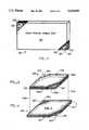
- FIG. 1shows a cross-sectional view of a conventional flat bi-cell battery.
- FIG. 2shows a perspective view of a conventional flat cell battery after the battery has been assembled and packaged.
- FIG. 3shows a perspective view of the newly designed flat cell battery in accordance with the present invention.
- FIG. 4shows a perspective view of a cathode laminate layer which is used in forming a flat cell battery in accordance with the present invention.
- FIG. 5shows a perspective view of an anode assembly layer which is used in forming a flat cell battery in accordance with the present invention.
- FIG. 6shows a top view of one embodiment of the present invention wherein anode and cathode terminals are formed using an electrically conductive plate 601.
- FIG. 6Ais a cross sectional view of the embodiment of FIG. 6 taken along the line 6A.
- FIG. 6Billustrates the technique of forming an anode terminal using the embodiment of FIG. 6A.
- FIG. 6Cillustrates the technique for forming a cathode terminal using the embodiment of FIG. 6A.
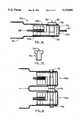
- FIG. 7shows a second embodiment of the present invention wherein anode and cathode terminals are formed using an electrically conductive plug 705.
- FIG. 7Ashows a cross sectional view of the embodiment of FIG. 7 taken along the line 7A.
- FIG. 7Bis a cross sectional view of the electrically conductive plug 701 of FIG. 7A.
- FIG. 8shows a cross sectional view of a multiple module battery wherein each of the individual battery modules is similar to the embodiment shown in FIG. 7A.
- FIG. 9illustrates a technique for forming cathode laminate layer 400 of FIG. 4.
- the terms “battery” or “flat cell battery” or “lithium battery”can include a single cell, or a plurality of cells connected in either series or parallel fashion to furnish electrical current.
- the term “cell” or “bi-cell”includes an anode layer, cathode layer, electrolyte layer, and a pair of electrically conductive terminals; or a plurality of these layers connected in bi-faced, bi-polar, or other cell configuration designs known in the art.
- terminalrefers to the portion of the flat cell battery which is used to electrically contact and to provide power to an external electronic device.
- tabor “foil” refers to an exposed portion of current collector material (i.e.
- cathode laminate materialrefers to the various layers of material (such as the cathode layer and the electrolyte layer) which are deposited onto the cathode current collector material to form a cathode laminate layer as illustrated in FIG. 4.
- anode materialrefers to the anode material (such as, for example, lithium) which is deposited onto the anode current collector material to form an anode assembly layer as illustrated in FIG. 5.
- FIG. 3a new flat cell battery design is shown wherein battery 300 comprises an anode terminal located at a first corner of the battery, and a cathode terminal located at a second corner of the battery.
- the terminals of the flat cell battery of the present inventionhave been designed so as to fit within the corners of the battery body 300.
- a preferred embodiment of the present inventionincludes a cathode terminal 301 located in a corner which is diametrically opposed to an anode terminal 303.
- the present inventionis not limited to the particular embodiment shown in FIG. 3, but may also include other embodiments where the anode and cathode terminals are located in respective corners which are not diametrically opposed to each other.
- FIG. 3depicts a flat cell battery which has the shape of a rectangular polyhedron.
- other battery shapesmay also be utilized, such as, for example, a cubicle battery, without departing from the scope of this invention.
- the flat cell battery design of the present inventionhas several advantages over conventional flat cell battery designs.
- the placement of the anode and cathode terminals in the corners of the battery bodyhelps to minimize the size of the battery package, and therefore reduces the space used within the package for housing the cathode and anode terminals. This, in turn, allows for a greater proportion of the battery package to be used for electro-chemical storage, thereby increasing the storage capacity and energy density of the battery.
- the anode terminalmay be located in a first corner at or near or adjacent to a first face of the battery while the cathode terminal is located in a second, diametrically opposed corner at or near or adjacent to a second face of the battery body.
- the anode terminalmay be located in a first corner on the top side of the battery while the cathode terminal is located in a diametrically opposed corner on the bottom side of the battery.
- the heat dissipation of the batteryis improved.
- This improvementoccurs as a result of the anode and cathode terminals of the present invention being spaced further apart than of those of conventional flat cell batteries.
- the regions of intensive current flow in the batteryare also caused to be spaced farther apart from each other.
- conventional flat cell batterieshave terminals which are close to each other and along one edge (as shown in FIG. 2), the regions of intensive current flow near these terminals overlap, in turn creating zones of high heat generation in these overlapping regions. The result is a non-uniform dispersion of heat within the battery of FIG. 2, and an increased heat gradient near the terminal edge.
- this heat gradientis reduced since there are little or no overlapping regions of intensive current flow, and therefore little or no zones of high heat generation within the battery.
- resistance R within the batterycan be reduced by locating the anode and cathode terminals in diametrically opposed corners. This "symmetric" design of the present invention also allows for better electro-chemical utilization of the cell.
- FIG. 3is an illustration of a flat multi-cell battery designed and built in accordance with the present invention.
- One corner of the cellcomprises a cathode terminal 301 while another corner of the cell comprises anode terminal 303.
- the remainder portion of the cell 350comprises the various anode, cathode, and electrolyte layers used for generating electro-chemical energy.
- FIGS. 4 and 5illustrate the technique for constructing a flat cell battery in accordance with the present invention.
- a cathode laminate layer 400is shown.
- the cathode laminate layercomprises a cathode layer of material and an electrolyte layer of material (collectively referred to as cathode laminate material and represented as layer 403) formed onto a layer of current collector material 401.
- Layer 401is made from an electrically conductive material, such as, for example aluminum.
- the composition of each of the layers within the cathode laminate 400is generally known to those skilled in the art and therefore will not be discussed further in this application.
- Each of the cathode laminate layers of the present inventionis constructed in a manner such that the finished product is similar to cathode laminate layer 400 of FIG. 4.
- Cathode laminate 400is shown to have a corner portion of cathode and electrolyte layer 403 removed, thereby exposing a corner portion 401a of the current collector material 401.
- both the cathode-electrolyte layer 403 and the current collector layer 401are removed (illustrated at 405) in order to allow the anode tab (not shown) to be exposed when the cathode and anode layers 400 and 500 are combined as described below.
- FIG. 5shows a perspective view of anode assembly layer 500 which comprises two layers of anode material 503a and 503b (such as, for example, lithium) sandwiching a layer of anode current collecting material 501, which typically is made out of a metallic foil such as, for example, copper.
- Anode assembly layer 500is formed in a manner such that a corner portion 505' of layer 500 is removed to allow exposure of cathode tab 401a (not shown) when layers 400 and 500 are combined as described below.
- the opposite corner portion 501ashows the absence of anode layers 503a and 503b, thereby exposing a corner portion of the copper foil 501a.
- layers 400 and 500After layers 400 and 500 have been formed, they are combined by stacking the layers together along dotted lines 531a and 531b. Additionally, a second cathode laminate layer similar to layer 400 is placed on top of anode assembly layer 500, with layer 403 of the second cathode laminate in contact with layer 503a of the anode assembly. The result is a flat bi-cell battery with anode assembly layer 500 sandwiched between two cathode laminate layers 400.
- cathode and anode layers 400 and 500are positioned such that each exposed corner portion of cathode current collector material 401a is located at a first corner while the exposed corner portion of anode copper foil 501a is located in a corner diagonally opposed from corners 401a. Additionally, during the battery assembly, a layer of mylar material (305 in FIG. 3) is deposited around the edges in between each of the cathode laminate and anode assembly layers 400 and 500.
- the mylar material(or mylar mask) is used because of the edge effects created by the anode assembly and cathode laminate. Its use prolongs the life cycle of the battery and prevents the anode tab from coming into contact with the cathode laminate, thereby reducing the possibility of inadvertent short-circuit between the anode assembly and cathode laminate layers. Since the greatest potential for short-circuiting occurs where the anode tab protrudes out from two layers of cathode laminate (near the anode terminal), the mylar material is deposited in this area so as to extend past the edge of the cathode laminate, as illustrated at 305 of FIG. 3. Additional examples of the above-described mylar layer are illustrated in FIGS. 6 and 7 as item 613.
- anode assembly layer 500is relatively straight forward.
- Anode layers 503a and 503bare formed directly onto the copper layer 501, forming an anode assembly similar to that shown in FIG. 5.
- anode layers 503a and 503bare formed onto copper layer 501 so as to expose a corner portion 501a of copper layer 501.
- This process of formationis possible because lithium anode layers 503a and 503b are viscous enough to retain their formed shapes before they are applied onto metallic layer 501.
- the other corner portion 505 of anode assembly 500may either be formed directly as shown in FIG.
- anode assembly layer 500may be formed by any of the processes described below for forming cathode laminate layer 400.
- cathode laminate layer 400is not quite as simple. This is because the cathode material and/or the electrolyte material within layer 403 does not have sufficient viscosity to hold its shape before it is formed onto current collector layer 401. To resolve this problem, there are at least three different techniques which may be used to form cathode laminate 400.
- a first techniqueutilizes a masking process, wherein a corner portion 401a of the current collector material 401 is masked off before the cathode-electrolyte layer 403 is formed onto the current collector layer 401. After the cathode laminate layer has been formed, the mask is removed, thereby exposing a corner portion of the cathode current collector material 401a.
- a second technique for forming cathode laminate 400is to first form a complete cathode-electrolyte layer 403 on current collector 401. As illustrated by the dotted lines in FIG. 4, the complete formed layer of cathode laminate would be rectangular in shape, and would include corner portion 401'. After the complete cathode laminate layer has been formed, corner portion 401' of the cathode-electrolyte layer 403 is etched away to thereby expose a corner portion of the current collector material 401a.
- the other corner portion 405 of the cathode laminate 400may be formed as shown in FIG. 4 by removing corner 405' after the complete cathode laminate layer 400 has been formed. This may be done either before of after corner portion 401a has been created using either of the methods described above. The end result is a cathode laminate layer 400 which resembles that of FIG. 4.
- a third technique for forming cathode laminate 400is illustrated in FIG. 9.
- a partial cathode laminate layer 900is formed by coating a portion of cathode current collector material 401 with cathode-electrolyte layer 403, leaving a portion of the cathode current collector material uncoated as shown at 401b.
- a portion of the partial cathode laminate layer 901is separated from the remainder of layer 900 along line 901' such that the separated portion 901 includes a corner portion of exposed current collector material 401a which is not covered by cathode-electrolyte layer 403.
- the technique used for separating portion 901 from layer 900can be, for example, cutting out portion 901 with a sharp edge, stamping out portion 901 with a stamping tool, or other techniques known to those skilled in the art.
- This third technique for forming cathode laminate 400is particularly useful for medium or low volume applications where the need to minimize waste is not as important a factor as it is in high volume applications.
- each of the exposed aluminum cathode collectors 401a and copper anode collectors 501ais then welded, bonded, and/or fastened to a respective copper plate, which acts as the respective cathode or anode terminal.
- the weldingmay be either by spot welding, ultrasonic welding, or resistance welding. The fastening technique is discussed in greater detail below.
- an electrically conductive adhesivemay be used.
- the groups of copper anode collectorsare fastened together in parallel as shown in FIG. 6B (discussed below).
- the groups of aluminum cathode collectorsare first welded together to reduce any resistance caused by oxide layers on the surface of each aluminum tab.
- the welded groupsare then fastened together in parallel as shown in FIG. 6C (discussed below).
- FIG. 3shows a plurality of cathode terminals 309 and a plurality of anode terminals 311, each being respectively connected together by fasteners 307.
- the fastenersextend perpendicularly through the plane of each corner terminal 301, 303, thereby physically and electrically securing together each of the respective anode and cathode terminals.
- the fastenersmay be copper, bronze or brass bolts, or any other bolt made from a material chosen to avoid dissimilar metal junctions between the terminal and the fastener.
- FIGS. 6 and 7illustrate two different embodiments of the corner terminals of the present invention.
- Each of the embodiments shown in FIGS. 6 and 7may be utilized for constructing either the anode or cathode terminal. Therefore, for purposes of simplification, the following discussion of FIGS. 6 and 7 will be limited to a discussion of how to construct a corner cathode terminal, with the understanding that the discussion is equally applicable constructing an anode corner terminal.
- FIGS. 6 through 7Aillustrate different embodiments for constructing a corner terminal for flat multi-cell batteries, it is to be understood that the embodiments shown are not limited exclusively to multi-cell batteries, but may also be used in the construction of cornered terminals for single-cell batteries, as would readily be apparent to those skilled in the art.
- FIG. 6a first embodiment of a corner terminal of the present invention is shown wherein multiple cathode current collector foils 609 are electrically connected to metallic plate 601, with the metallic plate 601 functioning as the cathode terminal of the battery 600.
- the embodiment of FIG. 6may more readily be understood by referring to FIG. 6A.
- FIG. 6Ais a cross-sectional view of the embodiment of FIG. 6 taken along the line 6A.
- a plurality of exposed current collector foils 609extend out from a plurality of cathode laminate layers (not shown). Each of the foil layers in the plurality of foil layers 609 corresponds to an exposed corner portion of current collector material 401a (FIG. 4).
- a metallic plate 601, which, for example, is made of copper,is interposed between the plurality of cathode foils 609. Electrical contact between the foils 609 and the copper plate 601 is insured by clamping the foils 609 and the metallic plate 601 between two additional metallic plates 607a and 607b which, for example, may also be made of copper. The plates 607a and 607b are secured together by fasteners 615 (shown in FIG. 6).
- the fastenersmay either be threaded bolts or rivets or other fastening devices which can be used to securely clamp together upper and lower clamp plates 607a and 607b.
- the fasteners usedare rivets
- through-holesare made in each of the plates into which a respective rivet is inserted.
- the bottom portion of each rivet(opposite its head) is then hammered into a flash or mushroom shape, thereby securing the plates together.
- the fasteners usedare bolts
- the bottom platewill include at least one threaded aperture into which a respective bolt is inserted and screwed in, thereby securing the plates together.
- FIG. 6AAdditionally shown in FIG. 6A is a portion of a vacuum sealed bag 611 which encases the entire battery except for the anode and cathode terminals, thereby providing environmental protection to the battery body.
- the bagis non-conductive, further providing electrostatic discharge protection to the battery.
- Conventional batterieshave been known to use vacuum sealed bags; however, the bag illustrated in the present invention has been re-designed to allow exposure of the corner terminals 601 to the outside environment.
- the bag 611is heat sealed along portions of the top and bottom surfaces of plate 601 at 605.
- the vacuum bagis made out of a nylon plus aluminum plus ethylene acrylic acetate (EAA) material.
- EAAis a plastic resin.
- Other types of plastic resin materialsmay be used, for example, Surlyn (a registered trademark of E. I. du Pont Nemours and Company), so long as they have similar metallic adhesive properties.
- the plastic resin materialpreferably has a sufficient level of acidity in it so that when it is applied to the metal surface, the acid is able to clean the metal surface in order for the plastic resin material to form a secure bond to the metal surface.
- FIGS. 6B and 6Cillustrate how anode and cathode terminals are each constructed using the technique of FIG. 6A.
- FIG. 6Billustrates the technique of forming an anode terminal according to the embodiment of FIG. 6A.
- a bi-cell 603is encased in a stacking frame with top and bottom portions 620a and 620b.
- the individual anode foil layers 501a(FIG. 5) are positioned into place by a plurality of intermediate frames 622.
- the vacuum bagis represented as item 611.
- Top and bottom clamp platesare depicted as items 607a and 607b, held together by a fastener 615, which, for example, is a brass bolt.
- additional copper spacers 632are added to expand the thickness of the area to be clamped to match that of the cathode terminal.
- the spacers 632are needed because there are typically fewer anode assembly layers in a multi-cell battery than there are cathode laminate layers.
- FIG. 6Cdepicts many of the features of FIG. 6B, with the inclusion of ultrasonic shim welds 634 placed on the top and bottom of each group of aluminum cathode foils 401a (FIG. 4).
- the material used for the shim weldsis preferably similar to the material used for the terminal so as to avoid dissimilar metal junctions. Such a material is, for example, copper.
- the ultrasonic shim weldsaid in the process of welding the aluminum cathode foils to the copper plate 601. Additionally the shim welds aid in the electrical connection between each of the welded groups by reducing the resistance caused by oxide layers (which occur on the surface of each aluminum layer).
- Bi-cell tabs 609are shown being clamped by clamp plates 607a and 607b (not shown), which insures proper electrical connection between the bi-cell tabs 609 and the corner terminal plate 601.
- the clamp plates 607a and bare held together by fastener 615.
- the mylar mask(discussed previously) is shown to be deposited along the edges of the battery cell layers at 613.
- the vacuum bagis represented as item 611.
- the bagis sealed to itself along edges 617, and is heat sealed to the copper terminal 601 at area 605.
- the thickness of terminal 601can be for example 0.012-0.015 inches.
- FIG. 7shows an alternate embodiment of the corner terminal of the present invention, a discussion of which may be facilitated by reference to FIG. 7A.
- FIG. 7Ashows a cross-sectional view of the embodiment of FIG. 7 taken along the line 7A.
- Bi-cell tabs 609are clamped between plates 607a and 607b.
- Plate 607bincludes an arm 607c which extends into the corner of the battery, adjacent to bi-cell tabs 609.
- the arm 607cincludes an aperture 702 into which a metallic plug 701 is inserted.
- the plug 701is illustrated in FIG. 7B.
- the plugmakes electrical contact with arm 607c, which, in turn, makes electrical contact with bi-cell foils 609.
- the head of plug 701functions as the electrical terminal of the battery.
- Vacuum sealed bag 611is again used, however, this time, as shown, the bag encases the entire battery and is heat sealed to itself at ends 617.
- the bagis further adhered to the surface of plate 607b and arm 607c at areas 703.
- the adhesive shown in areas 703is an ionomer painted onto the surface of the copper plate
- a small apertureis created in the bag where plug 701 is inserted into arm 607c. Both the arm 607c and plug 701 include an aperture 704 by which to secure together multiple cells or modules (discussed below). This is illustrated in FIG. 8.
- two battery cells 700a and 700bare shown being electrically and physically connected together by fastening bolt 751 and nut 755.
- One of the battery cells 700ais oriented in the direction similar to that shown in FIG. 7A.
- the other battery cell 700bis oriented upside down (compared to the orientation shown in FIG. 7A) and positioned such that the anode terminal of cell 700a is connectable with the cathode terminal of cell 700b.
- An electrically conductive bolt 751is inserted into the aperture shaft 704 of the respective battery cells, and is secured on the other end by nut 755. In this manner, a number of battery cells or modules may be electrically and physically secured together in series, thereby forming a composite battery with increased voltage and energy.
- each of the anode terminalsmay be attached in series to a respective cathode terminal via fasteners 603 (FIG. 6) which extend perpendicularly through the plane of each corner terminal 601, thereby physically and electrically securing each of the respective anode and cathode terminals together.
- the fastenersmay be copper, bronze or brass bolts, or any other bolt made from a material chosen to avoid dissimilar metal junctions between the terminal and the fastener.
- Bi-cell tabs 609are clamped together by plate 607a and 607b (not shown). The plates are held together by fasteners 615.
- Vacuum sealed bag 611is shown to encase the entire battery 700, where it is heat sealed to itself along edges 617.
- bag 611is adhered to the surface of plate 607b and arm 607c by an ionomer coating 703.
- Plug 701is shown to extend through the bag 611 and ionomer coating into arm 607c (not shown).
- An aperture 704extends longitudinally through the plug 701 and arm 607c.
- the mylar mask 613is shown to be deposited along the edges between each anode assembly and cathode laminate layers, as discussed previously.
Landscapes
- Chemical & Material Sciences (AREA)
- Chemical Kinetics & Catalysis (AREA)
- Electrochemistry (AREA)
- General Chemical & Material Sciences (AREA)
- Engineering & Computer Science (AREA)
- Manufacturing & Machinery (AREA)
- Connection Of Batteries Or Terminals (AREA)
Abstract
Description
Claims (10)
Priority Applications (3)
| Application Number | Priority Date | Filing Date | Title |
|---|---|---|---|
| US08/163,204US5419982A (en) | 1993-12-06 | 1993-12-06 | Corner tab termination for flat-cell batteries |
| AU14316/95AAU1431695A (en) | 1993-12-06 | 1994-12-05 | Corner tab termination for flat-cell batteries |
| PCT/US1994/014047WO1995016283A1 (en) | 1993-12-06 | 1994-12-05 | Corner tab termination for flat-cell batteries |
Applications Claiming Priority (1)
| Application Number | Priority Date | Filing Date | Title |
|---|---|---|---|
| US08/163,204US5419982A (en) | 1993-12-06 | 1993-12-06 | Corner tab termination for flat-cell batteries |
Publications (1)
| Publication Number | Publication Date |
|---|---|
| US5419982Atrue US5419982A (en) | 1995-05-30 |
Family
ID=22588919
Family Applications (1)
| Application Number | Title | Priority Date | Filing Date |
|---|---|---|---|
| US08/163,204Expired - Fee RelatedUS5419982A (en) | 1993-12-06 | 1993-12-06 | Corner tab termination for flat-cell batteries |
Country Status (3)
| Country | Link |
|---|---|
| US (1) | US5419982A (en) |
| AU (1) | AU1431695A (en) |
| WO (1) | WO1995016283A1 (en) |
Cited By (56)
| Publication number | Priority date | Publication date | Assignee | Title |
|---|---|---|---|---|
| WO1997008769A1 (en)* | 1995-08-25 | 1997-03-06 | Valence Technology, Inc. | Current collector having electrode material on two sides for use in a laminate battery and method of making a battery |
| EP0814529A1 (en)* | 1996-06-19 | 1997-12-29 | Koninklijke Philips Electronics N.V. | Thin card containing flat accumulator and connecting devices |
| US5788178A (en)* | 1995-06-08 | 1998-08-04 | Barrett, Jr.; Rolin F. | Guided bullet |
| EP0863564A1 (en)* | 1997-02-18 | 1998-09-09 | Koninklijke Philips Electronics N.V. | Thin type accumulator device comprising an electrochemical cell and electrical contact means |
| US6051338A (en)* | 1996-08-22 | 2000-04-18 | Dai Nippon Printing Co., Ltd. | Electrode plate for secondary battery with nonaqueous electrolyte |
| US6152971A (en)* | 1996-11-06 | 2000-11-28 | Dai Nippon Printing Co., Ltd. | Electrode plate for secondary battery with nonaqueous electrolyte and process for producing same |
| US6162264A (en)* | 1996-06-17 | 2000-12-19 | Dai Nippon Printing Co., Ltd. | Process for producing porous coating layer electrode plate for secondary battery with nonaqueous electrolyte process for producing same and sheet for peeling active material layer |
| US6267790B1 (en)* | 1998-03-18 | 2001-07-31 | Ntk Powerdex, Inc. | Treatment of conductive feedthroughs for battery packaging |
| EP1134832A2 (en) | 2000-03-17 | 2001-09-19 | Sony Corporation | Method of manufacturing a battery |
| US6653023B1 (en)* | 1999-03-25 | 2003-11-25 | Sanyo Electric Co., Ltd. | Rectangular battery |
| US20040175609A1 (en)* | 2003-03-03 | 2004-09-09 | Nec Lamilion Energy, Ltd. | Film covered battery and stacked battery assembly |
| US20040224227A1 (en)* | 2003-05-05 | 2004-11-11 | Kazunori Ozawa | Lead outlet structure of secondary battery in sheet type |
| US20050174092A1 (en)* | 2003-10-28 | 2005-08-11 | Johnson Controls Technology Company | Battery system |
| EP1067611A4 (en)* | 1998-03-26 | 2005-11-16 | Tdk Corp | Electrode for cell, method of manufacturing the same and cell |
| US20060083980A1 (en)* | 2004-10-08 | 2006-04-20 | Choo Hyun S | Secondary battery module |
| US20080020272A1 (en)* | 2006-07-24 | 2008-01-24 | Paul Leslie Kemper | Device and method for producing layered battery cells |
| US20090095409A1 (en)* | 2007-10-01 | 2009-04-16 | Angstrom Power Incorporated | Methods of manufacturing electrochemical cells |
| US20090169991A1 (en)* | 2007-12-27 | 2009-07-02 | Industrial Technology Research Institute | Flexible envelope type battery and electrically conductible sealing structure thereof and assembling method thereof |
| US20090197180A1 (en)* | 2008-01-31 | 2009-08-06 | Viavattine Joseph J | Spacers between tabs of electrode plates in an electrochemical cell for an implantable medical device |
| US7718319B2 (en) | 2006-09-25 | 2010-05-18 | Board Of Regents, The University Of Texas System | Cation-substituted spinel oxide and oxyfluoride cathodes for lithium ion batteries |
| US7823510B1 (en) | 2008-05-14 | 2010-11-02 | Pratt & Whitney Rocketdyne, Inc. | Extended range projectile |
| US20100307367A1 (en)* | 2008-05-14 | 2010-12-09 | Minick Alan B | Guided projectile |
| US20110003187A1 (en)* | 2009-07-03 | 2011-01-06 | Visteon Global Technologies, Inc. | Battery Unit For Hybrid Or Electric Vehicles |
| US7959769B2 (en) | 2004-12-08 | 2011-06-14 | Infinite Power Solutions, Inc. | Deposition of LiCoO2 |
| US7993773B2 (en) | 2002-08-09 | 2011-08-09 | Infinite Power Solutions, Inc. | Electrochemical apparatus with barrier layer protected substrate |
| US8021778B2 (en) | 2002-08-09 | 2011-09-20 | Infinite Power Solutions, Inc. | Electrochemical apparatus with barrier layer protected substrate |
| US8062708B2 (en) | 2006-09-29 | 2011-11-22 | Infinite Power Solutions, Inc. | Masking of and material constraint for depositing battery layers on flexible substrates |
| USRE43449E1 (en)* | 2001-09-04 | 2012-06-05 | Nec Corporation | Film packaged battery having a cupped portion |
| US8197781B2 (en) | 2006-11-07 | 2012-06-12 | Infinite Power Solutions, Inc. | Sputtering target of Li3PO4 and method for producing same |
| US8236443B2 (en) | 2002-08-09 | 2012-08-07 | Infinite Power Solutions, Inc. | Metal film encapsulation |
| US8260203B2 (en) | 2008-09-12 | 2012-09-04 | Infinite Power Solutions, Inc. | Energy device with integral conductive surface for data communication via electromagnetic energy and method thereof |
| US8268488B2 (en) | 2007-12-21 | 2012-09-18 | Infinite Power Solutions, Inc. | Thin film electrolyte for thin film batteries |
| US8350519B2 (en) | 2008-04-02 | 2013-01-08 | Infinite Power Solutions, Inc | Passive over/under voltage control and protection for energy storage devices associated with energy harvesting |
| US8394522B2 (en) | 2002-08-09 | 2013-03-12 | Infinite Power Solutions, Inc. | Robust metal film encapsulation |
| US8404376B2 (en) | 2002-08-09 | 2013-03-26 | Infinite Power Solutions, Inc. | Metal film encapsulation |
| US8431264B2 (en) | 2002-08-09 | 2013-04-30 | Infinite Power Solutions, Inc. | Hybrid thin-film battery |
| US8445130B2 (en) | 2002-08-09 | 2013-05-21 | Infinite Power Solutions, Inc. | Hybrid thin-film battery |
| US8508193B2 (en) | 2008-10-08 | 2013-08-13 | Infinite Power Solutions, Inc. | Environmentally-powered wireless sensor module |
| US8518581B2 (en) | 2008-01-11 | 2013-08-27 | Inifinite Power Solutions, Inc. | Thin film encapsulation for thin film batteries and other devices |
| US8599572B2 (en) | 2009-09-01 | 2013-12-03 | Infinite Power Solutions, Inc. | Printed circuit board with integrated thin film battery |
| US8614017B2 (en) | 2010-10-27 | 2013-12-24 | Medtronic, Inc. | Electrochemical cell with electrode elements that include alignment aperatures |
| US8636876B2 (en) | 2004-12-08 | 2014-01-28 | R. Ernest Demaray | Deposition of LiCoO2 |
| US8728285B2 (en) | 2003-05-23 | 2014-05-20 | Demaray, Llc | Transparent conductive oxides |
| US8841020B2 (en) | 2010-10-27 | 2014-09-23 | Medtronic, Inc. | Electrochemical cell with a direct connection between a feedthrough pin and an electrode stack |
| US8906523B2 (en) | 2008-08-11 | 2014-12-09 | Infinite Power Solutions, Inc. | Energy device with integral collector surface for electromagnetic energy harvesting and method thereof |
| US9142840B2 (en) | 2011-10-21 | 2015-09-22 | Blackberry Limited | Method of reducing tabbing volume required for external connections |
| US20150280270A1 (en)* | 2014-03-31 | 2015-10-01 | Dell Products, L.P. | Preventing internal short circuit in a lithium-ion battery cell |
| US9334557B2 (en) | 2007-12-21 | 2016-05-10 | Sapurast Research Llc | Method for sputter targets for electrolyte films |
| US9634296B2 (en) | 2002-08-09 | 2017-04-25 | Sapurast Research Llc | Thin film battery on an integrated circuit or circuit board and method thereof |
| US10147926B1 (en)* | 2014-04-15 | 2018-12-04 | Amazon Technologies, Inc. | Battery package including electrode having recessed region of electrode material layer exposing a portion of a conductive layer and method of making the same |
| US10446828B2 (en) | 2011-10-21 | 2019-10-15 | Blackberry Limited | Recessed tab for higher energy density and thinner batteries |
| US10680277B2 (en) | 2010-06-07 | 2020-06-09 | Sapurast Research Llc | Rechargeable, high-density electrochemical device |
| US11065460B2 (en) | 2019-05-30 | 2021-07-20 | Medtronic, Inc. | Battery assembly for medical device |
| WO2021233898A1 (en)* | 2020-05-19 | 2021-11-25 | Saft | Electrochemical element and corresponding battery |
| US11413466B2 (en) | 2019-04-18 | 2022-08-16 | Medtronic, Inc. | Battery assembly for medical device |
| WO2022243243A1 (en)* | 2021-05-18 | 2022-11-24 | Saft | Electrochemical element for a battery, and corresponding battery |
Citations (8)
| Publication number | Priority date | Publication date | Assignee | Title |
|---|---|---|---|---|
| US3734780A (en)* | 1971-06-25 | 1973-05-22 | Esb Inc | Flat cell battery with both terminals on one face |
| US4751150A (en)* | 1986-04-15 | 1988-06-14 | Sharp Kabushiki Kaisha | Paper battery |
| US4929518A (en)* | 1986-03-19 | 1990-05-29 | Matsushita Electric Industrial Co., Ltd. | Sealed lead-acid storage battery |
| US4997732A (en)* | 1989-03-30 | 1991-03-05 | Mhb Joint Venture | Battery in a vacuum sealed enveloping material and a process for making the same |
| US5017441A (en)* | 1989-08-08 | 1991-05-21 | Elgin Molded Plastics, Inc. | Battery pack |
| US5102753A (en)* | 1990-11-26 | 1992-04-07 | Gould Inc. | Constant current source power supply |
| US5230967A (en)* | 1990-06-20 | 1993-07-27 | Paul Radmall | Battery comprising interconnecting means of electrochemical cell units |
| US5362579A (en)* | 1992-11-27 | 1994-11-08 | Gould Electronics Inc. | Solder sealed solid electrolyte cell housed within a ceramic frame and the method for producing it |
Family Cites Families (6)
| Publication number | Priority date | Publication date | Assignee | Title |
|---|---|---|---|---|
| FR1024203A (en)* | 1950-09-01 | 1953-03-30 | Pilex Agon Soc | Process for the parallel combination of cells in cells with so-called <flat> cells and, in particular, in those with bipolar plates |
| DE1671486A1 (en)* | 1965-10-24 | 1971-11-18 | Texas Instruments Inc | Plates for electrochemical devices, plate assembly and device using the plate assemblies |
| DE1596301B1 (en)* | 1966-09-02 | 1970-06-18 | Varta Ag | Electrode set for galvanic elements |
| JPS61225770A (en)* | 1985-03-29 | 1986-10-07 | Toshiba Battery Co Ltd | flat battery |
| JP2734519B2 (en)* | 1988-03-24 | 1998-03-30 | 松下電器産業株式会社 | Flat battery pack |
| DE69218587T2 (en)* | 1991-12-06 | 1997-08-14 | Yuasa Battery Co Ltd | THIN BATTERY AND MONOLITICAL THIN BATTERY |
- 1993
- 1993-12-06USUS08/163,204patent/US5419982A/ennot_activeExpired - Fee Related
- 1994
- 1994-12-05AUAU14316/95Apatent/AU1431695A/ennot_activeAbandoned
- 1994-12-05WOPCT/US1994/014047patent/WO1995016283A1/enactiveApplication Filing
Patent Citations (8)
| Publication number | Priority date | Publication date | Assignee | Title |
|---|---|---|---|---|
| US3734780A (en)* | 1971-06-25 | 1973-05-22 | Esb Inc | Flat cell battery with both terminals on one face |
| US4929518A (en)* | 1986-03-19 | 1990-05-29 | Matsushita Electric Industrial Co., Ltd. | Sealed lead-acid storage battery |
| US4751150A (en)* | 1986-04-15 | 1988-06-14 | Sharp Kabushiki Kaisha | Paper battery |
| US4997732A (en)* | 1989-03-30 | 1991-03-05 | Mhb Joint Venture | Battery in a vacuum sealed enveloping material and a process for making the same |
| US5017441A (en)* | 1989-08-08 | 1991-05-21 | Elgin Molded Plastics, Inc. | Battery pack |
| US5230967A (en)* | 1990-06-20 | 1993-07-27 | Paul Radmall | Battery comprising interconnecting means of electrochemical cell units |
| US5102753A (en)* | 1990-11-26 | 1992-04-07 | Gould Inc. | Constant current source power supply |
| US5362579A (en)* | 1992-11-27 | 1994-11-08 | Gould Electronics Inc. | Solder sealed solid electrolyte cell housed within a ceramic frame and the method for producing it |
Cited By (82)
| Publication number | Priority date | Publication date | Assignee | Title |
|---|---|---|---|---|
| US5788178A (en)* | 1995-06-08 | 1998-08-04 | Barrett, Jr.; Rolin F. | Guided bullet |
| WO1997008769A1 (en)* | 1995-08-25 | 1997-03-06 | Valence Technology, Inc. | Current collector having electrode material on two sides for use in a laminate battery and method of making a battery |
| US6162264A (en)* | 1996-06-17 | 2000-12-19 | Dai Nippon Printing Co., Ltd. | Process for producing porous coating layer electrode plate for secondary battery with nonaqueous electrolyte process for producing same and sheet for peeling active material layer |
| EP0814529A1 (en)* | 1996-06-19 | 1997-12-29 | Koninklijke Philips Electronics N.V. | Thin card containing flat accumulator and connecting devices |
| US6051338A (en)* | 1996-08-22 | 2000-04-18 | Dai Nippon Printing Co., Ltd. | Electrode plate for secondary battery with nonaqueous electrolyte |
| US6152971A (en)* | 1996-11-06 | 2000-11-28 | Dai Nippon Printing Co., Ltd. | Electrode plate for secondary battery with nonaqueous electrolyte and process for producing same |
| US6120935A (en)* | 1997-02-18 | 2000-09-19 | U.S. Philips Corporation | Flat accumulator device having an electrochemical cell and electrical contacts |
| EP0863564A1 (en)* | 1997-02-18 | 1998-09-09 | Koninklijke Philips Electronics N.V. | Thin type accumulator device comprising an electrochemical cell and electrical contact means |
| JPH10255734A (en)* | 1997-02-18 | 1998-09-25 | Philips Electron Nv | Flat storage battery comprising electrochemical battery and electric contact means |
| US6267790B1 (en)* | 1998-03-18 | 2001-07-31 | Ntk Powerdex, Inc. | Treatment of conductive feedthroughs for battery packaging |
| EP1067611A4 (en)* | 1998-03-26 | 2005-11-16 | Tdk Corp | Electrode for cell, method of manufacturing the same and cell |
| US6653023B1 (en)* | 1999-03-25 | 2003-11-25 | Sanyo Electric Co., Ltd. | Rectangular battery |
| EP1134832A2 (en) | 2000-03-17 | 2001-09-19 | Sony Corporation | Method of manufacturing a battery |
| US20050155215A1 (en)* | 2000-03-17 | 2005-07-21 | Takanobu Yoshino | Method of manufacturing a battery |
| EP1134832A3 (en)* | 2000-03-17 | 2006-08-16 | Sony Corporation | Method of manufacturing a battery |
| USRE43449E1 (en)* | 2001-09-04 | 2012-06-05 | Nec Corporation | Film packaged battery having a cupped portion |
| US8431264B2 (en) | 2002-08-09 | 2013-04-30 | Infinite Power Solutions, Inc. | Hybrid thin-film battery |
| US8236443B2 (en) | 2002-08-09 | 2012-08-07 | Infinite Power Solutions, Inc. | Metal film encapsulation |
| US8021778B2 (en) | 2002-08-09 | 2011-09-20 | Infinite Power Solutions, Inc. | Electrochemical apparatus with barrier layer protected substrate |
| US7993773B2 (en) | 2002-08-09 | 2011-08-09 | Infinite Power Solutions, Inc. | Electrochemical apparatus with barrier layer protected substrate |
| US8404376B2 (en) | 2002-08-09 | 2013-03-26 | Infinite Power Solutions, Inc. | Metal film encapsulation |
| US8445130B2 (en) | 2002-08-09 | 2013-05-21 | Infinite Power Solutions, Inc. | Hybrid thin-film battery |
| US8535396B2 (en) | 2002-08-09 | 2013-09-17 | Infinite Power Solutions, Inc. | Electrochemical apparatus with barrier layer protected substrate |
| US9793523B2 (en) | 2002-08-09 | 2017-10-17 | Sapurast Research Llc | Electrochemical apparatus with barrier layer protected substrate |
| US9634296B2 (en) | 2002-08-09 | 2017-04-25 | Sapurast Research Llc | Thin film battery on an integrated circuit or circuit board and method thereof |
| US8394522B2 (en) | 2002-08-09 | 2013-03-12 | Infinite Power Solutions, Inc. | Robust metal film encapsulation |
| US7468220B2 (en)* | 2003-03-03 | 2008-12-23 | Nec Corporation | Film covered battery and stacked battery assembly |
| US7604894B2 (en) | 2003-03-03 | 2009-10-20 | Nec Corporation | Film covered battery and stacked battery assembly |
| US20080090143A1 (en)* | 2003-03-03 | 2008-04-17 | Nec Lamilion Energy, Ltd. | Film covered battery and stacked battery assembly |
| US20040175609A1 (en)* | 2003-03-03 | 2004-09-09 | Nec Lamilion Energy, Ltd. | Film covered battery and stacked battery assembly |
| US20040224227A1 (en)* | 2003-05-05 | 2004-11-11 | Kazunori Ozawa | Lead outlet structure of secondary battery in sheet type |
| US7014950B2 (en)* | 2003-05-05 | 2006-03-21 | Enax, Inc. | Lead outlet structure of secondary battery in sheet type |
| US8728285B2 (en) | 2003-05-23 | 2014-05-20 | Demaray, Llc | Transparent conductive oxides |
| US8632898B2 (en) | 2003-10-28 | 2014-01-21 | Johnson Controls Technology Company | Battery system including batteries that have a plurality of positive terminals and a plurality of negative terminals |
| US20050174092A1 (en)* | 2003-10-28 | 2005-08-11 | Johnson Controls Technology Company | Battery system |
| US7758999B2 (en)* | 2004-10-08 | 2010-07-20 | Lg Chem, Ltd. | Secondary battery module |
| US20060083980A1 (en)* | 2004-10-08 | 2006-04-20 | Choo Hyun S | Secondary battery module |
| US8636876B2 (en) | 2004-12-08 | 2014-01-28 | R. Ernest Demaray | Deposition of LiCoO2 |
| US7959769B2 (en) | 2004-12-08 | 2011-06-14 | Infinite Power Solutions, Inc. | Deposition of LiCoO2 |
| US20080020272A1 (en)* | 2006-07-24 | 2008-01-24 | Paul Leslie Kemper | Device and method for producing layered battery cells |
| US8722246B2 (en) | 2006-09-25 | 2014-05-13 | Board Of Regents Of The University Of Texas System | Cation-substituted spinel oxide and oxyfluoride cathodes for lithium ion batteries |
| US7718319B2 (en) | 2006-09-25 | 2010-05-18 | Board Of Regents, The University Of Texas System | Cation-substituted spinel oxide and oxyfluoride cathodes for lithium ion batteries |
| US8062708B2 (en) | 2006-09-29 | 2011-11-22 | Infinite Power Solutions, Inc. | Masking of and material constraint for depositing battery layers on flexible substrates |
| US8197781B2 (en) | 2006-11-07 | 2012-06-12 | Infinite Power Solutions, Inc. | Sputtering target of Li3PO4 and method for producing same |
| US9056449B2 (en)* | 2007-10-01 | 2015-06-16 | Intelligent Energy Limited | Methods of manufacturing electrochemical cells |
| US20090095409A1 (en)* | 2007-10-01 | 2009-04-16 | Angstrom Power Incorporated | Methods of manufacturing electrochemical cells |
| US8268488B2 (en) | 2007-12-21 | 2012-09-18 | Infinite Power Solutions, Inc. | Thin film electrolyte for thin film batteries |
| US9334557B2 (en) | 2007-12-21 | 2016-05-10 | Sapurast Research Llc | Method for sputter targets for electrolyte films |
| US8353971B2 (en)* | 2007-12-27 | 2013-01-15 | Industrial Technology Research Institute | Flexible envelope type battery and electrically conductible sealing structure thereof and assembling method thereof |
| US8691432B2 (en) | 2007-12-27 | 2014-04-08 | Industrial Technology Research Institute | Flexible envelope type battery and electrically conductible sealing structure thereof and assembling method thereof |
| US20090169991A1 (en)* | 2007-12-27 | 2009-07-02 | Industrial Technology Research Institute | Flexible envelope type battery and electrically conductible sealing structure thereof and assembling method thereof |
| US8518581B2 (en) | 2008-01-11 | 2013-08-27 | Inifinite Power Solutions, Inc. | Thin film encapsulation for thin film batteries and other devices |
| US9786873B2 (en) | 2008-01-11 | 2017-10-10 | Sapurast Research Llc | Thin film encapsulation for thin film batteries and other devices |
| US20090197180A1 (en)* | 2008-01-31 | 2009-08-06 | Viavattine Joseph J | Spacers between tabs of electrode plates in an electrochemical cell for an implantable medical device |
| US8350519B2 (en) | 2008-04-02 | 2013-01-08 | Infinite Power Solutions, Inc | Passive over/under voltage control and protection for energy storage devices associated with energy harvesting |
| US7891298B2 (en) | 2008-05-14 | 2011-02-22 | Pratt & Whitney Rocketdyne, Inc. | Guided projectile |
| US20100307367A1 (en)* | 2008-05-14 | 2010-12-09 | Minick Alan B | Guided projectile |
| US7823510B1 (en) | 2008-05-14 | 2010-11-02 | Pratt & Whitney Rocketdyne, Inc. | Extended range projectile |
| US8906523B2 (en) | 2008-08-11 | 2014-12-09 | Infinite Power Solutions, Inc. | Energy device with integral collector surface for electromagnetic energy harvesting and method thereof |
| US8260203B2 (en) | 2008-09-12 | 2012-09-04 | Infinite Power Solutions, Inc. | Energy device with integral conductive surface for data communication via electromagnetic energy and method thereof |
| US8508193B2 (en) | 2008-10-08 | 2013-08-13 | Infinite Power Solutions, Inc. | Environmentally-powered wireless sensor module |
| CN101944643B (en)* | 2009-07-03 | 2015-02-18 | 汉拿伟世通空调有限公司 | Battery unit for hybrid or electric vehicles |
| US20110003187A1 (en)* | 2009-07-03 | 2011-01-06 | Visteon Global Technologies, Inc. | Battery Unit For Hybrid Or Electric Vehicles |
| CN101944643A (en)* | 2009-07-03 | 2011-01-12 | 威斯通全球技术公司 | The battery component that is used for motor vehicle driven by mixed power or motor vehicle |
| US8524387B2 (en)* | 2009-07-03 | 2013-09-03 | Visteon Global Technologies, Inc. | Battery unit for hybrid or electric vehicles |
| US9532453B2 (en) | 2009-09-01 | 2016-12-27 | Sapurast Research Llc | Printed circuit board with integrated thin film battery |
| US8599572B2 (en) | 2009-09-01 | 2013-12-03 | Infinite Power Solutions, Inc. | Printed circuit board with integrated thin film battery |
| US10680277B2 (en) | 2010-06-07 | 2020-06-09 | Sapurast Research Llc | Rechargeable, high-density electrochemical device |
| US8614017B2 (en) | 2010-10-27 | 2013-12-24 | Medtronic, Inc. | Electrochemical cell with electrode elements that include alignment aperatures |
| US8841020B2 (en) | 2010-10-27 | 2014-09-23 | Medtronic, Inc. | Electrochemical cell with a direct connection between a feedthrough pin and an electrode stack |
| US9142840B2 (en) | 2011-10-21 | 2015-09-22 | Blackberry Limited | Method of reducing tabbing volume required for external connections |
| US10446828B2 (en) | 2011-10-21 | 2019-10-15 | Blackberry Limited | Recessed tab for higher energy density and thinner batteries |
| US20150280270A1 (en)* | 2014-03-31 | 2015-10-01 | Dell Products, L.P. | Preventing internal short circuit in a lithium-ion battery cell |
| US9379410B2 (en)* | 2014-03-31 | 2016-06-28 | Dell Products, L.P. | Preventing internal short circuit in a lithium-ion battery cell |
| US10147926B1 (en)* | 2014-04-15 | 2018-12-04 | Amazon Technologies, Inc. | Battery package including electrode having recessed region of electrode material layer exposing a portion of a conductive layer and method of making the same |
| US11413466B2 (en) | 2019-04-18 | 2022-08-16 | Medtronic, Inc. | Battery assembly for medical device |
| US12311187B2 (en) | 2019-04-18 | 2025-05-27 | Medtronic, Inc. | Battery assembly for medical device |
| US11065460B2 (en) | 2019-05-30 | 2021-07-20 | Medtronic, Inc. | Battery assembly for medical device |
| WO2021233898A1 (en)* | 2020-05-19 | 2021-11-25 | Saft | Electrochemical element and corresponding battery |
| FR3110771A1 (en)* | 2020-05-19 | 2021-11-26 | Saft | Electrochemical element and corresponding battery |
| WO2022243243A1 (en)* | 2021-05-18 | 2022-11-24 | Saft | Electrochemical element for a battery, and corresponding battery |
| FR3123159A1 (en)* | 2021-05-18 | 2022-11-25 | Saft | Electrochemical element for battery, and corresponding battery |
Also Published As
| Publication number | Publication date |
|---|---|
| WO1995016283A1 (en) | 1995-06-15 |
| AU1431695A (en) | 1995-06-27 |
Similar Documents
| Publication | Publication Date | Title |
|---|---|---|
| US5419982A (en) | Corner tab termination for flat-cell batteries | |
| EP3540817B1 (en) | Battery pack | |
| KR102059077B1 (en) | Battery module, battery pack comprising the battery module and vehicle comprising the battery pack | |
| EP4235917B1 (en) | Pouch forming apparatus and method | |
| EP3676888B1 (en) | Lead tab for a battery terminal | |
| US11984612B2 (en) | Battery module comprising module housing | |
| KR20090075482A (en) | Protective circuit board, battery pack and manufacturing method thereof | |
| US8697265B2 (en) | Protection circuit module for secondary battery and battery pack having the same | |
| JPH11506264A (en) | Electrical connection to polymer stack battery structure | |
| JP3998736B2 (en) | Flat battery module | |
| EP4224621B1 (en) | Secondary battery and device including same | |
| CN112864534B (en) | Battery cell assembly, battery cell module, battery and device using battery | |
| EP4199208B1 (en) | Battery pack | |
| EP4210161A1 (en) | Battery module and manufacturing method for same | |
| US20250158186A1 (en) | Battery Pack | |
| JP2004063278A (en) | Flat battery with laminate exterior | |
| KR200289707Y1 (en) | Crude cell for lithium secondary battery & lithium secondary battery therefrom | |
| JP2585847B2 (en) | Thin sealed storage battery | |
| JP3948449B2 (en) | Battery pack and manufacturing method thereof | |
| JPH05159808A (en) | Layered thin-type battery | |
| KR100818196B1 (en) | Method and structure of connecting grid and electrode tab of secondary battery | |
| US20240063513A1 (en) | Busbar Assembly and Battery Module Including the Same | |
| EP4024592A2 (en) | Battery module | |
| EP4579889A2 (en) | Cell array assembly, secondary battery pack including same, and method of manufacturing secondary battery pack including same | |
| US20220263204A1 (en) | Battery Cell, Battery Module And Vehicle |
Legal Events
| Date | Code | Title | Description |
|---|---|---|---|
| AS | Assignment | Owner name:GENERAL MOTORS CORPORATION, MICHIGAN Free format text:ASSIGNMENT OF ASSIGNORS INTEREST;ASSIGNORS:TURA, DREW D.;GARLAND, DOUGLAS V.;RONNING, JEFFREY J.;AND OTHERS;REEL/FRAME:006809/0542;SIGNING DATES FROM 19931122 TO 19931206 | |
| AS | Assignment | Owner name:DELPHI ENERGY AND ENGINE MANAGEMENT SYSTEMS GROUP Free format text:LICENSE;ASSIGNORS:VALENCE TECHNOLOGY INC.;VALENCE TECHNOLOGY CAYMAN ISLANDS INC.;REEL/FRAME:009386/0940;SIGNING DATES FROM 19910522 TO 19940912 | |
| REMI | Maintenance fee reminder mailed | ||
| FP | Lapsed due to failure to pay maintenance fee | Effective date:19990530 | |
| FEPP | Fee payment procedure | Free format text:PAYER NUMBER DE-ASSIGNED (ORIGINAL EVENT CODE: RMPN); ENTITY STATUS OF PATENT OWNER: LARGE ENTITY | |
| FEPP | Fee payment procedure | Free format text:PAYER NUMBER DE-ASSIGNED (ORIGINAL EVENT CODE: RMPN); ENTITY STATUS OF PATENT OWNER: LARGE ENTITY Free format text:PAYOR NUMBER ASSIGNED (ORIGINAL EVENT CODE: ASPN); ENTITY STATUS OF PATENT OWNER: LARGE ENTITY | |
| FEPP | Fee payment procedure | Free format text:PETITION RELATED TO MAINTENANCE FEES FILED (ORIGINAL EVENT CODE: PMFP); ENTITY STATUS OF PATENT OWNER: LARGE ENTITY Free format text:PAYOR NUMBER ASSIGNED (ORIGINAL EVENT CODE: ASPN); ENTITY STATUS OF PATENT OWNER: LARGE ENTITY Free format text:PETITION RELATED TO MAINTENANCE FEES GRANTED (ORIGINAL EVENT CODE: PMFG); ENTITY STATUS OF PATENT OWNER: LARGE ENTITY | |
| SULP | Surcharge for late payment | ||
| PRDP | Patent reinstated due to the acceptance of a late maintenance fee | Effective date:20000929 | |
| LAPS | Lapse for failure to pay maintenance fees | ||
| STCH | Information on status: patent discontinuation | Free format text:PATENT EXPIRED DUE TO NONPAYMENT OF MAINTENANCE FEES UNDER 37 CFR 1.362 | |
| FP | Lapsed due to failure to pay maintenance fee | Effective date:20030530 |