US5418444A - Automatic battery charge and discharge control system - Google Patents
Automatic battery charge and discharge control systemDownload PDFInfo
- Publication number
- US5418444A US5418444AUS08/080,324US8032493AUS5418444AUS 5418444 AUS5418444 AUS 5418444AUS 8032493 AUS8032493 AUS 8032493AUS 5418444 AUS5418444 AUS 5418444A
- Authority
- US
- United States
- Prior art keywords
- battery
- auxiliary
- charging
- main
- charge
- Prior art date
- Legal status (The legal status is an assumption and is not a legal conclusion. Google has not performed a legal analysis and makes no representation as to the accuracy of the status listed.)
- Expired - Fee Related
Links
- 239000002253acidSubstances0.000description8
- 238000002955isolationMethods0.000description5
- 238000004353relayed correlation spectroscopyMethods0.000description5
- 101100365087Arabidopsis thaliana SCRA geneProteins0.000description4
- 101000668165Homo sapiens RNA-binding motif, single-stranded-interacting protein 1Proteins0.000description4
- 102100039692RNA-binding motif, single-stranded-interacting protein 1Human genes0.000description4
- 101150105073SCR1 geneProteins0.000description4
- 101100134054Saccharomyces cerevisiae (strain ATCC 204508 / S288c) NTG1 geneProteins0.000description4
- 238000000034methodMethods0.000description3
- 235000014676Phragmites communisNutrition0.000description2
- 239000003990capacitorSubstances0.000description2
- 230000010355oscillationEffects0.000description2
- 239000004065semiconductorSubstances0.000description2
- XUIMIQQOPSSXEZ-UHFFFAOYSA-NSiliconChemical compound[Si]XUIMIQQOPSSXEZ-UHFFFAOYSA-N0.000description1
- 238000009835boilingMethods0.000description1
- 238000007599dischargingMethods0.000description1
- 230000009977dual effectEffects0.000description1
- 229910052710siliconInorganic materials0.000description1
- 239000010703siliconSubstances0.000description1
Images

Classifications
- H—ELECTRICITY
- H02—GENERATION; CONVERSION OR DISTRIBUTION OF ELECTRIC POWER
- H02J—CIRCUIT ARRANGEMENTS OR SYSTEMS FOR SUPPLYING OR DISTRIBUTING ELECTRIC POWER; SYSTEMS FOR STORING ELECTRIC ENERGY
- H02J7/00—Circuit arrangements for charging or depolarising batteries or for supplying loads from batteries
- H02J7/14—Circuit arrangements for charging or depolarising batteries or for supplying loads from batteries for charging batteries from dynamo-electric generators driven at varying speed, e.g. on vehicle
- H02J7/1423—Circuit arrangements for charging or depolarising batteries or for supplying loads from batteries for charging batteries from dynamo-electric generators driven at varying speed, e.g. on vehicle with multiple batteries
- H—ELECTRICITY
- H02—GENERATION; CONVERSION OR DISTRIBUTION OF ELECTRIC POWER
- H02J—CIRCUIT ARRANGEMENTS OR SYSTEMS FOR SUPPLYING OR DISTRIBUTING ELECTRIC POWER; SYSTEMS FOR STORING ELECTRIC ENERGY
- H02J7/00—Circuit arrangements for charging or depolarising batteries or for supplying loads from batteries
- H02J7/0013—Circuit arrangements for charging or depolarising batteries or for supplying loads from batteries acting upon several batteries simultaneously or sequentially
- H02J7/0024—Parallel/serial switching of connection of batteries to charge or load circuit
Definitions
- the inventionrelates generally to a battery charge and discharge control system for vehicles such as boats, RV's and the like, and more particularly to an ignition controlled multiple battery charge and discharge system for boats.
- the boat or RVhas a main battery connected to the generator or alternator of an engine. To charge the accessory 12 volt batteries, they are placed in parallel with the main battery. As mentioned above, series and parallel connections have been performed both physically and manually. The problem with these methods is that they are time consuming and leave open the possibility for human error. This would be especially true for a fisherman who needs to make the appropriate connections but has no daylight or battery power to yield the appropriate light to make the necessary connection. There is a need for an automatic control system that eliminates the need for physical and manual connection of batteries. There is a need for a system that automatically isolates the main battery from a series connection with the auxiliary batteries to allow the auxiliary batteries to discharge without affecting the voltage of the main battery.
- Another problem associated with physical and manual connection of multiple 12 volt batteriesis that when the batteries are not being charged and are in series, there is the possibility of draining all of the electrical power in main battery as well as in the auxiliary batteries.
- the main batterywould need to be isolated from the auxiliary batteries, so that the auxiliary batteries can be discharged without affecting the voltage level in the main battery. Isolation insures that electrical power will be available when the engine needs to be started.
- the task of isolating the main batterywould be performed physically, or manually by way of a control switch. Again, these methods of isolating the main battery are time consuming and leave open the possibility for human error.
- Sheilder circuituses Silicon Control Rectifiers and diodes for isolation of the batteries, which prevents them from ever attaining full charge, due to the voltage drop across the diode. There is a need for a system that can isolate batteries during discharge, and provide full charge to those battery during charging.
- the present inventioninvolves an electrical circuit that forms a battery charge and discharge control system for vehicles, such as RV's boats and the like, that have an engine with a charging system connected to a main battery, an ignition switch controlling the engine, and a plurality of auxiliary batteries.
- the engine ignitionwhen turned on places a main battery connected to the generator or alternator of the engine in parallel with a plurality of auxiliary batteries during charging, and when turned off isolates the main battery from the plurality of auxiliary batteries, allowing the auxiliary batteries to discharge without affecting the voltage potential of the main battery.
- the present inventionhas a means for overriding the ignition control when the ignition is turned to an off position. The override allows the main battery to be placed in parallel with a plurality of auxiliary batteries and charged by a charging circuit, when the ignition is turned off.
- the charger circuitdiscontinues charging the main battery upon sensing the main battery maximum charging potential has been reached, and discontinues charging the auxiliary batteries upon sensing the auxiliary battery maximum charging potentials have been reached.
- the charger circuit means for sensingallows for each individual battery to be charge up to 100% of its charging potential, and thereby provides for optimal usage of batteries, even when they are not all of the same maximum voltage potential.
- the present inventionis an electrical circuit forming a battery charge and discharge control system manager, that allows a motor vehicle or boat user to charge all the batteries on the vehicle or boat from a main battery connected directly to the generator or alternator of the engine or from a battery charger without disconnecting any of the batteries. More importantly, this control system interlinks all batteries to the main battery of the engine, so that every time the engine is started, the batteries are automatically charged as the boat is running. When it is desired to charge the batteries through a battery charger, a manual switch allows for the circuit to be manipulated so that the batteries can be charged by the charger circuit.
- the present inventionis designed to give a boat user the option of operating either 12 volt, or systems that are multiples thereof.
- FIGS. 1 and 2are schematic illustrations of the present invention.
- the conventional systemused on boats, includes a generator (not shown) or alternator (not shown) and regulator attached to the engine.
- a main batterywould be connected directly to the generator or alternator (not shown).
- the present inventionhas a switching circuit as shown in FIG. 1.
- the switching circuitis connected to the boat main battery, and to a plurality of auxiliary batteries.
- auxiliary batteries B1 and B2which in the preferred use, are deep cycle marine batteries.
- the connections A, B, C, D and E of FIG. 1are not required for the first preferred embodiment of the present invention but are used for the second preferred embodiment described in conjunction with FIG. 2.
- the ignition switch 10when turned ON, provides switching current to energize relay coils K3, K4 and K5 through lines 2, 4, and 6.
- the magnetic field generated in relay coils K3, K4, and K5causes the contacts of relay switches K3, K4 and K5 to close.
- the closed contacts of switches K3, K4 and K5causes the main battery M1 and the auxiliary batteries B1 and B2 to be placed in parallel. Because the main battery M1 will allays charge when the engine is running, as a result of its direct connection to a generator or regulator attached to the engine, connecting batteries B1 and B2 in parallel with main battery M1 provides an effective method of charging all three batteries simultaneously.
- the relay coils K4 and K5 and their respective switches K4 and K5provide a first switching means, wherein, after the ignition switch has been turned ON, magnetic fields are generated in relay coils K4 and K5 to close the contacts of relays K4 and K5 into first positions 22, 24, placing the auxiliary batteries B1 and B2 in parallel.
- the ignition switchis turned OFF, magnetic fields are not generated in relay coils K4 and K5 and the contacts of relays K4 and K5 are open in second positions 28, 38.
- the contacts of relays K4 and K5are open, the auxiliary batteries B1 and B2 are connected in series.
- relay coil K3 and its relayprovide a second switching means, wherein, after the ignition has been turned ON a magnetic field is generated in relay coil K3 to close the contacts of relay K3 into a first position 20.
- a magnetic fieldis not generated in relay coil K3 and the contact of relay K3 is open in a second position 26.
- the contacts of relay K3are open, the main battery M1 is isolated from the auxiliary batteries B1 and B2. Isolation of the main battery M1 from B1 and B2 allows for the discharge of the auxiliary batteries B1 and B2 without the reduction of main battery M1 voltage potential. Through isolation, the main battery can maintain voltage potential and provide the power need for starting the engine.
- the first and second switching meansare energized at approximately the same time, and the main battery is placed in parallel with the auxiliary batteries B1 and B2 for charging.
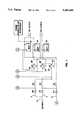
- FIG. 2describes an alternate preferred embodiment to the present invention in which a battery charging circuit which takes its power from AC mains 40, 41 is provided.
- DC charging currentis provided by taking the AC mains power through step-down transformer T1 and rectifying the power to provide rectified DC current.
- a center tapped full wave rectifier 42is used to provide the main charging current through SCR1 and SCR2. Additional DC current is provided through a center tap full wave rectifier by means of diodes D1 and D2 to provide switching current to control relay coils K3, K4 and K5.
- FIG. 2is connected to the circuit described above in the first preferred embodiment, as shown in FIG. 1 through connections A, B, C, D and E.
- the charging current in this alternate preferred embodimentis taken from a battery charger circuit powered from the AC mains 40.
- a unique feature of the charging circuitis the ability to charge the primary battery using charging parameters specific to lead acid batteries and the auxiliary batteries using charging parameters specific to deep cycle marine batteries.
- the charging circuits of FIG. 2are designed to prevent overcharging of the respective batteries by removing the charging current when the batteries reach their optimal operating voltages. Since the main and auxiliary batteries have differing optimal operating voltages indicating a full charge, separate charging sense circuits are used to determine when a full charge is obtained on the main (lead acid) or auxiliary (deep cycle) batteries.
- the electrical components within dashed portion 200 of FIG. 2are the components of the battery charging circuit for the deep cycle auxiliary batteries.
- the portion of the circuitry of FIG. 2 inside dashed box 202comprise the charging circuit for the main (lead acid) battery.
- Deep cycle batterieshave an optimal charging voltage of approximately 14 volts. Once fully charged, a battery will typically discharge a moderate amount based on internal resistance, leakage current and the like.
- the circuitry 200 of the charging circuit of FIG. 2 for the auxiliary batteriesis designed to sense when the auxiliary batteries are fully charged and then to interrupt the charging current. In order that the charging circuit 200 of FIG. 2 does not reapply the charging current too soon or too often (typically in an oscillation mode) a hysteresis or window of voltage ranges is used to ensure that the battery charging circuit 200 does not provide additional charging current of the auxiliary batteries unless the voltage drops below 12.75 volts.
- the charging circuit 200 of FIG. 2has an upper threshold for interrupting the charging current of 14.25 volts and it will not reapply the charging current unless the voltage of the auxiliary batteries drops below 12.75 volts.
- relay K1is used to control the triggers of SCR1 and SCR2 to interrupt the main charging current for all batteries. Since the fully charged voltage of the main (lead acid) battery is lower than the fully charged voltage of the auxiliary (deep cycle) batteries, interrupting the main charging voltage through SCR1 and SCR2 when the optimal charging voltage of the auxiliary (deep cycle) batteries is achieved will only occur after the main battery (lead acid) has been fully charged.
- Relay coil K1is primarily controlled by IC2 which in the preferred embodiment is part no. LM555 available from National Semiconductor and other vendors.
- IC2is an off-the-shelf standard 555 timer well known to those skilled in art. It is wired according to manufacturers specifications in FIG. 2 to operate in bistable mode.
- IC2is an off-the-shelf standard 555 timer well known to those skilled in art. It is wired according to manufacturers specifications in FIG. 2 to operate in bistable mode.
- IC2 operating in bistable modeis controlled by comparators IC1a and IC1b which are, in the preferred embodiment, part number LM339 available from National Semiconductor and other vendors.
- the comparatorssense the voltage on the auxiliary batteries and operate to remove the charging current when the upper cutoff voltage is reached by the batteries. The comparators will then not reapply the charging current to the auxiliary batteries unless and until the voltage drops below 12.75 volts.
- Comparator IC1acompares a reference voltage on the noninverting input to the sensed voltage on the auxiliary batteries when in charging mode. In charging mode, as described above, the batteries are all placed in parallel for charging.
- Comparator IC1acompares a reference voltage to the voltage on the output of the center-tapped, full-wave rectifier which is directly connected to the positive terminals of the main and auxiliary batteries configured in parallel.
- the reference voltageis determined by Zener Diode Z1 and the voltage ladder across resisters R5, R6 and R7.
- the reference voltage applied to IC1a on the noninverting inputis compared to the voltage on the output of the center tapped full wave rectifier of FIG. 2 through another voltage ladder R3, R4, which is directly connected to the positive terminals of the batteries when configured in parallel for charging.
- the comparator IC1awill sense the upper threshold of charge voltage and interrupt the charging current when that threshold is reached.
- comparator IC1bcompares a reference voltage determined from resistance ladder R5, R6 and R7 applied to the noninverting input of comparator IC1b to the voltage on the auxiliary batteries through resistance ladder R3, R4. Since the same resistance ladder R5, R6, R7 is used to determine the threshold voltages for both IC1a and IC1b the reference voltage drift will track with both comparators resulting in no common mode error drift due to temperature variation.
- the cutoff voltage for comparator IC1b in the preferred embodiment of the present inventionis 12.75 volts.
- IC2operating as a bistable latch, will close the relay contacts for relay K1 upon comparator IC1b sensing that the voltage across the auxiliary batteries configured for charging is less than 12.75 volts.
- comparator IC1awill sense the voltage threshold and cause bistable circuit IC2 to open relay K1 to interrupt the charging current.
- the charging current control circuit for the main batteryis shown in dashed portion 202 of FIG. 2.
- the circuit configuration for controlling the main battery 202is similar to the configuration of the circuitry for the auxiliary charging circuit 200.
- Comparator IC1c and IC1dreceive reference voltages from a resistance ladder comprising resistors R12, R13 and R14. Comparators IC1c and IC1d take different reference voltages off different points along the voltage ladder circuit.
- IC3is also an LM555 timer operating in the bistable mode for controlling relay K2.
- Relay K2controls the main battery charging current for the battery circuitry in the lower half of FIG. 2.
- Relay K2includes a diode D4 which is a back EMF diode, to protect IC3 when relay coil K2 is opened.
- the resistive ladder comprising resistors R12, R13 and R14have a fixed voltage reference applied to it through Zener Diode Z2.
- Comparator IC1csenses the voltage threshold of 13.5 volts on the main battery and interrupts the charging current to prevent the overcharging or boiling of the main (lead acid) battery. IC1c is used to cause bistable latch IC3 to apply current to the charging circuits in the lower half of FIG. 2 connected through A, B, C, D and E. Comparator IC1d compares the voltage set at a different point along voltage ladder R12, R13 and R14 for the chosen threshold voltage at 12.6 volts on the main battery.
- IC1dis the lower threshold for the operating window of the circuit 202, of FIG. 2, for charging the main battery in parallel with the auxiliary batteries.
- Comparator IC1dserves to change the state of bistable timer circuit IC3 to close relay K2 to apply the charging current when main battery voltage drops below 12.6 volts.
- the circuits 200, 202 of FIG. 2show an automatic means for charging both deep discharge auxiliary batteries and main lead acid batteries of a boat or the like.
- circuit IC3is used to control relay K2 to apply or interrupt charging current for the main battery.
- Relay contact K2serves as a master to control the closing of relay K3 through the relay coil K3, shown in FIG. 1.
- the energization of relay coil K3causes the relay contact K3 to apply the charging current to the main batteries and auxiliary batteries configured in parallel for charging.
- Relay contact K2will open when circuit 202 senses the voltage on the main battery at 13.5 volts.
- the opening of relay contact K2will in turn open relay contact K3 removing the main charging current from the main battery only.
- the opening of relay contact K2will not interrupt the charging current applied to the auxiliary batteries.
- the charging current for the auxiliary batteriesis controlled by circuit 200 which is configured to have a higher cutoff voltage than that of circuit 202.
- auxiliary batteriesCharging current remains on the auxiliary batteries when the voltage on the auxiliary batteries is between 13.5 volts (the cutoff voltage for the main battery) and 14.25 (the cutoff voltage of the auxiliary deep discharge batteries) in a preferred embodiment.
- relay contact K4 and K5are in a normally open position due to the energization of relay coils K4 and K5. These relay coils are energized automatically by applying main voltage to the AC input to transformer T1.
- the energization of coils K4 and K5cause the auxiliary batteries B1 and B2 to be configured in a parallel configuration for charging.
- relay contacts K4 and K5move to the normally closed position due to the de-energization of relay coils K4 and K5.
- the batteriesare automatically configured into a series connection resulting in an overall voltage of 24 volts, which is the preferred voltage for a trolling motor or the like.
- the batteriesneed not be placed in a series configuration if a trolling motor or the like requires 12 volts AC output.
Landscapes
- Engineering & Computer Science (AREA)
- Power Engineering (AREA)
- Charge And Discharge Circuits For Batteries Or The Like (AREA)
Abstract
Description
______________________________________ Parts List REF COMPONENT DESIG- ATTRI- NAME NATOR VALUE BUTES ______________________________________ Capacitor, Disc C1 .1 ufd/35 v Capacitor, Disc C2 .1 ufd/35v COMPARATOR IC1a 1/4LM339 COMPARATOR IC1b 1/4LM339 COMPARATOR IC1c 1/4LM339 COMPARATOR IC1d 1/4 LM339 Diode D2 1N4001 Diode D1 1N4001 Diode D3 1N4001 Diode D4 1N4001 Diode D5 1N4001 Diode D7 1N4001 Diode D6 1N4001 Diode, Zener Z1 5.1 V/500 MW 1N751A or 1N4689 Diode, Zener Z2 5.1 V/500 MW 1N751A or 1N4689 NEG.BM # 12 AWG/ZIP NEG.B1 # 12 AWG/ZIP NEG.B2 # 12 AWG/ZIP NEG. 12V. OUTPUT 5/16" STUD NEG. 24V. OUTPUT 5/16" STUD POS.BM # 12 AWG/ZIP POS.B1 # 12 AWG/ZIP POS.B2 # 12 AWG/ZIP POS. 12V. OUTPUT 3/8" STUD POS. 24V. OUTPUT 3/8" STUDPOWER CORD PC1 3 COND. #14AWG RELAY K3 12 V/30A RELAY K4 12 V/30A RELAY K5 12 V/30 A RELAY,REED K1 12 V/.75 A RELAY,REED K2 12 V/.75 A Resistor R1 33 ohm/1/4 w Resistor R2 33 ohm/1/4 w Resistor R5 1.8 K/1/4 W Resistor R7 43 K/1/4 W/5% Resistor R6 5.1 K/1/4 W/5% Resistor R9 10 K/1/4 W Resistor R8 10 K/1/4 W Resistor R12 1.8 K/1/4 W Resistor R14 43 K/1/4 W/5% Resistor R13 3.6 K/1/4 W/5% Resistor R16 10 K/14/W Resistor R15 10 K/1/4 W Resistor R3 33 K/1/4 W/5% Resistor R4 18 K/1/4 W/5% Resistor R10 33 K/1/4 W/5% Resistor R11 20 K/1/4 W/5% SCR SCR1 MCR225 SCR SCR2 MCR225 TIMER IC2 LM555 ______________________________________
Claims (18)
Priority Applications (1)
| Application Number | Priority Date | Filing Date | Title |
|---|---|---|---|
| US08/080,324US5418444A (en) | 1993-06-22 | 1993-06-22 | Automatic battery charge and discharge control system |
Applications Claiming Priority (1)
| Application Number | Priority Date | Filing Date | Title |
|---|---|---|---|
| US08/080,324US5418444A (en) | 1993-06-22 | 1993-06-22 | Automatic battery charge and discharge control system |
Publications (1)
| Publication Number | Publication Date |
|---|---|
| US5418444Atrue US5418444A (en) | 1995-05-23 |
Family
ID=22156673
Family Applications (1)
| Application Number | Title | Priority Date | Filing Date |
|---|---|---|---|
| US08/080,324Expired - Fee RelatedUS5418444A (en) | 1993-06-22 | 1993-06-22 | Automatic battery charge and discharge control system |
Country Status (1)
| Country | Link |
|---|---|
| US (1) | US5418444A (en) |
Cited By (33)
| Publication number | Priority date | Publication date | Assignee | Title |
|---|---|---|---|---|
| US5767658A (en)* | 1996-11-18 | 1998-06-16 | Gnb Technologies, Inc. | Battery power system for a vehicle |
| US5896022A (en)* | 1996-12-13 | 1999-04-20 | Jacobs, Sr.; John T. | Battery charge managing system |
| ES2128943A1 (en)* | 1995-06-22 | 1999-05-16 | Glorywin Int Group Ltd | Vehicle dual battery controller utilizing motion sensor |
| GB2292274B (en)* | 1994-08-11 | 1999-07-07 | Iain Wallace Waugh | A battery controller |
| US5977744A (en)* | 1996-10-26 | 1999-11-02 | Lucas Industries | Vehicle battery controller |
| US5986431A (en)* | 1996-11-18 | 1999-11-16 | Gnb Technologies, Inc. | Battery power system for vehicles |
| US5993992A (en)* | 1997-06-25 | 1999-11-30 | Norvik Traction Inc. | Battery pack with connecting battery modules |
| GB2302622B (en)* | 1995-06-22 | 2000-03-29 | Glorywin Int Group Ltd | Battery controller |
| US6194872B1 (en) | 1999-06-25 | 2001-02-27 | Dell Usa, L.P. | Method and system for battery isolation during shipment |
| EP0981195A3 (en)* | 1998-08-20 | 2001-05-23 | GUNTON, Bruce Stanley | Control arrangement for aperture closures |
| EP1126575A3 (en)* | 2000-02-17 | 2003-05-14 | Visteon Global Technologies, Inc. | Electrical charging system |
| WO2003023936A3 (en)* | 2001-09-10 | 2003-10-16 | Johnson Controls Tech Co | Energy management system for vehicle |
| US6815931B1 (en) | 2002-05-31 | 2004-11-09 | John T. Wells | Marine charge source switching system |
| US20050035740A1 (en)* | 2003-08-11 | 2005-02-17 | Reserve Power Cell, Llc | Multiple battery system and network controlled multiple battery system |
| US20050035741A1 (en)* | 2003-08-11 | 2005-02-17 | David Elder | Multiple battery management system, auxiliary battery attachment system, and network controlled multiple battery system |
| US20050156567A1 (en)* | 2004-01-20 | 2005-07-21 | Campagnolo S.R.L. | Rechargeable electrical power supply unit for an electronic device of a bicycle |
| US7009350B1 (en)* | 2004-02-13 | 2006-03-07 | Great Systems, Inc. | Energy collection and storage system |
| US7193393B1 (en) | 2001-10-26 | 2007-03-20 | Payne James C | Approach for charging multiple batteries |
| US20070159007A1 (en)* | 2006-01-09 | 2007-07-12 | General Electric Company | Energy storage system for electric or hybrid vehicle |
| US20070229032A1 (en)* | 2006-07-14 | 2007-10-04 | David Elder | Battery monitoring, warranty, and performance tracking system |
| US20090309540A1 (en)* | 2005-03-30 | 2009-12-17 | David Elder | Method of operating a networl with a programmable battery and programming same |
| US20110025124A1 (en)* | 2009-07-31 | 2011-02-03 | Ladislaus Joseph Brabec | Bi-directional battery voltage converter |
| US8111036B2 (en) | 2006-03-27 | 2012-02-07 | Stephen George Rosenstock | System for electrically connecting and disconnecting a vehicle generator from a vehicle storage unit |
| US20130076519A1 (en)* | 2011-09-27 | 2013-03-28 | Chi Mei Communication Systems, Inc. | Apparatus and method for controlling charging and discharging of batteries |
| WO2016075616A2 (en) | 2014-11-10 | 2016-05-19 | Awelco Inc. Production S.P.A. | Aid module for electrically starting an internal combustion engine |
| US20160153418A1 (en)* | 2014-11-28 | 2016-06-02 | Fujitsu Ten Limited | Power supply device for vehicle |
| CN106849233A (en)* | 2017-02-06 | 2017-06-13 | 全球能源互联网欧洲研究院 | A kind of centralized charge-discharge system, control method and device |
| US9821737B2 (en) | 2015-04-30 | 2017-11-21 | Cnh Industrial Americal Llc | Isolation of auxiliary electronics battery from starting battery |
| US20180134175A1 (en)* | 2016-11-16 | 2018-05-17 | Hyundai Autron Co., Ltd. | Apparatus and method for preventing over-charging of battery |
| CN113492722A (en)* | 2020-03-18 | 2021-10-12 | 本田技研工业株式会社 | Power supply system for vehicle |
| US11155173B2 (en)* | 2018-12-26 | 2021-10-26 | Toyota Jidosha Kabushiki Kaisha | Electric vehicle |
| US11190026B2 (en)* | 2014-09-30 | 2021-11-30 | Cps Technology Holdings Llc | Battery system to be deployed in a vehicle having a first battery and a second battery, battery control unit to be deployed in a battery system of a vehicle, and method related to the same |
| WO2023107125A1 (en)* | 2021-12-12 | 2023-06-15 | Zf Active Safety And Electronics Us Llc. | Connection device for a control unit for a vehicle |
Citations (17)
| Publication number | Priority date | Publication date | Assignee | Title |
|---|---|---|---|---|
| US3258670A (en)* | 1966-06-28 | Charging and discharging the same | ||
| US3457491A (en)* | 1966-07-11 | 1969-07-22 | Conrad Nagel Black | Remote load or battery control system |
| US3718848A (en)* | 1971-03-29 | 1973-02-27 | Outboard Marine Corp | Series-parallel battery system and switch therefore |
| US3763415A (en)* | 1968-12-02 | 1973-10-02 | C Ownby | Automatic battery charging control device and apparatus |
| US4004208A (en)* | 1973-12-17 | 1977-01-18 | Pentti Juuse Tamminen | Starting aid and reserve light for vehicles |
| US4081738A (en)* | 1975-08-25 | 1978-03-28 | G & R Industries, Inc. | Plural battery control apparatus |
| US4082992A (en)* | 1977-01-18 | 1978-04-04 | Day Oliver E | Twin ignition and twin electrical start system for a vehicle |
| US4114082A (en)* | 1977-07-05 | 1978-09-12 | Scheidler Ralph E | Dual voltage battery system and electronic switch therefor |
| US4264855A (en)* | 1978-07-26 | 1981-04-28 | Centro Ricerche Fiat S.P.A. | Electrical power supply equipment for motor vehicles |
| US4281277A (en)* | 1979-08-10 | 1981-07-28 | General Motors Corporation | Dual secondary cell charging system |
| US4649332A (en)* | 1985-08-26 | 1987-03-10 | Bell Stuart D | Trolling motor battery connector system |
| US4959554A (en)* | 1989-05-08 | 1990-09-25 | Underwood Iv Joseph W T | Dual input-dual output electric switch |
| US5051548A (en)* | 1989-05-08 | 1991-09-24 | Wood 'n Rock, A Florida Partnership | Dual input-dual output electric switch |
| US5111132A (en)* | 1989-04-18 | 1992-05-05 | Sanshin Kogyo Kabushiki Kaisha | Battery charging system for marine propulsion unit |
| JPH04261343A (en)* | 1991-02-08 | 1992-09-17 | Sanshin Ind Co Ltd | Battery charger for ship propeller |
| US5164655A (en)* | 1991-08-05 | 1992-11-17 | Dimensions Unlimited, Inc. | 12-24 volt power system |
| US5225761A (en)* | 1992-01-15 | 1993-07-06 | Wells Marine Technology, Inc. | Battery management system |
- 1993
- 1993-06-22USUS08/080,324patent/US5418444A/ennot_activeExpired - Fee Related
Patent Citations (18)
| Publication number | Priority date | Publication date | Assignee | Title |
|---|---|---|---|---|
| US3258670A (en)* | 1966-06-28 | Charging and discharging the same | ||
| US3457491A (en)* | 1966-07-11 | 1969-07-22 | Conrad Nagel Black | Remote load or battery control system |
| US3763415A (en)* | 1968-12-02 | 1973-10-02 | C Ownby | Automatic battery charging control device and apparatus |
| US3718848A (en)* | 1971-03-29 | 1973-02-27 | Outboard Marine Corp | Series-parallel battery system and switch therefore |
| US4004208A (en)* | 1973-12-17 | 1977-01-18 | Pentti Juuse Tamminen | Starting aid and reserve light for vehicles |
| US4081738A (en)* | 1975-08-25 | 1978-03-28 | G & R Industries, Inc. | Plural battery control apparatus |
| US4082992A (en)* | 1977-01-18 | 1978-04-04 | Day Oliver E | Twin ignition and twin electrical start system for a vehicle |
| US4114082A (en)* | 1977-07-05 | 1978-09-12 | Scheidler Ralph E | Dual voltage battery system and electronic switch therefor |
| US4264855A (en)* | 1978-07-26 | 1981-04-28 | Centro Ricerche Fiat S.P.A. | Electrical power supply equipment for motor vehicles |
| US4281277A (en)* | 1979-08-10 | 1981-07-28 | General Motors Corporation | Dual secondary cell charging system |
| US4649332A (en)* | 1985-08-26 | 1987-03-10 | Bell Stuart D | Trolling motor battery connector system |
| US5111132A (en)* | 1989-04-18 | 1992-05-05 | Sanshin Kogyo Kabushiki Kaisha | Battery charging system for marine propulsion unit |
| US4959554A (en)* | 1989-05-08 | 1990-09-25 | Underwood Iv Joseph W T | Dual input-dual output electric switch |
| US5051548A (en)* | 1989-05-08 | 1991-09-24 | Wood 'n Rock, A Florida Partnership | Dual input-dual output electric switch |
| JPH04261343A (en)* | 1991-02-08 | 1992-09-17 | Sanshin Ind Co Ltd | Battery charger for ship propeller |
| US5233282A (en)* | 1991-02-08 | 1993-08-03 | Sanshin Kogyo Kabushiki Kaisha | Battery system for marine propulsion unit |
| US5164655A (en)* | 1991-08-05 | 1992-11-17 | Dimensions Unlimited, Inc. | 12-24 volt power system |
| US5225761A (en)* | 1992-01-15 | 1993-07-06 | Wells Marine Technology, Inc. | Battery management system |
Cited By (66)
| Publication number | Priority date | Publication date | Assignee | Title |
|---|---|---|---|---|
| GB2292274B (en)* | 1994-08-11 | 1999-07-07 | Iain Wallace Waugh | A battery controller |
| GB2302622B (en)* | 1995-06-22 | 2000-03-29 | Glorywin Int Group Ltd | Battery controller |
| ES2128943A1 (en)* | 1995-06-22 | 1999-05-16 | Glorywin Int Group Ltd | Vehicle dual battery controller utilizing motion sensor |
| US5977744A (en)* | 1996-10-26 | 1999-11-02 | Lucas Industries | Vehicle battery controller |
| US5986431A (en)* | 1996-11-18 | 1999-11-16 | Gnb Technologies, Inc. | Battery power system for vehicles |
| US5767658A (en)* | 1996-11-18 | 1998-06-16 | Gnb Technologies, Inc. | Battery power system for a vehicle |
| US5896022A (en)* | 1996-12-13 | 1999-04-20 | Jacobs, Sr.; John T. | Battery charge managing system |
| US5993992A (en)* | 1997-06-25 | 1999-11-30 | Norvik Traction Inc. | Battery pack with connecting battery modules |
| EP0981195A3 (en)* | 1998-08-20 | 2001-05-23 | GUNTON, Bruce Stanley | Control arrangement for aperture closures |
| US6194872B1 (en) | 1999-06-25 | 2001-02-27 | Dell Usa, L.P. | Method and system for battery isolation during shipment |
| EP1126575A3 (en)* | 2000-02-17 | 2003-05-14 | Visteon Global Technologies, Inc. | Electrical charging system |
| WO2003023936A3 (en)* | 2001-09-10 | 2003-10-16 | Johnson Controls Tech Co | Energy management system for vehicle |
| US20050029867A1 (en)* | 2001-09-10 | 2005-02-10 | Wood Steven J. | Energy management system for vehicle |
| US7193393B1 (en) | 2001-10-26 | 2007-03-20 | Payne James C | Approach for charging multiple batteries |
| US6815931B1 (en) | 2002-05-31 | 2004-11-09 | John T. Wells | Marine charge source switching system |
| US7388349B2 (en)* | 2003-08-11 | 2008-06-17 | Reserve Power Cell, Llc | Multiple battery switching method and apparatus |
| US7834583B2 (en) | 2003-08-11 | 2010-11-16 | Reserve Power Cell, Llc | Remotely controlled multiple battery system |
| US7679314B2 (en) | 2003-08-11 | 2010-03-16 | Reserve Power Cell, Llc | Multiple battery system for reliably supplying electrical energy to an electrical system |
| US7675261B2 (en) | 2003-08-11 | 2010-03-09 | Reserve Power Cell, Llc | Auxiliary battery attachment apparatus for use in a multiple battery system that reliably supplies electrical energy to an electrical system |
| US20050035740A1 (en)* | 2003-08-11 | 2005-02-17 | Reserve Power Cell, Llc | Multiple battery system and network controlled multiple battery system |
| US20050035737A1 (en)* | 2003-08-11 | 2005-02-17 | Whodathought Holdings, Inc. | [Multiple Battery System and Auxiliary Battery Attachment System] |
| US7567057B2 (en) | 2003-08-11 | 2009-07-28 | Reserve Power Cell, Llc | Multiple battery management system, auxiliary battery attachment system, and network controlled multiple battery system |
| US8120364B2 (en) | 2003-08-11 | 2012-02-21 | Reserve Power Cell, Llc | Stand alone battery monitoring system with alert |
| US7839117B2 (en) | 2003-08-11 | 2010-11-23 | Reserve Power Cell, Llc | System and method of detecting a battery fault |
| US7339347B2 (en) | 2003-08-11 | 2008-03-04 | Reserve Power Cell, Llc | Apparatus and method for reliably supplying electrical energy to an electrical system |
| US20080111557A1 (en)* | 2003-08-11 | 2008-05-15 | Reserve Power Cell, Llc | Method for detecting a discharge condition fault in an electrical system of a vehicle or piece of machinery |
| US20080111427A1 (en)* | 2003-08-11 | 2008-05-15 | Reserve Power Cell, Llc | Auxiliary battery attachment apparatus for use in a multiple battery system that reliably supplies electrical energy to an electrical system |
| US20100076706A1 (en)* | 2003-08-11 | 2010-03-25 | David Elder | Stand alone battery monitoring system with alert |
| US7427865B2 (en) | 2003-08-11 | 2008-09-23 | Reserve Power Cell, Llc | Method for detecting a discharge condition fault in an electrical system of a vehicle or piece of machinery |
| US20050035741A1 (en)* | 2003-08-11 | 2005-02-17 | David Elder | Multiple battery management system, auxiliary battery attachment system, and network controlled multiple battery system |
| US20080315837A1 (en)* | 2003-08-11 | 2008-12-25 | David Elder | Remotely controlled multiple battery system |
| US20080238367A1 (en)* | 2004-01-20 | 2008-10-02 | Campagnolo S.R.L. | Rechargeable electrical power supply unit for an electronic device of a bicycle |
| EP1557926A1 (en)* | 2004-01-20 | 2005-07-27 | Campagnolo S.R.L. | Rechargeable electrical power supply unit for an electronic device of a bicycle |
| US20050156567A1 (en)* | 2004-01-20 | 2005-07-21 | Campagnolo S.R.L. | Rechargeable electrical power supply unit for an electronic device of a bicycle |
| US7205732B1 (en)* | 2004-02-13 | 2007-04-17 | Great Systems, Inc. | Energy collection and storage system |
| US7009350B1 (en)* | 2004-02-13 | 2006-03-07 | Great Systems, Inc. | Energy collection and storage system |
| US20090309540A1 (en)* | 2005-03-30 | 2009-12-17 | David Elder | Method of operating a networl with a programmable battery and programming same |
| US20070159007A1 (en)* | 2006-01-09 | 2007-07-12 | General Electric Company | Energy storage system for electric or hybrid vehicle |
| US7489048B2 (en)* | 2006-01-09 | 2009-02-10 | General Electric Company | Energy storage system for electric or hybrid vehicle |
| USRE45431E1 (en)* | 2006-01-09 | 2015-03-24 | General Electric Company | Energy storage system for electric or hybrid vehicle |
| USRE43956E1 (en)* | 2006-01-09 | 2013-02-05 | General Electric Company | Energy storage system for electric or hybrid vehicle |
| US8111036B2 (en) | 2006-03-27 | 2012-02-07 | Stephen George Rosenstock | System for electrically connecting and disconnecting a vehicle generator from a vehicle storage unit |
| US20070229032A1 (en)* | 2006-07-14 | 2007-10-04 | David Elder | Battery monitoring, warranty, and performance tracking system |
| US8013611B2 (en) | 2006-07-14 | 2011-09-06 | Reserve Power Cell, Llc | Vehicle battery product and battery monitoring system |
| US9102241B2 (en) | 2009-07-31 | 2015-08-11 | Thermo King Corporation | Bi-directional battery voltage converter |
| US20110025124A1 (en)* | 2009-07-31 | 2011-02-03 | Ladislaus Joseph Brabec | Bi-directional battery voltage converter |
| US9694697B2 (en) | 2009-07-31 | 2017-07-04 | Thermo King Corporation | Bi-directional battery voltage converter |
| US8441228B2 (en) | 2009-07-31 | 2013-05-14 | Thermo King Corporation | Bi-directional battery voltage converter |
| US8541905B2 (en) | 2009-07-31 | 2013-09-24 | Thermo King Corporation | Bi-directional battery voltage converter |
| US20110025126A1 (en)* | 2009-07-31 | 2011-02-03 | Ladislaus Joseph Brabec | Bi-directional battery voltage converter |
| US9199543B2 (en) | 2009-07-31 | 2015-12-01 | Thermo King Corporation | Bi-directional battery voltage converter |
| US20110025125A1 (en)* | 2009-07-31 | 2011-02-03 | Ladislaus Joseph Brabec | Bi-directional battery voltage converter |
| US9077187B2 (en)* | 2011-09-27 | 2015-07-07 | Shenzhen Futaihong Precision Industry Co., Ltd. | Apparatus and method for controlling charging and discharging of batteries |
| US20130076519A1 (en)* | 2011-09-27 | 2013-03-28 | Chi Mei Communication Systems, Inc. | Apparatus and method for controlling charging and discharging of batteries |
| US11190026B2 (en)* | 2014-09-30 | 2021-11-30 | Cps Technology Holdings Llc | Battery system to be deployed in a vehicle having a first battery and a second battery, battery control unit to be deployed in a battery system of a vehicle, and method related to the same |
| WO2016075616A2 (en) | 2014-11-10 | 2016-05-19 | Awelco Inc. Production S.P.A. | Aid module for electrically starting an internal combustion engine |
| US20160153418A1 (en)* | 2014-11-28 | 2016-06-02 | Fujitsu Ten Limited | Power supply device for vehicle |
| US9797361B2 (en)* | 2014-11-28 | 2017-10-24 | Fujitsu Ten Limited | Power supply device for vehicle |
| US9821737B2 (en) | 2015-04-30 | 2017-11-21 | Cnh Industrial Americal Llc | Isolation of auxiliary electronics battery from starting battery |
| US10414285B2 (en)* | 2016-11-16 | 2019-09-17 | Hyundai Autron Co., Ltd. | Apparatus and method for preventing over-charging of battery |
| US20180134175A1 (en)* | 2016-11-16 | 2018-05-17 | Hyundai Autron Co., Ltd. | Apparatus and method for preventing over-charging of battery |
| CN106849233A (en)* | 2017-02-06 | 2017-06-13 | 全球能源互联网欧洲研究院 | A kind of centralized charge-discharge system, control method and device |
| US11155173B2 (en)* | 2018-12-26 | 2021-10-26 | Toyota Jidosha Kabushiki Kaisha | Electric vehicle |
| CN113492722A (en)* | 2020-03-18 | 2021-10-12 | 本田技研工业株式会社 | Power supply system for vehicle |
| CN113492722B (en)* | 2020-03-18 | 2024-04-26 | 本田技研工业株式会社 | Vehicle power system |
| WO2023107125A1 (en)* | 2021-12-12 | 2023-06-15 | Zf Active Safety And Electronics Us Llc. | Connection device for a control unit for a vehicle |
Similar Documents
| Publication | Publication Date | Title |
|---|---|---|
| US5418444A (en) | Automatic battery charge and discharge control system | |
| US7564223B2 (en) | High frequency battery charger and method of operating same | |
| AU596341B2 (en) | A universal battery charging system and method | |
| US6057666A (en) | Method and circuit for controlling charging in a dual battery electrical system | |
| US5200690A (en) | Quick charge control apparatus and control method thereof | |
| US4114082A (en) | Dual voltage battery system and electronic switch therefor | |
| EP1552591B1 (en) | High frequency battery charger and method of operating same | |
| CA1211186A (en) | Alternator load shedder for engine starting improvement | |
| US4035709A (en) | Battery charging system | |
| US4127803A (en) | Charging circuit for an auxiliary battery on an electrically-propelled vehicle | |
| EP0652620B1 (en) | Method of equalizing the voltage across drive batteries connected in series during recharging, for electric vehicles, and a device for implementing the method | |
| EP1025632B1 (en) | Method and circuit for controlling charging in a dual battery electrical system | |
| JPH0260433A (en) | power supply | |
| US5739668A (en) | Charging control systems and circuits for recharging automobile batteries | |
| US4010410A (en) | Recreational vehicle converter-battery fast charging circuit | |
| US4136311A (en) | Dual rate voltage regulator | |
| KR0174121B1 (en) | Voltage regulator for vehicle alternator | |
| JPH10108379A (en) | Charging control system for electric vehicle | |
| JPS63316643A (en) | Charging circuit | |
| SU790089A1 (en) | Device for automatic reenergization of electric motor | |
| JPH04281334A (en) | Quick charger | |
| JPS6033717Y2 (en) | Charging generator control device | |
| JP2918755B2 (en) | Charge control device | |
| SU1525802A2 (en) | Device for protecting three-phase motor from phase-fault operation | |
| JPS6349083Y2 (en) |
Legal Events
| Date | Code | Title | Description |
|---|---|---|---|
| AS | Assignment | Owner name:GOLDENEYE PRODUCTS, INC., MINNESOTA Free format text:ASSIGNMENT OF ASSIGNORS INTEREST;ASSIGNORS:COOK, GARY I.;NELSON, BRUCE D.;REEL/FRAME:006774/0693 Effective date:19930825 | |
| AS | Assignment | Owner name:P & L ASSOCIATES, MINNESOTA Free format text:SECURITY INTEREST;ASSIGNOR:GOLDENEYE PRODUCTS, INC.;REEL/FRAME:008842/0217 Effective date:19970211 | |
| FEPP | Fee payment procedure | Free format text:PAT HLDR NO LONGER CLAIMS SMALL ENT STAT AS SMALL BUSINESS (ORIGINAL EVENT CODE: LSM2); ENTITY STATUS OF PATENT OWNER: LARGE ENTITY | |
| FEPP | Fee payment procedure | Free format text:PAYOR NUMBER ASSIGNED (ORIGINAL EVENT CODE: ASPN); ENTITY STATUS OF PATENT OWNER: LARGE ENTITY | |
| AS | Assignment | Owner name:DONALD W. STICKSEL PLL ASSOCIATES, MINNESOTA Free format text:SECURITY AGREEMENT;ASSIGNOR:GOLDENEYE PRODUCTS, INC.;REEL/FRAME:008933/0273 Effective date:19970211 | |
| FPAY | Fee payment | Year of fee payment:4 | |
| AS | Assignment | Owner name:GOLDENEYE PRODUCTS, INC, MINNESOTA Free format text:ASSIGNMENT OF ASSIGNORS INTEREST;ASSIGNOR:P & L ASSOCIATES, A MINNESOTA SOLE PROPRIETORSHIP OWNED BY STICKEL, DONALD W.;REEL/FRAME:009845/0161 Effective date:19980605 | |
| REMI | Maintenance fee reminder mailed | ||
| LAPS | Lapse for failure to pay maintenance fees | ||
| STCH | Information on status: patent discontinuation | Free format text:PATENT EXPIRED DUE TO NONPAYMENT OF MAINTENANCE FEES UNDER 37 CFR 1.362 | |
| FP | Lapsed due to failure to pay maintenance fee | Effective date:20030523 |