US5418372A - Intraoperative electron beam therapy system and facility - Google Patents
Intraoperative electron beam therapy system and facilityDownload PDFInfo
- Publication number
- US5418372A US5418372AUS08/258,569US25856994AUS5418372AUS 5418372 AUS5418372 AUS 5418372AUS 25856994 AUS25856994 AUS 25856994AUS 5418372 AUS5418372 AUS 5418372A
- Authority
- US
- United States
- Prior art keywords
- electron beam
- housing
- therapy system
- source
- beam therapy
- Prior art date
- Legal status (The legal status is an assumption and is not a legal conclusion. Google has not performed a legal analysis and makes no representation as to the accuracy of the status listed.)
- Expired - Lifetime
Links
- 238000010894electron beam technologyMethods0.000titleclaimsabstractdescription59
- 238000002560therapeutic procedureMethods0.000titleclaimsabstractdescription25
- 238000001816coolingMethods0.000claimsdescription2
- 230000005855radiationEffects0.000description17
- 238000000034methodMethods0.000description5
- 206010028980NeoplasmDiseases0.000description4
- 238000013461designMethods0.000description3
- 239000011888foilSubstances0.000description3
- 206010039491SarcomaDiseases0.000description2
- 238000013459approachMethods0.000description2
- 229910052790berylliumInorganic materials0.000description2
- ATBAMAFKBVZNFJ-UHFFFAOYSA-Nberyllium atomChemical compound[Be]ATBAMAFKBVZNFJ-UHFFFAOYSA-N0.000description2
- 230000005540biological transmissionEffects0.000description2
- 238000009826distributionMethods0.000description2
- 239000011521glassSubstances0.000description2
- 238000012986modificationMethods0.000description2
- 230000004048modificationEffects0.000description2
- 238000012544monitoring processMethods0.000description2
- 238000001959radiotherapyMethods0.000description2
- 238000001356surgical procedureMethods0.000description2
- 210000001519tissueAnatomy0.000description2
- 206010002091AnaesthesiaDiseases0.000description1
- 230000005461BremsstrahlungEffects0.000description1
- 208000001333Colorectal NeoplasmsDiseases0.000description1
- UFHFLCQGNIYNRP-UHFFFAOYSA-NHydrogenChemical compound[H][H]UFHFLCQGNIYNRP-UHFFFAOYSA-N0.000description1
- 206010061902Pancreatic neoplasmDiseases0.000description1
- 208000007660Residual NeoplasmDiseases0.000description1
- 208000005718Stomach NeoplasmsDiseases0.000description1
- RTAQQCXQSZGOHL-UHFFFAOYSA-NTitaniumChemical compound[Ti]RTAQQCXQSZGOHL-UHFFFAOYSA-N0.000description1
- 238000010521absorption reactionMethods0.000description1
- 230000037005anaesthesiaEffects0.000description1
- 210000000988bone and boneAnatomy0.000description1
- 206010006007bone sarcomaDiseases0.000description1
- 239000000356contaminantSubstances0.000description1
- 238000011347external beam therapyMethods0.000description1
- 229910052739hydrogenInorganic materials0.000description1
- 239000001257hydrogenSubstances0.000description1
- 208000015181infectious diseaseDiseases0.000description1
- 238000009434installationMethods0.000description1
- 238000004519manufacturing processMethods0.000description1
- 239000000463materialSubstances0.000description1
- 238000013160medical therapyMethods0.000description1
- 230000035515penetrationEffects0.000description1
- 229920003223poly(pyromellitimide-1,4-diphenyl ether)Polymers0.000description1
- 239000013589supplementSubstances0.000description1
- 239000010936titaniumSubstances0.000description1
- 229910052719titaniumInorganic materials0.000description1
- WFKWXMTUELFFGS-UHFFFAOYSA-NtungstenChemical compound[W]WFKWXMTUELFFGS-UHFFFAOYSA-N0.000description1
- 239000010937tungstenSubstances0.000description1
- 229910052721tungstenInorganic materials0.000description1
- 230000000007visual effectEffects0.000description1
- XLYOFNOQVPJJNP-UHFFFAOYSA-NwaterSubstancesOXLYOFNOQVPJJNP-UHFFFAOYSA-N0.000description1
Images


Classifications
- A—HUMAN NECESSITIES
- A61—MEDICAL OR VETERINARY SCIENCE; HYGIENE
- A61N—ELECTROTHERAPY; MAGNETOTHERAPY; RADIATION THERAPY; ULTRASOUND THERAPY
- A61N5/00—Radiation therapy
- A61N5/01—Devices for producing movement of radiation source during therapy
- A—HUMAN NECESSITIES
- A61—MEDICAL OR VETERINARY SCIENCE; HYGIENE
- A61N—ELECTROTHERAPY; MAGNETOTHERAPY; RADIATION THERAPY; ULTRASOUND THERAPY
- A61N5/00—Radiation therapy
- A61N5/10—X-ray therapy; Gamma-ray therapy; Particle-irradiation therapy
- A—HUMAN NECESSITIES
- A61—MEDICAL OR VETERINARY SCIENCE; HYGIENE
- A61N—ELECTROTHERAPY; MAGNETOTHERAPY; RADIATION THERAPY; ULTRASOUND THERAPY
- A61N5/00—Radiation therapy
- A61N5/10—X-ray therapy; Gamma-ray therapy; Particle-irradiation therapy
- A61N2005/1085—X-ray therapy; Gamma-ray therapy; Particle-irradiation therapy characterised by the type of particles applied to the patient
- A61N2005/1089—Electrons
Definitions
- This inventionrelates generally to intraoperative radiation therapy and in particular to a mobile intraoperative electron beam therapy system that can be used in existing surgical suites with minimal or no structural retrofit.
- Radiationhas long been used intraoperatively to treat a variety of cancers by delivering a high local dose of radiation directly to the tumor bed through the operative site.
- Early intraoperative radiation treatment methodsutilized x-rays as the radiation source.
- More recent intraoperative therapy installationshave employed beams of high energy electrons as the radiation source to provide a homogeneous dose of radiation with a rapid falloff in radiation intensity beyond the treatment volume, thereby minimizing exposure of noncancerous tissue to the radiation.
- IOEBTintraoperative electron beam therapy
- the primary drawbacks of present IOEBT systemsare size and weight.
- Equipment currently available to a clinical facility interested in an IOEBT systemis a large, 5-10 ton gantry-mounted linear accelerator, operating at 5 to 20 MeV and requiring a specially-designed operating suite with large amounts of radiation shielding and a weight-bearing floor.
- the weight of the accelerator itself and the need to provide special shielding and structural support for the IOEBT roomvirtually guarantees that each IOEBT system will be used in only one specialized shielded theater equipped with a dedicated linear accelerator.
- This dedicated-facility approachrequires a large capital outlay on the part of the hospital. More importantly, from a medical point of view, a separate theater makes treatment of the patient much more difficult.
- Orthovoltage x-ray treatment equipmentis lighter and requires less shielding than IOEBT systems and therefore avoids some of the logistical problems of the IOEBT approach.
- orthovoltage systemshave lengthy treatment times, inhomogeneous dose distributions and high bone absorption. These drawbacks limit the clinical efficacy of orthovoltage as an intraoperative treatment procedure.
- the inventionmeets this need by providing a surgical facility that has multiple operating rooms sharing a single transportable IOEBT system.
- the inventionalso provides a mobile IOEBT system having an electron beam source mounted on movable mechanical supports.
- the IOEBT systemis designed to be light enough to avoid the need to add structural support to preexisting medical care facilities.
- the IOEBT system of this inventionrequires only minimal additional radiation shielding.
- the preferred embodiment of the electron beam therapy system of this inventionincludes a linear accelerator and microwave power source disposed in an accelerator head housing.
- the housingis mounted on a movable support that permits orientation of the electron beam applicator tube to the correct position with respect to the patient being treated.
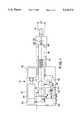
- FIG. 1is a schematic representation of the preferred electron beam source.
- FIG. 2(a)is a front view of the accelerator head mounted in a movable support.
- FIG. 2(b)is a side view of the accelerator head mounted in the movable support of FIG. 2(a).
- FIG. 3is a plan view of a layout of a hospital facility in which this invention may be used.
- a number of interrelated design elementsmust be considered when placing an IOEBT system in a surgical environment. These design elements include: (1) providing sufficient electron beam energy to meet penetration and dosage requirements; (2) minimizing the size and weight of the accelerator head; (3) providing means for mounting and moving the mechanical support for the accelerator head; and (4) providing adequate shielding for primary x-rays generated by the system as well as for scatter radiation.
- the preferred embodiment of this inventionmeets these requirements, in part, by using an X-band microwave accelerator as the electron beam source instead of a conventional S-band accelerator. Notwithstanding that use of an X-band accelerator in the preferred embodiment, it should be understood that this invention can be practiced with an S band accelerator like those commonly used in medical therapy systems. The disadvantage is the weight increase that users will be forced to contend with.
- the acceleratoragain preferably an X-band unit, and its applicator head are mounted on a mechanical support which serves to accurately place the accelerator head in proper position with minimum hazard to the patient and minimum time requirements for adjustments.
- the systemalso has a beam stopper to intercept primary photons generated either in the accelerator head or in the patient.
- the beam stopperis matched to the primary beam field size. Additional room shielding is provided as needed for the safety of the surgical team but generally not much shielding (not much more than that used during a catherization procedure) is required.
- the IOEBT system of this inventionmay be used in a dedicated room.
- a single modulatormay be used in to many surgical rooms and the accelerator head, its mechanical support and controls moved from room to room as needed. This will be further described in connection with FIG. 3.
- the preferred electron beam source for the IOEBT system of this inventionis an X-band linear accelerator operating at a peak beam energy of 13 MeV with settings at 6 MeV and 9 MeV.
- the electron beam sourcecomprises accelerator head 10 which includes an electron gun 12, a prebuncher 14, and a series of standing wave cavities 16 disposed along the centerline of housing 18.
- Electron gun 12is preferably a Litton M707.
- the injector cathode of electron gun 12operates at 40 kV and has a very small diameter emitting surface. This design provides low emittance and good capture efficiency while maintaining a low energy spread.
- the injectoralso has a non-interceptor grid to enable accurate control of the injected current. Injected current control makes it possible to (1) monitor the output beam signal and (2) to use a feedback circuit to regulate and adjust the injector current to stabilize the delivered dose.
- standing wave cavities 16vary in order to produce beam bunching, thus reducing energy spread.
- a solenoid or focusing coil 20is placed over the accelerating structure to confine the beam and to thereby optimize operation by improving transmission efficiency.
- a titanium window 44 at the beam outletmaintains a vacuum within the accelerator. Window 44 could also be formed from beryllium.
- a thin scattering foil 46 at the beam outletspreads the electrons. In the preferred embodiment, the electrons are scattered over a 20 cm ⁇ 20 cm treatment field with a maximum of 10% variation in dose rate.
- a removable treatment cone or application tube 19is disposed following scattering foil 46 at the beam exit region to define the treatment field size.
- a variety of applicator tubes of different sizesmay be used depending on the treatment desired.
- the microwave power necessary to drive the acceleratoris generated by a magnetron 30 such as the California Tube Laboratory model VMX 1100.
- magnetron 30is capable of operating at a peak power of 1.5 Megawatts and 1.5 kilowatts of average power, i.e., at a duty cycle of 0.001.
- the pulse length of the preferred magnetronis 4 microseconds, and the pulse repetition frequency can vary from 50 to 250 pulses per second.
- the systememploys a conventional modulator and power supply (not shown) using a hydrogen thyratron switching unit to produce 3 MW peak power for the magnetron via a suitable cable and cable connector.
- Power to magnetron 30is converted from 8-9 kV to 35 kV by a pulse transformer 32, also disposed within housing 18.
- Microwave power from the magnetronis transmitted to prebuncher 14 via a power splitter 36 and a phase shifter 38.
- the main poweris coupled to the standing wave cavities 16 via a four-port circulator 34. Power not absorbed in the accelerator is reflected and shunted into a water-cooled dummy load 39.
- the dummy loadis designed to absorb the complete power generated by the magnetron in the event of a load failure.
- a DeQuing regulation systemis used to maintain a constant pulse level.
- the resonant frequency of the magnetron and acceleratormust match in order to optimize system operation. This is achieved by using a tunable magnetron, with the tuner driven by a stepper motor 40.
- the stepper motoris controlled by an automatic frequency control system 42 which detects phase variation between the forward and reflected power applied to the accelerator, thus forming a tracking system to maintain optimum operation irrespective of temperature or load changes.
- a transmission chamber 48 at the beam outletmonitors dose rate and integral dose.
- the chamberis made from plastic elements (preferably Kapton) coated with a thin metallised layer to minimize production of bremsstrahlung x-rays.
- the accelerator head housing 10is mounted on a mechanical support or C-arm 50. As shown in FIGS. 2(a) and 2(b), the C-arm can articulate the electron beam source over a series of arcs. In the preferred embodiment, accelerator head housing 10 can rotate ⁇ 30° about the "X" and "Z" axes and has a vertical movement of 25 cm. Movement of the accelerator head is controlled by a joystick (not shown) having a proportional speed control.
- C-arm 50has a beam stopper 52 mounted on the side opposite accelerator head housing 10 to intercept the primary x-ray contaminants produced by the scattering foil and collimator.
- Beam stopper 52may be formed from lead, tungsten, or any other shielding material.
- the required size of the beam stopperdepends on the maximum field size of the electron beam. In the preferred embodiment, the electron beam field size is set at 15 cm ⁇ 15 cm. The preferred dimensions for a lead beam stopper are therefore approximately 40 cm ⁇ 40 cm with a thickness of approximately 20 cm.
- C-arm 50has a set of wheels 54.
- a set of support feet 56can be lowered to stabilize C-arm 50 or a braking mechanism set on wheels 54 when the unit is in its desired location.
- the IOEBT system of this inventionrequires a minimal amount of radiation shielding to be added to a preexisting surgical suite.
- a wall with a leaded glass windowmay separate the surgical team from the patient during operation of the IOEBT to protect the medical personnel from any stray radiation.
- the glass windowprovides visual monitoring of the patient which can supplement electronic video monitoring.
- the accelerator headmay be ceiling-mounted instead of mounted in the C-arm described above.
- the accelerator headmay be moved from room to room along tracks formed in the rooms' ceilings, or each accelerator head may be dedicated to a single room.
- FIG. 3illustrates two operating rooms 71 and 72 each with a patient table 73 and 74.
- a modulator and power source 75 and a water cooling system 76are positioned in the walls of the building and of the rooms and feeds to interfaces 77 and 78.
- the intraoperative device 80 of this inventionis shown in room 71 connected to room interface 77.
- a dotted illustrationis shown of the intraoperative device 80 in room 72 connected to interface 78. This is how the unit would appear when moved to room 72 for use in this operating theater.
- the electron beam sourcesmay be modified in accordance with techniques known in the art, such as by using lead cutouts to shape the electron beam distribution.
- the accelerator beam energymay be controlled by operating the system at a single output power level and using beryllium buttons to reduce the electron beam energy to the desired level.
Landscapes
- Health & Medical Sciences (AREA)
- Engineering & Computer Science (AREA)
- Biomedical Technology (AREA)
- Pathology (AREA)
- Nuclear Medicine, Radiotherapy & Molecular Imaging (AREA)
- Radiology & Medical Imaging (AREA)
- Life Sciences & Earth Sciences (AREA)
- Animal Behavior & Ethology (AREA)
- General Health & Medical Sciences (AREA)
- Public Health (AREA)
- Veterinary Medicine (AREA)
- Radiation-Therapy Devices (AREA)
Abstract
Description
Claims (15)
Priority Applications (1)
| Application Number | Priority Date | Filing Date | Title |
|---|---|---|---|
| US08/258,569US5418372A (en) | 1993-03-30 | 1994-06-10 | Intraoperative electron beam therapy system and facility |
Applications Claiming Priority (2)
| Application Number | Priority Date | Filing Date | Title |
|---|---|---|---|
| US08/040,115US5321271A (en) | 1993-03-30 | 1993-03-30 | Intraoperative electron beam therapy system and facility |
| US08/258,569US5418372A (en) | 1993-03-30 | 1994-06-10 | Intraoperative electron beam therapy system and facility |
Related Parent Applications (1)
| Application Number | Title | Priority Date | Filing Date |
|---|---|---|---|
| US08/040,115ContinuationUS5321271A (en) | 1993-03-30 | 1993-03-30 | Intraoperative electron beam therapy system and facility |
Publications (1)
| Publication Number | Publication Date |
|---|---|
| US5418372Atrue US5418372A (en) | 1995-05-23 |
Family
ID=21909197
Family Applications (2)
| Application Number | Title | Priority Date | Filing Date |
|---|---|---|---|
| US08/040,115Expired - LifetimeUS5321271A (en) | 1993-03-30 | 1993-03-30 | Intraoperative electron beam therapy system and facility |
| US08/258,569Expired - LifetimeUS5418372A (en) | 1993-03-30 | 1994-06-10 | Intraoperative electron beam therapy system and facility |
Family Applications Before (1)
| Application Number | Title | Priority Date | Filing Date |
|---|---|---|---|
| US08/040,115Expired - LifetimeUS5321271A (en) | 1993-03-30 | 1993-03-30 | Intraoperative electron beam therapy system and facility |
Country Status (7)
| Country | Link |
|---|---|
| US (2) | US5321271A (en) |
| EP (1) | EP0700578B1 (en) |
| JP (1) | JP2588480B2 (en) |
| AU (1) | AU6394994A (en) |
| DE (2) | DE69428698T2 (en) |
| RU (1) | RU2142827C1 (en) |
| WO (1) | WO1994023439A1 (en) |
Cited By (26)
| Publication number | Priority date | Publication date | Assignee | Title |
|---|---|---|---|---|
| US6465957B1 (en) | 2001-05-25 | 2002-10-15 | Siemens Medical Solutions Usa, Inc. | Standing wave linear accelerator with integral prebunching section |
| US20050078794A1 (en)* | 2003-09-12 | 2005-04-14 | Leek Paul H. | Multiple energy x-ray source and inspection apparatus employing same |
| US20070112392A1 (en)* | 2005-11-15 | 2007-05-17 | Alon Konchitsky | Microwave energy head therapy |
| US20100034355A1 (en)* | 2008-08-11 | 2010-02-11 | Langeveld Willem G J | Systems and Methods for Using An Intensity-Modulated X-Ray Source |
| US20100066256A1 (en)* | 2008-09-16 | 2010-03-18 | Varian Medical Systems, Inc. | Device for Reducing Peak Field an Accelerator System |
| US20100098214A1 (en)* | 2008-10-22 | 2010-04-22 | Varian Medical Systems, Inc. | Methods and Systems for Treating Breast Cancer Using External Beam Radiation |
| US20110017920A1 (en)* | 2009-07-22 | 2011-01-27 | Intraop Medical Corporation | Method and system for electron beam applications |
| US20120025106A1 (en)* | 2009-04-14 | 2012-02-02 | Manfred Apel | Beam head |
| US8837670B2 (en) | 2006-05-05 | 2014-09-16 | Rapiscan Systems, Inc. | Cargo inspection system |
| US9052264B2 (en) | 2010-02-03 | 2015-06-09 | Rapiscan Systems, Inc. | Scanning systems |
| US9052403B2 (en) | 2002-07-23 | 2015-06-09 | Rapiscan Systems, Inc. | Compact mobile cargo scanning system |
| US9218933B2 (en) | 2011-06-09 | 2015-12-22 | Rapidscan Systems, Inc. | Low-dose radiographic imaging system |
| US9223050B2 (en) | 2005-04-15 | 2015-12-29 | Rapiscan Systems, Inc. | X-ray imaging system having improved mobility |
| US9223049B2 (en) | 2002-07-23 | 2015-12-29 | Rapiscan Systems, Inc. | Cargo scanning system with boom structure |
| US9224573B2 (en) | 2011-06-09 | 2015-12-29 | Rapiscan Systems, Inc. | System and method for X-ray source weight reduction |
| US9274065B2 (en) | 2012-02-08 | 2016-03-01 | Rapiscan Systems, Inc. | High-speed security inspection system |
| US9285498B2 (en) | 2003-06-20 | 2016-03-15 | Rapiscan Systems, Inc. | Relocatable X-ray imaging system and method for inspecting commercial vehicles and cargo containers |
| US9332624B2 (en) | 2008-05-20 | 2016-05-03 | Rapiscan Systems, Inc. | Gantry scanner systems |
| US9393439B2 (en) | 2010-03-01 | 2016-07-19 | Intraop Medical Corporation | Radiotherapy combined with hypoxic cell sensitizers |
| US9435752B2 (en) | 2010-02-03 | 2016-09-06 | Rapiscan Systems, Inc. | Systems and methods for scanning objects |
| WO2017151763A1 (en) | 2016-03-01 | 2017-09-08 | Intraop Medical Corporation | Low energy electron beam radiation system that generates electron beams with precisely controlled and adjustable penetration depth useful for therapeutic applications |
| US9791590B2 (en) | 2013-01-31 | 2017-10-17 | Rapiscan Systems, Inc. | Portable security inspection system |
| US10754057B2 (en) | 2016-07-14 | 2020-08-25 | Rapiscan Systems, Inc. | Systems and methods for improving penetration of radiographic scanners |
| US11135449B2 (en) | 2017-05-04 | 2021-10-05 | Intraop Medical Corporation | Machine vision alignment and positioning system for electron beam treatment systems |
| US12387900B2 (en) | 2022-02-03 | 2025-08-12 | Rapiscan Holdings, Inc. | Systems and methods for real-time energy and dose monitoring of an X-ray linear accelerator |
| US12420116B2 (en) | 2019-09-14 | 2025-09-23 | Intraop Medical Corporation | Methods and systems for using and controlling higher dose rate ionizing radiation in short time intervals |
Families Citing this family (34)
| Publication number | Priority date | Publication date | Assignee | Title |
|---|---|---|---|---|
| US5321271A (en)* | 1993-03-30 | 1994-06-14 | Intraop, Inc. | Intraoperative electron beam therapy system and facility |
| IT1281184B1 (en)* | 1994-09-19 | 1998-02-17 | Giorgio Trozzi Amministratore | EQUIPMENT FOR INTRAOPERATIVE RADIOTHERAPY BY MEANS OF LINEAR ACCELERATORS THAT CAN BE USED DIRECTLY IN THE OPERATING ROOM |
| US5661377A (en)* | 1995-02-17 | 1997-08-26 | Intraop Medical, Inc. | Microwave power control apparatus for linear accelerator using hybrid junctions |
| US6078036A (en)* | 1998-05-06 | 2000-06-20 | Intraop Medical, Inc. | Laser soft docking system for medical treatment system |
| JP2000167029A (en)* | 1998-12-01 | 2000-06-20 | Mitsubishi Electric Corp | Radiation irradiation device |
| DE10041473B9 (en)* | 2000-08-24 | 2004-10-14 | Müller, Reinhold G., Prof.Dr. | Device for irradiating tissue |
| US7183563B2 (en)* | 2000-12-13 | 2007-02-27 | Advanced Electron Beams, Inc. | Irradiation apparatus |
| EP1224953A1 (en)* | 2001-01-18 | 2002-07-24 | HITESYS S.p.A. | Apparatus for the linear acceleration of electrons, particulary for intraoperative radiation therapy |
| WO2003018131A1 (en)* | 2001-08-24 | 2003-03-06 | Mitsubishi Heavy Industries, Ltd. | Radiological treatment apparatus |
| JPWO2003018132A1 (en)* | 2001-08-24 | 2004-12-09 | 三菱重工業株式会社 | Radiotherapy equipment |
| ATE343414T1 (en)* | 2001-12-06 | 2006-11-15 | Hitesys Spa | DEVICE FOR ELECTRON LINEAR ACCELERATION DURING INTRA-OPERATIVE RADIATION THERAPY |
| IT1333559B (en)* | 2002-05-31 | 2006-05-04 | Info & Tech Spa | INTRAOPERATIVE RADIOTHERAPY MACHINE. |
| US7312461B2 (en)* | 2004-09-21 | 2007-12-25 | Uchicago Argonne Llc | Laparoscopic tumor therapy using high energy electron irradiation |
| DE102004062473B4 (en)* | 2004-09-30 | 2006-11-30 | Siemens Ag | Medical radiation therapy arrangement |
| RU2288753C2 (en)* | 2005-01-27 | 2006-12-10 | Анатолий Васильевич Кобзев | Device for making physiotherapeutic effect |
| ITVE20050037A1 (en)* | 2005-08-04 | 2007-02-05 | Marco Sumini | EQUIPMENT FOR RADIOTHERAPY OF INTERSTIAL AND INTRAOPERATIVE RADIOTHERAPY. |
| US20080043910A1 (en)* | 2006-08-15 | 2008-02-21 | Tomotherapy Incorporated | Method and apparatus for stabilizing an energy source in a radiation delivery device |
| DE102007042340C5 (en)* | 2007-09-06 | 2011-09-22 | Mt Mechatronics Gmbh | Particle therapy system with moveable C-arm |
| DK2197547T3 (en)* | 2007-09-13 | 2014-07-07 | Toby D Henderson | IMAGING POSITIONING SYSTEM AND HAVING ROBOT LOCATED D-ARM |
| EP2190530B1 (en)* | 2007-09-13 | 2017-11-08 | Toby D. Henderson | Patient positioner system |
| US8111025B2 (en)* | 2007-10-12 | 2012-02-07 | Varian Medical Systems, Inc. | Charged particle accelerators, radiation sources, systems, and methods |
| ES2332682B1 (en)* | 2007-10-17 | 2011-01-17 | Universitat Politecnica De Catalunya | MOBILE INTRAOPERATIVE RADIOTHERAPY SYSTEM BY ELECTRONIC BEAM. |
| US8394007B2 (en) | 2008-10-31 | 2013-03-12 | Toby D Henderson | Inclined beamline motion mechanism |
| EP2962309B1 (en) | 2013-02-26 | 2022-02-16 | Accuray, Inc. | Electromagnetically actuated multi-leaf collimator |
| US9126036B2 (en)* | 2013-03-15 | 2015-09-08 | Paul H. Leek | Optionally transportable machine for use in intraoperative electron radiation therapy |
| GB2528863B (en)* | 2014-07-31 | 2016-07-13 | Elekta ltd | Radiotherapy systems and methods |
| CN107158581B (en) | 2017-05-15 | 2019-11-22 | 中国医学科学院肿瘤医院 | Intraoperative radiotherapy scanning path planning method and intraoperative radiotherapy system |
| CN107174753B (en) | 2017-05-15 | 2019-09-03 | 中国医学科学院肿瘤医院 | Multi-arm Intraoperative Radiation Therapy Device |
| CN109395258A (en)* | 2017-08-18 | 2019-03-01 | 盖炜 | Precise radiotherapy method and system based on sorghum procyanidins |
| GB2567672B (en) | 2017-10-20 | 2020-09-02 | Muir Ip Ltd | Radiation therapy system |
| CN108392741B (en)* | 2018-04-04 | 2024-03-29 | 西安大医集团股份有限公司 | Microwave power control device and radiotherapy equipment |
| US11524181B2 (en) | 2018-04-17 | 2022-12-13 | Best Theratronics Ltd. | Intraoperative radiation therapy system |
| GB2583140B (en) | 2019-04-18 | 2023-08-30 | Muir Ip Ltd | Radiation therapy system |
| IT201900016760A1 (en) | 2019-09-19 | 2021-03-19 | S I T Sordina Iort Tech S P A | DEVICE FOR THE RADIOTHERAPY TREATMENT OF CANCER PATIENTS |
Citations (1)
| Publication number | Priority date | Publication date | Assignee | Title |
|---|---|---|---|---|
| US5321271A (en)* | 1993-03-30 | 1994-06-14 | Intraop, Inc. | Intraoperative electron beam therapy system and facility |
Family Cites Families (12)
| Publication number | Priority date | Publication date | Assignee | Title |
|---|---|---|---|---|
| US2781454A (en)* | 1952-12-04 | 1957-02-12 | Ca Atomic Energy Ltd | Rotational therapy unit |
| SU541311A1 (en)* | 1975-11-05 | 1978-11-15 | Aleksashin L V | Device for controlling radiotherapy rotary apparatus |
| CA1045717A (en)* | 1977-05-09 | 1979-01-02 | Majesty (Her) In Right Of Canada As Represented By Atomic Energy Of Cana Da Limited | Standing wave accelerator structure with on-axis couplers |
| US4638814A (en)* | 1984-09-11 | 1987-01-27 | Siemens Medical Laboratories | Electron accelerator unit for electron beam therapy |
| US5161546A (en)* | 1986-09-24 | 1992-11-10 | Bronn Donald G | System for intraoperative electron beam radiotherapy using remotely located beam generator |
| US4947842A (en)* | 1988-09-22 | 1990-08-14 | Medical Engineering And Development Institute, Inc. | Method and apparatus for treating tissue with first and second modalities |
| EP0371303B1 (en)* | 1988-11-29 | 1994-04-27 | Varian International AG. | Radiation therapy apparatus |
| US5008907A (en)* | 1989-05-31 | 1991-04-16 | The Regents Of The University Of California | Therapy x-ray scanner |
| US5037374A (en)* | 1989-11-29 | 1991-08-06 | Carol Mark P | Stereotactic-guided radiation therapy system with variable-length compensating collimator |
| US5044006A (en)* | 1990-04-27 | 1991-08-27 | Cyrulnik Reuven A | Microwave frequency modulation of x-ray beam for radio therapy treatment system |
| US5153900A (en)* | 1990-09-05 | 1992-10-06 | Photoelectron Corporation | Miniaturized low power x-ray source |
| JPH0779813B2 (en)* | 1992-03-24 | 1995-08-30 | 潤 池辺 | Radiation therapy equipment |
- 1993
- 1993-03-30USUS08/040,115patent/US5321271A/ennot_activeExpired - Lifetime
- 1994
- 1994-02-22JPJP6522065Apatent/JP2588480B2/ennot_activeExpired - Fee Related
- 1994-02-22DEDE69428698Tpatent/DE69428698T2/ennot_activeExpired - Lifetime
- 1994-02-22EPEP94911427Apatent/EP0700578B1/ennot_activeExpired - Lifetime
- 1994-02-22RURU95121733Apatent/RU2142827C1/ennot_activeIP Right Cessation
- 1994-02-22WOPCT/US1994/002144patent/WO1994023439A1/enactiveIP Right Grant
- 1994-02-22AUAU63949/94Apatent/AU6394994A/ennot_activeAbandoned
- 1994-02-22DEDE69428698.2Apatent/DE69428698C9/ennot_activeExpired - Lifetime
- 1994-06-10USUS08/258,569patent/US5418372A/ennot_activeExpired - Lifetime
Patent Citations (1)
| Publication number | Priority date | Publication date | Assignee | Title |
|---|---|---|---|---|
| US5321271A (en)* | 1993-03-30 | 1994-06-14 | Intraop, Inc. | Intraoperative electron beam therapy system and facility |
Cited By (51)
| Publication number | Priority date | Publication date | Assignee | Title |
|---|---|---|---|---|
| US6465957B1 (en) | 2001-05-25 | 2002-10-15 | Siemens Medical Solutions Usa, Inc. | Standing wave linear accelerator with integral prebunching section |
| US10007019B2 (en) | 2002-07-23 | 2018-06-26 | Rapiscan Systems, Inc. | Compact mobile cargo scanning system |
| US9052403B2 (en) | 2002-07-23 | 2015-06-09 | Rapiscan Systems, Inc. | Compact mobile cargo scanning system |
| US10670769B2 (en) | 2002-07-23 | 2020-06-02 | Rapiscan Systems, Inc. | Compact mobile cargo scanning system |
| US9223049B2 (en) | 2002-07-23 | 2015-12-29 | Rapiscan Systems, Inc. | Cargo scanning system with boom structure |
| US9285498B2 (en) | 2003-06-20 | 2016-03-15 | Rapiscan Systems, Inc. | Relocatable X-ray imaging system and method for inspecting commercial vehicles and cargo containers |
| US7110500B2 (en) | 2003-09-12 | 2006-09-19 | Leek Paul H | Multiple energy x-ray source and inspection apparatus employing same |
| US20050078794A1 (en)* | 2003-09-12 | 2005-04-14 | Leek Paul H. | Multiple energy x-ray source and inspection apparatus employing same |
| US9223050B2 (en) | 2005-04-15 | 2015-12-29 | Rapiscan Systems, Inc. | X-ray imaging system having improved mobility |
| US7548779B2 (en) | 2005-11-15 | 2009-06-16 | Alon Konchitsky | Microwave energy head therapy |
| US20070112392A1 (en)* | 2005-11-15 | 2007-05-17 | Alon Konchitsky | Microwave energy head therapy |
| US8837670B2 (en) | 2006-05-05 | 2014-09-16 | Rapiscan Systems, Inc. | Cargo inspection system |
| US9279901B2 (en) | 2006-05-05 | 2016-03-08 | Rapiscan Systems, Inc. | Cargo inspection system |
| US10098214B2 (en) | 2008-05-20 | 2018-10-09 | Rapiscan Systems, Inc. | Detector support structures for gantry scanner systems |
| US9332624B2 (en) | 2008-05-20 | 2016-05-03 | Rapiscan Systems, Inc. | Gantry scanner systems |
| US8437448B2 (en) | 2008-08-11 | 2013-05-07 | Rapiscan Systems, Inc. | Systems and methods for using an intensity-modulated X-ray source |
| US8781067B2 (en) | 2008-08-11 | 2014-07-15 | Rapiscan Systems, Inc. | Systems and methods for using an intensity-modulated X-ray source |
| US20100034355A1 (en)* | 2008-08-11 | 2010-02-11 | Langeveld Willem G J | Systems and Methods for Using An Intensity-Modulated X-Ray Source |
| US8054937B2 (en) | 2008-08-11 | 2011-11-08 | Rapiscan Systems, Inc. | Systems and methods for using an intensity-modulated X-ray source |
| US8330397B2 (en)* | 2008-09-16 | 2012-12-11 | Varian Medical Systems, Inc. | Device for reducing peak field an accelerator system |
| US20100066256A1 (en)* | 2008-09-16 | 2010-03-18 | Varian Medical Systems, Inc. | Device for Reducing Peak Field an Accelerator System |
| US7940891B2 (en)* | 2008-10-22 | 2011-05-10 | Varian Medical Systems, Inc. | Methods and systems for treating breast cancer using external beam radiation |
| US20100098214A1 (en)* | 2008-10-22 | 2010-04-22 | Varian Medical Systems, Inc. | Methods and Systems for Treating Breast Cancer Using External Beam Radiation |
| US20120025106A1 (en)* | 2009-04-14 | 2012-02-02 | Manfred Apel | Beam head |
| US8946657B2 (en)* | 2009-04-14 | 2015-02-03 | Siemens Aktiengesellschaft | Beam head |
| US8269197B2 (en) | 2009-07-22 | 2012-09-18 | Intraop Medical Corporation | Method and system for electron beam applications |
| US20110017920A1 (en)* | 2009-07-22 | 2011-01-27 | Intraop Medical Corporation | Method and system for electron beam applications |
| US9052264B2 (en) | 2010-02-03 | 2015-06-09 | Rapiscan Systems, Inc. | Scanning systems |
| US9435752B2 (en) | 2010-02-03 | 2016-09-06 | Rapiscan Systems, Inc. | Systems and methods for scanning objects |
| US9393439B2 (en) | 2010-03-01 | 2016-07-19 | Intraop Medical Corporation | Radiotherapy combined with hypoxic cell sensitizers |
| US9656098B2 (en) | 2010-03-01 | 2017-05-23 | Intraop Medical Corporation | Radiotherapy combined with hypoxic cell sensitizers |
| US9224573B2 (en) | 2011-06-09 | 2015-12-29 | Rapiscan Systems, Inc. | System and method for X-ray source weight reduction |
| US9218933B2 (en) | 2011-06-09 | 2015-12-22 | Rapidscan Systems, Inc. | Low-dose radiographic imaging system |
| US12169264B2 (en) | 2012-02-08 | 2024-12-17 | Rapiscan Systems, Inc. | High-speed security inspection system |
| US9274065B2 (en) | 2012-02-08 | 2016-03-01 | Rapiscan Systems, Inc. | High-speed security inspection system |
| US11852775B2 (en) | 2012-02-08 | 2023-12-26 | Rapiscan Systems, Inc. | High-speed security inspection system |
| US10698128B2 (en) | 2012-02-08 | 2020-06-30 | Rapiscan Systems, Inc. | High-speed security inspection system |
| US11561321B2 (en) | 2012-02-08 | 2023-01-24 | Rapiscan Systems, Inc. | High-speed security inspection system |
| US11119245B2 (en) | 2012-02-08 | 2021-09-14 | Rapiscan Systems, Inc. | High-speed security inspection system |
| US11550077B2 (en) | 2013-01-31 | 2023-01-10 | Rapiscan Systems, Inc. | Portable vehicle inspection portal with accompanying workstation |
| US10317566B2 (en) | 2013-01-31 | 2019-06-11 | Rapiscan Systems, Inc. | Portable security inspection system |
| US9791590B2 (en) | 2013-01-31 | 2017-10-17 | Rapiscan Systems, Inc. | Portable security inspection system |
| EP3838344A1 (en) | 2016-03-01 | 2021-06-23 | Intraop Medical Corporation | Electron beam radiation system useful for therapeutic applications |
| US11285341B2 (en) | 2016-03-01 | 2022-03-29 | Intraop Medical Corporation | Low energy electron beam radiation system that generates electron beams with precisely controlled and adjustable penetration depth useful for therapeutic applications |
| US10485993B2 (en) | 2016-03-01 | 2019-11-26 | Intraop Medical Corporation | Low energy electron beam radiation system that generates electron beams with precisely controlled and adjustable penetration depth useful for therapeutic applications |
| WO2017151763A1 (en) | 2016-03-01 | 2017-09-08 | Intraop Medical Corporation | Low energy electron beam radiation system that generates electron beams with precisely controlled and adjustable penetration depth useful for therapeutic applications |
| US11397276B2 (en) | 2016-07-14 | 2022-07-26 | Rapiscan Systems, Inc. | Systems and methods for improving penetration of radiographic scanners |
| US10754057B2 (en) | 2016-07-14 | 2020-08-25 | Rapiscan Systems, Inc. | Systems and methods for improving penetration of radiographic scanners |
| US11135449B2 (en) | 2017-05-04 | 2021-10-05 | Intraop Medical Corporation | Machine vision alignment and positioning system for electron beam treatment systems |
| US12420116B2 (en) | 2019-09-14 | 2025-09-23 | Intraop Medical Corporation | Methods and systems for using and controlling higher dose rate ionizing radiation in short time intervals |
| US12387900B2 (en) | 2022-02-03 | 2025-08-12 | Rapiscan Holdings, Inc. | Systems and methods for real-time energy and dose monitoring of an X-ray linear accelerator |
Also Published As
| Publication number | Publication date |
|---|---|
| EP0700578A1 (en) | 1996-03-13 |
| JP2588480B2 (en) | 1997-03-05 |
| AU6394994A (en) | 1994-10-24 |
| WO1994023439A1 (en) | 1994-10-13 |
| US5321271A (en) | 1994-06-14 |
| DE69428698D1 (en) | 2001-11-22 |
| DE69428698C9 (en) | 2014-06-18 |
| DE69428698C5 (en) | 2013-04-04 |
| EP0700578A4 (en) | 1997-01-15 |
| EP0700578B1 (en) | 2001-10-17 |
| RU2142827C1 (en) | 1999-12-20 |
| DE69428698T2 (en) | 2002-07-11 |
| JPH07507479A (en) | 1995-08-24 |
Similar Documents
| Publication | Publication Date | Title |
|---|---|---|
| US5418372A (en) | Intraoperative electron beam therapy system and facility | |
| CN102473470B (en) | For the method and system of electron beam applications | |
| US11285341B2 (en) | Low energy electron beam radiation system that generates electron beams with precisely controlled and adjustable penetration depth useful for therapeutic applications | |
| US6445766B1 (en) | System and method for improved diagnostic imaging in a radiation treatment system | |
| US9126036B2 (en) | Optionally transportable machine for use in intraoperative electron radiation therapy | |
| US5161546A (en) | System for intraoperative electron beam radiotherapy using remotely located beam generator | |
| Kamino et al. | Development of an ultrasmall‐band linear accelerator guide for a four‐dimensional image‐guided radiotherapy system with a gimbaled x‐ray head | |
| CN114845773A (en) | Method and system for using and controlling higher dose rate ionizing radiation in short time intervals | |
| CN109464749B (en) | Neutron capture therapy system | |
| Kutsaev et al. | Compact X-Band electron linac for radiotherapy and security applications | |
| Meurk et al. | The Mobetron: a new concept for IORT | |
| CN109464752B (en) | Neutron capture therapy system | |
| Haimson et al. | A new design 6 MeV linear accelerator system for supervoltage radiotherapy | |
| Meurk et al. | The development of a small, economic mobile unit for intraoperative electron beam therapy | |
| Yoshida et al. | Electron accelerator and beam irradiation system | |
| Tanabe et al. | Medical applications of C-band accelerator technologies | |
| US20230256267A1 (en) | 70 mev to 150 mev cyclotron dedicated for medical treatment including a robotic chair/table | |
| Konrad | Siemens Medical Laboratories, Inc., Concord, CA 94520 | |
| Richman et al. | Therapfutic and Research Applications of a 40 MeV Electron Linear Accelerator | |
| Schonberg et al. | New medical linacs | |
| Minnaar | The first two electron linear accelerators in South Africa |
Legal Events
| Date | Code | Title | Description |
|---|---|---|---|
| STCF | Information on status: patent grant | Free format text:PATENTED CASE | |
| AS | Assignment | Owner name:INTRAOP MEDICAL, INC., CALIFORNIA Free format text:CHANGE OF NAME;ASSIGNOR:INTRAOP, INC.;REEL/FRAME:008412/0116 Effective date:19961120 | |
| FPAY | Fee payment | Year of fee payment:4 | |
| AS | Assignment | Owner name:PACIFIC REPUBLIC CAPITAL CORP, CALIFORNIA Free format text:ASSIGNMENT OF ASSIGNORS INTEREST;ASSIGNOR:INTRAOP MEDICAL, INC.;REEL/FRAME:009833/0336 Effective date:19990310 | |
| AS | Assignment | Owner name:SILICON VALLEY BANK, CALIFORNIA Free format text:SECURITY AGREEMENT;ASSIGNOR:INTRAOP MEDICAL, INC.;REEL/FRAME:012631/0124 Effective date:20010705 | |
| FPAY | Fee payment | Year of fee payment:8 | |
| AS | Assignment | Owner name:INTRAOP MEDICAL, INC., CALIFORNIA Free format text:RELEASE BY SECURED PARTY;ASSIGNOR:SILICON VALLEY BANK;REEL/FRAME:013699/0843 Effective date:20030123 | |
| AS | Assignment | Owner name:ABS SOS-PLUS PARTNERS LTD., FLORIDA Free format text:SECURITY AGREEMENT;ASSIGNOR:INTRAOP MEDICAL CORPORATION;REEL/FRAME:016536/0775 Effective date:20050831 Owner name:REGENMACHER HOLDINGS LTD., FLORIDA Free format text:SECURITY AGREEMENT;ASSIGNOR:INTRAOP MEDICAL CORPORATION;REEL/FRAME:016536/0775 Effective date:20050831 | |
| FPAY | Fee payment | Year of fee payment:12 | |
| AS | Assignment | Owner name:LACUNA VENTURE FUND LLLP, AS AGENT, COLORADO Free format text:INTELLECTUAL PROPERTY SECURITY AGREEMENT;ASSIGNOR:INTRAOP MEDICAL CORPORATION;REEL/FRAME:021838/0162 Effective date:20080930 | |
| CC | Certificate of correction |