US5417866A - Continuous flow polymer filtration apparatus and process - Google Patents
Continuous flow polymer filtration apparatus and processDownload PDFInfo
- Publication number
- US5417866A US5417866AUS08/087,215US8721593AUS5417866AUS 5417866 AUS5417866 AUS 5417866AUS 8721593 AUS8721593 AUS 8721593AUS 5417866 AUS5417866 AUS 5417866A
- Authority
- US
- United States
- Prior art keywords
- filter
- bore
- slide member
- filter assembly
- assemblies
- Prior art date
- Legal status (The legal status is an assumption and is not a legal conclusion. Google has not performed a legal analysis and makes no representation as to the accuracy of the status listed.)
- Expired - Lifetime
Links
- 229920000642polymerPolymers0.000titleclaimsabstractdescription78
- 238000001914filtrationMethods0.000titleclaimsabstractdescription26
- 238000000034methodMethods0.000titleclaimsdescription21
- 230000008569processEffects0.000titledescription5
- 230000000712assemblyEffects0.000claimsabstractdescription88
- 238000000429assemblyMethods0.000claimsabstractdescription88
- 238000007789sealingMethods0.000claimsabstractdescription72
- 239000012530fluidSubstances0.000claimsabstractdescription22
- 238000004891communicationMethods0.000claimsdescription13
- 239000012535impuritySubstances0.000description10
- 125000006850spacer groupChemical group0.000description9
- 238000011144upstream manufacturingMethods0.000description9
- 230000008859changeEffects0.000description8
- 230000009977dual effectEffects0.000description5
- 230000007423decreaseEffects0.000description2
- 238000001125extrusionMethods0.000description2
- 230000007704transitionEffects0.000description2
- 238000001816coolingMethods0.000description1
- 230000008878couplingEffects0.000description1
- 238000010168coupling processMethods0.000description1
- 238000005859coupling reactionMethods0.000description1
- 230000000881depressing effectEffects0.000description1
- 230000003670easy-to-cleanEffects0.000description1
- 238000010438heat treatmentMethods0.000description1
- 230000013011matingEffects0.000description1
- 239000002184metalSubstances0.000description1
- 239000008188pelletSubstances0.000description1
- 238000013022ventingMethods0.000description1
- 230000000007visual effectEffects0.000description1
Images


Classifications
- B—PERFORMING OPERATIONS; TRANSPORTING
- B29—WORKING OF PLASTICS; WORKING OF SUBSTANCES IN A PLASTIC STATE IN GENERAL
- B29C—SHAPING OR JOINING OF PLASTICS; SHAPING OF MATERIAL IN A PLASTIC STATE, NOT OTHERWISE PROVIDED FOR; AFTER-TREATMENT OF THE SHAPED PRODUCTS, e.g. REPAIRING
- B29C48/00—Extrusion moulding, i.e. expressing the moulding material through a die or nozzle which imparts the desired form; Apparatus therefor
- B29C48/25—Component parts, details or accessories; Auxiliary operations
- B29C48/36—Means for plasticising or homogenising the moulding material or forcing it through the nozzle or die
- B29C48/50—Details of extruders
- B29C48/69—Filters or screens for the moulding material
- B29C48/691—Arrangements for replacing filters, e.g. with two parallel filters for alternate use
- B29C48/6912—Arrangements for replacing filters, e.g. with two parallel filters for alternate use the filters being fitted on a single rectilinearly reciprocating slide
- B—PERFORMING OPERATIONS; TRANSPORTING
- B29—WORKING OF PLASTICS; WORKING OF SUBSTANCES IN A PLASTIC STATE IN GENERAL
- B29C—SHAPING OR JOINING OF PLASTICS; SHAPING OF MATERIAL IN A PLASTIC STATE, NOT OTHERWISE PROVIDED FOR; AFTER-TREATMENT OF THE SHAPED PRODUCTS, e.g. REPAIRING
- B29C48/00—Extrusion moulding, i.e. expressing the moulding material through a die or nozzle which imparts the desired form; Apparatus therefor
- B29C48/03—Extrusion moulding, i.e. expressing the moulding material through a die or nozzle which imparts the desired form; Apparatus therefor characterised by the shape of the extruded material at extrusion
Definitions
- plastic extrudersIn an extrusion process, polymer pellets are heated and melted as they are driven through a barrel by an extrusion screw.
- Plastic extrudersgenerally require the filtration of impurities from the molten polymer exiting the extruder screw with a filter such as a screen in order to produce a high quality product. Once the filter has become dirty by trapping a certain amount of impurities, it is more difficult for the polymer to pass through the filter. As a result, the pressure of the polymer upstream from the filter increases and output decreases.
- a well-known type of screen changerconsists of a hydraulically operated slide in which two filter assemblies are located. One filter assembly is positioned on-line within the bore of the extruder to filter polymer while the other filter assembly is off-line external to the bore. In order to replace the dirty on-line filter with the clean off-line filter, the slide is shifted, thereby moving the clean filter on-line with the bore and moving the dirty filter off-line for replacement.
- a problem with conventional hydraulic screen changersis that there is a momentary leakage of polymer resulting in loss of pressure and flow while the slide is being shifted.
- a solution to the flow and pressure interruptionwas proposed to allow for continuous flow operation with filter changing. That solution provided an array of filter modules adapted to slide through the extruder barrel, with only one filter positioned in the bore at a time. To allow for proper sealing during filter changes, a wide sealing region was provided to either side of the bore. A clean filter would shift into one sealing region as a clean filter shifted into the bore, a dirty filter shifted into the other sealing region, and yet another dirty filter shifted out of the barrel. The latter filter module would be removed, the filter could be changed and the module would be replaced at the clean filter side of the barrel. The need for manual handling of the filter modules proved cumbersome and undesirable.
- a second solutionuses a screen changer having dual bores and two sliding filters.
- polymerflows through both bores and passes through both filters.
- the filtersbecome dirty, the filters are changed one bore at a time.
- a slidemoves the dirty filter through a seal region to a location outside of the extruder barrel for changing.
- the polymercan flow through the one bore and remain continuous while the other bore is closed off by the slide.
- a problem with the dual bore screen changeris that when the filters are dirty and one filter is being replaced, all of the polymer flow must flow through a single dirty filter. As a result, there is an increased resistance to polymer flow evidenced by a high pressure spike during filter changes. Furthermore, the need for dual bores requires lengths of flow lines to split the single bore exiting the extruder screw into two flow paths and combine them back together, resulting in a long flow path. As a result, the dual bore continuous flow changer is a rather bulky piece of machinery. The long flow path through the dual bore changer requires a larger inventory of polymer than single bore screen changers, and when one bore is closed off during a filter change, a stagnant branch of polymer is produced.
- the present inventionprovides a continuous flow filter changing apparatus and method including a housing and a bore having a width extending through the housing.
- the boredefines a fluid path through which polymer is capable of flowing continuously.
- a reciprocating slide membermoves within and is in sealing contact with a slide channel which extends through the housing of the filter changer transverse to the bore.
- the slide channelhas a sealing region adjacent to the bore and extending a width between the bore and the exterior of the housing.
- the slide memberintersects the fluid flow path of the bore and houses first and second filter assemblies which are proximate to each other.
- the slide memberis capable of positioning either one of the first and second filter assemblies to be aligned with the bore during normal operation while the other of the first and second filter assemblies is off-line such that it is not in fluid communication with the bore.
- Each filter assemblycomprises at least one filter element which has a width that is less than the width of the sealing region such that there is no fluid leakage path along the slide channel in communication between the bore and the exterior of the housing at any position of the slide member. This allows each filter assembly to be moved without objectionable polymer leakage to a position exterior of the sealing region such that the filter elements may be replaced.
- the filter assembliesare proximately located in the slide member such that the distance between adjacent filter assemblies is less than the width of the bore. This ensures that the slide member does not completely obstruct the bore and that at least a portion of one filter assembly is in fluid communication with the bore at any position of the slide member such that there is continuous flow of filtered polymer through the bore.
- the moveable memberis also adapted to position either of the first and second filter assemblies external to the housing to expose the filters for replacement while the other of the first and second filter assemblies is on-line such that it is in fluid communication with the bore both upstream and downstream of the other of the first and second filter assemblies.
- the distance between the first and second filter assembliesis less than the width of the sealing region such that when the slide member moves the other of the first and second filter assemblies to be exposed beyond the sealing region, the one filter assembly is partially misaligned with the bore. Additionally, passageways in fluid communication with the bore allow filter assemblies which are positioned off-line to be pre-filled with polymer and purged of air before moved on-line.
- each filter assemblyis made up of a single filter.
- each filter assemblyincludes two or more filter elements which are proximate to each other. The plural filter elements of an assembly operate as a single filter in operation but permit shorter sealing regions for a more compact system.
- the continuous flow filter changing apparatusprovides a compact and simple apparatus and method for changing filters in an extruder without interrupting flow or causing excessive flow resistance. Additionally, the filter changer has a short, single bore and, therefore, a large inventory of polymer does not reside in the bore of the filter changer. Furthermore, there are no devious flow paths within the bore and as a result, stagnant flows of polymer do not form.
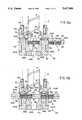
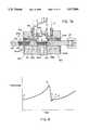
- FIG. 1is a front view of a continuous flow filter changer embodying the present invention.
- FIG. 2is a top partial sectional view of the continuous flow filter changer of FIG. 1.
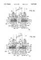
- FIGS. 3a-3eare top sectional views of the bore and slide region of the filter changer of FIGS. 1 and 2 depicting various steps in the sequence of operation of the slide member.
- FIG. 4is a graph depicting the relative pressure versus time for the sequence of FIGS. 3a-3e.
- FIGS. 5a and 5bare top sectional views of the bore and slide region of a preferred filter changer depicting two steps in the sequence of operation of the slide member.
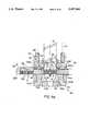
- FIGS. 6a-6eare top sectional views of the bore and slide region of another preferred filter changer depicting various steps in the sequence of operation of the slide member.
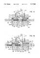
- FIGS. 7a-7eare top sectional views of the bore and slide region of yet another preferred filter changer depicting various steps in the sequence of operation of the slide member.
- FIG. 8is a graph depicting the relative pressure versus time for the sequence of FIGS. 7a-7e.
- filter changer 10includes a housing 80 having a tapering bore 36 which is affixed to an extruder 12 proximate to the extruder screw 14. Slidably attached within housing 80 is a slide member 26.
- Slide member 26houses two filter assemblies A and B which are respectively split into two rectangular filtering regions A1, A2 and B1, B2, respectively, for filtering polymer which exits extruder 12.
- Each filtering regioncontains a rectangular breaker plate 68 positioned on a step, there being a number of holes formed within the plate, and a replaceable filter element 66.
- the surfaces of slide member 26 which border the filtering regionsprovide closed sealing surfaces for the filtering regions.
- the breaker plates 68 and filter elements 66can be of other suitable shapes.
- Slide member 26is connected by a coupling member 24 to a hydraulic cylinder 16 which actuates the motion of slide member 26.
- hydraulic cylinder 16moves slide member 26 to position either filter assembly A or B in alignment with bore 36 in order to filter impurities from polymer flowing through bore 36. In such a position, the filter assembly extends substantially across bore 36.
- slide member 26is moved to position a clean filter assembly in alignment with bore 36 and move the dirty filter assembly off-line. Slide member 26 can then be further positioned to partially misalign the clean filter assembly with respect to bore 36 in order to position the dirty filter assembly beyond housing 80 so that the dirty filter elements 66 can be replaced. Once the dirty filter elements 66 are replaced, the clean filter assembly is realigned with bore 36. A more detailed description of this process is described further below in reference to FIGS. 3a-3e.
- Housing 80comprises of an upstream block 50 and a downstream block 62 which are separated by upper and lower spacers 44 and 46, respectively to form a slot or slide channel there between.
- Bolts 50asecure upstream block 50, downstream block 62, spacer 44 and spacer 46 together.
- Upstream block 50is secured to extruder 12 by an adapter 48 which has a right handed internal thread and a left handed external thread.
- a spacer ring 52provides the proper spacing between upstream block 50 and screw 14.
- Slide member 26is captured within the slot formed by upstream block 50, downstream block 62, upper spacer 44 and lower spacer 46.
- the mating surfaces between slide member 26 with upstream block 50, downstream block 62, upper spacer 44 and lower spacer 46provides sealing regions 82 so that polymer flowing through bore 36 is sealed from the atmosphere during normal operation.
- a contoured fin 78helps polymer to flow smoothly as it passes through the two filter elements 66 of a filter assembly.
- a bore adapter 64has a tapered bore 64a which provides a smooth transition between bore 36 and the bore of equipment downstream from housing 80.
- Tapped holes 64b located on the front surface of bore adapter 64allow bore adapter 64 to be removed with a pulling device.
- Passageways 58B and 58Aextend from bore 36 and are used to pre-fill a filter assembly through passages 59A and 59B prior to aligning the filter assembly with bore 36.
- passageways 60A and 60Bvent the polymer to the atmosphere. Needle valves 54A and 54B control the flow rate of polymer flowing through passages 58A, 59A, 60A, 58B, 59B and 60B.
- Upper and lower tie rods 40 and 42have threaded ends which are screwed into spacers 44 and 46 respectively.
- the free ends 40a of tie rods 40 and 42pass through and are secured to cylinder flange 20 by nuts 40b.
- hydraulic cylinder 16is bolted to cylinder flange 20 by nuts 16a.
- the tie bars 40 and 42 in combination with cylinder flange 20provide a rigid support for hydraulic cylinder 16.
- a valve 18 mounted to hydraulic cylinder 16controls the flow of fluid through hydraulic line 18a and hydraulic cylinder 16, thereby, controlling the operation and positioning of slide member 26.
- Safety guards 28 and 30provide protection from the moving parts of slide changer 10 and are secured to housing 80 by hinges 72. Expanded metal section 38 provides visual access to the movement of slide member 26 as well as providing air flow for cooling. Limit switches 32 and 34 provide safety protection for slide changer 10 in that slide changer 10 will not operate unless guards 28 and 30 are lowered so that limit switch stops 28a and 30a are depressing lever arms 32a and 34a respectively.
- Electrical box 76is a junction box containing electrical terminals for limit switches 32 and 34, heaters 56, valve 18 and any transducers used in conjunction with hydraulic cylinder 16.
- FIGS. 3a-3eThe sequence of operation for changing and replacing filters is depicted in FIGS. 3a-3e.
- filter assembly Ais positioned in alignment with bore 36 to filter polymer passing through bore 36 while filter assembly B is off-line.
- Slide member 26is positioned to seal passages 58A, 58B, 59A and 59B, thereby, sealing bore 36 from the atmosphere.
- impurities 84have collected on the filters 66 of filter regions A1 and A2, thereby necessitating a filter change.
- Slide member 26is moved to the left to slightly misalign filter assembly A with bore 36. This is done to shift filter B1 into position for pre-filling where passageway 59B is no longer blocked by slide member 26.
- a small flow of polymerpasses through passageways 58B and 59B and through filter B1 and exits to the atmosphere through passageway 60B.
- Prefilling filter B1removes any air bubbles and provides for a smooth transition when filter B1 is introduced into bore 36.
- slide member 26is shifted even further to the left so that filter A1 is completely off-line with filters A2 and B1 being on-line.
- Filter B2is in position to be pre-filled via passageways 58B, 59B and 60B.
- filter assembly Bis partially off-line in that only filter region B2 is on-line.
- filter assembly Ais pushed beyond sealing region 82 so that new filter elements 66 can be positioned within filter regions A1 and A2.
- filter region B1is in a prefilling position, receiving polymer from passageways 58A and 59A and venting the polymer through passageway 60a to the atmosphere. This keeps polymer flowing through filter region B1 and ensures that polymer does not cook within filter region B1 while filter assembly A is being replaced.
- FIG. 4depicts a graph showing the relative pressure of polymer within bore 36 in relation to time for each sequence depicted in FIGS. 3a through 3e.
- the curve in region 1depicts a pressure build up caused by impurities accumulating on the filter assembly during normal operation with the slide positioned as in FIG. 3a.
- the drop in pressure depicted in region 2indicates the introduction of a clean filter region B1 as seen in FIG. 3c.
- a further decrease in pressure to region 3is caused when both filter regions B1 and B2 are positioned on-line with bore 36.
- An acceptable increase in pressure depicted in region 4is caused when a single filter region B2 is in-line with bore 36 during a filter change as seen in FIG. 3d.
- FIG. 5adepicts a preferred embodiment in which slide member 326 houses filter assemblies A and B consisting of three filtering regions A1, A2, A3 and B1, B2, B3 respectively.
- filter assemblies A and Bconsisting of three filtering regions A1, A2, A3 and B1, B2, B3 respectively.
- filter regions A3 and B3are in-line with bore 36 only when filter regions A1, A2 or B1, B2 are being replaced as depicted in FIG. 5b. This allows two filter regions to be in line with bore 36 when the filter elements are being replaced in a filter assembly.
- FIGS. 6a-6eThe sequence of operation for changing and replacing filters for yet another preferred embodiment of the present invention is depicted in FIGS. 6a-6e.
- slide member 226differs from slide 26 (FIG. 2) in that filter assemblies A and B are spaced apart from each other at a sufficient distance so that the filter elements 66 of filter assembly B can be replaced while filter assembly A is in alignment with bore 36.
- filter assembly Ais positioned in alignment with bore 36 to filter polymer passing through bore 36 while filter assembly B is off-line.
- Slide member 226is positioned to block passageways 59A and 59B, thereby sealing bore 36 from the atmosphere.
- impurities 84have collected on the filter elements 66 of filter assembly A, thereby necessitating a filter change.
- Slide member 226is moved to the left to misalign filter assembly A with bore 36 so that only filtering region A1 is on-line with bore 36. This is done to shift filter assembly B into position for pre-filling where passageway 59B is no longer blocked by slide member 226.
- a small flow of polymerpasses through passageways 58B and 59B through filtering region B1 and exits to the atmosphere through passageway 60B.
- slide member 226is shifted even further to the left so that a portion of both filtering regions A1 and B1 are on-line with bore 36.
- slide member 226is shifted further so that filter assembly A is off-line and filtering region B1 is on-line with bore 36.
- Filtering region B2is in position to be pre-filled via passageways 58B, 59B and 60B.
- both filtering regions B1 and B2are in-line with bore 36.
- Filter assembly Ais positioned beyond the housing 80 enabling filter elements 66 to be replaced.
- impuritiescollect on filters 66 of filter assembly A, thereby necessitating another filter change, the process is repeated with slide member 226 reciprocating in the opposite direction.
- slide member 126differs from slide 26 (FIG. 2) in that slide member 126 houses two filter assemblies C and D, where each filter assembly comprises a single circular breaker plate 168 and filter element 166.
- Eight heaters 56are positioned in upstream and downstream blocks 150 and 162 for heating polymer flowing through bore 136. Blocks 150 and 162 are wider than blocks 50 and 62 (FIG. 2) in order to properly seal filter assemblies C and D.
- Passageways 160A and 160Bare straight and allow a smooth flow path which is easy to clean.
- the bore 164A of adapter 164is tapered to adapt bore 136 to the bore of downstream equipment.
- Adapter 164, filter elements 166 and breaker plates 168are easily removeable such that screw 14 can be passed through straight bore 136 for removal without disassembling housing 180.
- filter assembly Cis positioned in alignment with bore 136 to filter polymer passing through bore 136 while filter assembly D is off-line.
- Slide member 126is positioned to block passageways 59A and 59B, thereby sealing bore 136 from the atmosphere.
- the pressure of polymer within bore 136 at this point in timeis designated by "A" in FIG. 8.
- slide member 126is shifted even further to the left so that a portion of filter assemblies C and D are on-line with bore 136.
- a drop in the pressure of polymer in bore 136 at this point in timeis caused by the introduction of clean filter assembly D and is designated by "C" in FIG. 8.
- slide member 126is shifted even further to the left so that filter assembly D is partially off-line and filter assembly C is exposed beyond housing 180. In this position, the contaminated filter element 166 of filter assembly C can be replaced with a clean filter element.
- a slight rise in pressure of polymer in bore 136 as designated by "D" in FIG. 8occurs because only one filter assembly is on-line at this point in time.
- the filter element 166 in filter assembly Chas been replaced and slide member 126 has been repositioned so that filter assembly D is on-line with bore 136.
- Slide member 126seals off passageways 59A and 59B so that polymer flowing through bore 136 is sealed from the atmosphere and filter assembly C remains clean.
- the pressure of polymer in bore 136 at this point in timeis designated by "E" in FIG. 8.
- the slide membermay pivot and reciprocate in an arc.
- the slide membermay be operated by non-hydraulic means. Pre-filling of the filter element through vents is preferred but systems are known which simply move filter elements slowly into position with gradual filling.
- the slide member and the slot in the housingmay be of circular rather than rectangular section.
- Each of the filter assembliesmay be comprised of more than two filter elements.
Landscapes
- Engineering & Computer Science (AREA)
- Mechanical Engineering (AREA)
- Extrusion Moulding Of Plastics Or The Like (AREA)
Abstract
Description
Claims (33)
Priority Applications (3)
| Application Number | Priority Date | Filing Date | Title |
|---|---|---|---|
| US08/087,215US5417866A (en) | 1993-07-02 | 1993-07-02 | Continuous flow polymer filtration apparatus and process |
| EP94922076AEP0706449A1 (en) | 1993-07-02 | 1994-06-30 | Continuous flow polymer filtration apparatus |
| PCT/US1994/007475WO1995001253A1 (en) | 1993-07-02 | 1994-06-30 | Continuous flow polymer filtration apparatus |
Applications Claiming Priority (1)
| Application Number | Priority Date | Filing Date | Title |
|---|---|---|---|
| US08/087,215US5417866A (en) | 1993-07-02 | 1993-07-02 | Continuous flow polymer filtration apparatus and process |
Publications (1)
| Publication Number | Publication Date |
|---|---|
| US5417866Atrue US5417866A (en) | 1995-05-23 |
Family
ID=22203780
Family Applications (1)
| Application Number | Title | Priority Date | Filing Date |
|---|---|---|---|
| US08/087,215Expired - LifetimeUS5417866A (en) | 1993-07-02 | 1993-07-02 | Continuous flow polymer filtration apparatus and process |
Country Status (3)
| Country | Link |
|---|---|
| US (1) | US5417866A (en) |
| EP (1) | EP0706449A1 (en) |
| WO (1) | WO1995001253A1 (en) |
Cited By (14)
| Publication number | Priority date | Publication date | Assignee | Title |
|---|---|---|---|---|
| US5578206A (en)* | 1993-12-27 | 1996-11-26 | The Japan Steel Works, Ltd. | Screen pack replacing apparatus |
| WO1996038286A1 (en)* | 1995-05-31 | 1996-12-05 | Firma Kreyenborg Verwaltungen Und Beteiligungen Gmbh & Co. Kg | Filter changing device for plastics processing plants |
| US5770067A (en)* | 1996-03-29 | 1998-06-23 | Wil-Man Polymer Filtration Gmbh | Device for filtering a fluid |
| US6010625A (en)* | 1997-10-16 | 2000-01-04 | Beringer Llc | Screen changer with controlled gap |
| WO2000054958A1 (en)* | 1999-03-18 | 2000-09-21 | Dynisco Extrusion, Inc. | Polymer filtration apparatus |
| US6149807A (en)* | 1998-07-24 | 2000-11-21 | Previero N. S.R.L. | Self-locking filter-screen feeding device |
| DE102004012617A1 (en)* | 2004-03-12 | 2005-09-29 | Maag Pump Systems Textron Gmbh | Device for filtering a fluid, in particular for filtering a liquefied plastic |
| US20060021949A1 (en)* | 2004-07-30 | 2006-02-02 | Dolan Michael F | Apparatus and process for extruding poly (arylene ether) blends |
| US20060021948A1 (en)* | 2004-07-30 | 2006-02-02 | Dolan Michael F | Apparatus and process for extruding poly(arylene ether) blends |
| US20120082753A1 (en)* | 2009-06-25 | 2012-04-05 | Husky Injection Molding Systems Ltd | injection molding system including a melt filter, the filter being located before first instance of melt accumulation |
| US8673206B2 (en) | 2009-11-30 | 2014-03-18 | Corning Incorporated | Methods of extruding a honeycomb body |
| US9090002B2 (en) | 2011-10-06 | 2015-07-28 | Kolcor Technologies LLC | Sealing device in a polymer filtration device |
| US10933357B2 (en)* | 2016-10-17 | 2021-03-02 | Next Generation Analytics Gmbh | Filter system for viscous or highly viscous liquids, in particular plastic melts and method for filtering viscous or highly viscous liquids |
| US11260570B2 (en)* | 2018-05-07 | 2022-03-01 | PSI-Polymer Systems, Inc. | Filtration apparatuses and screen changer devices for polymer processing and related methods |
Citations (34)
| Publication number | Priority date | Publication date | Assignee | Title |
|---|---|---|---|---|
| US2786504A (en)* | 1953-10-20 | 1957-03-26 | Nat Plastic Products Company | Screen changing apparatus for conduits and tubes for conveying fluids and for extrusion machines |
| US3007199A (en)* | 1959-01-20 | 1961-11-07 | Albert Andy | Extruding head filter |
| US3059276A (en)* | 1960-12-05 | 1962-10-23 | Sterling Extruder Corp | Extrusion apparatus |
| US3455357A (en)* | 1967-02-03 | 1969-07-15 | Beringer Co Inc C J | Screen changer apparatus for extrusion machines |
| US3501806A (en)* | 1965-05-05 | 1970-03-24 | Marmag Barmer Mas Fab Ag | Apparatus for spinning artificial threads |
| US3503096A (en)* | 1945-04-07 | 1970-03-31 | Luigi Marianelli | Continuous-flow filter for extruders and similar machines for processing plastic materials |
| US3675934A (en)* | 1970-06-01 | 1972-07-11 | Eugene E Heston | Screen changer mounting |
| US3743101A (en)* | 1972-04-18 | 1973-07-03 | L Schmidt | Screen changer |
| US3804758A (en)* | 1972-03-29 | 1974-04-16 | Cosham Eng Design Ltd | Screen changer |
| US3856680A (en)* | 1973-10-15 | 1974-12-24 | Mobil Oil Corp | Automatic screen changer for extruding processes |
| US3856277A (en)* | 1973-09-28 | 1974-12-24 | Gloucester Eng Co Inc | Screen assembly for processing plastic |
| US3900399A (en)* | 1972-11-18 | 1975-08-19 | Joachim Kreyenborg | Filter apparatus for extrusion presses |
| US3947202A (en)* | 1973-08-02 | 1976-03-30 | Goller Werner F | Apparatus for filtering molten plastics and for extruding plastic strands |
| US3962092A (en)* | 1975-01-10 | 1976-06-08 | The Dow Chemical Company | Screen changer |
| US4025434A (en)* | 1975-10-06 | 1977-05-24 | Bolton-Emerson, Inc. | Screen changer with pre-fill screen blocks |
| US4059525A (en)* | 1976-06-28 | 1977-11-22 | Leonard L | Slide filters |
| US4082487A (en)* | 1977-03-28 | 1978-04-04 | Western Electric Company, Inc. | Apparatus for changing screen devices |
| US4167384A (en)* | 1977-11-28 | 1979-09-11 | The Japan Steel Works, Ltd. | Filter screen exchanging apparatus for plastic extruder |
| US4237014A (en)* | 1979-03-12 | 1980-12-02 | Beringer Co., Inc. | Flowable material passage with interposable slide member |
| US4359387A (en)* | 1979-03-12 | 1982-11-16 | Beringer Co., Inc. | Flowable material passage with interposable slide member |
| US4395212A (en)* | 1980-04-03 | 1983-07-26 | Werner & Pfleiderer | Screen-change device for extruders |
| US4416605A (en)* | 1981-05-07 | 1983-11-22 | Kabushiki Kaisha Kobe Seiko Sho | Screen/diverter changing mechanism for extruders |
| US4511472A (en)* | 1983-03-30 | 1985-04-16 | Beringer Co., Inc. | Apparatus for continuous polymer filtration |
| US4588502A (en)* | 1983-12-06 | 1986-05-13 | Detlef Gneuss | Sieve device for cleaning molten plastics |
| US4597870A (en)* | 1984-05-26 | 1986-07-01 | Werner & Pfleiderer | Filter device for a screw extruder |
| US4701118A (en)* | 1985-07-03 | 1987-10-20 | Kreyenborg Verwaltungen Und Beteiligungen Kg | Apparatus for filtering plasticized materials in extruders |
| US4725215A (en)* | 1986-02-26 | 1988-02-16 | Kreyenborg Verwaltungen Und Beteiligungen Kg | Extruder with exchangeable filter for foamed plastic material |
| US4752386A (en)* | 1986-06-06 | 1988-06-21 | Erema Engineering-Recycling | Filter apparatus having filter elements shiftable between filtering and backwashing positions |
| US4814186A (en)* | 1988-02-29 | 1989-03-21 | Beringer Co., Inc. | Polymer filtration apparatus |
| US4850840A (en)* | 1987-12-17 | 1989-07-25 | Gneuss Kunststofftechnik Gmbh | Screening device for purifying plastic melts |
| US5004414A (en)* | 1988-12-05 | 1991-04-02 | Kreyenborg Verwaltungen Und Beteiligungen Kg | Apparatus for filtering plasticized materials in extruders and like machines |
| US5090887A (en)* | 1989-01-25 | 1992-02-25 | Gneuss Kunststofftechnik Gmbh | Sieve arrangement for cleaning synthetic plastic melts |
| US5122286A (en)* | 1989-12-19 | 1992-06-16 | Kreyenborg Verwaltungen Und Beteiligungen Kg | Filter changing apparatus for flowable plastic material |
| US5125823A (en)* | 1990-04-19 | 1992-06-30 | Kreyenborg Verwaltungen Und Beteiligungen Kg | Apparatus for filtering plasticized materials |
- 1993
- 1993-07-02USUS08/087,215patent/US5417866A/ennot_activeExpired - Lifetime
- 1994
- 1994-06-30WOPCT/US1994/007475patent/WO1995001253A1/ennot_activeApplication Discontinuation
- 1994-06-30EPEP94922076Apatent/EP0706449A1/ennot_activeWithdrawn
Patent Citations (34)
| Publication number | Priority date | Publication date | Assignee | Title |
|---|---|---|---|---|
| US3503096A (en)* | 1945-04-07 | 1970-03-31 | Luigi Marianelli | Continuous-flow filter for extruders and similar machines for processing plastic materials |
| US2786504A (en)* | 1953-10-20 | 1957-03-26 | Nat Plastic Products Company | Screen changing apparatus for conduits and tubes for conveying fluids and for extrusion machines |
| US3007199A (en)* | 1959-01-20 | 1961-11-07 | Albert Andy | Extruding head filter |
| US3059276A (en)* | 1960-12-05 | 1962-10-23 | Sterling Extruder Corp | Extrusion apparatus |
| US3501806A (en)* | 1965-05-05 | 1970-03-24 | Marmag Barmer Mas Fab Ag | Apparatus for spinning artificial threads |
| US3455357A (en)* | 1967-02-03 | 1969-07-15 | Beringer Co Inc C J | Screen changer apparatus for extrusion machines |
| US3675934A (en)* | 1970-06-01 | 1972-07-11 | Eugene E Heston | Screen changer mounting |
| US3804758A (en)* | 1972-03-29 | 1974-04-16 | Cosham Eng Design Ltd | Screen changer |
| US3743101A (en)* | 1972-04-18 | 1973-07-03 | L Schmidt | Screen changer |
| US3900399A (en)* | 1972-11-18 | 1975-08-19 | Joachim Kreyenborg | Filter apparatus for extrusion presses |
| US3947202A (en)* | 1973-08-02 | 1976-03-30 | Goller Werner F | Apparatus for filtering molten plastics and for extruding plastic strands |
| US3856277A (en)* | 1973-09-28 | 1974-12-24 | Gloucester Eng Co Inc | Screen assembly for processing plastic |
| US3856680A (en)* | 1973-10-15 | 1974-12-24 | Mobil Oil Corp | Automatic screen changer for extruding processes |
| US3962092A (en)* | 1975-01-10 | 1976-06-08 | The Dow Chemical Company | Screen changer |
| US4025434A (en)* | 1975-10-06 | 1977-05-24 | Bolton-Emerson, Inc. | Screen changer with pre-fill screen blocks |
| US4059525A (en)* | 1976-06-28 | 1977-11-22 | Leonard L | Slide filters |
| US4082487A (en)* | 1977-03-28 | 1978-04-04 | Western Electric Company, Inc. | Apparatus for changing screen devices |
| US4167384A (en)* | 1977-11-28 | 1979-09-11 | The Japan Steel Works, Ltd. | Filter screen exchanging apparatus for plastic extruder |
| US4237014A (en)* | 1979-03-12 | 1980-12-02 | Beringer Co., Inc. | Flowable material passage with interposable slide member |
| US4359387A (en)* | 1979-03-12 | 1982-11-16 | Beringer Co., Inc. | Flowable material passage with interposable slide member |
| US4395212A (en)* | 1980-04-03 | 1983-07-26 | Werner & Pfleiderer | Screen-change device for extruders |
| US4416605A (en)* | 1981-05-07 | 1983-11-22 | Kabushiki Kaisha Kobe Seiko Sho | Screen/diverter changing mechanism for extruders |
| US4511472A (en)* | 1983-03-30 | 1985-04-16 | Beringer Co., Inc. | Apparatus for continuous polymer filtration |
| US4588502A (en)* | 1983-12-06 | 1986-05-13 | Detlef Gneuss | Sieve device for cleaning molten plastics |
| US4597870A (en)* | 1984-05-26 | 1986-07-01 | Werner & Pfleiderer | Filter device for a screw extruder |
| US4701118A (en)* | 1985-07-03 | 1987-10-20 | Kreyenborg Verwaltungen Und Beteiligungen Kg | Apparatus for filtering plasticized materials in extruders |
| US4725215A (en)* | 1986-02-26 | 1988-02-16 | Kreyenborg Verwaltungen Und Beteiligungen Kg | Extruder with exchangeable filter for foamed plastic material |
| US4752386A (en)* | 1986-06-06 | 1988-06-21 | Erema Engineering-Recycling | Filter apparatus having filter elements shiftable between filtering and backwashing positions |
| US4850840A (en)* | 1987-12-17 | 1989-07-25 | Gneuss Kunststofftechnik Gmbh | Screening device for purifying plastic melts |
| US4814186A (en)* | 1988-02-29 | 1989-03-21 | Beringer Co., Inc. | Polymer filtration apparatus |
| US5004414A (en)* | 1988-12-05 | 1991-04-02 | Kreyenborg Verwaltungen Und Beteiligungen Kg | Apparatus for filtering plasticized materials in extruders and like machines |
| US5090887A (en)* | 1989-01-25 | 1992-02-25 | Gneuss Kunststofftechnik Gmbh | Sieve arrangement for cleaning synthetic plastic melts |
| US5122286A (en)* | 1989-12-19 | 1992-06-16 | Kreyenborg Verwaltungen Und Beteiligungen Kg | Filter changing apparatus for flowable plastic material |
| US5125823A (en)* | 1990-04-19 | 1992-06-30 | Kreyenborg Verwaltungen Und Beteiligungen Kg | Apparatus for filtering plasticized materials |
Non-Patent Citations (18)
| Title |
|---|
| "A Better Screen Changer for the 90's," Extek, Inc., (Sep. 1990). |
| "Beringer Continuous Flow Filtration Systems (CFS)," The Beringer Co., Inc., (Aug. 1989). |
| "Continuous Double-Plate Screen Changer," AST, (Nov. 1989). |
| "Manual and Hydraulic Screen Changers," Extek, Inc., (Jul. 1991). |
| "New Continuous Screen Changer with Larger Filtration Area," Modern Plastics International, vol. 9, No. 8, pp. 36-38 (Aug., 1979). |
| "Polymer Filtration Systems, Continuous Power Prefill Screenchanger," Gemini, (Sep. 1991). |
| "SP Series-Slideplate Screenchangers," Conair/Patt, (Oct. 1991). |
| A Better Screen Changer for the 90 s, Extek, Inc., (Sep. 1990).* |
| Beringer Continuous Flow Filtration Systems (CFS), The Beringer Co., Inc., (Aug. 1989).* |
| Bessemer, et al., "Continuous Extruder Filtration Enhances Product Quality and Throughput," Plastics Engineering, vol. 39, No. 7, pp. 29-31 (Jul. 1983). |
| Bessemer, et al., Continuous Extruder Filtration Enhances Product Quality and Throughput, Plastics Engineering, vol. 39, No. 7, pp. 29 31 (Jul. 1983).* |
| Continuous Double Plate Screen Changer, AST, (Nov. 1989).* |
| Galli, "Screenchangers Come of Age," PM&E: 26-31 (Jan. 1992). |
| Galli, Screenchangers Come of Age, PM&E: 26 31 (Jan. 1992).* |
| Manual and Hydraulic Screen Changers, Extek, Inc., (Jul. 1991).* |
| New Continuous Screen Changer with Larger Filtration Area, Modern Plastics International, vol. 9, No. 8, pp. 36 38 (Aug., 1979).* |
| Polymer Filtration Systems, Continuous Power Prefill Screenchanger, Gemini, (Sep. 1991).* |
| SP Series Slideplate Screenchangers, Conair/Patt, (Oct. 1991).* |
Cited By (22)
| Publication number | Priority date | Publication date | Assignee | Title |
|---|---|---|---|---|
| US5578206A (en)* | 1993-12-27 | 1996-11-26 | The Japan Steel Works, Ltd. | Screen pack replacing apparatus |
| US5922194A (en)* | 1995-05-13 | 1999-07-13 | Firma Kreyenborg Verwaltungen Und Beteilgungen Gmbh & Co. Kg | Filter changing device for plastics processing plants |
| WO1996038286A1 (en)* | 1995-05-31 | 1996-12-05 | Firma Kreyenborg Verwaltungen Und Beteiligungen Gmbh & Co. Kg | Filter changing device for plastics processing plants |
| JP3176376B2 (en) | 1995-05-31 | 2001-06-18 | フィルマ クライエンボルク フェルヴァルツンゲン ウント ベタイリグンゲン ゲゼルシャフト ミット ベシュレンクテル ハフツング ウント コンパニー コマンディトゲゼルシャフト | Filter exchange equipment for synthetic material processing equipment |
| US5770067A (en)* | 1996-03-29 | 1998-06-23 | Wil-Man Polymer Filtration Gmbh | Device for filtering a fluid |
| US6010625A (en)* | 1997-10-16 | 2000-01-04 | Beringer Llc | Screen changer with controlled gap |
| US6149807A (en)* | 1998-07-24 | 2000-11-21 | Previero N. S.R.L. | Self-locking filter-screen feeding device |
| WO2000054958A1 (en)* | 1999-03-18 | 2000-09-21 | Dynisco Extrusion, Inc. | Polymer filtration apparatus |
| US6168411B1 (en) | 1999-03-18 | 2001-01-02 | Dynisco Extrusion, Inc. | Polymer filtration method and apparatus |
| US6270703B1 (en) | 1999-03-18 | 2001-08-07 | Dynisco Extrusion, Inc. | Polymer filteration apparatus and method of use |
| DE102004012617A1 (en)* | 2004-03-12 | 2005-09-29 | Maag Pump Systems Textron Gmbh | Device for filtering a fluid, in particular for filtering a liquefied plastic |
| US20060021949A1 (en)* | 2004-07-30 | 2006-02-02 | Dolan Michael F | Apparatus and process for extruding poly (arylene ether) blends |
| US20060021948A1 (en)* | 2004-07-30 | 2006-02-02 | Dolan Michael F | Apparatus and process for extruding poly(arylene ether) blends |
| US20120082753A1 (en)* | 2009-06-25 | 2012-04-05 | Husky Injection Molding Systems Ltd | injection molding system including a melt filter, the filter being located before first instance of melt accumulation |
| US8628323B2 (en)* | 2009-06-25 | 2014-01-14 | Husky Injection Molding Systems Ltd. | Injection molding system including a melt filter, the filter being located before first instance of melt accumulation |
| US8673206B2 (en) | 2009-11-30 | 2014-03-18 | Corning Incorporated | Methods of extruding a honeycomb body |
| US9090002B2 (en) | 2011-10-06 | 2015-07-28 | Kolcor Technologies LLC | Sealing device in a polymer filtration device |
| US10933357B2 (en)* | 2016-10-17 | 2021-03-02 | Next Generation Analytics Gmbh | Filter system for viscous or highly viscous liquids, in particular plastic melts and method for filtering viscous or highly viscous liquids |
| US20210162324A1 (en)* | 2016-10-17 | 2021-06-03 | Next Generation Analytics Gmbh | Filter system for viscous or highly viscous liquids, in particular plastic melts and method for filtering viscous or highly viscous liquids |
| US11260570B2 (en)* | 2018-05-07 | 2022-03-01 | PSI-Polymer Systems, Inc. | Filtration apparatuses and screen changer devices for polymer processing and related methods |
| US20220355531A1 (en)* | 2018-05-07 | 2022-11-10 | PSI-Polymer Systems, Inc. | Filtration apparatuses and screen changer devices for polymer processing and related methods |
| US12214536B2 (en)* | 2018-05-07 | 2025-02-04 | PSI-Polymer Systems, Inc. | Filtration apparatuses and screen changer devices for polymer processing and related methods |
Also Published As
| Publication number | Publication date |
|---|---|
| WO1995001253A1 (en) | 1995-01-12 |
| EP0706449A1 (en) | 1996-04-17 |
Similar Documents
| Publication | Publication Date | Title |
|---|---|---|
| US5417866A (en) | Continuous flow polymer filtration apparatus and process | |
| JP2562961B2 (en) | Polymer material filtering device | |
| US5833848A (en) | Filter for high-viscosity fluids | |
| US4701118A (en) | Apparatus for filtering plasticized materials in extruders | |
| EP2807013B1 (en) | Filtering device for the large-area filtration of fluids | |
| JP2855088B2 (en) | Screen changer filtering method and screen changer | |
| US5578206A (en) | Screen pack replacing apparatus | |
| US6010625A (en) | Screen changer with controlled gap | |
| US7309430B2 (en) | Filtration system utilizing a single valve to direct fluid streams between filter assemblies and corresponding methods | |
| JPS63288732A (en) | Apparatus for exchanging filter for extrusion molding machine | |
| DE3000226A1 (en) | FILTER DEVICE FOR FLOWABLE MATERIAL | |
| EP0703056A2 (en) | Screen changer | |
| CN210792026U (en) | Non-stop screen replacing device for polystyrene carbon dioxide extrusion foaming | |
| EP0960716A1 (en) | Apparatus filtering thermoplastic melts for extruder | |
| US8017010B2 (en) | Device for filtering a liquefied synthetic material | |
| DE102004009184B4 (en) | A method and apparatus for removing molten metal from a smelting residue accumulation zone adjacent a valve needle in an injection molding apparatus | |
| EP1206985B1 (en) | Multi-strand continuous casting machine with adjustable slidable mould | |
| KR100332998B1 (en) | Screen Pack Changer | |
| EP0750979A1 (en) | Screen pack replacing apparatus | |
| DE102004010968B4 (en) | Device for filtering a fluid, in particular a liquefied plastic | |
| JPH06320533A (en) | Screen changer in granulating device | |
| DE4105867A1 (en) | On=line exchangeable or cleanable filter for molten plastics - with successive rectangular openings for constant area to minimise flow fluctuations with venting, prefilling, back-flush and active sealing | |
| CN215396800U (en) | Multi-column fluctuation-free net changer | |
| CA1077665A (en) | Screen changer with pre-fill screen blocks | |
| CN118927577A (en) | A dual-channel high-efficiency filter screen changer |
Legal Events
| Date | Code | Title | Description |
|---|---|---|---|
| AS | Assignment | Owner name:EXTEK, INC., MASSACHUSETTS Free format text:ASSIGNMENT OF ASSIGNORS INTEREST;ASSIGNOR:TROTT, DELANO B.;REEL/FRAME:006645/0593 Effective date:19930702 | |
| STPP | Information on status: patent application and granting procedure in general | Free format text:APPLICATION UNDERGOING PREEXAM PROCESSING | |
| FEPP | Fee payment procedure | Free format text:ENTITY STATUS SET TO UNDISCOUNTED (ORIGINAL EVENT CODE: BIG.); ENTITY STATUS OF PATENT OWNER: LARGE ENTITY | |
| AS | Assignment | Owner name:SYNERGISTIC EXTRUSION TECHNOLOGIES, INC., MASSACHU Free format text:ASSIGNMENT OF ASSIGNORS INTEREST;ASSIGNOR:STJ CORPORATION, FORMERLY EXTEK INC.;REEL/FRAME:007894/0392 Effective date:19941122 | |
| FPAY | Fee payment | Year of fee payment:4 | |
| AS | Assignment | Owner name:SYNERGY EXTRUSION TECHNOLOGIES, INC., DELAWARE Free format text:ASSIGNMENT OF ASSIGNORS INTEREST;ASSIGNOR:EXTEK, INC.;REEL/FRAME:011231/0962 Effective date:19941122 Owner name:SYNERGISTIC EXTRUSION TECHNOLOGIES, INC., DELAWARE Free format text:CHANGE OF NAME;ASSIGNOR:SYNERGY EXTRUSION TECHNOLOGIES, INC.;REEL/FRAME:011231/0968 Effective date:19941215 Owner name:DYNISCO EXTRUSION TECHNOLOGIES, INC., NORTH CAROLI Free format text:CHANGE OF NAME;ASSIGNOR:SYNERGISTIC EXTRUSION TECHNOLOGIES, INC.;REEL/FRAME:011231/0971 Effective date:19980428 | |
| FPAY | Fee payment | Year of fee payment:8 | |
| AS | Assignment | Owner name:ANTARES CAPITAL CORPORATION, AS AGENT, ILLINOIS Free format text:SECURITY AGREEMENT;ASSIGNORS:DYNISCO INSTRUMENTS LLC;DYNISCO EXTRUSION LLC;DYNISCO POLYMER TEST, INC.;AND OTHERS;REEL/FRAME:015562/0351 Effective date:20040712 | |
| AS | Assignment | Owner name:DYNISCO EXTRUSION, INC., MASSACHUSETTS Free format text:RELEASE OF ASSIGNMENT FOR SECURITY OF PATENTS;ASSIGNOR:COMERCIA BANK, AS AGENT;REEL/FRAME:015571/0253 Effective date:20040612 | |
| AS | Assignment | Owner name:DYNISCO EXTRUSION, INC., NORTH CAROLINA Free format text:CHANGE OF NAME;ASSIGNOR:SYNERGISTIC EXTRUSION TECHNOLOGIES, INC.;REEL/FRAME:014964/0992 Effective date:19980501 | |
| FEPP | Fee payment procedure | Free format text:PAYER NUMBER DE-ASSIGNED (ORIGINAL EVENT CODE: RMPN); ENTITY STATUS OF PATENT OWNER: LARGE ENTITY Free format text:PAYOR NUMBER ASSIGNED (ORIGINAL EVENT CODE: ASPN); ENTITY STATUS OF PATENT OWNER: LARGE ENTITY | |
| AS | Assignment | Owner name:DYNISCO EXTRUSION INC., MASSACHUSETTS Free format text:RELEASE BY SECURED PARTY;ASSIGNOR:ANTARES CAPITAL CORPORATION;REEL/FRAME:016937/0329 Effective date:20051018 Owner name:DYNISCO LLC, MASSACHUSETTS Free format text:RELEASE BY SECURED PARTY;ASSIGNOR:ANTARES CAPITAL CORPORATION;REEL/FRAME:016937/0329 Effective date:20051018 Owner name:DYNISCO INSTRUMENTS LLC, MASSACHUSETTS Free format text:RELEASE BY SECURED PARTY;ASSIGNOR:ANTARES CAPITAL CORPORATION;REEL/FRAME:016937/0329 Effective date:20051018 Owner name:DYNISCO EXTRUSION LLC, MASSACHUSETTS Free format text:RELEASE BY SECURED PARTY;ASSIGNOR:ANTARES CAPITAL CORPORATION;REEL/FRAME:016937/0329 Effective date:20051018 Owner name:DYNISCO POLYMER TEST, INC., MASSACHUSETTS Free format text:RELEASE BY SECURED PARTY;ASSIGNOR:ANTARES CAPITAL CORPORATION;REEL/FRAME:016937/0329 Effective date:20051018 Owner name:DYNISCO BERINGER LLC, NORTH CAROLINA Free format text:RELEASE BY SECURED PARTY;ASSIGNOR:ANTARES CAPITAL CORPORATION;REEL/FRAME:016937/0329 Effective date:20051018 | |
| AS | Assignment | Owner name:GSO CAPITAL PARTNERS, LP, NEW YORK Free format text:SECOND LIEN SECURITY AGREEMENT;ASSIGNOR:DYNISCO EXTRUSTION, INC.;REEL/FRAME:017025/0802 Effective date:20051018 Owner name:THE GOVENOR AND COMPANY OF THE BANK OF IRELAND, CO Free format text:FIRST LIEN SECURITY AGREEMENT;ASSIGNOR:DYNISCO EXTRUSION, INC.;REEL/FRAME:017025/0882 Effective date:20051018 | |
| AS | Assignment | Owner name:DYNISCO EXTRUSION LLC, MASSACHUSETTS Free format text:ASSIGNMENT OF ASSIGNORS INTEREST;ASSIGNOR:DYNISCO LLC, AS SUCCESSOR-IN-INTEREST TO DYNISCO EXTRUSION, INC.;REEL/FRAME:017336/0571 Effective date:20060320 Owner name:DYNISCO EXTRUSION, LLC, MASSACHUSETTS Free format text:RELEASE BY SECURED PARTY;ASSIGNOR:GSO CAPITAL PARTNERS LP;REEL/FRAME:017336/0563 Effective date:20060320 Owner name:DYNISCO EXTRUSION, LLC, MASSACHUSETTS Free format text:RELEASE BY SECURED PARTY;ASSIGNOR:THE GOVERNOR AND COMPANY OF THE BANK OF IRELAND;REEL/FRAME:017336/0365 Effective date:20060320 Owner name:GENERAL ELECTRIC CAPITAL CORPORATION, ILLINOIS Free format text:SECURITY AGREEMENT;ASSIGNOR:XALOY EXTRUSION LLC (FORMERLY KNOWN AS DYNISCO EXTRUSION LLC);REEL/FRAME:017336/0756 Effective date:20060320 | |
| FPAY | Fee payment | Year of fee payment:12 | |
| AS | Assignment | Owner name:XALOY EXTRUSION LLC, PENNSYLVANIA Free format text:CHANGE OF NAME;ASSIGNOR:DYNISCO EXTRUSION LLC;REEL/FRAME:021462/0930 Effective date:20060321 | |
| AS | Assignment | Owner name:XALOY EXTRUSION LLC, NORTH CAROLINA Free format text:RELEASE BY SECURED PARTY;ASSIGNOR:GENERAL ELECTRIC CAPITAL CORPORATION, AS AGENT;REEL/FRAME:021502/0409 Effective date:20080908 | |
| AS | Assignment | Owner name:GENERAL ELECTRIC CAPITAL CORPORATION, AS AGENT, IL Free format text:SECURITY AGREEMENT;ASSIGNOR:XALOY EXTRUSION LLC;REEL/FRAME:021511/0653 Effective date:20080908 | |
| AS | Assignment | Owner name:NEW CASTLE INDUSTRIES, INC., PENNSYLVANIA Free format text:RELEASE BY SECURED PARTY;ASSIGNOR:GENERAL ELECTRIC CAPITAL CORPORATION;REEL/FRAME:028474/0414 Effective date:20120621 Owner name:XALOY INCORPORATED, PENNSYLVANIA Free format text:RELEASE BY SECURED PARTY;ASSIGNOR:GENERAL ELECTRIC CAPITAL CORPORATION;REEL/FRAME:028474/0414 Effective date:20120621 Owner name:XALOY EXTRUSION, LLC, NORTH CAROLINA Free format text:RELEASE BY SECURED PARTY;ASSIGNOR:GENERAL ELECTRIC CAPITAL CORPORATION;REEL/FRAME:028474/0414 Effective date:20120621 Owner name:SPIREX CORPORATION, OHIO Free format text:RELEASE BY SECURED PARTY;ASSIGNOR:GENERAL ELECTRIC CAPITAL CORPORATION;REEL/FRAME:028474/0414 Effective date:20120621 | |
| AS | Assignment | Owner name:NORDSON CORPORATION, OHIO Free format text:ASSIGNMENT OF ASSIGNORS INTEREST;ASSIGNOR:XALOY INCORPORATED;REEL/FRAME:029849/0843 Effective date:20130121 |