US5417720A - Nonambient temperature pad conformable to a body for therapeutic treatment thereof - Google Patents
Nonambient temperature pad conformable to a body for therapeutic treatment thereofDownload PDFInfo
- Publication number
- US5417720A US5417720AUS08/300,699US30069994AUS5417720AUS 5417720 AUS5417720 AUS 5417720AUS 30069994 AUS30069994 AUS 30069994AUS 5417720 AUS5417720 AUS 5417720A
- Authority
- US
- United States
- Prior art keywords
- pad
- section
- recited
- main section
- fluid
- Prior art date
- Legal status (The legal status is an assumption and is not a legal conclusion. Google has not performed a legal analysis and makes no representation as to the accuracy of the status listed.)
- Expired - Lifetime
Links
Images


Classifications
- A—HUMAN NECESSITIES
- A61—MEDICAL OR VETERINARY SCIENCE; HYGIENE
- A61F—FILTERS IMPLANTABLE INTO BLOOD VESSELS; PROSTHESES; DEVICES PROVIDING PATENCY TO, OR PREVENTING COLLAPSING OF, TUBULAR STRUCTURES OF THE BODY, e.g. STENTS; ORTHOPAEDIC, NURSING OR CONTRACEPTIVE DEVICES; FOMENTATION; TREATMENT OR PROTECTION OF EYES OR EARS; BANDAGES, DRESSINGS OR ABSORBENT PADS; FIRST-AID KITS
- A61F7/00—Heating or cooling appliances for medical or therapeutic treatment of the human body
- A61F7/02—Compresses or poultices for effecting heating or cooling
- A—HUMAN NECESSITIES
- A61—MEDICAL OR VETERINARY SCIENCE; HYGIENE
- A61F—FILTERS IMPLANTABLE INTO BLOOD VESSELS; PROSTHESES; DEVICES PROVIDING PATENCY TO, OR PREVENTING COLLAPSING OF, TUBULAR STRUCTURES OF THE BODY, e.g. STENTS; ORTHOPAEDIC, NURSING OR CONTRACEPTIVE DEVICES; FOMENTATION; TREATMENT OR PROTECTION OF EYES OR EARS; BANDAGES, DRESSINGS OR ABSORBENT PADS; FIRST-AID KITS
- A61F5/00—Orthopaedic methods or devices for non-surgical treatment of bones or joints; Nursing devices ; Anti-rape devices
- A61F5/01—Orthopaedic devices, e.g. long-term immobilising or pressure directing devices for treating broken or deformed bones such as splints, casts or braces
- A61F5/04—Devices for stretching or reducing fractured limbs; Devices for distractions; Splints
- A61F5/05—Devices for stretching or reducing fractured limbs; Devices for distractions; Splints for immobilising
- A61F5/058—Splints
- A61F5/05816—Inflatable splints
- A—HUMAN NECESSITIES
- A61—MEDICAL OR VETERINARY SCIENCE; HYGIENE
- A61F—FILTERS IMPLANTABLE INTO BLOOD VESSELS; PROSTHESES; DEVICES PROVIDING PATENCY TO, OR PREVENTING COLLAPSING OF, TUBULAR STRUCTURES OF THE BODY, e.g. STENTS; ORTHOPAEDIC, NURSING OR CONTRACEPTIVE DEVICES; FOMENTATION; TREATMENT OR PROTECTION OF EYES OR EARS; BANDAGES, DRESSINGS OR ABSORBENT PADS; FIRST-AID KITS
- A61F7/00—Heating or cooling appliances for medical or therapeutic treatment of the human body
- A—HUMAN NECESSITIES
- A61—MEDICAL OR VETERINARY SCIENCE; HYGIENE
- A61M—DEVICES FOR INTRODUCING MEDIA INTO, OR ONTO, THE BODY; DEVICES FOR TRANSDUCING BODY MEDIA OR FOR TAKING MEDIA FROM THE BODY; DEVICES FOR PRODUCING OR ENDING SLEEP OR STUPOR
- A61M5/00—Devices for bringing media into the body in a subcutaneous, intra-vascular or intramuscular way; Accessories therefor, e.g. filling or cleaning devices, arm-rests
- A61M5/14—Infusion devices, e.g. infusing by gravity; Blood infusion; Accessories therefor
- A61M5/1414—Hanging-up devices
- A61M5/1415—Stands, brackets or the like for supporting infusion accessories
- A—HUMAN NECESSITIES
- A61—MEDICAL OR VETERINARY SCIENCE; HYGIENE
- A61F—FILTERS IMPLANTABLE INTO BLOOD VESSELS; PROSTHESES; DEVICES PROVIDING PATENCY TO, OR PREVENTING COLLAPSING OF, TUBULAR STRUCTURES OF THE BODY, e.g. STENTS; ORTHOPAEDIC, NURSING OR CONTRACEPTIVE DEVICES; FOMENTATION; TREATMENT OR PROTECTION OF EYES OR EARS; BANDAGES, DRESSINGS OR ABSORBENT PADS; FIRST-AID KITS
- A61F7/00—Heating or cooling appliances for medical or therapeutic treatment of the human body
- A61F2007/0054—Heating or cooling appliances for medical or therapeutic treatment of the human body with a closed fluid circuit, e.g. hot water
- A—HUMAN NECESSITIES
- A61—MEDICAL OR VETERINARY SCIENCE; HYGIENE
- A61F—FILTERS IMPLANTABLE INTO BLOOD VESSELS; PROSTHESES; DEVICES PROVIDING PATENCY TO, OR PREVENTING COLLAPSING OF, TUBULAR STRUCTURES OF THE BODY, e.g. STENTS; ORTHOPAEDIC, NURSING OR CONTRACEPTIVE DEVICES; FOMENTATION; TREATMENT OR PROTECTION OF EYES OR EARS; BANDAGES, DRESSINGS OR ABSORBENT PADS; FIRST-AID KITS
- A61F7/00—Heating or cooling appliances for medical or therapeutic treatment of the human body
- A61F2007/0095—Heating or cooling appliances for medical or therapeutic treatment of the human body with a temperature indicator
- A61F2007/0096—Heating or cooling appliances for medical or therapeutic treatment of the human body with a temperature indicator with a thermometer
- A—HUMAN NECESSITIES
- A61—MEDICAL OR VETERINARY SCIENCE; HYGIENE
- A61F—FILTERS IMPLANTABLE INTO BLOOD VESSELS; PROSTHESES; DEVICES PROVIDING PATENCY TO, OR PREVENTING COLLAPSING OF, TUBULAR STRUCTURES OF THE BODY, e.g. STENTS; ORTHOPAEDIC, NURSING OR CONTRACEPTIVE DEVICES; FOMENTATION; TREATMENT OR PROTECTION OF EYES OR EARS; BANDAGES, DRESSINGS OR ABSORBENT PADS; FIRST-AID KITS
- A61F7/00—Heating or cooling appliances for medical or therapeutic treatment of the human body
- A61F7/02—Compresses or poultices for effecting heating or cooling
- A61F2007/0268—Compresses or poultices for effecting heating or cooling having a plurality of compartments being filled with a heat carrier
- A61F2007/0273—Compresses or poultices for effecting heating or cooling having a plurality of compartments being filled with a heat carrier with openings in the walls between the compartments serving as passageways for the filler
- A61F2007/0274—Compresses or poultices for effecting heating or cooling having a plurality of compartments being filled with a heat carrier with openings in the walls between the compartments serving as passageways for the filler the walls being reduced to spot connections, e.g. spot welds
Definitions
- the present inventionrelates generally to therapeutic treatment of the body, and more particularly to a pad that is positioned on and conforms to an affected part of the body to therapeutically cool or heat the affected body part with a nonambient temperature fluid circulated through the pad.
- Bodily injuries and ailmentsare commonly treated by applying a nonambient temperature material to the affected area of the body.
- a nonambient temperature materialtypically in the form of ice or a cold liquid, advantageously inhibits swelling in the region of the injury.
- a high temperature materialtypically applied in the form of hot water or an active heating element, advantageously reduces pain and promotes healing.
- a number of deviceshave been developed for continuously treating an injury at a controlled low temperature by circulating a cooling fluid between a low temperature fluid reservoir and a cooling pad positioned on the desired body location of a patient.
- Such devicesare typified by U.S. Pat. Nos. 4,149,529 to Copeland et al; and 4,962,761 to Golden.
- the treatment efficiency of the cooling padis optimal when the heat exchange surface of the pad has maximum contact with the body location being treated to facilitate heat exchange between the body and pad. Accordingly, both of the above-referenced patents disclose cooling pads that desirably conform to the contours of the body.
- the present inventionis a device for therapeutically treating bodily injuries or ailments with a nonambient temperature treatment fluid.
- the deviceis a pad positionable on an affected part of the body of a patient to either cool or heat the body part, depending on the temperature of the treatment fluid contained within the pad.
- the treatment fluidis circulated through the pad while the pad is in place on the desired body part, thereby enabling heat exchange between the body part and the treatment fluid.
- the configuration of the padrenders it readily and fully conformable to the contours of the body part on which it is positioned. Conformance of the pad to the body of the patient enables a large fraction of the pad surface area to contact the body, advantageously facilitating heat exchange between the pad and the patient.
- the padhas a substantially planar member made up of an upper sheet of a thin flexible heat-conductive material overlaying a substantially identical lower sheet of the same material.
- the sheetsare sealingly bonded together around their periphery to form a bladder enclosing an internal flow channel for the treatment fluid.
- the planar memberis substantially symmetrical and is characterizable as having a plurality of interconnected fluid-communicating sections that are uniquely and correspondingly configured about the axis of symmetry of the planar member to provide close conformance of the pad to the body contours of the patient.
- the planar memberhas a relatively wide main section and a relatively wide extension section that are fluid-communicatively joined with one another across a relatively narrow connective section.
- the extension sectionis oblong-shaped, having a longitudinal axis aligned substantially perpendicular to the axis of symmetry of the planar member and substantially parallel to the forward and rearward edges of the planar member.
- the width of the extension sectiondefined by the length of its longitudinal axis, is substantially greater than the width of the connective section.
- the width of the main sectiondefined by the length of its forward border, is substantially greater than the width of the connective section.
- a pair of arcuate-shaped nubsforwardly extend from the main section into each void space, although the extension distance of each nub is less than the height of the connective section, preventing the nubs from entirely filling the void spaces.
- the internal flow channel between the upper and lower sheetsis delineated by a first linear flow divider positioned along the axis of symmetry of the planar member entirely within the main section. Consequently, the first flow divider is aligned substantially perpendicular to the forward border of the main section and the longitudinal axis of the extension section.
- a second linear flow divideris also provided in linear alignment with the first flow divider, but spaced a small distance therefrom to define a narrow breach between the two flow dividers within the main section.
- the linear flow dividersare so aligned to maintain the internal flow channel divided along portions of the axis of symmetry and provide a tortuous pathway for the treatment fluid through the flow channel.
- a plurality of isolated circular flow divertersare also periodically distributed throughout the internal flow channel to increase the tortuosity of the pathway.
- the tortuous pathway through the flow channeleffectively creates a desirable uniform temperature distribution across the face of the planar member.
- Selective fluid communication between the internal flow channel and an outside fluid sourceis provided by an inlet tube entering the pad via an inlet port in the main section and by an outlet tube exiting the pad via an outlet port in the main section.
- the portsare proximally positioned on opposite sides of the first linear flow divider to prevent substantial mixing between the treatment fluid at its initial entry and exit points.
- Shutoff valvesare fitted across the exterior end of each tube, which are biased in the closed position.
- the padis conformable to virtually any body part, particularly to contoured body parts, and more particularly to body right-angled joints, such as the shoulder, knee, elbow and hip joints.
- the specific sectionalized configuration of the padreduces the likelihood of kinking in peripheral regions of the pad, including the extension section and nubs, when conformed to contoured body parts. Should kinking occur in these peripheral regions however, the narrow breach between the flow dividers enables sufficient fluid flow through the pad to continue effective treatment of the affected body part.
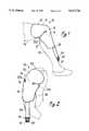
- FIG. 1is a perspective view of the conformable pad of the present invention positioned on the knee of a patient.
- FIG. 2is a perspective view of the conformable pad of the present invention positioned on the shoulder of a patient.
- FIG. 3is a bottom plan view of the conformable pad of the present invention.
- FIG. 4is a top plan view of the conformable pad of the present invention.
- FIG. 5is a cross-sectional elevational view of the conformable pad of the present invention taken along line 5--5 of FIG. 3.
- the pad of the present inventionis shown operatively positioned on the knee joint 12 of a patient being therapeutically treated.
- the pad 10comprises a planar member 14 having a main section 16, a connective section 18, an extension section 20.
- a pair of lateral nubs 22a, 22bextend from the main section 16 (although only nub 22a is visible in FIG. 1).
- the connective section 18rests directly atop the patella of knee joint 12 and conforms thereto.
- Main section 16fluid-communicatively engages connective section 18 and wraps around the lower leg 24 proximal knee joint 12 in conformance with the curvature thereof.
- the extension section 20likewise fluid-communicatively engages connective section 18 and conformingly wraps around the upper leg 26 proximal knee joint 12.
- Nub 22afits under extension section 20 to contact the lateral portion of knee joint 12.
- Pad 10further comprises an insulative sheath 28 extending rearwardly from the main section 16 of planar member 14.
- Sheath 28encases a pair of inlet and outlet tubes (not shown in FIG. 1, but described hereafter with reference to subsequent Figures).
- a male inlet valve coupling 30 and a male outlet valve coupling 32are shown in FIG. 1 extending rearwardly from sheath 28.
- a grip 34is provided to facilitate manual engagement and release of male valve couplings 32, 34 with corresponding female valve couplings of a fluid supply system (not shown).
- pad 10is shown operatively positioned on the shoulder joint 36 of a patient being therapeutically treated.
- the connective section 18rests directly on the tip of the shoulder joint 36 and conforms thereto.
- Main section 16wraps around the upper arm 38 proximal shoulder joint 36 in conformance with the curvature thereof.
- the extension section 20likewise conformingly wraps around the top 40 of shoulder joint 36.
- Nubs 22a and 22bfit under extension section 20 to contact the lateral portions of shoulder joint 36.
- pad 10The positioning of pad 10 on the knee joint 12 and shoulder joint 36 is shown in FIGS. 1 and 2 by way of example. It is apparent to one skilled in the art that pad 10 can be operatively positioned on other similarly contoured body parts, including the elbow and hip joints, in the same manner as set forth above. It is further noted that a conventional elastic wrap can be used to secure the position of pad 10 on the desired body part in a manner well known to one skilled in the art.
- pad 10The configuration and construction of pad 10 are described hereafter with reference to FIGS. 3-5.
- pad 10is described hereafter as laid out flat on a planar surface in a symmetrical configuration. Nevertheless, as noted above, the components of pad 10 are generally flexible and, thus, capable of assuming a number of different contoured configurations when the pad 10 is operational.
- the main section 16 of planar member 14has a quadrilateral-like shape with approximately linear forward and rearward borders that are substantially parallel to one another and perpendicular to the axis of symmetry of planar member 14.
- the rearward border of main section 16corresponds to the exposed rearward edge 42 of planar member 14, whereas the forward border of main section 16 extends between endpoints 44a and 44b, with only portions 46a and 46b of the forward border being exposed.
- the remaining portions 46c, 46d, and 46e of the forward borderfluid-communicatively engage arcuate-shaped lobular nubs 22a, 22b and connective section 18, respectively.
- Main section 16further has opposing lateral borders that correspond to the exposed lateral edges 48a and 48b of main section 16, respectively. Lateral edges 48a, 48b taper toward one another in the rearward direction. Accordingly, the length of the forward border, as defined by the distance between endpoints 44a, 44b, is greater than the length of the rearward border, as defined by the length of rearward edge 42.
- the extension section 20 of planar member 14has an oblong shape with rounded lateral borders and approximately linear forward and rearward borders that are substantially parallel to one another.
- the forward border of extension section 20corresponds to the exposed forward edge 50 of planar member 14, whereas the rearward border of extension section 20 extends between endpoints 52a and 52b, with only portions 54a and 54b being exposed.
- the remaining portion 54c of the rearward borderengages connective section 18.
- Extension section 20has a longitudinal axis extending between endpoints 56a, 56b.
- the longitudinal axis of extension section 20is aligned substantially perpendicular to and bisected by the axis of symmetry of planar member 14. the longitudinal axis is further aligned substantially parallel to the forward and rearward borders of main section 16, as well as substantially parallel to the forward and rearward borders of extension section 20.
- the longitudinal axishas a length, as defined by the distance between endpoints 56a, 56b, greater than or substantially equal to the length of the forward border of main section 16.
- connective section 18centrally engages main section 16 at the axis of symmetry of planar member 14 and continuously engages main section 16 in both lateral directions therefrom, across the entire portion 46e of its forward border which extends between portions 46a and 46b.
- connective section 18centrally engages extension section 20 at the axis of symmetry of planar member 14 and continuously engages extension section 20 in both lateral directions therefrom, across the entire portion 54c of its rearward border which extends between portions 54a and 54b.
- extension section 20as defined by the length of its longitudinal axis, and the width of the main section 16, as defined by the length of its forward border, are each greater than the width of the connective section 18, as determined at any point along its height. Accordingly, the widths of extension section 20 and main section 16 are each greater than the narrowmost width of connective section 18, shown herein to be the length of portion 46e, and are each likewise greater than the broadmost width of connective section 18, shown herein to be the length of portion 54c.
- the relative positioning of sections 16, 18, 20provides lateral void spaces 58a, 58b on opposite sides of connective section 18 between the forward border of main section 16 and the rearward border of extension section 20, respectively.
- the nubs 22a, 22bare arcuate-shaped, resembling lobes forwardly extending from portions 46c, 46d into void spaces 58a, 58b, respectively.
- the forward extension distance of each nub 22a, 22bis less than the height of connective section 20, as defined by the distance between portions 46e and 54c. Accordingly, nubs 22a, 22b do not close off lateral void spaces 58a, 58b, respectively when planar member 14 is in a flattened condition.
- planar member 14is shown to have a laminar construction, including an upper sheet 60 and a lower sheet 62 both formed from a thin flexible heat-conductive material, such as polyurethane.
- Lower sheet 62is shown in FIGS. 3 and 5 to be transparent and exposed so that it directly contacts the body when pad 10 is operatively positioned thereon.
- upper sheet 60is sandwiched between lower sheet 62 and a relatively thicker insulative layer 64 of a flexible foam that is bonded to upper sheet, as shown in FIGS. 4 and 5. Insulative layer 64 prevents heat loss to the surrounding atmosphere, or alternatively heat gain therefrom, depending on the temperature of the treatment fluid.
- the peripheries of sheets 60, 62are bonded to one another by duplicate thermal welding to substantially enclose the interior of sheets 60, 62 within a secure peripheral seam 66, thereby defining a bladder.
- a plurality of circular welds 68also bond sheets 60, 62 together at periodic points across the planar member surface. Consequently, a continuous fluid-communicative space remains between sheets 60, 62 where the sheets are not bonded to one another. This space constitutes an internal flow channel 70 for treatment fluid being circulated through pad 10.
- the circular welds 68function to limit the height of flow channel 70 when operating under elevated pressure, and also function to divert fluid flow in a tortuous path through flow channel 70.
- flow channel 70is delineated by a first linear flow divider 72 that is formed from a discrete linear weld, bonding sheets 60, 62 together along the length of the weld.
- the first flow divider 72is contained entirely within main section 16, and is aligned along the axis of symmetry of planar member 14, substantially perpendicular to the forward and rearward borders of main section 16 as well as the longitudinal axis of extension section 20.
- the flow divider 72engages seam 66 at the rearward edge 42 of the planar member to substantially prevent continuous fluid flow along edge 42.
- Flow channel 70is further delineated by a second discrete linear flow divider 74 formed in the same manner as flow divider 72.
- Second flow divider 74is in linear alignment with first flow divider 72 along the axis of symmetry of planar member 14, but is spaced a small distance apart from the first flow divider 72 to define a narrow breach 76 between flow dividers 72, 74.
- Second flow divider 74extends from extension section 20 through connective section 18 to main section 16, such that breach 76 is positioned within main section 16.
- narrow breach 76enables a limited degree of cross flow within the flow channel 70 of main section 16, thereby improving temperature distribution across planar member 14 during operation of the pad, and enabling continued operation of the pad 10 should kinks occur in sections 18, 20 or nubs 22a, 22b.
- Flow distribution within flow channel 70is also enhanced by providing orthogonally or diagonally oriented branches 78, 80 on the respective forward ends of first and second flow dividers 72, 74.
- An inlet port 82provides an opening in seam 66 at rearward edge 42 of planar member 14 slightly offset to one side of the first linear flow divider 72.
- a flexible inlet tube 84penetrates the internal flow channel 70 through inlet port 82 and is sealingly bonded to sheets 60, 62 proximal inlet port 82.
- Inlet tube 84extends rearwardly from inlet port 82 to selectively provide fluid communication between the internal flow channel 70 and the exterior of the pad 10.
- Valve coupling 30is biased in the closed position, but can be actively maintained open to provide fluid communication between the interior and exterior of the pad 10 by means of a corresponding female valve coupling (not shown) of the type disclosed in our above-referenced patent application.
- An outlet port 86is similarly provided in seam 66 substantially adjacent to inlet port 82, but slightly offset to the opposite side of the first linear flow divider 72.
- An outlet tube 88extends from outlet port 86 and likewise has a male shutoff valve coupling 32 across its exterior end. Both inlet and outlet tubes 84, 88 are enclosed, as shown by cut-away in FIG. 3, within the insulative sheath 28 preferably formed from a flexible foam.
- inlet tube 84 and outlet tubes 88are connected to a system (not shown) for driving a nonambient temperature therapeutic treatment fluid from a fluid reservoir, through the internal flow channel 70 of pad 10, and back to the reservoir.
- a systemfor driving a nonambient temperature therapeutic treatment fluid from a fluid reservoir, through the internal flow channel 70 of pad 10, and back to the reservoir.
Landscapes
- Health & Medical Sciences (AREA)
- Animal Behavior & Ethology (AREA)
- Public Health (AREA)
- Engineering & Computer Science (AREA)
- Biomedical Technology (AREA)
- Heart & Thoracic Surgery (AREA)
- Vascular Medicine (AREA)
- Veterinary Medicine (AREA)
- Life Sciences & Earth Sciences (AREA)
- General Health & Medical Sciences (AREA)
- Physics & Mathematics (AREA)
- Thermal Sciences (AREA)
- Nursing (AREA)
- Orthopedic Medicine & Surgery (AREA)
- Anesthesiology (AREA)
- Hematology (AREA)
- Thermotherapy And Cooling Therapy Devices (AREA)
Abstract
Description
Claims (19)
Priority Applications (1)
| Application Number | Priority Date | Filing Date | Title |
|---|---|---|---|
| US08/300,699US5417720A (en) | 1990-09-05 | 1994-09-02 | Nonambient temperature pad conformable to a body for therapeutic treatment thereof |
Applications Claiming Priority (6)
| Application Number | Priority Date | Filing Date | Title |
|---|---|---|---|
| US07/578,508US5080089A (en) | 1990-09-05 | 1990-09-05 | Therapeutic apparatus applying compression and a nonambient temperature fluid |
| US07767494US5241951B1 (en) | 1990-09-05 | 1991-09-30 | Therapeutic nonambient temperature fluid circulation system |
| US85134592A | 1992-03-12 | 1992-03-12 | |
| US07/906,407US5324319A (en) | 1990-09-05 | 1992-07-01 | Gravity driven therapeutic fluid circulation device |
| US6919593A | 1993-05-27 | 1993-05-27 | |
| US08/300,699US5417720A (en) | 1990-09-05 | 1994-09-02 | Nonambient temperature pad conformable to a body for therapeutic treatment thereof |
Related Parent Applications (1)
| Application Number | Title | Priority Date | Filing Date |
|---|---|---|---|
| US6919593AContinuation | 1990-09-05 | 1993-05-27 |
Publications (1)
| Publication Number | Publication Date |
|---|---|
| US5417720Atrue US5417720A (en) | 1995-05-23 |
Family
ID=27535814
Family Applications (1)
| Application Number | Title | Priority Date | Filing Date |
|---|---|---|---|
| US08/300,699Expired - LifetimeUS5417720A (en) | 1990-09-05 | 1994-09-02 | Nonambient temperature pad conformable to a body for therapeutic treatment thereof |
Country Status (1)
| Country | Link |
|---|---|
| US (1) | US5417720A (en) |
Cited By (84)
| Publication number | Priority date | Publication date | Assignee | Title |
|---|---|---|---|---|
| US5651757A (en)* | 1996-02-15 | 1997-07-29 | Meckstroth; Clyde S. | Endoscope warmer |
| US6109338A (en)* | 1997-05-01 | 2000-08-29 | Oceaneering International, Inc. | Article comprising a garment or other textile structure for use in controlling body temperature |
| US6117164A (en) | 1997-06-06 | 2000-09-12 | Dj Orthopedics, Llc | Flexible multijoint therapeutic pads |
| US6238427B1 (en) | 1999-03-30 | 2001-05-29 | John G. Matta | Therapeutic heat transfer pads |
| US6279338B1 (en)* | 2000-02-19 | 2001-08-28 | Samir Badry Mohamed | Cold compresses apparatus |
| US6375673B1 (en)* | 1998-04-23 | 2002-04-23 | The Board Of Regents Of The University Of Texas System | Heat transfer blanket for and method of controlling a patient's temperature |
| US20040068310A1 (en)* | 2002-10-08 | 2004-04-08 | Howard Edelman | Therapy pad |
| US20040158303A1 (en)* | 2002-04-29 | 2004-08-12 | Medcool, Inc. | Method and device for rapidly inducing and then maintaining hypothermia |
| USD500140S1 (en) | 2003-08-29 | 2004-12-21 | Dj Orthopedics, Llc | Thermal therapy pad |
| USD505727S1 (en) | 2003-08-29 | 2005-05-31 | Dj Orthopedics, Llc | Thermal therapy pad |
| US20050143797A1 (en)* | 2003-07-18 | 2005-06-30 | Thermotek, Inc. | Compression sequenced thermal therapy system |
| USD510626S1 (en) | 2003-08-29 | 2005-10-11 | Dj Orthopedics, Llc | Thermal therapy pad |
| US20050256556A1 (en)* | 2004-05-17 | 2005-11-17 | Coolsystems, Inc. | Modular apparatus for therapy of an animate body |
| US20060030915A1 (en)* | 2003-08-04 | 2006-02-09 | Medcool, Inc. | Method and apparatus for reducing body temperature of a subject |
| USD515218S1 (en) | 2004-01-22 | 2006-02-14 | Dj Orthopedics, Llc | Thermal therapy pad |
| US7008445B2 (en) | 2002-04-29 | 2006-03-07 | Medcool, Inc. | Method and device for rapidly inducing hypothermia |
| USD527108S1 (en) | 2003-10-10 | 2006-08-22 | Dj Orthopedics, Llc | Thermal therapy pad |
| USD532523S1 (en) | 2003-08-29 | 2006-11-21 | Dj Orthopedics, Llc | Thermal therapy pad |
| US7198093B1 (en) | 1998-07-31 | 2007-04-03 | Coolsystems, Inc. | Compliant heat exchange panel |
| US20070112401A1 (en)* | 2005-10-14 | 2007-05-17 | Niran Balachandran | Critical care thermal therapy method and system |
| US20070118194A1 (en)* | 2005-11-22 | 2007-05-24 | Breg, Inc. | Non-ambient temperature therapy system with automatic treatment temperature maintenance |
| US20070282249A1 (en)* | 2006-05-09 | 2007-12-06 | Tony Quisenberry | Method of and system for thermally augmented wound care oxygenation |
| US20080021531A1 (en)* | 2003-09-24 | 2008-01-24 | Kane John R | Methods and apparatus for increasing blood circulation |
| US20080097561A1 (en)* | 2006-10-18 | 2008-04-24 | Medcool, Inc. | Dual cycle thermal system and method of use |
| US20080132816A1 (en)* | 2006-12-04 | 2008-06-05 | Kane John Roy | Methods and Apparatus for Adjusting Blood Circulation |
| US20080132976A1 (en)* | 2006-12-04 | 2008-06-05 | Kane John Roy | Methods and apparatus for adjusting blood circulation |
| US20080249593A1 (en)* | 2007-04-05 | 2008-10-09 | Cazzini Karl H | Negative/positive pressure, thermal energy therapy device |
| US20080269852A1 (en)* | 2005-04-07 | 2008-10-30 | Medcool, Inc | Methods and Apparatus for Thermal Regulation of a Body |
| EP1073388B1 (en)* | 1998-04-23 | 2008-11-05 | The Board of Regents of the University of Texas System | Heat transfer blanket for and method of controlling a patient's temperature |
| US20080288033A1 (en)* | 2007-05-14 | 2008-11-20 | Mason Jeffrey T | Heat transfer pad having occlusion-resistant ports |
| US20090048649A1 (en)* | 2007-08-16 | 2009-02-19 | Gaymar Industries, Inc. | Heat transfer device: seal and thermal energy contact units |
| US20090066079A1 (en)* | 2007-09-12 | 2009-03-12 | Coolsystems, Inc. | Make-brake connector assembly with opposing latches |
| US20090109622A1 (en)* | 2004-08-12 | 2009-04-30 | Parish Overton L | Thermal control system for rack mounting |
| US20100030306A1 (en)* | 2002-10-08 | 2010-02-04 | Howard Edelman | Therapeutic Cranial Wrap for a Contrast Therapy System |
| US7658205B1 (en) | 2002-12-19 | 2010-02-09 | Vitalwear, Inc. | Systems for a fluid circuit coupler |
| US7694693B1 (en) | 2002-10-08 | 2010-04-13 | Vitalwear, Inc. | Mixing valve for a contrast therapy system |
| US20100137951A1 (en)* | 2002-12-12 | 2010-06-03 | Medcool, Inc. | Method and apparatus for reducing body temperature of a subject |
| US20100139294A1 (en)* | 2008-12-05 | 2010-06-10 | Coolsystems, Inc. | Cooling System Having A Bypass Valve To Regulate Fluid Flow |
| US20100145421A1 (en)* | 2008-12-05 | 2010-06-10 | Coolsystems, Inc. | Therapeutic Cooling and/or Heating System Including A Thermo-Conductive Material |
| US7837638B2 (en) | 2007-02-13 | 2010-11-23 | Coolsystems, Inc. | Flexible joint wrap |
| US20110009898A1 (en)* | 2009-07-13 | 2011-01-13 | Wei-Hua Lu | Pressure Bandage |
| US20110098792A1 (en)* | 2009-10-22 | 2011-04-28 | Lowe Mark H | Therapeutic wrap |
| US20110106023A1 (en)* | 2009-11-04 | 2011-05-05 | Lowe Mark H | System for providing treatment to a mammal |
| US20110172749A1 (en)* | 2010-01-08 | 2011-07-14 | Christensen Scott A | Methods and apparatus for enhancing vascular access in an appendage to enhance therapeutic and interventional procedures |
| US8052628B1 (en) | 2002-10-08 | 2011-11-08 | Vitalwear, Inc. | Spinal column brace for a contrast therapy system |
| US8066752B2 (en) | 2003-09-24 | 2011-11-29 | Dynatherm Medical, Inc. | Methods and apparatus for adjusting body core temperature |
| US8128672B2 (en) | 2006-05-09 | 2012-03-06 | Thermotek, Inc. | Wound care method and system with one or both of vacuum-light therapy and thermally augmented oxygenation |
| USD662212S1 (en) | 2007-04-10 | 2012-06-19 | Thermotek, Inc. | Butterfly wrap |
| US20120288848A1 (en)* | 2011-01-20 | 2012-11-15 | Traumatec, Inc. | Multi-Dimensional Flow Pad Technology for Covering Three-Dimensional Dome Shaped Anatomies |
| USD679023S1 (en) | 2004-07-19 | 2013-03-26 | Thermotek, Inc. | Foot wrap |
| US8425579B1 (en) | 2002-10-08 | 2013-04-23 | Vitalwear, Inc. | Therapeutic knee brace for a contrast therapy system |
| JP2013126523A (en)* | 2011-11-16 | 2013-06-27 | Raito Koki Seisakusho:Kk | Liquid retainer, and cooling and heating apparatus |
| US8529613B2 (en) | 2006-10-18 | 2013-09-10 | Medcool, Inc. | Adjustable thermal cap |
| US8574278B2 (en) | 2006-05-09 | 2013-11-05 | Thermotek, Inc. | Wound care method and system with one or both of vacuum-light therapy and thermally augmented oxygenation |
| US8597217B2 (en) | 2010-12-30 | 2013-12-03 | Coolsystems, Inc. | Reinforced therapeutic wrap and method |
| US20140012169A1 (en)* | 2012-07-09 | 2014-01-09 | Michael L. Wilford | Therapeutic wrap |
| US8758419B1 (en) | 2008-01-31 | 2014-06-24 | Thermotek, Inc. | Contact cooler for skin cooling applications |
| US8778005B2 (en) | 2003-07-18 | 2014-07-15 | Thermotek, Inc. | Method and system for thermal and compression therapy relative to the prevention of deep vein thrombosis |
| US20150173942A1 (en)* | 2013-12-20 | 2015-06-25 | Rapid Aid Corp. | Thermotherapeutic pad with beads in textured envelope |
| US9119705B2 (en) | 1998-06-08 | 2015-09-01 | Thermotek, Inc. | Method and system for thermal and compression therapy relative to the prevention of deep vein thrombosis |
| US9125787B2 (en) | 2011-09-30 | 2015-09-08 | Covidien Lp | Compression garment having a foam layer |
| US9170059B2 (en) | 2011-01-14 | 2015-10-27 | Breg, Inc. | Heat transfer pad having localized treatment zones |
| US20160076830A1 (en)* | 2014-09-16 | 2016-03-17 | Jennifer Repp | Climate controlling mechanisms for car seats/strollers |
| USD757286S1 (en) | 2014-07-07 | 2016-05-24 | Deroyal Industries, Inc. | Thermal therapy blanket |
| USD757954S1 (en) | 2014-07-07 | 2016-05-31 | Deroyal Industries, Inc. | Thermal therapy blanket |
| US9402779B2 (en) | 2013-03-11 | 2016-08-02 | Covidien Lp | Compression garment with perspiration relief |
| US9615967B2 (en) | 2010-12-30 | 2017-04-11 | Coolsystems, Inc. | Reinforced therapeutic wrap and method |
| US9669233B2 (en) | 2013-11-11 | 2017-06-06 | Thermotek, Inc. | Method and system for wound care |
| US9930728B2 (en)* | 2011-01-03 | 2018-03-27 | Textron Innovations Inc. | Vacuum assisted conformal shape setting device |
| US10016583B2 (en) | 2013-03-11 | 2018-07-10 | Thermotek, Inc. | Wound care and infusion method and system utilizing a thermally-treated therapeutic agent |
| US10149927B2 (en) | 2012-04-24 | 2018-12-11 | Thermotek, Inc. | Method and system for therapeutic use of ultra-violet light |
| US10300180B1 (en) | 2013-03-11 | 2019-05-28 | Thermotek, Inc. | Wound care and infusion method and system utilizing a therapeutic agent |
| US10456320B2 (en) | 2013-10-01 | 2019-10-29 | Coolsystems, Inc. | Hand and foot wraps |
| US10463565B2 (en) | 2011-06-17 | 2019-11-05 | Coolsystems, Inc. | Adjustable patient therapy device |
| US10512587B2 (en) | 2011-07-27 | 2019-12-24 | Thermotek, Inc. | Method and apparatus for scalp thermal treatment |
| US10765785B2 (en) | 2004-07-19 | 2020-09-08 | Thermotek, Inc. | Wound care and infusion method and system utilizing a therapeutic agent |
| US10859295B2 (en) | 2016-04-13 | 2020-12-08 | ZeoThermal Technologies, LLC | Cooling and heating platform |
| WO2021184872A1 (en)* | 2020-03-18 | 2021-09-23 | 锐可医疗科技(苏州)有限公司 | Cold and hot compress pack and manufacturing method therefor, and cold and hot compress circulation system |
| US11285037B1 (en) | 2020-08-13 | 2022-03-29 | Evolve Orthopedics LLC | Mobile cold therapy device |
| US11622882B1 (en) | 2020-08-13 | 2023-04-11 | Evolve Orthopedics LLC | Mobile cold therapy device |
| US11638675B2 (en) | 2018-11-07 | 2023-05-02 | Zenith Technical Innovations, Llc | System and method for heat or cold therapy and compression therapy |
| US11672693B2 (en) | 2014-08-05 | 2023-06-13 | Avent, Inc. | Integrated multisectional heat exchanger |
| US11813194B2 (en)* | 2017-03-06 | 2023-11-14 | Board Of Regents, The University Of Texas System | Water perfusion heat exchange pad for control of skin temperature |
| US20240156669A1 (en)* | 2021-06-25 | 2024-05-16 | Aquilo Sports Llc | Therapeutic pressure, thermal, and/or other treatment modality systems and methods |
Citations (7)
| Publication number | Priority date | Publication date | Assignee | Title |
|---|---|---|---|---|
| US4061898A (en)* | 1976-08-16 | 1977-12-06 | Redken Laboratories, Inc. | Heat cap |
| US4108146A (en)* | 1977-05-16 | 1978-08-22 | Theodore Alan Golden | Bendable thermal pack unit |
| US4357009A (en)* | 1980-06-18 | 1982-11-02 | Baker Phillip L | Water-filled weight bag |
| US4753242A (en)* | 1985-01-28 | 1988-06-28 | Saggers Michael J | Skull helmet for circulating cooling fluid |
| US4947843A (en)* | 1989-02-21 | 1990-08-14 | Pioneering Technologies, Inc. | Cardiac insulator |
| US5014695A (en)* | 1988-10-04 | 1991-05-14 | Benak Arnold M | Kidney cooling jacket |
| US5086771A (en)* | 1991-09-05 | 1992-02-11 | Cincinnati Sub-Zero Products, Inc. | Configured pad for therapeutic cooling effect |
- 1994
- 1994-09-02USUS08/300,699patent/US5417720A/ennot_activeExpired - Lifetime
Patent Citations (7)
| Publication number | Priority date | Publication date | Assignee | Title |
|---|---|---|---|---|
| US4061898A (en)* | 1976-08-16 | 1977-12-06 | Redken Laboratories, Inc. | Heat cap |
| US4108146A (en)* | 1977-05-16 | 1978-08-22 | Theodore Alan Golden | Bendable thermal pack unit |
| US4357009A (en)* | 1980-06-18 | 1982-11-02 | Baker Phillip L | Water-filled weight bag |
| US4753242A (en)* | 1985-01-28 | 1988-06-28 | Saggers Michael J | Skull helmet for circulating cooling fluid |
| US5014695A (en)* | 1988-10-04 | 1991-05-14 | Benak Arnold M | Kidney cooling jacket |
| US4947843A (en)* | 1989-02-21 | 1990-08-14 | Pioneering Technologies, Inc. | Cardiac insulator |
| US5086771A (en)* | 1991-09-05 | 1992-02-11 | Cincinnati Sub-Zero Products, Inc. | Configured pad for therapeutic cooling effect |
Cited By (138)
| Publication number | Priority date | Publication date | Assignee | Title |
|---|---|---|---|---|
| US5651757A (en)* | 1996-02-15 | 1997-07-29 | Meckstroth; Clyde S. | Endoscope warmer |
| US6109338A (en)* | 1997-05-01 | 2000-08-29 | Oceaneering International, Inc. | Article comprising a garment or other textile structure for use in controlling body temperature |
| US6117164A (en) | 1997-06-06 | 2000-09-12 | Dj Orthopedics, Llc | Flexible multijoint therapeutic pads |
| US6352550B1 (en) | 1997-06-06 | 2002-03-05 | Dj Orthopedics, Llc | Flexible multijoint therapeutic pads |
| US6375673B1 (en)* | 1998-04-23 | 2002-04-23 | The Board Of Regents Of The University Of Texas System | Heat transfer blanket for and method of controlling a patient's temperature |
| EP1073388B1 (en)* | 1998-04-23 | 2008-11-05 | The Board of Regents of the University of Texas System | Heat transfer blanket for and method of controlling a patient's temperature |
| US9877864B2 (en) | 1998-06-08 | 2018-01-30 | Thermotek, Inc. | Compression sequenced thermal therapy system |
| US10507131B2 (en) | 1998-06-08 | 2019-12-17 | Thermotek, Inc. | Method and system for thermal and compression therapy relative to the prevention of deep vein thrombosis |
| US9119705B2 (en) | 1998-06-08 | 2015-09-01 | Thermotek, Inc. | Method and system for thermal and compression therapy relative to the prevention of deep vein thrombosis |
| US9180041B2 (en) | 1998-06-08 | 2015-11-10 | Thermotek, Inc. | Compression sequenced thermal therapy system |
| US9433525B2 (en) | 1998-06-08 | 2016-09-06 | Thermotek, Inc. | Compression sequenced thermal therapy system |
| US7198093B1 (en) | 1998-07-31 | 2007-04-03 | Coolsystems, Inc. | Compliant heat exchange panel |
| US6238427B1 (en) | 1999-03-30 | 2001-05-29 | John G. Matta | Therapeutic heat transfer pads |
| US6279338B1 (en)* | 2000-02-19 | 2001-08-28 | Samir Badry Mohamed | Cold compresses apparatus |
| US20040158303A1 (en)* | 2002-04-29 | 2004-08-12 | Medcool, Inc. | Method and device for rapidly inducing and then maintaining hypothermia |
| US7507250B2 (en) | 2002-04-29 | 2009-03-24 | Medcool, Inc. | Method and device for rapidly inducing hypothermia |
| US7008445B2 (en) | 2002-04-29 | 2006-03-07 | Medcool, Inc. | Method and device for rapidly inducing hypothermia |
| US20060074469A1 (en)* | 2002-04-29 | 2006-04-06 | Medcool, Inc. | Method and apparatus for reducing body temperature of a subject |
| US7052509B2 (en) | 2002-04-29 | 2006-05-30 | Medcool, Inc. | Method and device for rapidly inducing and then maintaining hypothermia |
| US7621945B2 (en) | 2002-04-29 | 2009-11-24 | Medcool, Inc. | Method and apparatus for reducing body temperature of a subject |
| US20040068310A1 (en)* | 2002-10-08 | 2004-04-08 | Howard Edelman | Therapy pad |
| US20100030306A1 (en)* | 2002-10-08 | 2010-02-04 | Howard Edelman | Therapeutic Cranial Wrap for a Contrast Therapy System |
| US7211104B2 (en) | 2002-10-08 | 2007-05-01 | Vital Wear, Inc. | Contrast therapy system and method |
| US7694693B1 (en) | 2002-10-08 | 2010-04-13 | Vitalwear, Inc. | Mixing valve for a contrast therapy system |
| US8425579B1 (en) | 2002-10-08 | 2013-04-23 | Vitalwear, Inc. | Therapeutic knee brace for a contrast therapy system |
| US8226698B2 (en) | 2002-10-08 | 2012-07-24 | Vitalwear, Inc. | Therapeutic cranial wrap for a contrast therapy system |
| US8052628B1 (en) | 2002-10-08 | 2011-11-08 | Vitalwear, Inc. | Spinal column brace for a contrast therapy system |
| US20100137951A1 (en)* | 2002-12-12 | 2010-06-03 | Medcool, Inc. | Method and apparatus for reducing body temperature of a subject |
| US8454671B2 (en) | 2002-12-12 | 2013-06-04 | Medcool, Inc. | Method and apparatus for reducing body temperature of a subject |
| US7658205B1 (en) | 2002-12-19 | 2010-02-09 | Vitalwear, Inc. | Systems for a fluid circuit coupler |
| US10507140B2 (en) | 2003-07-18 | 2019-12-17 | Thermotek, Inc. | Wound care method and system with one or both of vacuum-light therapy and thermally augmented oxygenation |
| US8778005B2 (en) | 2003-07-18 | 2014-07-15 | Thermotek, Inc. | Method and system for thermal and compression therapy relative to the prevention of deep vein thrombosis |
| US9616210B2 (en) | 2003-07-18 | 2017-04-11 | Thermotek, Inc. | Wound care method and system with one or both of vacuum-light therapy and thermally augmented oxygenation |
| US20050143797A1 (en)* | 2003-07-18 | 2005-06-30 | Thermotek, Inc. | Compression sequenced thermal therapy system |
| US8425580B2 (en) | 2003-07-18 | 2013-04-23 | Thermotek, Inc. | Method of and system for thermally augmented wound care oxygenation |
| US8753383B2 (en) | 2003-07-18 | 2014-06-17 | Thermotek, Inc. | Compression sequenced thermal therapy system |
| US9192539B2 (en) | 2003-07-18 | 2015-11-24 | Thermotek, Inc. | Method and system for thermal and compression therapy relative to the prevention of deep vein thrombosis |
| US20060030915A1 (en)* | 2003-08-04 | 2006-02-09 | Medcool, Inc. | Method and apparatus for reducing body temperature of a subject |
| USD510626S1 (en) | 2003-08-29 | 2005-10-11 | Dj Orthopedics, Llc | Thermal therapy pad |
| USD500140S1 (en) | 2003-08-29 | 2004-12-21 | Dj Orthopedics, Llc | Thermal therapy pad |
| USD532523S1 (en) | 2003-08-29 | 2006-11-21 | Dj Orthopedics, Llc | Thermal therapy pad |
| USD505727S1 (en) | 2003-08-29 | 2005-05-31 | Dj Orthopedics, Llc | Thermal therapy pad |
| US8066752B2 (en) | 2003-09-24 | 2011-11-29 | Dynatherm Medical, Inc. | Methods and apparatus for adjusting body core temperature |
| US8182521B2 (en) | 2003-09-24 | 2012-05-22 | Dynatherm Medical Inc. | Methods and apparatus for increasing blood circulation |
| US20080021531A1 (en)* | 2003-09-24 | 2008-01-24 | Kane John R | Methods and apparatus for increasing blood circulation |
| USD527108S1 (en) | 2003-10-10 | 2006-08-22 | Dj Orthopedics, Llc | Thermal therapy pad |
| USD515218S1 (en) | 2004-01-22 | 2006-02-14 | Dj Orthopedics, Llc | Thermal therapy pad |
| US20090005841A1 (en)* | 2004-05-17 | 2009-01-01 | Tamara Lynn Schirrmacher | Modular apparatus for therapy of an animate body |
| US20050256556A1 (en)* | 2004-05-17 | 2005-11-17 | Coolsystems, Inc. | Modular apparatus for therapy of an animate body |
| US20110152983A1 (en)* | 2004-05-17 | 2011-06-23 | Tamara Lynn Schirrmacher | Modular apparatus for therapy of an animate body |
| US7896910B2 (en) | 2004-05-17 | 2011-03-01 | Coolsystems, Inc. | Modular apparatus for therapy of an animate body |
| US11013635B2 (en) | 2004-05-17 | 2021-05-25 | Coolsystems, Inc. | Modular apparatus for therapy of an animate body |
| USD679023S1 (en) | 2004-07-19 | 2013-03-26 | Thermotek, Inc. | Foot wrap |
| US8940034B2 (en) | 2004-07-19 | 2015-01-27 | Thermotek, Inc. | Wound care method and system with one or both of vacuum-light therapy and thermally augmented oxygenation |
| US10765785B2 (en) | 2004-07-19 | 2020-09-08 | Thermotek, Inc. | Wound care and infusion method and system utilizing a therapeutic agent |
| US8248798B2 (en) | 2004-08-12 | 2012-08-21 | Thermotek, Inc. | Thermal control system for rack mounting |
| US20090109622A1 (en)* | 2004-08-12 | 2009-04-30 | Parish Overton L | Thermal control system for rack mounting |
| US7804686B2 (en) | 2004-08-12 | 2010-09-28 | Thermotek, Inc. | Thermal control system for rack mounting |
| US20080269852A1 (en)* | 2005-04-07 | 2008-10-30 | Medcool, Inc | Methods and Apparatus for Thermal Regulation of a Body |
| US7909861B2 (en) | 2005-10-14 | 2011-03-22 | Thermotek, Inc. | Critical care thermal therapy method and system |
| US20070112401A1 (en)* | 2005-10-14 | 2007-05-17 | Niran Balachandran | Critical care thermal therapy method and system |
| US20070118194A1 (en)* | 2005-11-22 | 2007-05-24 | Breg, Inc. | Non-ambient temperature therapy system with automatic treatment temperature maintenance |
| US8574278B2 (en) | 2006-05-09 | 2013-11-05 | Thermotek, Inc. | Wound care method and system with one or both of vacuum-light therapy and thermally augmented oxygenation |
| US8142486B2 (en) | 2006-05-09 | 2012-03-27 | Thermotek, Inc. | Wound care method and system with one or both of vacuum-light therapy and thermally augmented oxygenation |
| US8128672B2 (en) | 2006-05-09 | 2012-03-06 | Thermotek, Inc. | Wound care method and system with one or both of vacuum-light therapy and thermally augmented oxygenation |
| US8100956B2 (en) | 2006-05-09 | 2012-01-24 | Thermotek, Inc. | Method of and system for thermally augmented wound care oxygenation |
| US10507311B2 (en) | 2006-05-09 | 2019-12-17 | Thermotek, Inc. | Wound care method and system with one or both of vacuum-light therapy and thermally augmented oxygenation |
| US8632576B2 (en) | 2006-05-09 | 2014-01-21 | Thermotek, Inc. | Wound care method and system with one or both of vacuum-light therapy and thermally augmented oxygenation |
| US9950148B2 (en) | 2006-05-09 | 2018-04-24 | Thermotek, Inc. | Wound care method and system with one or both of vacuum-light therapy and thermally augmented oxygenation |
| US20070282249A1 (en)* | 2006-05-09 | 2007-12-06 | Tony Quisenberry | Method of and system for thermally augmented wound care oxygenation |
| US8529613B2 (en) | 2006-10-18 | 2013-09-10 | Medcool, Inc. | Adjustable thermal cap |
| US20080097561A1 (en)* | 2006-10-18 | 2008-04-24 | Medcool, Inc. | Dual cycle thermal system and method of use |
| US20080132976A1 (en)* | 2006-12-04 | 2008-06-05 | Kane John Roy | Methods and apparatus for adjusting blood circulation |
| US20080132816A1 (en)* | 2006-12-04 | 2008-06-05 | Kane John Roy | Methods and Apparatus for Adjusting Blood Circulation |
| US10350134B2 (en) | 2006-12-04 | 2019-07-16 | Avacore Technologies, Inc. | Methods and apparatus for adjusting blood circulation |
| US9308148B2 (en) | 2006-12-04 | 2016-04-12 | Thermatx, Inc. | Methods and apparatus for adjusting blood circulation |
| US8603150B2 (en) | 2006-12-04 | 2013-12-10 | Carefusion 2200, Inc. | Methods and apparatus for adjusting blood circulation |
| US11324656B2 (en) | 2006-12-04 | 2022-05-10 | Avacore Technologies, Inc. | Methods and apparatus for adjusting blood circulation |
| US7837638B2 (en) | 2007-02-13 | 2010-11-23 | Coolsystems, Inc. | Flexible joint wrap |
| US20110028873A1 (en)* | 2007-02-13 | 2011-02-03 | Miros Robert H J | Flexible joint wrap |
| US9980844B2 (en) | 2007-02-13 | 2018-05-29 | Coolsystems, Inc. | Flexible joint wrap |
| US8460355B2 (en) | 2007-04-05 | 2013-06-11 | Stryker Corporation | Negative/positive pressure, thermal energy therapy device |
| US20080249593A1 (en)* | 2007-04-05 | 2008-10-09 | Cazzini Karl H | Negative/positive pressure, thermal energy therapy device |
| USD662214S1 (en) | 2007-04-10 | 2012-06-19 | Thermotek, Inc. | Circumferential leg wrap |
| USD683042S1 (en) | 2007-04-10 | 2013-05-21 | Thermotek, Inc. | Calf wrap |
| USD664260S1 (en) | 2007-04-10 | 2012-07-24 | Thermotek, Inc. | Calf wrap |
| USD662213S1 (en) | 2007-04-10 | 2012-06-19 | Thermotek, Inc. | Knee wrap |
| USD662212S1 (en) | 2007-04-10 | 2012-06-19 | Thermotek, Inc. | Butterfly wrap |
| US20080288033A1 (en)* | 2007-05-14 | 2008-11-20 | Mason Jeffrey T | Heat transfer pad having occlusion-resistant ports |
| US7914563B2 (en) | 2007-05-14 | 2011-03-29 | Breg, Inc. | Heat transfer pad having occlusion-resistant ports |
| US20090048649A1 (en)* | 2007-08-16 | 2009-02-19 | Gaymar Industries, Inc. | Heat transfer device: seal and thermal energy contact units |
| US7731244B2 (en) | 2007-09-12 | 2010-06-08 | Coolsystems, Inc. | Make-brake connector assembly with opposing latches |
| US20090066079A1 (en)* | 2007-09-12 | 2009-03-12 | Coolsystems, Inc. | Make-brake connector assembly with opposing latches |
| US8758419B1 (en) | 2008-01-31 | 2014-06-24 | Thermotek, Inc. | Contact cooler for skin cooling applications |
| US20100139294A1 (en)* | 2008-12-05 | 2010-06-10 | Coolsystems, Inc. | Cooling System Having A Bypass Valve To Regulate Fluid Flow |
| US20100145421A1 (en)* | 2008-12-05 | 2010-06-10 | Coolsystems, Inc. | Therapeutic Cooling and/or Heating System Including A Thermo-Conductive Material |
| US20110009898A1 (en)* | 2009-07-13 | 2011-01-13 | Wei-Hua Lu | Pressure Bandage |
| US8715330B2 (en) | 2009-10-22 | 2014-05-06 | Coolsystems, Inc. | Temperature and flow control methods in a thermal therapy device |
| US20110098792A1 (en)* | 2009-10-22 | 2011-04-28 | Lowe Mark H | Therapeutic wrap |
| US9943437B2 (en) | 2009-10-22 | 2018-04-17 | Coolsystems, Inc. | Temperature and flow control methods in a thermal therapy device |
| US20110106023A1 (en)* | 2009-11-04 | 2011-05-05 | Lowe Mark H | System for providing treatment to a mammal |
| US20110172749A1 (en)* | 2010-01-08 | 2011-07-14 | Christensen Scott A | Methods and apparatus for enhancing vascular access in an appendage to enhance therapeutic and interventional procedures |
| US8771329B2 (en) | 2010-01-08 | 2014-07-08 | Carefusion 2200, Inc. | Methods and apparatus for enhancing vascular access in an appendage to enhance therapeutic and interventional procedures |
| US11547625B2 (en) | 2010-12-30 | 2023-01-10 | Avent, Inc. | Reinforced therapeutic wrap and method |
| US8597217B2 (en) | 2010-12-30 | 2013-12-03 | Coolsystems, Inc. | Reinforced therapeutic wrap and method |
| US9615967B2 (en) | 2010-12-30 | 2017-04-11 | Coolsystems, Inc. | Reinforced therapeutic wrap and method |
| US9930728B2 (en)* | 2011-01-03 | 2018-03-27 | Textron Innovations Inc. | Vacuum assisted conformal shape setting device |
| US9170059B2 (en) | 2011-01-14 | 2015-10-27 | Breg, Inc. | Heat transfer pad having localized treatment zones |
| US20120288848A1 (en)* | 2011-01-20 | 2012-11-15 | Traumatec, Inc. | Multi-Dimensional Flow Pad Technology for Covering Three-Dimensional Dome Shaped Anatomies |
| US10463565B2 (en) | 2011-06-17 | 2019-11-05 | Coolsystems, Inc. | Adjustable patient therapy device |
| US10512587B2 (en) | 2011-07-27 | 2019-12-24 | Thermotek, Inc. | Method and apparatus for scalp thermal treatment |
| US9125787B2 (en) | 2011-09-30 | 2015-09-08 | Covidien Lp | Compression garment having a foam layer |
| JP2013126523A (en)* | 2011-11-16 | 2013-06-27 | Raito Koki Seisakusho:Kk | Liquid retainer, and cooling and heating apparatus |
| US10149927B2 (en) | 2012-04-24 | 2018-12-11 | Thermotek, Inc. | Method and system for therapeutic use of ultra-violet light |
| US20140012169A1 (en)* | 2012-07-09 | 2014-01-09 | Michael L. Wilford | Therapeutic wrap |
| US9132057B2 (en)* | 2012-07-09 | 2015-09-15 | Michael L. Wilford | Therapeutic wrap |
| US10918843B2 (en) | 2013-03-11 | 2021-02-16 | Thermotek, Inc. | Wound care and infusion method and system utilizing a thermally-treated therapeutic agent |
| US10300180B1 (en) | 2013-03-11 | 2019-05-28 | Thermotek, Inc. | Wound care and infusion method and system utilizing a therapeutic agent |
| US9402779B2 (en) | 2013-03-11 | 2016-08-02 | Covidien Lp | Compression garment with perspiration relief |
| US10016583B2 (en) | 2013-03-11 | 2018-07-10 | Thermotek, Inc. | Wound care and infusion method and system utilizing a thermally-treated therapeutic agent |
| US10456320B2 (en) | 2013-10-01 | 2019-10-29 | Coolsystems, Inc. | Hand and foot wraps |
| US9669233B2 (en) | 2013-11-11 | 2017-06-06 | Thermotek, Inc. | Method and system for wound care |
| US10272258B2 (en) | 2013-11-11 | 2019-04-30 | Thermotek, Inc. | Method and system for wound care |
| US20150173942A1 (en)* | 2013-12-20 | 2015-06-25 | Rapid Aid Corp. | Thermotherapeutic pad with beads in textured envelope |
| US10632011B2 (en)* | 2013-12-20 | 2020-04-28 | Rapid Aid Corp. | Thermotherapeutic pad with beads in textured envelope |
| USD757286S1 (en) | 2014-07-07 | 2016-05-24 | Deroyal Industries, Inc. | Thermal therapy blanket |
| USD757954S1 (en) | 2014-07-07 | 2016-05-31 | Deroyal Industries, Inc. | Thermal therapy blanket |
| US11672693B2 (en) | 2014-08-05 | 2023-06-13 | Avent, Inc. | Integrated multisectional heat exchanger |
| US10392044B2 (en)* | 2014-09-16 | 2019-08-27 | Jennifer Repp | Climate controlling mechanisms for car seats/strollers |
| US20160076830A1 (en)* | 2014-09-16 | 2016-03-17 | Jennifer Repp | Climate controlling mechanisms for car seats/strollers |
| US10859295B2 (en) | 2016-04-13 | 2020-12-08 | ZeoThermal Technologies, LLC | Cooling and heating platform |
| US11813194B2 (en)* | 2017-03-06 | 2023-11-14 | Board Of Regents, The University Of Texas System | Water perfusion heat exchange pad for control of skin temperature |
| US11638675B2 (en) | 2018-11-07 | 2023-05-02 | Zenith Technical Innovations, Llc | System and method for heat or cold therapy and compression therapy |
| WO2021184872A1 (en)* | 2020-03-18 | 2021-09-23 | 锐可医疗科技(苏州)有限公司 | Cold and hot compress pack and manufacturing method therefor, and cold and hot compress circulation system |
| US11285037B1 (en) | 2020-08-13 | 2022-03-29 | Evolve Orthopedics LLC | Mobile cold therapy device |
| US11622882B1 (en) | 2020-08-13 | 2023-04-11 | Evolve Orthopedics LLC | Mobile cold therapy device |
| US12070412B1 (en) | 2020-08-13 | 2024-08-27 | Evolve Orthopedics LLC | Mobile cold therapy device |
| US20240156669A1 (en)* | 2021-06-25 | 2024-05-16 | Aquilo Sports Llc | Therapeutic pressure, thermal, and/or other treatment modality systems and methods |
Similar Documents
| Publication | Publication Date | Title |
|---|---|---|
| US5417720A (en) | Nonambient temperature pad conformable to a body for therapeutic treatment thereof | |
| US5662695A (en) | Occlusion-resistant fluid pad conformable to a body for therapeutic treatment thereof | |
| US6352550B1 (en) | Flexible multijoint therapeutic pads | |
| US6551347B1 (en) | Cooling/heating system | |
| US7914563B2 (en) | Heat transfer pad having occlusion-resistant ports | |
| US5470353A (en) | Post-operative thermal blanket | |
| US9170059B2 (en) | Heat transfer pad having localized treatment zones | |
| US5466250A (en) | Automatic fluid compress and circulating system | |
| US6371976B1 (en) | Body temperature control for use with patient supports | |
| US6648905B2 (en) | Enhanced medical thermal energy exchange pad | |
| US5507792A (en) | Therapeutic treatment device having a heat transfer element and a pump for circulating a treatment fluid therethrough | |
| US6669715B2 (en) | Medical thermal energy exchange pad | |
| US5989285A (en) | Temperature controlled blankets and bedding assemblies | |
| US5456701A (en) | Therapy member including internal bladder with surrounding pliable gel | |
| US5086771A (en) | Configured pad for therapeutic cooling effect | |
| US5848981A (en) | Method and apparatus for headache relief | |
| US11672693B2 (en) | Integrated multisectional heat exchanger | |
| US6308341B1 (en) | Temperature and compression treatment underpant | |
| US20090112298A1 (en) | High efficiency thermal energy transfer pad | |
| US5411542A (en) | Post-operative thermal blanket for ankle and foot | |
| JP2000516518A (en) | Application of thermal treatment | |
| US20060184216A1 (en) | Thermal blanket for warming the limbs | |
| AU2297299A (en) | System and method for heat control of a living body | |
| GB1566207A (en) | Flexible heating or cooling pad | |
| US6419691B1 (en) | Thermal energy therapy |
Legal Events
| Date | Code | Title | Description |
|---|---|---|---|
| AS | Assignment | Owner name:BREG, INC., CALIFORNIA Free format text:ASSIGNMENT OF ASSIGNORS INTEREST;ASSIGNORS:MASON, BRADLEY R.;MASON, JEFFREY T.;REEL/FRAME:007295/0683 Effective date:19950109 | |
| STCF | Information on status: patent grant | Free format text:PATENTED CASE | |
| CC | Certificate of correction | ||
| FPAY | Fee payment | Year of fee payment:4 | |
| AS | Assignment | Owner name:SANWA BANK CALIFORNIA, CALIFORNIA Free format text:SECURITY INTEREST;ASSIGNOR:BREG, INC.;REEL/FRAME:010804/0703 Effective date:20000425 | |
| FPAY | Fee payment | Year of fee payment:8 | |
| AS | Assignment | Owner name:BREG, INC., CALIFORNIA Free format text:RELEASE BY SECURED PARTY;ASSIGNOR:BANK OF THE WEST (AS SUCCESSOR IN INTEREST TO SANWA BANK CALIFORNIA);REEL/FRAME:014178/0897 Effective date:20031209 | |
| AS | Assignment | Owner name:WACHOVIA BANK, NATIONAL ASSOCIATION, AS ADMINISTRA Free format text:NOTICE OF GRANT OF SECURITY INTEREST;ASSIGNOR:BREG INC.;REEL/FRAME:014402/0181 Effective date:20031230 | |
| FEPP | Fee payment procedure | Free format text:PAT HOLDER NO LONGER CLAIMS SMALL ENTITY STATUS, ENTITY STATUS SET TO UNDISCOUNTED (ORIGINAL EVENT CODE: STOL); ENTITY STATUS OF PATENT OWNER: LARGE ENTITY | |
| REFU | Refund | Free format text:REFUND - PAYMENT OF MAINTENANCE FEE, 12TH YR, SMALL ENTITY (ORIGINAL EVENT CODE: R2553); ENTITY STATUS OF PATENT OWNER: LARGE ENTITY | |
| AS | Assignment | Owner name:BREG, INC., CALIFORNIA Free format text:TERMINATION OF SECURITY INTEREST;ASSIGNOR:WACHOVIA BANK, NATIONAL ASSOCIATION, AS ADMINISTRATIVE AGENT;REEL/FRAME:017596/0625 Effective date:20060501 | |
| AS | Assignment | Owner name:WACHOVIA BANK, NATIONAL ASSOCIATION, AS ADMINISTRA Free format text:NOTICE OF GRANT OF SECURITY INTEREST;ASSIGNOR:BREG INC.;REEL/FRAME:018362/0602 Effective date:20060922 | |
| FPAY | Fee payment | Year of fee payment:12 | |
| AS | Assignment | Owner name:BREG INC., CALIFORNIA Free format text:TERMINATION OF SECURITY INTEREST IN PATENTS;ASSIGNOR:WELLS FARGO BANK, NATIONAL ASSOCIATION, SUCCESSOR-BY-MERGER TO WACHOVIA BANK, NATIONAL ASSOCIATION, AS ADMINISTRATIVE AGENT;REEL/FRAME:025150/0572 Effective date:20100827 | |
| AS | Assignment | Owner name:JPMORGAN CHASE BANK, N.A., AS ADMINISTRATIVE AGENT Free format text:SECURITY AGREEMENT;ASSIGNOR:BREG, INC.;REEL/FRAME:025337/0402 Effective date:20100830 | |
| AS | Assignment | Owner name:JPMORGAN CHASE BANK, N.A., AS ADMINISTRATIVE AGENT Free format text:RELEASE BY SECURED PARTY;ASSIGNOR:BREG, INC.;REEL/FRAME:028267/0581 Effective date:20120524 Owner name:GENERAL ELECTRIC CAPITAL CORPORATION, AS AGENT, IL Free format text:SECURITY AGREEMENT;ASSIGNORS:BREG ACQUISITION CORP.;BREG, INC.;BREG TOPCO HOLDINGS, INC.;AND OTHERS;REEL/FRAME:028275/0062 Effective date:20120524 | |
| AS | Assignment | Owner name:GENERAL ELECTRIC CAPITAL CORPORATION, AS AGENT, MA Free format text:SECURITY INTEREST;ASSIGNORS:BREG, INC., AS GRANTOR;UNITED ORTHOPEDIC GROUP, INC., AS GRANTOR;COTHERA LLC, AS GRANTOR;AND OTHERS;REEL/FRAME:034700/0066 Effective date:20141215 | |
| AS | Assignment | Owner name:BREG, INC., CALIFORNIA Free format text:RELEASE BY SECURED PARTY;ASSIGNOR:GENERAL ELECTRIC COMPANY (AS SUCCESSOR IN INTEREST BY MERGER TO GENERAL ELECTRIC CAPITAL CORPORATION), AS AGENT;REEL/FRAME:042752/0338 Effective date:20170619 Owner name:BREG, INC., CALIFORNIA Free format text:RELEASE BY SECURED PARTY;ASSIGNOR:GENERAL ELECTRIC COMPANY (AS SUCCESSOR IN INTEREST BY MERGER TO GENERAL ELECTRIC CAPITAL CORPORATION), AS AGENT;REEL/FRAME:042900/0270 Effective date:20170619 |