US5417659A - Surgical instrument sharp end foil - Google Patents
Surgical instrument sharp end foilDownload PDFInfo
- Publication number
- US5417659A US5417659AUS08/094,842US9484293AUS5417659AUS 5417659 AUS5417659 AUS 5417659AUS 9484293 AUS9484293 AUS 9484293AUS 5417659 AUS5417659 AUS 5417659A
- Authority
- US
- United States
- Prior art keywords
- sharp
- free end
- housing
- foil
- gripping
- Prior art date
- Legal status (The legal status is an assumption and is not a legal conclusion. Google has not performed a legal analysis and makes no representation as to the accuracy of the status listed.)
- Expired - Lifetime
Links
- 239000011888foilSubstances0.000titleclaimsabstractdescription52
- 238000003780insertionMethods0.000claimsabstractdescription27
- 230000037431insertionEffects0.000claimsabstractdescription27
- 238000007789sealingMethods0.000claimsabstractdescription24
- 239000000463materialSubstances0.000claimsdescription4
- 210000001124body fluidAnatomy0.000abstractdescription5
- 230000000694effectsEffects0.000description4
- 238000001356surgical procedureMethods0.000description4
- 239000012530fluidSubstances0.000description3
- 238000000034methodMethods0.000description3
- 238000009825accumulationMethods0.000description2
- 239000002906medical wasteSubstances0.000description2
- 208000035473Communicable diseaseDiseases0.000description1
- 229920000742CottonPolymers0.000description1
- 230000006978adaptationEffects0.000description1
- 239000000853adhesiveSubstances0.000description1
- 230000001070adhesive effectEffects0.000description1
- 230000000295complement effectEffects0.000description1
- 238000000151depositionMethods0.000description1
- 229920001971elastomerPolymers0.000description1
- 239000000806elastomerSubstances0.000description1
- 231100001261hazardousToxicity0.000description1
- 208000015181infectious diseaseDiseases0.000description1
- 230000036512infertilityEffects0.000description1
- 230000003993interactionEffects0.000description1
- 239000000203mixtureSubstances0.000description1
- 238000012986modificationMethods0.000description1
- 230000004048modificationEffects0.000description1
- 230000035515penetrationEffects0.000description1
- 239000002516radical scavengerSubstances0.000description1
- 229910001220stainless steelInorganic materials0.000description1
- 239000010935stainless steelSubstances0.000description1
- 230000001954sterilising effectEffects0.000description1
- 238000004659sterilization and disinfectionMethods0.000description1
Images

Classifications
- A—HUMAN NECESSITIES
- A61—MEDICAL OR VETERINARY SCIENCE; HYGIENE
- A61M—DEVICES FOR INTRODUCING MEDIA INTO, OR ONTO, THE BODY; DEVICES FOR TRANSDUCING BODY MEDIA OR FOR TAKING MEDIA FROM THE BODY; DEVICES FOR PRODUCING OR ENDING SLEEP OR STUPOR
- A61M25/00—Catheters; Hollow probes
- A61M25/01—Introducing, guiding, advancing, emplacing or holding catheters
- A61M25/06—Body-piercing guide needles or the like
- A61M25/0612—Devices for protecting the needle; Devices to help insertion of the needle, e.g. wings or holders
- A61M25/0631—Devices for protecting the needle; Devices to help insertion of the needle, e.g. wings or holders having means for fully covering the needle after its withdrawal, e.g. needle being withdrawn inside the handle or a cover being advanced over the needle
- A—HUMAN NECESSITIES
- A61—MEDICAL OR VETERINARY SCIENCE; HYGIENE
- A61M—DEVICES FOR INTRODUCING MEDIA INTO, OR ONTO, THE BODY; DEVICES FOR TRANSDUCING BODY MEDIA OR FOR TAKING MEDIA FROM THE BODY; DEVICES FOR PRODUCING OR ENDING SLEEP OR STUPOR
- A61M5/00—Devices for bringing media into the body in a subcutaneous, intra-vascular or intramuscular way; Accessories therefor, e.g. filling or cleaning devices, arm-rests
- A61M5/178—Syringes
- A61M5/31—Details
- A61M5/32—Needles; Details of needles pertaining to their connection with syringe or hub; Accessories for bringing the needle into, or holding the needle on, the body; Devices for protection of needles
- A61M5/3205—Apparatus for removing or disposing of used needles or syringes, e.g. containers; Means for protection against accidental injuries from used needles
- A61M5/321—Means for protection against accidental injuries by used needles
- A61M5/3213—Caps placed axially onto the needle, e.g. equipped with finger protection guards
- A—HUMAN NECESSITIES
- A61—MEDICAL OR VETERINARY SCIENCE; HYGIENE
- A61M—DEVICES FOR INTRODUCING MEDIA INTO, OR ONTO, THE BODY; DEVICES FOR TRANSDUCING BODY MEDIA OR FOR TAKING MEDIA FROM THE BODY; DEVICES FOR PRODUCING OR ENDING SLEEP OR STUPOR
- A61M5/00—Devices for bringing media into the body in a subcutaneous, intra-vascular or intramuscular way; Accessories therefor, e.g. filling or cleaning devices, arm-rests
- A61M5/178—Syringes
- A61M5/31—Details
- A61M5/32—Needles; Details of needles pertaining to their connection with syringe or hub; Accessories for bringing the needle into, or holding the needle on, the body; Devices for protection of needles
- A61M5/3205—Apparatus for removing or disposing of used needles or syringes, e.g. containers; Means for protection against accidental injuries from used needles
- A61M5/321—Means for protection against accidental injuries by used needles
- A61M5/3243—Means for protection against accidental injuries by used needles being axially-extensible, e.g. protective sleeves coaxially slidable on the syringe barrel
- A61M5/3273—Means for protection against accidental injuries by used needles being axially-extensible, e.g. protective sleeves coaxially slidable on the syringe barrel freely sliding on needle shaft without connection to syringe or needle
- A—HUMAN NECESSITIES
- A61—MEDICAL OR VETERINARY SCIENCE; HYGIENE
- A61B—DIAGNOSIS; SURGERY; IDENTIFICATION
- A61B17/00—Surgical instruments, devices or methods
- A61B17/34—Trocars; Puncturing needles
- A61B2017/347—Locking means, e.g. for locking instrument in cannula
- A—HUMAN NECESSITIES
- A61—MEDICAL OR VETERINARY SCIENCE; HYGIENE
- A61M—DEVICES FOR INTRODUCING MEDIA INTO, OR ONTO, THE BODY; DEVICES FOR TRANSDUCING BODY MEDIA OR FOR TAKING MEDIA FROM THE BODY; DEVICES FOR PRODUCING OR ENDING SLEEP OR STUPOR
- A61M5/00—Devices for bringing media into the body in a subcutaneous, intra-vascular or intramuscular way; Accessories therefor, e.g. filling or cleaning devices, arm-rests
- A61M5/178—Syringes
- A61M5/31—Details
- A61M2005/3103—Leak prevention means for distal end of syringes, i.e. syringe end for mounting a needle
- A61M2005/3107—Leak prevention means for distal end of syringes, i.e. syringe end for mounting a needle for needles
- A61M2005/3109—Caps sealing the needle bore by use of, e.g. air-hardening adhesive, elastomer or epoxy resin
- A—HUMAN NECESSITIES
- A61—MEDICAL OR VETERINARY SCIENCE; HYGIENE
- A61M—DEVICES FOR INTRODUCING MEDIA INTO, OR ONTO, THE BODY; DEVICES FOR TRANSDUCING BODY MEDIA OR FOR TAKING MEDIA FROM THE BODY; DEVICES FOR PRODUCING OR ENDING SLEEP OR STUPOR
- A61M5/00—Devices for bringing media into the body in a subcutaneous, intra-vascular or intramuscular way; Accessories therefor, e.g. filling or cleaning devices, arm-rests
- A61M5/178—Syringes
- A61M5/31—Details
- A61M5/32—Needles; Details of needles pertaining to their connection with syringe or hub; Accessories for bringing the needle into, or holding the needle on, the body; Devices for protection of needles
- A61M5/3205—Apparatus for removing or disposing of used needles or syringes, e.g. containers; Means for protection against accidental injuries from used needles
- A61M5/321—Means for protection against accidental injuries by used needles
- A61M5/3243—Means for protection against accidental injuries by used needles being axially-extensible, e.g. protective sleeves coaxially slidable on the syringe barrel
- A61M5/3245—Constructional features thereof, e.g. to improve manipulation or functioning
- A61M2005/3247—Means to impede repositioning of protection sleeve from needle covering to needle uncovering position
- A61M2005/325—Means obstructing the needle passage at distal end of a needle protection sleeve
- A—HUMAN NECESSITIES
- A61—MEDICAL OR VETERINARY SCIENCE; HYGIENE
- A61M—DEVICES FOR INTRODUCING MEDIA INTO, OR ONTO, THE BODY; DEVICES FOR TRANSDUCING BODY MEDIA OR FOR TAKING MEDIA FROM THE BODY; DEVICES FOR PRODUCING OR ENDING SLEEP OR STUPOR
- A61M5/00—Devices for bringing media into the body in a subcutaneous, intra-vascular or intramuscular way; Accessories therefor, e.g. filling or cleaning devices, arm-rests
- A61M5/178—Syringes
- A61M5/31—Details
- A61M5/32—Needles; Details of needles pertaining to their connection with syringe or hub; Accessories for bringing the needle into, or holding the needle on, the body; Devices for protection of needles
- A61M5/3205—Apparatus for removing or disposing of used needles or syringes, e.g. containers; Means for protection against accidental injuries from used needles
- A61M5/321—Means for protection against accidental injuries by used needles
- A61M5/3243—Means for protection against accidental injuries by used needles being axially-extensible, e.g. protective sleeves coaxially slidable on the syringe barrel
- A61M5/3257—Semi-automatic sleeve extension, i.e. in which triggering of the sleeve extension requires a deliberate action by the user, e.g. manual release of spring-biased extension means
Definitions
- the present inventionrelates generally to medical-surgical product disposal devices used in hospitals, infirmaries, and doctors' offices, and more particularly to a device for permanently capping the contaminated end of disposable surgical sharps such as hypodermic needles.
- It is also an object of the present inventionis to provide and disclose such an apparatus in a low cost assembly.
- the present inventionis a surgical instrument sharp end foil comprising a housing, a gripping element for engaging the free end of the chosen sharp, a wedging element for engaging the gripping element, and a biasing element for urging the wedging element and the gripping element into engagement.
- the wedging elementis configured to communicate with the gripping element such that, upon insertion of the free end of the sharp into the housing, the gripping element exerts a force against the free end having a component which is perpendicular to the longitudinal axis of the sharp and such that a longitudinal movement of the sharp tending to withdraw the free end of the sharp from the housing causes the component of force perpendicular to the longitudinal axis of the sharp to increase so as to frictionally interfere with the withdrawal thereof.
- the housing of an exemplary embodimenthas first and second substantially opposed ends and is provided with a sharps receiving portion at the first end.
- the sharps receiving portionincludes a funnel-shaped sharps guide which terminates at an eccentrically located needle port.
- the needle portis sized to receive the free end of a syringe needle.
- the housing of the exemplary embodimentis also provided with first and second substantially opposed lateral interior surfaces which extend between the needle port and the second end of the housing.
- the first lateral interior surfaceis tangent to the needle port and is provided for engagement with one side of the free end of the syringe needle.
- the second lateral interior surfaceincludes a upper angled portion which inclines towards the first lateral interior surface as the upper angled portion extends towards the first end of the housing.
- the first lateral interior surface and the angled portion of the second lateral interior surfacetogether, comprise a wedging element which defines an area of convergence or a wedge zone.
- a movable gripping elementProvided within the wedge zone is a movable gripping element.
- the movable gripping elementis configured to ensure that the gripping element, in response to a biasing force, remains in simultaneous engagement with an opposing side of the free end of the syringe needle after insertion of the free end into the housing.
- the exemplary foilis also provided with an elastomeric biasing element which constantly acts upon the movable gripping element, urging the gripping element towards the first end of the housing such that, after insertion of the free end of the syringe needle into the housing, the syringe needle is wedged between the gripping element and the first lateral interior surface.
- any attempt to withdraw the syringe needle from the housing after insertionwill generate opposing frictional forces at the interface between the first lateral interior surface and the free end and at the interface between the gripping element and the free end.
- the frictional force exerted by the free end upon the gripping elementwill tend to drive the gripping element upward towards the first end thereby increasing the opposing frictional forces acting upon the syringe needle thus further opposing withdrawal of the needle.
- the foregoing needle retaining effectis enhanced by the provision, on the surface of the gripping element, of the plurality of evenly-spaced teeth which, upon application of a force tending to withdraw the syringe needle from the housing, are driven into the side of the syringe needle thereby creating a mechanical interference which precludes manual withdrawal of the needle.
- the exemplary foilmay also be provided with a sealing element, positioned within the housing between the biasing element and the second end, for engaging and sealing the tip of sharps having tubular end sections, wherein bodily fluids may reside.
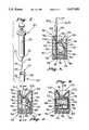
- FIG. 1is an exploded view of a preferred exemplary embodiment of the present invention, a surgical instrument sharp end foil, showing a housing, a gripping element, a biasing element and a sealing element.
- FIG. 2is a perspective view of the surgical sharp end foil of FIG. 1, positioned to receive the free end of a syringe needle through a funnel-shaped sharps guide;
- FIG. 3is a side section of the surgical sharp end foil of FIG. 1, showing the housing, the gripping element, the biasing element, and the sealing element in assembled relation.
- FIG. 4is a front section of the surgical sharp end taken through line 4--4 of FIG. 3.
- FIG. 5is the side section of the surgical sharp end foil of FIG. 3 after the free end of a syringe needle has been inserted therein;
- FIG. 6is a partial section of the surgical sharp end foil of FIG. 5 showing a preferred gripping element in engagement with an inserted syringe needle after attempted withdrawal of the syringe needle.
- the preferred exemplary embodimentis a surgical instruments sharp end foil configured to receive and permanently cap the free end of a typical syringe needle.
- Syringe needle assembly 20includes a syringe needle 22 having a free end 24 , a restrained end 25, an outer surface 26, and a longitudinal axis 27. Free end 24 is provided with a sharp tip 28 to facilitate invasive procedures.
- Syringe needle 22typically is made of stainless steel and has an annular cross-section which defines a cylindrical cavity extending along longitudinal axis 27. It will be understood by those skilled in the art that syringe needle 22, as described, does not form a part of the present invention.
- the preferred foil 10includes a housing 30, a gripping element 70, a biasing element 80 and a sealing element 90.
- Housing 30is provided in the form of a two-part plastic assembly composed of a first section 32 and a second section 34. Housing 30 includes first and second substantially opposed ends 36 and 38. A sharps receiving portion 100 is provided at first end 36.
- housing 30is also provided with a first set of substantially opposed lateral interior surfaces 40 and 42, an upper interior surface 44 and lower interior surface 46. As best shown in FIG. 4, housing 30 also includes a second set of substantially opposed lateral interior surfaces hereinafter referred to as interior sidewalls 48 and 50. Lateral interior surfaces 40 and 42 and interior sidewalls 48 and 50 each extend between upper and lower interior surfaces 44 and 46 to define interior cavity 60. Gripping element 70, biasing element 80 and sealing element 90 are provided therein.
- Lateral interior surface 40includes upper planar portion 52 and lower portion 54. As best shown in FIG. 5, upper planar portion 52 is configured to engage outer surface 26 of free end 24 along tangent 26A upon insertion of free end 24 into the foil 10. Lower portion 54 is configured to define a recess 62. Recess 62 is provided to facilitate the positioning of sealing element 90 adjacent lower interior surface 46 in a manner which ensures that, upon insertion of free end 24 into foil 10, tip 28 is fully ensconced with sealing element 90.
- Lateral interior surface 42includes an upper angled portion 56 and a lower planar portion 58.
- Upper angled portion 56 together with upper planar portion 52comprise a wedging element 64 which is configured to communicate with gripping element 70 before and after insertion of free end 24 into foil 10.
- upper angled portion 56inclines towards lateral interior surface 40 as upper angled portion 56 extends from lower planar portion 58 towards first end 36 to define an area of convergence or a wedge zone 66.
- Lower planar portion 58is substantially parallel to upper planar portion 52.
- Gripping element 70is substantially cylindrical in shape, having two flat ends 72 and 74 and a substantially arcuate gripping surface 76 extending therebetween. As can be seen in FIG. 4, gripping element 70 is positioned within interior cavity 60 such flat ends 72 and 74 are adjacent interior sidewalls 48 and 50. The distance between sidewalls 72 and 74 is sufficient to permit gripping element 70 to slidably move within cavity 60 between upper and lower interior surfaces 44 and 46. Referring now to FIGS.
- gripping surface 76(vis-a-vis wedging element 64 and free end 24) are selected to ensure that gripping surface 76 (in response to the biasing action of biasing element 80) remains in simultaneous engagement with upper planar portion 52 and angled portion 56 before insertion of free end 24 into housing 30 and to ensure that gripping surface 76 (in response to the biasing action of biasing element 80) remains in simultaneous engagement with the outer surface 26 of free end 24 along tangent 26B and angled portion 56 after insertion of free end 24 into housing 30.
- substantially arcuate gripping surface 76facilitates the foregoing described purposes while at the same time ensuring that gripping element 70 does not engage free end 24 in such a manner as to prevent free end 24 from being fully inserted into the interior cavity 60 as best shown in FIG. 5. It will be understood by those skilled in the art that other configurations of gripping element 70 may also facilitate these purposes.
- biasing element 80is composed of an annular shaped elastomer, having two ends 82 and 84, a substantially arcuate outer surface 86, and radial cavity 88 extending between ends 82 and 84. As best shown in FIG. 4, biasing element 80 is positioned within the interior cavity 60, between the gripping element 70 and sealing element 90, such that ends 82 and 84 are adjacent sidewalls 48 and 50 and outer surface 86 engages gripping element 70.
- biasing element 80is sufficiently large to ensure that biasing element 80 constantly acts upon gripping element 70, urging gripping element 70 towards first end 36 such that the gripping surface 76 engages the upper planar portion 52 and angled portion 56 as described above.
- first and second sections 32 and 34 of housing 30are joined together using conventional means.
- biasing element 80exerts an upward force on gripping element 70 at the interface between gripping element 70 and biasing element 80. This upward force drives gripping element 70 into engagement with upper planar portion 52 and angled portion 56, effectively wedging gripping element 70 therebetween.
- the pressure exerted against gripping element 70 at the interface between gripping element 70 and angled portion 56includes a component of force which is perpendicular to upper planar portion 52. This component of force is offset by an opposing force at the interface between gripping element 70 and upper planar portion 52.
- free end 24is wedged between upper planar portion 52 and gripping element 70 thereby displacing gripping element 70 and causing gripping element 70 to move downward towards second end 38.
- free end 24is engaged by upper planar portion 52 along tangent 26A and engaged by gripping element 70 along tangent 26B.
- the downward motion of gripping element 70causes biasing element 80 to further compress thereby increasing the amount of pressure exerted by biasing element 80 against gripping element 70 at the interface between gripping element 70 and biasing element 80.
- any attempt to withdraw needle 22 from interior cavity 60 after insertionwill generate opposing frictional forces at the interface between upper planar portion 52 and free end 24 and at the interface between gripping element 70 and free end 24.
- the frictional force exerted by free end 24 upon gripping element 70will tend to drive gripping element 70 upward towards first end 36 thereby increasing the pressure exerted against the gripping element 70 at the interface between the gripping element 70 and the angled portion 56 which, in turn, will increase the pressure exerted both at the interface between upper planar portion 52 and free end 24 along tangent 26A and at the interface between gripping element 70 and free end 24 along tangent 26B, thereby increasing the needle retaining effect of foil 10.
- the greater the force applied to needle 22 tending to withdraw free end 24 from interior cavity 60the greater the frictional forces exerted upon free end 24 resisting such movement.
- Biasing element 80is selected to ensure that a chosen surgical sharp may be manually inserted into interior cavity 60 without difficulty while at the same time ensuring that any attempt to withdraw such sharp will be opposed by sufficient frictional forces as described above. While, in the preferred exemplary embodiment, biasing element 80 must be sufficiently large to render foil 10 operable, biasing element 80 must not be so large as to prevent needle 22 from being inserted into interior cavity sufficiently to ensure that tip 28 fully engages sealing element 90. Preferably, then, outer diameter 87 (compressed) of biasing element 80 as measured in a plane transverse to upper planar portion 52 must be less than the distance between the tangent 26B to outer surface 26 and lower planar portion 54.
- biasing element 80may be positioned with interior cavity 60 vis-a-vis gripping element 70 such that the pressure at the interface between gripping element 70 and biasing element 80 urges biasing element 80 away from upper planar portion 52 as best shown in FIG. 5.
- biasing element 80may be positioned with interior cavity 60 vis-a-vis gripping element 70 such that the pressure at the interface between gripping element 70 and biasing element 80 urges biasing element 80 away from upper planar portion 52 as best shown in FIG. 5.
- Teeth 78are provided substantially sharp edges 79 and are backwardly curving, as best shown in FIG. 6, to improve the gripping characteristics of gripping surface 76.
- Teeth 78 (and the rest of gripping element 70)are preferably composed of a material which is hard enough to gouge the outer surface 26 of free end 24 such that, upon application of a force tending to withdraw needle 22 from interior cavity 60, teeth 78 are driven into outer surface 26 thereby creating a mechanical interference which precludes manual withdrawal of needle 24.
- the free end 24 of needle 22is thus permanently engaged by foil 10. It will be understood by those skilled in the art that gripping surface 76 and upper planar portion 52 may, alternatively, be roughened or scored to improve the needle retaining effect of the present invention.
- sealing element 90is also provided with sealing element 90.
- sealing element 90is composed of a slab of material which is sufficiently soft to facilitate penetration of tip 28 into the sealing element 90 while at the same time ensuring a proper seal of the needle tip.
- sealing element 90is sized to complement lower interior surface 40 and to reside with recess 62. This placement of sealing element 90 ensures that, upon insertion of free end 24 into foil 10, tip 28 is fully ensconced with sealing element 90.
- housing 30is also provided with sharps receiving portion 100 at first end 36.
- sharps receiving portion 100includes sharps guide 102.
- Sharps guide 102defines a funnel-shaped recess having a maximum diameter 104 at first end 36 and a minimum diameter 106 between first and second ends 36 and 38.
- the minimum diameter 106defines an eccentric needle port 108 which is sized to receive the free end 24 of syringe needle 22.
- Needle port 108is positioned such that upper planar surface 52 is tangent to the outer diameter of needle port 108. This configuration enables the operator of syringe assemble 20 to place free end 24 through needle port 108 without difficulty while simultaneously ensuring that free end 24 will be properly positioned within the interior cavity 60 between upper planar portion 52 and gripping element 70.
- a plurality of foils 10will be mounted in an array on a flat bottom foil container which can be placed on a surgical table or other appropriate surface.
- the second end 38 of each foil 10may be attached to the foil container, using any suitable means, so that the sharps receiving portion 100 of each foil 10 is directed substantially upward.
- the containermay be provided with means to present the sharps receiving portions 100 at an angle to the horizontal to facilitate operability.
- the bottom of the containermay be provided with an adhesive or other suitable means to ensure against unwanted movement during use.
- wedging meansbiasing means and gripping means may be employed to generate compressive forces on the longitudinal surface of a surgical sharp which will increase in response to a longitudinal movement tending to withdraw the chosen sharp from the housing. Accordingly, the scope of the present invention is not limited to the specific embodiment as illustrated herein, but is limited only by the following claims and equivalents thereof.
Landscapes
- Health & Medical Sciences (AREA)
- Engineering & Computer Science (AREA)
- Life Sciences & Earth Sciences (AREA)
- Anesthesiology (AREA)
- General Health & Medical Sciences (AREA)
- Biomedical Technology (AREA)
- Heart & Thoracic Surgery (AREA)
- Hematology (AREA)
- Veterinary Medicine (AREA)
- Animal Behavior & Ethology (AREA)
- Public Health (AREA)
- Vascular Medicine (AREA)
- Environmental & Geological Engineering (AREA)
- Biophysics (AREA)
- Pulmonology (AREA)
- Infusion, Injection, And Reservoir Apparatuses (AREA)
- Materials For Medical Uses (AREA)
- Control Of Positive-Displacement Air Blowers (AREA)
Abstract
Description
Claims (17)
Priority Applications (12)
| Application Number | Priority Date | Filing Date | Title |
|---|---|---|---|
| US08/094,842US5417659A (en) | 1993-07-20 | 1993-07-20 | Surgical instrument sharp end foil |
| US08/275,258US5395338A (en) | 1993-07-20 | 1994-07-15 | Surgical instrument sharp end foil |
| PCT/US1994/008164WO1995003076A1 (en) | 1993-07-20 | 1994-07-20 | Surgical instrument sharp end foil |
| AU74007/94AAU7400794A (en) | 1993-07-20 | 1994-07-20 | Surgical instrument sharp end foil |
| CN94192817ACN1127467A (en) | 1993-07-20 | 1994-07-20 | Surgical instrument sharp end foil |
| CA002167720ACA2167720A1 (en) | 1993-07-20 | 1994-07-20 | Surgical instrument sharp end foil |
| JP7505282AJPH09500307A (en) | 1993-07-20 | 1994-07-20 | Sharp edged foil for surgical instruments |
| EP94923979AEP0710128A4 (en) | 1993-07-20 | 1994-07-20 | Surgical instrument sharp end foil |
| US08/376,399US5533974A (en) | 1993-07-20 | 1995-01-23 | Locking safety cover for sharp instruments |
| US08/472,553US5584809A (en) | 1993-07-20 | 1995-06-07 | Safety catheter |
| US08/583,989US5601532A (en) | 1993-07-20 | 1996-01-11 | Locking safety cover for sharp instruments |
| US08/587,716US5697907A (en) | 1993-07-20 | 1996-01-19 | Safety catheter |
Applications Claiming Priority (1)
| Application Number | Priority Date | Filing Date | Title |
|---|---|---|---|
| US08/094,842US5417659A (en) | 1993-07-20 | 1993-07-20 | Surgical instrument sharp end foil |
Related Child Applications (2)
| Application Number | Title | Priority Date | Filing Date |
|---|---|---|---|
| US08/275,258ContinuationUS5395338A (en) | 1993-07-20 | 1994-07-15 | Surgical instrument sharp end foil |
| US08/376,399Continuation-In-PartUS5533974A (en) | 1993-07-20 | 1995-01-23 | Locking safety cover for sharp instruments |
Publications (1)
| Publication Number | Publication Date |
|---|---|
| US5417659Atrue US5417659A (en) | 1995-05-23 |
Family
ID=22247496
Family Applications (3)
| Application Number | Title | Priority Date | Filing Date |
|---|---|---|---|
| US08/094,842Expired - LifetimeUS5417659A (en) | 1993-07-20 | 1993-07-20 | Surgical instrument sharp end foil |
| US08/275,258Expired - LifetimeUS5395338A (en) | 1993-07-20 | 1994-07-15 | Surgical instrument sharp end foil |
| US08/376,399Expired - LifetimeUS5533974A (en) | 1993-07-20 | 1995-01-23 | Locking safety cover for sharp instruments |
Family Applications After (2)
| Application Number | Title | Priority Date | Filing Date |
|---|---|---|---|
| US08/275,258Expired - LifetimeUS5395338A (en) | 1993-07-20 | 1994-07-15 | Surgical instrument sharp end foil |
| US08/376,399Expired - LifetimeUS5533974A (en) | 1993-07-20 | 1995-01-23 | Locking safety cover for sharp instruments |
Country Status (7)
| Country | Link |
|---|---|
| US (3) | US5417659A (en) |
| EP (1) | EP0710128A4 (en) |
| JP (1) | JPH09500307A (en) |
| CN (1) | CN1127467A (en) |
| AU (1) | AU7400794A (en) |
| CA (1) | CA2167720A1 (en) |
| WO (1) | WO1995003076A1 (en) |
Cited By (53)
| Publication number | Priority date | Publication date | Assignee | Title |
|---|---|---|---|---|
| US5584809A (en)* | 1993-07-20 | 1996-12-17 | Graphic Controls Corporation | Safety catheter |
| US5601532A (en)* | 1993-07-20 | 1997-02-11 | Graphic Controls Corporation | Locking safety cover for sharp instruments |
| US5697907A (en)* | 1993-07-20 | 1997-12-16 | Graphic Controls Corporation | Safety catheter |
| US6036671A (en)* | 1997-07-17 | 2000-03-14 | Frey; William J. | Breakaway syringe and disposal apparatus |
| US6123193A (en)* | 1999-10-07 | 2000-09-26 | Arrow International, Inc. | Sharps container |
| WO2001070595A1 (en) | 2000-03-21 | 2001-09-27 | Atrion Medical Products, Inc. | Surgical needle immobilization device |
| US20030100868A1 (en)* | 2001-03-15 | 2003-05-29 | Ferguson F. Mark | Safety shield for medical needles |
| US6605064B2 (en) | 2000-09-15 | 2003-08-12 | Thomas Hatch | Single-use syringe |
| US20030195475A1 (en)* | 2001-03-15 | 2003-10-16 | Ferguson F. Mark | Safety shield for medical needles |
| US20030213713A1 (en)* | 2002-05-15 | 2003-11-20 | Future Top Medical Environment Technic Co., Ltd. | Needle extracting and recovering device |
| USD488799S1 (en) | 2003-06-26 | 2004-04-20 | Curtis L. Moore | Radio/alarm clock |
| US20040078003A1 (en)* | 2001-03-15 | 2004-04-22 | Smith Daniel K. | Resettable safety shield for medical needles |
| US20040092889A1 (en)* | 2002-11-07 | 2004-05-13 | Ferguson F. Mark | Safety shield for medical needles |
| US20040133167A1 (en)* | 2001-03-15 | 2004-07-08 | Ferguson F. Mark | Safety shield for medical needles |
| US20040171989A1 (en)* | 2001-03-15 | 2004-09-02 | Horner Shawn K. | Biopsy needle device |
| US6796962B2 (en) | 2001-03-15 | 2004-09-28 | Specialized Health Products, Inc. | Safety shield for medical needles |
| US20050043691A1 (en)* | 2001-03-15 | 2005-02-24 | Ferguson F. Mark | Safety shield for medical needles |
| USD502937S1 (en)* | 2004-03-26 | 2005-03-15 | Aspen Marketing, Inc. | Radio housing |
| US20050065820A1 (en)* | 2003-09-19 | 2005-03-24 | Mallett Scott R. | System and method for sorting medical waste for disposal |
| US20050096592A1 (en)* | 2003-10-31 | 2005-05-05 | James Carlyon | Safety shield |
| US20060102504A1 (en)* | 2004-11-15 | 2006-05-18 | Vu Phan | Sharps container, a process of manufacturing the sharps container, and a method of storing sharps in a container |
| US20070106231A1 (en)* | 2003-11-25 | 2007-05-10 | Snow Jeremy K | Resettable safety shield for medical needles |
| US7275645B2 (en) | 2003-09-19 | 2007-10-02 | Vesta Medical, Llc | Handheld medical waste sorting device |
| US7303081B2 (en) | 2003-09-19 | 2007-12-04 | Vesta Medical, Llc | Handheld medical waste sorting method |
| US7311207B2 (en) | 2003-09-19 | 2007-12-25 | Vesta Medical, Llc | System for sorting discarded and spent pharmaceutical items |
| US7318529B2 (en) | 2003-09-19 | 2008-01-15 | Vest Medical, Llc | Method for sorting discarded and spent pharmaceutical items |
| US20080021387A1 (en)* | 2005-08-31 | 2008-01-24 | Rodolfo Gaba | Medical Sharps Retardation Apparatus and a Method of Retarding Medical Sharps from Future Use |
| US20080065015A1 (en)* | 2004-11-01 | 2008-03-13 | Richard Fiser | Locking clip with trigger bushing |
| US20080197059A1 (en)* | 2003-09-19 | 2008-08-21 | Vesta Medical, Llc | Removable Liners for Waste Sorting System |
| US20090131870A1 (en)* | 2007-09-27 | 2009-05-21 | Fiser Richard L | I.v. catheter assembly and needle safety device |
| US7562025B2 (en) | 2003-09-19 | 2009-07-14 | Vesta Medical, Llc | Waste sorting system with query function, and method thereof |
| US7624864B1 (en) | 2005-04-08 | 2009-12-01 | Medvision, Inc. | Permanent sharps capture devices, systems and methods of use |
| US7648028B2 (en) | 2005-04-22 | 2010-01-19 | Becton, Dickinson And Company | Adapter for multiple capacity needle immobilizing device |
| US7654735B2 (en) | 2005-11-03 | 2010-02-02 | Covidien Ag | Electronic thermometer |
| US7731692B2 (en) | 2005-07-11 | 2010-06-08 | Covidien Ag | Device for shielding a sharp tip of a cannula and method of using the same |
| US7828773B2 (en) | 2005-07-11 | 2010-11-09 | Covidien Ag | Safety reset key and needle assembly |
| US7850650B2 (en) | 2005-07-11 | 2010-12-14 | Covidien Ag | Needle safety shield with reset |
| US7905857B2 (en) | 2005-07-11 | 2011-03-15 | Covidien Ag | Needle assembly including obturator with safety reset |
| US7970722B1 (en) | 1999-11-08 | 2011-06-28 | Aloft Media, Llc | System, method and computer program product for a collaborative decision platform |
| US8195328B2 (en) | 2003-09-19 | 2012-06-05 | Vesta Medical, Llc | Combination disposal and dispensing apparatus and method |
| US20120311839A1 (en)* | 2011-06-08 | 2012-12-13 | Becton, Dickinson And Company | Medical needle removal and storage device |
| US8348893B2 (en) | 2007-12-20 | 2013-01-08 | Covidien Lp | Locking clip assembly with spring-loaded collar |
| US8357104B2 (en) | 2007-11-01 | 2013-01-22 | Coviden Lp | Active stylet safety shield |
| US8486024B2 (en) | 2011-04-27 | 2013-07-16 | Covidien Lp | Safety IV catheter assemblies |
| US8628497B2 (en) | 2011-09-26 | 2014-01-14 | Covidien Lp | Safety catheter |
| US8715250B2 (en) | 2011-09-26 | 2014-05-06 | Covidien Lp | Safety catheter and needle assembly |
| US8834417B2 (en) | 2005-06-06 | 2014-09-16 | Covidien Ag | Needle assembly with removable depth stop |
| US8834422B2 (en) | 2011-10-14 | 2014-09-16 | Covidien Lp | Vascular access assembly and safety device |
| US8939938B2 (en) | 2006-10-12 | 2015-01-27 | Covidien Lp | Needle tip protector |
| US10321968B2 (en) | 2015-10-23 | 2019-06-18 | Medline Industries, Inc. | Sharps container |
| US10457578B1 (en) | 2018-06-22 | 2019-10-29 | Gary McInnis | Automated sulfur burner for agricultural irrigation |
| EP3644887B1 (en)* | 2017-06-30 | 2023-07-26 | Stryker Corporation | Waste disposal system and waste receiver for receiving and disposing of pharmaceutical waste material |
| US12064797B2 (en) | 2018-12-27 | 2024-08-20 | Stryker Corporation | Method of disposing of waste receiver, waste receiver for pharmaceutical waste and method of assembling the waste receiver |
Families Citing this family (87)
| Publication number | Priority date | Publication date | Assignee | Title |
|---|---|---|---|---|
| GB2292525B (en)* | 1994-08-24 | 1998-07-01 | Sterimatic Holdings Ltd | Catheter placement units |
| US5564565A (en)* | 1994-09-14 | 1996-10-15 | Yamada; Todd H. | Disposable hypodermic needle receptacle |
| NL1002199C2 (en)* | 1996-01-29 | 1997-07-30 | Cekumed B V | Protective cap for injection or infusion needle |
| US6013058A (en)* | 1996-06-12 | 2000-01-11 | Biolink Corporation | Device for subcutaneous accessibility |
| US5800395A (en)* | 1996-12-05 | 1998-09-01 | Mdc Investment Holdings, Inc. | Medical device with retractable needle |
| AU5370898A (en)* | 1996-12-05 | 1998-06-29 | Mdc Investment Holdings, Inc. | Fluid collection device with retractable needle |
| US6004278A (en)* | 1996-12-05 | 1999-12-21 | Mdc Investment Holdings, Inc. | Fluid collection device with retractable needle |
| USD526409S1 (en) | 1998-07-14 | 2006-08-08 | Unomedical A/S | Medical puncturing device |
| US6355021B1 (en) | 1998-07-14 | 2002-03-12 | Maersk Medical A/S | Medical puncturing device |
| GB0118078D0 (en)* | 2001-07-25 | 2001-09-19 | Kay George C | Intraosseous anaesthesia delivery system |
| US6830562B2 (en) | 2001-09-27 | 2004-12-14 | Unomedical A/S | Injector device for placing a subcutaneous infusion set |
| ITTO20011228A1 (en) | 2001-12-28 | 2003-06-28 | Cane Srl | DISPOSABLE NEEDLE CONTAINER. |
| DE60304681T2 (en) | 2002-02-12 | 2007-01-25 | Unomedical A/S | INFUSION DEVICE WITH NADELSCHUTZHÜLSE |
| US20040051019A1 (en)* | 2002-09-02 | 2004-03-18 | Mogensen Lasse Wesseltoft | Apparatus for and a method of adjusting the length of an infusion tube |
| AU2003258487A1 (en) | 2002-09-02 | 2004-03-19 | Unomedical A/S | A device for subcutaneous administration of a medicament to a patient |
| EP1534378B1 (en) | 2002-09-02 | 2008-12-31 | Unomedical A/S | A device for subcutaneous administration of a medicament to a patient and tubing for same |
| AU2003257754A1 (en) | 2002-09-02 | 2004-03-19 | Unomedical A/S | An apparatus and a method for adjustment of the length of an infusion tubing |
| DK200201823A (en) | 2002-11-26 | 2004-05-27 | Maersk Medical As | Connection piece for a hose connection |
| DE10333118B4 (en)* | 2002-11-29 | 2008-02-21 | Disetronic Licensing Ag | Puncture device for piercing a hypodermic needle |
| US20040158202A1 (en) | 2003-02-12 | 2004-08-12 | Soren Jensen | Cover |
| US7070580B2 (en) | 2003-04-01 | 2006-07-04 | Unomedical A/S | Infusion device and an adhesive sheet material and a release liner |
| WO2005009525A1 (en)* | 2003-07-21 | 2005-02-03 | Disetronic Licensing Ag | Insertion device for inserting an injection needle |
| US20050047957A1 (en)* | 2003-09-03 | 2005-03-03 | Donald Nevin | Autoclave sterilization method and apparatus |
| US8012144B2 (en)* | 2003-09-22 | 2011-09-06 | Boston Scientific Scimed, Inc. | Elongate medical device having an interference fit packaging member |
| USD576267S1 (en) | 2003-10-15 | 2008-09-02 | Unomedical A/S | Medical infusion device |
| USD579541S1 (en) | 2003-10-15 | 2008-10-28 | Unomedical A/S | Medical insertion device |
| USD554253S1 (en) | 2003-10-15 | 2007-10-30 | Unomedical A/S | Medical infusion device |
| US7494481B2 (en)* | 2004-12-03 | 2009-02-24 | Medtronic Minimed, Inc. | Multi-position infusion set device and process |
| US7513888B2 (en)* | 2004-02-17 | 2009-04-07 | Smiths Medical Asd, Inc. | Needle guards |
| MXPA06010784A (en) | 2004-03-26 | 2006-12-15 | Unomedical As | Injector device for infusion set. |
| US8062250B2 (en) | 2004-08-10 | 2011-11-22 | Unomedical A/S | Cannula device |
| US7867199B2 (en) | 2004-12-10 | 2011-01-11 | Unomedical A/S | Inserter |
| US20060213793A1 (en)* | 2005-03-08 | 2006-09-28 | Christopher Brand | Syringe needle protector |
| US8603039B2 (en) | 2005-03-08 | 2013-12-10 | Christopher Brand | Syringe protector |
| US7985199B2 (en) | 2005-03-17 | 2011-07-26 | Unomedical A/S | Gateway system |
| CA2612664A1 (en) | 2005-06-28 | 2007-01-04 | Unomedical A/S | Packing for infusion set and method of applying an infusion set |
| US7632243B2 (en) | 2005-08-08 | 2009-12-15 | Smiths Medical Asd, Inc. | Duckbill catheter release mechanism |
| US8162881B2 (en)* | 2005-08-08 | 2012-04-24 | Smiths Medical Asd, Inc. | Needle guard mechanism with angled strut wall |
| US8403886B2 (en)* | 2005-08-08 | 2013-03-26 | Smiths Medical Asd, Inc. | Needle guard clip with lip |
| US7753877B2 (en) | 2005-08-08 | 2010-07-13 | Smiths Medical Asd, Inc. | Needle guard strut wall clip |
| EP1762259B2 (en) | 2005-09-12 | 2025-01-01 | Unomedical A/S | Inserter for an infusion set with a first and second spring units |
| USD655807S1 (en) | 2005-12-09 | 2012-03-13 | Unomedical A/S | Medical device |
| DK1962926T3 (en) | 2005-12-23 | 2009-09-28 | Unomedical As | injection device |
| US7658725B2 (en)* | 2006-02-16 | 2010-02-09 | Smiths Medical Asd, Inc. | Enclosed needle device with duckbill release mechanism |
| WO2007098771A2 (en) | 2006-02-28 | 2007-09-07 | Unomedical A/S | Inserter for infusion part and infusion part provided with needle protector |
| CA2653631A1 (en) | 2006-06-07 | 2007-12-13 | Unomedical A/S | Inserter |
| CA2653764A1 (en) | 2006-06-09 | 2007-12-13 | Unomedical A/S | Mounting pad |
| JP2009545341A (en) | 2006-08-02 | 2009-12-24 | ウノメディカル アクティーゼルスカブ | Cannula and delivery device |
| EP1917990A1 (en) | 2006-10-31 | 2008-05-07 | Unomedical A/S | Infusion set |
| US9056188B2 (en)* | 2006-11-22 | 2015-06-16 | Becton, Dickinson And Company | Needle shielding flag structures |
| US9220871B2 (en)* | 2006-11-22 | 2015-12-29 | Becton, Dickinson And Company | Needle shielding pawl structures |
| US8057431B2 (en) | 2006-12-21 | 2011-11-15 | B. Braun Melsungen Ag | Hinged cap for needle device |
| EP2155311B1 (en) | 2007-06-20 | 2013-01-02 | Unomedical A/S | A method and an apparatus for making a catheter |
| AU2008270327A1 (en) | 2007-07-03 | 2009-01-08 | Unomedical A/S | Inserter having bistable equilibrium states |
| DE602008005153D1 (en) | 2007-07-10 | 2011-04-07 | Unomedical As | INSERT WITH TWO SPRINGS |
| AU2008277763B2 (en) | 2007-07-18 | 2011-11-10 | Unomedical A/S | Insertion device with pivoting action |
| US7713243B2 (en)* | 2007-09-25 | 2010-05-11 | Becton, Dickinson And Company | Tip shield for needle stick prevention |
| WO2009067646A1 (en) | 2007-11-21 | 2009-05-28 | Becton, Dickinson And Company | Needle safety device |
| MX2010005610A (en)* | 2007-11-21 | 2010-06-01 | Becton Dickinson Co | Safety needle guard. |
| US8858503B2 (en)* | 2007-12-21 | 2014-10-14 | Becton, Dickinson And Company | Tip shield with gripping surfaces and guard features |
| ATE522240T1 (en) | 2008-02-13 | 2011-09-15 | Unomedical As | SEAL BETWEEN A CANNULAR PART AND A FLUID PATH |
| US9566384B2 (en) | 2008-02-20 | 2017-02-14 | Unomedical A/S | Insertion device with horizontally moving part |
| AU2009331635A1 (en) | 2008-12-22 | 2011-06-23 | Unomedical A/S | Medical device comprising adhesive pad |
| AU2010277755A1 (en) | 2009-07-30 | 2012-02-02 | Unomedical A/S | Inserter device with horizontal moving part |
| KR20120047896A (en) | 2009-08-07 | 2012-05-14 | 우노메디컬 에이/에스 | Delivery device with sensor and one or more cannulas |
| KR20130018783A (en) | 2010-03-30 | 2013-02-25 | 우노메디컬 에이/에스 | Medical device |
| EP2433663A1 (en) | 2010-09-27 | 2012-03-28 | Unomedical A/S | Insertion system |
| EP2436412A1 (en) | 2010-10-04 | 2012-04-04 | Unomedical A/S | A sprinkler cannula |
| RU2584388C2 (en) | 2010-11-22 | 2016-05-20 | Б. Браун Мельзунген Аг | Hinged panel device and related methods |
| WO2013050277A1 (en) | 2011-10-05 | 2013-04-11 | Unomedical A/S | Inserter for simultaneous insertion of multiple transcutaneous parts |
| EP2583715A1 (en) | 2011-10-19 | 2013-04-24 | Unomedical A/S | Infusion tube system and method for manufacture |
| US9440051B2 (en) | 2011-10-27 | 2016-09-13 | Unomedical A/S | Inserter for a multiplicity of subcutaneous parts |
| US9555221B2 (en) | 2014-04-10 | 2017-01-31 | Smiths Medical Asd, Inc. | Constant force hold tip protector for a safety catheter |
| SG11201608547XA (en) | 2014-04-18 | 2016-11-29 | Becton Dickinson Co | Needle capture safety interlock for catheter |
| US11511052B2 (en) | 2014-11-10 | 2022-11-29 | Becton, Dickinson And Company | Safety IV catheter with V-clip interlock and needle tip capture |
| US10029049B2 (en) | 2015-03-19 | 2018-07-24 | B. Braun Melsungen Ag | Hinged shield assemblies and related methods |
| CN105030345B (en)* | 2015-07-21 | 2018-05-11 | 苏州百利医疗用品有限公司 | Medical needle protective device |
| WO2018075694A1 (en) | 2016-10-18 | 2018-04-26 | Piper Access, Llc | Intraosseous access devices, systems, and methods |
| JP7169982B2 (en) | 2017-03-07 | 2022-11-11 | パイパー・アクセス、エルエルシー | Safety shields for elongated instruments and related systems and methods |
| CA3050963A1 (en) | 2017-03-10 | 2018-09-13 | Piper Access, Llc. | Securement devices, systems, and methods |
| CN107981921B (en)* | 2017-12-29 | 2025-02-28 | 上海联影医疗科技股份有限公司 | Puncture positioning system and needle holding device |
| ES2953372T3 (en) | 2018-02-20 | 2023-11-10 | Piper Access Llc | Drilling devices and related methods |
| US12121709B1 (en) | 2019-03-22 | 2024-10-22 | Christopher Brand | Adaptable multiprocedural sharps safety device |
| CA3169051A1 (en) | 2019-09-10 | 2021-03-18 | Medsource International Llc | An intravenous catheter device |
| CN112546357B (en)* | 2020-12-31 | 2021-06-04 | 四川大学华西医院 | Device for disposal of waste medical sharps envelopes |
| US12337123B2 (en) | 2021-05-06 | 2025-06-24 | Medsource Labs, Llc | Safety intravenous cannula |
| US12186497B2 (en) | 2022-01-14 | 2025-01-07 | Medsource International Llc | Intravenous cannula |
Citations (9)
| Publication number | Priority date | Publication date | Assignee | Title |
|---|---|---|---|---|
| US4013109A (en)* | 1975-08-22 | 1977-03-22 | Dan Sandel | Disposable container for surgical instruments |
| US4728321A (en)* | 1987-04-16 | 1988-03-01 | Ming-Chiu Wu | Syringe cap with adhesive holding plug |
| US4842138A (en)* | 1986-03-10 | 1989-06-27 | Devon Industries, Inc. | Rigid disposable container for holding and dispensing of used medical sharps and other medical-surgical materials |
| US4986811A (en)* | 1988-09-23 | 1991-01-22 | Post Medical, Inc. | Apparatus and method for safely removing needles from syringes |
| US4995871A (en)* | 1988-02-04 | 1991-02-26 | Snow Brand Milk Products Co., Ltd. | Needle detacher for syringe |
| US5024326A (en)* | 1989-05-24 | 1991-06-18 | Devon Industries, Inc. | Medical instrument holder and sharps disposal container |
| US5067949A (en)* | 1990-04-23 | 1991-11-26 | Freundlich Lawrence F | Instrument for unsheathing, resheathing and disposing of a medical syringe needle |
| US5187850A (en)* | 1987-04-22 | 1993-02-23 | Mccammon John W | Needle disposal system |
| US5195983A (en)* | 1991-08-27 | 1993-03-23 | Penta Associates | Syringe guard and disposal system |
Family Cites Families (5)
| Publication number | Priority date | Publication date | Assignee | Title |
|---|---|---|---|---|
| CA1270716A (en)* | 1987-09-18 | 1990-06-26 | Graham Maitland Willoughby | Device for removing needles or needle/sheath combination from hypodermic syringes |
| USRE34416E (en)* | 1988-07-11 | 1993-10-19 | Critikon, Inc. | I.V. catheter with self-locating needle guard |
| ES2081973T3 (en)* | 1989-02-01 | 1996-03-16 | Sero Guard Corp | AUTOMATIC DISPOSABLE HYPODERMIC NEEDLE PROTECTOR. |
| US5279581A (en)* | 1990-05-09 | 1994-01-18 | Firth John R | Disposable self-shielding hypodermic syringe |
| US5334158A (en)* | 1993-12-20 | 1994-08-02 | Mclees Donald J | Automatic needle tip guard for standard hypodermic needles |
- 1993
- 1993-07-20USUS08/094,842patent/US5417659A/ennot_activeExpired - Lifetime
- 1994
- 1994-07-15USUS08/275,258patent/US5395338A/ennot_activeExpired - Lifetime
- 1994-07-20CACA002167720Apatent/CA2167720A1/ennot_activeAbandoned
- 1994-07-20CNCN94192817Apatent/CN1127467A/enactivePending
- 1994-07-20EPEP94923979Apatent/EP0710128A4/ennot_activeWithdrawn
- 1994-07-20AUAU74007/94Apatent/AU7400794A/ennot_activeAbandoned
- 1994-07-20JPJP7505282Apatent/JPH09500307A/enactivePending
- 1994-07-20WOPCT/US1994/008164patent/WO1995003076A1/ennot_activeApplication Discontinuation
- 1995
- 1995-01-23USUS08/376,399patent/US5533974A/ennot_activeExpired - Lifetime
Patent Citations (11)
| Publication number | Priority date | Publication date | Assignee | Title |
|---|---|---|---|---|
| US4013109A (en)* | 1975-08-22 | 1977-03-22 | Dan Sandel | Disposable container for surgical instruments |
| US4013109B1 (en)* | 1975-08-22 | 1995-04-25 | Dan Sandel | Disposable container for surgical instruments. |
| US4842138A (en)* | 1986-03-10 | 1989-06-27 | Devon Industries, Inc. | Rigid disposable container for holding and dispensing of used medical sharps and other medical-surgical materials |
| US4842138B1 (en)* | 1986-03-10 | 1992-01-28 | Devon Ind Inc | |
| US4728321A (en)* | 1987-04-16 | 1988-03-01 | Ming-Chiu Wu | Syringe cap with adhesive holding plug |
| US5187850A (en)* | 1987-04-22 | 1993-02-23 | Mccammon John W | Needle disposal system |
| US4995871A (en)* | 1988-02-04 | 1991-02-26 | Snow Brand Milk Products Co., Ltd. | Needle detacher for syringe |
| US4986811A (en)* | 1988-09-23 | 1991-01-22 | Post Medical, Inc. | Apparatus and method for safely removing needles from syringes |
| US5024326A (en)* | 1989-05-24 | 1991-06-18 | Devon Industries, Inc. | Medical instrument holder and sharps disposal container |
| US5067949A (en)* | 1990-04-23 | 1991-11-26 | Freundlich Lawrence F | Instrument for unsheathing, resheathing and disposing of a medical syringe needle |
| US5195983A (en)* | 1991-08-27 | 1993-03-23 | Penta Associates | Syringe guard and disposal system |
Cited By (132)
| Publication number | Priority date | Publication date | Assignee | Title |
|---|---|---|---|---|
| US5584809A (en)* | 1993-07-20 | 1996-12-17 | Graphic Controls Corporation | Safety catheter |
| US5601532A (en)* | 1993-07-20 | 1997-02-11 | Graphic Controls Corporation | Locking safety cover for sharp instruments |
| US5697907A (en)* | 1993-07-20 | 1997-12-16 | Graphic Controls Corporation | Safety catheter |
| US6036671A (en)* | 1997-07-17 | 2000-03-14 | Frey; William J. | Breakaway syringe and disposal apparatus |
| US6123193A (en)* | 1999-10-07 | 2000-09-26 | Arrow International, Inc. | Sharps container |
| US6276527B1 (en)* | 1999-10-07 | 2001-08-21 | Arrow International, Inc. | Sharps container |
| US8160988B1 (en) | 1999-11-08 | 2012-04-17 | Aloft Media, Llc | System, method and computer program product for a collaborative decision platform |
| US8005777B1 (en) | 1999-11-08 | 2011-08-23 | Aloft Media, Llc | System, method and computer program product for a collaborative decision platform |
| US7970722B1 (en) | 1999-11-08 | 2011-06-28 | Aloft Media, Llc | System, method and computer program product for a collaborative decision platform |
| WO2001070595A1 (en) | 2000-03-21 | 2001-09-27 | Atrion Medical Products, Inc. | Surgical needle immobilization device |
| EP1265796B1 (en)* | 2000-03-21 | 2009-09-09 | Atrion Medical Products, Inc. | Surgical needle immobilization device |
| US6382417B2 (en) | 2000-03-21 | 2002-05-07 | Atrion Medical Products, Inc. | Surgical needle immobilization device |
| US6605064B2 (en) | 2000-09-15 | 2003-08-12 | Thomas Hatch | Single-use syringe |
| US6645180B1 (en) | 2000-09-15 | 2003-11-11 | Thomas Hatch | Single-use syringe |
| US20040236289A1 (en)* | 2001-03-15 | 2004-11-25 | Ferguson F. Mark | Safety shield for medical needles |
| US7618395B2 (en) | 2001-03-15 | 2009-11-17 | Specialized Health Products, Inc. | Methods for shielding medical needles |
| US7357784B2 (en) | 2001-03-15 | 2008-04-15 | Specialized Health Products Inc. | Safety shield for medical needles |
| US20040133167A1 (en)* | 2001-03-15 | 2004-07-08 | Ferguson F. Mark | Safety shield for medical needles |
| US20040171989A1 (en)* | 2001-03-15 | 2004-09-02 | Horner Shawn K. | Biopsy needle device |
| US6796962B2 (en) | 2001-03-15 | 2004-09-28 | Specialized Health Products, Inc. | Safety shield for medical needles |
| US7341573B2 (en) | 2001-03-15 | 2008-03-11 | Specialized Health Products Inc. | Safety shield for medical needles |
| US20050043691A1 (en)* | 2001-03-15 | 2005-02-24 | Ferguson F. Mark | Safety shield for medical needles |
| US9539398B2 (en) | 2001-03-15 | 2017-01-10 | Specialized Health Products, Inc. | Safety shield for medical needles |
| US20050059937A1 (en)* | 2001-03-15 | 2005-03-17 | Ferguson F. Mark | Safety shield for medical needles |
| US8845584B2 (en) | 2001-03-15 | 2014-09-30 | Specialized Health Products, Inc. | Safety shield for medical needles |
| US20050070855A1 (en)* | 2001-03-15 | 2005-03-31 | Ferguson F Mark | Safety shield for medical needles |
| US20040078003A1 (en)* | 2001-03-15 | 2004-04-22 | Smith Daniel K. | Resettable safety shield for medical needles |
| US7413562B2 (en) | 2001-03-15 | 2008-08-19 | Specialized Health Products, Inc. | Safety shield for medical needles |
| US7179244B2 (en) | 2001-03-15 | 2007-02-20 | Specialized Health Products, Inc. | Resettable safety shield for medical needles |
| US6902546B2 (en) | 2001-03-15 | 2005-06-07 | Specialized Health Products, Inc. | Safety shield for medical needles |
| US6984213B2 (en) | 2001-03-15 | 2006-01-10 | Specialized Health Products, Inc. | Biopsy needle device |
| US7004927B2 (en) | 2001-03-15 | 2006-02-28 | Specialized Health Products, Inc. | Safety shield for medical needles |
| US7008402B2 (en) | 2001-03-15 | 2006-03-07 | Specialized Health Products, Inc. | Safety shield for medical needles |
| US20030100868A1 (en)* | 2001-03-15 | 2003-05-29 | Ferguson F. Mark | Safety shield for medical needles |
| US20030195475A1 (en)* | 2001-03-15 | 2003-10-16 | Ferguson F. Mark | Safety shield for medical needles |
| US7611485B2 (en) | 2001-03-15 | 2009-11-03 | C. R. Bard, Inc. | Safety shield for medical needles |
| US20030213713A1 (en)* | 2002-05-15 | 2003-11-20 | Future Top Medical Environment Technic Co., Ltd. | Needle extracting and recovering device |
| US6745898B2 (en)* | 2002-05-15 | 2004-06-08 | Future Top Medical Environment Technic Co., Ltd. | Needle extracting and recovering device |
| US20040092889A1 (en)* | 2002-11-07 | 2004-05-13 | Ferguson F. Mark | Safety shield for medical needles |
| US7458954B2 (en) | 2002-11-07 | 2008-12-02 | Specialized Health Products, Inc. | Safety shield for medical needles |
| USD488799S1 (en) | 2003-06-26 | 2004-04-20 | Curtis L. Moore | Radio/alarm clock |
| US7119689B2 (en) | 2003-09-19 | 2006-10-10 | Vesta Medical, Llc | System and method for sorting medical waste for disposal |
| US7483837B2 (en) | 2003-09-19 | 2009-01-27 | Vesta Medical, Llc | Waste sensing system |
| US7303080B2 (en) | 2003-09-19 | 2007-12-04 | Vesta Medical, Llc | Waste sensor for a disposable container |
| US7303081B2 (en) | 2003-09-19 | 2007-12-04 | Vesta Medical, Llc | Handheld medical waste sorting method |
| US7303082B2 (en) | 2003-09-19 | 2007-12-04 | Vesta Medical, Llc | Medical waste sorting system with container identification |
| US7311207B2 (en) | 2003-09-19 | 2007-12-25 | Vesta Medical, Llc | System for sorting discarded and spent pharmaceutical items |
| US7318529B2 (en) | 2003-09-19 | 2008-01-15 | Vest Medical, Llc | Method for sorting discarded and spent pharmaceutical items |
| US20050119933A1 (en)* | 2003-09-19 | 2005-06-02 | Mallett Scott R. | Waste container identification system |
| US7341147B2 (en) | 2003-09-19 | 2008-03-11 | Vesta Medical, Llc | Disposable container for use in a waste sorting system |
| US7275645B2 (en) | 2003-09-19 | 2007-10-02 | Vesta Medical, Llc | Handheld medical waste sorting device |
| US20050115874A1 (en)* | 2003-09-19 | 2005-06-02 | Mallett Scott R. | System for sorting waste |
| US7296688B2 (en) | 2003-09-19 | 2007-11-20 | Vesta Medical, Llc | Apparatus for facilitating medical waste disposal |
| US7383195B2 (en) | 2003-09-19 | 2008-06-03 | Vesta Medical, Llc | Methods of sorting waste |
| US8195328B2 (en) | 2003-09-19 | 2012-06-05 | Vesta Medical, Llc | Combination disposal and dispensing apparatus and method |
| US20080197059A1 (en)* | 2003-09-19 | 2008-08-21 | Vesta Medical, Llc | Removable Liners for Waste Sorting System |
| US7454358B2 (en) | 2003-09-19 | 2008-11-18 | Vesta Medical, Llc | Waste scanning method |
| US7138918B2 (en) | 2003-09-19 | 2006-11-21 | Vesta Medical, Llc | System for sorting waste |
| US20100213250A1 (en)* | 2003-09-19 | 2010-08-26 | Vesta Medical, Llc | Systems for identifying and categorizing medical waste |
| US7487100B2 (en) | 2003-09-19 | 2009-02-03 | Vesta Medical, Llc | Method of sorting regulated drug waste |
| US7533029B2 (en) | 2003-09-19 | 2009-05-12 | Vesta Medical, Llc | Waste sorting system for rendering drugs non-recoverable |
| US7533028B2 (en) | 2003-09-19 | 2009-05-12 | Vesta Medical, Llc | Waste sorting method for rendering drugs non-recoverable |
| US8868434B2 (en) | 2003-09-19 | 2014-10-21 | Carefusion 303, Inc. | Waste sorting and disposal method using labels |
| US7562025B2 (en) | 2003-09-19 | 2009-07-14 | Vesta Medical, Llc | Waste sorting system with query function, and method thereof |
| US7565299B2 (en) | 2003-09-19 | 2009-07-21 | Vesta Medical, Llc | Waste sorting and tracking system and method |
| US7126480B2 (en) | 2003-09-19 | 2006-10-24 | Vesta Medical, Llc | Waste sorting network |
| US7123150B2 (en) | 2003-09-19 | 2006-10-17 | Vesta Medical, Llc | Waste container identification system |
| US7617113B2 (en) | 2003-09-19 | 2009-11-10 | Vesta Medical, Llc | Medical waste sorting method |
| US7620559B2 (en) | 2003-09-19 | 2009-11-17 | Vesta Medical, Llc | System for facilitating medical waste disposal |
| US20050065820A1 (en)* | 2003-09-19 | 2005-03-24 | Mallett Scott R. | System and method for sorting medical waste for disposal |
| US8595021B2 (en) | 2003-09-19 | 2013-11-26 | Carefusion 303, Inc. | Methods for identifying and categorizing medical waste |
| US8560460B2 (en) | 2003-09-19 | 2013-10-15 | Carefusion 303, Inc. | Automated waste sorting system |
| US8204620B2 (en) | 2003-09-19 | 2012-06-19 | Vesta Medical, Llc | Method for combined disposal and dispensing of medical items |
| US7660724B2 (en) | 2003-09-19 | 2010-02-09 | Vesta Medical, Llc | Waste sorting system utilizing removable liners |
| US7664656B2 (en) | 2003-09-19 | 2010-02-16 | Mallett Scott R | Method of sorting waste utilizing removable liners |
| US8355994B2 (en) | 2003-09-19 | 2013-01-15 | Vesta Medical Llc | Sorting system for composite drugs |
| US8296243B2 (en) | 2003-09-19 | 2012-10-23 | Vesta Medical, Llc | Systems for identifying and categorizing medical waste |
| US7226434B2 (en) | 2003-10-31 | 2007-06-05 | Tyco Healthcare Group Lp | Safety shield |
| US7736332B2 (en) | 2003-10-31 | 2010-06-15 | Tyco Healthcare Group Lp | Safety shield |
| US8506528B2 (en) | 2003-10-31 | 2013-08-13 | Covidien Lp | Locking clip with trigger bushing |
| US20050096592A1 (en)* | 2003-10-31 | 2005-05-05 | James Carlyon | Safety shield |
| US9089673B2 (en) | 2003-10-31 | 2015-07-28 | Covidien Lp | Locking clip with trigger bushing |
| US20070106231A1 (en)* | 2003-11-25 | 2007-05-10 | Snow Jeremy K | Resettable safety shield for medical needles |
| US8096973B2 (en) | 2003-11-25 | 2012-01-17 | Specialized Health Products, Inc. | Resettable safety shield for medical needles |
| USD502937S1 (en)* | 2004-03-26 | 2005-03-15 | Aspen Marketing, Inc. | Radio housing |
| US7988664B2 (en) | 2004-11-01 | 2011-08-02 | Tyco Healthcare Group Lp | Locking clip with trigger bushing |
| US20080065015A1 (en)* | 2004-11-01 | 2008-03-13 | Richard Fiser | Locking clip with trigger bushing |
| US10195365B2 (en) | 2004-11-15 | 2019-02-05 | Becton, Dickinson And Company | Sharps container |
| US20060102504A1 (en)* | 2004-11-15 | 2006-05-18 | Vu Phan | Sharps container, a process of manufacturing the sharps container, and a method of storing sharps in a container |
| US10029050B2 (en) | 2004-11-15 | 2018-07-24 | Becton, Dickinson And Company | Process of manufacturing a sharps container, and a method of storing sharps in a container |
| US8522974B2 (en)* | 2004-11-15 | 2013-09-03 | Becton, Dickinson And Company | Sharps container |
| US7624864B1 (en) | 2005-04-08 | 2009-12-01 | Medvision, Inc. | Permanent sharps capture devices, systems and methods of use |
| US7648028B2 (en) | 2005-04-22 | 2010-01-19 | Becton, Dickinson And Company | Adapter for multiple capacity needle immobilizing device |
| US8834417B2 (en) | 2005-06-06 | 2014-09-16 | Covidien Ag | Needle assembly with removable depth stop |
| US7828773B2 (en) | 2005-07-11 | 2010-11-09 | Covidien Ag | Safety reset key and needle assembly |
| US7850650B2 (en) | 2005-07-11 | 2010-12-14 | Covidien Ag | Needle safety shield with reset |
| US8348894B2 (en) | 2005-07-11 | 2013-01-08 | Covidien Lp | Needle assembly including obturator with safety reset |
| US7976498B2 (en) | 2005-07-11 | 2011-07-12 | Tyco Healthcare Group Lp | Needle assembly including obturator with safety reset |
| US7731692B2 (en) | 2005-07-11 | 2010-06-08 | Covidien Ag | Device for shielding a sharp tip of a cannula and method of using the same |
| US8162889B2 (en) | 2005-07-11 | 2012-04-24 | Covidien Ag | Safety reset key and needle assembly |
| US8419687B2 (en) | 2005-07-11 | 2013-04-16 | Covidien Ag | Device for shielding a sharp tip of a cannula and method of using the same |
| US7905857B2 (en) | 2005-07-11 | 2011-03-15 | Covidien Ag | Needle assembly including obturator with safety reset |
| US8523809B2 (en) | 2005-07-11 | 2013-09-03 | Covidien Ag | Device for shielding a sharp tip of a cannula and method of using the same |
| US7984805B2 (en) | 2005-08-31 | 2011-07-26 | Griff Industries Inc | Medical sharps retardation apparatus and a method of retarding medical sharps from future use |
| US20080021387A1 (en)* | 2005-08-31 | 2008-01-24 | Rodolfo Gaba | Medical Sharps Retardation Apparatus and a Method of Retarding Medical Sharps from Future Use |
| US7654735B2 (en) | 2005-11-03 | 2010-02-02 | Covidien Ag | Electronic thermometer |
| US8939938B2 (en) | 2006-10-12 | 2015-01-27 | Covidien Lp | Needle tip protector |
| US8313469B2 (en) | 2007-09-27 | 2012-11-20 | Tyco Healthcare Group Lp | I.V. catheter assembly and needle safety device |
| US7963943B2 (en) | 2007-09-27 | 2011-06-21 | Tyco Healthcare Group Lp | I.V. catheter assembly and needle safety device |
| US20110224627A1 (en)* | 2007-09-27 | 2011-09-15 | Tyco Healthcare Group Lp | I.V. Catheter Assembly and Needle Safety Device |
| US20090131870A1 (en)* | 2007-09-27 | 2009-05-21 | Fiser Richard L | I.v. catheter assembly and needle safety device |
| US8357104B2 (en) | 2007-11-01 | 2013-01-22 | Coviden Lp | Active stylet safety shield |
| US8348893B2 (en) | 2007-12-20 | 2013-01-08 | Covidien Lp | Locking clip assembly with spring-loaded collar |
| US8486024B2 (en) | 2011-04-27 | 2013-07-16 | Covidien Lp | Safety IV catheter assemblies |
| US8926563B2 (en) | 2011-04-27 | 2015-01-06 | Covidien Lp | Safety IV catheter assemblies |
| US9579469B2 (en) | 2011-06-08 | 2017-02-28 | Becton, Dickinson And Company | Medical needle removal and storage device |
| US8829394B2 (en)* | 2011-06-08 | 2014-09-09 | Becton, Dickinson And Company | Medical needle removal and storage device |
| US9802006B2 (en) | 2011-06-08 | 2017-10-31 | Becton, Dickinson And Company | Medical needle removal and storage method |
| US20120311839A1 (en)* | 2011-06-08 | 2012-12-13 | Becton, Dickinson And Company | Medical needle removal and storage device |
| US10238811B2 (en) | 2011-06-08 | 2019-03-26 | Becton, Dickinson And Company | Medical needle removal and storage device |
| US9375552B2 (en) | 2011-09-26 | 2016-06-28 | Covidien Lp | Safety needle assembly |
| US8715250B2 (en) | 2011-09-26 | 2014-05-06 | Covidien Lp | Safety catheter and needle assembly |
| US8628497B2 (en) | 2011-09-26 | 2014-01-14 | Covidien Lp | Safety catheter |
| US8834422B2 (en) | 2011-10-14 | 2014-09-16 | Covidien Lp | Vascular access assembly and safety device |
| US10321968B2 (en) | 2015-10-23 | 2019-06-18 | Medline Industries, Inc. | Sharps container |
| US11559369B2 (en) | 2015-10-23 | 2023-01-24 | Medline Industries, Lp | Sharps container |
| US12082951B2 (en) | 2015-10-23 | 2024-09-10 | Medine Industries, LP | Sharps container |
| EP3644887B1 (en)* | 2017-06-30 | 2023-07-26 | Stryker Corporation | Waste disposal system and waste receiver for receiving and disposing of pharmaceutical waste material |
| US11845116B2 (en) | 2017-06-30 | 2023-12-19 | Stryker Corporation | Waste disposal system and waste receiver for receiving and disposing of pharmaceutical waste material |
| US10457578B1 (en) | 2018-06-22 | 2019-10-29 | Gary McInnis | Automated sulfur burner for agricultural irrigation |
| US12064797B2 (en) | 2018-12-27 | 2024-08-20 | Stryker Corporation | Method of disposing of waste receiver, waste receiver for pharmaceutical waste and method of assembling the waste receiver |
| US12318823B2 (en) | 2018-12-27 | 2025-06-03 | Stryker Corporation | Waste receiver for receiving a pharmaceutical waste material |
Also Published As
| Publication number | Publication date |
|---|---|
| EP0710128A1 (en) | 1996-05-08 |
| JPH09500307A (en) | 1997-01-14 |
| WO1995003076A1 (en) | 1995-02-02 |
| US5533974A (en) | 1996-07-09 |
| EP0710128A4 (en) | 1997-03-26 |
| CN1127467A (en) | 1996-07-24 |
| US5395338A (en) | 1995-03-07 |
| CA2167720A1 (en) | 1995-02-02 |
| AU7400794A (en) | 1995-02-20 |
Similar Documents
| Publication | Publication Date | Title |
|---|---|---|
| US5417659A (en) | Surgical instrument sharp end foil | |
| US4846809A (en) | Needle tip protective device | |
| US5584816A (en) | Hardpack shield for a pivoting needle guard | |
| US5601532A (en) | Locking safety cover for sharp instruments | |
| CN100528253C (en) | Safety shield for medical needles | |
| US4917243A (en) | Needle disposal device | |
| KR960010978B1 (en) | Lancet device | |
| US5143414A (en) | Medical device for holding hypodermic syringe needle caps | |
| KR100808768B1 (en) | Dental syringe | |
| JP4776664B2 (en) | Fluid collection device | |
| US20210153896A1 (en) | Device for Intraosseous Needle Removal | |
| IL132792A (en) | Disposable syringe needle attachment hub | |
| EP0170676A1 (en) | Syringe needle sheath and shield | |
| JP2002345955A (en) | Injection needle with safety cap | |
| EP1421961A2 (en) | Self-aligning shield for syringe | |
| US7648028B2 (en) | Adapter for multiple capacity needle immobilizing device | |
| WO2001070312A1 (en) | Medical syringe needle | |
| US20050059933A1 (en) | Safety intravenous (IV) catheter assembly | |
| WO2006129084A1 (en) | Clip for ultrasound probe | |
| JP7291454B1 (en) | A combination of sterile-compatible acupuncture tube and pedestal gauge that can set the insertion depth. | |
| KR102628019B1 (en) | Medical perforator easy to recycle | |
| US11801068B2 (en) | Sheathed cutting device | |
| JPH1028739A (en) | Medical puncture device | |
| US20180333542A1 (en) | Joint aspiration device | |
| KR20220138210A (en) | Holder For Liquid Medicine Cartridge |
Legal Events
| Date | Code | Title | Description |
|---|---|---|---|
| AS | Assignment | Owner name:DEVON INDUSTRIES, INC., CALIFORNIA Free format text:ASSIGNMENT OF ASSIGNORS INTEREST;ASSIGNOR:GABA, RODOLFO;REEL/FRAME:006640/0603 Effective date:19930629 | |
| STPP | Information on status: patent application and granting procedure in general | Free format text:APPLICATION UNDERGOING PREEXAM PROCESSING | |
| AS | Assignment | Owner name:CHEMICAL BANK (AS COLLATERAL AGENT), NEW YORK Free format text:SECURITY INTEREST;ASSIGNOR:DEVON INDUSTRIES, INC.;REEL/FRAME:007881/0730 Effective date:19960229 | |
| FEPP | Fee payment procedure | Free format text:PAT HLDR NO LONGER CLAIMS SMALL ENT STAT AS SMALL BUSINESS (ORIGINAL EVENT CODE: LSM2); ENTITY STATUS OF PATENT OWNER: LARGE ENTITY | |
| FPAY | Fee payment | Year of fee payment:4 | |
| AS | Assignment | Owner name:GRIFFIN, MICHAEL, CALIFORNIA Free format text:ASSIGNMENT OF ASSIGNORS INTEREST;ASSIGNOR:GRAPHIC CONTROLS CORPORATION;REEL/FRAME:010609/0273 Effective date:19981202 | |
| AS | Assignment | Owner name:SIMS PORTEX INC., NEW HAMPSHIRE Free format text:ASSIGNMENT OF EXCLUSIVE LICENSE OF PATENTS;ASSIGNOR:GRIFFIN, MICHAEL D.;REEL/FRAME:012287/0990 Effective date:20010730 | |
| FEPP | Fee payment procedure | Free format text:PAYOR NUMBER ASSIGNED (ORIGINAL EVENT CODE: ASPN); ENTITY STATUS OF PATENT OWNER: LARGE ENTITY | |
| FPAY | Fee payment | Year of fee payment:8 | |
| AS | Assignment | Owner name:THE KENDALL COMPANY LP, MASSACHUSETTS Free format text:CONTRIBUTION AGREEMENT;ASSIGNOR:GRAPHIC CONTROLS CORPORATION;REEL/FRAME:017388/0928 Effective date:19990401 Owner name:TYCO HEALTHCARE GROUP LP, MASSACHUSETTS Free format text:CHANGE OF NAME;ASSIGNOR:THE KENDALL COMPANY LP;REEL/FRAME:017388/0986 Effective date:19990326 Owner name:GRAPHIC CONTROLS CORPORATION, NEW YORK Free format text:MERGER;ASSIGNOR:DEVON INDUSTRIES, INC.;REEL/FRAME:017388/0922 Effective date:19990326 | |
| FPAY | Fee payment | Year of fee payment:12 |