US5417565A - Automatic instant lighting system for liquid fuel burner - Google Patents
Automatic instant lighting system for liquid fuel burnerDownload PDFInfo
- Publication number
- US5417565A US5417565AUS08/324,258US32425894AUS5417565AUS 5417565 AUS5417565 AUS 5417565AUS 32425894 AUS32425894 AUS 32425894AUS 5417565 AUS5417565 AUS 5417565A
- Authority
- US
- United States
- Prior art keywords
- fuel
- flow
- tube assembly
- inlet
- air
- Prior art date
- Legal status (The legal status is an assumption and is not a legal conclusion. Google has not performed a legal analysis and makes no representation as to the accuracy of the status listed.)
- Expired - Fee Related
Links
Images


Classifications
- F—MECHANICAL ENGINEERING; LIGHTING; HEATING; WEAPONS; BLASTING
- F23—COMBUSTION APPARATUS; COMBUSTION PROCESSES
- F23C—METHODS OR APPARATUS FOR COMBUSTION USING FLUID FUEL OR SOLID FUEL SUSPENDED IN A CARRIER GAS OR AIR
- F23C5/00—Disposition of burners with respect to the combustion chamber or to one another; Mounting of burners in combustion apparatus
- F23C5/02—Structural details of mounting
- F—MECHANICAL ENGINEERING; LIGHTING; HEATING; WEAPONS; BLASTING
- F23—COMBUSTION APPARATUS; COMBUSTION PROCESSES
- F23D—BURNERS
- F23D11/00—Burners using a direct spraying action of liquid droplets or vaporised liquid into the combustion space
- F23D11/36—Details
- F23D11/46—Devices on the vaporiser for controlling the feeding of the fuel
- F—MECHANICAL ENGINEERING; LIGHTING; HEATING; WEAPONS; BLASTING
- F23—COMBUSTION APPARATUS; COMBUSTION PROCESSES
- F23D—BURNERS
- F23D2202/00—Liquid fuel burners
- Y—GENERAL TAGGING OF NEW TECHNOLOGICAL DEVELOPMENTS; GENERAL TAGGING OF CROSS-SECTIONAL TECHNOLOGIES SPANNING OVER SEVERAL SECTIONS OF THE IPC; TECHNICAL SUBJECTS COVERED BY FORMER USPC CROSS-REFERENCE ART COLLECTIONS [XRACs] AND DIGESTS
- Y10—TECHNICAL SUBJECTS COVERED BY FORMER USPC
- Y10T—TECHNICAL SUBJECTS COVERED BY FORMER US CLASSIFICATION
- Y10T137/00—Fluid handling
- Y10T137/7722—Line condition change responsive valves
- Y10T137/7837—Direct response valves [i.e., check valve type]
- Y10T137/7869—Biased open
- Y10T137/7871—Weight biased
Definitions
- This inventionrelates to liquid fuel burner appliances such as campstoves and utility stoves. More particularly, the invention relates to an automatic instant lighting system for liquid fuel burning campstoves.
- Liquid fuel campstoves and lanterns for camping and outdoor useare well known and are described, for example, in U.S. Pat. No. 3,876,364, which is owned by The Coleman Company, Inc.
- Liquid fuel which is used in such campstoves and lanternscan be Coleman fuel, white gas, unleaded gasoline, etc.
- the dip tube orificecan be partly blocked by insertion of a needle which is suitably connected to the fuel control system so as to cause it to partly block the orifice during the lighting cycle and to leave the orifice unblocked during the normal burn cycle.
- This partial blockage during the lighting cyclecauses air to be drawn down the space between the internal and outer conduits of the dip tube from an opening at the upper part of the pressure vessel. As this air accompanies fuel up the internal conduit, a mixture of fuel and air more suitable for burning is created to enhance lighting.
- the air fuel mixturethen passes to a generator which is connected to the dip tube by the fuel control system.
- the generatoris a metal tube which passes above the burner of the stove into a venturi assembly which is connected to the burner. Fuel is discharged at high velocity from an orifice or jet at the end of the generator into the venturi where air is aspirated and mixed and fed to the burner as a combustible mixture for burning.
- liquid fuel applianceswhich do not include an instant lighting system require some other means for heating the generator during start-up, for example, liquid priming fuel or heating paste.
- a fuel feed tube assemblyincludes a regulating valve member which is light enough to be responsive to the flow of fuel through the fuel inlet of the fuel feed tube.
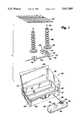
- FIG. 1is an exploded perspective view of a liquid fuel campstove
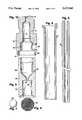
- FIG. 2is a fragmentary sectional view of the generator and fuel feed assembly of the campstove;
- FIG. 3is an enlarged fragmentary sectional view of the bottom portion of the fuel feed tube assembly within the circle 3--3 of FIG. 2;
- FIG. 4is a view similar to FIG. 3 showing the fuel-regulating valve in the restricting position
- FIG. 5is an enlarged sectional view of the fuel tip
- FIG. 6is a plan view of the screen for the fuel tip
- FIG. 7is a view of the fuel-regulating ball valve
- FIG. 8is a sectional view of the outer tube or air tube of the fuel feed tube assembly
- FIG. 9is a fragmentary sectional view of the inner tube or fuel tube of the fuel feed tube assembly.
- FIG. 10is a sectional view of the fuel feed tube connector
- FIG. 11is a view similar to FIG. 2 of an alternate embodiment
- FIG. 12is an enlarged fragmentary view of the portion of FIG. 11 within the circle 12--12;
- FIG. 13is a view similar to FIG. 12 showing the fuel-regulating valve in the restricting position.
- FIG. 14is an elevational view of the fuel regulating valve of FIGS. 11-13.
- the inventionwill be explained with reference to a campstove 20 illustrated in FIG. 1.
- the inventioncan also be used in lanterns and other liquid fuel appliances.
- the campstove 20includes a case 21, a liquid fuel tank 22, a burner assembly 23, and a grate 24.
- the case 21includes a bottom wall 25, front and back walls 26 and 27, a pair of side walls 28 and 29, and a lid 30 which is hingedly secured to the back wall 27.
- a pair of windscreens 31 and 32are hingedly secured to the bottom surface of the lid.
- the fuel tank 22is a conventional Coleman liquid fuel tank which includes a fill spout 34 and an air pump assembly 35.
- the fuel tankis removably mounted on the front wall of the case by a pair of mounting hooks 36 which can be inserted through slots in the front wall.
- a generator and fuel feed assembly 38is threadedly secured to the top of the fuel tank.
- the assembly 38includes a fuel control valve assembly 39, a generator assembly 40, and a fuel feed tube assembly 41.
- the control valve assembly and generator assemblycan be conventional.
- the control valve assemblyincludes a valve housing 42 and a valve stem 43 which is threadedly engaged in a central bore 44 of the housing.
- the inner end 45 of the valve stemis tapered and cooperates with a valve seat 46 in the valve housing to shut off fuel flow through the valve housing.
- the outer end of the valve stemextends through a nut 47 on the valve housing, and the valve stem can be rotated by a knob 48 (FIG. 1).
- a bushing 49extends downwardly from the valve housing and includes external threads 50 for engaging the fuel tank.
- the generator assemblyincludes a generator tube 51, an end cap 52 which is provided with a fuel orifice or jet nozzle 53, and a rod 54 which is threadedly secured to the valve stem 43.
- a needle 55is mounted on the end of the rod 54 and extends through the jet nozzle 53 when the valve is closed.
- a helical spring 56surrounds the rod for improving heat transfer to the fuel which flows through the generator tube.
- the burner assembly 23includes a main burner 60 and an auxiliary burner 61 which are connected by a crossover tube 62.
- Each of the burnersis a conventional Coleman burner and includes a burner box 63 having a top flange 64, a burner bowl 65 which is supported by the top flange, a plurality of burner rings 66, and a cap 67.
- a bolt 68is screwed into a bushing on the burner box and clamps the parts of the burner together.
- the particular burner rings illustratedhave been sold for many years under the trademark Band-A-Blu and are described, for example, in U.S. Pat. No. 3,933,146.
- the burner ringsinclude alternating flat and corrugated rings which provide a plurality of fuel outlet orifices.
- a generally U-shaped venturi or bunsen tube 69includes an open end 70 and a second or bottom end which extends into an inlet opening in the burner box 63 of the main burner 60.
- the generator tube 51extends through an opening in the front wall of the case, over the main burner 60, and into the open end 70 of the venturi tube 69.
- the fuel feed tube assembly 41includes a pair of inner and outer concentric tubes 74 and 75, the upper ends of which are secured to a connector 76.
- the connector 76is screwed into the bushing 49 of the valve assembly.
- the connectoris provided with a central bore 77 (FIG. 10).
- the boreincludes a plurality of stepped portions of increasing diameter--an upper outlet portion 78 having a small diameter, a second portion 79 of larger diameter, a larger third portion 80, and an end portion 81.
- the inner tube 74(see also FIG. 9) is secured within the portion 79 by an interference fit and may be further secured by brazing.
- the upper end of the outer tube 75includes a flared flange 82 (FIG. 8) which is sized to be inserted into the portion 81 of the bore, and the outer tube is secured by crimping the thin end wall 83 which forms the bore 81 against the flange 82.
- An annular air passage 85(FIGS. 2-4) is formed between the inner and outer tubes 74 and 75, and the air passage communicates with the upper portion of the fuel tank through an air inlet 86 (FIG. 10) in the connector 76.
- the air inlet 86is positioned above the fuel level in the fuel tank when the tank is full.
- a fuel tip 88is secured to the bottom of the outer tube 75.
- the fuel tipincludes a cylindrical side wall 89 and a transverse wall 90.
- a main fuel inlet opening 91is provided in the transverse wall 90, and a smaller side fuel inlet opening 92 is provided through the side wall 89.
- the fuel feed tube assembly 41is immersed in the liquid fuel contained by the fuel tank 22.
- the bottom end of the fuel tip 88is positioned adjacent the bottom of the fuel tank, and the air inlet opening 86 is positioned above the level of the liquid fuel when the fuel tank is full.
- the fuel tankis pressurized with air by operating the air pump 35.
- the continued low pressure area above the ballcauses air to be drawn through the air inlet opening 86 and the annular air passage 85.
- the airmixes with the fuel in a mixing chamber 96 below the bottom end of the inner fuel tube 74.
- the fuel/air mixtureflows upwardly through the inner fuel tube 74 and into the generator tube 51 and is discharged through the jet orifice 53 in the form of fuel-vapor-laden air and atomized droplets of fuel.
- the fuel/air mixtureflows into the main burner 60, it can be ignited by a lit match, sparking device, or the like.
- the flame of the burnerheats the generator assembly 40 and vaporizes the fuel in the generator.
- the fueltakes more volume in the generator, and flow through the inner fuel feed tube 74 is reduced.
- the fuel floweventually is reduced to a point where the pressure above and below the main fuel inlet opening approaches equilibrium and the ball 94 can no longer be held up by the fuel flow.
- the ballthen falls to the mesh or screen 96. Without the ball 94 blocking the main fuel inlet opening 91, fuel is free to flow through the main inlet opening 91.
- Fuel flow through the main inlet opening 91is sufficient to satisfy the flow through the generator tube, and there is insufficient suction to draw air downwardly through the annular air passage 85 so that only fuel without air flows upwardly through the inner fuel tube 74.
- the generator assembly 40does not always vaporize fuel smoothly, which may cause a pulsing action in the inner fuel tube 74.
- the pulsing actioncan cause the ball 94 to move up and down and partially block the main fuel inlet opening 91.
- the pulsing actionis dampened by the small outlet orifice 78 (FIG. 10) at the upper end of the connector 76.
- the ball 94regulates the flow of fuel and air through the inner fuel tube 74 by moving between a lower or running position in which the fuel inlet opening 91 is unobstructed and a start position in which the fuel inlet opening 91 is blocked by the ball. It is also possible to design the inlet opening 91 so that the inlet opening 91 is not completely obstructed by the ball in the start position and some fuel can flow through the inlet opening. The side inlet opening 92 can then be modified or omitted.
- the size and weight of the ball 94, the size of the fuel inlet opening 91 and the diameter of chamber 93are selected so that the ball will drop under its own weight when the generator is heated sufficiently to vaporize the fuel.
- the ballis advantageously made from plastic.
- FIGS. 11-14Another embodiment of a fuel regulating device is illustrated in FIGS. 11-14.
- the fuel feed tube assembly 100is identical to the fuel feed tube assembly 41 except for the lower end portion which is indicated by the circle 12--12.
- a fuel tip 101is connected to the lower end of the outer air tube 75 and includes a fuel inlet opening 102.
- a metal restricting rod 103acts as a fuel regulating valve and includes a shank 104 and a cylindrical piston or flange 105.
- the shankincludes an upper portion 106 which extends into the inner fuel tube 74 and a lower portion 107 which extends through the fuel inlet opening 102.
- the piston 105is sized to engage the bottom end of the outer air tube 75 but not obstruct flow of fuel past the piston and into the fuel tube 74.
- the lower portion 107 of the restricting rodincludes a restricting portion 107a which has a diameter slightly less than the diameter of the inlet opening 102 and a necked-down or small diameter portion 107b
- the diameter of orifice 102 and the size of rod 107are selected so that a reduced amount of fuel for lighting is allowed to flow to the burner.
Landscapes
- Engineering & Computer Science (AREA)
- Chemical & Material Sciences (AREA)
- Combustion & Propulsion (AREA)
- Mechanical Engineering (AREA)
- General Engineering & Computer Science (AREA)
- Spray-Type Burners (AREA)
- Combustion Of Fluid Fuel (AREA)
- Regulation And Control Of Combustion (AREA)
Abstract
Description
Claims (12)
Priority Applications (4)
| Application Number | Priority Date | Filing Date | Title |
|---|---|---|---|
| US08/324,258US5417565A (en) | 1994-10-17 | 1994-10-17 | Automatic instant lighting system for liquid fuel burner |
| CA 2142215CA2142215C (en) | 1994-10-17 | 1995-02-10 | Automatic instant lighting system for liquid fuel burner |
| JP11198695AJP2648131B2 (en) | 1994-10-17 | 1995-05-10 | Liquid fuel combustion device |
| KR1019950011529AKR960014765A (en) | 1994-10-17 | 1995-05-11 | Automatic Fuel Control Mechanism for Liquid Fuel Burner |
Applications Claiming Priority (1)
| Application Number | Priority Date | Filing Date | Title |
|---|---|---|---|
| US08/324,258US5417565A (en) | 1994-10-17 | 1994-10-17 | Automatic instant lighting system for liquid fuel burner |
Publications (1)
| Publication Number | Publication Date |
|---|---|
| US5417565Atrue US5417565A (en) | 1995-05-23 |
Family
ID=23262801
Family Applications (1)
| Application Number | Title | Priority Date | Filing Date |
|---|---|---|---|
| US08/324,258Expired - Fee RelatedUS5417565A (en) | 1994-10-17 | 1994-10-17 | Automatic instant lighting system for liquid fuel burner |
Country Status (4)
| Country | Link |
|---|---|
| US (1) | US5417565A (en) |
| JP (1) | JP2648131B2 (en) |
| KR (1) | KR960014765A (en) |
| CA (1) | CA2142215C (en) |
Cited By (34)
| Publication number | Priority date | Publication date | Assignee | Title |
|---|---|---|---|---|
| US5878730A (en)* | 1996-06-14 | 1999-03-09 | Williams; Parke Donald | Lawn mower powered by alternative fuels using a fuel injector adapted for gaseous fuels |
| US6142141A (en)* | 1997-05-05 | 2000-11-07 | The Coleman Company, Inc. | Airflow diffuser for use with a forced-air space heater and a forced-air space heater using the same |
| EP1346737A1 (en)* | 2002-03-22 | 2003-09-24 | CODMAN & SHURTLEFF, INC. | Infusion pump with access regulator |
| US6699036B2 (en) | 2002-05-06 | 2004-03-02 | Weber-Stephen Products Company | Curvilinear burner tube |
| US6746233B2 (en) | 2001-09-25 | 2004-06-08 | L. B. White Co., Inc. | Semi-automatic gas pilot orifice clean-out device |
| US20040173200A1 (en)* | 2003-03-07 | 2004-09-09 | Mohammed Shoeb | Gas burner with flame stabilization structure |
| USD498976S1 (en) | 2003-10-17 | 2004-11-30 | The Coleman Company, Inc. | Camping stove baffle |
| US20060021997A1 (en)* | 2004-08-02 | 2006-02-02 | Ario Lin | Heat sink for gas-fueled appliance |
| US20060247584A1 (en)* | 2005-03-04 | 2006-11-02 | C.R. Bard, Inc. | Access port identification systems and methods |
| US20070087297A1 (en)* | 2005-10-17 | 2007-04-19 | The Coleman Company, Inc. | Liquid fuel backpacking stove |
| US7568911B1 (en)* | 2003-03-17 | 2009-08-04 | Diana Clifton Draper | Camping stove with preheat system |
| US20090204074A1 (en)* | 2005-04-27 | 2009-08-13 | C. R. Bard, Inc. | Methods of power injecting a fluid through an access port |
| US7947022B2 (en) | 2005-03-04 | 2011-05-24 | C. R. Bard, Inc. | Access port identification systems and methods |
| US8021324B2 (en) | 2007-07-19 | 2011-09-20 | Medical Components, Inc. | Venous access port assembly with X-ray discernable indicia |
| US8029482B2 (en) | 2005-03-04 | 2011-10-04 | C. R. Bard, Inc. | Systems and methods for radiographically identifying an access port |
| US8177762B2 (en) | 1998-12-07 | 2012-05-15 | C. R. Bard, Inc. | Septum including at least one identifiable feature, access ports including same, and related methods |
| US8202259B2 (en) | 2005-03-04 | 2012-06-19 | C. R. Bard, Inc. | Systems and methods for identifying an access port |
| US8257325B2 (en) | 2007-06-20 | 2012-09-04 | Medical Components, Inc. | Venous access port with molded and/or radiopaque indicia |
| USD676955S1 (en) | 2010-12-30 | 2013-02-26 | C. R. Bard, Inc. | Implantable access port |
| USD682416S1 (en) | 2010-12-30 | 2013-05-14 | C. R. Bard, Inc. | Implantable access port |
| US8641676B2 (en) | 2005-04-27 | 2014-02-04 | C. R. Bard, Inc. | Infusion apparatuses and methods of use |
| US8715244B2 (en) | 2009-07-07 | 2014-05-06 | C. R. Bard, Inc. | Extensible internal bolster for a medical device |
| US8932271B2 (en) | 2008-11-13 | 2015-01-13 | C. R. Bard, Inc. | Implantable medical devices including septum-based indicators |
| US9079004B2 (en) | 2009-11-17 | 2015-07-14 | C. R. Bard, Inc. | Overmolded access port including anchoring and identification features |
| US9265912B2 (en) | 2006-11-08 | 2016-02-23 | C. R. Bard, Inc. | Indicia informative of characteristics of insertable medical devices |
| US20160153654A1 (en)* | 2013-07-18 | 2016-06-02 | Johns Manville | Combustion burner |
| US9474888B2 (en) | 2005-03-04 | 2016-10-25 | C. R. Bard, Inc. | Implantable access port including a sandwiched radiopaque insert |
| US9579496B2 (en) | 2007-11-07 | 2017-02-28 | C. R. Bard, Inc. | Radiopaque and septum-based indicators for a multi-lumen implantable port |
| US9610432B2 (en) | 2007-07-19 | 2017-04-04 | Innovative Medical Devices, Llc | Venous access port assembly with X-ray discernable indicia |
| US9642986B2 (en) | 2006-11-08 | 2017-05-09 | C. R. Bard, Inc. | Resource information key for an insertable medical device |
| US10307581B2 (en) | 2005-04-27 | 2019-06-04 | C. R. Bard, Inc. | Reinforced septum for an implantable medical device |
| US10378759B1 (en) | 2017-06-30 | 2019-08-13 | Agricultural Flaming Innovations, Llc | Torch, and hood assembly, with provision for atomizing fuel for easy combustion, and provision for auto-ignition of fuel |
| US11890443B2 (en) | 2008-11-13 | 2024-02-06 | C. R. Bard, Inc. | Implantable medical devices including septum-based indicators |
| US11982443B1 (en) | 2018-07-02 | 2024-05-14 | Agricultural Flamming Innovations, Llc | Torch and hood assembly comprising a chimney and double plated enclosure, provision for atomizing fuel for easy combustion, and provision for auto-ignition of fuel |
Families Citing this family (2)
| Publication number | Priority date | Publication date | Assignee | Title |
|---|---|---|---|---|
| KR100675428B1 (en)* | 2005-09-30 | 2007-01-30 | 김연수 | Processing method of green corn eggs |
| EP2049837A2 (en)* | 2006-08-04 | 2009-04-22 | The Coleman Company, Inc. | Backpacking stove |
Citations (14)
| Publication number | Priority date | Publication date | Assignee | Title |
|---|---|---|---|---|
| US1013822A (en)* | 1911-02-18 | 1912-01-02 | George B Robbins | Heater. |
| US1127455A (en)* | 1914-11-03 | 1915-02-09 | Friedrich Krauss | Gas-burner. |
| US1749629A (en)* | 1927-12-30 | 1930-03-04 | Coleman Lamp And Stove Co | Apparatus for burning fuel |
| US1852845A (en)* | 1928-05-23 | 1932-04-05 | American Gas Machine Company | Lighter of instantaneous type |
| US1887140A (en)* | 1929-10-28 | 1932-11-08 | Frank V Risinger | Hydrocarbon burner |
| US2025837A (en)* | 1934-05-18 | 1935-12-31 | Boyd W Tullis | Liquid hydrocarbon fuel burning device |
| US2139819A (en)* | 1935-08-02 | 1938-12-13 | Graetz Fritz | Preheater |
| US2321034A (en)* | 1938-06-03 | 1943-06-08 | Newark Stove Company | Liquid fuel stove |
| US2553817A (en)* | 1948-09-01 | 1951-05-22 | Jet Heet Inc | Thermally actuated pump |
| USRE24457E (en)* | 1958-04-15 | Folding berth | ||
| US3876364A (en)* | 1973-07-12 | 1975-04-08 | Dennis V Hefling | Fuel control means for camp stoves |
| US3933146A (en)* | 1975-03-12 | 1976-01-20 | The Coleman Company, Inc. | Portable single burner campstove |
| US4825897A (en)* | 1988-05-19 | 1989-05-02 | Shade Stephen A | Flow control valve |
| US5336084A (en)* | 1993-06-09 | 1994-08-09 | The Coleman Company, Inc. | Liquid fuel campstove with electronic ignition |
- 1994
- 1994-10-17USUS08/324,258patent/US5417565A/ennot_activeExpired - Fee Related
- 1995
- 1995-02-10CACA 2142215patent/CA2142215C/ennot_activeExpired - Fee Related
- 1995-05-10JPJP11198695Apatent/JP2648131B2/ennot_activeExpired - Lifetime
- 1995-05-11KRKR1019950011529Apatent/KR960014765A/ennot_activeWithdrawn
Patent Citations (14)
| Publication number | Priority date | Publication date | Assignee | Title |
|---|---|---|---|---|
| USRE24457E (en)* | 1958-04-15 | Folding berth | ||
| US1013822A (en)* | 1911-02-18 | 1912-01-02 | George B Robbins | Heater. |
| US1127455A (en)* | 1914-11-03 | 1915-02-09 | Friedrich Krauss | Gas-burner. |
| US1749629A (en)* | 1927-12-30 | 1930-03-04 | Coleman Lamp And Stove Co | Apparatus for burning fuel |
| US1852845A (en)* | 1928-05-23 | 1932-04-05 | American Gas Machine Company | Lighter of instantaneous type |
| US1887140A (en)* | 1929-10-28 | 1932-11-08 | Frank V Risinger | Hydrocarbon burner |
| US2025837A (en)* | 1934-05-18 | 1935-12-31 | Boyd W Tullis | Liquid hydrocarbon fuel burning device |
| US2139819A (en)* | 1935-08-02 | 1938-12-13 | Graetz Fritz | Preheater |
| US2321034A (en)* | 1938-06-03 | 1943-06-08 | Newark Stove Company | Liquid fuel stove |
| US2553817A (en)* | 1948-09-01 | 1951-05-22 | Jet Heet Inc | Thermally actuated pump |
| US3876364A (en)* | 1973-07-12 | 1975-04-08 | Dennis V Hefling | Fuel control means for camp stoves |
| US3933146A (en)* | 1975-03-12 | 1976-01-20 | The Coleman Company, Inc. | Portable single burner campstove |
| US4825897A (en)* | 1988-05-19 | 1989-05-02 | Shade Stephen A | Flow control valve |
| US5336084A (en)* | 1993-06-09 | 1994-08-09 | The Coleman Company, Inc. | Liquid fuel campstove with electronic ignition |
Cited By (95)
| Publication number | Priority date | Publication date | Assignee | Title |
|---|---|---|---|---|
| US5878730A (en)* | 1996-06-14 | 1999-03-09 | Williams; Parke Donald | Lawn mower powered by alternative fuels using a fuel injector adapted for gaseous fuels |
| US6142141A (en)* | 1997-05-05 | 2000-11-07 | The Coleman Company, Inc. | Airflow diffuser for use with a forced-air space heater and a forced-air space heater using the same |
| US8608713B2 (en) | 1998-12-07 | 2013-12-17 | C. R. Bard, Inc. | Septum feature for identification of an access port |
| US8177762B2 (en) | 1998-12-07 | 2012-05-15 | C. R. Bard, Inc. | Septum including at least one identifiable feature, access ports including same, and related methods |
| US6746233B2 (en) | 2001-09-25 | 2004-06-08 | L. B. White Co., Inc. | Semi-automatic gas pilot orifice clean-out device |
| EP1346737A1 (en)* | 2002-03-22 | 2003-09-24 | CODMAN & SHURTLEFF, INC. | Infusion pump with access regulator |
| US6805687B2 (en) | 2002-03-22 | 2004-10-19 | Codman & Shurtleff, Inc. | Infusion pump with access regulator |
| US6699036B2 (en) | 2002-05-06 | 2004-03-02 | Weber-Stephen Products Company | Curvilinear burner tube |
| US6945774B2 (en) | 2003-03-07 | 2005-09-20 | Weber-Stephen Products Co. | Gas burner with flame stabilization structure |
| US20040173200A1 (en)* | 2003-03-07 | 2004-09-09 | Mohammed Shoeb | Gas burner with flame stabilization structure |
| US7568911B1 (en)* | 2003-03-17 | 2009-08-04 | Diana Clifton Draper | Camping stove with preheat system |
| USD498976S1 (en) | 2003-10-17 | 2004-11-30 | The Coleman Company, Inc. | Camping stove baffle |
| US20060021997A1 (en)* | 2004-08-02 | 2006-02-02 | Ario Lin | Heat sink for gas-fueled appliance |
| US7785302B2 (en) | 2005-03-04 | 2010-08-31 | C. R. Bard, Inc. | Access port identification systems and methods |
| US11077291B2 (en) | 2005-03-04 | 2021-08-03 | Bard Peripheral Vascular, Inc. | Implantable access port including a sandwiched radiopaque insert |
| US10675401B2 (en) | 2005-03-04 | 2020-06-09 | Bard Peripheral Vascular, Inc. | Access port identification systems and methods |
| US10905868B2 (en) | 2005-03-04 | 2021-02-02 | Bard Peripheral Vascular, Inc. | Systems and methods for radiographically identifying an access port |
| US20100211026A2 (en)* | 2005-03-04 | 2010-08-19 | C. R. Bard, Inc. | Access port identification systems and methods |
| US8939947B2 (en) | 2005-03-04 | 2015-01-27 | C. R. Bard, Inc. | Systems and methods for radiographically identifying an access port |
| US7947022B2 (en) | 2005-03-04 | 2011-05-24 | C. R. Bard, Inc. | Access port identification systems and methods |
| US7959615B2 (en) | 2005-03-04 | 2011-06-14 | C. R. Bard, Inc. | Access port identification systems and methods |
| US10265512B2 (en) | 2005-03-04 | 2019-04-23 | Bard Peripheral Vascular, Inc. | Implantable access port including a sandwiched radiopaque insert |
| US10238850B2 (en) | 2005-03-04 | 2019-03-26 | Bard Peripheral Vascular, Inc. | Systems and methods for radiographically identifying an access port |
| US8029482B2 (en) | 2005-03-04 | 2011-10-04 | C. R. Bard, Inc. | Systems and methods for radiographically identifying an access port |
| US10857340B2 (en) | 2005-03-04 | 2020-12-08 | Bard Peripheral Vascular, Inc. | Systems and methods for radiographically identifying an access port |
| US8202259B2 (en) | 2005-03-04 | 2012-06-19 | C. R. Bard, Inc. | Systems and methods for identifying an access port |
| US10179230B2 (en) | 2005-03-04 | 2019-01-15 | Bard Peripheral Vascular, Inc. | Systems and methods for radiographically identifying an access port |
| US9682186B2 (en) | 2005-03-04 | 2017-06-20 | C. R. Bard, Inc. | Access port identification systems and methods |
| US8382724B2 (en) | 2005-03-04 | 2013-02-26 | C. R. Bard, Inc. | Systems and methods for radiographically identifying an access port |
| US8382723B2 (en) | 2005-03-04 | 2013-02-26 | C. R. Bard, Inc. | Access port identification systems and methods |
| US9603992B2 (en) | 2005-03-04 | 2017-03-28 | C. R. Bard, Inc. | Access port identification systems and methods |
| US9603993B2 (en) | 2005-03-04 | 2017-03-28 | C. R. Bard, Inc. | Access port identification systems and methods |
| US9474888B2 (en) | 2005-03-04 | 2016-10-25 | C. R. Bard, Inc. | Implantable access port including a sandwiched radiopaque insert |
| US8585663B2 (en) | 2005-03-04 | 2013-11-19 | C. R. Bard, Inc. | Access port identification systems and methods |
| US8603052B2 (en) | 2005-03-04 | 2013-12-10 | C. R. Bard, Inc. | Access port identification systems and methods |
| US20060247584A1 (en)* | 2005-03-04 | 2006-11-02 | C.R. Bard, Inc. | Access port identification systems and methods |
| US10307581B2 (en) | 2005-04-27 | 2019-06-04 | C. R. Bard, Inc. | Reinforced septum for an implantable medical device |
| US10661068B2 (en) | 2005-04-27 | 2020-05-26 | Bard Peripheral Vascular, Inc. | Assemblies for identifying a power injectable access port |
| US10052470B2 (en) | 2005-04-27 | 2018-08-21 | Bard Peripheral Vascular, Inc. | Assemblies for identifying a power injectable access port |
| US8805478B2 (en) | 2005-04-27 | 2014-08-12 | C. R. Bard, Inc. | Methods of performing a power injection procedure including identifying features of a subcutaneously implanted access port for delivery of contrast media |
| US10016585B2 (en) | 2005-04-27 | 2018-07-10 | Bard Peripheral Vascular, Inc. | Assemblies for identifying a power injectable access port |
| US9937337B2 (en) | 2005-04-27 | 2018-04-10 | C. R. Bard, Inc. | Assemblies for identifying a power injectable access port |
| US8641688B2 (en) | 2005-04-27 | 2014-02-04 | C. R. Bard, Inc. | Assemblies for identifying a power injectable access port |
| US20090204074A1 (en)* | 2005-04-27 | 2009-08-13 | C. R. Bard, Inc. | Methods of power injecting a fluid through an access port |
| US10780257B2 (en) | 2005-04-27 | 2020-09-22 | Bard Peripheral Vascular, Inc. | Assemblies for identifying a power injectable access port |
| US8641676B2 (en) | 2005-04-27 | 2014-02-04 | C. R. Bard, Inc. | Infusion apparatuses and methods of use |
| US20090216216A1 (en)* | 2005-04-27 | 2009-08-27 | C. R. Bard, Inc. | Methods of performing a power injection procedure |
| US9421352B2 (en) | 2005-04-27 | 2016-08-23 | C. R. Bard, Inc. | Infusion apparatuses and methods of use |
| US8545460B2 (en) | 2005-04-27 | 2013-10-01 | C. R. Bard, Inc. | Infusion apparatuses and related methods |
| US10183157B2 (en) | 2005-04-27 | 2019-01-22 | Bard Peripheral Vascular, Inc. | Assemblies for identifying a power injectable access port |
| US10625065B2 (en) | 2005-04-27 | 2020-04-21 | Bard Peripheral Vascular, Inc. | Assemblies for identifying a power injectable access port |
| US8025639B2 (en) | 2005-04-27 | 2011-09-27 | C. R. Bard, Inc. | Methods of power injecting a fluid through an access port |
| US8475417B2 (en) | 2005-04-27 | 2013-07-02 | C. R. Bard, Inc. | Assemblies for identifying a power injectable access port |
| US20090227951A1 (en)* | 2005-04-27 | 2009-09-10 | C. R. Bard, Inc | Assemblies for identifying a power injectable access port |
| WO2007047132A3 (en)* | 2005-10-17 | 2007-08-16 | Coleman Co | Liquid fuel backpacking stove |
| US20070087297A1 (en)* | 2005-10-17 | 2007-04-19 | The Coleman Company, Inc. | Liquid fuel backpacking stove |
| US11878137B2 (en) | 2006-10-18 | 2024-01-23 | Medical Components, Inc. | Venous access port assembly with X-ray discernable indicia |
| US10556090B2 (en) | 2006-11-08 | 2020-02-11 | C. R. Bard, Inc. | Resource information key for an insertable medical device |
| US9642986B2 (en) | 2006-11-08 | 2017-05-09 | C. R. Bard, Inc. | Resource information key for an insertable medical device |
| US10092725B2 (en) | 2006-11-08 | 2018-10-09 | C. R. Bard, Inc. | Resource information key for an insertable medical device |
| US9265912B2 (en) | 2006-11-08 | 2016-02-23 | C. R. Bard, Inc. | Indicia informative of characteristics of insertable medical devices |
| US8257325B2 (en) | 2007-06-20 | 2012-09-04 | Medical Components, Inc. | Venous access port with molded and/or radiopaque indicia |
| US11938296B2 (en) | 2007-06-20 | 2024-03-26 | Medical Components, Inc. | Venous access port with molded and/or radiopaque indicia |
| US11478622B2 (en) | 2007-06-20 | 2022-10-25 | Medical Components, Inc. | Venous access port with molded and/or radiopaque indicia |
| US11406808B2 (en) | 2007-06-20 | 2022-08-09 | Medical Components, Inc. | Venous access port with molded and/or radiopaque indicia |
| US8852160B2 (en) | 2007-06-20 | 2014-10-07 | Medical Components, Inc. | Venous access port with molded and/or radiopaque indicia |
| US9533133B2 (en) | 2007-06-20 | 2017-01-03 | Medical Components, Inc. | Venous access port with molded and/or radiopaque indicia |
| US9517329B2 (en) | 2007-07-19 | 2016-12-13 | Medical Components, Inc. | Venous access port assembly with X-ray discernable indicia |
| US12274850B2 (en) | 2007-07-19 | 2025-04-15 | Medical Components, Inc. | Venous access port assembly with X-ray discernable indicia |
| US11547843B2 (en) | 2007-07-19 | 2023-01-10 | Innovative Medical Devices, Llc | Venous access port assembly with x-ray discernable indicia |
| US9610432B2 (en) | 2007-07-19 | 2017-04-04 | Innovative Medical Devices, Llc | Venous access port assembly with X-ray discernable indicia |
| US8021324B2 (en) | 2007-07-19 | 2011-09-20 | Medical Components, Inc. | Venous access port assembly with X-ray discernable indicia |
| US10874842B2 (en) | 2007-07-19 | 2020-12-29 | Medical Components, Inc. | Venous access port assembly with X-ray discernable indicia |
| US10639465B2 (en) | 2007-07-19 | 2020-05-05 | Innovative Medical Devices, Llc | Venous access port assembly with X-ray discernable indicia |
| US10792485B2 (en) | 2007-11-07 | 2020-10-06 | C. R. Bard, Inc. | Radiopaque and septum-based indicators for a multi-lumen implantable port |
| US9579496B2 (en) | 2007-11-07 | 2017-02-28 | C. R. Bard, Inc. | Radiopaque and septum-based indicators for a multi-lumen implantable port |
| US11638810B2 (en) | 2007-11-07 | 2023-05-02 | C. R. Bard, Inc. | Radiopaque and septum-based indicators for a multi-lumen implantable port |
| US10086186B2 (en) | 2007-11-07 | 2018-10-02 | C. R. Bard, Inc. | Radiopaque and septum-based indicators for a multi-lumen implantable port |
| US10052471B2 (en) | 2008-11-13 | 2018-08-21 | C. R. Bard, Inc. | Implantable medical devices including septum-based indicators |
| US8932271B2 (en) | 2008-11-13 | 2015-01-13 | C. R. Bard, Inc. | Implantable medical devices including septum-based indicators |
| US11890443B2 (en) | 2008-11-13 | 2024-02-06 | C. R. Bard, Inc. | Implantable medical devices including septum-based indicators |
| US10773066B2 (en) | 2008-11-13 | 2020-09-15 | C. R. Bard, Inc. | Implantable medical devices including septum-based indicators |
| US8715244B2 (en) | 2009-07-07 | 2014-05-06 | C. R. Bard, Inc. | Extensible internal bolster for a medical device |
| US9248268B2 (en) | 2009-11-17 | 2016-02-02 | C. R. Bard, Inc. | Overmolded access port including anchoring and identification features |
| US9079004B2 (en) | 2009-11-17 | 2015-07-14 | C. R. Bard, Inc. | Overmolded access port including anchoring and identification features |
| US11759615B2 (en) | 2009-11-17 | 2023-09-19 | Bard Peripheral Vascular, Inc. | Overmolded access port including anchoring and identification features |
| US10912935B2 (en) | 2009-11-17 | 2021-02-09 | Bard Peripheral Vascular, Inc. | Method for manufacturing a power-injectable access port |
| US10155101B2 (en) | 2009-11-17 | 2018-12-18 | Bard Peripheral Vascular, Inc. | Overmolded access port including anchoring and identification features |
| US9717895B2 (en) | 2009-11-17 | 2017-08-01 | C. R. Bard, Inc. | Overmolded access port including anchoring and identification features |
| USD682416S1 (en) | 2010-12-30 | 2013-05-14 | C. R. Bard, Inc. | Implantable access port |
| USD676955S1 (en) | 2010-12-30 | 2013-02-26 | C. R. Bard, Inc. | Implantable access port |
| US20160153654A1 (en)* | 2013-07-18 | 2016-06-02 | Johns Manville | Combustion burner |
| US10858278B2 (en)* | 2013-07-18 | 2020-12-08 | Johns Manville | Combustion burner |
| US10378759B1 (en) | 2017-06-30 | 2019-08-13 | Agricultural Flaming Innovations, Llc | Torch, and hood assembly, with provision for atomizing fuel for easy combustion, and provision for auto-ignition of fuel |
| US11982443B1 (en) | 2018-07-02 | 2024-05-14 | Agricultural Flamming Innovations, Llc | Torch and hood assembly comprising a chimney and double plated enclosure, provision for atomizing fuel for easy combustion, and provision for auto-ignition of fuel |
Also Published As
| Publication number | Publication date |
|---|---|
| JP2648131B2 (en) | 1997-08-27 |
| CA2142215A1 (en) | 1996-04-18 |
| KR960014765A (en) | 1996-05-22 |
| JPH08121709A (en) | 1996-05-17 |
| CA2142215C (en) | 1998-10-20 |
Similar Documents
| Publication | Publication Date | Title |
|---|---|---|
| US5417565A (en) | Automatic instant lighting system for liquid fuel burner | |
| US20070087297A1 (en) | Liquid fuel backpacking stove | |
| CA2124362C (en) | Liquid fuel campstove with electronic ignition | |
| US3844270A (en) | Energy conversion system | |
| EP0694728B1 (en) | Liquid fuel lantern with electronic ignition | |
| CA1082938A (en) | Lantern with kerosene preheater | |
| US3485567A (en) | Liquid fuel burning appliance and components therefor | |
| US4353348A (en) | Energy conversion system | |
| US4025291A (en) | Energy conversion system | |
| US2363099A (en) | Burner for fuels containing tetraethyl lead and other objectionable foreign matter | |
| US3376100A (en) | Combustion apparatus | |
| GB1580383A (en) | Burner for liquid fuel | |
| US2193085A (en) | Liquid fuel burner | |
| US3351042A (en) | Heater | |
| US2135689A (en) | Lamp | |
| US2008882A (en) | Lamp | |
| US974795A (en) | Crude-oil burner. | |
| CN215723387U (en) | Alcohol vaporization stove structure | |
| RU2033573C1 (en) | Burner | |
| US2256305A (en) | Burner construction | |
| US2023072A (en) | Oil burner | |
| CN2163949Y (en) | Bucket type reinforced oil-gas two-purpose burner | |
| US2494394A (en) | Heating apparatus and fuel flow controlling means therefor | |
| US1874346A (en) | Fuel burner | |
| CN2196262Y (en) | Liquid synthetic fuel range |
Legal Events
| Date | Code | Title | Description |
|---|---|---|---|
| AS | Assignment | Owner name:COLEMAN COMPANY, INC., THE, KANSAS Free format text:ASSIGNMENT OF ASSIGNORS INTEREST;ASSIGNOR:LONG, NORRIS R.;REEL/FRAME:007261/0889 Effective date:19941010 | |
| FPAY | Fee payment | Year of fee payment:4 | |
| AS | Assignment | Owner name:FIRST UNION NATIONAL BANK, AS ADMINISTRATIVE AGENT Free format text:SECURITY INTEREST;ASSIGNOR:COLEMAN COMPANY, INC., THE (DELAWARE CORPORATION);REEL/FRAME:010238/0384 Effective date:19990514 | |
| AS | Assignment | Owner name:FIRST UNION NATIONAL BANK, AS ADMINISTRATIVE AGEN, Free format text:SECURITY AGREEMENT;ASSIGNOR:SUNBEAM CORPORATION (DE CORPORATION);REEL/FRAME:010685/0133 Effective date:20000106 | |
| AS | Assignment | Owner name:FIRST UNION NATIONAL BANK, AS ADMINISTRATIVE AGENT Free format text:DOCUMENT RECORDED AT REEL/FRAME 10685/133 CONTAINED ERROR IN THE NAME OF THE ASSIGNOR;ASSIGNOR:THE COLEMAN COMPANY, INC. (DE CORPORATION);REEL/FRAME:010892/0824 Effective date:20000106 Owner name:FIRST UNION NATIONAL BANK, AS ADMINISTRATIVE AGENT Free format text:DOCUMENT RECORDED AT REEL 10685 FRAME 0133 CONTAINED AN ERROR IN THE NAME OF THE ASSIGNOR. SECURITY AGREEMENT RE-RECORDED TO CORRECT ERROR ON STATED REEL.;ASSIGNOR:COLEMAN COMPANY, INC., THE (DE CORPORATION);REEL/FRAME:010942/0680 Effective date:20000106 | |
| AS | Assignment | Owner name:FIRST UNION NATIONAL BANK, AS ADMINISTRATIVE AGENT Free format text:SECURITY INTEREST;ASSIGNOR:COLEMAN COMPANY, INC., THE;REEL/FRAME:011111/0340 Effective date:20000929 | |
| REMI | Maintenance fee reminder mailed | ||
| AS | Assignment | Owner name:COLEMAN COMPANY, THE, KANSAS Free format text:TERMINATION AND RELEASE OF SECURITY INTEREST;ASSIGNOR:WACHOVIA BANK, NATIONAL ASSOCIATION (FORMERLY FIRST UNION NATIONAL BANK);REEL/FRAME:013986/0833 Effective date:20021213 Owner name:COLEMAN COMPANY, THE, KANSAS Free format text:TERMINATION AND RELEASE OF SECURITY;ASSIGNOR:WACHOVIA BANK, NATIONAL ASSOCIATION;REEL/FRAME:013998/0465 Effective date:20021213 | |
| LAPS | Lapse for failure to pay maintenance fees | ||
| STCH | Information on status: patent discontinuation | Free format text:PATENT EXPIRED DUE TO NONPAYMENT OF MAINTENANCE FEES UNDER 37 CFR 1.362 | |
| FP | Lapsed due to failure to pay maintenance fee | Effective date:20030523 |