US5417337A - Reusable and re-collapsible container and associated cap - Google Patents
Reusable and re-collapsible container and associated capDownload PDFInfo
- Publication number
- US5417337A US5417337AUS08/047,185US4718593AUS5417337AUS 5417337 AUS5417337 AUS 5417337AUS 4718593 AUS4718593 AUS 4718593AUS 5417337 AUS5417337 AUS 5417337A
- Authority
- US
- United States
- Prior art keywords
- side wall
- wall portion
- container
- cap
- upper side
- Prior art date
- Legal status (The legal status is an assumption and is not a legal conclusion. Google has not performed a legal analysis and makes no representation as to the accuracy of the status listed.)
- Expired - Lifetime
Links
- 230000002093peripheral effectEffects0.000claimsabstractdescription52
- 229920001684low density polyethylenePolymers0.000claimsdescription4
- 239000004702low-density polyethyleneSubstances0.000claimsdescription4
- 239000004743PolypropyleneSubstances0.000claimsdescription3
- -1polypropylenePolymers0.000claimsdescription3
- 229920001155polypropylenePolymers0.000claimsdescription3
- VGGSQFUCUMXWEO-UHFFFAOYSA-NEtheneChemical compoundC=CVGGSQFUCUMXWEO-UHFFFAOYSA-N0.000claims2
- 239000004033plasticSubstances0.000description5
- 229920003023plasticPolymers0.000description5
- 230000009471actionEffects0.000description4
- 239000000463materialSubstances0.000description4
- 230000004323axial lengthEffects0.000description3
- 230000014759maintenance of locationEffects0.000description3
- 230000006835compressionEffects0.000description2
- 238000007906compressionMethods0.000description2
- 238000010276constructionMethods0.000description2
- 230000007423decreaseEffects0.000description2
- 230000035622drinkingEffects0.000description2
- 230000009467reductionEffects0.000description2
- 230000002159abnormal effectEffects0.000description1
- 230000008859changeEffects0.000description1
- 230000003247decreasing effectEffects0.000description1
- 230000000694effectsEffects0.000description1
- 230000005489elastic deformationEffects0.000description1
- 238000001125extrusionMethods0.000description1
- 238000010348incorporationMethods0.000description1
- 238000007373indentationMethods0.000description1
- 238000004519manufacturing processMethods0.000description1
- 230000013011matingEffects0.000description1
- 238000012986modificationMethods0.000description1
- 230000004048modificationEffects0.000description1
- 230000003014reinforcing effectEffects0.000description1
- 239000010409thin filmSubstances0.000description1
- 230000007704transitionEffects0.000description1
Images


Classifications
- A—HUMAN NECESSITIES
- A47—FURNITURE; DOMESTIC ARTICLES OR APPLIANCES; COFFEE MILLS; SPICE MILLS; SUCTION CLEANERS IN GENERAL
- A47G—HOUSEHOLD OR TABLE EQUIPMENT
- A47G23/00—Other table equipment
- A47G23/02—Glass or bottle holders
- A47G23/0241—Glass or bottle holders for bottles; Decanters
- A—HUMAN NECESSITIES
- A61—MEDICAL OR VETERINARY SCIENCE; HYGIENE
- A61G—TRANSPORT, PERSONAL CONVEYANCES, OR ACCOMMODATION SPECIALLY ADAPTED FOR PATIENTS OR DISABLED PERSONS; OPERATING TABLES OR CHAIRS; CHAIRS FOR DENTISTRY; FUNERAL DEVICES
- A61G9/00—Bed-pans, urinals or other sanitary devices for bed-ridden persons; Cleaning devices therefor, e.g. combined with toilet-urinals
- A61G9/006—Urinals
- B—PERFORMING OPERATIONS; TRANSPORTING
- B65—CONVEYING; PACKING; STORING; HANDLING THIN OR FILAMENTARY MATERIAL
- B65D—CONTAINERS FOR STORAGE OR TRANSPORT OF ARTICLES OR MATERIALS, e.g. BAGS, BARRELS, BOTTLES, BOXES, CANS, CARTONS, CRATES, DRUMS, JARS, TANKS, HOPPERS, FORWARDING CONTAINERS; ACCESSORIES, CLOSURES, OR FITTINGS THEREFOR; PACKAGING ELEMENTS; PACKAGES
- B65D1/00—Rigid or semi-rigid containers having bodies formed in one piece, e.g. by casting metallic material, by moulding plastics, by blowing vitreous material, by throwing ceramic material, by moulding pulped fibrous material or by deep-drawing operations performed on sheet material
- B65D1/40—Details of walls
- B—PERFORMING OPERATIONS; TRANSPORTING
- B65—CONVEYING; PACKING; STORING; HANDLING THIN OR FILAMENTARY MATERIAL
- B65D—CONTAINERS FOR STORAGE OR TRANSPORT OF ARTICLES OR MATERIALS, e.g. BAGS, BARRELS, BOTTLES, BOXES, CANS, CARTONS, CRATES, DRUMS, JARS, TANKS, HOPPERS, FORWARDING CONTAINERS; ACCESSORIES, CLOSURES, OR FITTINGS THEREFOR; PACKAGING ELEMENTS; PACKAGES
- B65D21/00—Nestable, stackable or joinable containers; Containers of variable capacity
- B65D21/08—Containers of variable capacity
- B65D21/086—Collapsible or telescopic containers
- B—PERFORMING OPERATIONS; TRANSPORTING
- B65—CONVEYING; PACKING; STORING; HANDLING THIN OR FILAMENTARY MATERIAL
- B65D—CONTAINERS FOR STORAGE OR TRANSPORT OF ARTICLES OR MATERIALS, e.g. BAGS, BARRELS, BOTTLES, BOXES, CANS, CARTONS, CRATES, DRUMS, JARS, TANKS, HOPPERS, FORWARDING CONTAINERS; ACCESSORIES, CLOSURES, OR FITTINGS THEREFOR; PACKAGING ELEMENTS; PACKAGES
- B65D43/00—Lids or covers for rigid or semi-rigid containers
- B65D43/02—Removable lids or covers
- B65D43/0202—Removable lids or covers without integral tamper element
- B65D43/0204—Removable lids or covers without integral tamper element secured by snapping over beads or projections
- B65D43/0212—Removable lids or covers without integral tamper element secured by snapping over beads or projections only on the outside, or a part turned to the outside, of the mouth
- B—PERFORMING OPERATIONS; TRANSPORTING
- B65—CONVEYING; PACKING; STORING; HANDLING THIN OR FILAMENTARY MATERIAL
- B65D—CONTAINERS FOR STORAGE OR TRANSPORT OF ARTICLES OR MATERIALS, e.g. BAGS, BARRELS, BOTTLES, BOXES, CANS, CARTONS, CRATES, DRUMS, JARS, TANKS, HOPPERS, FORWARDING CONTAINERS; ACCESSORIES, CLOSURES, OR FITTINGS THEREFOR; PACKAGING ELEMENTS; PACKAGES
- B65D43/00—Lids or covers for rigid or semi-rigid containers
- B65D43/02—Removable lids or covers
- B65D43/0202—Removable lids or covers without integral tamper element
- B65D43/0225—Removable lids or covers without integral tamper element secured by rotation
- B65D43/0231—Removable lids or covers without integral tamper element secured by rotation only on the outside, or a part turned to the outside, of the mouth of the container
- B—PERFORMING OPERATIONS; TRANSPORTING
- B65—CONVEYING; PACKING; STORING; HANDLING THIN OR FILAMENTARY MATERIAL
- B65D—CONTAINERS FOR STORAGE OR TRANSPORT OF ARTICLES OR MATERIALS, e.g. BAGS, BARRELS, BOTTLES, BOXES, CANS, CARTONS, CRATES, DRUMS, JARS, TANKS, HOPPERS, FORWARDING CONTAINERS; ACCESSORIES, CLOSURES, OR FITTINGS THEREFOR; PACKAGING ELEMENTS; PACKAGES
- B65D2543/00—Lids or covers essentially for box-like containers
- B65D2543/00009—Details of lids or covers for rigid or semi-rigid containers
- B65D2543/00018—Overall construction of the lid
- B65D2543/00064—Shape of the outer periphery
- B65D2543/00074—Shape of the outer periphery curved
- B65D2543/00092—Shape of the outer periphery curved circular
- B—PERFORMING OPERATIONS; TRANSPORTING
- B65—CONVEYING; PACKING; STORING; HANDLING THIN OR FILAMENTARY MATERIAL
- B65D—CONTAINERS FOR STORAGE OR TRANSPORT OF ARTICLES OR MATERIALS, e.g. BAGS, BARRELS, BOTTLES, BOXES, CANS, CARTONS, CRATES, DRUMS, JARS, TANKS, HOPPERS, FORWARDING CONTAINERS; ACCESSORIES, CLOSURES, OR FITTINGS THEREFOR; PACKAGING ELEMENTS; PACKAGES
- B65D2543/00—Lids or covers essentially for box-like containers
- B65D2543/00009—Details of lids or covers for rigid or semi-rigid containers
- B65D2543/00018—Overall construction of the lid
- B65D2543/00259—Materials used
- B65D2543/00296—Plastic
- B—PERFORMING OPERATIONS; TRANSPORTING
- B65—CONVEYING; PACKING; STORING; HANDLING THIN OR FILAMENTARY MATERIAL
- B65D—CONTAINERS FOR STORAGE OR TRANSPORT OF ARTICLES OR MATERIALS, e.g. BAGS, BARRELS, BOTTLES, BOXES, CANS, CARTONS, CRATES, DRUMS, JARS, TANKS, HOPPERS, FORWARDING CONTAINERS; ACCESSORIES, CLOSURES, OR FITTINGS THEREFOR; PACKAGING ELEMENTS; PACKAGES
- B65D2543/00—Lids or covers essentially for box-like containers
- B65D2543/00009—Details of lids or covers for rigid or semi-rigid containers
- B65D2543/00342—Central part of the lid
- B65D2543/00351—Dome-like
- B—PERFORMING OPERATIONS; TRANSPORTING
- B65—CONVEYING; PACKING; STORING; HANDLING THIN OR FILAMENTARY MATERIAL
- B65D—CONTAINERS FOR STORAGE OR TRANSPORT OF ARTICLES OR MATERIALS, e.g. BAGS, BARRELS, BOTTLES, BOXES, CANS, CARTONS, CRATES, DRUMS, JARS, TANKS, HOPPERS, FORWARDING CONTAINERS; ACCESSORIES, CLOSURES, OR FITTINGS THEREFOR; PACKAGING ELEMENTS; PACKAGES
- B65D2543/00—Lids or covers essentially for box-like containers
- B65D2543/00009—Details of lids or covers for rigid or semi-rigid containers
- B65D2543/00444—Contact between the container and the lid
- B65D2543/00481—Contact between the container and the lid on the inside or the outside of the container
- B65D2543/0049—Contact between the container and the lid on the inside or the outside of the container on the inside, or a part turned to the inside of the mouth of the container
- B65D2543/00518—Skirt
- B—PERFORMING OPERATIONS; TRANSPORTING
- B65—CONVEYING; PACKING; STORING; HANDLING THIN OR FILAMENTARY MATERIAL
- B65D—CONTAINERS FOR STORAGE OR TRANSPORT OF ARTICLES OR MATERIALS, e.g. BAGS, BARRELS, BOTTLES, BOXES, CANS, CARTONS, CRATES, DRUMS, JARS, TANKS, HOPPERS, FORWARDING CONTAINERS; ACCESSORIES, CLOSURES, OR FITTINGS THEREFOR; PACKAGING ELEMENTS; PACKAGES
- B65D2543/00—Lids or covers essentially for box-like containers
- B65D2543/00009—Details of lids or covers for rigid or semi-rigid containers
- B65D2543/00444—Contact between the container and the lid
- B65D2543/00481—Contact between the container and the lid on the inside or the outside of the container
- B65D2543/00537—Contact between the container and the lid on the inside or the outside of the container on the outside, or a part turned to the outside of the mouth of the container
- B—PERFORMING OPERATIONS; TRANSPORTING
- B65—CONVEYING; PACKING; STORING; HANDLING THIN OR FILAMENTARY MATERIAL
- B65D—CONTAINERS FOR STORAGE OR TRANSPORT OF ARTICLES OR MATERIALS, e.g. BAGS, BARRELS, BOTTLES, BOXES, CANS, CARTONS, CRATES, DRUMS, JARS, TANKS, HOPPERS, FORWARDING CONTAINERS; ACCESSORIES, CLOSURES, OR FITTINGS THEREFOR; PACKAGING ELEMENTS; PACKAGES
- B65D2543/00—Lids or covers essentially for box-like containers
- B65D2543/00009—Details of lids or covers for rigid or semi-rigid containers
- B65D2543/00444—Contact between the container and the lid
- B65D2543/00481—Contact between the container and the lid on the inside or the outside of the container
- B65D2543/00555—Contact between the container and the lid on the inside or the outside of the container on both the inside and the outside
- B—PERFORMING OPERATIONS; TRANSPORTING
- B65—CONVEYING; PACKING; STORING; HANDLING THIN OR FILAMENTARY MATERIAL
- B65D—CONTAINERS FOR STORAGE OR TRANSPORT OF ARTICLES OR MATERIALS, e.g. BAGS, BARRELS, BOTTLES, BOXES, CANS, CARTONS, CRATES, DRUMS, JARS, TANKS, HOPPERS, FORWARDING CONTAINERS; ACCESSORIES, CLOSURES, OR FITTINGS THEREFOR; PACKAGING ELEMENTS; PACKAGES
- B65D2543/00—Lids or covers essentially for box-like containers
- B65D2543/00009—Details of lids or covers for rigid or semi-rigid containers
- B65D2543/00444—Contact between the container and the lid
- B65D2543/00592—Snapping means
- B65D2543/00601—Snapping means on the container
- B65D2543/00611—Profiles
- B65D2543/00648—Flange or lip
- B—PERFORMING OPERATIONS; TRANSPORTING
- B65—CONVEYING; PACKING; STORING; HANDLING THIN OR FILAMENTARY MATERIAL
- B65D—CONTAINERS FOR STORAGE OR TRANSPORT OF ARTICLES OR MATERIALS, e.g. BAGS, BARRELS, BOTTLES, BOXES, CANS, CARTONS, CRATES, DRUMS, JARS, TANKS, HOPPERS, FORWARDING CONTAINERS; ACCESSORIES, CLOSURES, OR FITTINGS THEREFOR; PACKAGING ELEMENTS; PACKAGES
- B65D2543/00—Lids or covers essentially for box-like containers
- B65D2543/00009—Details of lids or covers for rigid or semi-rigid containers
- B65D2543/00444—Contact between the container and the lid
- B65D2543/00592—Snapping means
- B65D2543/00601—Snapping means on the container
- B65D2543/00675—Periphery concerned
- B65D2543/00685—Totality
- B—PERFORMING OPERATIONS; TRANSPORTING
- B65—CONVEYING; PACKING; STORING; HANDLING THIN OR FILAMENTARY MATERIAL
- B65D—CONTAINERS FOR STORAGE OR TRANSPORT OF ARTICLES OR MATERIALS, e.g. BAGS, BARRELS, BOTTLES, BOXES, CANS, CARTONS, CRATES, DRUMS, JARS, TANKS, HOPPERS, FORWARDING CONTAINERS; ACCESSORIES, CLOSURES, OR FITTINGS THEREFOR; PACKAGING ELEMENTS; PACKAGES
- B65D2543/00—Lids or covers essentially for box-like containers
- B65D2543/00009—Details of lids or covers for rigid or semi-rigid containers
- B65D2543/00444—Contact between the container and the lid
- B65D2543/00592—Snapping means
- B65D2543/00712—Snapping means on the lid
- B65D2543/00722—Profiles
- B65D2543/0074—Massive bead
- B—PERFORMING OPERATIONS; TRANSPORTING
- B65—CONVEYING; PACKING; STORING; HANDLING THIN OR FILAMENTARY MATERIAL
- B65D—CONTAINERS FOR STORAGE OR TRANSPORT OF ARTICLES OR MATERIALS, e.g. BAGS, BARRELS, BOTTLES, BOXES, CANS, CARTONS, CRATES, DRUMS, JARS, TANKS, HOPPERS, FORWARDING CONTAINERS; ACCESSORIES, CLOSURES, OR FITTINGS THEREFOR; PACKAGING ELEMENTS; PACKAGES
- B65D2543/00—Lids or covers essentially for box-like containers
- B65D2543/00009—Details of lids or covers for rigid or semi-rigid containers
- B65D2543/00444—Contact between the container and the lid
- B65D2543/00592—Snapping means
- B65D2543/00712—Snapping means on the lid
- B65D2543/00787—Periphery concerned
- B65D2543/00796—Totality
- B—PERFORMING OPERATIONS; TRANSPORTING
- B65—CONVEYING; PACKING; STORING; HANDLING THIN OR FILAMENTARY MATERIAL
- B65D—CONTAINERS FOR STORAGE OR TRANSPORT OF ARTICLES OR MATERIALS, e.g. BAGS, BARRELS, BOTTLES, BOXES, CANS, CARTONS, CRATES, DRUMS, JARS, TANKS, HOPPERS, FORWARDING CONTAINERS; ACCESSORIES, CLOSURES, OR FITTINGS THEREFOR; PACKAGING ELEMENTS; PACKAGES
- B65D2543/00—Lids or covers essentially for box-like containers
- B65D2543/00009—Details of lids or covers for rigid or semi-rigid containers
- B65D2543/00824—Means for facilitating removing of the closure
- B65D2543/00833—Integral tabs, tongues, handles or similar
- B65D2543/00842—Integral tabs, tongues, handles or similar outside of the lid
- Y—GENERAL TAGGING OF NEW TECHNOLOGICAL DEVELOPMENTS; GENERAL TAGGING OF CROSS-SECTIONAL TECHNOLOGIES SPANNING OVER SEVERAL SECTIONS OF THE IPC; TECHNICAL SUBJECTS COVERED BY FORMER USPC CROSS-REFERENCE ART COLLECTIONS [XRACs] AND DIGESTS
- Y02—TECHNOLOGIES OR APPLICATIONS FOR MITIGATION OR ADAPTATION AGAINST CLIMATE CHANGE
- Y02W—CLIMATE CHANGE MITIGATION TECHNOLOGIES RELATED TO WASTEWATER TREATMENT OR WASTE MANAGEMENT
- Y02W30/00—Technologies for solid waste management
- Y02W30/50—Reuse, recycling or recovery technologies
- Y02W30/80—Packaging reuse or recycling, e.g. of multilayer packaging
- Y—GENERAL TAGGING OF NEW TECHNOLOGICAL DEVELOPMENTS; GENERAL TAGGING OF CROSS-SECTIONAL TECHNOLOGIES SPANNING OVER SEVERAL SECTIONS OF THE IPC; TECHNICAL SUBJECTS COVERED BY FORMER USPC CROSS-REFERENCE ART COLLECTIONS [XRACs] AND DIGESTS
- Y10—TECHNICAL SUBJECTS COVERED BY FORMER USPC
- Y10S—TECHNICAL SUBJECTS COVERED BY FORMER USPC CROSS-REFERENCE ART COLLECTIONS [XRACs] AND DIGESTS
- Y10S215/00—Bottles and jars
- Y10S215/90—Collapsible wall structure
Definitions
- This inventionrelates to reusable and re-collapsible containers, and particularly to a one-piece container construction having a peripheral side wall which is arranged to include at least three sections of differential wall thickness and diameter to thereby permit movement of the container from an extended to a collapsed position by reason of a telescoping relationship between the various sections of the peripheral side wall.
- Collapsible containers, drinking cups and the likeare, of course, well known.
- a collapsible, thin film plastic containeris disclosed wherein a major portion of the container sidewall has a reduced wall thickness to permit random collapse of the side wall.
- a plastic bottle having a uniform wall thickness throughout the side wallis configured to permit collapsing of the container through telescoping movement of one portion of the side wall into another portion of the side wall.
- the present inventionincorporates a number of features not previously found in the prior art and which result in simple, easy-to-use, low cost containers which may be used and reused by the consumer as desired, and which may be stored in a collapsed condition, maximizing storage space, etc. At the same time, by significantly reducing the thickness of the container side wall in an intermediate portion thereof, source reductions in the amount of plastic required to manufacture the containers are realized.
- the inventionprovides in each of the variously disclosed embodiments, a one-piece, extruded and blow molded container formed with a peripheral side wall divided into upper, intermediate and lower portions, with the upper and lower portions having significantly greater wall thicknesses than the intermediate portion.
- the intermediate portionmay have a wall thickness of between about 2 and about 12 mil, and preferably about 8 mil, which permits the intermediate portion to reverse fold as the upper and lower portions, which may each have a wall thickness in the range of about 25-60 mil and preferably about 45 mil, are moved toward one another in the aforementioned telescoping relationship.
- the peripheral side wallinclude surface configurations which facilitate the axial collapse and extension of the container.
- the intermediate peripheral side wall portionis formed with an inwardly and downwardly tapered profile, i.e., a decreasing diameter in the downward direction; and the lower peripheral side wall portion is formed with a downwardly and outwardly tapered profile, i.e., an increasing diameter in the downward direction.
- the changes in wall thicknessprovide a pair of annular steps which, in effect, provide a crease to facilitate the folding or collapsing action.
- the collapsing actionis also facilitated by reason of the fact that the maximum and minimum diameters of the tapered intermediate side wall portion create a radial clearance between the lower edge of the upper side wall portion and the upper edge of the lower side wall portion, so that there is minimal frictional engagement between the upper, intermediate and lower side wall portions during collapsing and extending.
- Another feature in each of the disclosed embodimentsrelates to the provision for a gripping area at the lower end of the lower portion of the peripheral side wall, particularly designed to facilitate the extension of the container from the collapsed position.
- the upper side wall portion of the containerhas a substantially uniform diameter in combination with a relatively rigid (but still flexible) annular rim.
- the rimitself may have the same or greater thickness dimensions than the upper and lower side wall portions.
- the rimis formed by a radially outwardly extending shoulder which is joined to the upper edge of the upper peripheral side wall portion.
- the shoulderjoins with a substantially inverted L-shaped rim comprising a substantially vertical portion and a radially outwardly directed flange terminating at a free edge.
- This relatively rigid rimalso serves as an attachment point for a snap-on type container cap, and its relative rigidity assists in cap retention despite any flexing of the peripheral side wall portions resulting from, for example, accidental dropping of the container, severe squeezing, etc.
- the radially outwardly directed flange portion of the rimis omitted so that a screw thread type cap can be utilized.
- the screw thread type connectionis replaced by a sliding friction fit.
- the cap receiving rimlies outside the diameter of at least the upper and intermediate side wall portions, thus providing a convenient gripping point for the user when extending or collapsing the container.
- the rimis formed by a radially inwardly inclined shoulder which is joined to an upright annular rim provided with external screw threads for receiving a removable lid. This configuration allows the cap skirt to lie substantially flush with the upper side wall portion of the container when the cap is in place on the container.
- the upper side wall portionis extended vertically upwardly to the free edge of the side wall, with screw threads provided thereon for receiving the cap.
- the cap skirtwill, of course, lie outside the diameter of the upper side wall portion.
- the upper side wall portionincludes a relatively large radially outwardly extending, hollow annular rib located at the base of the cap receiving rim.
- the substantially vertical annular cap receiving rimis provided with screw threads for cooperative engagement with mating threads on the interior of the cap skirt.
- the cap skirtlies slightly radially inwardly of the outer diameter of the hollow rib when the cap is in place on the container.
- the radially outwardly projecting hollow ribprovides stiffness to the upper end of the container and provides a good gripping point for the user when collapsing or extending the container.
- the upper side wall portiontapers upwardly and outwardly from the intermediate side wall portion, and then upwardly and inwardly to a substantially vertical annular rim provided with screw threads for receiving a cap.
- the cap skirtlies substantially flush with the radially outwardmost surface of the upper peripheral side wall portion of the container.
- the lower peripheral side wall portionmay be telescoped upwardly into the upper peripheral side wall portion, with the intermediate side wall portion reverse folded therebetween.
- the relative diameters of the upper, intermediate and lower side wall portionsare selected to provide adequate axial and radial space to accommodate the telescoping action without excessive friction which would otherwise tend to inhibit the movement between extended and collapsed positions, and vice versa.
- caps for the containerwhich, as noted above, may be of the snap-on type, screw thread type, or friction fit type.
- the capis provided with an internal skirt which serves to engage and reinforce the annular container rim to provide further insurance of cap retention.
- the inventionrelates to a reusable collapsible container comprising a bottom wall and a relatively flexible, peripheral side wall extending upwardly from the bottom wall, the side wall movable between axially extended and collapsed positions and, in the extended position, having lower and upper relatively thicker side wall portions and an intermediate relatively thinner side wall portion, the upper side wall portion formed with an annular rim defining an upper open end or the container, the rim formed with means for receiving a removable cap; and wherein the intermediate side wall portion is tapered downwardly radially inwardly, and the lower side wall portion is tapered downwardly radially outwardly substantially to the bottom wall, such that in the collapsed position, the lower side wall portion is partially telescoped within the upper side wall portion with the intermediate portion reverse folded therebetween, and with an uppermost edge of the lower side wall portion radially spaced away from the upper side wall portion.
- the inventionin another aspect, relates to a reusable, collapsed container comprising a bottom wall and a peripheral side wall movable between extended and collapsed positions, the side wall in the extended position having upper, lower and intermediate portions, and wherein in the collapsed position, the lower side wall portion is partially telescoped into the upper side wall portion, with the intermediate side wall portion reverse folded therebetween, and wherein the lower side wall portion and the intermediate side wall portion are radially inwardly spaced away from the upper side wall portion.
- the inventionin still another aspect, relates to a container and cap assembly
- a container bodyhaving a bottom wall and a peripheral side wall extending upwardly from the bottom wall and terminating at an open upper end; the peripheral side wall having upper, intermediate and lower portions, the intermediate portion having a wall thickness substantially less than wall thicknesses of the upper and lower portions; the intermediate portion tapering inwardly in a downward direction and the lower portion tapering outwardly in the downward direction; the upper portion having an annular rim surrounding the open upper end, the annular rim including first means for receiving a removable cap; and a cap having a top wall and a depending skirt, the depending skirt including radially inkier and outer rings, the outer ring having second means for cooperating with the first means, and the inner ring engaging an inner surface of the annular rim.
- the present inventionthus provides unique container and cap constructions which are useful for a variety of purposes. It will be appreciated that the container may be advantageously shipped, stocked, and stored between use in the collapsed condition, thus enabling efficient use of space. At the same time, the container is easily expandable to an enlarged volume, and is particularly well suited for the storage of foodstuffs (frozen or refrigerated) or other material.
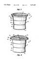
- FIG. 1is a perspective view of a container in accordance with a first principal embodiment of the invention
- FIG. 2is a perspective view of the container illustrated in FIG. 1 but with a cap applied thereto;
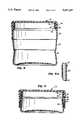
- FIG. 3is a cross section of the container illustrated in FIG. 1;
- FIG. 4is a cross section of the container illustrated in FIG. 2, but in the collapsed condition
- FIG. 5is a partial section view illustrating the manner of connection of the cap and container shown in FIG. 2;
- FIG. 6is a partial cross section showing a manner of attachment between a cap and a container in accordance with a modified version of the embodiment illustrated in FIGS. 1-5;
- FIG. 7is a partial cross section showing a manner of attachment between a cap and a container in accordance with another modified version of the embodiment illustrated in FIGS. 1-5;
- FIG. 8is a side section of another modified version of the embodiment illustrated in FIGS. 1-5;
- FIG. 8Ais a partial section of a variation of the embodiment disclosed in FIG. 8;
- FIG. 9is a side section view of the container illustrated in FIG. 8 but in a collapsed position
- FIG. 10is a side section of a container in accordance with a second principal embodiment of the invention.
- FIG. 11is a side section of the container illustrated in FIG. 10 but in the collapsed position
- FIG. 12is a side section of a container in accordance with a third principal embodiment of the invention.
- FIG. 13is a side section of a container illustrated in FIG. 12, but in the collapsed position.
- an extrusion/blow molded container 10in accordance with the first principal embodiment of the invention generally includes a bottom wall 12 and a peripheral side wall 14 extending generally upwardly from the bottom wall 12.
- the containermay be made of low density polyethylene (LDPE), polypropylene or other suitable plastic material.
- LDPElow density polyethylene
- the side wallis generally circular (when viewed in cross sections taken through the container) but it will be appreciated that the container may have other suitable shapes as well.
- the peripheral side wallterminates at an open upper end 16.
- the peripheral side wall 14 in this exemplary embodimentis formed to include three axial portions including an upper portion 18, an intermediate portion 20 and a lower portion 22.
- the upper and intermediate portions 18 and 20have generally similar axial lengths, while the lower portion 22 has a somewhat greater axial length for a reason described further below.
- An exemplary thickness for side wall portions 18 and 22may be, for example, in the range of about 25 to 60 mil and preferably about 45 mil.
- the bottom wall 12may be substantially thicker if desired.
- the intermediate side wall portion 20may have a thickness between about 2 and 12 mil and preferably about 8 mil.
- the ratio between the thickness of each of the upper and lower side wall portions to the thickness of the intermediate side wall portionshould be at least 3.75 to 1 and preferably about 5 to 1. These ratios are significant in that the absolute thickness values may change depending on container diameter, axial length and hence, volumetric capacity.
- the uppermost end of the container side wall 14includes an annular rim adapted to receive a removable cap or lid, and the thickness of this rim area may be the same or greater than the upper side wall portions. While the upper and lower side wall portions 18 and 22 are flexible, they are relatively rigid as compared to the much thinner intermediate portion 20. This arrangement permits easy collapse, extension and re-collapse of the container in a manner described in more detail below.
- the three described side wall portions 18, 20 and 22are separated by a pair of transitional steps 24, 26 which may comprise radially inwardly directed tucks or indentations which result primarily by the changes in wall thickness at each interface between adjacent side wall portions. These steps facilitate the telescoping of the lower side wall portion 22 into the upper portion 18, as well as the complete reverse folding of the intermediate side wall portion 20 relative to lower side wall portion 22.
- the overall configuration of the peripheral side wallalso contributes to the ease with which the container may be collapsed and extended.
- the upper peripheral side wall portion 18is substantially cylindrical, i.e., of substantially constant diameter.
- the lower peripheral side wall portion 22is tapered in the opposite direction, i.e., the diameter of the lower peripheral side wall portion increases substantially uniformly in the downward direction.
- This configurationis particularly advantageous in that by applying axially compressive forces on the top and bottom of the container, the lower intermediate portion 22 will readily move upwardly toward the upper peripheral side wall portion 18 while causing the intermediate peripheral side wall portion 20 to form a single reverse fold in the manner best seen in FIG. 4.
- the above described side wall configurationestablishes a significant difference in diameters as between the upper side wall portion 18 and the uppermost end of the lower side wall portion 22 (i.e., the smallest diameter of the lower side wall portion). This difference is determined by the degree of taper of the intermediate side wall portion 20, which, in turn, is determined by the maximum and minimum diameters of that portion of the side wall. Exemplary dimensions relating to side wall portion 20 are provided below for containers of varying volumetric capacity.
- the thickness of the upper side wall portion 18must be subtracted from the values given above. It is preferred that these clearances be in the range of from about 0.187 to 0.5 inch, depending on container size, and wall thickness dimensions. By this arrangement, friction resistance as the lower side wall section telescopes into the upper side wall portion (as well as the reverse movement during extension) is minimized. In fact, as best seen in FIG. 4, neither the lower side wall portion 22 nor the intermediate portion 20 are in radial contact with the interior surface of the upper side wall portion 18 when the container is collapsed.
- the tapered lower side wall portion(the upper diameter of which is controlled by the degree of taper of the intermediate side wall portion 20) performs a threefold function of 1) permitting the lower side wall portion to telescope easily into the upper side wall portion 18; 2) providing good stability for the container in a design which would otherwise tend to decrease stability through increasing diameter reductions toward the lower end of the container; and 3) providing a readily accessible gripping point for the user to exert pushing and pulling forces at opposite ends of the container.
- the open upper end 16 of the container 10is formed with a radially outwardly extending shoulder 28 joined to the upper edge of the upper peripheral side wall portion 18.
- the shoulder 28joins with a substantially inverted L-shaped rim 30 comprising a substantially vertical stem portion 32 and a radial flange 34 terminating at an outer peripheral edge 36 to thereby form an annular cap or lid receiving rim.
- the shoulder 28, vertical stem 32 and radial flange 34may be of generally the same or greater thickness as the upper and lower side wall portions 18 and 22, but may vary somewhat depending on how the upper end of the container is formed, i.e., blown along with the side wall or compression formed.
- An associated cap 38 in this first principal embodimentincludes a center disc area 40 including a peripheral, upstanding hollow rib 42, and a depending skirt 44 which has a substantially inverted U-shape.
- the skirtincludes an inner annular skirt portion 46 and a radially outer annular skirt portion 48, connected by an annular, horizontal web 60.
- the outer annular skirt portion 48terminates at an outwardly angled gripping edge 52 which may extend completely (or only partially) about the cap 38.
- the outer annular skirt 48is also provided with an inwardly directed annular projection or lug 54 below and substantially adjacent the web 50.
- the cap 38is pressed onto the container such that the lug 54 snaps over the peripheral edge 36 of the container rim 30.
- Thismay be accomplished by pressing one portion of the cap 38 onto the container 10 and then progressively applying a compressive force (between the cap and the container rim) about the periphery of the container 10 until the cap 38 is fully and securely attached to the container.
- the inner annular skirt portion 46engages the interior of the vertical stem portion 32, substantially continuously about the container, and is preferably in radial compression therewith.
- the relative rigidity of the upper container rim 30 and the compressive engagement between the inner annular skirt portion 46 and the vertical portion 32 of the container riminsures secure attachment of the cap 38 to the container 10. By this arrangement, the cap 38 will not become dislodged from the container 10 as a result of flexing of the container side wall, or upon impact from accidental dropping, etc.
- a modified version of this first embodimentincludes a cap 38 of the screw-on type. More specifically, the open upper end 16' of the container 10' is formed with a radially outwardly extending shoulder 28' joined to the upper edge of the upper peripheral side wall portion 18' The shoulder 28' joins with a substantially vertical annular stem 32' provided with screw threads 62 about the exterior surface thereof.
- the cap 38'includes a center disc area 40' including a peripheral hollow rib 42', and a depending skirt 44' which again has a substantially inverted U-shape.
- the skirt portionincludes an inner annular skirt portion 46' and a radially outer annular skirt portion 48' connected by a horizontal annular web 50'.
- the web 50'has a radial width which is substantially the same as the wall thickness of stem 32' to provide flush engagement between the inner and outer skirt portions 46', 48' and the stem 32'.
- the outer annular skirt portion 48'terminates at an outwardly angled gripping edge 52' which, as in the previously described embodiment, may extend completely about the cap.
- the outer annular skirt 48'is provided with screw threads 64 on its interior surface which are adapted to cooperate with the screw threads 62 provided on the exterior surface of the vertical stem 32'.
- the cap 38'may be screwed onto the container 10' in the conventional fashion, and the inner annular skirt portion 46' will engage the interior surface of the stem 32' to reinforce the same and prevent dislodgement of the cap 38' in substantially the same manner as the inner depending skirt portion 46' of the earlier described embodiment.
- FIG. 7another version of the first principal embodiment is shown.
- the container rimcomprises simply a radially outward web or shoulder 28" and an upward and slightly outwardly tapered extension 30".
- Cap 38"is formed with inner and outer depending skirts 46" and 48" which form a groove which may be pressed onto the stem 32" in a relatively tight frictional engagement.
- this embodimentis similar to the embodiment illustrated in FIG. 6, but the screw threads have been omitted in favor of a sliding type friction fit.
- annular rim at the open upper end of the containerincludes a radially inwardly and upwardly tapered shoulder 68 and a vertically extending stem 70 provided with screw threads 72 for threadably receiving a cap 74.
- the cooperation between the cap inner and outer skirt portions 76, 78 and the stem 70remains as previously described.
- the outer annular skirt 78lies substantially radially flush with the upper peripheral side wall portion 80, thus presenting a smooth transition from cap 74 to upper side wall portion.
- the container configuration including the intermediate side wall portion and lower side wall portion, and the various dimensions thereofare otherwise similar to the previously described versions and therefore need not be further discussed.
- FIG. 8AAn alternative upper side wall design is shown in FIG. 8A where the upper side wall portion 80' extends substantially uniformly from the intermediate side wall portion 82 to the exterior screw thread 72'.
- the cap in this versionwill, of course, extend radially beyond the upper side wall portion 80'.
- the upper peripheral side wall portion 86is formed with a radially outwardly extending hollow rib 88 which includes oppositely tapered portions 90, 92 and an outermost substantially vertical portion 94.
- This hollow rib 88is located intermediate the upper and lower ends of the upper peripheral side wall portion 86. Incorporation of the rib 88 is particularly advantageous in that it provides a convenient gripping point for the user for purposes of both collapsing and extending the container.
- the side wall configurationis such that the upper side wall portion 86 easily accommodates the lower peripheral side wall portion 96 and the intermediate peripheral side wall portion 98 in the collapsed position without interference, in the same manner as in the previously described embodiment.
- FIGS. 12 and 13a third principal embodiment of the invention is illustrated, wherein the upper peripheral side wall portion 100 is reconfigured to include an upwardly and outwardly tapered portion 102 which is joined to a radially inwardly tapered portion 104.
- Surface 102joins to the upright annular rim 106, also provided with external screw threads as previously described.
- the tapered surface 102 of the upper peripheral side wall portion 100provides a good gripping surface for the user to facilitate collapse and extension of the container between the extended position illustrated in FIG. 12 and the collapsed position illustrated in FIG. 13.
- the configuration of the upper peripheral side wall portion 100leaves more than enough axial and radial space to accommodate the lower peripheral side wall portion 108 and the intermediate peripheral side wall portion 110 in the collapsed position.
- the intermediate and lower side wall portions 110, 108, respectivelyare substantially identical to the previously described embodiments.
- a containermay be shipped empty from a manufacturer for filling with foodstuffs or other material at another location.
- the containermay also be sold to consumers empty as a storage container for foodstuffs and/or other materials.
- the containeris particularly advantageous in that it may be collapsed and efficiently stored during shipping and between use.
Landscapes
- Engineering & Computer Science (AREA)
- Mechanical Engineering (AREA)
- Health & Medical Sciences (AREA)
- Ceramic Engineering (AREA)
- Epidemiology (AREA)
- Life Sciences & Earth Sciences (AREA)
- Animal Behavior & Ethology (AREA)
- General Health & Medical Sciences (AREA)
- Public Health (AREA)
- Veterinary Medicine (AREA)
- Containers Having Bodies Formed In One Piece (AREA)
- Closures For Containers (AREA)
Abstract
Description
______________________________________ A. 11 oz. container Max. Dia.: 2.757" Min. Dia.: 2.260" Angle of taper (from vertical): 5.85° Radial clearance: about .248" B. 16 oz. container Max. Dia.: 3.021" Min. Dia.: 2.508" Angle of taper: 5.42° Radial clearance: .256" C. 32 oz. container Max. Dia.: 4.056" Min. Dia.: 3.399" Angle of taper: 6.7° Radial clearance: .328" D. 64 oz. container Max. Dia.: 4.75" Min. Dia.: 4.052" Angle of taper: 5.12° Radial clearance: .349" ______________________________________
Claims (25)
Priority Applications (13)
| Application Number | Priority Date | Filing Date | Title |
|---|---|---|---|
| US08/047,185US5417337A (en) | 1991-11-12 | 1993-04-16 | Reusable and re-collapsible container and associated cap |
| TW82103345ATW254908B (en) | 1993-04-16 | 1993-04-29 | |
| US08/134,656US5549213A (en) | 1991-11-12 | 1993-10-12 | Reusable re-collapsible container and resealable cap |
| US08/227,545US5392941A (en) | 1991-11-12 | 1994-04-14 | Reusable and re-collapsible container and associated cap |
| CA 2160344CA2160344A1 (en) | 1993-04-16 | 1994-04-14 | Improved reusable and re-collapsible container and associated cap |
| CN94192301ACN1124944A (en) | 1993-04-16 | 1994-04-14 | Reusable and refoldable container and its lid |
| AU66330/94AAU6633094A (en) | 1993-04-16 | 1994-04-14 | Improved reusable and re-collapsible container and associated cap |
| EP94914151AEP0694010A4 (en) | 1993-04-16 | 1994-04-14 | Improved reusable and re-collapsible container and associated cap |
| PCT/US1994/004066WO1994024002A1 (en) | 1993-04-16 | 1994-04-14 | Improved reusable and re-collapsible container and associated cap |
| JP52342094AJPH09500851A (en) | 1993-04-16 | 1994-04-14 | Improved reusable, collapsible container and associated cap |
| US08/243,108US5711445A (en) | 1991-11-12 | 1994-05-16 | Collapsible urine container |
| US08/365,404US5575398A (en) | 1991-11-12 | 1994-12-28 | Reusable and re-collapsible container and associated cap |
| US08/365,408US5533638A (en) | 1991-11-12 | 1994-12-28 | Reusable and re-collapsible container and associated cap |
Applications Claiming Priority (4)
| Application Number | Priority Date | Filing Date | Title |
|---|---|---|---|
| US07/789,838US5226551A (en) | 1991-11-12 | 1991-11-12 | Reusable and re-collapsible container |
| PCT/US1993/000399WO1994016957A1 (en) | 1991-11-12 | 1993-01-21 | Reusable and re-collapsible container and associated cap |
| US1212293A | 1993-02-01 | 1993-02-01 | |
| US08/047,185US5417337A (en) | 1991-11-12 | 1993-04-16 | Reusable and re-collapsible container and associated cap |
Related Parent Applications (1)
| Application Number | Title | Priority Date | Filing Date |
|---|---|---|---|
| US1212293AContinuation-In-Part | 1991-11-12 | 1993-02-01 |
Related Child Applications (5)
| Application Number | Title | Priority Date | Filing Date |
|---|---|---|---|
| US29007106Continuation-In-Part | 1993-04-16 | ||
| US08/134,656Continuation-In-PartUS5549213A (en) | 1991-11-12 | 1993-10-12 | Reusable re-collapsible container and resealable cap |
| US08/227,545Continuation-In-PartUS5392941A (en) | 1991-11-12 | 1994-04-14 | Reusable and re-collapsible container and associated cap |
| US08/243,108Continuation-In-PartUS5711445A (en) | 1991-11-12 | 1994-05-16 | Collapsible urine container |
| US08/365,404ContinuationUS5575398A (en) | 1991-11-12 | 1994-12-28 | Reusable and re-collapsible container and associated cap |
Publications (1)
| Publication Number | Publication Date |
|---|---|
| US5417337Atrue US5417337A (en) | 1995-05-23 |
Family
ID=21947520
Family Applications (4)
| Application Number | Title | Priority Date | Filing Date |
|---|---|---|---|
| US08/047,185Expired - LifetimeUS5417337A (en) | 1991-11-12 | 1993-04-16 | Reusable and re-collapsible container and associated cap |
| US08/227,545Expired - LifetimeUS5392941A (en) | 1991-11-12 | 1994-04-14 | Reusable and re-collapsible container and associated cap |
| US08/365,404Expired - LifetimeUS5575398A (en) | 1991-11-12 | 1994-12-28 | Reusable and re-collapsible container and associated cap |
| US08/365,408Expired - LifetimeUS5533638A (en) | 1991-11-12 | 1994-12-28 | Reusable and re-collapsible container and associated cap |
Family Applications After (3)
| Application Number | Title | Priority Date | Filing Date |
|---|---|---|---|
| US08/227,545Expired - LifetimeUS5392941A (en) | 1991-11-12 | 1994-04-14 | Reusable and re-collapsible container and associated cap |
| US08/365,404Expired - LifetimeUS5575398A (en) | 1991-11-12 | 1994-12-28 | Reusable and re-collapsible container and associated cap |
| US08/365,408Expired - LifetimeUS5533638A (en) | 1991-11-12 | 1994-12-28 | Reusable and re-collapsible container and associated cap |
Country Status (8)
| Country | Link |
|---|---|
| US (4) | US5417337A (en) |
| EP (1) | EP0694010A4 (en) |
| JP (1) | JPH09500851A (en) |
| CN (1) | CN1124944A (en) |
| AU (1) | AU6633094A (en) |
| CA (1) | CA2160344A1 (en) |
| TW (1) | TW254908B (en) |
| WO (1) | WO1994024002A1 (en) |
Cited By (41)
| Publication number | Priority date | Publication date | Assignee | Title |
|---|---|---|---|---|
| US5562518A (en)* | 1995-07-28 | 1996-10-08 | Estrada; Luis I. | Telescopic pinata |
| USD383680S (en)* | 1996-03-12 | 1997-09-16 | Robbins Iii Edward S | Portion of a container |
| USD385194S (en)* | 1994-07-12 | 1997-10-21 | Robbins Iii Edward S | Side walls for a container |
| USD388701S (en) | 1997-03-31 | 1998-01-06 | Mattel, Inc. | Container for malleable play material |
| US5717144A (en)* | 1996-05-29 | 1998-02-10 | Edward S. Robbins, III | Collapsible container test fixture |
| WO1998030461A1 (en)* | 1997-01-09 | 1998-07-16 | Flotool Corporation | Stackable containers with removable cover members |
| US5868273A (en)* | 1996-10-11 | 1999-02-09 | Dart Industries Inc. | Canister with pressure resistant sealing lid |
| US5900293A (en)* | 1996-12-26 | 1999-05-04 | S. C. Johnson Home Storage Inc. | Collapsible, monolayer microwaveable container |
| US6116440A (en)* | 1996-11-01 | 2000-09-12 | Colgate - Palmolive Company | Resealable thermoformed container |
| US20050127074A1 (en)* | 2003-12-16 | 2005-06-16 | David Kusuma | Collapsible container |
| US20050258271A1 (en)* | 2004-05-18 | 2005-11-24 | Kosmyna Michael J | Disposable paint cup |
| US20060219725A1 (en)* | 2005-03-18 | 2006-10-05 | Jay Ferro | Multimode distribution container |
| US20060261074A1 (en)* | 2005-05-23 | 2006-11-23 | Nguyen Thuan T | Disposable baby diaper container |
| US20070131712A1 (en)* | 2004-08-26 | 2007-06-14 | Susan Pottish | Apparatus and method for open thread, reusable, no-waste collapsible tube dispensers with control ribs and/or detent |
| US20070241029A1 (en)* | 2004-06-01 | 2007-10-18 | Kosmyna Michael J | Antistatic paint cup |
| US20080141519A1 (en)* | 2004-06-10 | 2008-06-19 | Kosmyna Michael J | Fluid supply assembly |
| US20080142544A1 (en)* | 2004-08-26 | 2008-06-19 | Susan Pottish | Apparatus and method for open thread, reusable, no-waste collapsible tube dispensers |
| US20080230462A1 (en)* | 2007-03-22 | 2008-09-25 | Progressive International Corp. | Collapsible colander & bowl |
| WO2008143617A1 (en)* | 2007-05-22 | 2008-11-27 | Pottish, Susan | Apparatus and method for reusable, no-waste collapsible tube dispensers with control ribs and/or detent, and cap closure |
| US7665672B2 (en) | 2004-01-16 | 2010-02-23 | Illinois Tool Works Inc. | Antistatic paint cup |
| US7744011B2 (en) | 2004-01-16 | 2010-06-29 | Illinois Tool Works Inc. | Antistatic paint cup |
| US7757972B2 (en) | 2004-06-03 | 2010-07-20 | Illinois Tool Works Inc. | Conversion adapter for a fluid supply assembly |
| US20100203199A1 (en)* | 2005-03-18 | 2010-08-12 | Jay Ferro | Packaged Salad |
| USD625154S1 (en) | 2010-02-09 | 2010-10-12 | Progressive International Corporation | Colander |
| USD651476S1 (en) | 2011-02-05 | 2012-01-03 | Progressive International Corporation | Collapsible produce keeper |
| US20120074174A1 (en)* | 2010-08-25 | 2012-03-29 | Birgit Leisen Pollack | Container with Elevating Inner Wall |
| USD669318S1 (en) | 2012-01-26 | 2012-10-23 | Progressive International Corporation | Collapsible container |
| US20130020276A1 (en)* | 2011-07-22 | 2013-01-24 | Craig Allen Madaus | Segmented Collapsible Container |
| USD731260S1 (en) | 2014-01-30 | 2015-06-09 | Progressive International Corporation | Collapsible colander |
| USD731261S1 (en) | 2014-02-03 | 2015-06-09 | Progressive International Corporation | Collapsible over the sink colander |
| USD731862S1 (en) | 2014-01-30 | 2015-06-16 | Progessive International Corporation | Collapsible colander |
| USD732354S1 (en) | 2014-01-30 | 2015-06-23 | Progressive International Corporation | Collapsible colander |
| US9079685B2 (en)* | 2012-08-31 | 2015-07-14 | Wilshire Industries, Llc | Collapsible food container |
| USD746640S1 (en) | 2014-01-31 | 2016-01-05 | Progressive International Corporation | Collapsible storage bowl |
| US20160096662A1 (en)* | 2014-10-06 | 2016-04-07 | Power Source And Associates Corp. | Paper cup cover structure device |
| USD754495S1 (en) | 2014-09-25 | 2016-04-26 | Progressive International Corporation | Colander |
| US9370198B2 (en) | 2013-08-30 | 2016-06-21 | Container Innovations LLC | Deformable container and dispensing machine |
| US9427136B2 (en) | 2014-04-22 | 2016-08-30 | Progressive International Corporation | Collapsible dish drainer |
| USD766530S1 (en) | 2015-02-04 | 2016-09-13 | Progressive International Corporation | Collapsible dish drainer |
| USD895372S1 (en) | 2019-05-20 | 2020-09-08 | Yeti Coolers, Llc | Bowl |
| US11849739B1 (en) | 2019-08-15 | 2023-12-26 | Container Innovations LLC | Collapsible, deformable container and dispensing apparatus |
Families Citing this family (106)
| Publication number | Priority date | Publication date | Assignee | Title |
|---|---|---|---|---|
| US5417337A (en)* | 1991-11-12 | 1995-05-23 | Robbins, Iii; Edward S. | Reusable and re-collapsible container and associated cap |
| AU1739995A (en)* | 1994-03-10 | 1995-09-25 | Dowbrands Inc. | Collapsible, microwavable container |
| AU4750996A (en)* | 1995-02-10 | 1996-08-27 | Dowbrands Inc. | Collapsible, microwavable container |
| US5860556A (en)* | 1996-04-10 | 1999-01-19 | Robbins, Iii; Edward S. | Collapsible storage container |
| GB2333085B (en)* | 1998-01-07 | 2002-04-03 | Dorothy Jones | Portable container |
| US5911338A (en)* | 1998-04-16 | 1999-06-15 | Miller; Lee D. | Adjustable container |
| DE19835346A1 (en)* | 1998-08-05 | 2000-02-10 | Boehringer Ingelheim Pharma | Two-part capsule for pharmaceutical preparations for powder inhalers |
| FR2788041B1 (en)* | 1998-12-31 | 2001-02-16 | Michel Alain Vieville | PACKAGING WITH INSTANT PYRAMIDAL SHAPING BY PRE-FOLDING |
| US6315151B1 (en) | 2000-01-11 | 2001-11-13 | The Procter & Gamble Co. | Collapsible container and method of making |
| US6360886B1 (en) | 2000-03-13 | 2002-03-26 | Kerr Corporation | Capsule for use in preparing a dental amalgam |
| US6145474A (en)* | 2000-05-24 | 2000-11-14 | Lemkin; Jack | Adjustable animal feeder assembly with storage capability |
| US6276547B1 (en) | 2000-06-09 | 2001-08-21 | Thomas M. Petryna | Food containers with detachable and discardable sections |
| IL140026A0 (en)* | 2000-11-30 | 2002-02-10 | Rachel Kibbutz Ramat | Container for packaging and dispensing a substance |
| US6898899B2 (en)* | 2000-12-08 | 2005-05-31 | Wanda M. Weder | Floral container with accordion folded upper portion |
| DE20106406U1 (en)* | 2001-04-12 | 2002-08-22 | Sulzer Chemtech Ag, Winterthur | Closure for a two-component cartridge |
| US6789393B2 (en) | 2002-02-11 | 2004-09-14 | S.C. Johnson Home Storage, Inc. | Container with pressure relief and lid and method of manufacture therefor |
| CN100333972C (en)* | 2002-08-28 | 2007-08-29 | 株式会社吉野工业所 | Synthetic resin made bottle body |
| US7063231B2 (en)* | 2003-06-06 | 2006-06-20 | S. C. Johnson Home Storage, Inc. | Container including a bowl and a lid each having interfitting lips |
| DE10347378A1 (en)* | 2003-10-07 | 2005-05-12 | Huhtamaki Alf Zweigniederlassu | container |
| PL207809B1 (en)* | 2003-11-20 | 2011-02-28 | Invento Społka Z Ograniczoną Odpowiedzialnością | Blank mould for making plastic containers, particularly for storing foodstuffs |
| IL165341A (en)* | 2003-12-16 | 2010-05-31 | Dart Ind Inc | Collapsible container |
| US7086549B2 (en)* | 2004-01-16 | 2006-08-08 | Illinois Tool Works Inc. | Fluid supply assembly |
| US8066136B2 (en) | 2004-04-13 | 2011-11-29 | S.C. Johnson Home Storage, Inc. | Collapsible storage device |
| US8146773B2 (en) | 2004-04-13 | 2012-04-03 | S.C. Johnson & Son, Inc. | Collapsible storage device |
| US7631799B2 (en) | 2004-04-13 | 2009-12-15 | S.C. Johnson Home Storage, Inc. | Container and blank for making the same |
| US7854370B2 (en) | 2004-04-13 | 2010-12-21 | S.C. Johnson Home Storage, Inc. | Collapsible storage device |
| US8033411B2 (en) | 2004-04-13 | 2011-10-11 | S.C. Johnson Home Storage, Inc. | Collapsible storage device |
| US8146763B2 (en) | 2004-04-13 | 2012-04-03 | S.C. Johnson Home Storage, Inc. | Collapsible storage device |
| CA2563072A1 (en) | 2004-04-13 | 2005-10-27 | S. C. Johnson Home Storage, Inc. | Collapsible storage device and method of making the same |
| IL162656A0 (en)* | 2004-06-21 | 2005-11-20 | Hamafteach Hamistovev Ltd | Fluid container |
| DE102005001332A1 (en)* | 2005-01-11 | 2006-07-20 | Boehringer Ingelheim Pharma Gmbh & Co. Kg | Two-piece capsule with pre-closure for holding pharmaceutical preparations for powder inhalers |
| US20060275519A1 (en)* | 2005-05-12 | 2006-12-07 | Dengler Brian S | Plastic tote of cedar-filled material |
| US20070007297A1 (en)* | 2005-05-16 | 2007-01-11 | Li Kwong F | Sealable container |
| US20060255053A1 (en)* | 2005-05-16 | 2006-11-16 | Empire Industrial Corp. | Sealable container |
| US20060277994A1 (en)* | 2005-06-10 | 2006-12-14 | Progressive International Corp. | Invertible measuring cup |
| GB2427555A (en)* | 2005-06-25 | 2007-01-03 | Vacsax Ltd | Medical suction disposal system liner |
| USD545137S1 (en) | 2005-09-23 | 2007-06-26 | Rubbermaid Incorporated | Collapsible storage container |
| US9745085B2 (en)* | 2005-12-12 | 2017-08-29 | Mark Pawlowski | Apparatus, system and method for changing a volume |
| EP1818106A1 (en)* | 2006-02-11 | 2007-08-15 | J. Wagner GmbH | Spray gun |
| NL1031955C2 (en)* | 2006-03-09 | 2007-09-11 | Weasy Pack Internat Ltd | Portion packaging and semi-liquid product. |
| TW200823116A (en)* | 2006-11-17 | 2008-06-01 | Yao-Sin Liao | Air enclosure with independent double-layer air chambers |
| USD571614S1 (en) | 2007-02-23 | 2008-06-24 | Progressive International Corporation | Collapsible bowl |
| US7712625B2 (en)* | 2007-11-02 | 2010-05-11 | Ann Mary Alger | Cooling coaster for beverage container |
| NL2002206C2 (en)* | 2007-11-17 | 2015-01-15 | Rudolphus Johannes Adrianus Maria Cornelissen | HOLDER FOR PAINT. |
| USD582218S1 (en) | 2008-01-31 | 2008-12-09 | Progressive International Corporation | Collapsible bowl |
| USD580799S1 (en) | 2008-01-31 | 2008-11-18 | Progressive International Corporation | Collapsible measuring cup |
| USD584110S1 (en) | 2008-02-01 | 2009-01-06 | Progressive International Corporation | Collapsible bowl with lid |
| ES1067648Y (en)* | 2008-04-09 | 2008-09-01 | Sp Berner Plastic Group Sl | COLLAPSABLE CONTAINER FOR DOMESTIC USE. |
| USD610902S1 (en)* | 2008-07-29 | 2010-03-02 | Allison Janet Walker | Container |
| WO2010063152A1 (en)* | 2008-12-03 | 2010-06-10 | Zhang Jinde | Foldable plate made of silicon rubber with iron frame for roasting angel cake |
| US9835367B2 (en)* | 2008-12-11 | 2017-12-05 | M & C Innovations, Llc | Cooler having removable wheel assembly |
| USD611769S1 (en) | 2009-01-08 | 2010-03-16 | Progressive International Corporation | Collapsible bowl |
| US8434171B2 (en)* | 2009-04-09 | 2013-05-07 | Free 2 Go Producs | Commode seat for a rollator |
| USD604120S1 (en) | 2009-04-14 | 2009-11-17 | Progressive International Corporation | Collapsible bowl with lid |
| US20110163092A1 (en)* | 2010-01-04 | 2011-07-07 | James Scott Hacsi | Collapsible Container And Method Of Forming And Using A Collapsible Container |
| US8403327B2 (en)* | 2010-02-14 | 2013-03-26 | Mattel, Inc. | Collapsible game |
| US20150291309A1 (en)* | 2010-04-12 | 2015-10-15 | Rob Roy McGregor | Collapsible container |
| US20110248040A1 (en)* | 2010-04-12 | 2011-10-13 | 6916783 Canada Inc. | Collapsible container |
| TW201136808A (en)* | 2010-04-20 | 2011-11-01 | Ricco Engineering Internat Inc | Folding bucket structure |
| USD668148S1 (en)* | 2010-09-21 | 2012-10-02 | Devon Sory | Collapsible container cap |
| JP5625682B2 (en)* | 2010-09-27 | 2014-11-19 | 株式会社柏木モールド | Ice container |
| USD662819S1 (en)* | 2010-10-29 | 2012-07-03 | Smart Products Scandinavia Ab | Insect protection device |
| USD646592S1 (en) | 2011-02-05 | 2011-10-11 | Progressive International Corporation | Snap-fit measuring cup |
| USD646989S1 (en) | 2011-02-05 | 2011-10-18 | Progressive International Corporation | Snap-fit measuring spoon |
| US8806935B2 (en) | 2011-02-08 | 2014-08-19 | Progressive International Corporation | Snap-fit measuring container |
| GB2506553B (en)* | 2011-06-13 | 2017-05-03 | Mercy Medical Res Inst | Sanitary disposable unisex urine device |
| USD652745S1 (en)* | 2011-07-20 | 2012-01-24 | Robinson Home Products Inc. | Liquid measuring cup |
| USD706134S1 (en)* | 2011-10-06 | 2014-06-03 | Devon Sory | Telescoping container cap |
| US9237795B2 (en) | 2011-12-06 | 2016-01-19 | John Rey Hollis | Collapsible beverage cup |
| US9044082B2 (en) | 2012-04-20 | 2015-06-02 | Dart Industries Inc. | Collapsible container |
| DK2890428T3 (en) | 2012-08-31 | 2019-06-11 | Sanofi Aventis Deutschland | MEDICAL DEVICE WITH FASTENING HOUSE |
| TW201416293A (en)* | 2012-10-19 | 2014-05-01 | Rui-Hong Duan | Foldable silicone container structure |
| US9211975B2 (en) | 2012-10-26 | 2015-12-15 | Edward S. Robbins, III | Compactable jug and handle |
| US20140311940A1 (en)* | 2013-04-17 | 2014-10-23 | Jonathan Braveman | Closeable silicon container |
| AU2014262656B2 (en) | 2013-05-08 | 2018-08-09 | Graco Minnesota Inc. | Paint can adapter for handheld spray device |
| US20140367418A1 (en)* | 2013-06-16 | 2014-12-18 | Mark McNitt | Portable Beverage Dispensing System |
| US9119507B2 (en)* | 2013-08-11 | 2015-09-01 | Urban Tumbler LLC | Collapsible travel tumbler |
| US10105014B2 (en)* | 2014-02-04 | 2018-10-23 | Progressive International Corporation | Collapsible food keeper |
| US9975661B2 (en)* | 2014-02-04 | 2018-05-22 | Progressive International Corporation | Collapsible produce keeper |
| JP6291383B2 (en)* | 2014-08-07 | 2018-03-14 | 株式会社マーナ | Mouth cap for beverage can |
| CN104210742B (en)* | 2014-08-28 | 2016-09-14 | 航天精工股份有限公司 | A kind of lid for Glass capacity bottle sealing |
| US9694938B2 (en) | 2014-12-04 | 2017-07-04 | Design Fold Llc | Collapsible receptacle |
| GB201615043D0 (en)* | 2016-09-05 | 2016-10-19 | Formabowl Llp | Improved container |
| EP3573593B1 (en) | 2017-01-27 | 2023-08-30 | The Procter & Gamble Company | Compositions in the form of dissolvable solid structures |
| CN107416311A (en)* | 2017-07-17 | 2017-12-01 | 黄健阳 | A kind of scalable plastic bottle |
| CN107487505A (en)* | 2017-08-31 | 2017-12-19 | 邬惠林 | A kind of silica gel stretches water bottle |
| US20190119000A1 (en)* | 2017-10-20 | 2019-04-25 | Sam Tung Tsui | Collapsible Shape-Retaining Containers |
| US10492500B1 (en)* | 2018-08-31 | 2019-12-03 | Samuel Siwak | Dispensing baked good container assembly and method |
| EP3656416B1 (en)* | 2018-11-21 | 2023-12-06 | SHL Medical AG | Stand for medicament delivery device, and system comprising stand and medicament delivery device |
| US10611564B1 (en) | 2019-01-02 | 2020-04-07 | Dooli Products, LLC | Height adjustable waste disposal device with bag-grabbing membrane |
| US11172754B2 (en) | 2019-03-06 | 2021-11-16 | Design Fold Llc | Collapsible vessel |
| BR112021023244A2 (en) | 2019-06-28 | 2022-01-04 | Procter & Gamble | Soluble solid fibrous articles containing anionic surfactants |
| WO2021003492A1 (en) | 2019-07-03 | 2021-01-07 | The Procter & Gamble Company | Fibrous structures containing cationic surfactants and soluble acids |
| CN110451074B (en)* | 2019-08-14 | 2020-12-18 | 嘉兴华竹电子有限公司 | Water conservancy construction project material management system |
| DE102019122799B3 (en) | 2019-08-26 | 2020-04-09 | Steffen Baumann und Sutepan Ganendiran compacToys GbR (vertretungsberechtigte Gesellschafter: Steffen Baumann, 79199 Kirchzarten und Sutepan Ganendiran, 79232 March) | Improved sand toys |
| CN114727933B (en) | 2019-11-20 | 2024-03-08 | 宝洁公司 | Porous dissolvable solid structure |
| US11008162B1 (en) | 2020-02-03 | 2021-05-18 | Dooli Products, LLC | Baby and adult-safe waste container with bag handling odor control assembly |
| USD895918S1 (en) | 2020-02-07 | 2020-09-08 | Dooli Products, LLC | Vertically oriented container with a lid |
| USD895919S1 (en) | 2020-02-07 | 2020-09-08 | Dooli Products, LLC | Container with a lid |
| US12227336B2 (en)* | 2020-05-28 | 2025-02-18 | Frontier Cooperative | Flexible walled container |
| USD940506S1 (en) | 2020-06-25 | 2022-01-11 | Hydaway, LLC | Collapsible tumbler |
| AU2020207877B2 (en)* | 2020-07-24 | 2023-01-05 | B.Box For Kids Developments Pty Ltd | A dispensable food container |
| US11759039B1 (en)* | 2021-01-14 | 2023-09-19 | Jacqueline Cintron | Adjustable portable cup holder |
| CN116369557B (en)* | 2023-02-23 | 2024-11-08 | 广西壮族自治区蚕业技术推广站 | Foldable micro-pressure processing equipment for instant prefabricated food |
| USD1084757S1 (en) | 2023-06-12 | 2025-07-22 | Sven Johnson | Insulator |
| US20250295092A1 (en)* | 2024-03-19 | 2025-09-25 | Joshua Brazeal | Telescopic pet water container for cup holders |
Citations (43)
| Publication number | Priority date | Publication date | Assignee | Title |
|---|---|---|---|---|
| US1048935A (en)* | 1912-09-25 | 1912-12-31 | John F Brady | Drinking-cup. |
| FR587701A (en)* | 1923-10-17 | 1925-04-23 | Container for transporting pulverized coal | |
| US2784882A (en)* | 1956-04-12 | 1957-03-12 | Plax Corp | Pleated dispenser |
| US2880902A (en)* | 1957-06-03 | 1959-04-07 | Owsen Peter | Collapsible article |
| US2899110A (en)* | 1959-08-11 | Parker | ||
| US2985915A (en)* | 1958-12-12 | 1961-05-30 | Hedwin Corp | Thermoforming process for thermoplastic sheeting |
| US3143429A (en)* | 1961-10-09 | 1964-08-04 | Pillsbury Co | Collapsible disposable container and nursing unit |
| US3156383A (en)* | 1962-04-05 | 1964-11-10 | Maison Ind Tecnico Chimiche Ne | Expansible single use dispensing container |
| US3220544A (en)* | 1963-04-26 | 1965-11-30 | Walter C Lovell | Packaging and novel container employed therewith |
| US3301293A (en)* | 1964-12-16 | 1967-01-31 | Owens Illinois Inc | Collapsible container |
| DE1301970B (en)* | 1967-11-06 | 1969-08-28 | Genuhn Ullrich | Axially collapsible container |
| US3467283A (en)* | 1968-01-18 | 1969-09-16 | Continental Can Co | Dispensing container with collapsible compartment |
| US3494509A (en)* | 1966-06-13 | 1970-02-10 | John S Mcguire | Variable volume reservoir |
| US3608268A (en)* | 1967-06-07 | 1971-09-28 | Schmith Niels Bay | Method for producing thin-walled,collapsible containers or packages |
| US3707241A (en)* | 1970-04-21 | 1972-12-26 | Sanford Res Co | Plasitc container with threaded mouth strengthening closure means |
| DE2340967A1 (en)* | 1972-09-05 | 1974-03-14 | Sika Ag | CONTAINER WITH LOCKABLE SPOUT |
| US3864771A (en)* | 1972-08-21 | 1975-02-11 | Textron Inc | Deployable load buoyancy support container or shelter system |
| US3875941A (en)* | 1974-04-03 | 1975-04-08 | Medical Dynamics Inc | System for evacuating fluids from the body |
| US3939888A (en)* | 1971-07-14 | 1976-02-24 | Scarnato Thomas J | Hermetically sealable collapsible container |
| US4087024A (en)* | 1976-02-27 | 1978-05-02 | Graber-Rogg, Inc. | Fluid dispenser |
| GB2109247A (en)* | 1981-11-13 | 1983-06-02 | Shen Kuang Hsu | Nursing bottle |
| US4428507A (en)* | 1981-05-19 | 1984-01-31 | Sneider Vincent R | Collapsible container with accordion pleated sidewalls, air vent and swivel valve outlet |
| US4456134A (en)* | 1982-01-22 | 1984-06-26 | Leonard Cooper | Apparatus for containment of carbonated beverages |
| GB2138525A (en)* | 1983-04-22 | 1984-10-24 | Beatrice Foods Co | Pleated tubular connectors |
| US4492313A (en)* | 1984-05-29 | 1985-01-08 | William Touzani | Collapsible bottle |
| US4706829A (en)* | 1986-02-07 | 1987-11-17 | Owens-Illinois Closure Inc. | Liquid containing and dispensing package |
| US4712699A (en)* | 1986-10-02 | 1987-12-15 | Captive Plastics, Inc. | Package employing unique seal |
| WO1988005014A1 (en)* | 1987-01-09 | 1988-07-14 | Ludi Jean Claude | Foldable container for liquids which is self-locking in folded position |
| US4775564A (en)* | 1985-03-11 | 1988-10-04 | The Goodyear Tire & Rubber Company | Collapsible-stable blown container |
| US4805799A (en)* | 1988-03-04 | 1989-02-21 | Robbins Edward S Iii | Container with unitary bladder |
| US4815615A (en)* | 1986-10-22 | 1989-03-28 | Royal Industries (Thailand) Co., Ltd. | Infant feeding system |
| US4844273A (en)* | 1988-09-06 | 1989-07-04 | Sunbeam Plastics Corporation | Closure with enhanced sealing |
| US4846376A (en)* | 1988-02-25 | 1989-07-11 | Ballard Medical Products | Inversion foamer |
| US4865211A (en)* | 1988-03-04 | 1989-09-12 | Hollingsworth Elmont E | Collapsible article |
| US4873100A (en)* | 1987-04-15 | 1989-10-10 | The Procter & Gamble Company | Bistable expandable bottle |
| US4875576A (en)* | 1988-02-05 | 1989-10-24 | Torgrimson Lee A | Mixing kit |
| US4892126A (en)* | 1982-03-01 | 1990-01-09 | Henkel Kommanditgesellschaft Auf Aktien | Threaded dosing cap |
| US4925055A (en)* | 1988-03-04 | 1990-05-15 | Edward S. Robbins, III | Container with unitary bladder and associated dispenser cap |
| US4955493A (en)* | 1989-08-15 | 1990-09-11 | Touzani William N | Collapsible expansible plastic hollow articles in a latchable configuration |
| US4979628A (en)* | 1988-12-22 | 1990-12-25 | Robbins Edward S Iii | Containers having one or more integral annular bands of increased thickness |
| US5002193A (en)* | 1989-08-15 | 1991-03-26 | Touzani William N | Collapsible hollow articles with latching configuration and attached handle |
| DE3937456A1 (en)* | 1989-11-10 | 1991-05-16 | Joerg Kreuzer | Extensible container with closure - has alternating ridges and narrow parts, and can be flattened for storage |
| JPH04102544A (en)* | 1990-08-02 | 1992-04-03 | Hoei Kogyo Kk | Collapsible can |
Family Cites Families (4)
| Publication number | Priority date | Publication date | Assignee | Title |
|---|---|---|---|---|
| US3578415A (en)* | 1969-10-13 | 1971-05-11 | Us Army | Dry hydrogen generator |
| US4930644A (en)* | 1988-12-22 | 1990-06-05 | Robbins Edward S Iii | Thin film container with removable lid and related process |
| US5226551A (en)* | 1991-11-12 | 1993-07-13 | Robbins Edward S Iii | Reusable and re-collapsible container |
| US5417337A (en)* | 1991-11-12 | 1995-05-23 | Robbins, Iii; Edward S. | Reusable and re-collapsible container and associated cap |
- 1993
- 1993-04-16USUS08/047,185patent/US5417337A/ennot_activeExpired - Lifetime
- 1993-04-29TWTW82103345Apatent/TW254908B/zhactive
- 1994
- 1994-04-14CACA 2160344patent/CA2160344A1/ennot_activeAbandoned
- 1994-04-14WOPCT/US1994/004066patent/WO1994024002A1/ennot_activeApplication Discontinuation
- 1994-04-14JPJP52342094Apatent/JPH09500851A/ennot_activeCeased
- 1994-04-14AUAU66330/94Apatent/AU6633094A/ennot_activeAbandoned
- 1994-04-14USUS08/227,545patent/US5392941A/ennot_activeExpired - Lifetime
- 1994-04-14CNCN94192301Apatent/CN1124944A/enactivePending
- 1994-04-14EPEP94914151Apatent/EP0694010A4/ennot_activeWithdrawn
- 1994-12-28USUS08/365,404patent/US5575398A/ennot_activeExpired - Lifetime
- 1994-12-28USUS08/365,408patent/US5533638A/ennot_activeExpired - Lifetime
Patent Citations (43)
| Publication number | Priority date | Publication date | Assignee | Title |
|---|---|---|---|---|
| US2899110A (en)* | 1959-08-11 | Parker | ||
| US1048935A (en)* | 1912-09-25 | 1912-12-31 | John F Brady | Drinking-cup. |
| FR587701A (en)* | 1923-10-17 | 1925-04-23 | Container for transporting pulverized coal | |
| US2784882A (en)* | 1956-04-12 | 1957-03-12 | Plax Corp | Pleated dispenser |
| US2880902A (en)* | 1957-06-03 | 1959-04-07 | Owsen Peter | Collapsible article |
| US2985915A (en)* | 1958-12-12 | 1961-05-30 | Hedwin Corp | Thermoforming process for thermoplastic sheeting |
| US3143429A (en)* | 1961-10-09 | 1964-08-04 | Pillsbury Co | Collapsible disposable container and nursing unit |
| US3156383A (en)* | 1962-04-05 | 1964-11-10 | Maison Ind Tecnico Chimiche Ne | Expansible single use dispensing container |
| US3220544A (en)* | 1963-04-26 | 1965-11-30 | Walter C Lovell | Packaging and novel container employed therewith |
| US3301293A (en)* | 1964-12-16 | 1967-01-31 | Owens Illinois Inc | Collapsible container |
| US3494509A (en)* | 1966-06-13 | 1970-02-10 | John S Mcguire | Variable volume reservoir |
| US3608268A (en)* | 1967-06-07 | 1971-09-28 | Schmith Niels Bay | Method for producing thin-walled,collapsible containers or packages |
| DE1301970B (en)* | 1967-11-06 | 1969-08-28 | Genuhn Ullrich | Axially collapsible container |
| US3467283A (en)* | 1968-01-18 | 1969-09-16 | Continental Can Co | Dispensing container with collapsible compartment |
| US3707241A (en)* | 1970-04-21 | 1972-12-26 | Sanford Res Co | Plasitc container with threaded mouth strengthening closure means |
| US3939888A (en)* | 1971-07-14 | 1976-02-24 | Scarnato Thomas J | Hermetically sealable collapsible container |
| US3864771A (en)* | 1972-08-21 | 1975-02-11 | Textron Inc | Deployable load buoyancy support container or shelter system |
| DE2340967A1 (en)* | 1972-09-05 | 1974-03-14 | Sika Ag | CONTAINER WITH LOCKABLE SPOUT |
| US3875941A (en)* | 1974-04-03 | 1975-04-08 | Medical Dynamics Inc | System for evacuating fluids from the body |
| US4087024A (en)* | 1976-02-27 | 1978-05-02 | Graber-Rogg, Inc. | Fluid dispenser |
| US4428507A (en)* | 1981-05-19 | 1984-01-31 | Sneider Vincent R | Collapsible container with accordion pleated sidewalls, air vent and swivel valve outlet |
| GB2109247A (en)* | 1981-11-13 | 1983-06-02 | Shen Kuang Hsu | Nursing bottle |
| US4456134A (en)* | 1982-01-22 | 1984-06-26 | Leonard Cooper | Apparatus for containment of carbonated beverages |
| US4892126A (en)* | 1982-03-01 | 1990-01-09 | Henkel Kommanditgesellschaft Auf Aktien | Threaded dosing cap |
| GB2138525A (en)* | 1983-04-22 | 1984-10-24 | Beatrice Foods Co | Pleated tubular connectors |
| US4492313A (en)* | 1984-05-29 | 1985-01-08 | William Touzani | Collapsible bottle |
| US4775564A (en)* | 1985-03-11 | 1988-10-04 | The Goodyear Tire & Rubber Company | Collapsible-stable blown container |
| US4706829A (en)* | 1986-02-07 | 1987-11-17 | Owens-Illinois Closure Inc. | Liquid containing and dispensing package |
| US4712699A (en)* | 1986-10-02 | 1987-12-15 | Captive Plastics, Inc. | Package employing unique seal |
| US4815615A (en)* | 1986-10-22 | 1989-03-28 | Royal Industries (Thailand) Co., Ltd. | Infant feeding system |
| WO1988005014A1 (en)* | 1987-01-09 | 1988-07-14 | Ludi Jean Claude | Foldable container for liquids which is self-locking in folded position |
| US4873100A (en)* | 1987-04-15 | 1989-10-10 | The Procter & Gamble Company | Bistable expandable bottle |
| US4875576A (en)* | 1988-02-05 | 1989-10-24 | Torgrimson Lee A | Mixing kit |
| US4846376A (en)* | 1988-02-25 | 1989-07-11 | Ballard Medical Products | Inversion foamer |
| US4865211A (en)* | 1988-03-04 | 1989-09-12 | Hollingsworth Elmont E | Collapsible article |
| US4805799A (en)* | 1988-03-04 | 1989-02-21 | Robbins Edward S Iii | Container with unitary bladder |
| US4925055A (en)* | 1988-03-04 | 1990-05-15 | Edward S. Robbins, III | Container with unitary bladder and associated dispenser cap |
| US4844273A (en)* | 1988-09-06 | 1989-07-04 | Sunbeam Plastics Corporation | Closure with enhanced sealing |
| US4979628A (en)* | 1988-12-22 | 1990-12-25 | Robbins Edward S Iii | Containers having one or more integral annular bands of increased thickness |
| US4955493A (en)* | 1989-08-15 | 1990-09-11 | Touzani William N | Collapsible expansible plastic hollow articles in a latchable configuration |
| US5002193A (en)* | 1989-08-15 | 1991-03-26 | Touzani William N | Collapsible hollow articles with latching configuration and attached handle |
| DE3937456A1 (en)* | 1989-11-10 | 1991-05-16 | Joerg Kreuzer | Extensible container with closure - has alternating ridges and narrow parts, and can be flattened for storage |
| JPH04102544A (en)* | 1990-08-02 | 1992-04-03 | Hoei Kogyo Kk | Collapsible can |
Cited By (58)
| Publication number | Priority date | Publication date | Assignee | Title |
|---|---|---|---|---|
| USD385194S (en)* | 1994-07-12 | 1997-10-21 | Robbins Iii Edward S | Side walls for a container |
| US5562518A (en)* | 1995-07-28 | 1996-10-08 | Estrada; Luis I. | Telescopic pinata |
| USD383680S (en)* | 1996-03-12 | 1997-09-16 | Robbins Iii Edward S | Portion of a container |
| US5717144A (en)* | 1996-05-29 | 1998-02-10 | Edward S. Robbins, III | Collapsible container test fixture |
| US5868273A (en)* | 1996-10-11 | 1999-02-09 | Dart Industries Inc. | Canister with pressure resistant sealing lid |
| US6116440A (en)* | 1996-11-01 | 2000-09-12 | Colgate - Palmolive Company | Resealable thermoformed container |
| US5900293A (en)* | 1996-12-26 | 1999-05-04 | S. C. Johnson Home Storage Inc. | Collapsible, monolayer microwaveable container |
| WO1998030461A1 (en)* | 1997-01-09 | 1998-07-16 | Flotool Corporation | Stackable containers with removable cover members |
| USD388701S (en) | 1997-03-31 | 1998-01-06 | Mattel, Inc. | Container for malleable play material |
| US20050127073A1 (en)* | 2003-12-16 | 2005-06-16 | David Kusuma | Collapsible container |
| US7654402B2 (en) | 2003-12-16 | 2010-02-02 | Dart Industries Inc. | Collapsible container |
| US20050127074A1 (en)* | 2003-12-16 | 2005-06-16 | David Kusuma | Collapsible container |
| US7753289B2 (en) | 2004-01-16 | 2010-07-13 | Illinois Tool Works Inc. | Antistatic paint cup |
| US7744011B2 (en) | 2004-01-16 | 2010-06-29 | Illinois Tool Works Inc. | Antistatic paint cup |
| US7665672B2 (en) | 2004-01-16 | 2010-02-23 | Illinois Tool Works Inc. | Antistatic paint cup |
| US20050258271A1 (en)* | 2004-05-18 | 2005-11-24 | Kosmyna Michael J | Disposable paint cup |
| US7766250B2 (en) | 2004-06-01 | 2010-08-03 | Illinois Tool Works Inc. | Antistatic paint cup |
| US20070241029A1 (en)* | 2004-06-01 | 2007-10-18 | Kosmyna Michael J | Antistatic paint cup |
| US7757972B2 (en) | 2004-06-03 | 2010-07-20 | Illinois Tool Works Inc. | Conversion adapter for a fluid supply assembly |
| US7874323B2 (en) | 2004-06-10 | 2011-01-25 | Illinois Tool Works, Inc. | Fluid supply assembly |
| US20080141519A1 (en)* | 2004-06-10 | 2008-06-19 | Kosmyna Michael J | Fluid supply assembly |
| US20070131712A1 (en)* | 2004-08-26 | 2007-06-14 | Susan Pottish | Apparatus and method for open thread, reusable, no-waste collapsible tube dispensers with control ribs and/or detent |
| US7686187B2 (en)* | 2004-08-26 | 2010-03-30 | Scott V. Anderson | Apparatus and method for open thread, reusable, no-waste collapsible tube dispensers with control ribs and/or detent |
| US20080142544A1 (en)* | 2004-08-26 | 2008-06-19 | Susan Pottish | Apparatus and method for open thread, reusable, no-waste collapsible tube dispensers |
| US20100203199A1 (en)* | 2005-03-18 | 2010-08-12 | Jay Ferro | Packaged Salad |
| US20060219725A1 (en)* | 2005-03-18 | 2006-10-05 | Jay Ferro | Multimode distribution container |
| US20060261074A1 (en)* | 2005-05-23 | 2006-11-23 | Nguyen Thuan T | Disposable baby diaper container |
| US7458480B2 (en)* | 2005-05-23 | 2008-12-02 | Thuan Thien Nguyen | Disposable baby diaper container |
| US8871092B2 (en) | 2007-03-22 | 2014-10-28 | Progressive International Corporation | Collapsible colander and bowl |
| US7678271B2 (en) | 2007-03-22 | 2010-03-16 | Progressive International Corporation | Collapsible colander and bowl |
| US20100170840A1 (en)* | 2007-03-22 | 2010-07-08 | Progressive International Corporation | Collapsible colander & bowl |
| US20080230462A1 (en)* | 2007-03-22 | 2008-09-25 | Progressive International Corp. | Collapsible colander & bowl |
| WO2008143617A1 (en)* | 2007-05-22 | 2008-11-27 | Pottish, Susan | Apparatus and method for reusable, no-waste collapsible tube dispensers with control ribs and/or detent, and cap closure |
| USD625154S1 (en) | 2010-02-09 | 2010-10-12 | Progressive International Corporation | Colander |
| US20120074174A1 (en)* | 2010-08-25 | 2012-03-29 | Birgit Leisen Pollack | Container with Elevating Inner Wall |
| US8627987B2 (en)* | 2010-08-25 | 2014-01-14 | Wisys Technology Foundation | Container with elevating inner wall |
| USD651476S1 (en) | 2011-02-05 | 2012-01-03 | Progressive International Corporation | Collapsible produce keeper |
| US20130020276A1 (en)* | 2011-07-22 | 2013-01-24 | Craig Allen Madaus | Segmented Collapsible Container |
| US8763829B2 (en)* | 2011-07-22 | 2014-07-01 | Craig Allen Madaus | Collapsible container for holding liquids or objects |
| USD669318S1 (en) | 2012-01-26 | 2012-10-23 | Progressive International Corporation | Collapsible container |
| WO2013151581A1 (en)* | 2012-04-05 | 2013-10-10 | Madaus Craig | Segmented collapsible container |
| US11021296B2 (en) | 2012-08-31 | 2021-06-01 | Wilshire Industries, Llc | Collapsible food container |
| US9079685B2 (en)* | 2012-08-31 | 2015-07-14 | Wilshire Industries, Llc | Collapsible food container |
| US10486859B2 (en) | 2012-08-31 | 2019-11-26 | Wilshire Industries, Llc | Collapsible food container |
| US9409677B2 (en) | 2012-08-31 | 2016-08-09 | Wilshire Industries, Llc | Collapsible food container |
| US9370198B2 (en) | 2013-08-30 | 2016-06-21 | Container Innovations LLC | Deformable container and dispensing machine |
| USD731260S1 (en) | 2014-01-30 | 2015-06-09 | Progressive International Corporation | Collapsible colander |
| USD731862S1 (en) | 2014-01-30 | 2015-06-16 | Progessive International Corporation | Collapsible colander |
| USD732354S1 (en) | 2014-01-30 | 2015-06-23 | Progressive International Corporation | Collapsible colander |
| USD746640S1 (en) | 2014-01-31 | 2016-01-05 | Progressive International Corporation | Collapsible storage bowl |
| USD731261S1 (en) | 2014-02-03 | 2015-06-09 | Progressive International Corporation | Collapsible over the sink colander |
| US9427136B2 (en) | 2014-04-22 | 2016-08-30 | Progressive International Corporation | Collapsible dish drainer |
| USD754495S1 (en) | 2014-09-25 | 2016-04-26 | Progressive International Corporation | Colander |
| US20160096662A1 (en)* | 2014-10-06 | 2016-04-07 | Power Source And Associates Corp. | Paper cup cover structure device |
| USD766530S1 (en) | 2015-02-04 | 2016-09-13 | Progressive International Corporation | Collapsible dish drainer |
| USD895372S1 (en) | 2019-05-20 | 2020-09-08 | Yeti Coolers, Llc | Bowl |
| USD931055S1 (en) | 2019-05-20 | 2021-09-21 | Yeti Coolers, Llc | Bowl |
| US11849739B1 (en) | 2019-08-15 | 2023-12-26 | Container Innovations LLC | Collapsible, deformable container and dispensing apparatus |
Also Published As
| Publication number | Publication date |
|---|---|
| WO1994024002A1 (en) | 1994-10-27 |
| US5533638A (en) | 1996-07-09 |
| US5392941A (en) | 1995-02-28 |
| US5575398A (en) | 1996-11-19 |
| EP0694010A1 (en) | 1996-01-31 |
| TW254908B (en) | 1995-08-21 |
| CN1124944A (en) | 1996-06-19 |
| JPH09500851A (en) | 1997-01-28 |
| CA2160344A1 (en) | 1994-10-27 |
| EP0694010A4 (en) | 1997-01-02 |
| AU6633094A (en) | 1994-11-08 |
Similar Documents
| Publication | Publication Date | Title |
|---|---|---|
| US5417337A (en) | Reusable and re-collapsible container and associated cap | |
| US5711445A (en) | Collapsible urine container | |
| US5549213A (en) | Reusable re-collapsible container and resealable cap | |
| US5226551A (en) | Reusable and re-collapsible container | |
| US5860556A (en) | Collapsible storage container | |
| US2090320A (en) | Cocktail shaker | |
| US6598755B1 (en) | Disposable bottle having a gradually collapsible, recovery-free, structure of its side-walls | |
| US3042271A (en) | Container with retractable projectable spout | |
| US7654402B2 (en) | Collapsible container | |
| US4790361A (en) | Collapsible carbonated beverage container | |
| US4706829A (en) | Liquid containing and dispensing package | |
| US2859085A (en) | Cold cream jars | |
| US5295609A (en) | Container with integral straw | |
| WO1993015995A1 (en) | Re-collapsible container with spray head | |
| US20130140211A1 (en) | Nestable collapsible containers | |
| US20070017921A1 (en) | Horizontally expansible and contractible food storage container with Hinged folding cover | |
| US5005726A (en) | Composite container assemblies | |
| EP1182147A2 (en) | Beverage container cap body | |
| US2898014A (en) | Combination extensible and foldable vent and spout for containers | |
| US759976A (en) | Oiler or oil-can. | |
| EP0680443A1 (en) | Reusable and re-collapsible container and associated cap | |
| US1432718A (en) | Paper container | |
| US20240294311A1 (en) | Container Closure with Integral Utensil | |
| JPH04128235U (en) | Container with variable volume |
Legal Events
| Date | Code | Title | Description |
|---|---|---|---|
| STPP | Information on status: patent application and granting procedure in general | Free format text:APPLICATION UNDERGOING PREEXAM PROCESSING | |
| AS | Assignment | Owner name:SOUTHTRUST BANK OF ALABAMA, NATIONAL ASSOCIATION, Free format text:SECURITY INTEREST;ASSIGNORS:E S ROBBINS CORPORATION A CORP. OF ALABAMA;ROBBINS, E.S., III;REEL/FRAME:007384/0316 Effective date:19950101 | |
| CC | Certificate of correction | ||
| AS | Assignment | Owner name:FIRST UNION COMMERCIAL CORPORATION, NORTH CAROLINA Free format text:SECURITY AGREEMENT;ASSIGNORS:E S ROBBINS CORPORATION;ROBBINS, EDWARD S. III;REEL/FRAME:008698/0387 Effective date:19970902 | |
| FEPP | Fee payment procedure | Free format text:PAT HLDR NO LONGER CLAIMS SMALL ENT STAT AS INDIV INVENTOR (ORIGINAL EVENT CODE: LSM1); ENTITY STATUS OF PATENT OWNER: SMALL ENTITY | |
| FPAY | Fee payment | Year of fee payment:4 | |
| FEPP | Fee payment procedure | Free format text:PAT HOLDER CLAIMS SMALL ENTITY STATUS, ENTITY STATUS SET TO SMALL (ORIGINAL EVENT CODE: LTOS); ENTITY STATUS OF PATENT OWNER: SMALL ENTITY | |
| AS | Assignment | Owner name:UNION PLANTERS BANK, NATIONAL ASSOCIATION, ALABAMA Free format text:ASSIGNMENT OF ASSIGNORS INTEREST;ASSIGNORS:ROBBINS, E.S., III;ROBBINS, MARY L.;REEL/FRAME:012852/0225 Effective date:20020417 | |
| FPAY | Fee payment | Year of fee payment:8 | |
| REMI | Maintenance fee reminder mailed | ||
| AS | Assignment | Owner name:UNION PLANTER BANK, NATIONAL ASSOCIATION, ALASKA Free format text:SECURITY AGREEMENT;ASSIGNORS:E.S. ROBBINS CORPORATION;CENTAUR HTP NORTHEAST FENCING SYSTEMS, INC.;ROBBINS, E.S., III;AND OTHERS;REEL/FRAME:014227/0555 Effective date:20020401 | |
| FPAY | Fee payment | Year of fee payment:12 |