US5416293A - Shock sensor including a compound housing and magnetically operated reed switch - Google Patents
Shock sensor including a compound housing and magnetically operated reed switchDownload PDFInfo
- Publication number
- US5416293A US5416293AUS08/292,340US29234094AUS5416293AUS 5416293 AUS5416293 AUS 5416293AUS 29234094 AUS29234094 AUS 29234094AUS 5416293 AUS5416293 AUS 5416293A
- Authority
- US
- United States
- Prior art keywords
- reed switch
- magnet
- housing
- shock sensor
- abutment
- Prior art date
- Legal status (The legal status is an assumption and is not a legal conclusion. Google has not performed a legal analysis and makes no representation as to the accuracy of the status listed.)
- Expired - Fee Related
Links
- 235000014676Phragmites communisNutrition0.000titleclaimsabstractdescription136
- 230000035939shockEffects0.000titleclaimsabstractdescription122
- 150000001875compoundsChemical class0.000title1
- 230000004913activationEffects0.000claimsdescription19
- 230000005291magnetic effectEffects0.000claimsdescription13
- 239000002775capsuleSubstances0.000claimsdescription11
- 239000011521glassSubstances0.000claimsdescription7
- 230000037431insertionEffects0.000claims2
- 238000003780insertionMethods0.000claims2
- 230000005294ferromagnetic effectEffects0.000claims1
- 239000000463materialSubstances0.000claims1
- 238000012360testing methodMethods0.000abstractdescription9
- 230000035945sensitivityEffects0.000abstractdescription7
- 238000004519manufacturing processMethods0.000description10
- 230000001133accelerationEffects0.000description7
- 244000273256Phragmites communisSpecies0.000description6
- 210000005069earsAnatomy0.000description4
- 230000008901benefitEffects0.000description3
- 230000008439repair processEffects0.000description3
- 230000008859changeEffects0.000description2
- 238000010276constructionMethods0.000description2
- 230000007246mechanismEffects0.000description2
- 230000036316preloadEffects0.000description2
- 230000009467reductionEffects0.000description2
- 239000004593EpoxySubstances0.000description1
- 229910000831SteelInorganic materials0.000description1
- 238000004873anchoringMethods0.000description1
- 238000000418atomic force spectrumMethods0.000description1
- 230000006835compressionEffects0.000description1
- 238000007906compressionMethods0.000description1
- 230000003247decreasing effectEffects0.000description1
- 238000001514detection methodMethods0.000description1
- 239000003302ferromagnetic materialSubstances0.000description1
- 238000009434installationMethods0.000description1
- 230000002452interceptive effectEffects0.000description1
- 239000002991molded plasticSubstances0.000description1
- 238000004806packaging method and processMethods0.000description1
- 239000004033plasticSubstances0.000description1
- 230000000717retained effectEffects0.000description1
- 239000000565sealantSubstances0.000description1
- 238000007789sealingMethods0.000description1
- 238000000926separation methodMethods0.000description1
- 238000007493shaping processMethods0.000description1
- 239000010959steelSubstances0.000description1
Images


Classifications
- H—ELECTRICITY
- H01—ELECTRIC ELEMENTS
- H01H—ELECTRIC SWITCHES; RELAYS; SELECTORS; EMERGENCY PROTECTIVE DEVICES
- H01H35/00—Switches operated by change of a physical condition
- H01H35/14—Switches operated by change of acceleration, e.g. by shock or vibration, inertia switch
- H01H35/147—Switches operated by change of acceleration, e.g. by shock or vibration, inertia switch the switch being of the reed switch type
Definitions
- This inventionrelates to shock sensors in general and to shock sensors employing reed switches in particular.
- Shock sensorsemploying reed switches am used in motor vehicles to detect a vehicle collision. When a collision occurs, the shock sensor triggers an electrical circuit for the actuation of safety devices such as inflating air bags, tensioning seat belts, and other similar systems.
- shock sensorstypically employ a reed switch with an acceleration sensing magnet which is biased by a spring away from an activation region of the reed switch such that the reed switch is open when the shock sensor is not subject to acceleration.
- the magnetWhen the vehicle and the shock sensor, which is attached to the vehicle, are subject to a crash-induced acceleration, the magnet acts as an acceleration-sensing mass. The magnet moves relative to the central activation region and exposes the reeds of the switch to a magnetic field, which causes the reeds to mutually attract and close the reed switch.
- U.S. Pat. No. 5,194,706a shock sensor employing end-actuation in a compact package.
- My previously disclosed shock sensorachieves considerable advantages in reduced package size which facilitates placement of the shock sensor within the automobile. Placement of shock sensors may be critical to reliable and effective operation since smaller sensors may be readily placed in effective locations.
- shock sensorsare increasingly in demand.
- Features which can reduce costs in manufacturingare especially desireable.
- a shock sensoris needed which has a reduced part count which is adaptable to machine assembly and which may be readily adapted to accommodate the unique tolerancing variation associated with reed switches.
- the shock sensor of this inventionemploys a housing with two portions.
- the first portion of the housingresiliently engages a reed switch which has staple formed depending leads.
- the housing second portionextends adjacent one end of the reed switch.
- the second portionis a hollow tube which defines a cylindrical shaft with a closed end.
- a bobbincomprised of a central guide bar with two axially spaced radially-extending disks is inserted into the open end.
- a biasing springextends between the closed end and an actuation magnet slidably mounted on the guide bar.
- a reed switch self-test coilis wrapped about the guide bar between the two disks.
- the biasing magnetis separated from the self-test coil by the one of the disks which positions the actuation magnet with respect to the reed switch when it is in its non-actuated position. The magnet thus travels between the disk and the closed end of the housing second portion.
- the shock sensor of this inventionpermits different bobbins and springs to be inserted within a common housing to ensure consistent shock sensor operation despite the reed switch sensitivity.
- the actuation magnetmay be displaced a greater or lesser distance from the reed switch and hence the activation region may be tailored to the attributes of the particular reed switch as determined by testing.
- Biasing springs of common length but of greater or lesser spring constantare also inserted to achieve the desired identical functions with reed switches of varying amp turn requirements for actuation.
- the biasing springis adjusted for each category of reed switches with a given actuation amp turn range by varying the number of touching turns of the actuation spring. Touching turns are turns of the spring which are not displaced laterally from each other and thus impart no resistance to compression of the spring.
- the packaging designachieves significant reduction in piece parts for the individual shock sensor. In addition, the entire family of shock sensors necessary to utilize the majority of the particular manufacturing lot of reed switches may be manufactured with even more significant decrease in part count.
- the first portion of the housinghas a downwardly opening hole adjacent to the end of the tube formed by the second portion and centrally located with respect to the second portion.
- a staple formed reed switchthat is a reed switch having leads bent downwardly in the shape of a staple, is preferably machine-positioned with one leg or lead inserted into the downwardly opening hole. The reed switch may then be swung against a linearly extending resilient beam wherein the downwardly extending lead opposite the one contained in the hole is resiliently held by a retaining feature on the resilient beam.
- shock sensor of this inventionAnother feature of the shock sensor of this invention is that the actuation magnet is strongly attracted to the reed switch lead which goes down the downwardly opening hole. This attraction force offsets the spring force which provides design parameters which allow an increase in dwell or minimum dwell and allow the possibility of designing a latching shock sensor.
- the self-test coilwhile providing the ability to test the shock sensor by moving the actuation magnet due to an induced magnetic field in the coil also serves two additional functions.
- the first of theseis the ability to unlatch a shock sensor which has been designed to latch.
- the second functionis the ability to adaptively change the characteristics of the reed switch.
- a number of shock sensors, and possibly other types of sensorsare positioned around the vehicle to detect vehicle impacts on various quadrants. If over the life of the vehicle, one or more sensors becomes inoperative, repair is very difficult because the functioning of the sensor depends on its being properly positioned and mounted to respond as designed.
- the preferred mode of repairmay be to design the system to adaptively reconfigure to compensate for the loss of one sensor by adjustments in the sensitivities of other sensors so that the shock sensing system as a whole is fault tolerant and continues to operate effectively despite loss of functionality of some of its components.
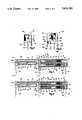
- FIG. 1is an exploded, isometric view of the shock sensor of this invention.
- FIG. 2is an isometric view, partly cut away, of the shock sensor of FIG. 1.
- FIG. 3is an end view of the shock sensor of FIG. 7 taken along line 3-3.
- FIG. 4is an end view of an alternative embodiment shock sensor employing two reed switches.
- FIG. 5is a cross-sectional view of the shock sensor of FIG. 7 taken along section line 5-5.
- FIG. 6is a cross-sectional view of the alternative embodiment shock sensor employing two reed switches of FIG. 4 taken through the first housing section.
- FIG. 7is a cross-sectional view of the shock sensor of FIG. 1 shown in the non-actuated position.
- FIG. 8is a cross-sectional view of the shock sensor of FIG. 1 shown in the actuated position.
- FIG. 9is a graphical view showing the forces on the actuation magnet of a shock sensor of this invention, the graph being juxtaposed with a fragmentary cross-sectional view of a reed switch having an aligned x-axis.
- FIG. 10is a graphical view of the forces on the actuation magnet of a shock sensor of this invention in which the magnet and spring are selected so that the reed switch will latch in the closed position.
- the graphis juxtaposed with a fragmentary cross-sectional view of the reed switch having an x-axis.
- FIGS. 1, 2, 7 and 8an improved end actuated shock sensor 20 is shown in FIGS. 1, 2, 7 and 8.
- the shock sensorhas a housing 22 which is divided into a first portion 24 which holds and positions the reed switch 26, and a second portion 28 which contains an actuation magnet 30.
- the actuation magnet 30has a central bore 32 which is slidably engaged on the axially extending guide bar 34 of a molded plastic bobbin 36.
- the bobbin 36is inserted into a hollow tube 38 which is defined by the second portion 28 of the shock sensor housing 22.
- the second portionhas a closed end 40 which terminates the hollow tube 38 and is adjacent to the housing first portion 24 and also spaced from a first end 42 of the reed switch 26.
- a biasing spring 44is positioned about the guide bar 34 and extends between the closed end 40 of the housing second portion and a radially extending lip 46 in the central bore 32 of the magnet 30.
- the closed end 40 of the housing second portionforms a first abutment for the magnet 30, and the disk 50 forms a second abutment.
- the bobbin 36has a first radially extending disk 50 which is formed axisymmetrically about the bobbin guide bar 34.
- a second radially extending disk 52is also formed on the guide bar 34 and is axially spaced from the first disk away from the reed switch 26 in the assembled shock sensor 20.
- a self-test coil 54is wound on to a portion 56 of the guide bar 34 between the first disk 50 and the second disk 52.
- the second disk 52has a first slot 58 and a second slot 60 which pass the ends 62 of the coil 54.
- the coil ends 62are soldered or welded to extending coil leads 64.
- the bobbin 36When the shock sensor 20 is assembled, as shown in FIG. 1, the bobbin 36 is centered and positioned within the hollow bore 38 of the housing second portion 28 of the shock sensor 20.
- the bobbin 36is radially positioned by the first and second radial disks 50, 52 which engage the inside surface 61 of the hollow tube 38.
- the guide bar 34has a conical end 74 which aids in aligning the guide bar along the axis 68 of the shock sensor 20 by engaging with a nubbin 70 which protrudes from the closed end 40 of the housing second portion 28 within the tube 38.
- the nubbinis smaller in diameter than the internal bore 32 of the magnet 30 and has a concave surface 72 which faces toward the bobbin disks and which engages with the conical end 74 of the guide bar 34.
- the bobbin 36is positively retained within the hollow tube 38 by two tapered ears 76 which extend from the base 73 of the bobbin 36.
- the tapered ears 76engage in openings 78 in the second portion 28 of the housing 22.
- the housing 22is constructed of resilient plastic and the walls 80 of the housing 22 allow the passage of the ears 76 by resiliently deforming outwardly until the ears protrude through the openings 78 in the walls 80, thus positively locking the bobbin 36 within the hollow tube 38 of the housing second portion 28.
- the reed switch 26is formed of a glass capsule 82 which is fused about two reeds 84.
- the glass capsule 82has a first end 42 adjacent to the housing second portion 28 and a second end 43 distal from the housing second portion 28.
- the reeds 84have contact areas 86 which when brought into engagement, as shown in FIG. 8, close an electrical circuit between a first lead 88 and a second lead 90.
- the leads 88, 90are bent downwardly at approximately 90 degrees from the axis 68 of the shock sensor 20 and reed switch 26.
- the so-called staple formed leads 88, 90position the reed switch 26 on the first portion 24 of the housing 22.
- a downwardly opening hole 94is defined at the juncture 92 between the housing first portion 24 and the housing second portion 28.
- the first lead 88extends through the hole 94.
- the reed switchis assembled to the housing 22 by inserting the first lead 88 into the hole 94 with the reed switch 22 initially positioned approximately forty-five degrees from the axis 68 of the reed switch 20.
- the reed switch 26is then swung into axial alignment so that the first lead 88 is engaged in a frontwardly facing notch 96 shown in FIG. 5.
- the first housing portionhas a slim resilient beam 102, shown in FIGS. 1 and 5, which extends the length of the reed switch from the juncture 92 to a downwardly depending member 100.
- the beam 102is flexible to allow it to be deformed upwardly so that the second lead 90 can be positioned beneath the depending member 100. Once the beam is released the second lead 90 is engaged within a slot 98 formed in the depending member 100.
- the shock sensor 20has relatively few individual piece parts. These individual parts are self-aligning and positioning on and within the housing 22, thus facilitating machine assembly of the components.
- Legs 104extend downwardly from the housing 22 to position the shock sensor 20 above a circuit board (not shown), thus allowing the reed switch 20 to be mounted above other electrical components which are mounted to the circuit board.
- FIGS. 7 and 8The operation of the reed switch 20 is shown and illustrated in FIGS. 7 and 8.
- the first end 106 of the magnet 30is disposed against the second abutment 108 formed by the first disk 50 of the bobbin.
- the magnet 30, functioning as an acceleration sensing massmoves towards the first end 42 of the reed switch 26.
- the magnet 30will be halted in its travel when the second end 110 of the magnet engages against the first abutment defined by the housing end 40. This travel of the magnet 30 brings it into an activation position, in which the magnetic field produced by the magnet causes the reed switch reeds 84 to mutually attract so that the contact surfaces 86 close the circuit between the leads 88 and 90.
- the shock sensor 20is not only readily assembled by machine, but may use reed switches of standard lead length and configuration.
- the shock sensor 20has a compact package which is achieved by employing end activation of the reed switch such as disclosed in my previous patent, U.S. Pat. No. 5,194,706, the disclosure of which is hereby incorporated by reference herein.
- the first lead 88is preferably formed of a ferromagnetic material such as steel to create a magnetic attractive force between the magnet 30 and the lead 88.
- the shock sensor 20utilizes the force of attraction between the magnet 30 and the first lead 88 to control the characteristics of the force-distance curve 112 shown in FIG. 9.
- the y-axisis delineated in grams force positive and grams force negative, with grams force positive being the force which holds the activation magnet 30 away from the first end 42 of the reed switch 26.
- Curve 114is the spring force curve and illustrates how the force applied to the magnet 30 by the spring increases linearly as the magnet is moved along the x-axis towards the reed switch 26.
- Lower curve 116is a plot of increasing magnetic attraction between the lead 88 and the actuation magnet 30 as the actuation magnet 30 moves along the x-axis toward the first end 42 of the reed switch 26.
- the design of the shock sensor 20takes advantage of the attractive force between a staple formed reed switch lead and the actuation magnet to add an additional parameter which may be utilized in the design of shock sensors advantageously to improve the design and to introduce new capabilities and functions.
- FIG. 9illustrates how the combination of the spring force represented by curve 114 and the magnetic attraction force represented by curve 116 combine to provide a force-distance curve 112 which achieves additional dwell time by reducing the return force acting on the magnet 30 between the activation point and the stop point.
- the pre-load position shown in FIG. 9corresponds to the magnet 30 being positioned with its rear face 106 against the second abutment 108.
- the stop locationcorresponds to the magnet 30 having its second face 110 positioned adjacent to the first abutment 40.
- Activationtakes place as the magnet 30 moves from the second abutment 108 to the first abutment 40.
- the dwell time of the activation for the shock sensor 20may be extended.
- Extended dwell timesare highly desirable in improving the reliability of the operation of equipment driven by the shock sensor 20. If an activation time of a given length can be depended on, the overlap of contact closures of the shock sensor 20 and the contact closure of another shock sensor that may be activated in parallel to the shock sensor 20 in the crash sensing system, the overlap between sensors becomes greater, and thus the triggering of the safety devices based on both shock sensors becomes possible.
- the shock sensor 20may be configured so that upon activation the magnet will latch with the reed switch in the activated position.
- a spring selected to have, for example, the spring activation curve 118, shown in FIG. 10,has a restorative force at the magnet stop position which is less than the attractive force between the magnet and the lead 88 at the same position, as indicated by the magnet attraction curve 120.
- the net force on the magnet at any positionis illustrated by the force-distance curve 122.
- the net negative force at the stop positionmeans that the magnet actuating the reed switch latches in the closed position.
- the shock sensor 20may thus, by employing a properly configured spring 44 and magnet, provide a latching switch without the additional coil and current loop required in conventional latching reed switches.
- the shaded regions 117 in FIG. 9 and 119 in FIG. 10represent the tolerance bands on the force-distance curves produced by variation in the individual components which make up the shock sensor 20. As illustrated in FIG. 10, the stop distance is chosen so that no permissible tolerance variation will prevent the reed switch of FIG. 10 from latching. In a similar way, the reed switch of FIG. 9 is configured so that latching will not occur within the permissible tolerance variations for the reed switch of FIG. 9.
- the coil 54can be used to achieve self-testing of the shock sensor 20 as disclosed in my earlier Rencau U.S. Pat. No. 4,980,526 et al.
- the coilmay be used to perform two additional functions in the shock sensor 20. First, it may be used to unlatch the shock sensor 20 when it is configured as in FIG. 10. Secondly, the coil the may be used to adjust the actuation parameters of the shock sensor 20 so adjusting its sensitivity. This can be critical in applications in automobiles for actuating passive passenger restraint devices such as airbags and seatbelt locks. Because the placement of the shock sensor can be critical to the proper function in the event of a crash, it will often prove infeasible to repair or replace a faulty sensor.
- adjustments in the sensitivity of the remaining sensorsmay be accomplished by supplying a biasing magnetic field to the coil 54 which will change the sensitivity of a shock sensor 20 allowing a crash detection system which continues to be functional despite the loss of one or more individual sensors.
- any batch of reed switchesas manufactured, the individual switches have a relatively wide distribution in the magnetic field strength required to close the switch.
- the partsam normally tested to determine the required field strengths for actuation, typically measured in amp turns, and the switches are sorted into groups of with a narrow range of amp turn requirements for activation.
- the required production volume of a reed switch for employment in a typical automobile projectmay be several hundred thousand to a million or more.
- Each carrequires multiple shock sensors employing one or more reed switches each. A year's production of a car is often in the hundreds of thousands.
- the shock sensor 20 of this inventionmay be modified to function with reed switches of varying amp turn requirements by modifying only two components.
- the first component which may be modifiedis the bobbin.
- the second bobbin disk 52is relocated relative to placement changes of the first bobbin disk 50 and second abutment 108.
- the second component which must be modifiedis the spring 44.
- the spring 44 in its uncompressed statehas a number of touching coils 124.
- the spring characteristicsmay be adjusted without adjusting either the gauge of the wire forming the spring or the length of the wire forming the spring.
- the shock sensor 20can be designed to provide similar activation characteristics when employed with reed switches of varying amp turn activation requirements.
- a production run of shock sensors with consistent performance characteristicsmay thus be manufactured using substantially all the reed switches from a production batch by sorting the reed switches into tolerance ranges and then assembling the reed switches within each group with a bobbin and spring of appropriate characteristics.
- the shock sensor 20also may be hermetically sealed by placing a sealant 126 such as an epoxy about the base 73 as shown in FIG. 8.
- a sealant 126such as an epoxy
- FIGS. 4 and 6An alternative embodiment shock sensor 220 is shown in FIGS. 4 and 6.
- the shock sensor 220employs two reed switches 226 mounted on the housing 222 which is divided into a first portion 224 and a second portion 228.
- the closed end 240 of the hollow tube (not shown)is indicated on FIGS. 4 and 6 and shows the relative size of the activation magnet (not shown) and shock sensing mechanism.
- the shock sensor 220is otherwise similar in configuration and actuation mechanism to the shock sensor 20.
- shock sensor 220provides a compact, cost-effective package which is made feasible by the overall configuration, including the end activation of a shock sensor 220.
- shock sensor 220has legs 204 which terminate in barbs 205.
- the barbsmay be advantageously used in some circumstances where it is desirable to lock the shock sensor into slots on a circuit board to prevent its movement before the shock sensor 220 is soldered to the circuit board. Additionally, where no coil is employed, the barbs 205 provide additional stability in positioning and anchoring the shock sensor on a circuit board.
- the shock sensor 222has leads 288 which fit into slob 296 which facilitate the machine loading of reed switches from first one side and then the other of the shock sensor 222.
- a relief notch 128may advantageously be formed on the second portion 28 of the housing to allow the glass capsule portion forming the first end of the reed switch to enter into engagement with slot 96 without coming into interfering engagements with the housing 28.
- shock sensor 20can be employed with reed switches of varying configuration including those that are normally closed or employ a single reed. It should also be understood that the reed switch while capable of being hermetically sealed will function satisfactorily in many circumstances without hermetic sealing.
Landscapes
- Switches Operated By Changes In Physical Conditions (AREA)
Abstract
Description
Claims (17)
Priority Applications (4)
| Application Number | Priority Date | Filing Date | Title |
|---|---|---|---|
| US08/292,340US5416293A (en) | 1994-08-17 | 1994-08-17 | Shock sensor including a compound housing and magnetically operated reed switch |
| EP95305668AEP0697597B1 (en) | 1994-08-17 | 1995-08-15 | Shock sensor including a compound housing and magnetically operated reed switch |
| DE69505754TDE69505754T2 (en) | 1994-08-17 | 1995-08-15 | Shock sensor with assembled housing and magnetically operated reed switch |
| JP7209782AJP2634579B2 (en) | 1994-08-17 | 1995-08-17 | Impact sensor with composite housing and magnetically actuated reed switch |
Applications Claiming Priority (1)
| Application Number | Priority Date | Filing Date | Title |
|---|---|---|---|
| US08/292,340US5416293A (en) | 1994-08-17 | 1994-08-17 | Shock sensor including a compound housing and magnetically operated reed switch |
Publications (1)
| Publication Number | Publication Date |
|---|---|
| US5416293Atrue US5416293A (en) | 1995-05-16 |
Family
ID=23124230
Family Applications (1)
| Application Number | Title | Priority Date | Filing Date |
|---|---|---|---|
| US08/292,340Expired - Fee RelatedUS5416293A (en) | 1994-08-17 | 1994-08-17 | Shock sensor including a compound housing and magnetically operated reed switch |
Country Status (4)
| Country | Link |
|---|---|
| US (1) | US5416293A (en) |
| EP (1) | EP0697597B1 (en) |
| JP (1) | JP2634579B2 (en) |
| DE (1) | DE69505754T2 (en) |
Cited By (14)
| Publication number | Priority date | Publication date | Assignee | Title |
|---|---|---|---|---|
| US5675134A (en)* | 1992-05-25 | 1997-10-07 | Siemens Aktiengesellschaft | Traffic accident detecting sensor for a passenger protection system in a vehicle |
| US5770792A (en)* | 1995-10-27 | 1998-06-23 | Nippon Aleph Corporation | Shock sensors |
| US5939961A (en)* | 1995-06-06 | 1999-08-17 | Robot Coupe (S.N.C) | Electric safety locking device |
| US5955714A (en)* | 1998-05-20 | 1999-09-21 | Breed Technologies, Inc. | Roll-over shunt sensor |
| US6002091A (en)* | 1998-11-18 | 1999-12-14 | Breed Automotive Technology, Inc. | Bi-directional shock sensor employing reed switch |
| US6018130A (en)* | 1998-05-20 | 2000-01-25 | Breed Automotive Technology, Inc. | Roll-over sensor with pendulum mounted magnet |
| US6142007A (en)* | 1997-06-11 | 2000-11-07 | Nippon Aleph Corporation | Shock sensor |
| US6274829B1 (en)* | 2000-03-02 | 2001-08-14 | Honda Of America Manufacturing, Inc. | Wireless inductive coupled switch |
| US6335498B1 (en)* | 2001-05-18 | 2002-01-01 | Bread Automotive Technology, Inc. | Shock sensor employing a spring coil for self-test |
| US20040201290A1 (en)* | 2001-06-19 | 2004-10-14 | Ahmad Razzaghi | Electromagnetic power device |
| US20070100527A1 (en)* | 2005-10-31 | 2007-05-03 | Ford Global Technologies, Llc | Method for operating a pre-crash sensing system with protruding contact sensor |
| US20070115104A1 (en)* | 2005-11-21 | 2007-05-24 | Denso Corporation | Collision detection system and protection system using the same |
| US20090088921A1 (en)* | 2007-09-28 | 2009-04-02 | Korea Advanced Institute Of Science And Technology | Module for detecting a vehicle crash and an airbag deploying system including the same |
| US11040682B1 (en) | 2016-03-21 | 2021-06-22 | Paradigm Research and Engineering, LLC | Blast detection and safety deployment system and method for using the same |
Families Citing this family (1)
| Publication number | Priority date | Publication date | Assignee | Title |
|---|---|---|---|---|
| KR20170011592A (en)* | 2015-07-23 | 2017-02-02 | 주식회사 현대포리텍 | A brake level sensor for the oil reserver |
Citations (30)
| Publication number | Priority date | Publication date | Assignee | Title |
|---|---|---|---|---|
| US3247343A (en)* | 1963-10-22 | 1966-04-19 | American Mach & Foundry | Magnetically operated switches |
| DE1287186B (en)* | 1963-04-18 | 1969-01-16 | Lehner Fernsprech Signal | Electric pendulum switch |
| US3465271A (en)* | 1968-04-02 | 1969-09-02 | Illinois Tool Works | Magnetic switching device |
| US3559124A (en)* | 1969-02-19 | 1971-01-26 | Hermetic Switch Inc | Magnetically actuated reed switches |
| US3588401A (en)* | 1969-08-14 | 1971-06-28 | Eaton Yale & Towne | Inverted pendulum oscillating controller impact switch with decreasing returning forces acting upon the pendulum as it pivots from its normal position |
| FR2161233A5 (en)* | 1971-11-18 | 1973-07-06 | Dav | |
| US3795780A (en)* | 1972-08-11 | 1974-03-05 | Garrett Corp | Acceleration sensor with magnetic operated, oscillating reed switch |
| US3804999A (en)* | 1971-07-12 | 1974-04-16 | Motor Wheel Corp | Anti-skid vehicle braking system |
| US3853199A (en)* | 1971-11-30 | 1974-12-10 | Nissan Motor | Collision sensor for fender bumper operated vehicle safety device |
| US4016535A (en)* | 1975-12-15 | 1977-04-05 | Sheller-Globe Corporation | Tilt alarm for tractor vehicle or the like |
| US4117430A (en)* | 1977-03-14 | 1978-09-26 | Burroughs Corporation | Keyboard switch |
| US4453148A (en)* | 1983-02-24 | 1984-06-05 | Norakidze Georgy G | Key switch |
| US4456897A (en)* | 1981-06-08 | 1984-06-26 | Sentrol, Inc. | Plunger-operated switch unit |
| US4463312A (en)* | 1981-04-13 | 1984-07-31 | Aisin Seiki Kabushiki Kaisha | Speed sensor device |
| US4484041A (en)* | 1982-05-03 | 1984-11-20 | Daimler-Benz Aktiengesellschaft | Magnetically actuated electric switch |
| US4518835A (en)* | 1982-09-01 | 1985-05-21 | General Instrument Corp. | Force responsive switch |
| US4700163A (en)* | 1986-09-29 | 1987-10-13 | Security Technologies | Removable magnetic switch security system for buildings |
| US4705922A (en)* | 1986-06-10 | 1987-11-10 | Hengstler Bauelemente Gmbh | Relay for the operation of a belt tightener or tensioner for automobile safety belts |
| US4737751A (en)* | 1987-02-17 | 1988-04-12 | George Risk | Robbery alarm switch |
| US4820888A (en)* | 1988-05-16 | 1989-04-11 | Shields Larry E | Tilt switch replacing mercury switches |
| US4877927A (en)* | 1989-04-06 | 1989-10-31 | Hamlin Incorporated | Extended dwell shock sensing device |
| US4965416A (en)* | 1988-05-11 | 1990-10-23 | W. Gunther Gmbh | Acceleration and deceleration sensor |
| US4980526A (en)* | 1989-04-06 | 1990-12-25 | Hamlin Incorporated | Device and method for testing acceleration shock sensors |
| US4987276A (en)* | 1988-09-09 | 1991-01-22 | Audi Ag | Deceleration switch |
| US5128641A (en)* | 1987-06-08 | 1992-07-07 | Hermetic Switch, Inc. | Magnetic switches |
| US5194706A (en)* | 1991-08-14 | 1993-03-16 | Hamlin, Inc. | Shock sensor with a magnetically operated reed switch |
| US5212357A (en)* | 1991-08-14 | 1993-05-18 | Hamlin, Inc. | Extended minimum dwell shock sensor |
| US5237134A (en)* | 1989-12-06 | 1993-08-17 | Breed Automotive Technology, Inc. | Gas damped crash sensor |
| US5248861A (en)* | 1989-08-11 | 1993-09-28 | Tdk Corporation | Acceleration sensor |
| US5293523A (en)* | 1993-06-25 | 1994-03-08 | Hermetic Switch, Inc. | Unidirectional magnetic proximity detector |
Family Cites Families (1)
| Publication number | Priority date | Publication date | Assignee | Title |
|---|---|---|---|---|
| DE9205276U1 (en)* | 1992-04-16 | 1993-08-19 | W. Günther GmbH, 90431 Nürnberg | Position and acceleration sensitive switch |
- 1994
- 1994-08-17USUS08/292,340patent/US5416293A/ennot_activeExpired - Fee Related
- 1995
- 1995-08-15EPEP95305668Apatent/EP0697597B1/ennot_activeExpired - Lifetime
- 1995-08-15DEDE69505754Tpatent/DE69505754T2/ennot_activeExpired - Fee Related
- 1995-08-17JPJP7209782Apatent/JP2634579B2/ennot_activeExpired - Fee Related
Patent Citations (30)
| Publication number | Priority date | Publication date | Assignee | Title |
|---|---|---|---|---|
| DE1287186B (en)* | 1963-04-18 | 1969-01-16 | Lehner Fernsprech Signal | Electric pendulum switch |
| US3247343A (en)* | 1963-10-22 | 1966-04-19 | American Mach & Foundry | Magnetically operated switches |
| US3465271A (en)* | 1968-04-02 | 1969-09-02 | Illinois Tool Works | Magnetic switching device |
| US3559124A (en)* | 1969-02-19 | 1971-01-26 | Hermetic Switch Inc | Magnetically actuated reed switches |
| US3588401A (en)* | 1969-08-14 | 1971-06-28 | Eaton Yale & Towne | Inverted pendulum oscillating controller impact switch with decreasing returning forces acting upon the pendulum as it pivots from its normal position |
| US3804999A (en)* | 1971-07-12 | 1974-04-16 | Motor Wheel Corp | Anti-skid vehicle braking system |
| FR2161233A5 (en)* | 1971-11-18 | 1973-07-06 | Dav | |
| US3853199A (en)* | 1971-11-30 | 1974-12-10 | Nissan Motor | Collision sensor for fender bumper operated vehicle safety device |
| US3795780A (en)* | 1972-08-11 | 1974-03-05 | Garrett Corp | Acceleration sensor with magnetic operated, oscillating reed switch |
| US4016535A (en)* | 1975-12-15 | 1977-04-05 | Sheller-Globe Corporation | Tilt alarm for tractor vehicle or the like |
| US4117430A (en)* | 1977-03-14 | 1978-09-26 | Burroughs Corporation | Keyboard switch |
| US4463312A (en)* | 1981-04-13 | 1984-07-31 | Aisin Seiki Kabushiki Kaisha | Speed sensor device |
| US4456897A (en)* | 1981-06-08 | 1984-06-26 | Sentrol, Inc. | Plunger-operated switch unit |
| US4484041A (en)* | 1982-05-03 | 1984-11-20 | Daimler-Benz Aktiengesellschaft | Magnetically actuated electric switch |
| US4518835A (en)* | 1982-09-01 | 1985-05-21 | General Instrument Corp. | Force responsive switch |
| US4453148A (en)* | 1983-02-24 | 1984-06-05 | Norakidze Georgy G | Key switch |
| US4705922A (en)* | 1986-06-10 | 1987-11-10 | Hengstler Bauelemente Gmbh | Relay for the operation of a belt tightener or tensioner for automobile safety belts |
| US4700163A (en)* | 1986-09-29 | 1987-10-13 | Security Technologies | Removable magnetic switch security system for buildings |
| US4737751A (en)* | 1987-02-17 | 1988-04-12 | George Risk | Robbery alarm switch |
| US5128641A (en)* | 1987-06-08 | 1992-07-07 | Hermetic Switch, Inc. | Magnetic switches |
| US4965416A (en)* | 1988-05-11 | 1990-10-23 | W. Gunther Gmbh | Acceleration and deceleration sensor |
| US4820888A (en)* | 1988-05-16 | 1989-04-11 | Shields Larry E | Tilt switch replacing mercury switches |
| US4987276A (en)* | 1988-09-09 | 1991-01-22 | Audi Ag | Deceleration switch |
| US4980526A (en)* | 1989-04-06 | 1990-12-25 | Hamlin Incorporated | Device and method for testing acceleration shock sensors |
| US4877927A (en)* | 1989-04-06 | 1989-10-31 | Hamlin Incorporated | Extended dwell shock sensing device |
| US5248861A (en)* | 1989-08-11 | 1993-09-28 | Tdk Corporation | Acceleration sensor |
| US5237134A (en)* | 1989-12-06 | 1993-08-17 | Breed Automotive Technology, Inc. | Gas damped crash sensor |
| US5194706A (en)* | 1991-08-14 | 1993-03-16 | Hamlin, Inc. | Shock sensor with a magnetically operated reed switch |
| US5212357A (en)* | 1991-08-14 | 1993-05-18 | Hamlin, Inc. | Extended minimum dwell shock sensor |
| US5293523A (en)* | 1993-06-25 | 1994-03-08 | Hermetic Switch, Inc. | Unidirectional magnetic proximity detector |
Cited By (18)
| Publication number | Priority date | Publication date | Assignee | Title |
|---|---|---|---|---|
| US5675134A (en)* | 1992-05-25 | 1997-10-07 | Siemens Aktiengesellschaft | Traffic accident detecting sensor for a passenger protection system in a vehicle |
| US5939961A (en)* | 1995-06-06 | 1999-08-17 | Robot Coupe (S.N.C) | Electric safety locking device |
| US5770792A (en)* | 1995-10-27 | 1998-06-23 | Nippon Aleph Corporation | Shock sensors |
| US6142007A (en)* | 1997-06-11 | 2000-11-07 | Nippon Aleph Corporation | Shock sensor |
| US5955714A (en)* | 1998-05-20 | 1999-09-21 | Breed Technologies, Inc. | Roll-over shunt sensor |
| US6018130A (en)* | 1998-05-20 | 2000-01-25 | Breed Automotive Technology, Inc. | Roll-over sensor with pendulum mounted magnet |
| US6002091A (en)* | 1998-11-18 | 1999-12-14 | Breed Automotive Technology, Inc. | Bi-directional shock sensor employing reed switch |
| US6274829B1 (en)* | 2000-03-02 | 2001-08-14 | Honda Of America Manufacturing, Inc. | Wireless inductive coupled switch |
| US6335498B1 (en)* | 2001-05-18 | 2002-01-01 | Bread Automotive Technology, Inc. | Shock sensor employing a spring coil for self-test |
| EP1258896A3 (en)* | 2001-05-18 | 2004-04-28 | Breed Automotive Technology, Inc. | Shock sensor employing a coil spring for self-test |
| US20040201290A1 (en)* | 2001-06-19 | 2004-10-14 | Ahmad Razzaghi | Electromagnetic power device |
| US7064461B2 (en)* | 2001-06-19 | 2006-06-20 | Ahmad Razzaghi | Electromagnetic power device |
| US20070100527A1 (en)* | 2005-10-31 | 2007-05-03 | Ford Global Technologies, Llc | Method for operating a pre-crash sensing system with protruding contact sensor |
| US7260461B2 (en)* | 2005-10-31 | 2007-08-21 | Ford Global Technologies, Llc | Method for operating a pre-crash sensing system with protruding contact sensor |
| US20070115104A1 (en)* | 2005-11-21 | 2007-05-24 | Denso Corporation | Collision detection system and protection system using the same |
| US20090088921A1 (en)* | 2007-09-28 | 2009-04-02 | Korea Advanced Institute Of Science And Technology | Module for detecting a vehicle crash and an airbag deploying system including the same |
| US8100215B2 (en)* | 2007-09-28 | 2012-01-24 | Korea Advanced Institute Of Science And Technology | Module for detecting a vehicle crash and an airbag deploying system including the same |
| US11040682B1 (en) | 2016-03-21 | 2021-06-22 | Paradigm Research and Engineering, LLC | Blast detection and safety deployment system and method for using the same |
Also Published As
| Publication number | Publication date |
|---|---|
| EP0697597B1 (en) | 1998-11-04 |
| DE69505754T2 (en) | 1999-05-06 |
| JPH0868806A (en) | 1996-03-12 |
| EP0697597A1 (en) | 1996-02-21 |
| JP2634579B2 (en) | 1997-07-30 |
| DE69505754D1 (en) | 1998-12-10 |
Similar Documents
| Publication | Publication Date | Title |
|---|---|---|
| US5416293A (en) | Shock sensor including a compound housing and magnetically operated reed switch | |
| CA2012997A1 (en) | Device and method for testing acceleration shock sensors | |
| US9555769B2 (en) | Belt lock with a state sensor for detection of the locking state of a safety belt system | |
| EP0391582B1 (en) | Extended dwell shock sensing device | |
| EP0455270A2 (en) | Magnetically-damped, testable accelerometer | |
| US4987276A (en) | Deceleration switch | |
| US5010216A (en) | Velocity change sensors | |
| US5212357A (en) | Extended minimum dwell shock sensor | |
| EP0606693B1 (en) | Shock sensor with a magnetically operated reed switch | |
| US6455791B1 (en) | Acceleration detection device and sensitivity setting method | |
| US6313418B1 (en) | Glass encapsulated extended dwell shock sensor | |
| US5770792A (en) | Shock sensors | |
| US5217252A (en) | Actuator for use in emergency situation of vehicle | |
| US6329618B1 (en) | Reed switch with shock sensing mass within the glass capsule | |
| JPH112642A (en) | Impact sensor | |
| US6335498B1 (en) | Shock sensor employing a spring coil for self-test | |
| US6002091A (en) | Bi-directional shock sensor employing reed switch | |
| JPH0795077B2 (en) | Shock sensor with magnetically actuated reed switch | |
| EP1192632B1 (en) | Bi-directional shock sensor | |
| DE69310490T2 (en) | Shock sensor with magnetically operated protective tube switch | |
| US20020084176A1 (en) | Mechanical acceleration sensor | |
| KR100372276B1 (en) | How to diagnose safety sensor for airbag | |
| JP2001289873A (en) | Shock sensor | |
| JPH03122932A (en) | Collision sensor | |
| JPH07159437A (en) | Collision sensor |
Legal Events
| Date | Code | Title | Description |
|---|---|---|---|
| AS | Assignment | Owner name:HAMLIN, INC., WISCONSIN Free format text:ASSIGNMENT OF ASSIGNORS INTEREST;ASSIGNOR:RENEAU, DANIEL R.;REEL/FRAME:007292/0680 Effective date:19940817 | |
| AS | Assignment | Owner name:BREED AUTOMOTIVE TECHNOLOGY, INC., FLORIDA Free format text:ASSIGNMENT OF ASSIGNORS INTEREST;ASSIGNOR:HAMLIN INCORPORATED;REEL/FRAME:008194/0478 Effective date:19961022 | |
| FEPP | Fee payment procedure | Free format text:PAYOR NUMBER ASSIGNED (ORIGINAL EVENT CODE: ASPN); ENTITY STATUS OF PATENT OWNER: LARGE ENTITY | |
| AS | Assignment | Owner name:NATIONSBANK, NATIONAL ASSOCIATION, AS AGENT, NORTH Free format text:SECURITY AGREEMENT;ASSIGNOR:BREED AUTOMOTIVE TECHNOLOGY, INC.;REEL/FRAME:008783/0810 Effective date:19971030 | |
| FPAY | Fee payment | Year of fee payment:4 | |
| AS | Assignment | Owner name:CONGRESS FINANCIAL CORPORATION (FLORIDA), FLORIDA Free format text:SECURITY INTEREST;ASSIGNOR:BREED AUTOMOTIVE TECHNOLOGY, INC.;REEL/FRAME:011442/0646 Effective date:20001226 | |
| FPAY | Fee payment | Year of fee payment:8 | |
| AS | Assignment | Owner name:CITICORP USA, INC., AS TERM C LOAN COLLATERAL AGEN Free format text:SECURITY AGREEMENT;ASSIGNOR:BREED AUTOMOTIVE TECHNOLOGY, INC.;REEL/FRAME:014428/0283 Effective date:20030425 | |
| AS | Assignment | Owner name:KEY SAFETY SYSTEMS, INC., MICHIGAN Free format text:ASSIGNMENT OF ASSIGNORS INTEREST;ASSIGNOR:BREED AUTOMOTIVE TECHNOLOGY, INC.;REEL/FRAME:015312/0643 Effective date:20041029 | |
| REMI | Maintenance fee reminder mailed | ||
| AS | Assignment | Owner name:CITICORP USA, INC., NEW YORK Free format text:SECURITY AGREEMENT;ASSIGNORS:KEY SAFETY SYSTEMS, INC;KSS HOLDINGS, INC;KSS ACQUISITION COMPANY;AND OTHERS;REEL/FRAME:019297/0249 Effective date:20070308 Owner name:CITICORP USA, INC.,NEW YORK Free format text:SECURITY AGREEMENT;ASSIGNORS:KEY SAFETY SYSTEMS, INC;KSS HOLDINGS, INC;KSS ACQUISITION COMPANY;AND OTHERS;REEL/FRAME:019297/0249 Effective date:20070308 | |
| LAPS | Lapse for failure to pay maintenance fees | ||
| STCH | Information on status: patent discontinuation | Free format text:PATENT EXPIRED DUE TO NONPAYMENT OF MAINTENANCE FEES UNDER 37 CFR 1.362 |