US5415666A - Tethered clamp retractor - Google Patents
Tethered clamp retractorDownload PDFInfo
- Publication number
- US5415666A US5415666AUS08/027,505US2750593AUS5415666AUS 5415666 AUS5415666 AUS 5415666AUS 2750593 AUS2750593 AUS 2750593AUS 5415666 AUS5415666 AUS 5415666A
- Authority
- US
- United States
- Prior art keywords
- tether
- clamp
- introducer
- tissue
- positioning shaft
- Prior art date
- Legal status (The legal status is an assumption and is not a legal conclusion. Google has not performed a legal analysis and makes no representation as to the accuracy of the status listed.)
- Expired - Lifetime
Links
Images


Classifications
- A—HUMAN NECESSITIES
- A61—MEDICAL OR VETERINARY SCIENCE; HYGIENE
- A61B—DIAGNOSIS; SURGERY; IDENTIFICATION
- A61B17/00—Surgical instruments, devices or methods
- A61B17/02—Surgical instruments, devices or methods for holding wounds open, e.g. retractors; Tractors
- A61B17/0218—Surgical instruments, devices or methods for holding wounds open, e.g. retractors; Tractors for minimally invasive surgery
- A—HUMAN NECESSITIES
- A61—MEDICAL OR VETERINARY SCIENCE; HYGIENE
- A61B—DIAGNOSIS; SURGERY; IDENTIFICATION
- A61B17/00—Surgical instruments, devices or methods
- A61B17/00234—Surgical instruments, devices or methods for minimally invasive surgery
- A—HUMAN NECESSITIES
- A61—MEDICAL OR VETERINARY SCIENCE; HYGIENE
- A61B—DIAGNOSIS; SURGERY; IDENTIFICATION
- A61B17/00—Surgical instruments, devices or methods
- A61B17/12—Surgical instruments, devices or methods for ligaturing or otherwise compressing tubular parts of the body, e.g. blood vessels or umbilical cord
- A61B17/122—Clamps or clips, e.g. for the umbilical cord
- A61B17/1227—Spring clips
- A—HUMAN NECESSITIES
- A61—MEDICAL OR VETERINARY SCIENCE; HYGIENE
- A61B—DIAGNOSIS; SURGERY; IDENTIFICATION
- A61B17/00—Surgical instruments, devices or methods
- A61B17/12—Surgical instruments, devices or methods for ligaturing or otherwise compressing tubular parts of the body, e.g. blood vessels or umbilical cord
- A61B17/128—Surgical instruments, devices or methods for ligaturing or otherwise compressing tubular parts of the body, e.g. blood vessels or umbilical cord for applying or removing clamps or clips
- A61B17/1285—Surgical instruments, devices or methods for ligaturing or otherwise compressing tubular parts of the body, e.g. blood vessels or umbilical cord for applying or removing clamps or clips for minimally invasive surgery
- A—HUMAN NECESSITIES
- A61—MEDICAL OR VETERINARY SCIENCE; HYGIENE
- A61B—DIAGNOSIS; SURGERY; IDENTIFICATION
- A61B17/00—Surgical instruments, devices or methods
- A61B17/12—Surgical instruments, devices or methods for ligaturing or otherwise compressing tubular parts of the body, e.g. blood vessels or umbilical cord
- A61B17/122—Clamps or clips, e.g. for the umbilical cord
- A—HUMAN NECESSITIES
- A61—MEDICAL OR VETERINARY SCIENCE; HYGIENE
- A61B—DIAGNOSIS; SURGERY; IDENTIFICATION
- A61B17/00—Surgical instruments, devices or methods
- A61B17/00234—Surgical instruments, devices or methods for minimally invasive surgery
- A61B2017/00238—Type of minimally invasive operation
- A61B2017/00265—Hand assisted surgery, i.e. minimally invasive surgery with at least part of an assisting hand inside the body
- A—HUMAN NECESSITIES
- A61—MEDICAL OR VETERINARY SCIENCE; HYGIENE
- A61B—DIAGNOSIS; SURGERY; IDENTIFICATION
- A61B17/00—Surgical instruments, devices or methods
- A61B17/00234—Surgical instruments, devices or methods for minimally invasive surgery
- A61B2017/00287—Bags for minimally invasive surgery
- A—HUMAN NECESSITIES
- A61—MEDICAL OR VETERINARY SCIENCE; HYGIENE
- A61B—DIAGNOSIS; SURGERY; IDENTIFICATION
- A61B17/00—Surgical instruments, devices or methods
- A61B17/00234—Surgical instruments, devices or methods for minimally invasive surgery
- A61B2017/00349—Needle-like instruments having hook or barb-like gripping means, e.g. for grasping suture or tissue
- A—HUMAN NECESSITIES
- A61—MEDICAL OR VETERINARY SCIENCE; HYGIENE
- A61B—DIAGNOSIS; SURGERY; IDENTIFICATION
- A61B17/00—Surgical instruments, devices or methods
- A61B17/28—Surgical forceps
- A61B2017/2808—Clamp, e.g. towel clamp
Definitions
- the present inventionrelates generally to surgical instruments, and more specifically to surgical instruments for tissue manipulation during surgical procedures, especially in laparoscopic surgery of the abdomen.
- Laparoscopyfacilitates the performance of a variety of surgical procedures of the abdomen, such as cholecystectomies, appendectomies, hernia repairs, hysterectomies and the like, without requiring large incisions or the invasive procedures of conventional surgical techniques.
- the abdominal cavityis distended using gas insufflation, so as to lift the wall of the abdominal cavity away from the underlying organs.
- a video scopeis inserted through a cannula or trocar sleeve into the abdomen and connected to a monitor so as to provide visual guidance to the surgeon.
- One or more additional trocar sleevesare placed in the abdomen to allow introduction of surgical tools, such as retractors, cutting instruments and the like.
- Such trocar sleeveshave a sealed passage through which instruments may be inserted, providing a leak-resistant entryway into the insufflated abdomen.
- clamp applicatorstypically include a pair of movable handles at the proximal end of the applicator and a pair of movable jaws at the distal end, wherein a clamp is placed in the jaws, the distal end of the applicator is inserted through a trocar sleeve into the abdomen and positioned at the desired tissue location, and the handles are actuated so as to apply the clamp to the tissue.
- Illustrative examplesare seen in U.S. Pat. No. 4,174,715 to Hasson, and British Patent No. 1,452,185 to Wolf.
- known devices for manipulating tissue in laparoscopic proceduressuffer from certain disadvantages.
- Known manipulating instrumentstypically have long, rigid members between the distal end and the handles at the proximal end, limiting the positionability of such devices.
- the devicesmust be held in that position by the surgeon or an assistant.
- the usefulness of known devices for positioning of tissue during laparoscopic proceduresis limited by the necessity of having a trocar sleeve or incision in place proximate to the tissue to be manipulated in addition to those trocar sleeves being used for the surgical instruments employed in the procedure.
- the size of known manipulation instrumentsrequires that the additional trocar sleeve be of considerable size (e.g. 10 mm), increasing the invasiveness of the procedure.
- tissue in various directionsincluding both toward and away from the point of access (e.g. incision or percutaneous cannula) into the body.
- point of accesse.g. incision or percutaneous cannula
- tissue in various directionsincluding both toward and away from the point of access (e.g. incision or percutaneous cannula) into the body.
- a cannulais optimally placed high into the rib cage through which the retraction device is introduced.
- thisposes a significant risk of patient injury due to the close proximity to the diaphragm.
- the cannulais ideally placed in a lower position below the ribs.
- thisrequires a retraction system which facilitates retraction in a direction away from the position of the cannula (and the surgeon).
- the system and methodshould allow greater flexibility in positioning from various points and at various angles, including both toward and away from the surgeon.
- the system and methodshould allow positioning through a trocar sleeve or similar small access way and should minimize the need for placement of trocar sleeves in addition to those already in place for insertion of surgical instruments. Further, the system and method should allow the tissue to be maintained in a desired position without the need for ongoing manual intervention by the surgeon or an assistant.
- the present inventionprovides a system and method for manipulating tissue and body structures in various surgical procedures, having particular usefulness in minimally-invasive procedures such as laparoscopic and endoscopic surgery.
- the inventionallows internal tissue to be manipulated through a trocar sleeve or similar accessway and is highly flexible for positioning tissue from various angles.
- the system and methodare simple and convenient, and do not require ongoing manual intervention once the tissue has been manipulated into a desired position. While being especially well-suited to minimally-invasive surgical techniques such as laparoscopy, endoscopy, thoracoscopy and arthroscopy, the tissue manipulation system and method of the invention are useful in any of a multitude of surgical procedures, including conventional open surgical procedures.
- a tissue manipulation systemcomprises a clamp having a pair of movable jaws and means for closing and opening the jaws; means for applying the clamp to a first tissue site; and a flexible tether having a first end attached to the clamp and a free end opposite the first end for remotely manipulating the clamp in a first direction.
- the systemmay further include a rigid positioning shaft having a distal end for engaging one of either the clamp or the tether, and a proximal end for pushing on the shaft to manipulate the clamp in a second direction.
- the positioning shaftwill be configured to engage a knot in the tether near the first end where it attaches to the clamp.
- the means for applying the clampcomprises a clamp applicator having an elongated body with a distal end, a proximal end and an axial passageway therebetween; a pair of movable arms disposed at the distal end and configured to engage the means for closing and opening the jaws of the clamp; means at the proximal end of the body for actuating the arms; and a linkage disposed in the axial passageway, the linkage coupling the arms to the means for actuating.
- the clampis preferably engaged by the clamp applicator such that the clamp may be rotationally positioned about at least 180° relative to the applicator.
- the tissue manipulation systemfurther includes means for retrieving the free end of the tether.
- the means for retrieving the tethercomprises an elongated snare having a hooked end for grasping the tether.
- the tissue manipulation systemfurther comprises means separated from the clamp for retaining the tether, so as to maintain the tissue in a desired position.
- the means for retaining the tethercomprises an elongated cylindrical introducer having a distal end, a proximal end and an axial passageway therebetween, and a retainer disposed at the proximal end of the introducer, whereby the tether may be drawn through the axial passageway and detachably secured in the retainer.
- the means for retrieving the tetheris inserted through the introducer so as to draw the tether back through the introducer and into the retainer. By tensioning the tether, the tissue can be manipulated into position, and maintained in position by locking the tether in the retainer.
- the retainercomprises a stopcock attached to the proximal end of the introducer.
- the positioning shaftwill be insertable through the axial passage of the introducer.
- the positioning shaftwill usually include means for guiding the distal end toward the clamp, which preferably will comprise a loop at the distal end of the shaft having an eye through which the free end of the tether may pass.
- the free end of the tethermay be brought out of the body cavity through the introducer and threaded through the eye in the loop, the shaft then being inserted through the introducer and guided along the tether toward the clamp.
- the knot near the first end of the tetherwill engage the eye in the loop and prevent further movement along the tether, providing a point from which the clamp can be manipulated in a direction away from the introducer.
- a method for manipulating tissuecomprises the steps of introducing a clamp through a percutaneous introducer to a tissue location; securing the clamp to the tissue location; and engaging a flexible tether attached to the clamp with a distal end of a rigid positioning shaft to manipulate the tissue in a first direction.
- the methodmay further include tensioning a free end of the tether to manipulate the tissue in a second direction.
- the clampmay be introduced using a clamp applicator inserted through a trocar sleeve or cannula or equivalent.
- the step of tensioning the free end of the tethercomprises pulling the free end through a percutaneous introducer.
- the methodoptionally includes the step of securing the tether relative to the introducer after tensioning the tether, usually by actuating a retainer disposed at the proximal end of the introducer.
- the positioning shaftmay be inserted through the introducer and guided toward the clamp by threading the free end of the tether through the loop at the distal end of the shaft.
- the methodmay also include the step of retrieving the free end of the tether to facilitate removing the clamp from the tissue location.
- the tethermay be internally secured to a second clamp, hook or other tissue engaging means attached to a second internal tissue location.
- the tetheris secured to a structure outside of the body cavity, such as the surgical drapes.
- the introduceris percutaneously positioned, in one embodiment, by placing an obturator in the introducer and piercing through tissue at the desired location. In another embodiment, the introducer is positioned by applying energy such as radiofrequency current to the tissue by means of an electrode situated at the distal end of the introducer.
- the tether retrieving meansmay also be positioned without the use of an introducer.
- the tether retrieving meanswill have means for penetrating tissue at its distal end, such as a sharpened tip or an RF electrode, whereby the retrieving means is directly introduced into the body cavity by penetrating tissue with the distal end.
- the tethermay then be retrieved and secured to a second tissue structure within the body cavity, or more usually drawn out of the body cavity and externally secured, typically to the patient's skin using a clamp, tape, or any other temporary fastening means.
- the methodis used for retraction of the gallbladder during, for example, a laparoscopic cholecystectomy.
- the introducermay be positioned below the ribs, allowing retraction of the gallbladder away from the introducer by pushing on the tether and/or clamp using the positioning shaft. This eliminates the risk of injury inherent in placement of the cannula higher in the rib cage near the diaphragm.
- the methodmay further include distending the abdominal cavity using insufflation, and the use of a laparoscope for visualization.
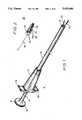
- FIG. 1is a perspective schematic of a clamp applicator constructed in accordance with the principles of the present invention.
- FIG. 2is a perspective view of a tethered clamp constructed in accordance with the principles of the present invention.
- FIGS. 3A-3Bare a front and top cross-sectional views, respectively, of the clamp applicator of FIG. 1.
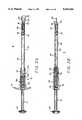
- FIGS. 4A and 4Bare front and top elevational views of the tethered clamp applicator of the present invention.
- FIGS. 5A-5Dare front and end elevational views of various embodiments of the tethered clamp of FIG. 2.
- FIGS. 6A-6Dare front elevational views illustrating the operation of the clamp applicator and tethered clamp of FIGS. 1 and 2.
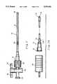
- FIG. 7is a front elevational view of an introducer and stopcock assembly constructed in accordance with the principles of the present invention.
- FIG. 7Ais a front elevational view of an alternative embodiment of the introducer of FIG. 7.
- FIG. 8Ais a front cross-sectional view of the stopcock of the FIG. 7.
- FIGS. 8B and 8Care top cross-sectional views of the stopcock of FIG. 7.
- FIG. 9is a front elevational view of an obturator for introducing the introducer/stopcock assembly of FIG. 7.
- FIG. 10is a front elevational view of a tether snare constructed in accordance with the principles of the present invention.
- FIGS. 10A-10Bare front elevational views of alternative embodiments of the tether snare of FIG. 9.
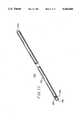
- FIG. 11is a perspective view of the positioning shaft of the invention.
- FIGS. 12-15are perspective views of the clamp applicator of FIG. 1 positioned through a trocar sleeve in the abdominal wall in accordance with the principles of the present invention.
- FIGS. 16-19are perspective views of the clamp applicator of FIG. 1 positioned through a trocar sleeve in the abdominal wall with the introducer and stopcock of FIG. 7 positioned through the abdominal wall in accordance with the principles of the present invention.
- FIG. 20is a perspective view of the clamp applicator of FIG. 1 positioned through a trocar sleeve with the tether snare of FIG. 10A introduced directly through the abdominal wall in accordance with the principles of the present invention.
- FIG. 21is a perspective view of the clamp applicator of FIG. 1 positioned through a trocar sleeve with the tethered clamp retracting tissue by attaching the free end to an external structure.
- FIG. 22is a perspective view of the clamp applicator of FIG. 1 positioned through a trocar sleeve with the tethered clamp retracting tissue by attaching the free end to an internal tissue structure.
- FIG. 23is a perspective view of a body cavity illustrating the use of the positioning shaft of FIG. 11.
- a tissue manipulation systemin a preferred aspect of the present invention, includes a clamp, a flexible tether attached to the clamp, and a clamp applicator for positioning the clamp through a trocar sleeve or other cannula and applying the clamp to a tissue location.
- the systemmay further include a rigid positioning shaft configured to engage the clamp and/or the tether to facilitate manipulation of tissue.
- the tissue manipulation systemcomprises an introducer and a retainer attached to the proximal end of the introducer for retaining the tether.
- the systemmay further include an obturator or an RF electrode for percutaneously inserting the introducer.
- the inventionalso provides a tether snare for retrieving the tether, which may be inserted through the introducer to draw the tether through the introducer to the retainer.
- the tether snaremay be provided with means for penetrating tissue to directly introduce the tether snare without need for the introducer or other cannula.
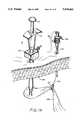
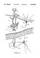
- the clamp applicatorcomprises a tubular handle 10, typically composed of polycarbonate or polysulfone, with a plunger 12 slidably mounted in handle 10.
- Tubular extension 14usually of polycarbonate or stainless steel, extends from the handle 10 distally and has an aperture 16 at its distal end.
- Plunger 12is coupled to a pair of movable arms 20 having a proximal portion disposed within extension 14 and a distal portion extending from the distal end of extension 14. Arms 20 have a pair of tips 22 for engaging the tethered clamp, which preferably have serrations on the inner surfaces thereof.
- tethered clamp 24has a pair of movable jaws 26 connected at hinge 28 and biased in a closed configuration by spring 30.
- a lever 36is attached to each of jaws 26 for opening and closing thereof.
- Levers 36will have a flat lateral surface for engagement by arms 20 of applicator 8.
- Flexible tether 32is attached to a proximal portion 34 of levers 36 through a hole 39, which is usually filled with adhesive.
- Handle 10includes a pair of grips 41 configured to be grasped by the user's fingers when plunger 12 is depressed with the thumb.
- plunger 12will have a knob, ring or other means 40 to facilitate application of pressure in the distal direction.
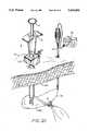
- Plunger 12is connected to a shaft 42 extending through handle 10.
- a proximal portion 43 of shaft 42is preferably circular in cross-section, while a distal portion 45 has a semicircular cross-section and extends distally through extension 14.
- the distal end of shaft 42is connected to a tubular sleeve 44 slidably disposed within extension 14 near its distal end.
- Sleeve 44has a rectangular aperture 46 at its distal end through which arms 20 extend, whereby distal movement of sleeve 44 causes arms 20 to close toward one another.
- Shank 47 of arms 20is fixed via pins 48 to arm support member 50 (FIG. 3B), which is fixed at its proximal end to handle 10 by a pin 52.
- Pin 52extends through a longitudinal slot 54 in shaft 42 to allow axial movement thereof.
- a spring 56is disposed about shaft 42 and is engaged by a retainer 58 fixed to shaft 42 to bias plunger 12 in a proximal position, such that arms 20 are in an open configuration when pressure is released.
- Clamp 24has a pair of movable jaws 26 having a contact plane 60 for engaging tissue when jaws 26 are closed.
- contact plane 60has a plurality of teeth 62 for improved grip on tissue, as shown in FIG. 5A.
- FIG. 5Billustrates a "Babcock” configuration, with jaws 26 meeting along a narrow, straight surface 61 at the distal end of the jaws.
- FIG. 5Cillustrates the "Kocher” type, with jaws 26 meeting at an overlapping point 63 and notch 65 at the distal end of the jaws.
- FIG. 5Aillustrates a "Babcock” configuration, with jaws 26 meeting along a narrow, straight surface 61 at the distal end of the jaws.
- FIG. 5Cillustrates the "Kocher” type, with jaws 26 meeting at an overlapping point 63 and notch 65 at the distal end of the jaws.
- jaws 26meet in a point 67 and notch 69 at the distal end as in the "Kocher” type, and further contact each other along teeth 71 proximal to the distal end.
- Other well-known clamp designsinclude, for example, Kelly, Allis, Glassman, Bulldog, DeBakey, and Cooley-type clamps, any of which may be used in conjunction with the present invention.
- Jaws 26are joined at hinge 28, which may comprise a pin or rivet.
- Spring 30is disposed around hinge 28, with a pair of extensions 64 engaging levers 36.
- Spring 30is configured to bias jaws 26 in a closed configuration by exerting outward force against levers 36.
- Tether 32extends through holes 39 in levers 36 and is tied to itself by a knot 43 forming a knotted loop 37.
- holes 39are filled with an adhesive.
- Tether 32preferably comprises medical grade monofilament polyester, polyamide or polypropylene line load rated to 10 lbs.
- tether 32may be elastic, so as to be resiliently extendable.
- Levers 36are engaged by tips 22 so as to permit clamp 24 to be rotationally positioned relative to clamp applicator 8 about an axis through tips 22.
- levers 36have a serrated surface for improved grip on the clamp by arms 20 of clamp applicator 8.
- a second clamp, hook, or other tissue engaging meansmay be detachably coupled to the free end of the tether or to a point along the tether between the clamp and the free end.
- the tetheris tensioned to position the clamp 24, and the tissue engaging means coupled to the tether is attached to a second portion of tissue to maintain clamp 24 in position (see FIG. 22, described below).
- FIGS. 6A-6DThe operation of clamp applicator 8 is illustrated in FIGS. 6A-6D. Tethered clamp 24 is positioned between arms 20 and plunger 12 is depressed to firmly engage the arms against levers 36 of the clamp. By further depressing plunger 12, tubular sleeve 44 is extended so as to press levers 36 together, thereby opening jaws 26. Allowing plunger 12 to retract causes levers 36 to move apart, closing jaws 26. As shown in FIG. 6C, when plunger 12 is in its fully retracted position, the gap between arms 20 is wider than the distance between levers 36, allowing the clamp applicator to be disengaged from clamp 24.
- the tethered clamp of the inventionmay also be introduced into a body cavity and applied to a tissue structure by means of a conventional needle holder in lieu of clamp applicator 8.
- Needle holders and other types of grasping forcepsare well-known for grasping a suture needle or tissue structure for purpose of suturing, ligating or manipulating a tissue structure.
- a needle holdermay be used for grasping levers 36 of the tethered clamp and introducing the clamp by inserting the needle holder through a trocar sleeve.
- a reducer sleeve of well-known constructionwill further be provided to facilitate introduction of a needle holder of reduced diameter, e.g.
- Needle holders as well as reducer sleeves suitable for use in the system of the present inventionare described in U.S. Pat. No. 5,211,650, application Ser. No. 07/912,353, the complete disclosure of which is incorporated herein by reference.
- Introducer 70comprises a tubular shaft 72, usually of medical grade polyurethane, PVC or polyethylene, having a taper 74 at its distal end and a female luer lock 76 or other mounting means at its proximal end.
- Stopcock 78has a male luer lock 80 which attaches to female luer lock 76 of introducer 70, forming a gas-tight seal to prevent gas from the insufflated abdominal cavity from escaping.
- An axial passageway 82extends from the distal end of introducer 70 to its proximal end at luer lock 76.
- Stopcock 78includes a valve assembly 84 having a valve handle 86 for opening and closing valve 84.
- stopcock 78includes a body 88 with a male luer lock 80 at its distal end and female luer lock 90 at its proximal end, with an axial passageway 92 extending therebetween.
- Valve 84extends transversely through a middle portion of body 88, and includes a rotatable shaft 94 attached to valve handle 86.
- Shaft 94has an orifice 96 which, when valve 84 is in an open position, is aligned with axial passageway 92.
- valve 84is closed by rotating handle 86 90°, providing an air tight seal between distal end 98 and shaft 94.
- the introducer/stopcock assemblyalso serves to retain tether 32 in tension so as to maintain tethered clamp 24 in a desired position.
- tether 32can be drawn through introducer 70 and through axial passageway 92 and orifice 96 of stopcock 78.
- valve 84When valve 84 is in an open position, as shown in FIG. 8B, tether 32 extends relatively straight through orifice 96 and axial passageway 92.
- handle 86is rotated 90°, as in FIG. 8C, orifice 96 is rotated so as to extend transversely to axial passageway 92, jamming portions of tether 32 against walls 100 of axial passageway 92 so as to clamp tether 32 firmly in position.
- an obturator 102is provided for percutaneously inserting introducer 70 into the abdomen or other body cavity.
- obturator 102includes a needle 104, usually comprising a 14 gauge needle of surgical steel. Needle 104 has a sharp point 106 for piercing the skin or other tissue. At the proximal end of needle 104 is a hub 110 which will usually be elongated for grasping by the user.
- An interconnect 108typically comprising a male luer lock, may also be provided for connection to stopcock 78. Needle 104 may be inserted through stopcock 78 and introducer 70, with point 106 extending from the distal end 74 of the introducer. Male luer lock 108 engages female luer lock 90 at the proximal end of stopcock body 88 to prevent gas leakage through stopcock 78 when obturator 104 is positioned through the introducer.
- introducer 70may be provided with an electrode at its distal end 74 through which energy may be applied to tissue for penetration thereof.
- the electrode 174will be coupled to an electrical connector 176 at the proximal end of introducer 70 which may be connected to an energy source, such as a thermal, ultrasonic or RF generator.
- electrode 174will comprise the distal end 74 of shaft 72, which is composed of a conductive metal such as stainless steel.
- Shaft 72is preferably covered by an insulative sleeve 178, which leaves only distal tip 74 exposed.
- Connector 176is electrically coupled to proximal end 76 of shaft 72, such that energy (e.g. RF current) is conducted from connector 176 through shaft 72 to distal tip electrode 174.
- the inventionfurther provides means for retrieving the tether 32 of tethered clamp 24.
- the means for retrieving the tethercomprises a tether snare 112 having an elongated rod 114, usually of stainless steel, with a hook 116 at its distal end.
- a male luer lock 118 and, desirably, a handle to facilitate manipulation,are attached to the proximal end of rod 114.
- rod 114 of tether snare 112may be inserted through stopcock 78 and introducer 70 such that hook 116 extends from the distal end of introducer 70.
- male luer lock 118engages with female luer lock 90 at the proximal end of stopcock 78. Tether snare 112 may then be positioned to retrieve tether 32 in hook 116 by tilting and/or rotating the introducer/stopcock assembly or longitudinally repositioning tether snare 112 within introducer 70. When tether 32 has been engaged by hook 116, male luer lock 118 may be released from luer lock 90 and tether snare 112 withdrawn from the introducer/stopcock assembly, drawing tether 32 through axial passageway 82 of introducer 70, and axial passageway 92 of stopcock 78.
- the tether snareis provided with an electrical connector 117 for connection to an electro-surgical generator 121.
- Generator 121may supply thermal, ultrasonic or radiofrequency energy to the tether snare through connector 117.
- Connector 117is coupled to rod 114. When current is supplied from the generator through the connector 117, hooked end 116 may be used to apply energy to the tissue at the desired site for introducing the tether snare.
- connector 117is connected to a radiofrequency (RF) electrosurgical generator 121, and the tether snare is percutaneously inserted by applying RF energy to the tissue.
- RFradiofrequency
- Hooked end 116will preferably have a tapered distal tip to facilitate penetration through tissue using ultrasonic, thermal or RF ablation.
- an insulative sleeve 119will be provided about rod 114 proximally of hooked end 116 so that current is conducted only through the hooked end. Tether snare 112 is thereby introduced without the need to position introducer 70 or other cannula as an access port to the body cavity.
- hooked end 116is formed in a sharp point, facilitating penetration of tissue by application of a distally-directed force to tether snare 112.
- the pointed hooked end 116 of tether snare 112allows the snare to be introduced without the need for introducer 70 or other cannula.
- the sharpened point of hooked end 116will be retractable, as in a Veress-type needle.
- Positioning shaft 150comprises a rigid rod 152 having a proximal end 154 and a distal end 156.
- Rod 152will typically be of surgical steel, and will have a diameter of minimal size, but one large enough to have sufficient column strength to allow a distal force to be applied to the rod without significant bending or deformation.
- the rodis 13 gauge.
- the distal end 156is configured to engage clamp 24 and/or tether 32, and will usually include a wire loop 158 having an eye 160 large enough for tether 32 to pass through. This permits the free end of the tether to be threaded through eye 160 so that the shaft may be guided toward the clamp along the tether.
- Loop 158may be formed by bending the distal end of rod 152 to form eye 160, or may be a separate piece of wire, usually of surgical steel, fixed to distal end 156 by adhesive, welding or the like.
- the shaftmay be guided along tether 32 toward the clamp until knot 43 engages eye 160, at which point further distal movement of shaft 150 will push clamp 24 away from the user to re-position the tissue to which the clamp is attached.
- a trocar sleeve 122 of well-known constructionis inserted through the abdominal wall 124 using known techniques.
- the abdominal cavitywill be distended using insufflation or other technique, and a laparoscope will be positioned within the body cavity to facilitate visualization of the surgical site.
- Trocar sleeve 122provides a sealed entryway into the abdominal cavity through which surgical instruments may be inserted.
- a clamp 24is placed in arms 20 of the clamp applicator with tips 22 of arms 20 engaging lever arms 36 of clamp 24.
- Extension 14 of the clamp applicatoris inserted through the trocar sleeve 122, with the free end 130 of tether 32 outside of the abdominal cavity.
- plunger 12 of the clamp applicatoris depressed toward handle 10, thereby extending sleeve 44 to close arms 20 and open jaws 26 of clamp 24.
- the open jaws 26are then positioned over a tissue location 126 by longitudinal, rotational and/or angular movement of clamp applicator 8.
- plunger 12is released so as to close jaws 26 on the tissue structure and release clamp 24 from the clamp applicator.
- clamp applicator 8is then partially retracted from trocar sleeve 122 so as to tension tether 32 between trocar sleeve 122 and clamp 24. This facilitates retrieving tether 32 in subsequent steps.
- introducer/stopcock assembly 70,78is inserted through abdominal wall 124 using obturator 102 mounted in introducer 70.
- Obturator 102is secured in introducer 70 by coupling male luer lock 108 to female luer lock 90 of stopcock 78.
- Point 106facilitates piercing of abdominal wall 124 for insertion of introducer 70.
- an RF electrode mounted at the distal end of introducer 70may be used to facilitate introduction (see FIG. 7A).
- valve handle 86is reopened and tether snare 112 is inserted through the introducer/stopcock assembly, as shown in FIG. 17.
- hook 116can be positioned to grasp tether 32 extending from clamp 24.
- tether 32is drawn through introducer 70 and stopcock 78 by withdrawing tether snare 112 from the introducer/stopcock assembly. Tether 32 is drawn through the introducer/stopcock assembly until free end 130 has been pulled through the proximal end of stopcock 78. The portion of tether 32 now outside of the abdominal cavity can be tensioned so as to position tissue location 126 as desired.
- tether 32can be locked in place by rotating valve handle 86 of stopcock 78, which further provides a gas-tight seal to maintain insufflation.
- the subsequent steps of the surgical proceduremay then be performed with tissue location 126 maintained in a stationary position.
- tether snare 112may be percutaneously introduced without the use of introducer 70 by direct penetration of tissue using the distal end of the snare.
- tether snare 112may have an electrode at its distal end for applying thermal, ultrasonic or RF energy to the tissue (FIGS. 9A and 20), or a sharpened distal point (FIG. 9B) for tissue penetration by exertion of a distally-directed force to the tether snare.
- the tether snaremay be used to retrieve the tether and withdraw it from the body cavity, as shown in FIG. 21.
- a second clamp 180may then be attached to the free end, and clamp 180 secured to an external structure such as surgical drapes 182.
- the free end of the tether 32may also be secured directly to the patient's skin using a separate clamp, such as a hemostosis clamp, or other temporary fastener, such as tape.
- tether 32may be left within the body cavity and coupled to a second clamp 170 or other tissue engaging means.
- Clamp 170may be fastened to a second tissue location 172 to maintain the tethered clamp in a desired position.
- positioning shaft 150is utilized, as illustrated in FIG. 23.
- the free end of tether 32has been withdrawn through introducer 70, the free end is threaded through eye 160 at the distal end of shaft 150.
- the positioning shaftis then introduced into the body cavity through the axial passage of the introducer.
- the periphery of rod 152seals within the axial passage to prevent leakage of insufflation gas.
- Slight tensionis maintained on the free end of the tether such that the shaft is guided along tether 32 through the introducer and toward clamp 24.
- the shaftis translated distally until eye 160 reaches knot 43. Knot 43 engages eye 160, such that further distal movement of shaft 150 will exert a force on clamp 24, pulling it away from the introducer to the desired position of retraction.
- This facility for retraction away from the introducermakes the present invention particularly useful for retraction of the gallbladder during, for example, laparoscopic cholecystectomies.
- positioning of the introducer high in the rib cage near the diaphragmpresents an undesirably high risk of injury to the patient.
- the present inventioneliminates the risk associated with introduction near the diaphragm by allowing the introducer to be positioned below the ribs and, through the use of positioning shaft 160, the gallbladder may be retracted away from the introducer toward the upper portion of the abdominal cavity.
- valve handle 86When tissue positioning is no longer required, shaft 150 is removed from the introducer, and tension on tether 32 is relieved by rotating valve handle 86 (or releasing the tissue engaging means at the free end of the tether). Clamp applicator 8 is then positioned with arms 20 over lever arms 36 of clamp 24, and plunger 12 is depressed to close arms 20 on lever arms 36, thereby opening jaws 26 of the clamp. Clamp applicator 8 is then withdrawn from trocar sleeve 122, pulling with it clamp 24 and tether 32. Valve handle 86 may then be rotated to close stopcock 78, preventing gas leakage through introducer 70.
Landscapes
- Health & Medical Sciences (AREA)
- Life Sciences & Earth Sciences (AREA)
- Surgery (AREA)
- Molecular Biology (AREA)
- Engineering & Computer Science (AREA)
- Biomedical Technology (AREA)
- Heart & Thoracic Surgery (AREA)
- Medical Informatics (AREA)
- Nuclear Medicine, Radiotherapy & Molecular Imaging (AREA)
- Animal Behavior & Ethology (AREA)
- General Health & Medical Sciences (AREA)
- Public Health (AREA)
- Veterinary Medicine (AREA)
- Reproductive Health (AREA)
- Vascular Medicine (AREA)
- Surgical Instruments (AREA)
Abstract
Description
Claims (79)
Priority Applications (3)
| Application Number | Priority Date | Filing Date | Title |
|---|---|---|---|
| US08/027,505US5415666A (en) | 1992-03-23 | 1993-03-04 | Tethered clamp retractor |
| PCT/US1993/002670WO1993018712A1 (en) | 1992-03-23 | 1993-03-19 | Tethered clamp retractor |
| AU39302/93AAU3930293A (en) | 1992-03-23 | 1993-03-19 | Tethered clamp retractor |
Applications Claiming Priority (2)
| Application Number | Priority Date | Filing Date | Title |
|---|---|---|---|
| US07/855,766US5304183A (en) | 1992-03-23 | 1992-03-23 | Tethered clamp retractor |
| US08/027,505US5415666A (en) | 1992-03-23 | 1993-03-04 | Tethered clamp retractor |
Related Parent Applications (1)
| Application Number | Title | Priority Date | Filing Date |
|---|---|---|---|
| US07/855,766Continuation-In-PartUS5304183A (en) | 1992-03-23 | 1992-03-23 | Tethered clamp retractor |
Publications (1)
| Publication Number | Publication Date |
|---|---|
| US5415666Atrue US5415666A (en) | 1995-05-16 |
Family
ID=26702554
Family Applications (1)
| Application Number | Title | Priority Date | Filing Date |
|---|---|---|---|
| US08/027,505Expired - LifetimeUS5415666A (en) | 1992-03-23 | 1993-03-04 | Tethered clamp retractor |
Country Status (3)
| Country | Link |
|---|---|
| US (1) | US5415666A (en) |
| AU (1) | AU3930293A (en) |
| WO (1) | WO1993018712A1 (en) |
Cited By (82)
| Publication number | Priority date | Publication date | Assignee | Title |
|---|---|---|---|---|
| WO1996032148A1 (en)* | 1995-04-12 | 1996-10-17 | Symbiosis Corporation | Veress needle and cannula assembly |
| US5658298A (en)* | 1993-11-09 | 1997-08-19 | Inamed Development Company | Laparoscopic tool |
| US5795325A (en)* | 1991-07-16 | 1998-08-18 | Heartport, Inc. | Methods and apparatus for anchoring an occluding member |
| WO1998051223A1 (en) | 1997-05-16 | 1998-11-19 | Guidant Corporation | Apparatus and method for cardiac stabilization and arterial occlusion |
| US5911702A (en)* | 1997-11-06 | 1999-06-15 | Heartport, Inc. | Methods and devices for cannulating a patient's blood vessel |
| US5921979A (en)* | 1996-12-18 | 1999-07-13 | Guidant Corporation | Apparatus and method for tissue and organ stabilization |
| US5921996A (en)* | 1997-05-02 | 1999-07-13 | Cardio Thoracic Systems, Inc. | Surgical clamp applier/remover and detachable clamp |
| US5976069A (en)* | 1996-07-25 | 1999-11-02 | Guidant Corporation | Epicardial immobilization device |
| US6182664B1 (en) | 1996-02-19 | 2001-02-06 | Edwards Lifesciences Corporation | Minimally invasive cardiac valve surgery procedure |
| US20030114874A1 (en)* | 2001-11-08 | 2003-06-19 | Craig H. Wayne | Ultrasonic clamp coagulator apparatus having an improved clamping end-effector |
| US20030195593A1 (en)* | 1996-11-08 | 2003-10-16 | Surx, Inc. | Devices, methods, and systems for shrinking tissues |
| US20040050392A1 (en)* | 2001-08-28 | 2004-03-18 | Hosheng Tu | Glaucoma stent for treating glaucoma and methods of use |
| US20050159650A1 (en)* | 2003-12-18 | 2005-07-21 | Depuy Spine, Inc. | Surgical methods and surgical kits |
| US20050177177A1 (en)* | 2002-04-10 | 2005-08-11 | Viola Frank J. | Surgical clip applier with high torque jaws |
| US20060025787A1 (en)* | 2002-06-13 | 2006-02-02 | Guided Delivery Systems, Inc. | Devices and methods for heart valve repair |
| US20060167533A1 (en)* | 2005-01-21 | 2006-07-27 | Solarant Medical, Inc. | Endo-pelvic fascia penetrating heating systems and methods for incontinence treatment |
| US20060195125A1 (en)* | 2003-03-06 | 2006-08-31 | Ghassan Sakakine | Spring clip and method for assembling same |
| US7137988B2 (en)* | 2001-03-03 | 2006-11-21 | Frye Darrin L | Needle driver |
| US20070073341A1 (en)* | 2005-07-26 | 2007-03-29 | Kms Medical Llc | Method for operating a surgical stapling and cutting device |
| US20070112361A1 (en)* | 2005-11-07 | 2007-05-17 | Schonholz Steven M | Surgical repair systems and methods of using the same |
| US20070156024A1 (en)* | 2006-01-04 | 2007-07-05 | William Frasier | Surgical Retractors and Methods of Minimally Invasive Surgery |
| US20070156023A1 (en)* | 2006-01-05 | 2007-07-05 | Depuy Spine, Inc. | Non-rigid surgical retractor |
| US20070156026A1 (en)* | 2006-01-04 | 2007-07-05 | William Frasier | Surgical access devices and methods of minimally invasive surgery |
| US20080021285A1 (en)* | 2006-01-04 | 2008-01-24 | Anne Drzyzga | Surgical retractor for use with minimally invasive spinal stabilization systems and methods of minimally invasive surgery |
| US20080132915A1 (en)* | 2002-09-13 | 2008-06-05 | Buckman Robert F | Method and apparatus for vascular and visceral clipping |
| WO2008071821A1 (en)* | 2006-12-14 | 2008-06-19 | Universidad De Zaragoza | Clamp for tubular members intended for use in endoscopic surgery |
| US20080195135A1 (en)* | 2007-02-12 | 2008-08-14 | Alcon, Inc. | Surgical Probe |
| US20090062618A1 (en)* | 2007-08-29 | 2009-03-05 | Ethicon Endo-Surgery, Inc. | Tissue retractors |
| US20090137877A1 (en)* | 2007-11-26 | 2009-05-28 | Ethicon Endo-Surgery, Inc. | Tissue retractors |
| US20090198107A1 (en)* | 2006-10-10 | 2009-08-06 | Park Adrian E | Adjustable Line and Net Retractors |
| US20100191260A1 (en)* | 2009-01-23 | 2010-07-29 | Mohajer Reza S | Veress needle with illuminated guidance and suturing capability |
| US20100249498A1 (en)* | 2009-03-24 | 2010-09-30 | Tyco Healthcare Group Lp | Endoscopic Apparatus for Manipulating Tissue |
| US20100268254A1 (en)* | 2007-11-12 | 2010-10-21 | Joe Alan Golden | Clamp System and Method of Using the Same |
| US20110040322A1 (en)* | 2009-07-27 | 2011-02-17 | Tracey Stribling | Device & method for the positioning of tissue during laparoscopic or endoscopic surgery |
| US20110040153A1 (en)* | 2009-08-13 | 2011-02-17 | Tyco Healthcare Group Lp | Deployable jaws retraction device |
| US20110046437A1 (en)* | 2009-08-24 | 2011-02-24 | Cvdevices, Llc | Tissue restoration devices, systems, and methods |
| US20110046641A1 (en)* | 2009-08-24 | 2011-02-24 | Cvdevices, Llc | Devices, systems and methods for tissue restoration |
| WO2011050387A1 (en)* | 2009-10-29 | 2011-05-05 | Jason Jit-Sun Tan | A minimally invasive surgical technique to retract target issue in a body cavity |
| US20120116153A1 (en)* | 2009-02-25 | 2012-05-10 | Mis Solutions, Inc. | Apparatus and method for intra-abdominally moving a first internal organ to a position away from a second internal organ and then holding the first internal organ in the position without manual input |
| EP2182853A4 (en)* | 2007-08-10 | 2012-08-08 | Univ Yale | SUSPENSION / RETRACTION DEVICE FOR SURGICAL HANDLING |
| US20130190572A1 (en)* | 2011-02-18 | 2013-07-25 | Jeong Sam Lee | Retraction system for laparoscopic surgery |
| US8506515B2 (en) | 2006-11-10 | 2013-08-13 | Glaukos Corporation | Uveoscleral shunt and methods for implanting same |
| US20130324803A1 (en)* | 2009-01-23 | 2013-12-05 | Reza S. Mohajer | Veress needle with illuminated guidance and suturing capability |
| US20140121464A1 (en)* | 1999-01-26 | 2014-05-01 | Meditech Development Incorporated | Vacuum instrument for slowing or arresting the flow of blood |
| US20150025322A1 (en)* | 2011-06-28 | 2015-01-22 | Novatract Surgical, Inc. | Tissue Retractor Assembly |
| US8986330B2 (en) | 2013-07-12 | 2015-03-24 | Miami Instruments Llc | Aortic cross clamp |
| WO2015044865A1 (en)* | 2013-09-24 | 2015-04-02 | Chinmay Deodhar | A system to manipulate organs and instruments for minimally invasive surgery |
| US20160038131A1 (en)* | 2014-08-07 | 2016-02-11 | Biomet Manufacturing, Llc | Instrument deployed tissue protector |
| US9439651B2 (en) | 2006-05-19 | 2016-09-13 | Ethicon Endo-Surgery, Llc | Methods for cryptographic identification of interchangeable parts for surgical instruments |
| US9451941B2 (en) | 2011-08-25 | 2016-09-27 | Freehold Surgical, Inc. | System for intra-abdominally moving an organ |
| US20160339189A1 (en)* | 2013-02-25 | 2016-11-24 | Covidien Lp | Flexible Access Assembly |
| US9554940B2 (en) | 2012-03-26 | 2017-01-31 | Glaukos Corporation | System and method for delivering multiple ocular implants |
| US9554803B2 (en) | 2005-07-26 | 2017-01-31 | Ethicon Endo-Surgery, Llc | Electrically self-powered surgical instrument with manual release |
| US9572963B2 (en) | 2001-04-07 | 2017-02-21 | Glaukos Corporation | Ocular disorder treatment methods and systems |
| US9592151B2 (en) | 2013-03-15 | 2017-03-14 | Glaukos Corporation | Systems and methods for delivering an ocular implant to the suprachoroidal space within an eye |
| US9597230B2 (en) | 2002-04-08 | 2017-03-21 | Glaukos Corporation | Devices and methods for glaucoma treatment |
| US9616197B2 (en) | 2009-01-20 | 2017-04-11 | Ancora Heart, Inc. | Anchor deployment devices and related methods |
| US9622744B2 (en) | 2006-05-19 | 2017-04-18 | Ethicon Endo-Surgery, Llc | Electrical surgical instrument with one-handed operation |
| US9662116B2 (en) | 2006-05-19 | 2017-05-30 | Ethicon, Llc | Electrically self-powered surgical instrument with cryptographic identification of interchangeable part |
| US20170296197A1 (en)* | 2014-10-24 | 2017-10-19 | Kaneka Corporation | Clip device for endoscope and method for installing indwelling clip |
| US9855044B2 (en) | 2012-06-29 | 2018-01-02 | Freehold Surgical, Inc. | Apparatus and method for delivering surgical tissue connectors into an abdominal cavity and removing the surgical tissue connectors from the abdominal cavity |
| US9980841B2 (en) | 2009-08-24 | 2018-05-29 | Cvdevices, Llc | Devices and systems configured to fit around a tissue using the same |
| US9993368B2 (en) | 2000-04-14 | 2018-06-12 | Glaukos Corporation | System and method for treating an ocular disorder |
| US10058321B2 (en) | 2015-03-05 | 2018-08-28 | Ancora Heart, Inc. | Devices and methods of visualizing and determining depth of penetration in cardiac tissue |
| USD846738S1 (en) | 2017-10-27 | 2019-04-23 | Glaukos Corporation | Implant delivery apparatus |
| US10314583B2 (en) | 2005-07-26 | 2019-06-11 | Ethicon Llc | Electrically self-powered surgical instrument with manual release |
| CN110664445A (en)* | 2019-11-05 | 2020-01-10 | 江苏唯德康医疗科技有限公司 | Tissue drag hook and medical retractor with same |
| RU198890U1 (en)* | 2019-06-26 | 2020-07-30 | федеральное государственное автономное образовательное учреждение высшего образования "Российский университет дружбы народов" (РУДН) | Surgical probe |
| US11033278B2 (en) | 2017-11-08 | 2021-06-15 | Mayo Foundation For Medical Education And Research | Systems and methods for endoscopic submucosal dissection using magnetically attachable clips |
| US11109850B2 (en) | 2017-03-20 | 2021-09-07 | Boston Scientific Scimed, Inc. | Tissue retraction device and delivery system |
| US11116625B2 (en) | 2017-09-28 | 2021-09-14 | Glaukos Corporation | Apparatus and method for controlling placement of intraocular implants |
| US11266393B2 (en) | 2018-03-14 | 2022-03-08 | Boston Scientific Scimed, Inc. | Tissue retraction device and delivery system |
| US11350946B2 (en)* | 2017-11-08 | 2022-06-07 | Mayo Foundation For Medical Education And Research | Systems and methods for endoscopic submucosal dissection using magnetically attachable clips |
| US11376040B2 (en) | 2017-10-06 | 2022-07-05 | Glaukos Corporation | Systems and methods for delivering multiple ocular implants |
| US11672524B2 (en) | 2019-07-15 | 2023-06-13 | Ancora Heart, Inc. | Devices and methods for tether cutting |
| US11690679B2 (en) | 2019-01-08 | 2023-07-04 | Covidien Lp | Localization systems and methods of use |
| US11737679B2 (en) | 2019-01-08 | 2023-08-29 | Covidien Lp | Localization systems and methods of use |
| US20230277272A1 (en)* | 2022-03-02 | 2023-09-07 | Ning FAN | In vivo large organ turnover and fixing device applied in minimally invasive surgery |
| US11751873B2 (en) | 2005-07-26 | 2023-09-12 | Cilag Gmbh International | Electrically powered surgical instrument with manual release |
| US12009166B2 (en) | 2006-05-19 | 2024-06-11 | Cilag Gmbh International | Force switch |
| US12419783B2 (en) | 2010-11-24 | 2025-09-23 | Glaukos Corporation | Drug eluting ocular implant |
| US12419623B2 (en) | 2016-01-21 | 2025-09-23 | The Cleveland Clinic Foundation | System, method, and apparatus for assisting with submucosal dissections |
Families Citing this family (14)
| Publication number | Priority date | Publication date | Assignee | Title |
|---|---|---|---|---|
| US5735290A (en) | 1993-02-22 | 1998-04-07 | Heartport, Inc. | Methods and systems for performing thoracoscopic coronary bypass and other procedures |
| US5569274A (en)* | 1993-02-22 | 1996-10-29 | Heartport, Inc. | Endoscopic vascular clamping system and method |
| US6494211B1 (en) | 1993-02-22 | 2002-12-17 | Hearport, Inc. | Device and methods for port-access multivessel coronary artery bypass surgery |
| US5545169A (en)* | 1993-04-01 | 1996-08-13 | Yarger; Richard J. | Laparoscopic delivery device |
| FR2713471B1 (en)* | 1993-12-10 | 1996-03-01 | Peters | Surgical instrument for the implementation of treatments for venous dilations, especially varicose veins. |
| US5618307A (en)* | 1995-04-03 | 1997-04-08 | Heartport, Inc. | Clamp assembly and method of use |
| US5792149A (en)* | 1996-10-03 | 1998-08-11 | United States Surgical Corporation | Clamp applicator |
| US5928251A (en)* | 1997-09-18 | 1999-07-27 | United States Surgical Corporation | Occlusion clamp and occlusion clamp applicator |
| US7128739B2 (en)* | 2001-11-02 | 2006-10-31 | Vivant Medical, Inc. | High-strength microwave antenna assemblies and methods of use |
| AT507660B1 (en)* | 2009-04-23 | 2010-07-15 | A M I Agency For Medical Innov | SURGICAL INSTRUMENT |
| US8459524B2 (en) | 2009-08-14 | 2013-06-11 | Covidien Lp | Tissue fastening system for a medical device |
| US8551078B2 (en) | 2009-12-04 | 2013-10-08 | Covidien Lp | Laparoscopic scaffold assembly |
| GB2476461A (en)* | 2009-12-22 | 2011-06-29 | Neosurgical Ltd | Laparoscopic surgical device with jaws biased closed |
| RU187484U1 (en)* | 2018-11-26 | 2019-03-06 | Федеральное государственное бюджетное образовательное учреждение высшего образования "Курский государственный медицинский университет" Министерства здравоохранения Российской Федерации | DEVICE FOR FIXING WORKING HEADS OF MEDICAL INSTRUMENTS |
Citations (33)
| Publication number | Priority date | Publication date | Assignee | Title |
|---|---|---|---|---|
| US1274669A (en)* | 1918-01-14 | 1918-08-06 | Frank Bohn | Surgical instrument. |
| US2549731A (en)* | 1944-12-18 | 1951-04-17 | Vincent E Wattley | Flexible test prod |
| US3404677A (en)* | 1965-07-08 | 1968-10-08 | Henry A. Springer | Biopsy and tissue removing device |
| US3809094A (en)* | 1969-12-24 | 1974-05-07 | G Cook | Tongue extender |
| US3877434A (en)* | 1974-02-11 | 1975-04-15 | Sherwood Medical Ind Inc | Vascular tourniquet |
| GB1452185A (en)* | 1973-05-19 | 1976-10-13 | Wolf Gmbh Richard | Forceps instruments |
| US3994287A (en)* | 1974-07-01 | 1976-11-30 | Centre De Recherche Industrielle Du Quebec | Trocar |
| US4046149A (en)* | 1975-01-31 | 1977-09-06 | Olympus Optical Co., Ltd. | Instrument for removing a foreign substance from the body cavity of human being |
| US4051844A (en)* | 1976-05-07 | 1977-10-04 | Medico Developments, Inc. | Telescoping neurosurgical scalp retractor |
| US4174715A (en)* | 1977-03-28 | 1979-11-20 | Hasson Harrith M | Multi-pronged laparoscopy forceps |
| US4177813A (en)* | 1978-01-09 | 1979-12-11 | Med General, Inc. | Vessel occluder |
| US4374523A (en)* | 1974-10-29 | 1983-02-22 | Yoon In B | Occlusion ring applicator |
| US4393872A (en)* | 1980-05-27 | 1983-07-19 | Eder Instrument Co., Inc. | Aspirating surgical forceps |
| US4519392A (en)* | 1982-10-12 | 1985-05-28 | Lingua Robert W | Hemostasing muscle clips for needleless surgery |
| US4605990A (en)* | 1984-01-21 | 1986-08-12 | Wilder Joseph R | Surgical clip-on light pipe illumination assembly |
| US4607620A (en)* | 1983-02-08 | 1986-08-26 | Karl Storz | Medical gripping instrument |
| US4617933A (en)* | 1980-02-19 | 1986-10-21 | Hasson Harrith M | Laparoscope cannula with improved suture receiving means |
| US4681107A (en)* | 1985-12-31 | 1987-07-21 | Kees Surgical Specialty Co. | Device for holding an aneurysm clip |
| US4706668A (en)* | 1985-09-16 | 1987-11-17 | B & B Tools | Aneurysm clip pliers |
| US4777949A (en)* | 1987-05-08 | 1988-10-18 | Metatech Corporation | Surgical clip for clamping small blood vessels in brain surgery and the like |
| US4779616A (en)* | 1986-02-04 | 1988-10-25 | Johnson Lanny L | Surgical suture-snagging method |
| US4796626A (en)* | 1987-04-15 | 1989-01-10 | Dlp Inc. | Tourniquet tube |
| US4932955A (en)* | 1984-06-29 | 1990-06-12 | Baxter International Inc. | Clip |
| US4988355A (en)* | 1990-01-16 | 1991-01-29 | Leveen Eric G | Arterial clamp |
| US4990157A (en)* | 1989-11-13 | 1991-02-05 | Robhill Industries Inc. | Soother retainer |
| US5022693A (en)* | 1989-12-14 | 1991-06-11 | Cornell Research Foundation, Inc. | Ostomy bag holder |
| US5059202A (en)* | 1988-10-27 | 1991-10-22 | The Montefiore Hospital Association Of Western Pennsylvania | Tendon approximator |
| US5074869A (en)* | 1988-09-26 | 1991-12-24 | Daicoff George R | Vascular occlusion device |
| US5074870A (en)* | 1989-10-06 | 1991-12-24 | Zeppelin Dieter Von | Clamp for clamping blood vessels or aneurysms |
| JPH04226643A (en)* | 1990-12-29 | 1992-08-17 | Masataka Funada | Implement for medical treatment |
| US5201714A (en)* | 1992-03-05 | 1993-04-13 | Conmed Corporation | Laparoscopic cannula |
| US5242456A (en)* | 1991-11-21 | 1993-09-07 | Kensey Nash Corporation | Apparatus and methods for clamping tissue and reflecting the same |
| US5261895A (en)* | 1991-09-26 | 1993-11-16 | Stryker Corporation | Apparatus for guiding surgical instruments into a surgical site and blocking escape of fluids from the site |
- 1993
- 1993-03-04USUS08/027,505patent/US5415666A/ennot_activeExpired - Lifetime
- 1993-03-19WOPCT/US1993/002670patent/WO1993018712A1/enactiveApplication Filing
- 1993-03-19AUAU39302/93Apatent/AU3930293A/ennot_activeAbandoned
Patent Citations (33)
| Publication number | Priority date | Publication date | Assignee | Title |
|---|---|---|---|---|
| US1274669A (en)* | 1918-01-14 | 1918-08-06 | Frank Bohn | Surgical instrument. |
| US2549731A (en)* | 1944-12-18 | 1951-04-17 | Vincent E Wattley | Flexible test prod |
| US3404677A (en)* | 1965-07-08 | 1968-10-08 | Henry A. Springer | Biopsy and tissue removing device |
| US3809094A (en)* | 1969-12-24 | 1974-05-07 | G Cook | Tongue extender |
| GB1452185A (en)* | 1973-05-19 | 1976-10-13 | Wolf Gmbh Richard | Forceps instruments |
| US3877434A (en)* | 1974-02-11 | 1975-04-15 | Sherwood Medical Ind Inc | Vascular tourniquet |
| US3994287A (en)* | 1974-07-01 | 1976-11-30 | Centre De Recherche Industrielle Du Quebec | Trocar |
| US4374523A (en)* | 1974-10-29 | 1983-02-22 | Yoon In B | Occlusion ring applicator |
| US4046149A (en)* | 1975-01-31 | 1977-09-06 | Olympus Optical Co., Ltd. | Instrument for removing a foreign substance from the body cavity of human being |
| US4051844A (en)* | 1976-05-07 | 1977-10-04 | Medico Developments, Inc. | Telescoping neurosurgical scalp retractor |
| US4174715A (en)* | 1977-03-28 | 1979-11-20 | Hasson Harrith M | Multi-pronged laparoscopy forceps |
| US4177813A (en)* | 1978-01-09 | 1979-12-11 | Med General, Inc. | Vessel occluder |
| US4617933A (en)* | 1980-02-19 | 1986-10-21 | Hasson Harrith M | Laparoscope cannula with improved suture receiving means |
| US4393872A (en)* | 1980-05-27 | 1983-07-19 | Eder Instrument Co., Inc. | Aspirating surgical forceps |
| US4519392A (en)* | 1982-10-12 | 1985-05-28 | Lingua Robert W | Hemostasing muscle clips for needleless surgery |
| US4607620A (en)* | 1983-02-08 | 1986-08-26 | Karl Storz | Medical gripping instrument |
| US4605990A (en)* | 1984-01-21 | 1986-08-12 | Wilder Joseph R | Surgical clip-on light pipe illumination assembly |
| US4932955A (en)* | 1984-06-29 | 1990-06-12 | Baxter International Inc. | Clip |
| US4706668A (en)* | 1985-09-16 | 1987-11-17 | B & B Tools | Aneurysm clip pliers |
| US4681107A (en)* | 1985-12-31 | 1987-07-21 | Kees Surgical Specialty Co. | Device for holding an aneurysm clip |
| US4779616A (en)* | 1986-02-04 | 1988-10-25 | Johnson Lanny L | Surgical suture-snagging method |
| US4796626A (en)* | 1987-04-15 | 1989-01-10 | Dlp Inc. | Tourniquet tube |
| US4777949A (en)* | 1987-05-08 | 1988-10-18 | Metatech Corporation | Surgical clip for clamping small blood vessels in brain surgery and the like |
| US5074869A (en)* | 1988-09-26 | 1991-12-24 | Daicoff George R | Vascular occlusion device |
| US5059202A (en)* | 1988-10-27 | 1991-10-22 | The Montefiore Hospital Association Of Western Pennsylvania | Tendon approximator |
| US5074870A (en)* | 1989-10-06 | 1991-12-24 | Zeppelin Dieter Von | Clamp for clamping blood vessels or aneurysms |
| US4990157A (en)* | 1989-11-13 | 1991-02-05 | Robhill Industries Inc. | Soother retainer |
| US5022693A (en)* | 1989-12-14 | 1991-06-11 | Cornell Research Foundation, Inc. | Ostomy bag holder |
| US4988355A (en)* | 1990-01-16 | 1991-01-29 | Leveen Eric G | Arterial clamp |
| JPH04226643A (en)* | 1990-12-29 | 1992-08-17 | Masataka Funada | Implement for medical treatment |
| US5261895A (en)* | 1991-09-26 | 1993-11-16 | Stryker Corporation | Apparatus for guiding surgical instruments into a surgical site and blocking escape of fluids from the site |
| US5242456A (en)* | 1991-11-21 | 1993-09-07 | Kensey Nash Corporation | Apparatus and methods for clamping tissue and reflecting the same |
| US5201714A (en)* | 1992-03-05 | 1993-04-13 | Conmed Corporation | Laparoscopic cannula |
Non-Patent Citations (2)
| Title |
|---|
| K. R. Loughlin, "Use of the Scott Ring Surgical Retractor for Illio-inguinal Node Dissection", British Journal of Urology, (1988), 60, 367-368. |
| K. R. Loughlin, Use of the Scott Ring Surgical Retractor for Illio inguinal Node Dissection , British Journal of Urology, (1988), 60, 367 368.* |
Cited By (183)
| Publication number | Priority date | Publication date | Assignee | Title |
|---|---|---|---|---|
| US6251093B1 (en) | 1991-07-16 | 2001-06-26 | Heartport, Inc. | Methods and apparatus for anchoring an occluding member |
| US5795325A (en)* | 1991-07-16 | 1998-08-18 | Heartport, Inc. | Methods and apparatus for anchoring an occluding member |
| US20050148997A1 (en)* | 1991-07-16 | 2005-07-07 | Valley Kirsten L. | Methods and apparatus for anchoring an occluding member |
| US5658298A (en)* | 1993-11-09 | 1997-08-19 | Inamed Development Company | Laparoscopic tool |
| US5669883A (en)* | 1995-04-12 | 1997-09-23 | Symbiosis Corporation | Veress needle and cannula assembly |
| WO1996032148A1 (en)* | 1995-04-12 | 1996-10-17 | Symbiosis Corporation | Veress needle and cannula assembly |
| US6539945B2 (en) | 1996-02-19 | 2003-04-01 | The Cleveland Clinic Foundation | Minimally invasive cardiac surgery procedure |
| US20050092333A1 (en)* | 1996-02-19 | 2005-05-05 | Cosgrove Delos M. | Minimally invasive cardiac surgery procedure |
| US6182664B1 (en) | 1996-02-19 | 2001-02-06 | Edwards Lifesciences Corporation | Minimally invasive cardiac valve surgery procedure |
| US6732739B2 (en) | 1996-02-19 | 2004-05-11 | The Cleveland Clinic Foundation | Minimally invasive cardiac surgery procedure |
| US5976069A (en)* | 1996-07-25 | 1999-11-02 | Guidant Corporation | Epicardial immobilization device |
| US20030195593A1 (en)* | 1996-11-08 | 2003-10-16 | Surx, Inc. | Devices, methods, and systems for shrinking tissues |
| US6206827B1 (en) | 1996-12-18 | 2001-03-27 | Guidant Corporation | Apparatus and method for tissue and organ stabilization |
| US5921979A (en)* | 1996-12-18 | 1999-07-13 | Guidant Corporation | Apparatus and method for tissue and organ stabilization |
| US5921996A (en)* | 1997-05-02 | 1999-07-13 | Cardio Thoracic Systems, Inc. | Surgical clamp applier/remover and detachable clamp |
| WO1998051223A1 (en) | 1997-05-16 | 1998-11-19 | Guidant Corporation | Apparatus and method for cardiac stabilization and arterial occlusion |
| US5911702A (en)* | 1997-11-06 | 1999-06-15 | Heartport, Inc. | Methods and devices for cannulating a patient's blood vessel |
| US20140121464A1 (en)* | 1999-01-26 | 2014-05-01 | Meditech Development Incorporated | Vacuum instrument for slowing or arresting the flow of blood |
| US9993368B2 (en) | 2000-04-14 | 2018-06-12 | Glaukos Corporation | System and method for treating an ocular disorder |
| US10485702B2 (en) | 2000-04-14 | 2019-11-26 | Glaukos Corporation | System and method for treating an ocular disorder |
| US7137988B2 (en)* | 2001-03-03 | 2006-11-21 | Frye Darrin L | Needle driver |
| US10828473B2 (en) | 2001-04-07 | 2020-11-10 | Glaukos Corporation | Ocular implant delivery system and methods thereof |
| US9572963B2 (en) | 2001-04-07 | 2017-02-21 | Glaukos Corporation | Ocular disorder treatment methods and systems |
| US9987472B2 (en) | 2001-04-07 | 2018-06-05 | Glaukos Corporation | Ocular implant delivery systems |
| US9561131B2 (en) | 2001-08-28 | 2017-02-07 | Glaukos Corporation | Implant delivery system and methods thereof for treating ocular disorders |
| US10285856B2 (en) | 2001-08-28 | 2019-05-14 | Glaukos Corporation | Implant delivery system and methods thereof for treating ocular disorders |
| US20060241749A1 (en)* | 2001-08-28 | 2006-10-26 | Hosheng Tu | Glaucoma stent system |
| US20070010827A1 (en)* | 2001-08-28 | 2007-01-11 | Hosheng Tu | Glaucoma stent system |
| US7331984B2 (en)* | 2001-08-28 | 2008-02-19 | Glaukos Corporation | Glaucoma stent for treating glaucoma and methods of use |
| US20040050392A1 (en)* | 2001-08-28 | 2004-03-18 | Hosheng Tu | Glaucoma stent for treating glaucoma and methods of use |
| US7879079B2 (en) | 2001-08-28 | 2011-02-01 | Glaukos Corporation | Implant delivery system and methods thereof for treating ocular disorders |
| US20060030848A1 (en)* | 2001-11-08 | 2006-02-09 | Craig H W | Ultrasonic clamp coagulator apparatus having an improved clamping end-effector |
| US20030114874A1 (en)* | 2001-11-08 | 2003-06-19 | Craig H. Wayne | Ultrasonic clamp coagulator apparatus having an improved clamping end-effector |
| US10485701B2 (en) | 2002-04-08 | 2019-11-26 | Glaukos Corporation | Devices and methods for glaucoma treatment |
| US9597230B2 (en) | 2002-04-08 | 2017-03-21 | Glaukos Corporation | Devices and methods for glaucoma treatment |
| US20050177177A1 (en)* | 2002-04-10 | 2005-08-11 | Viola Frank J. | Surgical clip applier with high torque jaws |
| US8512357B2 (en) | 2002-04-10 | 2013-08-20 | Covidien Lp | Surgical clip applier with high torque jaws |
| US20060025787A1 (en)* | 2002-06-13 | 2006-02-02 | Guided Delivery Systems, Inc. | Devices and methods for heart valve repair |
| US20080234701A1 (en)* | 2002-06-13 | 2008-09-25 | Guided Delivery Systems, Inc. | Devices and methods for heart valve repair |
| US20080234702A1 (en)* | 2002-06-13 | 2008-09-25 | Guided Delivery Systems, Inc. | Devices and methods for heart valve repair |
| US9636107B2 (en) | 2002-06-13 | 2017-05-02 | Ancora Heart, Inc. | Devices and methods for heart valve repair |
| US20080132915A1 (en)* | 2002-09-13 | 2008-06-05 | Buckman Robert F | Method and apparatus for vascular and visceral clipping |
| US8187290B2 (en)* | 2002-09-13 | 2012-05-29 | Damage Control Surgical Technologies, Inc. | Method and apparatus for vascular and visceral clipping |
| US20060195125A1 (en)* | 2003-03-06 | 2006-08-31 | Ghassan Sakakine | Spring clip and method for assembling same |
| US7780688B2 (en)* | 2003-03-06 | 2010-08-24 | Applied Medical Resources Corporation | Spring clip and method for assembling same |
| US8622897B2 (en) | 2003-12-18 | 2014-01-07 | DePuy Synthes Products, LLC | Surgical methods and surgical kits |
| US8038611B2 (en) | 2003-12-18 | 2011-10-18 | Depuy Spine, Inc. | Surgical methods and surgical kits |
| US20090018400A1 (en)* | 2003-12-18 | 2009-01-15 | Depuy Spine, Inc. | Surgical retractor systems and illuminated cannulae |
| US8602984B2 (en) | 2003-12-18 | 2013-12-10 | DePuy Synthes Products, LLC | Surgical retractor systems and illuminated cannulae |
| US20050159650A1 (en)* | 2003-12-18 | 2005-07-21 | Depuy Spine, Inc. | Surgical methods and surgical kits |
| US10869657B2 (en) | 2003-12-18 | 2020-12-22 | DePuy Synthes Products, Inc. | Surgical retractor systems and illuminated cannulae |
| US20060167533A1 (en)* | 2005-01-21 | 2006-07-27 | Solarant Medical, Inc. | Endo-pelvic fascia penetrating heating systems and methods for incontinence treatment |
| US7536225B2 (en) | 2005-01-21 | 2009-05-19 | Ams Research Corporation | Endo-pelvic fascia penetrating heating systems and methods for incontinence treatment |
| US11751873B2 (en) | 2005-07-26 | 2023-09-12 | Cilag Gmbh International | Electrically powered surgical instrument with manual release |
| US11172930B2 (en) | 2005-07-26 | 2021-11-16 | Cilag Gmbh International | Electrically self-powered surgical instrument with manual release |
| US11234695B2 (en) | 2005-07-26 | 2022-02-01 | Cilag Gmbh International | Surgical stapling and cutting device |
| US10314583B2 (en) | 2005-07-26 | 2019-06-11 | Ethicon Llc | Electrically self-powered surgical instrument with manual release |
| US8920435B2 (en)* | 2005-07-26 | 2014-12-30 | Ethicon Endo-Surgery, Inc. | Method for operating a surgial stapling and cutting device |
| US12059150B2 (en) | 2005-07-26 | 2024-08-13 | Cilag Gmbh International | Surgical stapling and cutting device |
| US20070073341A1 (en)* | 2005-07-26 | 2007-03-29 | Kms Medical Llc | Method for operating a surgical stapling and cutting device |
| US9554803B2 (en) | 2005-07-26 | 2017-01-31 | Ethicon Endo-Surgery, Llc | Electrically self-powered surgical instrument with manual release |
| US9848872B2 (en) | 2005-07-26 | 2017-12-26 | Ethicon Llc | Surgical stapling and cutting device |
| US9855038B2 (en) | 2005-07-26 | 2018-01-02 | Ethicon Llc | Surgical stapling and cutting device |
| US20120080475A1 (en)* | 2005-07-26 | 2012-04-05 | Smith Kevin W | Method for Operating a Surgial Stapling and Cutting Device |
| US20070112361A1 (en)* | 2005-11-07 | 2007-05-17 | Schonholz Steven M | Surgical repair systems and methods of using the same |
| WO2007056297A3 (en)* | 2005-11-07 | 2009-04-30 | Csh Innovations Inc | Surgical repair systems and methods of using the same |
| US7981031B2 (en) | 2006-01-04 | 2011-07-19 | Depuy Spine, Inc. | Surgical access devices and methods of minimally invasive surgery |
| US20070156024A1 (en)* | 2006-01-04 | 2007-07-05 | William Frasier | Surgical Retractors and Methods of Minimally Invasive Surgery |
| US20070156026A1 (en)* | 2006-01-04 | 2007-07-05 | William Frasier | Surgical access devices and methods of minimally invasive surgery |
| US20080021285A1 (en)* | 2006-01-04 | 2008-01-24 | Anne Drzyzga | Surgical retractor for use with minimally invasive spinal stabilization systems and methods of minimally invasive surgery |
| US7758501B2 (en) | 2006-01-04 | 2010-07-20 | Depuy Spine, Inc. | Surgical reactors and methods of minimally invasive surgery |
| US8517935B2 (en) | 2006-01-04 | 2013-08-27 | DePuy Synthes Products, LLC | Surgical retractors and methods of minimally invasive surgery |
| US7918792B2 (en) | 2006-01-04 | 2011-04-05 | Depuy Spine, Inc. | Surgical retractor for use with minimally invasive spinal stabilization systems and methods of minimally invasive surgery |
| US8550995B2 (en) | 2006-01-04 | 2013-10-08 | DePuy Synthes Products, LLC | Surgical access devices and methods of minimally invasive surgery |
| US20110213207A1 (en)* | 2006-01-05 | 2011-09-01 | Depuy Spine, Inc. | Non-rigid surgical retractor |
| US20070156023A1 (en)* | 2006-01-05 | 2007-07-05 | Depuy Spine, Inc. | Non-rigid surgical retractor |
| US9254126B2 (en) | 2006-01-05 | 2016-02-09 | DePuy Synthes Products, Inc. | Non-rigid surgical retractor |
| US7955257B2 (en) | 2006-01-05 | 2011-06-07 | Depuy Spine, Inc. | Non-rigid surgical retractor |
| US9662116B2 (en) | 2006-05-19 | 2017-05-30 | Ethicon, Llc | Electrically self-powered surgical instrument with cryptographic identification of interchangeable part |
| US9713473B2 (en) | 2006-05-19 | 2017-07-25 | Ethicon Endo-Surgery, Inc. | Active braking electrical surgical instrument and method for braking such an instrument |
| US10675022B2 (en) | 2006-05-19 | 2020-06-09 | Ethicon Llc | Electrical surgical instrument with optimal tissue compression |
| US9901340B2 (en) | 2006-05-19 | 2018-02-27 | Ethicon Endo-Surgery, Inc. | Active braking electrical surgical instrument and method for braking such an instrument |
| US12009166B2 (en) | 2006-05-19 | 2024-06-11 | Cilag Gmbh International | Force switch |
| US10314592B2 (en) | 2006-05-19 | 2019-06-11 | Ethicon Llc | Electrically self-powered surgical instrument with cryptographic identification of interchangeable part |
| US12096933B2 (en) | 2006-05-19 | 2024-09-24 | Cllag GmbH International | Electrical surgical instrument with differential rate of closing motion speed |
| US11974745B2 (en) | 2006-05-19 | 2024-05-07 | Cilag Gmbh International | Electrically self-powered surgical instrument with cryptographic identification of interchangeable part |
| US11759203B2 (en) | 2006-05-19 | 2023-09-19 | Cilag Gmbh International | Electrical surgical instrument with minimum closure distance for staple firing control |
| US9622744B2 (en) | 2006-05-19 | 2017-04-18 | Ethicon Endo-Surgery, Llc | Electrical surgical instrument with one-handed operation |
| US9757127B2 (en) | 2006-05-19 | 2017-09-12 | Ethicon Llc | Electrical surgical instrument with optimal tissue compression |
| US9675348B2 (en) | 2006-05-19 | 2017-06-13 | Ethicon Llc | Electrical surgical instrument with knife return |
| US9687234B2 (en) | 2006-05-19 | 2017-06-27 | Ethicon L.L.C. | Electrical surgical instrument with optimized power supply and drive |
| US11172931B2 (en) | 2006-05-19 | 2021-11-16 | Cilag Gmbh International | Electrically self-powered surgical instrument with cryptographic identification of interchangeable part |
| US9439651B2 (en) | 2006-05-19 | 2016-09-13 | Ethicon Endo-Surgery, Llc | Methods for cryptographic identification of interchangeable parts for surgical instruments |
| US9681873B2 (en) | 2006-05-19 | 2017-06-20 | Ethicon Llc | Electrical surgical stapling instrument with tissue compressive force control |
| US8114018B2 (en) | 2006-10-10 | 2012-02-14 | Park Adrian E | Adjustable line and net retractors |
| US20090198107A1 (en)* | 2006-10-10 | 2009-08-06 | Park Adrian E | Adjustable Line and Net Retractors |
| US10828195B2 (en) | 2006-11-10 | 2020-11-10 | Glaukos Corporation | Uveoscleral shunt and methods for implanting same |
| US8506515B2 (en) | 2006-11-10 | 2013-08-13 | Glaukos Corporation | Uveoscleral shunt and methods for implanting same |
| US12186237B2 (en) | 2006-11-10 | 2025-01-07 | Glaukos Corporation | Uveoscleral shunt and methods for implanting same |
| US9962290B2 (en) | 2006-11-10 | 2018-05-08 | Glaukos Corporation | Uveoscleral shunt and methods for implanting same |
| ES2328882B1 (en)* | 2006-12-14 | 2010-09-16 | Universidad De Zaragoza | TUBULAR ORGAN FORCIPRESSION CLAMP ASSEMBLY FOR USE IN ENDOSCOPIC SURGERY. |
| ES2328882A1 (en)* | 2006-12-14 | 2009-11-18 | Universidad De Zaragoza | Clamp for tubular members intended for use in endoscopic surgery |
| WO2008071821A1 (en)* | 2006-12-14 | 2008-06-19 | Universidad De Zaragoza | Clamp for tubular members intended for use in endoscopic surgery |
| US20080195135A1 (en)* | 2007-02-12 | 2008-08-14 | Alcon, Inc. | Surgical Probe |
| EP2182853A4 (en)* | 2007-08-10 | 2012-08-08 | Univ Yale | SUSPENSION / RETRACTION DEVICE FOR SURGICAL HANDLING |
| US8827891B2 (en) | 2007-08-10 | 2014-09-09 | Yale University | Suspension/retraction device for surgical manipulation |
| US9480470B2 (en) | 2007-08-10 | 2016-11-01 | Yale University | Suspension/retraction device for surgical manipulation |
| US8465515B2 (en) | 2007-08-29 | 2013-06-18 | Ethicon Endo-Surgery, Inc. | Tissue retractors |
| US20090062618A1 (en)* | 2007-08-29 | 2009-03-05 | Ethicon Endo-Surgery, Inc. | Tissue retractors |
| US20100268254A1 (en)* | 2007-11-12 | 2010-10-21 | Joe Alan Golden | Clamp System and Method of Using the Same |
| US8517931B2 (en) | 2007-11-26 | 2013-08-27 | Ethicon Endo-Surgery, Inc. | Tissue retractors |
| US20090137877A1 (en)* | 2007-11-26 | 2009-05-28 | Ethicon Endo-Surgery, Inc. | Tissue retractors |
| US9616197B2 (en) | 2009-01-20 | 2017-04-11 | Ancora Heart, Inc. | Anchor deployment devices and related methods |
| US10625047B2 (en) | 2009-01-20 | 2020-04-21 | Ancora Heart, Inc. | Anchor deployment devices and related methods |
| US20130324803A1 (en)* | 2009-01-23 | 2013-12-05 | Reza S. Mohajer | Veress needle with illuminated guidance and suturing capability |
| US20100191260A1 (en)* | 2009-01-23 | 2010-07-29 | Mohajer Reza S | Veress needle with illuminated guidance and suturing capability |
| US8523817B2 (en)* | 2009-01-23 | 2013-09-03 | Reza S. Mohajer | Veress needle with illuminated guidance and suturing capability |
| US9579472B2 (en) | 2009-01-23 | 2017-02-28 | Reza Mohajer-Shojaee | Veress needle with illuminated guidance and suturing capability |
| US9549727B2 (en) | 2009-02-25 | 2017-01-24 | Freehold Surgical, Inc. | Methods for intra-abdominally moving and holding the liver away from the stomach |
| US20120116153A1 (en)* | 2009-02-25 | 2012-05-10 | Mis Solutions, Inc. | Apparatus and method for intra-abdominally moving a first internal organ to a position away from a second internal organ and then holding the first internal organ in the position without manual input |
| US20100249498A1 (en)* | 2009-03-24 | 2010-09-30 | Tyco Healthcare Group Lp | Endoscopic Apparatus for Manipulating Tissue |
| US20110040322A1 (en)* | 2009-07-27 | 2011-02-17 | Tracey Stribling | Device & method for the positioning of tissue during laparoscopic or endoscopic surgery |
| US20130317307A1 (en)* | 2009-07-27 | 2013-11-28 | Tracy Stribling | Device and Method for the Positioning of Tissue During Laparoscopic or Endoscopic Surgery |
| US9204870B2 (en)* | 2009-07-27 | 2015-12-08 | Tracey Stribling | Device and method for the positioning of tissue during laparoscopic or endoscopic surgery |
| US20110040153A1 (en)* | 2009-08-13 | 2011-02-17 | Tyco Healthcare Group Lp | Deployable jaws retraction device |
| US8403837B2 (en) | 2009-08-13 | 2013-03-26 | Covidien Lp | Deployable jaws retraction device |
| US10390984B2 (en) | 2009-08-24 | 2019-08-27 | Cvdevices, Llc | Gastric devices, systems, and methods |
| US20110046437A1 (en)* | 2009-08-24 | 2011-02-24 | Cvdevices, Llc | Tissue restoration devices, systems, and methods |
| US20110046641A1 (en)* | 2009-08-24 | 2011-02-24 | Cvdevices, Llc | Devices, systems and methods for tissue restoration |
| US9980841B2 (en) | 2009-08-24 | 2018-05-29 | Cvdevices, Llc | Devices and systems configured to fit around a tissue using the same |
| US9402757B2 (en) | 2009-08-24 | 2016-08-02 | Cvdevices, Llc | Devices, systems and methods for tissue restoration |
| US9089391B2 (en)* | 2009-08-24 | 2015-07-28 | Cvdevices, Llc | Tissue restoration devices, systems, and methods |
| US11103375B2 (en) | 2009-08-24 | 2021-08-31 | Cvdevices, Llc | Devices and systems configured to fit around a tissue or organ and methods of the same |
| WO2011050387A1 (en)* | 2009-10-29 | 2011-05-05 | Jason Jit-Sun Tan | A minimally invasive surgical technique to retract target issue in a body cavity |
| US12419783B2 (en) | 2010-11-24 | 2025-09-23 | Glaukos Corporation | Drug eluting ocular implant |
| US9247932B2 (en)* | 2011-02-18 | 2016-02-02 | Jeong Sam Lee | Retraction system for laparoscopic surgery |
| US20130190572A1 (en)* | 2011-02-18 | 2013-07-25 | Jeong Sam Lee | Retraction system for laparoscopic surgery |
| US20150025322A1 (en)* | 2011-06-28 | 2015-01-22 | Novatract Surgical, Inc. | Tissue Retractor Assembly |
| US9241698B2 (en)* | 2011-06-28 | 2016-01-26 | Novatract Surgical, Inc. | Tissue retractor assembly |
| US11918199B2 (en) | 2011-08-25 | 2024-03-05 | FreeHold Surgical, LLC | Method for intra-abdominally moving an organ |
| US10524773B2 (en) | 2011-08-25 | 2020-01-07 | Freehold Surgical, Inc. | Method for intra-abdominally moving an organ |
| US9782160B2 (en) | 2011-08-25 | 2017-10-10 | Freehold Surgical, Inc. | System for intra-abdominally moving an organ |
| US9451941B2 (en) | 2011-08-25 | 2016-09-27 | Freehold Surgical, Inc. | System for intra-abdominally moving an organ |
| US11944573B2 (en) | 2012-03-26 | 2024-04-02 | Glaukos Corporation | System and method for delivering multiple ocular implants |
| US12343288B2 (en) | 2012-03-26 | 2025-07-01 | Glaukos Corporation | System and method for delivering multiple ocular implants |
| US11197780B2 (en) | 2012-03-26 | 2021-12-14 | Glaukos Corporation | System and method for delivering multiple ocular implants |
| US10271989B2 (en) | 2012-03-26 | 2019-04-30 | Glaukos Corporation | System and method for delivering multiple ocular implants |
| US9554940B2 (en) | 2012-03-26 | 2017-01-31 | Glaukos Corporation | System and method for delivering multiple ocular implants |
| US9855044B2 (en) | 2012-06-29 | 2018-01-02 | Freehold Surgical, Inc. | Apparatus and method for delivering surgical tissue connectors into an abdominal cavity and removing the surgical tissue connectors from the abdominal cavity |
| US10743878B2 (en) | 2012-06-29 | 2020-08-18 | FreeHold Surgical, LLC | Apparatus and method for delivering surgical tissue connectors into an abdominal cavity and removing the surgical tissue connectors from the abdominal cavity |
| US20160339189A1 (en)* | 2013-02-25 | 2016-11-24 | Covidien Lp | Flexible Access Assembly |
| US10285853B2 (en) | 2013-03-15 | 2019-05-14 | Glaukos Corporation | Systems and methods for delivering an ocular implant to the suprachoroidal space within an eye |
| US10188551B2 (en) | 2013-03-15 | 2019-01-29 | Glaukos Corporation | Systems and methods for delivering an ocular implant to the suprachoroidal space within an eye |
| US9592151B2 (en) | 2013-03-15 | 2017-03-14 | Glaukos Corporation | Systems and methods for delivering an ocular implant to the suprachoroidal space within an eye |
| US11523938B2 (en) | 2013-03-15 | 2022-12-13 | Glaukos Corporation | Systems and methods for delivering an ocular implant to the suprachoroidal space within an eye |
| US8986330B2 (en) | 2013-07-12 | 2015-03-24 | Miami Instruments Llc | Aortic cross clamp |
| WO2015044865A1 (en)* | 2013-09-24 | 2015-04-02 | Chinmay Deodhar | A system to manipulate organs and instruments for minimally invasive surgery |
| US9801692B2 (en)* | 2014-08-07 | 2017-10-31 | Biomet Manufacturing, Llc | Instrument deployed tissue protector |
| US20160038131A1 (en)* | 2014-08-07 | 2016-02-11 | Biomet Manufacturing, Llc | Instrument deployed tissue protector |
| US10441292B2 (en)* | 2014-10-24 | 2019-10-15 | Kaneka Corporation | Clip device for endoscope |
| US20170296197A1 (en)* | 2014-10-24 | 2017-10-19 | Kaneka Corporation | Clip device for endoscope and method for installing indwelling clip |
| US10980529B2 (en) | 2015-03-05 | 2021-04-20 | Ancora Heart, Inc. | Devices and methods of visualizing and determining depth of penetration in cardiac tissue |
| US12102316B2 (en) | 2015-03-05 | 2024-10-01 | Ancora Heart, Inc. | Devices and methods of visualizing and determining depth of penetration in cardiac tissue |
| US10058321B2 (en) | 2015-03-05 | 2018-08-28 | Ancora Heart, Inc. | Devices and methods of visualizing and determining depth of penetration in cardiac tissue |
| US12419623B2 (en) | 2016-01-21 | 2025-09-23 | The Cleveland Clinic Foundation | System, method, and apparatus for assisting with submucosal dissections |
| US12349887B2 (en) | 2017-03-20 | 2025-07-08 | Boston Scientific Scimed, Inc. | Tissue retraction device and delivery system |
| US11109850B2 (en) | 2017-03-20 | 2021-09-07 | Boston Scientific Scimed, Inc. | Tissue retraction device and delivery system |
| US12226308B2 (en) | 2017-09-28 | 2025-02-18 | Glaukos Corporation | Method for controlling placement of intraocular implants |
| US11116625B2 (en) | 2017-09-28 | 2021-09-14 | Glaukos Corporation | Apparatus and method for controlling placement of intraocular implants |
| US11376040B2 (en) | 2017-10-06 | 2022-07-05 | Glaukos Corporation | Systems and methods for delivering multiple ocular implants |
| US12414798B2 (en) | 2017-10-06 | 2025-09-16 | Glaukos Corporation | Systems and methods for delivering multiple ocular implants |
| USD846738S1 (en) | 2017-10-27 | 2019-04-23 | Glaukos Corporation | Implant delivery apparatus |
| USD938585S1 (en) | 2017-10-27 | 2021-12-14 | Glaukos Corporation | Implant delivery apparatus |
| USD901683S1 (en) | 2017-10-27 | 2020-11-10 | Glaukos Corporation | Implant delivery apparatus |
| US11033278B2 (en) | 2017-11-08 | 2021-06-15 | Mayo Foundation For Medical Education And Research | Systems and methods for endoscopic submucosal dissection using magnetically attachable clips |
| US11350946B2 (en)* | 2017-11-08 | 2022-06-07 | Mayo Foundation For Medical Education And Research | Systems and methods for endoscopic submucosal dissection using magnetically attachable clips |
| US11266393B2 (en) | 2018-03-14 | 2022-03-08 | Boston Scientific Scimed, Inc. | Tissue retraction device and delivery system |
| US11737679B2 (en) | 2019-01-08 | 2023-08-29 | Covidien Lp | Localization systems and methods of use |
| US11690679B2 (en) | 2019-01-08 | 2023-07-04 | Covidien Lp | Localization systems and methods of use |
| RU198890U1 (en)* | 2019-06-26 | 2020-07-30 | федеральное государственное автономное образовательное учреждение высшего образования "Российский университет дружбы народов" (РУДН) | Surgical probe |
| US11672524B2 (en) | 2019-07-15 | 2023-06-13 | Ancora Heart, Inc. | Devices and methods for tether cutting |
| CN110664445A (en)* | 2019-11-05 | 2020-01-10 | 江苏唯德康医疗科技有限公司 | Tissue drag hook and medical retractor with same |
| US20230277272A1 (en)* | 2022-03-02 | 2023-09-07 | Ning FAN | In vivo large organ turnover and fixing device applied in minimally invasive surgery |
Also Published As
| Publication number | Publication date |
|---|---|
| AU3930293A (en) | 1993-10-21 |
| WO1993018712A1 (en) | 1993-09-30 |
Similar Documents
| Publication | Publication Date | Title |
|---|---|---|
| US5415666A (en) | Tethered clamp retractor | |
| US5304183A (en) | Tethered clamp retractor | |
| EP1006888B1 (en) | Systems and instruments for minimally invasive surgery | |
| US5984932A (en) | Suturing instrument with one or more spreadable needle holders mounted for arcuate movement | |
| US6165184A (en) | Systems methods and instruments for minimally invasive surgery | |
| US5954733A (en) | Suturing instrument with rotatably mounted needle driver and catcher | |
| US5337736A (en) | Method of using a laparoscopic retractor | |
| US5957937A (en) | Suturing instrument with spreadable needle holder mounted for arcuate movement | |
| US7766937B2 (en) | Minimally invasive surgical assembly and methods | |
| US8333774B2 (en) | Suturing instrument with needle dock | |
| US5908429A (en) | Methods of anatomical tissue ligation | |
| US5312423A (en) | Apparatus and method for laparaoscopic ligation | |
| US5683349A (en) | Laparoscopic dissection tension retractor device and method | |
| US5632752A (en) | Surgical suturing device | |
| JP4493258B2 (en) | Tissue puncture device | |
| US8133255B2 (en) | Minimally invasive surgical assembly and methods | |
| US20050119670A1 (en) | Puncture site closure device | |
| US6331182B1 (en) | Medical twisting device and method for forming a surgical closure | |
| CA2288189A1 (en) | Suturing instrument with multiple rotatably mounted offset needle holders and method of using the same | |
| US11678874B1 (en) | Double “J” laparoscopic fascial closure device | |
| JP3649459B2 (en) | Internal organ lifting device | |
| WO1995010231A1 (en) | Surgical suturing device | |
| US9566059B2 (en) | Laparoscopic device for anchoring an organ to thoracic diaphragm | |
| US20150257748A1 (en) | Laparoscopic device configured with ergonomic control for externally manipulating an internal orgran | |
| US20120209075A1 (en) | Laparoscopic retractor |
Legal Events
| Date | Code | Title | Description |
|---|---|---|---|
| AS | Assignment | Owner name:LAPAROMED CORPORATION, CALIFORNIA Free format text:ASSIGNMENT OF ASSIGNORS INTEREST;ASSIGNORS:GOURLAY, STUART J.;BUELNA, TERRY;NODA, WAYNE A.;AND OTHERS;REEL/FRAME:006572/0184;SIGNING DATES FROM 19930412 TO 19930414 | |
| AS | Assignment | Owner name:ADVANCED SURGICAL, INC., NEW JERSEY Free format text:ASSIGNMENT OF ASSIGNORS INTEREST;ASSIGNOR:LAPROMED CORPORATION;REEL/FRAME:007364/0380 Effective date:19950126 | |
| AS | Assignment | Owner name:DACOMED CORPORATION, CALIFORNIA Free format text:MERGER;ASSIGNOR:ADVANCED SURGICAL, INC.;REEL/FRAME:008876/0347 Effective date:19951229 | |
| REMI | Maintenance fee reminder mailed | ||
| FP | Lapsed due to failure to pay maintenance fee | Effective date:19990516 | |
| FEPP | Fee payment procedure | Free format text:PETITION RELATED TO MAINTENANCE FEES FILED (ORIGINAL EVENT CODE: PMFP); ENTITY STATUS OF PATENT OWNER: LARGE ENTITY | |
| FEPP | Fee payment procedure | Free format text:PETITION RELATED TO MAINTENANCE FEES GRANTED (ORIGINAL EVENT CODE: PMFG); ENTITY STATUS OF PATENT OWNER: LARGE ENTITY | |
| FPAY | Fee payment | Year of fee payment:4 | |
| SULP | Surcharge for late payment | ||
| STCF | Information on status: patent grant | Free format text:PATENTED CASE | |
| PRDP | Patent reinstated due to the acceptance of a late maintenance fee | Effective date:20010629 | |
| FPAY | Fee payment | Year of fee payment:8 | |
| FPAY | Fee payment | Year of fee payment:12 | |
| FEPP | Fee payment procedure | Free format text:PAT HOLDER NO LONGER CLAIMS SMALL ENTITY STATUS, ENTITY STATUS SET TO UNDISCOUNTED (ORIGINAL EVENT CODE: STOL); ENTITY STATUS OF PATENT OWNER: LARGE ENTITY |