US5415660A - Implantable limb lengthening nail driven by a shape memory alloy - Google Patents
Implantable limb lengthening nail driven by a shape memory alloyDownload PDFInfo
- Publication number
- US5415660A US5415660AUS08/178,882US17888294AUS5415660AUS 5415660 AUS5415660 AUS 5415660AUS 17888294 AUS17888294 AUS 17888294AUS 5415660 AUS5415660 AUS 5415660A
- Authority
- US
- United States
- Prior art keywords
- shape memory
- intramedullary bone
- bone lengthening
- implantable
- implantable intramedullary
- Prior art date
- Legal status (The legal status is an assumption and is not a legal conclusion. Google has not performed a legal analysis and makes no representation as to the accuracy of the status listed.)
- Expired - Lifetime
Links
- 229910001285shape-memory alloyInorganic materials0.000titleclaimsabstractdescription25
- 210000000988bone and boneAnatomy0.000claimsabstractdescription85
- 230000001105regulatory effectEffects0.000claimsabstractdescription6
- 230000004044responseEffects0.000claimsabstractdescription4
- 229910045601alloyInorganic materials0.000claimsdescription9
- 239000000956alloySubstances0.000claimsdescription9
- 238000006073displacement reactionMethods0.000claimsdescription9
- 239000000463materialSubstances0.000claimsdescription9
- 239000003990capacitorSubstances0.000claimsdescription7
- 230000004913activationEffects0.000claimsdescription6
- 238000010438heat treatmentMethods0.000claimsdescription6
- 230000003446memory effectEffects0.000claimsdescription6
- 238000011084recoveryMethods0.000claimsdescription4
- 210000001124body fluidAnatomy0.000claimsdescription3
- 239000010839body fluidSubstances0.000claimsdescription3
- 210000004872soft tissueAnatomy0.000claimsdescription2
- 238000007789sealingMethods0.000claims5
- 230000001747exhibiting effectEffects0.000claims3
- HZEWFHLRYVTOIW-UHFFFAOYSA-N[Ti].[Ni]Chemical compound[Ti].[Ni]HZEWFHLRYVTOIW-UHFFFAOYSA-N0.000claims2
- WCERXPKXJMFQNQ-UHFFFAOYSA-N[Ti].[Ni].[Cu]Chemical compound[Ti].[Ni].[Cu]WCERXPKXJMFQNQ-UHFFFAOYSA-N0.000claims2
- 230000003213activating effectEffects0.000claims2
- 230000005540biological transmissionEffects0.000claims2
- 229910001000nickel titaniumInorganic materials0.000claims2
- 239000000560biocompatible materialSubstances0.000claims1
- TVZPLCNGKSPOJA-UHFFFAOYSA-Ncopper zincChemical compound[Cu].[Zn]TVZPLCNGKSPOJA-UHFFFAOYSA-N0.000claims1
- 230000001939inductive effectEffects0.000claims1
- 230000007246mechanismEffects0.000abstractdescription25
- 230000007812deficiencyEffects0.000abstract1
- 238000000034methodMethods0.000description25
- 210000003414extremityAnatomy0.000description17
- 229910000734martensiteInorganic materials0.000description13
- 241000906034OrthopsSpecies0.000description10
- 238000011282treatmentMethods0.000description9
- 210000000689upper legAnatomy0.000description9
- 210000002414legAnatomy0.000description8
- 229910001566austeniteInorganic materials0.000description7
- 230000033001locomotionEffects0.000description7
- 206010017076FractureDiseases0.000description5
- 206010020649HyperkeratosisDiseases0.000description5
- 230000008859changeEffects0.000description5
- 238000001816coolingMethods0.000description4
- 238000010586diagramMethods0.000description4
- 208000010392Bone FracturesDiseases0.000description3
- 208000006735PeriostitisDiseases0.000description3
- 235000001855Portulaca oleraceaNutrition0.000description3
- 244000234609Portulaca oleraceaSpecies0.000description3
- 230000008901benefitEffects0.000description3
- 230000000694effectsEffects0.000description3
- 210000001624hipAnatomy0.000description3
- 238000004519manufacturing processMethods0.000description3
- 230000000399orthopedic effectEffects0.000description3
- 210000003460periosteumAnatomy0.000description3
- 208000032170Congenital AbnormalitiesDiseases0.000description2
- 206010015079EpiphysiolysisDiseases0.000description2
- 208000002226Slipped EpiphysesDiseases0.000description2
- 230000015572biosynthetic processEffects0.000description2
- 230000036770blood supplyEffects0.000description2
- 238000004891communicationMethods0.000description2
- 230000012010growthEffects0.000description2
- 210000004349growth plateAnatomy0.000description2
- 230000035876healingEffects0.000description2
- 238000002513implantationMethods0.000description2
- 208000015181infectious diseaseDiseases0.000description2
- 208000014674injuryDiseases0.000description2
- 238000012986modificationMethods0.000description2
- 230000004048modificationEffects0.000description2
- 238000004321preservationMethods0.000description2
- 230000008569processEffects0.000description2
- 238000011160researchMethods0.000description2
- 230000000284resting effectEffects0.000description2
- 238000007920subcutaneous administrationMethods0.000description2
- 210000002303tibiaAnatomy0.000description2
- 210000001519tissueAnatomy0.000description2
- 230000008733traumaEffects0.000description2
- 206010000369AccidentDiseases0.000description1
- 241000282465CanisSpecies0.000description1
- 206010008723ChondrodystrophyDiseases0.000description1
- 206010010356Congenital anomalyDiseases0.000description1
- 206010023201Joint contractureDiseases0.000description1
- 241001465754MetazoaSpecies0.000description1
- 241001494479PecoraSpecies0.000description1
- 208000002607PseudarthrosisDiseases0.000description1
- 241000226134TrivellaSpecies0.000description1
- 208000008919achondroplasiaDiseases0.000description1
- 230000000712assemblyEffects0.000description1
- 238000000429assemblyMethods0.000description1
- 238000005452bendingMethods0.000description1
- 238000010170biological methodMethods0.000description1
- 230000007698birth defectEffects0.000description1
- 230000036760body temperatureEffects0.000description1
- 230000008468bone growthEffects0.000description1
- 210000001185bone marrowAnatomy0.000description1
- 238000007596consolidation processMethods0.000description1
- 230000008878couplingEffects0.000description1
- 238000010168coupling processMethods0.000description1
- 238000005859coupling reactionMethods0.000description1
- 230000001351cycling effectEffects0.000description1
- 230000003247decreasing effectEffects0.000description1
- 238000013461designMethods0.000description1
- 238000011161developmentMethods0.000description1
- 210000003275diaphysisAnatomy0.000description1
- 201000010099diseaseDiseases0.000description1
- 208000037265diseases, disorders, signs and symptomsDiseases0.000description1
- 229940079593drugDrugs0.000description1
- 239000003814drugSubstances0.000description1
- 210000002745epiphysisAnatomy0.000description1
- 239000012634fragmentSubstances0.000description1
- 230000006870functionEffects0.000description1
- 230000005714functional activityEffects0.000description1
- 210000003692iliumAnatomy0.000description1
- 210000001621ilium boneAnatomy0.000description1
- 238000001727in vivoMethods0.000description1
- 238000003780insertionMethods0.000description1
- 230000037431insertionEffects0.000description1
- 210000003127kneeAnatomy0.000description1
- 210000003205muscleAnatomy0.000description1
- 230000007935neutral effectEffects0.000description1
- 238000011017operating methodMethods0.000description1
- 230000011164ossificationEffects0.000description1
- 230000002188osteogenic effectEffects0.000description1
- 230000002980postoperative effectEffects0.000description1
- 230000002028prematureEffects0.000description1
- 238000004904shorteningMethods0.000description1
- 230000006641stabilisationEffects0.000description1
- 238000011105stabilizationMethods0.000description1
- 239000010935stainless steelSubstances0.000description1
- 229910001220stainless steelInorganic materials0.000description1
- 230000004936stimulating effectEffects0.000description1
- 238000012549trainingMethods0.000description1
- 238000012546transferMethods0.000description1
- 230000009466transformationEffects0.000description1
- 230000000472traumatic effectEffects0.000description1
Images


Classifications
- A—HUMAN NECESSITIES
- A61—MEDICAL OR VETERINARY SCIENCE; HYGIENE
- A61B—DIAGNOSIS; SURGERY; IDENTIFICATION
- A61B17/00—Surgical instruments, devices or methods
- A61B17/56—Surgical instruments or methods for treatment of bones or joints; Devices specially adapted therefor
- A61B17/58—Surgical instruments or methods for treatment of bones or joints; Devices specially adapted therefor for osteosynthesis, e.g. bone plates, screws or setting implements
- A61B17/68—Internal fixation devices, including fasteners and spinal fixators, even if a part thereof projects from the skin
- A61B17/72—Intramedullary devices, e.g. pins or nails
- A61B17/7233—Intramedullary devices, e.g. pins or nails with special means of locking the nail to the bone
- A61B17/7258—Intramedullary devices, e.g. pins or nails with special means of locking the nail to the bone with laterally expanding parts, e.g. for gripping the bone
- A—HUMAN NECESSITIES
- A61—MEDICAL OR VETERINARY SCIENCE; HYGIENE
- A61B—DIAGNOSIS; SURGERY; IDENTIFICATION
- A61B17/00—Surgical instruments, devices or methods
- A61B17/56—Surgical instruments or methods for treatment of bones or joints; Devices specially adapted therefor
- A61B17/58—Surgical instruments or methods for treatment of bones or joints; Devices specially adapted therefor for osteosynthesis, e.g. bone plates, screws or setting implements
- A61B17/68—Internal fixation devices, including fasteners and spinal fixators, even if a part thereof projects from the skin
- A61B17/72—Intramedullary devices, e.g. pins or nails
- A61B17/7216—Intramedullary devices, e.g. pins or nails for bone lengthening or compression
- A—HUMAN NECESSITIES
- A61—MEDICAL OR VETERINARY SCIENCE; HYGIENE
- A61B—DIAGNOSIS; SURGERY; IDENTIFICATION
- A61B17/00—Surgical instruments, devices or methods
- A61B17/56—Surgical instruments or methods for treatment of bones or joints; Devices specially adapted therefor
- A61B17/58—Surgical instruments or methods for treatment of bones or joints; Devices specially adapted therefor for osteosynthesis, e.g. bone plates, screws or setting implements
- A61B17/68—Internal fixation devices, including fasteners and spinal fixators, even if a part thereof projects from the skin
- A61B17/80—Cortical plates, i.e. bone plates; Instruments for holding or positioning cortical plates, or for compressing bones attached to cortical plates
- A61B17/8004—Cortical plates, i.e. bone plates; Instruments for holding or positioning cortical plates, or for compressing bones attached to cortical plates with means for distracting or compressing the bone or bones
- A—HUMAN NECESSITIES
- A61—MEDICAL OR VETERINARY SCIENCE; HYGIENE
- A61B—DIAGNOSIS; SURGERY; IDENTIFICATION
- A61B17/00—Surgical instruments, devices or methods
- A61B2017/00831—Material properties
- A61B2017/00867—Material properties shape memory effect
- A—HUMAN NECESSITIES
- A61—MEDICAL OR VETERINARY SCIENCE; HYGIENE
- A61F—FILTERS IMPLANTABLE INTO BLOOD VESSELS; PROSTHESES; DEVICES PROVIDING PATENCY TO, OR PREVENTING COLLAPSING OF, TUBULAR STRUCTURES OF THE BODY, e.g. STENTS; ORTHOPAEDIC, NURSING OR CONTRACEPTIVE DEVICES; FOMENTATION; TREATMENT OR PROTECTION OF EYES OR EARS; BANDAGES, DRESSINGS OR ABSORBENT PADS; FIRST-AID KITS
- A61F2/00—Filters implantable into blood vessels; Prostheses, i.e. artificial substitutes or replacements for parts of the body; Appliances for connecting them with the body; Devices providing patency to, or preventing collapsing of, tubular structures of the body, e.g. stents
- A61F2/02—Prostheses implantable into the body
- A61F2/30—Joints
- A61F2002/30001—Additional features of subject-matter classified in A61F2/28, A61F2/30 and subgroups thereof
- A61F2002/30003—Material related properties of the prosthesis or of a coating on the prosthesis
- A61F2002/3006—Properties of materials and coating materials
- A61F2002/30092—Properties of materials and coating materials using shape memory or superelastic materials, e.g. nitinol
- A—HUMAN NECESSITIES
- A61—MEDICAL OR VETERINARY SCIENCE; HYGIENE
- A61F—FILTERS IMPLANTABLE INTO BLOOD VESSELS; PROSTHESES; DEVICES PROVIDING PATENCY TO, OR PREVENTING COLLAPSING OF, TUBULAR STRUCTURES OF THE BODY, e.g. STENTS; ORTHOPAEDIC, NURSING OR CONTRACEPTIVE DEVICES; FOMENTATION; TREATMENT OR PROTECTION OF EYES OR EARS; BANDAGES, DRESSINGS OR ABSORBENT PADS; FIRST-AID KITS
- A61F2/00—Filters implantable into blood vessels; Prostheses, i.e. artificial substitutes or replacements for parts of the body; Appliances for connecting them with the body; Devices providing patency to, or preventing collapsing of, tubular structures of the body, e.g. stents
- A61F2/02—Prostheses implantable into the body
- A61F2/30—Joints
- A61F2002/30001—Additional features of subject-matter classified in A61F2/28, A61F2/30 and subgroups thereof
- A61F2002/30667—Features concerning an interaction with the environment or a particular use of the prosthesis
- A61F2002/30668—Means for transferring electromagnetic energy to implants
- A—HUMAN NECESSITIES
- A61—MEDICAL OR VETERINARY SCIENCE; HYGIENE
- A61F—FILTERS IMPLANTABLE INTO BLOOD VESSELS; PROSTHESES; DEVICES PROVIDING PATENCY TO, OR PREVENTING COLLAPSING OF, TUBULAR STRUCTURES OF THE BODY, e.g. STENTS; ORTHOPAEDIC, NURSING OR CONTRACEPTIVE DEVICES; FOMENTATION; TREATMENT OR PROTECTION OF EYES OR EARS; BANDAGES, DRESSINGS OR ABSORBENT PADS; FIRST-AID KITS
- A61F2210/00—Particular material properties of prostheses classified in groups A61F2/00 - A61F2/26 or A61F2/82 or A61F9/00 or A61F11/00 or subgroups thereof
- A61F2210/0014—Particular material properties of prostheses classified in groups A61F2/00 - A61F2/26 or A61F2/82 or A61F9/00 or A61F11/00 or subgroups thereof using shape memory or superelastic materials, e.g. nitinol
- A61F2210/0023—Particular material properties of prostheses classified in groups A61F2/00 - A61F2/26 or A61F2/82 or A61F9/00 or A61F11/00 or subgroups thereof using shape memory or superelastic materials, e.g. nitinol operated at different temperatures whilst inside or touching the human body, heated or cooled by external energy source or cold supply
- A61F2210/0033—Particular material properties of prostheses classified in groups A61F2/00 - A61F2/26 or A61F2/82 or A61F9/00 or A61F11/00 or subgroups thereof using shape memory or superelastic materials, e.g. nitinol operated at different temperatures whilst inside or touching the human body, heated or cooled by external energy source or cold supply electrically, e.g. heated by resistor
- A—HUMAN NECESSITIES
- A61—MEDICAL OR VETERINARY SCIENCE; HYGIENE
- A61F—FILTERS IMPLANTABLE INTO BLOOD VESSELS; PROSTHESES; DEVICES PROVIDING PATENCY TO, OR PREVENTING COLLAPSING OF, TUBULAR STRUCTURES OF THE BODY, e.g. STENTS; ORTHOPAEDIC, NURSING OR CONTRACEPTIVE DEVICES; FOMENTATION; TREATMENT OR PROTECTION OF EYES OR EARS; BANDAGES, DRESSINGS OR ABSORBENT PADS; FIRST-AID KITS
- A61F2250/00—Special features of prostheses classified in groups A61F2/00 - A61F2/26 or A61F2/82 or A61F9/00 or A61F11/00 or subgroups thereof
- A61F2250/0001—Means for transferring electromagnetic energy to implants
Definitions
- This inventionrelates to an intramedullary nail apparatus for lengthening a limb, and more particularly to a orthopedic device powered by a shape memory alloy having no transcutaneous connections.
- leg length discrepanciesmay arise from birth defects, improper bone growth, disease, or trauma. Such treatments of leg length discrepancies include the use of shoe lifts and special boots to raise the foot in the equinus position. These treatments are simple, but often uncomfortable and aesthetically unattractive, especially in larger leg length discrepancies of 4 cm or more.
- the field of orthopedicsincludes other techniques, such as stimulating epiphyseal growth, surgical shortening of the longer limb, and surgical lengthening of the short limb.. As these techniques have developed, the trend has shifted to limb lengthening techniques to treat leg length discrepancies.
- Limb lengthening techniquesrequire that the bone of the limb be cut, called an osteotomy or corticotomy.
- the bonebegins development of a callus at this location.
- the two bone portionsare then pulled apart by a mechanical device that is surgically attached to the bone. This procedure is called a distraction, in which the callus is stretched, thereby lengthening the bone.
- the current mechanical devices used for limb lengtheningare external fixators transcutaneously connected to the bone using wires, pins, or screws. These methods cause such complications as infections at the points of the transcutaneous connections, discomfort in wearing the fixator for the patient, and the unattractive appearance of the fixator. These complications become most evident when the devices are used to lengthen a femur. These problems may be avoided by implanting an internal fixation device inside the bone to perform the distraction.
- the "state-of-the-art" limb lengthening techniqueapplies Ilizarov's principle of tension-stress using the Ilizarov external ring fixator with transfixion wires.
- living tissue subjected to slow, steady tensionbecomes metabolically activated.
- new bonemay be formed to generate an increase in length.
- Ilizarov's external ring fixation systememploys tensioned transfixion wires that pass through the skin and attach to the bone. Based on a study of canine tibiae using this device, Ilizarov formulated the following procedures for maximizing the effectiveness of treatment:
- the Ilizarov methodhas been quite successful, but with numerous complications.
- the devicecauses serious discomfort for the patient, especially when the device is applied to the femur.
- the procedurealso involves numerous wires that pass through the skin, creating possible infection sites.
- the prior artalso includes the method of DeBastiani et al., termed callotasis, which is similar to the biological method of Ilizarov. (DeBastiani, G., Aldegheri, R., Renzi-Brivio, L., Trivella, G. Limb lengthening by callus distraction (callotasis), J Ped Orthop 1987;7(2):129-134).
- DeBastiani et al.uses a telescoping dynamic axial fixation system where an external monolateral frame is attached to the bone by means of screws. Distraction is performed between 10-15 days after a diaphyseal corticotomy at the rate of 0.25 mm every 6 hours.
- the locking screwsare removed when consolidation of the callus is determined radiographically.
- the fixatoris removed when corticalization of the new bone is achieved.
- Monticelli and Spinellidescribe another method called distraction epiphysiolysis that is used to lengthen limbs in patients who are still in the growth stage.
- This methodinvolves creating a fracture across the epiphyseal plate using a high level of traction.
- Gradual distractionis accomplished through two pins placed in the epiphysis and the diaphysis.
- This procedurehas the advantages of minimal surgical difficulties and a relatively short treatment time. However this procedure involves a traumatic sudden pain and frequent premature closure of the growth plate.
- German literaturecontains the first reports of internal distractors. Schollner reported on a modification to the technique of Anderson by using a distraction device implanted adjacent to the bone being lengthened. (Schollner, D. New ways of operating to lengthen the femur, Z. Orthop. 1972;110:971-974 citing Anderson, W. V. Leg lengthening, J Bone Joint Surg [Br] 1952;34-b:150). Gotz and Schellmann reported experimental studies on a hydraulic distractor placed in a modified interlocking -nail. (Gotz, J. Schellmann, W. D. Continuous lengthening of the femur with intramedullary stabilization, Arch Orthop Zar-Chir 1975;82:305-310).
- Baumann and Harmsdeveloped a telescoping nail driven by a threaded spindle transcutaneously attached to the nail. (Baumann, F., Harms, J. The extension nail. A new method for lengthening of the femur and tibia, Arch Orthop Medhir 1977;90:139-146). Each of these devices employs a connection from an internal device to an external means to drive the distractor.
- Witt, et al.is the first report in the prior art on human clinical results from a totally implantable femur distractor. (Witt, A. N., Jager, M., Bruns, H., Kusswetter, W., Hildebrant, J. J. Die operative Oberschenkelverlang réelle mit ein vollimplantierbaren Dis Dimensionionsgerat, Arch Orthop Traumat Surg 1978;(92):291-296).
- Witt, et al.discloses a device implanted in the soft tissue adjacent to the bone and screwed into the femur proximally and distally.
- the device of Witt, et al.employs an electric motor housed in the device to generate a distraction force. The motor is controlled by telemetry from outside the body, providing for both forward and backward motion.
- Wittdoes not disclose a device implantable in the bone itself or the use of a shape memory alloy to achieve lengthening.
- Bliskunov(Bliskunov, A. I. An implantable apparatus for lengthening the femur without external drive, Med Tekhnika 1984;(2):44-49.) Bliskunov discloses a distractor for intramedullary implantation. Bliskunov discloses a long rod with a rotary ratcheting mechanism that is inserted into the medullary canal following a partial osteotomy. The device of Bliskunov requires a lever is hinged to the long rod and screwed into the wing of the ilium. Bliskunov requires a hip rotation of at least 15° to turn the ratchet wheels of the drive mechanism to achieve lengthening. Each rotation produces 0.04 mm of lengthening, with the movements repeated daily according to a prescribed lengthening rate. Lengthenings of up to 12 cm have been achieved using the Bliskunov device.
- Betz et al.discloses a fully implantable intramedullary system for lengthening, using telemetry to control an electric motor. Betz et al. postulated that placement of a device in the marrow cavity would not influence healing of a fracture or formation of bone due to callus distraction. Betz et al. reasoned that the nail would not affect the periosteum and that the blood supply comes from the medullar vessels that form around the nail. Betz et al. developed two variants of an intramedullary nail, one with implanted energy and control units, and one with external energy and control units.
- a battery pack and a telemetry receiverare implanted subcutaneously, with an automatic controller.
- a receiveris implanted and connected to the driving motor, allowing for a much smaller subcutaneous packet.
- the patientattaches a telemetry sender to their leg during the night, which activates the device and transmits the energy to the motor.
- Both devicesrequire an electric motor to provide a distraction force.
- Betz et al.does not disclose a shape memory alloy for providing a distraction force or a ratcheting system for regulating lengthening events.
- Guichet et al.developed a device similar to that of Bliskunov, but did not use a lever arm to produce a distraction. (Guichet, J. M., Grammont, P. M., Trouilloud, P. Intramedullary Nail for Gradual Limb Lengthening: Animal Experimentation, Trans Orthop Res Soc 1991;16:657).
- the device of Guichet et al.consists of a stainless steel intramedullary nail with two telescoping tubes connected by a rotary ratcheting mechanism.
- Guichetrequires knee rotations of 30° to trigger the rotary ratchet mechanism, resulting in 0.1 mm of lengthening, with a daily rate of distraction set at 1.24 mm. His initial report described in vivo trials in 10 sheep, completing an average of 6.3 cm of lengthening over 32 days.
- the prior artshows various intramedullary nails for limb lengthening
- the prior artdoes not include the use of shape memory alloys as a expansion force generation means.
- the prior arthas relied on mechanical input from the patient or an electric motor to provide a distraction force.
- this reliancemay require a transcutaneous connection or additional connections to bones other than the bone being lengthened to provide mechanical displacement.
- the use of a motor to provide distraction forcemay require that a larger package be implanted.
- the use of a shape memory alloy to provide a distraction forcemay avoid these disadvantages.
- a shape memory alloyis a material having an ability to "remember” a certain shape after significant deformation.
- Fabrication of an alloy possessing the shape memory effectis a combination of mechanical deformation and temperature change.
- the "memory shape" of the alloyis set in the austenite phase.
- the alloyis subsequently cooled to the martensite phase and deformed. Subsequent heating of the alloy restores the original memory shape and recovers the deformation.
- the alloyis under high strain in the martensite phase, and under low strain in the austenite phase.
- a two-way shape memory effectoccurs when a SMA returns to the deformed martensite shape upon cooling from austenite.
- a special treatment process called trainingbiases the martensite structure to form the same shape each time upon cooling, resulting in the TWSM effect.
- the SMAmay not require a resetting force to achieve cycling as does the "one-way" alloy.
- superelasticityis a mechanical type of shape memory.
- One method of fabricating a superelastic materialis to deform the material in an auspare phase, above the martensite start temperature (M s ). The resulting stress causes the martensite phase to become more stable than the austenite phase and results in a martensite transformation, called stress-induced martensite (SIM). When the stress is released, the martensite becomes unstable and the original shape is fully recovered.
- M smartensite start temperature
- SIMstress-induced martensite
- shape memory alloysA number of industries use shape memory alloys.
- One popular application of shape memory alloysis in tube couplings.
- Medical applicationssuch as guide wires and orthodontic arch wires use shape memory alloys because of their properties of superelasticity and high shape recovery, and because of their ability to provide low, continuous forces.
- the ability of shape memory alloys to exert a force after implantation and exposure to body temperaturemake them useful in orthopedic applications such as staples, screws, nails, and femoral cups.
- Shape memory alloysprovide distinct advantages over the prior art. Biocompatible shape memory alloys are available. Furthermore, shape memory alloys that provide sufficient force for distraction may be contained within a small package within the intramedullary nail apparatus. Shape memory alloys may be molded to fit within necessary parameters.
- an intramedullary nail apparatusthat may be encapsulated, provides a shape memory alloy for an expansion force and a drive mechanism for transmitting motion and force to accomplish distraction of a bone, and that may be electrically activated without the need for mechanical input from a patient.
- the inventionprovides an intramedullary nail apparatus for suitable fixation and distraction without the use of any transcutaneous attachments.
- the inventionhas an implantable drive mechanism comprised of a shape memory alloy attached to an inner cylinder and an outer telescoping cylinder that are arranged to form the housing of the intramedullary nail.
- the drive mechanismprovides an expansion force in response to an external signal powered by the shape memory alloy.
- the drive mechanismalso includes a mechanical displacement control that regulates the expansion and provides a controlled expansion of the intramedullary nail apparatus.
- the inner cylinder and outer telescoping cylinderare affixed to the bone, thus providing for an appropriate distraction of the bone during expansion.
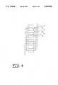
- FIG. 1shows a perspective view of one embodiment of the intramedullary nail apparatus of the invention.
- FIG. 2Ashows a diagram of the different states of a shape memory driver.
- FIG. 2Bshows a graph of length change v. temperature change for a shape memory driver.
- FIG. 3shows a schematic view of the elements of a drive assembly of the intramedullary nail apparatus of the invention.
- FIG. 4Ashows a schematic view of a push rod of the intramedullary nail apparatus of the invention.
- FIGS. 4B and 4Cshow a schematic view of a portion of a push rod having a plurality of grooves as employed in one example of the invention.
- FIG. 5shows a schematic view of a portion of a ratcheting mechanism of the intramedullary nail apparatus of the invention.
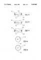
- FIGS. 6A and 6Bshow schematic views of the top and cross section of a flexible ring of the invention.
- FIG. 6Cshows a schematic view of a portion of a plurality of circular ledges of the invention.
- FIGS. 7A, 7B and 7Cshow a schematic view of an operation of a portion of the ratcheting assembly of the invention.
- FIGS. 8A and 8Bshow a schematic view of an operation of the flexible ring of the invention.
- FIGS. 9A and 9Bshow schematic views of alternate embodiments of a ratcheting assembly of the invention.
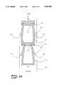
- FIG. 10shows a perspective view of one example embodiment of the invention employed within a bone.
- FIG. 11shows a block diagram of one example of how telemetry may be used to initiate lengthening events.
- FIG. 1shows a perspective view of one embodiment of the intramedullary nail apparatus of the invention.
- the apparatus of the inventionhas a housing 35 and a drive mechanism 90.
- the apparatus of the inventionis inserted into a marrow cavity 5 of a bone 8.
- the intramedullary nail 25is positioned along the length of the bone 8, allowing the housing 35 of the intramedullary nail 25 to contact the bone 8 along a portion of the inside of the cavity 5.
- the intramedullary nail 25is attached to the bone 8 by a proximal interlocking bolt 10 and distal interlocking bolts 20 on either side of the site of a corticotomy or osteotomy 30.
- the housing 35 of the intramedullary nail 25comprises an inner cylinder 40 and a telescoping outer cylinder 50, allowing for distraction in response to the impetus of the drive mechanism 90.
- a seal 45joins the inner cylinder 40 and the telescoping outer cylinder 50. The seal 45 also preserves the integrity of the intramedullary nail 25 and prevents body fluids from entering the housing 35.
- a second seal 45Amay serve as a backup to preserve the integrity of the intramedullary nail 25 if seal 45 fails. The second seal 45A may also cooperate with the seal 45 to lower the pressure differential between chambers resulting in an improved seal.
- the inner cylinder 40houses the drive mechanism 90, which comprises a push rod 60, a plurality of flexible rings 70, a plurality of circular ledges 80, and a drive assembly 90.
- the push rod 60is located within the inner cylinder 40 and passes through the drive assembly 90.
- the plurality of flexible rings 70are attached to the push rod 60.
- the drive assembly 90provides a proximal thrust to the push rod 60
- the plurality of flexible rings 70engage a plurality of circular ledges 80 attached to an inner wall of the inner cylinder 40.
- the flexible ring 70 and circular ledge 80 systemform a ratchet assembly, allowing the push rod 60 to move in a proximal direction, while prohibiting distal movements.
- the proximal end of the push rod 60forms a screw 100 that attaches the push rod 60 to an internal thread 110 fixed to the telescoping outer cylinder 50.
- the drive mechanism 90is activated, the intramedullary nail 25 is expanded and provides a suitable distraction force to the bone 8.
- telemetryinitiates lengthening events and controls activation of the drive assembly 90.
- An external transmittersends a signal to a receiver 120 enclosed in the inner cylinder 40.
- the receiver 120activates a power supply 130 also enclosed in the inner cylinder 40.
- the power supply 130supplies a current to a resistance wire 142 wrapped around the shape memory driver 150.
- the resistance wire 142heats as current is passed through it and transfers heat to the shape memory driver 150, providing for shape recovery and expansion of the shape memory driver 150.
- the shape memory driver 150serves as a resistive element in place of resistance wire 142 and the shape memory driver 150 heats up as current is passed through it.
- biasing elements 180return the shape memory driver 150 to a deformed condition. If the shape memory driver 150 is fabricated to possess two-way thermal properties, then the shape memory driver 150 automatically resets during cooling.
- the receiver 120 and the power supply 130are located in a subcutaneous packet outside of the intramedullary nail apparatus and supply current to the shape memory driver 150 by wires 140.
- Power supply 130may advantageously comprise either a battery, a capacitor, or both. If the power supply 130 comprises a capacitor, power may be transferred to the capacitor by telemetry to be stored until used. Alternatively, the battery may charge a capacitor that provides current to the shape memory driver 150.
- FIG. 2Ashows a diagram of the different states of the shape memory driver 150.
- FIG. 2Ashows the fabricated shape of the shape memory driver 150.
- the shape memory driver 150is fabricated under conditions of high temperature and low strain in a state called the austenite phase.
- the shape memory driver 150may be cooled and subjected to a strong force indicated as force 400, resulting in a state called the martensite phase and leaving the shape memory driver 150 under a high strain. After subjection to high heat, the shape memory driver 150 may regain its original shape.
- FIG. 2Bshows a graph of length change v. temperature change for the shape memory driver 150.
- the graphgenerally illustrates the correlation of property changes of the shape memory driver 150 with temperature.
- a resetting force to restore the shape memorymay or may not be needed depending on the process used to fabricate the shape memory driver 150.
- the shape memory driver 150may be advantageously fabricated to return to the martensite phase during cooling as indicated by curve 410.
- FIG. 3shows a schematic view of the elements of the drive assembly 90 of the intramedullary nail apparatus of the invention.
- the drive assembly 90comprises a shape memory driver 150, a push collar 160, a wedge gripper 170, and biasing elements 180.
- the inner cylinder 40has a distal strut 190 and proximal strut 200 that house the drive assembly 90.
- the shape memory driver 150is secured on the distal strut 190.
- the push collar 160is located above the shape memory driver 150.
- the biasing elements 180are attached to the proximal strut 190 and the push collar 160. The biasing elements 180 bias the push collar 160 toward the shape memory driver 150 to ensure stable contact with the shape memory driver 150.
- a shaft 210 of the push rod 60passes through the drive assembly 90 and through the wedge gripper 170 situated within the push collar 160.
- the biasing elements 180also attach to the wedge gripper 170 and bias the wedge gripper 170 within the push collar 160.
- the biasing force combined with the angle of the push collar 160cause the wedge gripper 170 to grip the shaft 210 of the push rod 60.
- the attachment of the wedge gripper 170 to the shaft 210 of the push rod 60forces the push rod 60 to move with the drive assembly 90.
- Telemetryactivates the shape memory driver 150.
- the shape memory driver 150forces the drive assembly 90 in a proximal direction during activation.
- the biasing elements 180act to prevent the drive assembly 90 from jamming during activation and to maintain the attachment of the wedge gripper 170 to the shaft 210 of the push rod 60.
- the proximal movement of the drive assembly 90drives the push rod 60 up through the ratchet assembly and forces a proximal movement of the outer cylinder 50, thus expanding the intramedullary nail 25 and providing an appropriate distraction.
- FIG. 4Ashows a schematic view of the push rod 60 of the intramedullary nail apparatus of the invention.
- the push rod 60has a shaft 210, a tapered section 220, a grooved shaft 230, and a screw 100.
- the shaft 210 of the push rod 60forms the distal end of the push rod 60 and is inserted within the inner cylinder 40 and passes through the drive assembly 90.
- a tapered section 220links the shaft 210 to the grooved shaft 230 and increases the diameter of the push rod 60 from the shaft 210.
- the grooved shaft 230is located on a proximal section of the push rod 60, and has a plurality of grooves 240 into which the plurality of flexible rings 70 are inserted.
- the proximal end of the push rod 60forms a screw 100.
- the screw 100attaches to the internal thread 110 of the outer cylinder 50, and forces the outer cylinder 50 to move with the push rod 60.
- FIGS. 4B and 4Cshow a schematic view of a portion of the push rod 60 having a plurality of grooves 240 as employed in one embodiment of the invention.
- the proximal section of the push rod 60include the plurality of grooves 240.
- the plurality of grooves 240accommodate insertion of the plurality of flexible rings 70.
- fabrication of the plurality of grooves 240provides for an appropriate size to allow the plurality of flexible rings 70 to flex inwardly when sliding past the plurality of circular ledges 80.
- the plurality of grooves 240also allow the plurality of flexible rings 70 to rest on the plurality of circular ledges 80 when bearing a load.
- FIG. 5shows a schematic view of a portion of the ratcheting mechanism of the intramedullary nail apparatus of the invention.
- the ratchet assemblycomprises the plurality of flexible rings 70 and the plurality of circular ledges 80.
- the plurality of flexible rings 70 and the plurality of circular ledges 80engage in a staggered manner, allowing for smaller increments of movement and precise lengthenings of the intramedullary nail 25.
- each flexible ring 70engages the plurality of circular ledges 80, each flexible ring 70 is deflected inward, as further described in FIG. 6A, 6B, and 6C. After the flexible ring 70 passes a circular ledge 80, the flexible ring 70 comes to rest in a position to bear a load.
- the plurality of circular ledges 80are spaced about 0.25 mm apart less than the spacing of the plurality of flexible rings 70, allowing for incremental displacements of about 0.25 mm.
- the plurality of ledge-ring assembliesallow for a total lengthening of about 80 mm.
- FIGS. 6A and 6Bshow a schematic view of the top and cross section of the flexible ring 70 of the invention.
- the flexible ring 70is made from a flexible material and has an upper half 300 and a lower half 310.
- the flexible materialmay be a flexible material known to be suitable for use in implantable devices. Such materials are known in the art.
- the upper half 300 and the lower half 310have an upper radius 305 and a lower radius 315.
- the lower half 310 of the flexible ring 70also has a gap 320.
- the lower radius 315is larger than the upper radius 305 and is separated from the upper radius by an offset 330.
- the upper radius 305is formed to fit tightly around the plurality of grooves 240 in the push rod 60.
- the offset 330 and the larger lower radius 315allow the lower half 315 of the flexible ring 70 to fit loosely around the plurality of grooves 240 in the push rod 60.
- the side viewshows that the flexible ring 70 has a taper 340.
- the taper 340provides a sliding surface for the flexible ring 70 and provides an inward force on the flexible ring 70 as the flexible ring 70 is moved upwards.
- the offset 330 and the larger lower radius 315allow the flexible ring 70 to deflect inward and narrow the gap 320, decreasing the diameter of the flexible ring 70, and allowing the flexible ring 70 to pass the circular ledge 80.
- FIG. 6Cshows a schematic view of a portion of the plurality of circular ledges 80 of the invention.
- the plurality of circular ledges 80is fixed to an inner wall of the inner cylinder 40.
- the plurality of circular ledges 80is arranged so that the plurality of circular ledges 80 engage the plurality of flexible rings 70 in a staggered fashion.
- the plurality of circular ledges 80have a taper 350, approximately equivalent to the taper 340 of the flexible ring 70. When engaged, the taper 340 provides for an inward force on the flexible ring 70 for inward deflection.
- FIGS. 7A, 7B and 7Cshow a schematic view of the operation of a portion of the ratcheting assembly of the invention.
- the ratcheting assemblyhas a plurality of flexible rings 70, a push rod 60, and a plurality of circular ledges 80.
- the plurality of flexible rings 70is affixed to the push rod 60 within a plurality of grooves 240.
- the plurality of circular ledges 80are fixed to the inner wall on the inner cylinder 40.
- the plurality of flexible rings 70engage the plurality of circular ledges 80.
- FIG. 7Ashows the flexible ring 70 while unengaged with the circular ledge 80 in a free sliding state.
- FIG. 7Bshows the flexible ring 70 while sliding past the circular ledge 80 in an inward deflection state.
- the taper 340 of the flexible ring 70 and the taper 350 of the circular ledge 80act to induce the inward deflection state.
- FIG. 7Cshows the flexible ring 70 resting on the circular ledge 80 in a position to assume a weight bearing load.
- FIG. 8A and 8Bshow a schematic view of the operation of the flexible ring 70 of the invention.
- FIG. 8Ashows a first diameter d1 of the flexible ring 70 when in the free sliding state or when resting on the circular ledge 80.
- FIG. 8Bshows a second diameter d2 of the flexible ring 70 when in the full inward deflected state. The smaller second diameter d2 of the inward deflected state allows the flexible ring 70 to deflect past the circular ledge 80.
- FIGS. 9A and 9Bshow schematic views of alternate embodiments of the ratcheting assembly of the invention.
- FIG. 9Ashows a schematic view of a cantilever flexible rod ratchet system.
- the ratcheting assemblyhas a plurality of flexible hooks 75 engaging a plurality of circular ledges 80.
- the plurality of flexible hooks 75comprise a series of separate elements linked top to bottom.
- the top of each elementcomprises a hook 77, and the bottom of each element comprises a catch 79.
- the hook 77 of each element of the plurality of flexible hooks 75is connected to the catch 79 of each next element.
- each element of the plurality of flexible hooks 75has a taper 73.
- the taper 73promotes the deflection of each element of the plurality of flexible hooks 75 past the plurality of circular ledges 80. During deflection, the hook end 77 of the element deflects inward.
- the plurality of flexible hooks 75attach at a distal end to the shaft 210 of the push rod 60 driven by the drive assembly 90.
- the plurality of flexible hooks 75attach at a proximal end to the telescoping outer cylinder 50 by the screw 100.
- the plurality of circular ledges 80are attached to the inner wall of the inner cylinder 40.
- the plurality of flexible hooks 75engage the plurality of circular ledges 80 and regulate the expansion of the intramedullary nail 25 similarly to the ratcheting mechanism of the plurality of flexible rings 70.
- each of the plurality of flexible hooks 75is a separate element, allowing the plurality of flexible hooks 75 to be individually flexible, and to accommodate curves.
- FIG. 9Bshows a schematic view of a fixed end flexible rod ratcheting system.
- the fixed end flexible rod ratcheting systemhas a flexible rod 420 having a plurality of hooks 430.
- the plurality of hooks 430engage a plurality of circular ledges 432 mounted on an inner wall of an inner cylinder 40 in a staggered pattern.
- the flexible rod 420has a plurality of cavities 434 that promote deflection by bending inward during axial displacement, allowing the plurality of hooks 430 to move past the plurality of circular ledges 432.
- FIG. 10shows a perspective view of one example embodiment of the invention as employed within a bone 8.
- the intramedullary nail 25is attached to the bone 8 by a proximal interlocking bolt 10 and distal interlocking bolts 20.
- An inner cylinder 40 and a telescoping outer cylinder 50form the housing 35 of the intramedullary nail 25.
- a seal 45seals the housing 35 preventing body fluids from entering the intramedullary nail 25, while allowing for expansion of the intramedullary nail 25.
- the outer cylinder 40contacts the bone 8 along an isthmus 47 providing for improved stability.
- the inner cylinder 40, the telescoping outer cylinder 50, and the seal 45form an sealed unit having no external connections.
- the bone 8is cut at corticotomy site 30, allowing for expansion of the intramedullary nail 25, and distraction of the bone 8.
- FIG. 11shows a block diagram of one example of how telemetry may be used to initiate lengthening events.
- the inventionhas a telemetry apparatus 122 for sending a signal 124.
- a receiver 120senses the signal 124 and initiates a lengthening event.
- Such telemetry units and receiversare commercially available and may be adapted for use with the present invention.
Landscapes
- Health & Medical Sciences (AREA)
- Orthopedic Medicine & Surgery (AREA)
- Surgery (AREA)
- Life Sciences & Earth Sciences (AREA)
- Heart & Thoracic Surgery (AREA)
- Nuclear Medicine, Radiotherapy & Molecular Imaging (AREA)
- Engineering & Computer Science (AREA)
- Biomedical Technology (AREA)
- Neurology (AREA)
- Medical Informatics (AREA)
- Molecular Biology (AREA)
- Animal Behavior & Ethology (AREA)
- General Health & Medical Sciences (AREA)
- Public Health (AREA)
- Veterinary Medicine (AREA)
- Surgical Instruments (AREA)
Abstract
Description
______________________________________ NAME YEAR DRIVE MECHANISM ______________________________________ Witt, et al. 1978 Electric Motor Bliskunov 1984 Hip Rotation Herzenberg, et al. 1989 N/A Verkerke, et al. 1989 Electric Motor (endoprosthesis) Betz, et al. 1990 Electric Motor Fisher, et al. 1992 Electric Motor Guichet, et al. 1991 Hip Rotation Hellend 1992 Leg Rotation Pursley, et al. 1992 Digital Motor ______________________________________
Claims (45)
Priority Applications (1)
| Application Number | Priority Date | Filing Date | Title |
|---|---|---|---|
| US08/178,882US5415660A (en) | 1994-01-07 | 1994-01-07 | Implantable limb lengthening nail driven by a shape memory alloy |
Applications Claiming Priority (1)
| Application Number | Priority Date | Filing Date | Title |
|---|---|---|---|
| US08/178,882US5415660A (en) | 1994-01-07 | 1994-01-07 | Implantable limb lengthening nail driven by a shape memory alloy |
Publications (1)
| Publication Number | Publication Date |
|---|---|
| US5415660Atrue US5415660A (en) | 1995-05-16 |
Family
ID=22654291
Family Applications (1)
| Application Number | Title | Priority Date | Filing Date |
|---|---|---|---|
| US08/178,882Expired - LifetimeUS5415660A (en) | 1994-01-07 | 1994-01-07 | Implantable limb lengthening nail driven by a shape memory alloy |
Country Status (1)
| Country | Link |
|---|---|
| US (1) | US5415660A (en) |
Cited By (163)
| Publication number | Priority date | Publication date | Assignee | Title |
|---|---|---|---|---|
| US5575790A (en)* | 1995-03-28 | 1996-11-19 | Rensselaer Polytechnic Institute | Shape memory alloy internal linear actuator for use in orthopedic correction |
| US5626581A (en)* | 1995-11-27 | 1997-05-06 | Volunteers For Medical Engineering | Implantable bone lengthening apparatus |
| US5626579A (en)* | 1993-02-12 | 1997-05-06 | The Cleveland Clinic Foundation | Bone transport and lengthening system |
| US5704938A (en)* | 1996-03-27 | 1998-01-06 | Volunteers For Medical Engineering | Implantable bone lengthening apparatus using a drive gear mechanism |
| NL1004873C2 (en)* | 1996-12-23 | 1998-06-24 | Univ Twente | Device for moving two objects together. |
| WO1998030163A1 (en)* | 1997-01-07 | 1998-07-16 | Wittenstein Motion Control Gmbh | Distraction device for moving apart two bone sections |
| US5827286A (en)* | 1997-02-14 | 1998-10-27 | Incavo; Stephen J. | Incrementally adjustable tibial osteotomy fixation device and method |
| WO1998047438A1 (en)* | 1997-04-24 | 1998-10-29 | Augustin Betz | Bone traction device |
| US5858020A (en)* | 1995-12-05 | 1999-01-12 | Metagen, Llc | Modular prosthesis |
| EP0919717A1 (en)* | 1997-11-27 | 1999-06-02 | Fachhochschule Konstanz | Actuator having shape memory alloy element and use |
| GB2333457A (en)* | 1998-01-23 | 1999-07-28 | Andrew Charalambous | Extendible arm including magneto-strictive element |
| US5961553A (en)* | 1995-02-13 | 1999-10-05 | Medinov-Amp | Long bone elongation device |
| DE19829523A1 (en)* | 1998-07-02 | 2000-01-05 | Michael Butsch | Distraction device for moving apart a one- or two-part, possibly separate bone |
| US6033412A (en)* | 1997-04-03 | 2000-03-07 | Losken; H. Wolfgang | Automated implantable bone distractor for incremental bone adjustment |
| US20020022856A1 (en)* | 2000-08-14 | 2002-02-21 | Wesley Johnson | Transverse cavity device and method |
| US6383185B1 (en)* | 1999-03-01 | 2002-05-07 | Rainer Baumgart | Medullary nail for the distraction of bones |
| WO2002071962A1 (en)* | 2001-03-13 | 2002-09-19 | Soubeiran Arnaud Andre | Device for moving one bone portion in relation to another in one direction along a given axis |
| US6530927B2 (en)* | 1998-08-20 | 2003-03-11 | Volunteers For Medical Engineering | Bone cutting and breaking apparatus, and miniaturized cutting head |
| US20030120273A1 (en)* | 2001-12-21 | 2003-06-26 | Cole J. Dean | Surgical distractor frame |
| US6722360B2 (en) | 2000-06-16 | 2004-04-20 | Rajiv Doshi | Methods and devices for improving breathing in patients with pulmonary disease |
| US6755862B2 (en)* | 2000-01-03 | 2004-06-29 | Orthoscope Ltd. | Intramedullary support strut |
| US20040152970A1 (en)* | 2003-01-30 | 2004-08-05 | Mark Hunter | Six degree of freedom alignment display for medical procedures |
| US20040204717A1 (en)* | 2003-04-09 | 2004-10-14 | Jonathan Fanger | Guide for spinal tools, implants, and devices |
| US20040204710A1 (en)* | 2003-04-09 | 2004-10-14 | Tushar Patel | Drill guide and plate inserter |
| US20040204712A1 (en)* | 2003-04-09 | 2004-10-14 | Eric Kolb | Bone fixation plates |
| US20040243038A1 (en)* | 2001-08-06 | 2004-12-02 | Noble Patterson | Walking aid |
| US20050010233A1 (en)* | 2001-11-19 | 2005-01-13 | Manfred Wittenstein | Distraction device |
| US20050059970A1 (en)* | 2003-09-17 | 2005-03-17 | Eric Kolb | Bone fixation systems |
| EP1582161A1 (en)* | 2004-03-31 | 2005-10-05 | Orthofix International B.V. | Intramedullary nail provided with expansion fixing means operated by one or more driving elements |
| US20050240190A1 (en)* | 2004-04-21 | 2005-10-27 | Gall Kenneth A | Osteosynthetic implants and methods of use and manufacture |
| US20060004459A1 (en)* | 2004-06-30 | 2006-01-05 | Hazebrouck Stephen A | Adjustable orthopaedic prosthesis and associated method |
| US20060015123A1 (en)* | 2004-07-15 | 2006-01-19 | Wright Medical Technology, Inc. | Guide assembly for intramedullary fixation and method of using the same |
| US20060015101A1 (en)* | 2004-07-15 | 2006-01-19 | Wright Medical Technology, Inc. | Intramedullary fixation assembly and devices and methods for installing the same |
| US20060069447A1 (en)* | 2004-09-30 | 2006-03-30 | Disilvestro Mark R | Adjustable, remote-controllable orthopaedic prosthesis and associated method |
| WO2006041460A1 (en)* | 2004-10-04 | 2006-04-20 | Saint Louis University | Intramedullary nail device and method for repairing long bone |
| US20060144398A1 (en)* | 2004-12-08 | 2006-07-06 | Rajiv Doshi | Respiratory devices |
| US20060155279A1 (en)* | 2004-10-28 | 2006-07-13 | Axial Biotech, Inc. | Apparatus and method for concave scoliosis expansion |
| US20060200144A1 (en)* | 2000-09-22 | 2006-09-07 | Warburton Mark J | Intramedullary interlocking fixation devices for the distal radius |
| US20060235424A1 (en)* | 2005-04-01 | 2006-10-19 | Foster-Miller, Inc. | Implantable bone distraction device and method |
| US20060293683A1 (en)* | 2003-04-16 | 2006-12-28 | Roman Stauch | Device for lengthening bones or bone parts |
| EP1764050A3 (en)* | 2005-09-20 | 2007-07-04 | HAVITCIOGLU, Hasan | Intramedullary fixation pin |
| US20070270855A1 (en)* | 2006-04-06 | 2007-11-22 | Lotus Medical, Llc | Active compression to facilitate healing of bones |
| WO2007139890A2 (en) | 2006-05-23 | 2007-12-06 | Ventus Medical, Inc. | Nasal respiratory devices |
| US20080041373A1 (en)* | 2006-06-07 | 2008-02-21 | Ventus Medical, Inc. | Nasal devices |
| US20080051779A1 (en)* | 2006-08-02 | 2008-02-28 | The Nemours Foundation | Force-controlled autodistraction |
| US20080142018A1 (en)* | 2006-11-16 | 2008-06-19 | Ventus Medical, Inc. | Nasal device applicators |
| US20080177319A1 (en)* | 2006-12-09 | 2008-07-24 | Helmut Schwab | Expansion Rod, Self-Adjusting |
| WO2008057480A3 (en)* | 2006-11-06 | 2008-07-31 | Janet Conway | Internal bone transport |
| US20080195224A1 (en)* | 2007-02-09 | 2008-08-14 | Teitelbaum Daniel H | Mechanical extension implants for short bowel syndrome |
| US20080207983A1 (en)* | 2007-02-22 | 2008-08-28 | Searete Llc, A Limited Liability Corporation Of The State Of Delaware | Coded-sequence activation of surgical implants |
| US20080262495A1 (en)* | 2004-03-31 | 2008-10-23 | Orthofix S.R.L | Intramedullary Nail Comprising Elements of Shape-Memory Material |
| US20080287951A1 (en)* | 2007-03-22 | 2008-11-20 | Stoneburner James D | Segmented intramedullary structure |
| WO2008007378A3 (en)* | 2006-07-12 | 2009-04-16 | Intramed Systems Ltd | Intramedullar distraction device with user actuated distraction |
| US7542791B2 (en) | 2003-01-30 | 2009-06-02 | Medtronic Navigation, Inc. | Method and apparatus for preplanning a surgical procedure |
| US20090145441A1 (en)* | 2007-12-06 | 2009-06-11 | Rajiv Doshi | Delayed resistance nasal devices and methods of use |
| US20090145788A1 (en)* | 2007-12-05 | 2009-06-11 | Rajiv Doshi | Packaging and dispensing nasal devices |
| US20090157077A1 (en)* | 2007-12-17 | 2009-06-18 | Wright Medical Technology, Inc. | Guide assembly for intramedullary fixation and method of using the same |
| US20090240339A1 (en)* | 2007-02-09 | 2009-09-24 | Teitelbaum Daniel H | Mechanical extension implants for short bowel syndrome |
| WO2009115645A1 (en)* | 2008-03-19 | 2009-09-24 | Helsinki University Of Technology | Internal osteodistraction device |
| WO2010050891A1 (en) | 2008-10-31 | 2010-05-06 | Teslux Holding S.A. | Device and method for bone adjustment operating with wireless transmission energy |
| KR100959186B1 (en) | 2008-02-14 | 2010-05-24 | 이순혁 | Long bone / tibia distraction device with linear actuator |
| US20100145138A1 (en)* | 2000-02-10 | 2010-06-10 | Obtech Medical Ag | Urinary incontinence treatment with wireless energy supply |
| US7806120B2 (en) | 2004-12-08 | 2010-10-05 | Ventus Medical, Inc. | Nasal respiratory devices for positive end-expiratory pressure |
| US20100262160A1 (en)* | 2009-04-14 | 2010-10-14 | Searete Llc, A Limited Liability Corporation Of The State Of Delaware | Adjustable orthopedic implant and method for treating an orthopedic condition in a subject |
| US7846162B2 (en) | 2005-05-18 | 2010-12-07 | Sonoma Orthopedic Products, Inc. | Minimally invasive actuable bone fixation devices |
| US7909848B2 (en) | 2003-06-27 | 2011-03-22 | Depuy Spine, Inc. | Tissue retractor and guide device |
| US7909825B2 (en) | 2006-11-22 | 2011-03-22 | Sonoma Orthepedic Products, Inc. | Fracture fixation device, tools and methods |
| US7909829B2 (en) | 2003-06-27 | 2011-03-22 | Depuy Spine, Inc. | Tissue retractor and drill guide |
| US7931651B2 (en) | 2006-11-17 | 2011-04-26 | Wake Lake University Health Sciences | External fixation assembly and method of use |
| US7935123B2 (en) | 2003-04-09 | 2011-05-03 | Depuy Acromed, Inc. | Drill guide with alignment feature |
| US7942931B2 (en) | 2002-02-21 | 2011-05-17 | Spiration, Inc. | Device and method for intra-bronchial provision of a therapeutic agent |
| US20110137347A1 (en)* | 2009-12-01 | 2011-06-09 | Synthes Usa, Llc | Non-fusion scoliosis expandable spinal rod |
| US20110144756A1 (en)* | 2009-10-10 | 2011-06-16 | Bickley Barry T | Method and apparatus for restoring a joint, including the provision and use of a longitudinally-adjustable and rotationally-adjustable joint prosthesis |
| US8021385B2 (en) | 2002-03-20 | 2011-09-20 | Spiration, Inc. | Removable anchored lung volume reduction devices and methods |
| US8043301B2 (en) | 2007-10-12 | 2011-10-25 | Spiration, Inc. | Valve loader method, system, and apparatus |
| US8061357B2 (en) | 2004-12-08 | 2011-11-22 | Ventus Medical, Inc. | Adhesive nasal respiratory devices |
| WO2011148047A1 (en) | 2010-05-24 | 2011-12-01 | Aalto University Foundation | Implantable treatment device fixed or interlinked to bone |
| US8079368B2 (en) | 2003-04-08 | 2011-12-20 | Spiration, Inc. | Bronchoscopic lung volume reduction method |
| US8096938B2 (en) | 1999-08-12 | 2012-01-17 | Obtech Medical Ag | Controlled anal incontinence disease treatment |
| US8126558B2 (en) | 2000-02-14 | 2012-02-28 | Obtech Medical Ag | Controlled penile prosthesis |
| US8136230B2 (en) | 2007-10-12 | 2012-03-20 | Spiration, Inc. | Valve loader method, system, and apparatus |
| US20120083820A1 (en)* | 2009-04-22 | 2012-04-05 | The Regents Of The University Of California | Expandable distension device for hollow organ growth |
| US20120165950A1 (en)* | 2010-12-23 | 2012-06-28 | Rainer Baumgart | Implantable prosthesis for replacing a human hip or knee joint and the adjoining bone sections |
| US8216398B2 (en) | 2010-05-17 | 2012-07-10 | Saint Louis University | Method for controlling phase transformation temperature in metal alloy of a device |
| US8290594B2 (en) | 2000-02-11 | 2012-10-16 | Obtech Medical Ag | Impotence treatment apparatus with energy transforming means |
| US8287541B2 (en) | 2005-05-18 | 2012-10-16 | Sonoma Orthopedic Products, Inc. | Fracture fixation device, tools and methods |
| US8287538B2 (en) | 2008-01-14 | 2012-10-16 | Conventus Orthopaedics, Inc. | Apparatus and methods for fracture repair |
| US8287444B2 (en) | 2000-02-10 | 2012-10-16 | Obtech Medical Ag | Mechanical impotence treatment apparatus |
| US8313423B2 (en) | 2000-02-14 | 2012-11-20 | Peter Forsell | Hydraulic anal incontinence treatment |
| US8377016B2 (en) | 2007-01-10 | 2013-02-19 | Wake Forest University Health Sciences | Apparatus and method for wound treatment employing periodic sub-atmospheric pressure |
| CN103054638A (en)* | 2013-01-05 | 2013-04-24 | 曾融生 | Memory alloy distractor |
| US8454708B2 (en) | 2006-03-31 | 2013-06-04 | Spiration, Inc. | Articulable anchor |
| US8460293B2 (en) | 2010-12-31 | 2013-06-11 | Orthofix S.R.L. | Intramedullary nail with shape memory elements for elongated bones |
| US20130197656A1 (en)* | 2012-02-01 | 2013-08-01 | Zimmer, Inc. | Adjustable provisional component of a medical device |
| US8509894B2 (en) | 2008-10-10 | 2013-08-13 | Milux Holding Sa | Heart help device, system, and method |
| US8545384B2 (en) | 1999-08-12 | 2013-10-01 | Obtech Medical Ag | Anal incontinence disease treatment with controlled wireless energy supply |
| US8556796B2 (en) | 2000-02-10 | 2013-10-15 | Obtech Medical Ag | Controlled urinary incontinence treatment |
| US8600510B2 (en) | 2008-10-10 | 2013-12-03 | Milux Holding Sa | Apparatus, system and operation method for the treatment of female sexual dysfunction |
| US8636809B2 (en) | 2008-01-29 | 2014-01-28 | Milux Holding Sa | Device for treating obesity |
| CN103648417A (en)* | 2011-05-16 | 2014-03-19 | 史密夫和内修有限公司 | Measuring skeletal distraction |
| US8678997B2 (en) | 2000-02-14 | 2014-03-25 | Obtech Medical Ag | Male impotence prosthesis apparatus with wireless energy supply |
| US8696745B2 (en) | 2008-10-10 | 2014-04-15 | Kirk Promotion Ltd. | Heart help device, system, and method |
| WO2014075025A1 (en)* | 2012-11-12 | 2014-05-15 | Ziran Navid | Dynamic axial nail for intramedullary treatment of long bone fractures |
| US8734318B2 (en) | 2000-02-11 | 2014-05-27 | Obtech Medical Ag | Mechanical anal incontinence |
| US8764627B2 (en) | 2000-02-14 | 2014-07-01 | Obtech Medical Ag | Penile prosthesis |
| US8795241B2 (en) | 2011-05-13 | 2014-08-05 | Spiration, Inc. | Deployment catheter |
| WO2014128349A1 (en)* | 2013-02-22 | 2014-08-28 | Synoste Oy | Actuator and method for improving an actuator |
| US20140243825A1 (en)* | 2011-02-17 | 2014-08-28 | Mylad Orthopedic Solutions LLC | Compressible device assembly and associated method for facilitating healing between bones |
| US8874215B2 (en) | 2008-10-10 | 2014-10-28 | Peter Forsell | System, an apparatus, and a method for treating a sexual dysfunctional female patient |
| US8875711B2 (en) | 2010-05-27 | 2014-11-04 | Theravent, Inc. | Layered nasal respiratory devices |
| US8906022B2 (en) | 2010-03-08 | 2014-12-09 | Conventus Orthopaedics, Inc. | Apparatus and methods for securing a bone implant |
| US8961518B2 (en) | 2010-01-20 | 2015-02-24 | Conventus Orthopaedics, Inc. | Apparatus and methods for bone access and cavity preparation |
| US8961567B2 (en) | 2010-11-22 | 2015-02-24 | DePuy Synthes Products, LLC | Non-fusion scoliosis expandable spinal rod |
| US8961516B2 (en) | 2005-05-18 | 2015-02-24 | Sonoma Orthopedic Products, Inc. | Straight intramedullary fracture fixation devices and methods |
| US8961448B2 (en) | 2008-01-28 | 2015-02-24 | Peter Forsell | Implantable drainage device |
| US8974484B2 (en) | 2001-09-11 | 2015-03-10 | Spiration, Inc. | Removable lung reduction devices, systems, and methods |
| US8974527B2 (en) | 2003-08-08 | 2015-03-10 | Spiration, Inc. | Bronchoscopic repair of air leaks in a lung |
| US8986336B2 (en) | 2001-10-25 | 2015-03-24 | Spiration, Inc. | Apparatus and method for deployment of a bronchial obstruction device |
| US9060820B2 (en) | 2005-05-18 | 2015-06-23 | Sonoma Orthopedic Products, Inc. | Segmented intramedullary fracture fixation devices and methods |
| US9155574B2 (en) | 2006-05-17 | 2015-10-13 | Sonoma Orthopedic Products, Inc. | Bone fixation device, tools and methods |
| US20150289910A1 (en)* | 2014-04-12 | 2015-10-15 | Seyed Alireza Mirghasemi | Modular bone plate |
| US9615962B2 (en) | 2006-05-23 | 2017-04-11 | Jean-Pierre Robitaille | Nasal cannula |
| US9730830B2 (en) | 2011-09-29 | 2017-08-15 | Trudell Medical International | Nasal insert and cannula and methods for the use thereof |
| US9730739B2 (en) | 2010-01-15 | 2017-08-15 | Conventus Orthopaedics, Inc. | Rotary-rigid orthopaedic rod |
| US9770278B2 (en) | 2014-01-17 | 2017-09-26 | Arthrex, Inc. | Dual tip guide wire |
| US9814499B2 (en) | 2014-09-30 | 2017-11-14 | Arthrex, Inc. | Intramedullary fracture fixation devices and methods |
| US9827025B2 (en) | 2015-11-20 | 2017-11-28 | Globus Medical, Inc. | Expandable intramedullary systems and methods of using the same |
| US9833354B2 (en) | 2004-12-08 | 2017-12-05 | Theravent, Inc. | Nasal respiratory devices |
| CN107518961A (en)* | 2017-08-18 | 2017-12-29 | 上海微创医疗器械(集团)有限公司 | Prosthesis and prosthesis system |
| US20180064475A1 (en)* | 2015-04-29 | 2018-03-08 | Tst Rakor Ve Tibbì Aletler Sanayì Ve Tìcaret Lìmìted Sìrketì | Telescopic nail |
| WO2018060235A1 (en)* | 2016-09-30 | 2018-04-05 | Fraunhofer-Gesellschaft zur Förderung der angewandten Forschung e.V. | Implant having a movable implant component |
| US9949812B2 (en) | 2009-07-17 | 2018-04-24 | Peter Forsell | Vaginal operation method for the treatment of anal incontinence in women |
| US9974581B2 (en) | 2015-11-20 | 2018-05-22 | Globus Medical, Inc. | Expandable intramedullary systems and methods of using the same |
| CN108143477A (en)* | 2017-12-18 | 2018-06-12 | 武汉大学 | Using the intramedullary bone lengthening device of memory alloy spring electromagnetic heating |
| US10022132B2 (en) | 2013-12-12 | 2018-07-17 | Conventus Orthopaedics, Inc. | Tissue displacement tools and methods |
| US10092333B2 (en) | 2015-11-20 | 2018-10-09 | Globus Medical, Inc. | Expandable intramedullary systems and methods of using the same |
| US10117738B2 (en) | 2015-01-23 | 2018-11-06 | The Regents Of The University Of Michigan | Atraumatic tip geometry for indwelling devices |
| US10136929B2 (en) | 2015-07-13 | 2018-11-27 | IntraFuse, LLC | Flexible bone implant |
| US10154863B2 (en) | 2015-07-13 | 2018-12-18 | IntraFuse, LLC | Flexible bone screw |
| US10159486B2 (en) | 2014-05-21 | 2018-12-25 | The Regents Of The University Of Michigan | Fenestrated decoupling system for internal selective attachment to soft tissue organs |
| US10194946B2 (en) | 2015-01-26 | 2019-02-05 | Panther Orthopedics, Inc. | Active tension bone and joint stabilization methods |
| US10219898B2 (en) | 2008-10-10 | 2019-03-05 | Peter Forsell | Artificial valve |
| US10485595B2 (en) | 2015-07-13 | 2019-11-26 | IntraFuse, LLC | Flexible bone screw |
| US10499960B2 (en) | 2015-07-13 | 2019-12-10 | IntraFuse, LLC | Method of bone fixation |
| CN110584841A (en)* | 2019-09-30 | 2019-12-20 | 北京爱康宜诚医疗器材有限公司 | Extendable prosthesis |
| CN110584842A (en)* | 2019-09-30 | 2019-12-20 | 北京爱康宜诚医疗器材有限公司 | Extendable prosthesis |
| US10610228B2 (en) | 2004-12-08 | 2020-04-07 | Theravent, Inc. | Passive nasal peep devices |
| US10918426B2 (en) | 2017-07-04 | 2021-02-16 | Conventus Orthopaedics, Inc. | Apparatus and methods for treatment of a bone |
| US10952836B2 (en) | 2009-07-17 | 2021-03-23 | Peter Forsell | Vaginal operation method for the treatment of urinary incontinence in women |
| CN112674912A (en)* | 2020-12-30 | 2021-04-20 | 北京爱康宜诚医疗器材有限公司 | Long bone lengthening prosthesis |
| US11033308B2 (en) | 2017-08-09 | 2021-06-15 | Panther Orthopedics, Inc. | Active bone and joint stabilization device features |
| US11045225B2 (en) | 2019-04-23 | 2021-06-29 | Panther Orthopedics, Inc. | Strength and fatigue life improvements for active bone and joint stabilization devices |
| US11123171B2 (en) | 2008-10-10 | 2021-09-21 | Peter Forsell | Fastening means for implantable medical control assembly |
| US11160588B2 (en) | 2016-05-27 | 2021-11-02 | Bala Sundararajan | System for stabilizing or lengthening bone |
| US11317956B1 (en) | 2021-08-26 | 2022-05-03 | University Of Utah Research Foundation | Active compression bone screw |
| US11426220B2 (en) | 2017-10-11 | 2022-08-30 | Howmedica Osteonics Corp. | Humeral fixation plate guides |
| US20220287745A1 (en)* | 2019-08-20 | 2022-09-15 | Orthofix S.R.L. | Intramedullary nail for distracting a long bone |
| US11596419B2 (en) | 2017-03-09 | 2023-03-07 | Flower Orthopedics Corporation | Plating depth gauge and countersink instrument |
| JP2023124853A (en)* | 2022-02-25 | 2023-09-06 | グローバス メディカル インコーポレイティッド | Implantable osteodistraction device |
| US11766278B2 (en) | 2017-11-30 | 2023-09-26 | Nuvasive, Inc. | Implantable distraction device |
| US11998255B1 (en) | 2023-08-26 | 2024-06-04 | University Of Utah Research Foundation | Cannulated continuous compression screw |
| US20250082377A1 (en)* | 2023-12-12 | 2025-03-13 | The Fourth Medical Center Of The Chinese People's Liberation Army General Hospital | Proximal-femur intraosseous release device |
| WO2025132431A1 (en)* | 2023-12-22 | 2025-06-26 | Universität des Saarlandes, Körperschaft des öffentlichen Rechts | Linear positioning element with variable setting of rigidity |
Citations (9)
| Publication number | Priority date | Publication date | Assignee | Title |
|---|---|---|---|---|
| US4262665A (en)* | 1979-06-27 | 1981-04-21 | Roalstad W L | Intramedullary compression device |
| WO1991000065A1 (en)* | 1989-07-04 | 1991-01-10 | Rainer Baumgart | Medullary nail |
| US5059193A (en)* | 1989-11-20 | 1991-10-22 | Spine-Tech, Inc. | Expandable spinal implant and surgical method |
| US5074882A (en)* | 1988-06-09 | 1991-12-24 | Medinov Sarl | Progressive elongation centro-medullar nail |
| US5156605A (en)* | 1990-07-06 | 1992-10-20 | Autogenesis Corporation | Automatic internal compression-distraction-method and apparatus |
| US5169597A (en)* | 1989-12-21 | 1992-12-08 | Davidson James A | Biocompatible low modulus titanium alloy for medical implants |
| US5180380A (en)* | 1989-03-08 | 1993-01-19 | Autogenesis Corporation | Automatic compression-distraction-torsion method and apparatus |
| US5190546A (en)* | 1983-10-14 | 1993-03-02 | Raychem Corporation | Medical devices incorporating SIM alloy elements |
| US5275599A (en)* | 1986-08-11 | 1994-01-04 | Zbikowski Juan L | Biocompression external fixator for osteosynthesis |
- 1994
- 1994-01-07USUS08/178,882patent/US5415660A/ennot_activeExpired - Lifetime
Patent Citations (10)
| Publication number | Priority date | Publication date | Assignee | Title |
|---|---|---|---|---|
| US4262665A (en)* | 1979-06-27 | 1981-04-21 | Roalstad W L | Intramedullary compression device |
| US5190546A (en)* | 1983-10-14 | 1993-03-02 | Raychem Corporation | Medical devices incorporating SIM alloy elements |
| US5275599A (en)* | 1986-08-11 | 1994-01-04 | Zbikowski Juan L | Biocompression external fixator for osteosynthesis |
| US5074882A (en)* | 1988-06-09 | 1991-12-24 | Medinov Sarl | Progressive elongation centro-medullar nail |
| US5180380A (en)* | 1989-03-08 | 1993-01-19 | Autogenesis Corporation | Automatic compression-distraction-torsion method and apparatus |
| WO1991000065A1 (en)* | 1989-07-04 | 1991-01-10 | Rainer Baumgart | Medullary nail |
| US5263955A (en)* | 1989-07-04 | 1993-11-23 | Rainer Baumgart | Medullary nail |
| US5059193A (en)* | 1989-11-20 | 1991-10-22 | Spine-Tech, Inc. | Expandable spinal implant and surgical method |
| US5169597A (en)* | 1989-12-21 | 1992-12-08 | Davidson James A | Biocompatible low modulus titanium alloy for medical implants |
| US5156605A (en)* | 1990-07-06 | 1992-10-20 | Autogenesis Corporation | Automatic internal compression-distraction-method and apparatus |
Non-Patent Citations (45)
| Title |
|---|
| Anderson, W. V., "Leg Lengthening", The Journal of Bone and Joint Surgery, p. 150. |
| Anderson, W. V., Leg Lengthening , The Journal of Bone and Joint Surgery, p. 150.* |
| Baumann, F., J. Harms, "Der Verlangerungsnagel", Archiv fur Orthopadische und Unfall-Chirurgie, 90, 139-146 (1977), J. F. Bergmann-Verlag 1977. |
| Baumann, F., J. Harms, Der Verlangerungsnagel , Archiv fur Orthopadische und Unfall Chirurgie, 90, 139 146 (1977), J. F. Bergmann Verlag 1977.* |
| Betz, A., R. Baumgart, L. Schweiberer, "Erstes Voll Implantierbares Intramedullares System zur Callusdistraktion-Marknagel mit Programmierbarem Antrieb zur Beinverlangerung und Segmentverschiebung", Der Chirurg, (1990) 61:605-609, Springer-Verlag 1990 (Rough partial translation attached). |
| Betz, A., R. Baumgart, L. Schweiberer, Erstes Voll Implantierbares Intramedullares System zur Callusdistraktion Marknagel mit Programmierbarem Antrieb zur Beinverlangerung und Segmentverschiebung , Der Chirurg, (1990) 61:605 609, Springer Verlag 1990 (Rough partial translation attached).* |
| Bliskunov, A., "An Implantable Apparatus for Lengthening the Femur Without External Drive", N. N. Priorov Central Research Institute of Traumatology and Orthopedics, Moscow. Crimean Medical Institute, Simferopol. Translated from Meditsinskaya Tekhnika, No. 2, pp. 44-49, Mar.-Apr., 1984, copyright 1984 Plenum Publishing Corporation, pp. 71-76. |
| Bliskunov, A., "Clinical Results of the Lengthening of the Extremity With Fully Implantable Apparatus". |
| Bliskunov, A., An Implantable Apparatus for Lengthening the Femur Without External Drive , N. N. Priorov Central Research Institute of Traumatology and Orthopedics, Moscow. Crimean Medical Institute, Simferopol. Translated from Meditsinskaya Tekhnika, No. 2, pp. 44 49, Mar. Apr., 1984, copyright 1984 Plenum Publishing Corporation, pp. 71 76.* |
| Bliskunov, A., Clinical Results of the Lengthening of the Extremity With Fully Implantable Apparatus .* |
| DeBastiani, Giovanni, et al., "Limb Lengthening by Callus Distraction (Callotasis)", Journal of Pediatric Orthopedics, 7:2 (1987), pp. 129-134. |
| DeBastiani, Giovanni, et al., Limb Lengthening by Callus Distraction (Callotasis) , Journal of Pediatric Orthopedics, 7:2 (1987), pp. 129 134.* |
| Fischer, Carol, William Mackenzie, Robert Meet, Graham Pate, Alastair Younger, Martine Breault, Personal Communication dated Feb. 15, 1992 to Mike Campbell from Carol Fisher, with attachments (7 pages).* |
| Gotz, J. and W. D. Schellmann, "Kontinuierliche Verlangerung des Femur bei Intramedullarer Stabilisicrung", Arch. Orthop. Unfall-chir. 82, 305-310 (1975), J. F. Bergmann-Verlag Munchen 1975. |
| Gotz, J. and W. D. Schellmann, Kontinuierliche Verlangerung des Femur bei Intramedullarer Stabilisicrung , Arch. Orthop. Unfall chir. 82, 305 310 (1975), J. F. Bergmann Verlag Munchen 1975.* |
| Guichet, J. M., P. M. Grammont, and P. Trouilloud, "Intramedullary Nail For Gradual Limb Lengthening: Animal Experimentation", 37th Annual Meeting, Orthopaedic Research Society, Mar. 4-7, 1991, Anaheim, Calif., Department of Bioengineering, Hospital for Joint Diseases Orthopaedic Institute, New York, N.Y. 10003, p. 657. |
| Guichet, J. M., P. M. Grammont, and P. Trouilloud, Intramedullary Nail For Gradual Limb Lengthening: Animal Experimentation , 37th Annual Meeting, Orthopaedic Research Society, Mar. 4 7, 1991, Anaheim, Calif., Department of Bioengineering, Hospital for Joint Diseases Orthopaedic Institute, New York, N.Y. 10003, p. 657.* |
| Helland, Per, "Femoral Elongation by Use of an Elongable Intramedullary Device", Department of Orthopedics and Traumatology, Haukeland University Hospital, N-5021 Bergen, Norway, Acta Orthop Scand, 1992:63 (Suppl 247). |
| Helland, Per, Femoral Elongation by Use of an Elongable Intramedullary Device , Department of Orthopedics and Traumatology, Haukeland University Hospital, N 5021 Bergen, Norway, Acta Orthop Scand, 1992:63 (Suppl 247).* |
| Herzenberg, J. E., R. N. Hensinger and S. A. Goldstein, "Michigan Intramedullary Leg Lengthening Nail", The University of Michigan Orthopaedic Surgery Biomechanics, Trauma and Sports Medicine Laboratory, Annual Research Report, Sep. 1989. |
| Herzenberg, J. E., R. N. Hensinger and S. A. Goldstein, Michigan Intramedullary Leg Lengthening Nail , The University of Michigan Orthopaedic Surgery Biomechanics, Trauma and Sports Medicine Laboratory, Annual Research Report, Sep. 1989.* |
| Ilizarov, Gavrill A., "Clinical Application of the Tension-Stress Effect for Limb Lengthening", Clinical Orthopaedics and Related Research, No. 250, Jan. 1990, pp. 8-26. |
| Ilizarov, Gavrill A., Clinical Application of the Tension Stress Effect for Limb Lengthening , Clinical Orthopaedics and Related Research, No. 250, Jan. 1990, pp. 8 26.* |
| Kuo, Paul Pang Fu, Bei Chun Yang, Yan Feng Zhang, Ke rong Dai, Yue Fei Yu, Clinical Use of Nickel Titanium Shape Memory Alloy in Orthopedic Surgery A Preliminary Report , Progress in Artificial Organs 1985, ISAO Press, Cleveland 1986, pp. 1105 1107.* |
| Kuo, Paul Pang-Fu, Bei-Chun Yang, Yan-Feng Zhang, Ke-- rong Dai, Yue-Fei Yu, "Clinical Use of Nickel-Titanium Shape-Memory Alloy in Orthopedic Surgery--A Preliminary Report", Progress in Artificial Organs--1985, ISAO Press, Cleveland 1986, pp. 1105-1107. |
| Liu, Xiaoping and James D. Stic, "Shape-Memory Alloys and Their Applications", The Journal of Applied Manufacturing Systems, Winter 1990, pp. 65-72. |
| Liu, Xiaoping and James D. Stic, Shape Memory Alloys and Their Applications , The Journal of Applied Manufacturing Systems, Winter 1990, pp. 65 72.* |
| Melton, K. N., "Ni-Ti Based Shape Memory Alloys", An Introduction to Martensite and Shape Memory, pp. 20-35. |
| Melton, K. N., Ni Ti Based Shape Memory Alloys , An Introduction to Martensite and Shape Memory, pp. 20 35.* |
| Monticelli, Giorgio and Renato Spinelli, "Distraction Epiphysiolysis as a Method of Limb Lengthening", Clinical Orthopaedics and Related Research, No. 154, Jan.-Feb. 1981, pp. 254-260. |
| Monticelli, Giorgio and Renato Spinelli, Distraction Epiphysiolysis as a Method of Limb Lengthening , Clinical Orthopaedics and Related Research, No. 154, Jan. Feb. 1981, pp. 254 260.* |
| Schollner, D., "Neue Moglichkeiten der Operativen Verlangerung des Oberschenkels", Z. Orthop. 110 (1972) 971-974, F. Enke Verlag Stuttgart. |
| Schollner, D., Neue Moglichkeiten der Operativen Verlangerung des Oberschenkels , Z. Orthop. 110 (1972) 971 974, F. Enke Verlag Stuttgart.* |
| Verkerke, G. J., et al., "Design of a Load Cell for the Wagner Distractor", Proc Instn Mech Engrs., vol. 203, pp. 91-96. |
| Verkerke, G. J., et al., Design of a Load Cell for the Wagner Distractor , Proc Instn Mech Engrs., vol. 203, pp. 91 96.* |
| Verkerke, G. J., H. Schraffordt Koops, R. P. H. Veth, J. Oldhoff, H. K. L. Nielsen, "Design of a Lengthening Element for a Modular Femur Endoprosthetic System", Proc., Instn Mech Engrs, vol. 203, pp. 97-102. |
| Verkerke, G. J., H. Schraffordt Koops, R. P. H. Veth, J. Oldhoff, H. K. L. Nielsen, Design of a Lengthening Element for a Modular Femur Endoprosthetic System , Proc., Instn Mech Engrs, vol. 203, pp. 97 102.* |
| Wagner, Heinz, "Operative Lengthening of the Femur", Clinical Orthopedics and Related Research, No. 136, Oct. 1978, pp. 125-142. |
| Wagner, Heinz, Operative Lengthening of the Femur , Clinical Orthopedics and Related Research, No. 136, Oct. 1978, pp. 125 142.* |
| Wayman, C. M., and T. W. Duerig, "An Introduction to Martensite and Shape Memory", Department of Materials of Science and Engineering, University of Illinois at Urbana-Champaign,An Introduction to Martensite and Shape Memory, pp. 3-19. |
| Wayman, C. M., and T. W. Duerig, An Introduction to Martensite and Shape Memory , Department of Materials of Science and Engineering, University of Illinois at Urbana Champaign, An Introduction to Martensite and Shape Memory, pp. 3 19.* |
| Witt, A. N., M. Jager, "Die Operative Oberschenkelverlangerung Mit Einem Vollimplantierbaren Distraktionsgerat", Archives of Orthopaedic and Traumatic Surgery, 92, 291-296 (1978), J. F. Bergmann-Verlag 1978. |
| Witt, A. N., M. Jager, "Tierexperimentelle Ergebnisse mit Einem Voll Implantierbaren Distraktionsgerat zur Operativen Beinverlangerung", Archiv Orthopadische und Unfall-Chirurgie, 88, 273-279 (1977), J. F. Bergmann-Verlag 1977. |
| Witt, A. N., M. Jager, Die Operative Oberschenkelverlangerung Mit Einem Vollimplantierbaren Distraktionsgerat , Archives of Orthopaedic and Traumatic Surgery, 92, 291 296 (1978), J. F. Bergmann Verlag 1978.* |
| Witt, A. N., M. Jager, Tierexperimentelle Ergebnisse mit Einem Voll Implantierbaren Distraktionsgerat zur Operativen Beinverlangerung , Archiv Orthopadische und Unfall Chirurgie, 88, 273 279 (1977), J. F. Bergmann Verlag 1977.* |
Cited By (350)
| Publication number | Priority date | Publication date | Assignee | Title |
|---|---|---|---|---|
| US5626579A (en)* | 1993-02-12 | 1997-05-06 | The Cleveland Clinic Foundation | Bone transport and lengthening system |
| US5961553A (en)* | 1995-02-13 | 1999-10-05 | Medinov-Amp | Long bone elongation device |
| US5575790A (en)* | 1995-03-28 | 1996-11-19 | Rensselaer Polytechnic Institute | Shape memory alloy internal linear actuator for use in orthopedic correction |
| US5626581A (en)* | 1995-11-27 | 1997-05-06 | Volunteers For Medical Engineering | Implantable bone lengthening apparatus |
| US5858020A (en)* | 1995-12-05 | 1999-01-12 | Metagen, Llc | Modular prosthesis |
| US5704938A (en)* | 1996-03-27 | 1998-01-06 | Volunteers For Medical Engineering | Implantable bone lengthening apparatus using a drive gear mechanism |
| NL1004873C2 (en)* | 1996-12-23 | 1998-06-24 | Univ Twente | Device for moving two objects together. |
| WO1998027885A1 (en)* | 1996-12-23 | 1998-07-02 | Universiteit Twente | Device for moving two objects relative to each other |
| US6200317B1 (en)* | 1996-12-23 | 2001-03-13 | Universiteit Twente And Technologiestichting Stw | Device for moving two objects relative to each other |
| WO1998030163A1 (en)* | 1997-01-07 | 1998-07-16 | Wittenstein Motion Control Gmbh | Distraction device for moving apart two bone sections |
| US6245075B1 (en) | 1997-01-07 | 2001-06-12 | Wittenstein Motion Control Gmbh | Distraction device for moving apart two bone sections |
| US5827286A (en)* | 1997-02-14 | 1998-10-27 | Incavo; Stephen J. | Incrementally adjustable tibial osteotomy fixation device and method |
| US6033412A (en)* | 1997-04-03 | 2000-03-07 | Losken; H. Wolfgang | Automated implantable bone distractor for incremental bone adjustment |
| WO1998047438A1 (en)* | 1997-04-24 | 1998-10-29 | Augustin Betz | Bone traction device |
| EP0919717A1 (en)* | 1997-11-27 | 1999-06-02 | Fachhochschule Konstanz | Actuator having shape memory alloy element and use |
| GB2333457A (en)* | 1998-01-23 | 1999-07-28 | Andrew Charalambous | Extendible arm including magneto-strictive element |
| DE19829523A1 (en)* | 1998-07-02 | 2000-01-05 | Michael Butsch | Distraction device for moving apart a one- or two-part, possibly separate bone |
| WO2000001315A1 (en)* | 1998-07-02 | 2000-01-13 | Wittenstein Gmbh & Co Kg | Bone distraction device |
| US6730087B1 (en)* | 1998-07-02 | 2004-05-04 | Michael Butsch | Bone distraction device |
| US6530927B2 (en)* | 1998-08-20 | 2003-03-11 | Volunteers For Medical Engineering | Bone cutting and breaking apparatus, and miniaturized cutting head |
| US6383185B1 (en)* | 1999-03-01 | 2002-05-07 | Rainer Baumgart | Medullary nail for the distraction of bones |
| US8545384B2 (en) | 1999-08-12 | 2013-10-01 | Obtech Medical Ag | Anal incontinence disease treatment with controlled wireless energy supply |
| US8096938B2 (en) | 1999-08-12 | 2012-01-17 | Obtech Medical Ag | Controlled anal incontinence disease treatment |
| US6755862B2 (en)* | 2000-01-03 | 2004-06-29 | Orthoscope Ltd. | Intramedullary support strut |
| US20100145138A1 (en)* | 2000-02-10 | 2010-06-10 | Obtech Medical Ag | Urinary incontinence treatment with wireless energy supply |
| US8096939B2 (en) | 2000-02-10 | 2012-01-17 | Obtech Medical Ag | Urinary incontinence treatment with wireless energy supply |
| US8602966B2 (en) | 2000-02-10 | 2013-12-10 | Obtech Medical, AG | Mechanical impotence treatment apparatus |
| US8556796B2 (en) | 2000-02-10 | 2013-10-15 | Obtech Medical Ag | Controlled urinary incontinence treatment |
| US8287444B2 (en) | 2000-02-10 | 2012-10-16 | Obtech Medical Ag | Mechanical impotence treatment apparatus |
| US8734318B2 (en) | 2000-02-11 | 2014-05-27 | Obtech Medical Ag | Mechanical anal incontinence |
| US8290594B2 (en) | 2000-02-11 | 2012-10-16 | Obtech Medical Ag | Impotence treatment apparatus with energy transforming means |
| US8764627B2 (en) | 2000-02-14 | 2014-07-01 | Obtech Medical Ag | Penile prosthesis |
| US8678997B2 (en) | 2000-02-14 | 2014-03-25 | Obtech Medical Ag | Male impotence prosthesis apparatus with wireless energy supply |
| US8126558B2 (en) | 2000-02-14 | 2012-02-28 | Obtech Medical Ag | Controlled penile prosthesis |
| US8313423B2 (en) | 2000-02-14 | 2012-11-20 | Peter Forsell | Hydraulic anal incontinence treatment |
| US7992563B2 (en) | 2000-06-16 | 2011-08-09 | Ventus Medical, Inc. | Methods and devices for improving breathing in patients with pulmonary disease |
| US6722360B2 (en) | 2000-06-16 | 2004-04-20 | Rajiv Doshi | Methods and devices for improving breathing in patients with pulmonary disease |
| US20080173309A1 (en)* | 2000-06-16 | 2008-07-24 | Rajiv Doshi | Methods and devices for improving breathing in patients with pulmonary disease |
| US20060032497A1 (en)* | 2000-06-16 | 2006-02-16 | Rajiv Doshi | Methods and devices for improving breathing in patients with pulmonary disease |
| US8707955B2 (en) | 2000-06-16 | 2014-04-29 | Theravent, Inc. | Methods and devices for improving breathing in patients with pulmonary disease |
| US20040194779A1 (en)* | 2000-06-16 | 2004-10-07 | Rajiv Doshi | Methods and devices for improving breathing in patients with pulmonary disease |
| US7334581B2 (en) | 2000-06-16 | 2008-02-26 | Ventus Medical, Inc. | Methods and devices for improving breathing in patients with pulmonary disease |
| US20090187190A1 (en)* | 2000-08-14 | 2009-07-23 | Spine Wave, Inc. | Transverse Cavity Device and Method |
| US20020022856A1 (en)* | 2000-08-14 | 2002-02-21 | Wesley Johnson | Transverse cavity device and method |
| US20050182412A1 (en)* | 2000-08-14 | 2005-08-18 | Wesley Johnson | Transverse cavity device and method |
| US20050182413A1 (en)* | 2000-08-14 | 2005-08-18 | Wesley Johnson | Transverse cavity device and method |
| US7815643B2 (en) | 2000-08-14 | 2010-10-19 | Spine Wave, Inc. | Transverse cavity device and method |
| US7114501B2 (en) | 2000-08-14 | 2006-10-03 | Spine Wave, Inc. | Transverse cavity device and method |
| US20070162032A1 (en)* | 2000-08-14 | 2007-07-12 | Spine Wave, Inc. | Transverse Cavity Device and Method |
| US7234468B2 (en) | 2000-08-14 | 2007-06-26 | Spine Wave, Inc. | Transverse cavity device and method |
| US20090157080A1 (en)* | 2000-09-22 | 2009-06-18 | Piper Medical, Inc. | Intramedullary interlocking fixation devices for the distal radius |
| US8100910B2 (en) | 2000-09-22 | 2012-01-24 | Piper Medical, Inc. | Intramedullary interlocking fixation devices for the distal radius |
| US20060200144A1 (en)* | 2000-09-22 | 2006-09-07 | Warburton Mark J | Intramedullary interlocking fixation devices for the distal radius |
| US7713271B2 (en) | 2000-09-22 | 2010-05-11 | Piper Medical, Inc. | Intramedullary interlocking fixation devices for the distal radius |
| US8092453B2 (en) | 2000-09-22 | 2012-01-10 | Piper Medical, Inc. | Intramedullary interlocking fixation devices for the distal radius |
| FR2822050A1 (en)* | 2001-03-13 | 2002-09-20 | Arnaud Andre Soubeiran | DEVICE FOR MOVING IN A SENSE ON A DIRECTION DELTA A PORTION OF BONE IN RELATION TO ANOTHER |
| WO2002071962A1 (en)* | 2001-03-13 | 2002-09-19 | Soubeiran Arnaud Andre | Device for moving one bone portion in relation to another in one direction along a given axis |
| US20040243038A1 (en)* | 2001-08-06 | 2004-12-02 | Noble Patterson | Walking aid |
| US8974484B2 (en) | 2001-09-11 | 2015-03-10 | Spiration, Inc. | Removable lung reduction devices, systems, and methods |
| US8986336B2 (en) | 2001-10-25 | 2015-03-24 | Spiration, Inc. | Apparatus and method for deployment of a bronchial obstruction device |
| US20050010233A1 (en)* | 2001-11-19 | 2005-01-13 | Manfred Wittenstein | Distraction device |
| US7063706B2 (en)* | 2001-11-19 | 2006-06-20 | Wittenstein Ag | Distraction device |
| US20030120273A1 (en)* | 2001-12-21 | 2003-06-26 | Cole J. Dean | Surgical distractor frame |
| US7311711B2 (en) | 2001-12-21 | 2007-12-25 | Cole J Dean | Surgical distractor frame |
| US7942931B2 (en) | 2002-02-21 | 2011-05-17 | Spiration, Inc. | Device and method for intra-bronchial provision of a therapeutic agent |
| US8021385B2 (en) | 2002-03-20 | 2011-09-20 | Spiration, Inc. | Removable anchored lung volume reduction devices and methods |
| US8926647B2 (en) | 2002-03-20 | 2015-01-06 | Spiration, Inc. | Removable anchored lung volume reduction devices and methods |
| US8177805B2 (en) | 2002-03-20 | 2012-05-15 | Spiration, Inc. | Removable anchored lung volume reduction devices and methods |
| EP1442715A3 (en)* | 2003-01-30 | 2004-11-03 | Surgical Navigation Technologies, Inc. | Tunable spinal implant and apparatus for its post-operative tuning |
| US7542791B2 (en) | 2003-01-30 | 2009-06-02 | Medtronic Navigation, Inc. | Method and apparatus for preplanning a surgical procedure |
| US11684491B2 (en) | 2003-01-30 | 2023-06-27 | Medtronic Navigation, Inc. | Method and apparatus for post-operative tuning of a spinal implant |
| US11707363B2 (en) | 2003-01-30 | 2023-07-25 | Medtronic Navigation, Inc. | Method and apparatus for post-operative tuning of a spinal implant |
| EP1844719A3 (en)* | 2003-01-30 | 2007-10-24 | Surgical Navigation Technologies, Inc. | Tunable spinal implant and apparatus for its post-operative tuning |
| US20040152970A1 (en)* | 2003-01-30 | 2004-08-05 | Mark Hunter | Six degree of freedom alignment display for medical procedures |
| US7974677B2 (en) | 2003-01-30 | 2011-07-05 | Medtronic Navigation, Inc. | Method and apparatus for preplanning a surgical procedure |
| US7660623B2 (en) | 2003-01-30 | 2010-02-09 | Medtronic Navigation, Inc. | Six degree of freedom alignment display for medical procedures |
| US9867721B2 (en) | 2003-01-30 | 2018-01-16 | Medtronic Navigation, Inc. | Method and apparatus for post-operative tuning of a spinal implant |
| US8079368B2 (en) | 2003-04-08 | 2011-12-20 | Spiration, Inc. | Bronchoscopic lung volume reduction method |
| US20040204717A1 (en)* | 2003-04-09 | 2004-10-14 | Jonathan Fanger | Guide for spinal tools, implants, and devices |
| US8394107B2 (en) | 2003-04-09 | 2013-03-12 | Depuy Spine, Inc. | Guide for spinal tools, implants, and devices |
| US7935123B2 (en) | 2003-04-09 | 2011-05-03 | Depuy Acromed, Inc. | Drill guide with alignment feature |
| US20040204710A1 (en)* | 2003-04-09 | 2004-10-14 | Tushar Patel | Drill guide and plate inserter |
| US20110015685A1 (en)* | 2003-04-09 | 2011-01-20 | Depuy Spine, Inc. | Guide for spinal tools, implants, and devices |
| US7776047B2 (en) | 2003-04-09 | 2010-08-17 | Depuy Spine, Inc. | Guide for spinal tools, implants, and devices |
| US20040204712A1 (en)* | 2003-04-09 | 2004-10-14 | Eric Kolb | Bone fixation plates |
| US7416553B2 (en) | 2003-04-09 | 2008-08-26 | Depuy Acromed, Inc. | Drill guide and plate inserter |
| US20060293683A1 (en)* | 2003-04-16 | 2006-12-28 | Roman Stauch | Device for lengthening bones or bone parts |
| US7909829B2 (en) | 2003-06-27 | 2011-03-22 | Depuy Spine, Inc. | Tissue retractor and drill guide |
| US7909848B2 (en) | 2003-06-27 | 2011-03-22 | Depuy Spine, Inc. | Tissue retractor and guide device |
| US8974527B2 (en) | 2003-08-08 | 2015-03-10 | Spiration, Inc. | Bronchoscopic repair of air leaks in a lung |
| US9622752B2 (en) | 2003-08-08 | 2017-04-18 | Spiration, Inc. | Bronchoscopic repair of air leaks in a lung |
| US20050059970A1 (en)* | 2003-09-17 | 2005-03-17 | Eric Kolb | Bone fixation systems |
| US8162942B2 (en)* | 2004-03-31 | 2012-04-24 | Orthofix S.R.L. | Intramedullary nail comprising elements of shape-memory material |
| US20080262495A1 (en)* | 2004-03-31 | 2008-10-23 | Orthofix S.R.L | Intramedullary Nail Comprising Elements of Shape-Memory Material |
| EP1582161A1 (en)* | 2004-03-31 | 2005-10-05 | Orthofix International B.V. | Intramedullary nail provided with expansion fixing means operated by one or more driving elements |
| US7985222B2 (en)* | 2004-04-21 | 2011-07-26 | Medshape Solutions, Inc. | Osteosynthetic implants and methods of use and manufacture |
| US8118952B2 (en) | 2004-04-21 | 2012-02-21 | Medshape Solutions, Inc. | Osteosynthetic implants and methods of use and manufacture |
| US20080269808A1 (en)* | 2004-04-21 | 2008-10-30 | Medshape Solutions, Inc | Osteosynthetic Implants and Methods of Use and Manufacture |
| US20050240190A1 (en)* | 2004-04-21 | 2005-10-27 | Gall Kenneth A | Osteosynthetic implants and methods of use and manufacture |
| US7481841B2 (en) | 2004-06-30 | 2009-01-27 | Depuy Products, Inc. | Adjustable orthopaedic prosthesis and associated method |
| US20060004459A1 (en)* | 2004-06-30 | 2006-01-05 | Hazebrouck Stephen A | Adjustable orthopaedic prosthesis and associated method |
| US7588577B2 (en) | 2004-07-15 | 2009-09-15 | Wright Medical Technology, Inc. | Guide assembly for intramedullary fixation and method of using the same |
| US20090157079A1 (en)* | 2004-07-15 | 2009-06-18 | Wright Medical Technology, Inc. | Intramedullary fixation assembly and devices and methods for installing the same |
| US8034056B2 (en) | 2004-07-15 | 2011-10-11 | Wright Medical Technology, Inc. | Guide assembly for intramedullary fixation and method of using the same |
| US20090292292A1 (en)* | 2004-07-15 | 2009-11-26 | Wright Medical Technology, Inc. | Guide assembly for intramedullary fixation and method of using the same |
| US20060015101A1 (en)* | 2004-07-15 | 2006-01-19 | Wright Medical Technology, Inc. | Intramedullary fixation assembly and devices and methods for installing the same |
| US20060015123A1 (en)* | 2004-07-15 | 2006-01-19 | Wright Medical Technology, Inc. | Guide assembly for intramedullary fixation and method of using the same |
| US9451971B2 (en) | 2004-07-15 | 2016-09-27 | Agilent Technologies, Inc. | Intramedullary fixation assembly and devices and methods for installing the same |
| US20060069447A1 (en)* | 2004-09-30 | 2006-03-30 | Disilvestro Mark R | Adjustable, remote-controllable orthopaedic prosthesis and associated method |
| US7559951B2 (en) | 2004-09-30 | 2009-07-14 | Depuy Products, Inc. | Adjustable, remote-controllable orthopaedic prosthesis and associated method |
| US20090259319A1 (en)* | 2004-09-30 | 2009-10-15 | Disilvestro Mark R | Adjustable, remote-controllable orthopaedic prosthesis and associated method |
| US8419801B2 (en) | 2004-09-30 | 2013-04-16 | DePuy Synthes Products, LLC | Adjustable, remote-controllable orthopaedic prosthesis and associated method |
| US20100241120A1 (en)* | 2004-10-04 | 2010-09-23 | Saint Louis University | Intramedullary nail device and method for repairing long bone |
| WO2006041460A1 (en)* | 2004-10-04 | 2006-04-20 | Saint Louis University | Intramedullary nail device and method for repairing long bone |
| US20060155279A1 (en)* | 2004-10-28 | 2006-07-13 | Axial Biotech, Inc. | Apparatus and method for concave scoliosis expansion |
| US8365736B2 (en) | 2004-12-08 | 2013-02-05 | Ventus Medical, Inc. | Nasal devices with respiratory gas source |
| US10610228B2 (en) | 2004-12-08 | 2020-04-07 | Theravent, Inc. | Passive nasal peep devices |
| US20110005530A1 (en)* | 2004-12-08 | 2011-01-13 | Rajiv Doshi | Methods of treating a disorder by inhibiting expiration |
| US8215308B2 (en) | 2004-12-08 | 2012-07-10 | Ventus Medical, Inc. | Sealing nasal devices for use while sleeping |
| US20110056499A1 (en)* | 2004-12-08 | 2011-03-10 | Rajiv Doshi | Sealing nasal devices for use while sleeping |
| US8235046B2 (en) | 2004-12-08 | 2012-08-07 | Ventus Medical, Inc. | Nasal devices for use while sleeping |
| US20110005520A1 (en)* | 2004-12-08 | 2011-01-13 | Rajiv Doshi | Quiet nasal respiratory devices |
| US9833354B2 (en) | 2004-12-08 | 2017-12-05 | Theravent, Inc. | Nasal respiratory devices |
| US20110067708A1 (en)* | 2004-12-08 | 2011-03-24 | Rajiv Doshi | Nasal devices for use while sleeping |
| US8061357B2 (en) | 2004-12-08 | 2011-11-22 | Ventus Medical, Inc. | Adhesive nasal respiratory devices |
| US9238113B2 (en) | 2004-12-08 | 2016-01-19 | Theravent, Inc. | Nasal respiratory devices for positive end-expiratory pressure |
| US20060144398A1 (en)* | 2004-12-08 | 2006-07-06 | Rajiv Doshi | Respiratory devices |
| US20060150978A1 (en)* | 2004-12-08 | 2006-07-13 | Ventus Medical, Inc. | Methods of treating respiratory disorders |
| US7735491B2 (en) | 2004-12-08 | 2010-06-15 | Ventus Medical, Inc. | Methods of treating respiratory disorders |
| US7735492B2 (en) | 2004-12-08 | 2010-06-15 | Ventus Medical, Inc. | Nasal respiratory devices |
| US8291909B2 (en) | 2004-12-08 | 2012-10-23 | Ventus Medical, Inc. | Methods of treating a disorder by inhibiting expiration |
| US7806120B2 (en) | 2004-12-08 | 2010-10-05 | Ventus Medical, Inc. | Nasal respiratory devices for positive end-expiratory pressure |
| US7798148B2 (en) | 2004-12-08 | 2010-09-21 | Ventus Medical, Inc. | Respiratory devices |
| US8302606B2 (en) | 2004-12-08 | 2012-11-06 | Ventus Medical, Inc. | Methods of treating a sleeping subject |
| US20100147308A1 (en)* | 2004-12-08 | 2010-06-17 | Rajiv Doshi | Respiratory devices |
| US7992564B2 (en) | 2004-12-08 | 2011-08-09 | Ventus Medical, Inc. | Respiratory devices |
| US8302607B2 (en) | 2004-12-08 | 2012-11-06 | Ventus Medical, Inc. | Adhesive nasal respiratory devices |
| US20060150979A1 (en)* | 2004-12-08 | 2006-07-13 | Ventus Medical, Inc. | Nasal respiratory devices |
| US20060235424A1 (en)* | 2005-04-01 | 2006-10-19 | Foster-Miller, Inc. | Implantable bone distraction device and method |
| US7942875B2 (en) | 2005-05-18 | 2011-05-17 | Sonoma Orthopedic Products, Inc. | Methods of using minimally invasive actuable bone fixation devices |
| US8287539B2 (en) | 2005-05-18 | 2012-10-16 | Sonoma Orthopedic Products, Inc. | Fracture fixation device, tools and methods |
| US8287541B2 (en) | 2005-05-18 | 2012-10-16 | Sonoma Orthopedic Products, Inc. | Fracture fixation device, tools and methods |
| US7914533B2 (en) | 2005-05-18 | 2011-03-29 | Sonoma Orthopedic Products, Inc. | Minimally invasive actuable bone fixation devices |
| US7846162B2 (en) | 2005-05-18 | 2010-12-07 | Sonoma Orthopedic Products, Inc. | Minimally invasive actuable bone fixation devices |
| US9060820B2 (en) | 2005-05-18 | 2015-06-23 | Sonoma Orthopedic Products, Inc. | Segmented intramedullary fracture fixation devices and methods |
| US8961516B2 (en) | 2005-05-18 | 2015-02-24 | Sonoma Orthopedic Products, Inc. | Straight intramedullary fracture fixation devices and methods |
| EP1764050A3 (en)* | 2005-09-20 | 2007-07-04 | HAVITCIOGLU, Hasan | Intramedullary fixation pin |
| US9198669B2 (en) | 2006-03-31 | 2015-12-01 | Spiration, Inc. | Articulable anchor |
| US8454708B2 (en) | 2006-03-31 | 2013-06-04 | Spiration, Inc. | Articulable anchor |
| US8647392B2 (en) | 2006-03-31 | 2014-02-11 | Spiration, Inc. | Articulable anchor |
| US20070270855A1 (en)* | 2006-04-06 | 2007-11-22 | Lotus Medical, Llc | Active compression to facilitate healing of bones |
| US8048134B2 (en) | 2006-04-06 | 2011-11-01 | Andrew K. Palmer | Active compression to facilitate healing of bones |
| US9155574B2 (en) | 2006-05-17 | 2015-10-13 | Sonoma Orthopedic Products, Inc. | Bone fixation device, tools and methods |
| US7856979B2 (en) | 2006-05-23 | 2010-12-28 | Ventus Medical, Inc. | Nasal respiratory devices |
| US9615962B2 (en) | 2006-05-23 | 2017-04-11 | Jean-Pierre Robitaille | Nasal cannula |
| WO2007139890A2 (en) | 2006-05-23 | 2007-12-06 | Ventus Medical, Inc. | Nasal respiratory devices |
| US7506649B2 (en) | 2006-06-07 | 2009-03-24 | Ventus Medical, Inc. | Nasal devices |
| US20090188493A1 (en)* | 2006-06-07 | 2009-07-30 | Rajiv Doshi | Nasal devices |
| US8985116B2 (en) | 2006-06-07 | 2015-03-24 | Theravent, Inc. | Layered nasal devices |
| US20080041373A1 (en)* | 2006-06-07 | 2008-02-21 | Ventus Medical, Inc. | Nasal devices |
| US7987852B2 (en) | 2006-06-07 | 2011-08-02 | Ventus Medical, Inc. | Nasal devices |
| WO2008007378A3 (en)* | 2006-07-12 | 2009-04-16 | Intramed Systems Ltd | Intramedullar distraction device with user actuated distraction |
| US8282652B2 (en)* | 2006-08-02 | 2012-10-09 | The Nemours Foundation | Force-controlled autodistraction |
| US20080051779A1 (en)* | 2006-08-02 | 2008-02-28 | The Nemours Foundation | Force-controlled autodistraction |
| WO2008057480A3 (en)* | 2006-11-06 | 2008-07-31 | Janet Conway | Internal bone transport |
| US8240309B2 (en) | 2006-11-16 | 2012-08-14 | Ventus Medical, Inc. | Adjustable nasal devices |
| US20080178874A1 (en)* | 2006-11-16 | 2008-07-31 | Ventus Medical, Inc. | Adjustable nasal devices |
| US20080142018A1 (en)* | 2006-11-16 | 2008-06-19 | Ventus Medical, Inc. | Nasal device applicators |
| US7931651B2 (en) | 2006-11-17 | 2011-04-26 | Wake Lake University Health Sciences | External fixation assembly and method of use |
| US8454603B2 (en) | 2006-11-17 | 2013-06-04 | Wake Forest University Health Sciences | External fixation assembly and method of use |
| US9050136B2 (en) | 2006-11-17 | 2015-06-09 | Wake Forest University Health Sciences | External fixation assembly and method of use |
| US7909825B2 (en) | 2006-11-22 | 2011-03-22 | Sonoma Orthepedic Products, Inc. | Fracture fixation device, tools and methods |
| US8439917B2 (en) | 2006-11-22 | 2013-05-14 | Sonoma Orthopedic Products, Inc. | Fracture fixation device, tools and methods |
| US9259250B2 (en) | 2006-11-22 | 2016-02-16 | Sonoma Orthopedic Products, Inc. | Fracture fixation device, tools and methods |
| US20080177319A1 (en)* | 2006-12-09 | 2008-07-24 | Helmut Schwab | Expansion Rod, Self-Adjusting |
| US8377016B2 (en) | 2007-01-10 | 2013-02-19 | Wake Forest University Health Sciences | Apparatus and method for wound treatment employing periodic sub-atmospheric pressure |
| US9737455B2 (en) | 2007-01-10 | 2017-08-22 | Wake Forest Univeristy Health Sciences | Apparatus and method for wound treatment employing periodic sub-atmospheric pressure |
| US8268009B2 (en)* | 2007-02-09 | 2012-09-18 | The Regents Of The University Of Michigan | Mechanical extension implants for short bowel syndrome |
| US20090240339A1 (en)* | 2007-02-09 | 2009-09-24 | Teitelbaum Daniel H | Mechanical extension implants for short bowel syndrome |
| US20080195224A1 (en)* | 2007-02-09 | 2008-08-14 | Teitelbaum Daniel H | Mechanical extension implants for short bowel syndrome |
| US7722560B2 (en) | 2007-02-09 | 2010-05-25 | The Regents Of The University Of Michigan | Mechanical extension implants for short bowel syndrome |
| US8875714B2 (en) | 2007-02-22 | 2014-11-04 | The Invention Science Fund I, Llc | Coded-sequence activation of surgical implants |
| US20080208010A1 (en)* | 2007-02-22 | 2008-08-28 | Searete Llc, A Limited Liability Corporation Of The State Of Delaware | Coded-sequence activation of surgical implants |
| US20080207983A1 (en)* | 2007-02-22 | 2008-08-28 | Searete Llc, A Limited Liability Corporation Of The State Of Delaware | Coded-sequence activation of surgical implants |
| US8430879B2 (en) | 2007-03-22 | 2013-04-30 | Sonoma Orthopedic Products, Inc. | Segmented intramedullary structure |
| US20080287951A1 (en)* | 2007-03-22 | 2008-11-20 | Stoneburner James D | Segmented intramedullary structure |
| US20090228008A1 (en)* | 2007-03-22 | 2009-09-10 | Osteolign, Inc. | Segmented intramedullary system and apparatus |
| US20090228007A1 (en)* | 2007-03-22 | 2009-09-10 | Osteolign, Inc. | Segmented intramedullary system and methods |
| US8496658B2 (en) | 2007-03-22 | 2013-07-30 | Sonoma Orthopedic Products, Inc. | Segmented intramedullary structure |
| US8128627B2 (en) | 2007-03-22 | 2012-03-06 | Sonoma Orthopedic Products, Inc. | Segmented intramedullary system and apparatus |
| US9326873B2 (en) | 2007-10-12 | 2016-05-03 | Spiration, Inc. | Valve loader method, system, and apparatus |
| US8136230B2 (en) | 2007-10-12 | 2012-03-20 | Spiration, Inc. | Valve loader method, system, and apparatus |
| US8043301B2 (en) | 2007-10-12 | 2011-10-25 | Spiration, Inc. | Valve loader method, system, and apparatus |
| US8281557B2 (en) | 2007-12-05 | 2012-10-09 | Ventus Medical, Inc. | Method of packaging and dispensing nasal devices |
| US20090145788A1 (en)* | 2007-12-05 | 2009-06-11 | Rajiv Doshi | Packaging and dispensing nasal devices |
| US8020700B2 (en) | 2007-12-05 | 2011-09-20 | Ventus Medical, Inc. | Packaging and dispensing nasal devices |
| US20090145441A1 (en)* | 2007-12-06 | 2009-06-11 | Rajiv Doshi | Delayed resistance nasal devices and methods of use |
| US20090157077A1 (en)* | 2007-12-17 | 2009-06-18 | Wright Medical Technology, Inc. | Guide assembly for intramedullary fixation and method of using the same |
| US8771283B2 (en) | 2007-12-17 | 2014-07-08 | Wright Medical Technology, Inc. | Guide assembly for intramedullary fixation and method of using the same |
| US9662153B2 (en) | 2007-12-17 | 2017-05-30 | Wright Medical Technology, Inc. | Guide assembly for intramedullary fixation and method of using the same |
| US9517093B2 (en) | 2008-01-14 | 2016-12-13 | Conventus Orthopaedics, Inc. | Apparatus and methods for fracture repair |
| US9788870B2 (en) | 2008-01-14 | 2017-10-17 | Conventus Orthopaedics, Inc. | Apparatus and methods for fracture repair |
| US8287538B2 (en) | 2008-01-14 | 2012-10-16 | Conventus Orthopaedics, Inc. | Apparatus and methods for fracture repair |
| US10603087B2 (en) | 2008-01-14 | 2020-03-31 | Conventus Orthopaedics, Inc. | Apparatus and methods for fracture repair |
| US11399878B2 (en) | 2008-01-14 | 2022-08-02 | Conventus Orthopaedics, Inc. | Apparatus and methods for fracture repair |
| US20150157836A1 (en)* | 2008-01-28 | 2015-06-11 | Peter Mats Forsell | Implantable drainage device |
| US9694165B2 (en)* | 2008-01-28 | 2017-07-04 | Peter Mats Forsell | Implantable drainage device |
| US8961448B2 (en) | 2008-01-28 | 2015-02-24 | Peter Forsell | Implantable drainage device |
| US8636809B2 (en) | 2008-01-29 | 2014-01-28 | Milux Holding Sa | Device for treating obesity |
| US9060771B2 (en) | 2008-01-29 | 2015-06-23 | Peter Forsell | Method and instrument for treating obesity |
| KR100959186B1 (en) | 2008-02-14 | 2010-05-24 | 이순혁 | Long bone / tibia distraction device with linear actuator |
| EA019137B1 (en)* | 2008-03-19 | 2014-01-30 | Аальто Юниверсити Фаундейшн | Internal osteodistraction device |
| US8632544B2 (en) | 2008-03-19 | 2014-01-21 | Synoste Oy | Internal osteodistraction device |
| EA019137B9 (en)* | 2008-03-19 | 2014-03-31 | Аальто Юниверсити Фаундейшн | Internal osteodistraction device |
| US20110004246A1 (en)* | 2008-03-19 | 2011-01-06 | Juha Haaja | Internal osteodistraction device |
| WO2009115645A1 (en)* | 2008-03-19 | 2009-09-24 | Helsinki University Of Technology | Internal osteodistraction device |
| US9072907B2 (en) | 2008-10-10 | 2015-07-07 | Peter Forsell | Heart help device, system, and method |
| US11123171B2 (en) | 2008-10-10 | 2021-09-21 | Peter Forsell | Fastening means for implantable medical control assembly |
| US9370656B2 (en) | 2008-10-10 | 2016-06-21 | Peter Forsell | System, an apparatus, and a method for treating a sexual dysfunctional female patient |
| US10583234B2 (en) | 2008-10-10 | 2020-03-10 | Peter Forsell | Heart help device, system and method |
| US8509894B2 (en) | 2008-10-10 | 2013-08-13 | Milux Holding Sa | Heart help device, system, and method |
| US8600510B2 (en) | 2008-10-10 | 2013-12-03 | Milux Holding Sa | Apparatus, system and operation method for the treatment of female sexual dysfunction |
| US8874215B2 (en) | 2008-10-10 | 2014-10-28 | Peter Forsell | System, an apparatus, and a method for treating a sexual dysfunctional female patient |
| US9526649B2 (en) | 2008-10-10 | 2016-12-27 | Peter Forsell | Method and instrument for treating obesity |
| US8696745B2 (en) | 2008-10-10 | 2014-04-15 | Kirk Promotion Ltd. | Heart help device, system, and method |
| US10219898B2 (en) | 2008-10-10 | 2019-03-05 | Peter Forsell | Artificial valve |
| WO2010050890A1 (en) | 2008-10-31 | 2010-05-06 | Teslux Holding S.A. | Device and method for bone adjustment with anchoring function |
| US12114903B2 (en)* | 2008-10-31 | 2024-10-15 | Peter Forsell | Method for bone adjustment with anchoring function |
| EP2367486A4 (en)* | 2008-10-31 | 2014-07-09 | Kirk Promotion Ltd | DEVICE AND METHOD FOR ADJUSTING BONES WITH ANCHORING FUNCTION |
| US9962199B2 (en)* | 2008-10-31 | 2018-05-08 | Peter Forsell | Device and method for bone adjustment with anchoring function |
| US11065041B2 (en)* | 2008-10-31 | 2021-07-20 | Peter Forsell | Device and method for bone adjustment with anchoring function |
| EP3906872A1 (en) | 2008-10-31 | 2021-11-10 | Implantica Patent Ltd | System for bone adjustment with anchoring function |
| AU2020200055B2 (en)* | 2008-10-31 | 2021-05-13 | Implantica Patent Ltd | Device and Method For Bond Adjustment |
| AU2018201335B2 (en)* | 2008-10-31 | 2019-10-03 | Implantica Patent Ltd | Device And Method For Bone Adjustment |
| AU2009310439B2 (en)* | 2008-10-31 | 2016-05-26 | Implantica Patent Ltd. | Device and method for bone adjustment with anchoring function |
| US20180317980A1 (en)* | 2008-10-31 | 2018-11-08 | Peter Forsell | Device and method for bone adjustment with anchoring function |
| US20210393301A1 (en)* | 2008-10-31 | 2021-12-23 | Peter Forsell | Method for bone adjustment with anchoring function |
| EP2367487A4 (en)* | 2008-10-31 | 2014-07-09 | Kirk Promotion Ltd | DEVICE AND METHOD FOR ADJUSTING BITS OPERATING WITH WIRELESS TRANSMISSION ENERGY |
| US20110196371A1 (en)* | 2008-10-31 | 2011-08-11 | Milux Holdings SA | Device and method for bone adjustment with anchoring function |
| AU2016203133B2 (en)* | 2008-10-31 | 2017-11-23 | Implantica Patent Ltd. | Device and method for bone adjustment |
| WO2010050891A1 (en) | 2008-10-31 | 2010-05-06 | Teslux Holding S.A. | Device and method for bone adjustment operating with wireless transmission energy |
| US10064664B2 (en)* | 2008-10-31 | 2018-09-04 | Peter Forsell | Device and method for bone adjustment operating with wireless transmission energy |
| US20110196435A1 (en)* | 2008-10-31 | 2011-08-11 | Milux Holding Sa | Device and method for bone adjustment operating with wireless transmission energy |
| US20100262239A1 (en)* | 2009-04-14 | 2010-10-14 | Searete Llc, A Limited Liability Corporation Of The State Delaware | Adjustable orthopedic implant and method for treating an orthopedic condition in a subject |
| US20100262160A1 (en)* | 2009-04-14 | 2010-10-14 | Searete Llc, A Limited Liability Corporation Of The State Of Delaware | Adjustable orthopedic implant and method for treating an orthopedic condition in a subject |
| US9095437B2 (en) | 2009-04-14 | 2015-08-04 | The Invention Science Fund I, Llc | Adjustable orthopedic implant and method for treating an orthopedic condition in a subject |
| US9095436B2 (en) | 2009-04-14 | 2015-08-04 | The Invention Science Fund I, Llc | Adjustable orthopedic implant and method for treating an orthopedic condition in a subject |
| US9138336B2 (en)* | 2009-04-22 | 2015-09-22 | The Regents Of The University Of California | Expandable distension device for hollow organ growth |
| US20120083820A1 (en)* | 2009-04-22 | 2012-04-05 | The Regents Of The University Of California | Expandable distension device for hollow organ growth |
| US9949812B2 (en) | 2009-07-17 | 2018-04-24 | Peter Forsell | Vaginal operation method for the treatment of anal incontinence in women |
| US10952836B2 (en) | 2009-07-17 | 2021-03-23 | Peter Forsell | Vaginal operation method for the treatment of urinary incontinence in women |
| US20110144756A1 (en)* | 2009-10-10 | 2011-06-16 | Bickley Barry T | Method and apparatus for restoring a joint, including the provision and use of a longitudinally-adjustable and rotationally-adjustable joint prosthesis |
| US8623092B2 (en)* | 2009-10-10 | 2014-01-07 | Simplicity Orthopedics, Inc. | Method and apparatus for restoring a joint, including the provision and use of a longitudinally-adjustable and rotationally-adjustable joint prosthesis |
| US20140324185A1 (en)* | 2009-10-10 | 2014-10-30 | Simplicity Orthopedics, Inc. | Method and apparatus for restoring a joint, including the provision and use of a longitudinally-adjustable and rotationally-adjustable joint prosthesis |
| US9474618B2 (en)* | 2009-10-10 | 2016-10-25 | Simplicity Orthopedics, Inc. | Method and apparatus for restoring a joint, including the provision and use of a longitudinally-adjustable and rotationally-adjustable joint prosthesis |
| US20110137347A1 (en)* | 2009-12-01 | 2011-06-09 | Synthes Usa, Llc | Non-fusion scoliosis expandable spinal rod |
| US10548638B2 (en) | 2009-12-01 | 2020-02-04 | DePuy Synthes Products, Inc. | Non-fusion scoliosis expandable spinal rod |
| US9282997B2 (en) | 2009-12-01 | 2016-03-15 | DePuy Synthes Products, Inc. | Non-fusion scoliosis expandable spinal rod |
| US8568457B2 (en) | 2009-12-01 | 2013-10-29 | DePuy Synthes Products, LLC | Non-fusion scoliosis expandable spinal rod |
| US9730739B2 (en) | 2010-01-15 | 2017-08-15 | Conventus Orthopaedics, Inc. | Rotary-rigid orthopaedic rod |
| US9848889B2 (en) | 2010-01-20 | 2017-12-26 | Conventus Orthopaedics, Inc. | Apparatus and methods for bone access and cavity preparation |
| US8961518B2 (en) | 2010-01-20 | 2015-02-24 | Conventus Orthopaedics, Inc. | Apparatus and methods for bone access and cavity preparation |
| US8906022B2 (en) | 2010-03-08 | 2014-12-09 | Conventus Orthopaedics, Inc. | Apparatus and methods for securing a bone implant |
| US9993277B2 (en) | 2010-03-08 | 2018-06-12 | Conventus Orthopaedics, Inc. | Apparatus and methods for securing a bone implant |
| US8216398B2 (en) | 2010-05-17 | 2012-07-10 | Saint Louis University | Method for controlling phase transformation temperature in metal alloy of a device |
| EP2575654B1 (en)* | 2010-05-24 | 2017-09-27 | Synoste Oy | Implantable treatment device fixed or interlinked to bone |
| WO2011148047A1 (en) | 2010-05-24 | 2011-12-01 | Aalto University Foundation | Implantable treatment device fixed or interlinked to bone |
| US9474612B2 (en) | 2010-05-24 | 2016-10-25 | Synoste Oy | Implantable treatment device fixed or interlinked to bone |
| US8875711B2 (en) | 2010-05-27 | 2014-11-04 | Theravent, Inc. | Layered nasal respiratory devices |
| US11660124B2 (en) | 2010-11-22 | 2023-05-30 | DePuy Synthes Products, Inc. | Non-fusion scoliosis expandable spinal rod |
| US9861390B2 (en) | 2010-11-22 | 2018-01-09 | DePuy Synthes Products, Inc. | Non-fusion scoliosis expandable spinal rod |
| US10507042B2 (en) | 2010-11-22 | 2019-12-17 | DePuy Synthes Products, Inc. | Non-fusion scoliosis expandable spinal rod |
| US8961567B2 (en) | 2010-11-22 | 2015-02-24 | DePuy Synthes Products, LLC | Non-fusion scoliosis expandable spinal rod |
| US20120165950A1 (en)* | 2010-12-23 | 2012-06-28 | Rainer Baumgart | Implantable prosthesis for replacing a human hip or knee joint and the adjoining bone sections |
| US8778029B2 (en)* | 2010-12-23 | 2014-07-15 | Rainer Baumgart | Implantable prosthesis for replacing a human hip or knee joint and the adjoining bone sections |
| US8460293B2 (en) | 2010-12-31 | 2013-06-11 | Orthofix S.R.L. | Intramedullary nail with shape memory elements for elongated bones |
| US20140243825A1 (en)* | 2011-02-17 | 2014-08-28 | Mylad Orthopedic Solutions LLC | Compressible device assembly and associated method for facilitating healing between bones |
| US8795241B2 (en) | 2011-05-13 | 2014-08-05 | Spiration, Inc. | Deployment catheter |
| CN103648417A (en)* | 2011-05-16 | 2014-03-19 | 史密夫和内修有限公司 | Measuring skeletal distraction |
| EP2712304A4 (en)* | 2011-05-16 | 2015-06-17 | Smith & Nephew Inc | Measuring skeletal distraction |
| CN103648417B (en)* | 2011-05-16 | 2018-05-15 | 史密夫和内修有限公司 | Measure bone traction |
| US9730830B2 (en) | 2011-09-29 | 2017-08-15 | Trudell Medical International | Nasal insert and cannula and methods for the use thereof |
| US10716700B2 (en) | 2011-09-29 | 2020-07-21 | Trudell Medical International | Nasal insert and cannula and methods for the use thereof |
| US9216086B2 (en)* | 2012-02-01 | 2015-12-22 | Zimmer, Inc. | Adjustable provisional component of a medical device |
| US20130197656A1 (en)* | 2012-02-01 | 2013-08-01 | Zimmer, Inc. | Adjustable provisional component of a medical device |
| US20140135769A1 (en)* | 2012-11-12 | 2014-05-15 | Navid Ziran | Dynamic axial nail for intramedullary treatment of long bone fractures |
| WO2014075025A1 (en)* | 2012-11-12 | 2014-05-15 | Ziran Navid | Dynamic axial nail for intramedullary treatment of long bone fractures |
| US9381052B2 (en)* | 2012-11-12 | 2016-07-05 | Navid Ziran | Dynamic axial nail for intramedullary treatment of long bone fractures |
| CN103054638A (en)* | 2013-01-05 | 2013-04-24 | 曾融生 | Memory alloy distractor |
| CN103054638B (en)* | 2013-01-05 | 2015-11-18 | 兰州西脉记忆合金股份有限公司 | Memory alloy pull-stretch device |
| CN105164413B (en)* | 2013-02-22 | 2018-04-10 | 希努斯帝有限公司 | Actuator and method for improving it |
| US9989040B2 (en) | 2013-02-22 | 2018-06-05 | Synoste Oy | Actuator and method for improving an actuator |
| CN105164413A (en)* | 2013-02-22 | 2015-12-16 | 希努斯帝有限公司 | Actuator and method for improving an actuator |
| US9995287B2 (en) | 2013-02-22 | 2018-06-12 | Synoste Oy | Actuator and method for improving an actuator |
| WO2014128349A1 (en)* | 2013-02-22 | 2014-08-28 | Synoste Oy | Actuator and method for improving an actuator |
| US10022132B2 (en) | 2013-12-12 | 2018-07-17 | Conventus Orthopaedics, Inc. | Tissue displacement tools and methods |
| US10076342B2 (en) | 2013-12-12 | 2018-09-18 | Conventus Orthopaedics, Inc. | Tissue displacement tools and methods |
| US9770278B2 (en) | 2014-01-17 | 2017-09-26 | Arthrex, Inc. | Dual tip guide wire |
| US20150289910A1 (en)* | 2014-04-12 | 2015-10-15 | Seyed Alireza Mirghasemi | Modular bone plate |
| US9962204B2 (en)* | 2014-04-12 | 2018-05-08 | Seyed Alireza Mirghasemi | Modular bone plate |
| US10159486B2 (en) | 2014-05-21 | 2018-12-25 | The Regents Of The University Of Michigan | Fenestrated decoupling system for internal selective attachment to soft tissue organs |
| US9814499B2 (en) | 2014-09-30 | 2017-11-14 | Arthrex, Inc. | Intramedullary fracture fixation devices and methods |
| US10548648B2 (en) | 2014-09-30 | 2020-02-04 | Arthrex, Inc. | Intramedullary fracture fixation devices and methods |
| US10117738B2 (en) | 2015-01-23 | 2018-11-06 | The Regents Of The University Of Michigan | Atraumatic tip geometry for indwelling devices |
| US10555766B2 (en) | 2015-01-26 | 2020-02-11 | Panther Orthopedics, Inc. | Active tension bone and joint stabilization devices |
| US10194946B2 (en) | 2015-01-26 | 2019-02-05 | Panther Orthopedics, Inc. | Active tension bone and joint stabilization methods |
| US11045236B2 (en) | 2015-01-26 | 2021-06-29 | Panther Orthopedics, Inc. | Active tension bone and joint stabilization methods |
| US10433886B2 (en)* | 2015-04-29 | 2019-10-08 | Tst Rakor Ve Tibbi Aletler Sanayi Ve Ticaret Limit | Telescopic nail |
| US20180064475A1 (en)* | 2015-04-29 | 2018-03-08 | Tst Rakor Ve Tibbì Aletler Sanayì Ve Tìcaret Lìmìted Sìrketì | Telescopic nail |
| US10492838B2 (en) | 2015-07-13 | 2019-12-03 | IntraFuse, LLC | Flexible bone implant |
| US10136929B2 (en) | 2015-07-13 | 2018-11-27 | IntraFuse, LLC | Flexible bone implant |
| US10485595B2 (en) | 2015-07-13 | 2019-11-26 | IntraFuse, LLC | Flexible bone screw |
| US10154863B2 (en) | 2015-07-13 | 2018-12-18 | IntraFuse, LLC | Flexible bone screw |
| US10499960B2 (en) | 2015-07-13 | 2019-12-10 | IntraFuse, LLC | Method of bone fixation |
| US11759241B2 (en) | 2015-11-20 | 2023-09-19 | Audubon | Expandable intramedullary systems and methods of using the same |
| US10828074B2 (en) | 2015-11-20 | 2020-11-10 | Globus Medical, Inc. | Expandalbe intramedullary systems and methods of using the same |
| US9827025B2 (en) | 2015-11-20 | 2017-11-28 | Globus Medical, Inc. | Expandable intramedullary systems and methods of using the same |
| US10092333B2 (en) | 2015-11-20 | 2018-10-09 | Globus Medical, Inc. | Expandable intramedullary systems and methods of using the same |
| US10111691B2 (en) | 2015-11-20 | 2018-10-30 | Globus Medical, Inc. | Expandable intramedullary systems and methods of using the same |
| US9974581B2 (en) | 2015-11-20 | 2018-05-22 | Globus Medical, Inc. | Expandable intramedullary systems and methods of using the same |
| US12310637B2 (en) | 2015-11-20 | 2025-05-27 | Globus Medical, Inc. | Expandable intramedullary systems and methods of using the same |
| US11160588B2 (en) | 2016-05-27 | 2021-11-02 | Bala Sundararajan | System for stabilizing or lengthening bone |
| WO2018060235A1 (en)* | 2016-09-30 | 2018-04-05 | Fraunhofer-Gesellschaft zur Förderung der angewandten Forschung e.V. | Implant having a movable implant component |
| US11596419B2 (en) | 2017-03-09 | 2023-03-07 | Flower Orthopedics Corporation | Plating depth gauge and countersink instrument |
| US10918426B2 (en) | 2017-07-04 | 2021-02-16 | Conventus Orthopaedics, Inc. | Apparatus and methods for treatment of a bone |
| US11998253B2 (en) | 2017-08-09 | 2024-06-04 | Medeon Biodesign, Inc. | Active bone and joint stabilization device features |
| US11033308B2 (en) | 2017-08-09 | 2021-06-15 | Panther Orthopedics, Inc. | Active bone and joint stabilization device features |
| CN107518961A (en)* | 2017-08-18 | 2017-12-29 | 上海微创医疗器械(集团)有限公司 | Prosthesis and prosthesis system |
| US12137953B2 (en) | 2017-10-11 | 2024-11-12 | Howmedica Osteonics Corp. | Humeral fixation plates |
| US11426220B2 (en) | 2017-10-11 | 2022-08-30 | Howmedica Osteonics Corp. | Humeral fixation plate guides |
| US11766278B2 (en) | 2017-11-30 | 2023-09-26 | Nuvasive, Inc. | Implantable distraction device |
| CN108143477A (en)* | 2017-12-18 | 2018-06-12 | 武汉大学 | Using the intramedullary bone lengthening device of memory alloy spring electromagnetic heating |
| US11045225B2 (en) | 2019-04-23 | 2021-06-29 | Panther Orthopedics, Inc. | Strength and fatigue life improvements for active bone and joint stabilization devices |
| US12324612B2 (en)* | 2019-08-20 | 2025-06-10 | Orthofix S.R.L. | Intramedullary nail for distracting a long bone |
| US20220287745A1 (en)* | 2019-08-20 | 2022-09-15 | Orthofix S.R.L. | Intramedullary nail for distracting a long bone |
| CN110584841B (en)* | 2019-09-30 | 2024-04-12 | 北京爱康宜诚医疗器材有限公司 | Extensible prosthesis |
| CN110584841A (en)* | 2019-09-30 | 2019-12-20 | 北京爱康宜诚医疗器材有限公司 | Extendable prosthesis |
| CN110584842A (en)* | 2019-09-30 | 2019-12-20 | 北京爱康宜诚医疗器材有限公司 | Extendable prosthesis |
| CN112674912B (en)* | 2020-12-30 | 2022-04-12 | 北京爱康宜诚医疗器材有限公司 | Long bone lengthening prosthesis |
| CN112674912A (en)* | 2020-12-30 | 2021-04-20 | 北京爱康宜诚医疗器材有限公司 | Long bone lengthening prosthesis |
| US11317956B1 (en) | 2021-08-26 | 2022-05-03 | University Of Utah Research Foundation | Active compression bone screw |
| JP2023124853A (en)* | 2022-02-25 | 2023-09-06 | グローバス メディカル インコーポレイティッド | Implantable osteodistraction device |
| JP7518934B2 (en) | 2022-02-25 | 2024-07-18 | グローバス メディカル インコーポレイティッド | Implantable Distraction Device |
| US12121270B2 (en) | 2022-02-25 | 2024-10-22 | Globus Medical, Inc. | Implantable osteodistraction device |
| US12023080B1 (en) | 2023-08-26 | 2024-07-02 | University Of Utah Research Foundation | Cannulated continuous compression screw |
| US12178485B1 (en) | 2023-08-26 | 2024-12-31 | University Of Utah Research Foundation | Cannulated continuous compression screw |
| US11998255B1 (en) | 2023-08-26 | 2024-06-04 | University Of Utah Research Foundation | Cannulated continuous compression screw |
| US20250082377A1 (en)* | 2023-12-12 | 2025-03-13 | The Fourth Medical Center Of The Chinese People's Liberation Army General Hospital | Proximal-femur intraosseous release device |
| US12290291B2 (en)* | 2023-12-12 | 2025-05-06 | The Fourth Medical Center Of The Chinese People's Liberation Army General Hospital | Proximal-femur intraosseous release device |
| WO2025132431A1 (en)* | 2023-12-22 | 2025-06-26 | Universität des Saarlandes, Körperschaft des öffentlichen Rechts | Linear positioning element with variable setting of rigidity |
Similar Documents
| Publication | Publication Date | Title |
|---|---|---|
| US5415660A (en) | Implantable limb lengthening nail driven by a shape memory alloy | |
| US12114903B2 (en) | Method for bone adjustment with anchoring function | |
| US11666363B2 (en) | Method and apparatus for repairing the mid-foot region via an intramedullary nail | |
| US6113599A (en) | Apparatus for internal mandibular distraction | |
| US6033412A (en) | Automated implantable bone distractor for incremental bone adjustment | |
| US7601156B2 (en) | Limb lengthener | |
| Cole et al. | The intramedullary skeletal kinetic distractor (ISKD): first clinical results of a new intramedullary nail for lengthening of the femur and tibia | |
| Baumgart et al. | A fully implantable motorized intramedullary nail for limb lengthening and bone transport | |
| Ligier et al. | Elastic stable intramedullary nailing of femoral shaft fractures in children | |
| Wagner | Surgical lengthening or shortening of femur and tibia. Technique and indications | |
| US4135507A (en) | Condylocephalic nail for fixation of pertrochanteric fractures | |
| Johnson et al. | Human bone morphogenetic protein allografting for reconstruction of femoral nonunion. | |
| EP2341874B1 (en) | Foot, ankle, and lower extremity compression and fixation system | |
| US6203545B1 (en) | Implant for fixing bone fragments after an osteotomy | |
| EP0743045A2 (en) | Devices for osteosynthesis | |
| Wraighte et al. | Principles of fracture healing | |
| GRILL | Correction of complicated extremity deformities by external fixation. | |
| Perren | Minimally invasive internal fixation: History, essence and potential of a new approach | |
| AU2004224580B2 (en) | Hybrid interlocking proximal femoral fracture fixation | |
| El-Rosasy et al. | Congenital pseudarthrosis of the tibia | |
| Masuda et al. | Treatment of brachymetatarsia using a semicircular lengthener: 1-3 years results in 6 patients | |
| Hofmeister et al. | Callus Distraction with the Albizzia Nail | |
| Oesterman et al. | Diaphyseal bone lengthening in children using Wagner device: long-term results | |
| Sengezer et al. | Reconstruction of midface bone defects with vitallium micromesh | |
| US20250039657A1 (en) | Device for bone adjustment with anchoring function |
Legal Events
| Date | Code | Title | Description |
|---|---|---|---|
| AS | Assignment | Owner name:REGENTS OF THE UNIVERSITY OF MINNESOTA, MINNESOTA Free format text:ASSIGNMENT OF ASSIGNORS INTEREST;ASSIGNORS:CAMPBELL, MICHAEL P.;BECHTOLD, JOAN E.;ERDMAN, ARTHUR G.;REEL/FRAME:006848/0829 Effective date:19940106 | |
| STCF | Information on status: patent grant | Free format text:PATENTED CASE | |
| FEPP | Fee payment procedure | Free format text:PAYOR NUMBER ASSIGNED (ORIGINAL EVENT CODE: ASPN); ENTITY STATUS OF PATENT OWNER: SMALL ENTITY | |
| FEPP | Fee payment procedure | Free format text:PAYER NUMBER DE-ASSIGNED (ORIGINAL EVENT CODE: RMPN); ENTITY STATUS OF PATENT OWNER: SMALL ENTITY Free format text:PAYOR NUMBER ASSIGNED (ORIGINAL EVENT CODE: ASPN); ENTITY STATUS OF PATENT OWNER: SMALL ENTITY | |
| FPAY | Fee payment | Year of fee payment:4 | |
| FEPP | Fee payment procedure | Free format text:PAT HOLDER CLAIMS SMALL ENTITY STATUS - SMALL BUSINESS (ORIGINAL EVENT CODE: SM02); ENTITY STATUS OF PATENT OWNER: SMALL ENTITY | |
| REMI | Maintenance fee reminder mailed | ||
| FPAY | Fee payment | Year of fee payment:8 | |
| SULP | Surcharge for late payment | Year of fee payment:7 | |
| FPAY | Fee payment | Year of fee payment:12 |