US5415301A - Structural post member for merchandise display rack - Google Patents
Structural post member for merchandise display rackDownload PDFInfo
- Publication number
- US5415301A US5415301AUS08/096,960US9696093AUS5415301AUS 5415301 AUS5415301 AUS 5415301AUS 9696093 AUS9696093 AUS 9696093AUS 5415301 AUS5415301 AUS 5415301A
- Authority
- US
- United States
- Prior art keywords
- central portion
- portions
- tie
- plates
- wall portions
- Prior art date
- Legal status (The legal status is an assumption and is not a legal conclusion. Google has not performed a legal analysis and makes no representation as to the accuracy of the status listed.)
- Expired - Fee Related
Links
- 239000000463materialSubstances0.000claimsdescription11
- 238000007688edgingMethods0.000claimsdescription10
- 229910000831SteelInorganic materials0.000claimsdescription8
- 239000010959steelSubstances0.000claimsdescription8
- 238000005304joiningMethods0.000claimsdescription7
- 238000004519manufacturing processMethods0.000description10
- 238000003466weldingMethods0.000description3
- 238000003780insertionMethods0.000description2
- 230000037431insertionEffects0.000description2
- 239000002184metalSubstances0.000description2
- 238000004080punchingMethods0.000description2
- 230000015572biosynthetic processEffects0.000description1
- 238000005520cutting processMethods0.000description1
- 238000012986modificationMethods0.000description1
- 230000004048modificationEffects0.000description1
- 238000009740moulding (composite fabrication)Methods0.000description1
- 239000003381stabilizerSubstances0.000description1
- 239000002023woodSubstances0.000description1
Images


Classifications
- A—HUMAN NECESSITIES
- A47—FURNITURE; DOMESTIC ARTICLES OR APPLIANCES; COFFEE MILLS; SPICE MILLS; SUCTION CLEANERS IN GENERAL
- A47F—SPECIAL FURNITURE, FITTINGS, OR ACCESSORIES FOR SHOPS, STOREHOUSES, BARS, RESTAURANTS OR THE LIKE; PAYING COUNTERS
- A47F5/00—Show stands, hangers, or shelves characterised by their constructional features
- A47F5/10—Adjustable or foldable or dismountable display stands
- A47F5/101—Display racks with slotted uprights
- A—HUMAN NECESSITIES
- A47—FURNITURE; DOMESTIC ARTICLES OR APPLIANCES; COFFEE MILLS; SPICE MILLS; SUCTION CLEANERS IN GENERAL
- A47B—TABLES; DESKS; OFFICE FURNITURE; CABINETS; DRAWERS; GENERAL DETAILS OF FURNITURE
- A47B96/00—Details of cabinets, racks or shelf units not covered by a single one of groups A47B43/00 - A47B95/00; General details of furniture
- A47B96/14—Bars, uprights, struts, or like supports, for cabinets, brackets, or the like
- A47B96/1416—Uprights receiving panels and brackets
- A—HUMAN NECESSITIES
- A47—FURNITURE; DOMESTIC ARTICLES OR APPLIANCES; COFFEE MILLS; SPICE MILLS; SUCTION CLEANERS IN GENERAL
- A47B—TABLES; DESKS; OFFICE FURNITURE; CABINETS; DRAWERS; GENERAL DETAILS OF FURNITURE
- A47B96/00—Details of cabinets, racks or shelf units not covered by a single one of groups A47B43/00 - A47B95/00; General details of furniture
- A47B96/14—Bars, uprights, struts, or like supports, for cabinets, brackets, or the like
- A47B96/1466—Bars, uprights, struts, or like supports, for cabinets, brackets, or the like with longitudinal grooves
- A47B96/1475—Bars, uprights, struts, or like supports, for cabinets, brackets, or the like with longitudinal grooves and perforations
Definitions
- the present inventionis concerned with an improvement to the kind of merchandise display racks known in the trade as "gondolas", which improvement essentially lies in the structure and manufacture of the posts and tie-rods acting as structural members in such racks.
- Gondolasare merchandise display racks that are widely used in retail stores especially food stores, to store and display the merchandises offered for sale.
- Such racksthat are most of time disposed in island formation in the stores, basically comprise two or more vertical posts made of rigid metal, such as steel.
- Each posthas a bottom end and a pair of front and rear surfaces formed with a plurality of vertical aligned apertures for use to detachably secure merchandise shelves through angular brackets in an overhanging fashion.
- At least two and preferably more than two horizontal tie bars also made of metal,are used for rigidly interconnecting each pair of posts adjacent each other in spaced apart relationship.
- the posts interconnected by the tie-barsare mounted onto the floor by means of transversal footings connected to their bottom ends and sized and positioned to hold the posts vertical even when shelves are secured thereto and loaded with merchandises to be displayed.
- Each footingis defined by at least one half-base having a vertical inner edge from which hooks projects, and a vertical outer edge.
- Each half-baseis rigidly connectable to the post adjacent the bottom end thereof by insertion of its hooks into the apertures made in the front or rear surfaces of this post. When two half-bases are connected to one post, they horizontally projects away in opposite directions from the front and rear surfaces of the post and act as symmetrical stabilizers for holding this post vertical.
- This basic structureis quite efficient. However, it calls for the manufacture of a plurality of structural members of different shape, namely the posts and the tie-bars which usually are of different structure depending on when they are intended to be positioned along the posts to interconnect the same. This in turn calls for different manufacturing processes (cold-forming, punching, welding . . .) which are sometimes difficult to carry out in line in a rational, time-and-cost efficient manner.
- the object of the present inventionis to make the manufacture of "gondolas" much easier to carry out in a time- and cost- efficient manner, by providing a structure wherein the posts and all the tie-bars are manufactured from only two pieces that can be produced by cold forming in a very fast, easy and continuous manner.
- a structural memberfor use as a vertical supporting post in a merchandise display rack.
- This memberis made of two pairs of identical pieces easy to produce by cold forming, namely:
- Each of the end platesis made of one piece of heavy duty material and comprises:
- first and second end wall portionsintegrally projecting at 90° from the first and second side wall portions, respectively, these first and second end wall portions extending flat in a same plane and projecting towards each other;
- a U-shaped bridging portionintegrally joining the first and second end wall portions, the U-shaped bridging portion having a bottom end wall extending parallel to the first and second end wall portions.
- the first and second side wall portionsare flat and sized to bear against and be welded to the side plates.
- the first and second end wall portionsare also flat and each provided with a row of longitudinally oriented slots of a given size, the slots of each of the first and second end wall portions being transversally aligned along the end plate.
- the bottom end wall of the U-shaped briding portionis also flat and provided with a row of longitudinally oriented slots of another given size.
- each of the side plates used for manufacturing the above mentioned structural memberis preferably made of one piece of light duty material and is so formed as to define:
- each of the side portionshaving a U-shaped cross-section with a flat bottom extending in the same plane as the central portion, and a pair of inner and outer arms integrally projecting at 90° from the bottom in a direction opposite the adjacent end plate, the inner arm being folded back and joining the central portion.
- each of the vertical postsconsists of a structural member made of two pairs of identical pieces, as defined hereinabove.
- the horizontal tie-bars of the rack which interconnect the posts at the top and bottom ends thereofare made from the very same structural piece as the side-plates of the posts.
- these tie-barsare of the same structure and width as the side-plates except that they have ends where the corresponding pair of side portions edging the central portion are cut out and the remaining central portion is bent at 90° and reinforced by longitudinal ribs punched therein.
- One of these two tie-barspreferably has its central portions at both of its ends bent at 90° in the same direction as the inner and outer arms of its side portions, whereas the other tie-bar has its central portions at both of its ends bent at 90° in a direction opposite the inner and outer arms of its side portions.
- the additional horizontal tie-bars that may be used for interconnecting said posts between the top and bottom ends thereofmay similarly be made from the same structural piece as each side-plate and thus be of the very same structure as the side-plates, except that in this case both of the side portions edging the central portion are cut out over all of its length and the ends of the remaining central portion is bent at 90° and reinforced by longitudinal ribs punched thereon.
- the central portions that are bent at 90°act as hooks and are engageable into other attaching means provided along the side plates of posts.
- a substantial number of structural elements of the racknamely the posts and tie-bars, are made from only two structural easy-to-produce pieces. This, of course, substantially reduces the manufacturing cost while providing a product that is structurally better than most of the existing racks presently available.
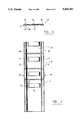
- FIG. 1is an exploded perspective view of a merchandise display rack made in accordance with the invention
- FIG. 2is a rear elevational view of one of the end plates used for the manufacture of the posts of the rack of FIG. 1;
- FIG. 3is a top plan view of the end plate shown in FIG. 2;
- FIG. 4is a side elevational view of one of the side plates used for the manufacture of the posts of the rack of FIG. 1;
- FIG. 5is a top plan view of the side plate shown in FIG. 4;
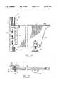
- FIG. 6is a cross-sectional view of one of the posts of the rack shown in FIG. 1;
- FIG. 7is a perspective view of one end of the tie-bar interconnecting the posts of the rack shown in FIG. 1, at the bottom ends thereof;
- FIG. 8is a perspective vide of one end of the tie-bar interconnecting the posts of the rack shown in FIG. 1, at the top ends thereof;
- FIG. 9is a perspective view of one end of the tie-bar interconnecting the posts of the rack shown in FIG. 1, at mid-height thereof;
- FIG. 1is a side elevational view partially broken and in cross-section, of one of the half-bases connected to the bottom end of a post to keep it vertical;
- FIG. 11is a top plan view partially in cross-section and partially broken of the half-base and post assembly show in FIG. 10.
- the merchandise display rack 1as shown in FIG. 1 of the drawings is of a rather conventional structure. It basically comprises two or more vertical posts 3, each having a top end 5, a bottom end 7 and a pair of front and rear surfaces 9, 11 formed with a plurality of vertically aligned apertures for use to detachably secure merchandise shelves 13 through angular brackets 15 in an overhanging fashion.
- the rack 1also comprises at least two and preferably more horizontal tie-bars 17, 19, 21 for rigidly interconnecting each group of two posts adjacent each other in spaced-apart relationship.
- the rack 1further comprises at least one half-base 23 per each post, each having a vertical inner edge 25 from which hooks 27 project and a vertical outer edge 29.
- the half-bases 27are rigidly connectable by means of their hooks 27 to the front or rear surfaces 9, 11 of each post adjacent the bottom end 7 thereof, so as to define a transversal footing sized and positioned to hold the corresponding post 3 vertical even when shelves 13 are secured thereto and loaded with merchandises to be displayed.
- the rack 1may further comprise a kick plate 31 detachably connectable usually by means of hooks to the outer vertical edges 29 of two half-bases 23 that project away in the same direction from two posts 3 adjacent each other, and a bottom shelf 33 also detachably connectable to the same two half-bases 23 in such a manner as to bear on top of the same and of the kick plate connected thereto and extend across the rack.
- a kick plate 31detachably connectable usually by means of hooks to the outer vertical edges 29 of two half-bases 23 that project away in the same direction from two posts 3 adjacent each other
- a bottom shelf 33also detachably connectable to the same two half-bases 23 in such a manner as to bear on top of the same and of the kick plate connected thereto and extend across the rack.
- the rack 1may also comprise wooden panels 35 fixed to its posts 3 and tie-bars to "fill" the frame defined by these structural members whenever desired.
- the inventionin its broadest aspect, essentially lies in the way the posts are made from only two structural pieces easy to manufacture and assemble.
- each of vertical posts 3 used in the rack 1consists of a structural member made of two identical, longitudinally extending end plates 37 that are W-shaped in cross-section and oriented in such a manner as to face each other and define the front and rear surfaces of the post, and of two identical, longitudinally extending side plates that are welded to the end plates 37 to join the same and form the required member which is then of generally rectangular shape.
- each of the end plates 37is advantageously made of one piece of heavy duty material, such as steel.
- This W-shaped piecethat is preferably manufactured by cold forming, comprises:
- a first side wall portion 41which, in use, is positioned so as to project towards the other end plate (see FIG. 6);
- a second side wall portion 43which extends parallel to the first side wall portion and which, in use, is also positioned so as to project towards the other end plate;
- first and second end wall portions 45, 47integrally projecting at 90° from the first and second side wall portions 41, 43, respectively, these first and second end wall portions 45, 47 extending flat in a same plane and projecting towards each other;
- first and second side wall portions 41, 43are flat and sized to bear against and be welded to the side plates 39.
- the first and second end wall portions 45, 47are also flat and each provided with a row of longitudinally oriented slots 53 of a given size.
- the slots 53 of each of the first and second end wall portions 45, 47are transversally aligned over the length of the end plate 37 and form the plurality of vertically aligned apertures mentioned hereinabove, for use to secure light merchandise shelves 13.
- the bottom end wall 51 of the bridging portion 41is also flat and provided with a third row of longitudinally oriented slots 55 of another given size, into which the hooks 25 of the half-base 23 or of a heavier shelf may rigidly be connected.
- each end plate 37may be about 1.125 inches wide and may have a bridging portion 49 that is about 0.313 inch wide and 0.375 inch deep.
- Each end platemay also be formed from a sheet of heavy duty steel in such a manner that its first and second side wall portions 41, 43 as well as its U-shaped bridging portion 49 are about 0.076 thick whereas its first and second end wall portions 5, 47 whose slots 53 are intended to receive and support the lighter shelves, are about 0.062 inch thick.
- the slots 53may be 9/16" ⁇ 5/32" large and spaced apart at a distance of, say, 7/16"
- the slots 55may be 11/16" ⁇ 1/4" large and spaced apart at a distance of, say, 15/16".
- each of side plates 39is made of one piece of light duty material, such as light steel.
- This piecewhich is also preferably manufactured by cold forming, comprises a central portion 61 that is large and flat and a pair of identical side portions 63, 65 edging the central portion.
- Each of the side portions 63, 65has a U-shaped cross-section with a flat bottom 67 extending in the same plane as the central portion, and a pair of inner and outer arms 69, 71 integrally projecting at 90° from the flat bottom 67 in a direction opposite the adjacent end plate 37 (see FIG. 6).
- the inner arm 69is folded back and joins the central portion 61 to form a unitary piece.
- the U-shaped side portions 63, 65 of the side plate 39substantially reinforce the same and give structural rigidity and strength to it.
- each side plate 39may be about 3.75 inches long and have side portions 63, 65 that are about 0.313 inch long and 0.437 inch deep.
- the thickness of the central portion 61may be about 0.125 inch thick.
- each of the side plates 39also comprises attaching means 73 fixed at different heights along the central portion 71 to receive and attach the tie-bars 17, 19, 21.
- These attaching means 73preferably consist of small rectangular plates of light duty material such as light steel, extending transversally to the central portion 61, each small plate having a pair of opposite edges 75, 77 bent at angle and fixed to the central portion 61 by welding, and a main surface 79 extending parallel to the central portion 61 at a short distance away from the same to define a flat hole 81 in which the end of a tie-bar may be attached by hooking.
- all the tie-bars 17, 19, 21 used to interconnect the posts 3are advantageously made from the same pieces of light steel as the side plates 39.
- the horizontal tie-bars 17, 21 used for interconnecting the top and bottom ends 5, 7 of posts 3are of the very same structure and width as the side-plates 39 except that they have ends 83, 85 where the corresponding pair of side portions 63, 65 edging the central portion 61 are cut out and the remaining central portion 61' is bent at 90° and reinforced by longitudinal ribs 87 punched therein.
- the central portions 61' bent at 90°act as hooks and are engageable into the flat holes 81 defined attaching means 73.
- the upper tie-bar 17has its central portions 61' at both of its ends bent at 90° in the same direction as the inner and outer arms 69, 71 of its side portions 63, 65.
- the lower tie-bar 21has its central portions 61' at both of its ends bent at 90° in a direction opposite the inner and outer arms 69, 71 of its side portions 63, 65.
- the purpose of this particular orientationis to allow the side portions 63, 65 of the upper and lower tie-bars 17, 21 to engage the corresponding edges of the wood panel(s) 35 simultaneously with the side portions 63, 65 of the side plates 39 (see FIG. 6).
- the wooden panels 35may be slidably fixed between the inner and outer arms 69, 71 of the side portions of the side plates 39 of the posts 3, and simultaneously between the inner and outer arms 69, 71 of the side portions of the upper ad lower tie-bars on one or both sides thereof, to "close” the rack 1 centrally, as all of these structural elements are made from the same piece and have the same width.
- the intermediary tie-bar(s) 19must of course be smaller in width to extend between the wooden panels 35.
- the tie-bar 19, as is better shown in FIG. 9,may be of the very same structure as the side plates 39, except that both of the side portions edging its central portion 61 are cut out over all of its length and the end 61' of the remaining central portion is bent at 90° and reinforced by longitudinal ribs punched 87 therein.
- the central portions 61' bent at 90°act as hooks and are engageable into the flat hole 81 of the attaching means 73.
- each half-base 23is intended to be rigidly connected to a corresponding post 3 by longitudinal insertion of its hooks 27 into the slots 55 made in the bottom 51 of the bridging portion of the corresponding end plate 37, which, as aforesaid, is structurally very strong, and then by vertical sliding of the half-base down to ensure that its hooks 27 are fully engaged.
- the half-base 23may be provided with a locking pin 91 slidably mounted onto it adjacent the inner edge 25 thereof above one of the hooks 27.
- the locking pin 91is movable into locking position inside the slot 55 of the corresponding post 3 in which the one hook 27 under the locking pin is inserted after the half-base 23 has been connected to the post 3, as is shown in FIG. 10, in order to prevent this half-base from moving up and out of the slots 55 and inadvertently sliding out of the post.
- Each half-base 23may also be provided with vertically extending, L-shaped bearing members 93 on both of its sides adjacent its inner edge 25, which comes into contact with the first and second end wall portions 45, 47 of the end plate 37 of the post 3, and helps in holding the half-base 23 in line with the post (see FIG. 11).
- Each half-base 23 and optionally each post 3may further be provided with height-adjustable levelers 95 comprising bolts fixed to the bottom end of each post 3 and adjacent the outer edge 29 of each half-base 23, to make each transversal footing adjustable.
Landscapes
- Assembled Shelves (AREA)
- Display Racks (AREA)
Abstract
Description
Claims (14)
Priority Applications (2)
| Application Number | Priority Date | Filing Date | Title |
|---|---|---|---|
| US08/096,960US5415301A (en) | 1993-07-26 | 1993-07-26 | Structural post member for merchandise display rack |
| CA002108083ACA2108083C (en) | 1993-07-26 | 1993-10-08 | Structural post member for merchandise display rock |
Applications Claiming Priority (1)
| Application Number | Priority Date | Filing Date | Title |
|---|---|---|---|
| US08/096,960US5415301A (en) | 1993-07-26 | 1993-07-26 | Structural post member for merchandise display rack |
Publications (1)
| Publication Number | Publication Date |
|---|---|
| US5415301Atrue US5415301A (en) | 1995-05-16 |
Family
ID=22259960
Family Applications (1)
| Application Number | Title | Priority Date | Filing Date |
|---|---|---|---|
| US08/096,960Expired - Fee RelatedUS5415301A (en) | 1993-07-26 | 1993-07-26 | Structural post member for merchandise display rack |
Country Status (2)
| Country | Link |
|---|---|
| US (1) | US5415301A (en) |
| CA (1) | CA2108083C (en) |
Cited By (27)
| Publication number | Priority date | Publication date | Assignee | Title |
|---|---|---|---|---|
| FR2741791A1 (en)* | 1995-12-04 | 1997-06-06 | Alser | Frame uprights for storing and displaying merchandise |
| US5664380A (en)* | 1995-07-12 | 1997-09-09 | Hsueh; Jen Shiung | Partition frame structure |
| WO2000047089A1 (en)* | 1999-02-01 | 2000-08-17 | Hl Display Ab | Mounting device for panels |
| US6336298B1 (en)* | 2000-01-28 | 2002-01-08 | Arthur Chou | Partition composition |
| WO2003059121A1 (en)* | 2002-01-17 | 2003-07-24 | Mep S.P.A. | Modular shelves |
| US20030160009A1 (en)* | 2001-11-01 | 2003-08-28 | Wells Andrew D. | Method and apparatus for retail display of cabinets, countertops and related items |
| US6929133B1 (en)* | 2000-01-10 | 2005-08-16 | Mechtronics Corporation | Display system and methods |
| US20070062898A1 (en)* | 2003-04-14 | 2007-03-22 | Teknoa Industrial Inc. | Prefabricating rack frame |
| US20110168651A1 (en)* | 2010-01-13 | 2011-07-14 | Demco, Inc. | Shelving System and Components Thereof |
| NL2006242C2 (en)* | 2011-02-17 | 2012-08-20 | G H Roelofs Holding B V | COMPOSITION FOR THE FLEXIBLE AND REMOVABLE FORM OF A FURNITURE, FIRST COUPLING ELEMENT AND SUPPORT AS PART OF THE COMPOSITION. |
| US20130220947A1 (en)* | 2012-02-23 | 2013-08-29 | Mladen Pintur | Panel for exhibiting items, with changeable elements |
| US20140027397A1 (en)* | 2012-07-30 | 2014-01-30 | Target Brands, Inc. | Assembly for a storage unit |
| JP2016077306A (en)* | 2014-10-09 | 2016-05-16 | 株式会社岡村製作所 | Product display fixtures |
| USD769656S1 (en)* | 2014-07-25 | 2016-10-25 | Accu-Industrie-Bedarf Kunstmann Gmbh | Rack system |
| US20170127832A1 (en)* | 2015-07-20 | 2017-05-11 | Ryan Joseph Klacking | Protective device for fixtures |
| EP3345512A1 (en)* | 2017-01-04 | 2018-07-11 | Mills Display Limited | A shelving post and an adjustable shelving system |
| US20180279782A1 (en)* | 2017-03-28 | 2018-10-04 | Edsal Manufacturing Company, Inc. | Shelving unit with capacity increasing tie members |
| US10413056B2 (en)* | 2017-04-28 | 2019-09-17 | Mills Display Limited | Shelving post and an adjustable shelving system |
| US10448755B1 (en)* | 2018-07-09 | 2019-10-22 | Target Brands, Inc. | Inline display focal |
| US20190387875A1 (en)* | 2018-06-22 | 2019-12-26 | Product Miniature, Inc, d/b/a Plastics | Modular Shelf System |
| US10736415B1 (en)* | 2019-07-22 | 2020-08-11 | Frazier Industrial Company | Formed support member with tab securing feature |
| US10745198B1 (en)* | 2019-07-22 | 2020-08-18 | Frazier Industrial Company | Formed support member with antirotation feature |
| US11068873B1 (en)* | 2020-01-23 | 2021-07-20 | Krish Bala Karthik | Methods, systems, apparatuses, and devices for facilitating advertising of a product |
| USD940545S1 (en)* | 2020-06-22 | 2022-01-11 | Adroit Worldwide Media, Inc. | Front mount arm for gondola |
| US11517128B1 (en)* | 2021-12-23 | 2022-12-06 | Aimee Nieto | System and method for a grazing wall for food and beverages |
| US20230200567A1 (en)* | 2021-12-23 | 2023-06-29 | Aimee Nieto | System and method for a grazing wall |
| AU2018200027B2 (en)* | 2017-01-04 | 2024-09-05 | Mills Display Limited | A shelving post and adjustable shelving system |
Citations (14)
| Publication number | Priority date | Publication date | Assignee | Title |
|---|---|---|---|---|
| US2933196A (en)* | 1957-12-31 | 1960-04-19 | Childs Equipment Company | Base for shelving support |
| US3101681A (en)* | 1961-02-17 | 1963-08-27 | Streater Ind Inc | Shelving assembly |
| US3102641A (en)* | 1961-12-04 | 1963-09-03 | Speedrack Inc | Storage rack |
| US3199471A (en)* | 1963-04-30 | 1965-08-10 | Brev Crea | Collapsible shelvings |
| US3265217A (en)* | 1964-07-22 | 1966-08-09 | Angeles Metal Trim Co | Building construction |
| US3312032A (en)* | 1963-07-05 | 1967-04-04 | Ames Taping Tool Systems Mfg C | Metal stud and panel |
| US3465895A (en)* | 1966-09-20 | 1969-09-09 | Hyman Miller | Storage rack |
| US3570798A (en)* | 1967-10-27 | 1971-03-16 | Savage & Parsons Ltd | Supporting structures for shelves, rails and like members |
| US3587867A (en)* | 1969-07-18 | 1971-06-28 | Streater Ind Inc | Base nose hook lock for display stands |
| US3602159A (en)* | 1969-08-18 | 1971-08-31 | Howard J Marschak | Display rack |
| US3640389A (en)* | 1969-05-12 | 1972-02-08 | Chicago Display Co | Display stand and expendable shelf for use thereon |
| US3672515A (en)* | 1969-12-15 | 1972-06-27 | Pierre Rous | Pallet storage sectional frame structures |
| US4064996A (en)* | 1975-12-17 | 1977-12-27 | Robert L. Shillum | Rack system |
| US4067445A (en)* | 1975-11-19 | 1978-01-10 | Finimetal-Efel, Societe Anonyme | Assembling device between uprights and cross-members for setting up metal structures |
- 1993
- 1993-07-26USUS08/096,960patent/US5415301A/ennot_activeExpired - Fee Related
- 1993-10-08CACA002108083Apatent/CA2108083C/ennot_activeExpired - Fee Related
Patent Citations (14)
| Publication number | Priority date | Publication date | Assignee | Title |
|---|---|---|---|---|
| US2933196A (en)* | 1957-12-31 | 1960-04-19 | Childs Equipment Company | Base for shelving support |
| US3101681A (en)* | 1961-02-17 | 1963-08-27 | Streater Ind Inc | Shelving assembly |
| US3102641A (en)* | 1961-12-04 | 1963-09-03 | Speedrack Inc | Storage rack |
| US3199471A (en)* | 1963-04-30 | 1965-08-10 | Brev Crea | Collapsible shelvings |
| US3312032A (en)* | 1963-07-05 | 1967-04-04 | Ames Taping Tool Systems Mfg C | Metal stud and panel |
| US3265217A (en)* | 1964-07-22 | 1966-08-09 | Angeles Metal Trim Co | Building construction |
| US3465895A (en)* | 1966-09-20 | 1969-09-09 | Hyman Miller | Storage rack |
| US3570798A (en)* | 1967-10-27 | 1971-03-16 | Savage & Parsons Ltd | Supporting structures for shelves, rails and like members |
| US3640389A (en)* | 1969-05-12 | 1972-02-08 | Chicago Display Co | Display stand and expendable shelf for use thereon |
| US3587867A (en)* | 1969-07-18 | 1971-06-28 | Streater Ind Inc | Base nose hook lock for display stands |
| US3602159A (en)* | 1969-08-18 | 1971-08-31 | Howard J Marschak | Display rack |
| US3672515A (en)* | 1969-12-15 | 1972-06-27 | Pierre Rous | Pallet storage sectional frame structures |
| US4067445A (en)* | 1975-11-19 | 1978-01-10 | Finimetal-Efel, Societe Anonyme | Assembling device between uprights and cross-members for setting up metal structures |
| US4064996A (en)* | 1975-12-17 | 1977-12-27 | Robert L. Shillum | Rack system |
Cited By (39)
| Publication number | Priority date | Publication date | Assignee | Title |
|---|---|---|---|---|
| US5664380A (en)* | 1995-07-12 | 1997-09-09 | Hsueh; Jen Shiung | Partition frame structure |
| FR2741791A1 (en)* | 1995-12-04 | 1997-06-06 | Alser | Frame uprights for storing and displaying merchandise |
| WO2000047089A1 (en)* | 1999-02-01 | 2000-08-17 | Hl Display Ab | Mounting device for panels |
| US6929133B1 (en)* | 2000-01-10 | 2005-08-16 | Mechtronics Corporation | Display system and methods |
| US6336298B1 (en)* | 2000-01-28 | 2002-01-08 | Arthur Chou | Partition composition |
| US20030160009A1 (en)* | 2001-11-01 | 2003-08-28 | Wells Andrew D. | Method and apparatus for retail display of cabinets, countertops and related items |
| US7163109B2 (en)* | 2001-11-01 | 2007-01-16 | Masterbrand Cabinets, Inc. | Method and apparatus for retail display of cabinets, countertops and related items |
| WO2003059121A1 (en)* | 2002-01-17 | 2003-07-24 | Mep S.P.A. | Modular shelves |
| US20070062898A1 (en)* | 2003-04-14 | 2007-03-22 | Teknoa Industrial Inc. | Prefabricating rack frame |
| US20110168651A1 (en)* | 2010-01-13 | 2011-07-14 | Demco, Inc. | Shelving System and Components Thereof |
| NL2006242C2 (en)* | 2011-02-17 | 2012-08-20 | G H Roelofs Holding B V | COMPOSITION FOR THE FLEXIBLE AND REMOVABLE FORM OF A FURNITURE, FIRST COUPLING ELEMENT AND SUPPORT AS PART OF THE COMPOSITION. |
| US20130220947A1 (en)* | 2012-02-23 | 2013-08-29 | Mladen Pintur | Panel for exhibiting items, with changeable elements |
| US8967402B2 (en)* | 2012-02-23 | 2015-03-03 | Mladen Pintur | Panel for exhibiting items, with changeable elements |
| US20140027397A1 (en)* | 2012-07-30 | 2014-01-30 | Target Brands, Inc. | Assembly for a storage unit |
| US8967576B2 (en)* | 2012-07-30 | 2015-03-03 | Target Brands, Inc. | Assembly for a storage unit |
| USD769656S1 (en)* | 2014-07-25 | 2016-10-25 | Accu-Industrie-Bedarf Kunstmann Gmbh | Rack system |
| JP2016077306A (en)* | 2014-10-09 | 2016-05-16 | 株式会社岡村製作所 | Product display fixtures |
| US20170127832A1 (en)* | 2015-07-20 | 2017-05-11 | Ryan Joseph Klacking | Protective device for fixtures |
| US11426000B2 (en)* | 2015-07-20 | 2022-08-30 | Ryan Joseph Klacking | Protective device for fixtures |
| EP3345512A1 (en)* | 2017-01-04 | 2018-07-11 | Mills Display Limited | A shelving post and an adjustable shelving system |
| AU2018200027B2 (en)* | 2017-01-04 | 2024-09-05 | Mills Display Limited | A shelving post and adjustable shelving system |
| US20180279782A1 (en)* | 2017-03-28 | 2018-10-04 | Edsal Manufacturing Company, Inc. | Shelving unit with capacity increasing tie members |
| US10299594B2 (en)* | 2017-03-28 | 2019-05-28 | Edsal Manufacturing Company, Inc. | Shelving unit with capacity increasing tie members |
| US10413056B2 (en)* | 2017-04-28 | 2019-09-17 | Mills Display Limited | Shelving post and an adjustable shelving system |
| US10681977B2 (en)* | 2017-04-28 | 2020-06-16 | Mills Display Limited | Shelving post and an adjustable shelving system |
| US10952534B2 (en) | 2018-06-22 | 2021-03-23 | Product Miniature, Inc. | Low voltage modular shelf system |
| US20190387875A1 (en)* | 2018-06-22 | 2019-12-26 | Product Miniature, Inc, d/b/a Plastics | Modular Shelf System |
| US10939756B2 (en)* | 2018-06-22 | 2021-03-09 | Product Miniature, Inc. | Modular shelf system |
| CN112969385A (en)* | 2018-06-22 | 2021-06-15 | 产品微型股份有限公司 | Modular shelving system |
| US10448755B1 (en)* | 2018-07-09 | 2019-10-22 | Target Brands, Inc. | Inline display focal |
| US10945521B2 (en)* | 2019-07-22 | 2021-03-16 | Frazier Industrial Company | Formed support member |
| US10947040B2 (en)* | 2019-07-22 | 2021-03-16 | Frazier Industrial Company | Formed support member |
| US10745198B1 (en)* | 2019-07-22 | 2020-08-18 | Frazier Industrial Company | Formed support member with antirotation feature |
| US10736415B1 (en)* | 2019-07-22 | 2020-08-11 | Frazier Industrial Company | Formed support member with tab securing feature |
| US11068873B1 (en)* | 2020-01-23 | 2021-07-20 | Krish Bala Karthik | Methods, systems, apparatuses, and devices for facilitating advertising of a product |
| US20210233053A1 (en)* | 2020-01-23 | 2021-07-29 | Krish Bala Karthik | Methods, systems, apparatuses, and devices for facilitating advertising of a product |
| USD940545S1 (en)* | 2020-06-22 | 2022-01-11 | Adroit Worldwide Media, Inc. | Front mount arm for gondola |
| US11517128B1 (en)* | 2021-12-23 | 2022-12-06 | Aimee Nieto | System and method for a grazing wall for food and beverages |
| US20230200567A1 (en)* | 2021-12-23 | 2023-06-29 | Aimee Nieto | System and method for a grazing wall |
Also Published As
| Publication number | Publication date |
|---|---|
| CA2108083A1 (en) | 1995-01-27 |
| CA2108083C (en) | 1999-08-03 |
Similar Documents
| Publication | Publication Date | Title |
|---|---|---|
| US5415301A (en) | Structural post member for merchandise display rack | |
| US5433327A (en) | Merchandise display rack with reinforced bases | |
| US3465895A (en) | Storage rack | |
| US4078664A (en) | Cross bar | |
| US9386855B2 (en) | Storage rack and cross-bar support | |
| US3278043A (en) | Storage rack | |
| US20070023376A1 (en) | Modular shelving system | |
| US5012938A (en) | Storage rack corner post | |
| US4607753A (en) | Slotted wall merchandise display panel | |
| US4558647A (en) | Modular shelving | |
| CA1085778A (en) | Shelving structure | |
| US3913498A (en) | Cantilever rack | |
| US4142638A (en) | Prefabricated storage shelves | |
| US3346124A (en) | Modular knockdown shelving construction | |
| US3237779A (en) | Supporting frame | |
| US4013022A (en) | Shelving apparatus | |
| JP5147153B2 (en) | Assembly shelf | |
| US3269338A (en) | Boltless clip | |
| US4467729A (en) | Wide span shelving | |
| US3465898A (en) | Connections for tiered storage rack units | |
| US4287994A (en) | Wedgable storage rack | |
| US3268089A (en) | Deck section for storage rack | |
| US3929248A (en) | Divider and partition device for wire | |
| RU51466U1 (en) | RACK (OPTIONS) | |
| US4098197A (en) | Composite shelving system |
Legal Events
| Date | Code | Title | Description |
|---|---|---|---|
| AS | Assignment | Owner name:KNAPE & VOGT CANADA INC., CANADA Free format text:ASSIGNMENT OF ASSIGNORS INTEREST;ASSIGNORS:BRUTON, JOHN;SALIS, JULIAN DE;REEL/FRAME:006644/0573 Effective date:19930713 | |
| AS | Assignment | Owner name:L.A. DARLING LIMITED, CANADA Free format text:ASSIGNMENT OF ASSIGNORS INTEREST;ASSIGNOR:KNAPE & VOGT CANADA, INC.;REEL/FRAME:009306/0941 Effective date:19980327 Owner name:KNAPE & VOGT CANADA INC./KNAPE & VOGT DU CANADA IN Free format text:CHANGE OF NAME;ASSIGNOR:KNAPE & VOGT MONTREAL INC.;REEL/FRAME:009306/0934 Effective date:19910627 Owner name:KNAPE & VOGT CANADA INC. & KNAPE & VOGT MONTREAL I Free format text:MERGER;ASSIGNOR:ROLL-IT INC.;REEL/FRAME:009289/0171 Effective date:19900629 Owner name:KNAPE & VOGT CANADA INC., CANADA Free format text:MERGER;ASSIGNOR:HIRSH COMPANY CANADA LTD., THE;REEL/FRAME:009297/0650 Effective date:19940502 | |
| FPAY | Fee payment | Year of fee payment:4 | |
| REMI | Maintenance fee reminder mailed | ||
| LAPS | Lapse for failure to pay maintenance fees | ||
| STCH | Information on status: patent discontinuation | Free format text:PATENT EXPIRED DUE TO NONPAYMENT OF MAINTENANCE FEES UNDER 37 CFR 1.362 | |
| FP | Lapsed due to failure to pay maintenance fee | Effective date:20030516 |