US5414591A - Magnetic disk storage system - Google Patents
Magnetic disk storage systemDownload PDFInfo
- Publication number
- US5414591A US5414591AUS07/868,421US86842192AUS5414591AUS 5414591 AUS5414591 AUS 5414591AUS 86842192 AUS86842192 AUS 86842192AUS 5414591 AUS5414591 AUS 5414591A
- Authority
- US
- United States
- Prior art keywords
- magnetic disk
- disk drives
- cooling air
- storage system
- magnetic
- Prior art date
- Legal status (The legal status is an assumption and is not a legal conclusion. Google has not performed a legal analysis and makes no representation as to the accuracy of the status listed.)
- Expired - Lifetime
Links
Images


Classifications
- H—ELECTRICITY
- H05—ELECTRIC TECHNIQUES NOT OTHERWISE PROVIDED FOR
- H05K—PRINTED CIRCUITS; CASINGS OR CONSTRUCTIONAL DETAILS OF ELECTRIC APPARATUS; MANUFACTURE OF ASSEMBLAGES OF ELECTRICAL COMPONENTS
- H05K7/00—Constructional details common to different types of electric apparatus
- H05K7/20—Modifications to facilitate cooling, ventilating, or heating
- H05K7/20709—Modifications to facilitate cooling, ventilating, or heating for server racks or cabinets; for data centers, e.g. 19-inch computer racks
- H05K7/20718—Forced ventilation of a gaseous coolant
- H05K7/20736—Forced ventilation of a gaseous coolant within cabinets for removing heat from server blades
- G—PHYSICS
- G06—COMPUTING OR CALCULATING; COUNTING
- G06F—ELECTRIC DIGITAL DATA PROCESSING
- G06F1/00—Details not covered by groups G06F3/00 - G06F13/00 and G06F21/00
- G06F1/16—Constructional details or arrangements
- G06F1/20—Cooling means
- G—PHYSICS
- G11—INFORMATION STORAGE
- G11B—INFORMATION STORAGE BASED ON RELATIVE MOVEMENT BETWEEN RECORD CARRIER AND TRANSDUCER
- G11B33/00—Constructional parts, details or accessories not provided for in the other groups of this subclass
- G11B33/14—Reducing influence of physical parameters, e.g. temperature change, moisture, dust
- G11B33/1406—Reducing the influence of the temperature
- G11B33/1413—Reducing the influence of the temperature by fluid cooling
- G11B33/142—Reducing the influence of the temperature by fluid cooling by air cooling
Definitions
- the present inventionrelates to a casing structure of a magnetic disk storage system and, more particularly, to a casing structure of a magnetic disk storage system in which a plurality of magnetic disk drives, sometimes called head disk assemblies, are provided, which casing structure can reduce a temperature rise and can suppress a temperature rise to the minimum even if blast means such as cooling fans are out of order.
- the conventional technique disclosed in Japanese Patent Unexamined Publication No. 62-239394includes highly effective cooling means.
- the blast means for the magnetic disk drivesare separate and independent from one another, and consequently, if one of the blast means is out of order or stopped, the temperature of the magnetic disk drive whose blast means cease is raised.
- the piled magnetic disk drivesare cooled successively from the bottom to the top. Therefore, the temperature of cooling air is raised at the downstream side of the flow due to heat exchange with heat generated from the magnetic disk drives. As a result, the higher that the magnetic disk drives are located, the higher the temperatures thereof become.
- Another object of the inventionis to provide a structure which facilitates maintenance and exchange of the magnetic disk drives by minimum units (one by one).
- a further objectis to realize the reduction of thermal off-track which is an essential factor in preventing decreases in durations of component parts and improving the positioning accuracy.
- the inventionprovides a magnetic disk storage system comprising a plurality of magnetic disk drives provided in a system casing, each of the magnetic disk drives including magnetic disks for storing information, magnetic heads for reading and writing information between the magnetic disks, a carriage mechanism for positioning the magnetic heads, and a housing for hermetically sealing them, the magnetic disk storage system further comprising partitions for separating and arranging the magnetic disk drives which are provided between the magnetic disk drives so as to form container chambers of the magnetic disk drives, and blast means for cooling the magnetic disk drives which are provided in the container chambers, the partitions being formed with openings through which cooling air is passed between adjacent two of the container chambers.
- the housingsurrounds each magnetic disk drive so as to prevent foreign materials from sticking to the heads and disk surfaces.
- a plurality of such integral magnetic disk drivesare installed in the casing.
- the magnetic disk drivesare separated individually by the partitions for the sake of convenience of the maintenance and inspection.
- Each of the chambers containing the magnetic disk drivesis provided with the blast means, such as a fan, for cooling the respective magnetic disk drive, and vent holes through which the air is supplied to and discharged from the blast means. With this arrangement, the magnetic disk drives can be effectively cooled.
- openingsare further formed in the partitions defining the chambers in addition to the vent holes.
- a flow resistancesuch as a filter is provided at the upstream or downstream side of flows from the fans, and consequently, back flows of the cooling air can be prevented to thereby supply sufficient cooling air to each of the disk drives.
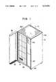
- FIG. 1is a perspective view showing one embodiment of a magnetic disk storage system according to the present invention
- FIG. 2is a side sectional view of the magnetic disk storage system shown in FIG. 1;
- FIG. 3is a side sectional view of another embodiment of magnetic disk storage system shown in FIG. 1;
- FIG. 4is a sectional view showing another embodiment of a magnetic disk storage system according to the invention.
- FIG. 5is a sectional view showing a still other embodiment of a magnetic disk storage system according to the invention.
- FIG. 6is a sectional view taken along the line IV--IV of FIG. 5;
- FIG. 7is a sectional view showing a different embodiment of a magnetic disk storage system according to the invention.
- FIG. 8is a front sectional view partially showing a state in which magnetic disk units are provided in a system casing
- FIG. 9is a perspective view of a magnetic disk unit with a frame structure in place of a partition
- FIG. 10is a perspective view of a magnetic disk unit with a partition
- FIG. 11is a front sectional view showing a state in which magnetic disk units shown in FIG. 10 are provided in the system casing;
- FIG. 12is a longitudinal sectional view of a magnetic disk drive
- FIG. 13is a vertical sectional view of the magnetic disk drive
- FIG. 14is an explanatory view of a magnetic disk drive including radiation fins
- FIG. 15is a perspective view of a magnetic disk drive including radiation fins
- FIG. 16is an explanatory view of linear radiation fins
- FIG. 17is an explanatory view of radial radiation fins
- FIG. 18is an explanatory view of pin-like radiation fins
- FIG. 19is a top sectional view illustrative of a method of cooling a power source and circuit boards
- FIG. 20is a top sectional view illustrative of another method of cooling a power source and circuit boards
- FIG. 21is an explanatory view of a fan provided with opening/closing means when they are opened;
- FIG. 22is an explanatory view of the fan provided with the opening/closing means when they are closed;
- FIG. 23is a side sectional view showing a state in which magnetic disk units are inclined and provided in a system casing
- FIG. 24is a front sectional view showing a configuration of a rail
- FIG. 25is a front sectional view showing a configuration of another rail
- FIG. 26is a diagram for explaining a control system for informing the user of trouble of a fan
- FIG. 27is an explanatory view of a magnetic disk drive including opening/closing means
- FIG. 28is a diagram showing kinds of detectors and their installation positions
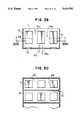
- FIG. 29is a sectional view showing another embodiment of the invention.
- FIG. 30is a sectional view taken along the line XXX--XXX of FIG. 29.
- FIG. 31is a sectional view showing a further embodiment of the invention.
- FIG. 1is a perspective view showing a magnetic disk storage system comprising a plurality of magnetic disk units 31a provided in one casing 9.
- 20 disk units 31aare arrayed in four rows and piled in five layers.
- the magnetic disk storage systemincludes a door 38 for opening and closing the entire surface, an inlet 39 of cooling air which is formed at the bottom of the door 38, an outlet 40 of cooling air, a power source, control circuits and the like 42 for the whole system, and elevating supports or casters 43 of the casing 9.
- reference numeral 41indicates a flow of cooling air.
- the power source, control circuits and the like 42should be cooled not by blower fans 13 attached to the respective disk units but by other fans. In some cases, however, they may be arranged to be cooled by the cooling air 41 which has cooled the disk units 31a.
- Cooling airflows into the system through the door 38 and the cooling air inlet 39 formed at the bottom of the casing 9, moves upwardly, and is distributed to the disk units 31a by the respective blower fans 13. While passing through a duct in each of the disk units 31a, the cooling air cools a magnetic disk drive 1 (which is sometimes called a magnetic disk assembly) and so forth in the unit. Then, the cooling air gathers and moves upwardly in a collecting duct 44, and it is released out of the casing 9 through the outlet 40 at the top of the casing 9.
- a magnetic disk drive 1which is sometimes called a magnetic disk assembly
- FIG. 2is a side sectional view of the casing 9 shown in FIG. 1, illustrative of the above-described cooling method.
- Reference numeral 45denotes a floor on which the casing 9 is mounted.
- additional fansmay be installed in the collecting duct 44 of the cooling air 41 in order to increase an amount of cooling air introduced through the blower fans 13 of the disk units 31a.
- the additional fansshould be installed in the vicinity of the outlet 40 of the collecting duct 44.
- rising air-guide platesmay be provided in those portions of the collecting duct 44 which are adjacent to exits of the cooling air 41 of the respective disk units 31a so as to help the heated cooling air 41 to move upwardly.
- FIG. 3is a side sectional view showing another embodiment of the casing 9.
- the cooling air 41flows into the system horizontally through inlets 39 of downward louver windows 46a on the front surface of the door 38, passes through the ducts in the respective disk units 31a, cools the magnetic disk drives 1 and so forth in the disk units 31a, and then, is released out of the casing 9 horizontally through outlets 40 of upward louver windows 46b.
- the choice between the cooling methods (flow courses of the cooling air 41) illustrated in FIGS. 2 and 3is determined by a location and restricting conditions of the casing 9, these two methods can be combined.
- the airflows into the system horizontally through the inlets 39 of the downward louver windows 46a on the front surface of the door 38, and finally, it gathers and moves upwardly in the collecting duct 44 so as to be released out of the casing 9 through the outlet 40 at the top of the casing 9.
- the inlet 39 formed at the bottom of the door 38 and casing 9may be used in combination with the inlets 39 of the downward louver windows 46a on the side of the door 38.
- FIG. 4is a sectional view showing a portion of a casing of a magnetic disk storage system according to one embodiment of the invention.
- One casing 9contains three magnetic disk drives 1, and partitions 10 for forming ducts are provided between the magnetic disk drives 1.
- Each ductis formed with an inlet 11 and an outlet 12 of cooling air, and a blower fan 13, which is one example of blast means, is provided in the inlet 11.
- a blower fan 13which is one example of blast means
- each partition 10is formed with openings 14 through which cooling air can be passed between two adjacent magnetic disk drives 1.
- each magnetic disk drive 1includes a fan 13, and the openings 14 are formed in the vicinity of those portions of a housing 47 against which cooling air is directly blown from the fan 13.
- the pressure drop in a direction from the opening 14 toward the inlet 11a of the fan 13ais smaller than that in a direction toward the outlet 12a (if the air flow resistance in the direction toward the outlet 12a is larger)
- the part 15a of the air flow 15 which has reached the magnetic disk drive laflows toward the fan 13a.
- the magnetic disk drive 1ais partially exposed to the part 15a of the air flow 15. Consequently, the magnetic disk drive la whose fan 13a is out of order or stopped is cooled by the air flow 15a so as to prevent its temperature from rising abnormally.
- the openings 14are not formed (as in the prior art), there is no way to cool the magnetic disk drive 1a, so that its temperature rise will make it impossible to read data or conduct such operation.
- FIG. 5shows a still other embodiment in which an air filter 16 for removing the dust is provided on the inlet side of the fans 13.
- This air filterserves as one of the resistances of the flows. More specifically, the pressure drop in the direction from the opening 14 toward the inlet 11a becomes larger than that in the direction toward the outlet 12a (the air flow resistance in the direction toward the outlet 12a becomes smaller), and the part 15a of the air flow 15 which has reached the magnetic disk drive la flows along the housing 47 of the magnetic disk drive la toward the outlet 12a.
- the cooling efficiencyis better than that of the embodiment shown in FIG. 4, further suppressing a temperature rise of the magnetic disk drive la whose fan 13a is faulty or ceases operation.
- Reference numeral 29denotes a passage in which the cooling air flows.
- a resistance for regulating the pressure dropair flow resistance
- FIGS. 4 and 5show the embodiments having an arrangement of three magnetic disk drives 1 in one layer.
- FIG. 6illustrates one embodiment comprising magnetic disk drives piled in three layers and arrayed in three rows. This is equivalent to a sectional view taken along the line IV--IV of FIG. 5.
- the number of layers and the number of rowsare not limited to these, and they may be larger.
- vertical and horizontal partitions 10each has an opening 14. For instance, if a fan 13a of a magnetic disk drive 1a indicated by A is stopped, a part 15a of the air flow 15 produced by each of the normally functioning fans 13b of three magnetic disk drives 1b indicated by B which are adjacent to the disk drive 1a flows toward the magnetic disk drive 1a and cools it. Needless to say, openings may be only formed in either vertical or horizontal partitions 10.
- FIG. 7illustrates one embodiment in which the cooling air flows 15 are reversed.
- suction fans 13are provided as blast means.
- the positions of the inlets 11 and the outlets 12are, of course, reverse to those shown in FIG. 4 and so on, the same function and effect as described before can be obtained due to the openings 14 formed in the partitions 10.
- FIG. 7similarly shows a condition in which the fan 13a of the magnetic disk drive 1a is stopped. In this case, a temperature rise of the magnetic disk drive 1a can be suppressed due to the effect of the invention.
- FIG. 8is a front sectional view partially showing magnetic disk units provided in the casing. Partitions 10 for partitioning a plurality of disk units 31b individually are formed, in advance, in the casing 9 regularly and separately from the disk units 31b, and each of the partitions 10 is formed with openings 14 through which cooling air 41 can be passed. Then, the plurality of disk units 31b are installed separately between the partitions 10.
- FIG. 9is a perspective view of each of such disk units 31b which is constituted of a magnetic disk drive 1, a blower fan 13 serving as blast means for the magnetic disk drive 1, and a frame 50 for sustaining them.
- each disk unit 31bonly comprises a magnetic disk drive 1 and a blower fan 13).
- each magnetic disk unitis provided in a duct 2. That is to say, the duct 2 of a disk unit 31a surrounds four peripheral sides of a magnetic disk drive 1 and serves as partitions 10. Other than an inlet 11 and an outlet 12 of cooling air, the duct 2 is formed with openings 14 through which cooling air can be passed between adjacent magnetic disk drives.
- Each of the surfaces of the duct 2(four surfaces corresponding to partition 10 except the surfaces which include the inlet 11 and the outlet 12) includes one opening 14. Needless to say, two or more openings may be formed in each surface, and the openings will not be restricted to a rectangular shape and can have a desired shape such as a circular one.
- one portion of the duct 2 serving as partitions surrounding four sides of the magnetic disk drive 1may be defined by a part of a control circuit board 32 or 52b (see FIG. 19) which will be described later.
- one surface of the duct 2is defined by the control circuit board 32 or 52b, in which an opening 14 is also formed.
- the cooling airflows through a gap (passage 29) between the duct 2 and the magnetic disk drive 1.
- the drive power source and the control circuit board 32 for the magnetic disk drive 1are provided in the disk unit 31a of this embodiment.
- the magnetic disk drive 1may be installed in the disk unit 31a, and the drive power source and the control circuit board 32 may be cooled in substantially the same manner as the power source, the control circuit 42 and so forth for the whole magnetic disk storage system shown in FIG. 1.
- blast meansis a blower fan 13 (a pressurized type axial-flow fan) which blows cooling air against the magnetic disk drive 1, and this blower fan is installed on the side of the inlet 11.
- a single blower fan 13is used for each unit, but several blower fans having a small diameter may be used instead.
- one magnetic disk drive 1, one duct 2, one blower fan 13 serving as blast means for the magnetic disk drive 1, and so forthconstitute each disk unit 31a.
- the temperature of the fan 13can be kept low so as to maintain the fan 13 for a long duration.
- the duration of life of a fanclosely relates to its temperature, and as the temperature is higher, the bearing failure rate of the fan will be increased. Consequently, when the fan 13 is located behind the magnetic disk drive 1, the drive power source and the control circuit board 32 (on the side of the outlet 12), the temperature of the cooling air 41 is raised due to waste heat from these heat sources, and the temperature of the fan 13 is also raised, thereby increasing the bearing failure rate of the fan 13.
- FIG. 11is a front sectional view partially showing one embodiment of the casing 9 for a magnetic disk storage system in which a plurality (eight in the drawing) of the above-described disk units 31a are provided.
- Frames 33 for separating the plurality of disk units 31aare formed in the casing 9.
- Adequate openings 34are formed in the frames 33 so that cooling air can pass through them.
- the frames 33 extending horizontallyare shown in the drawing, vertical frames for reinforcement and so forth may be added.
- rails 35On an upper portion of each horizontal frame 33, there are provided rails 35 long in depth which enable smooth installation of each disk unit 31a. In this case, wheels or the like may be attached to the bottom of the disk unit 31a. By sliding the disk unit 31a on the rails 35, it can be installed in the casing 9.
- the openings 14are formed in the ducts 2 of the four disk units 31a shown in FIG. 10 which are mounted on the horizontal frame 33, it is necessary to align the positions of the openings 14 of the disk units 31a so that the cooling air can be passed between adjacent disk units 31a. It is also necessary to prevent the cooling air from leaking out of the ducts 2 through gaps 36 between adjacent openings 14. Therefore, elastic members may be attached to the peripheries of the openings 14 to thereby bring adjacent openings 14 into favorable contact. Concerning the disk units 31a which are located on ends (in contact with outer frames of the casing 9), it is not necessary to form an opening 14 in the surface of the duct 2 which is adjacent to no disk unit 31a.
- cover platesmay be provided later to cover unnecessary openings 14, or the duct 2 and the outer frames of the casing 9 may be arranged to have no gaps 37 therebetween, or the gaps 37 may be made as narrow as possible, in order to increase the passage resistance of the air flow and to prevent the leakage thereof.
- FIG. 12is a longitudinal sectional view partially showing one embodiment of the disk unit 31a and magnetic disk drive 1 shown in FIG. 10, and FIG. 13 is a vertical sectional view showing an essential portion of the magnetic disk drive 1, taken along the axial line.
- the magnetic disk drive 1is hermetically sealed in a housing 47 to shut out the environmental air. Inside of the housing 47, a plurality of piled magnetic disks 3 for storing information rotate at high speed about a spindle 4.
- Magnetic heads 5 for reading and writing information of the magnetic disks 3are provided on the distal ends of a large number of head arms 6, and the head arms 6 gain access to the magnetic disks 3 at high speed through a carriage mechanism 7 which is actuated by a voice coil motor 8, so that the magnetic heads 5 will be located accurately at predetermined positions on the magnetic disks 3.
- a magnetic disk storage systemhas two types of arrangement for positioning control.
- Oneis a dedicated servo method the system of which includes a large number of data surfaces and an exclusive servo surface on which positioning information is stored, and positioning control is constantly performed on the basis of servo information of the servo surface.
- the otheris an embedded servo method the system of which does not include any exclusive servo surface for positioning information but positioning information is stored on a part of a data surface, and positioning control is performed on the basis of servo information of the data surface.
- the cooling method according to the inventionis effective particularly for a magnetic disk storage system of the dedicated servo method for positioning control for the following reason: In the dedicated servo method, as shown in FIG.
- a single servo head 5aconducts positioning control of a large number of data heads (heads except the head 5a), and consequently, if a temperature rise of the magnetic disk drive 1 or a difference in a temperature distribution of the magnetic disk drive 1 is large, a thermal expansion difference is generated between the magnetic disks 3 or between the head arms 6, thus deteriorating the positioning accuracy.
- the magnetic disk drive 1is not necessarily restricted to the structure shown in FIGS. 12 and 13.
- the magnetic heads 5 and the carriage mechanism 7 of this embodimentare of a linear type for linear movements, they may be of a swing type for arcuate rotations.
- the number of the magnetic disks 3may be either one or plural.
- the diameter of each magnetic disk 3may be as large as 8 to 10 inches or more, and it may be as small as 5.25, 3.5, 2.5, 1.8 inches and so on.
- the magnetic disks 3may be arranged vertically (the spindle is extended horizontally) as shown in FIG. 12, and they may be arranged horizontally (the spindle is extended vertically).
- the above-described openings 14 through which the cooling air 41 can be passedare formed in those portions of the duct 2 which are adjacent to the surfaces of the housing 47 of the magnetic disk drive 1. Under the circumstances, the temperature of the magnetic disk drive 1 is raised owing to a wind loss by rotations of the magnetic disks 3, a loss by resistances of a large number of head arms 6, heat generated in the voice coil motor 8, and so forth, Therefore, cooling of the magnetic disk drive 1 is an indispensable factor for improving the reliability.
- FIGS. 14 to 18show embodiments in which fins are formed on the magnetic disk drive 1 so as to enhance the cooling effect.
- a jet of cooling air 15 having whirling components produced by the blower fan 13is directly blown against a front surface 47c of the housing 47 of the magnetic disk drive 1, and this portion of the magnetic disk drive 1, which is suitable for heat transfer, is provided with a large number of radiation fins 18.
- the portion suitable for heat transferis located on the side of a disk chamber containing the magnetic disks 3, as shown in FIG. 12, remarkably favorable heat transfer is realized inside of the housing 47 because the magnetic disks 3 are rotating at high speed in the disk chamber inside the housing 47.
- Highly favorable heat transferis also realized outside of the housing 47 by jet cooling and the radiation fins 18 described above.
- the overall coefficient of heat transmission(which is an inverse of a thermal resistance) is significantly increased.
- FIG. 15is a perspective view of the magnetic disk drive 1, and as in this example, the radiation fins 18 may be formed of several (five in the drawing) thin plate-like fins. Further, the radiation fins 18 should preferably be made of a material having a high thermal conductivity. In the case where they are integrally formed with the housing 47, an aluminum material (such as an aluminum alloy and an aluminum casting) is suitable. In the above-described embodiment, the radiation fins 18 are formed only on the front surface 47c of the housing 47 of the magnetic disk drive 1 against which the cooling air jet 15 is directly blown.
- radiation fins 18may be formed additionally on all the other surfaces or necessary portions of the housing 47, to thereby improve the cooling efficiency to a further extent. Also, the configuration of these radiation fins 18 may be arranged in such a manner that they also function as reinforcement ribs or the like of both side surfaces (47a, 47b) of the housing 47 which sustain the spindle portion of the magnetic disk drive 1.
- reference numeral 48denotes a motor for driving the magnetic disks 3, and in this embodiment, the motor 48 is directly connected to the tip of one end of the spindle.
- heatis generated in the motor 48 due to its loss, so that a temperature difference will be easily generated between the housing surface 47a on which the motor 48 is provided and the opposite housing surface 47b with no motor.
- favorable heat transfercan be realized by making the area of the radiation fins 18 formed on the housing surface 47a with the motor 48 larger than that on the opposite housing surface 47b with no motor, or alternatively, by making the flow velocity of the cooling air flowing on the housing surface 47a with the motor 48 higher than that on the opposite housing surface 47b with no motor. Also, both the methods may be combined.
- FIGS. 16 to 18show other configurations of fins, as viewed in a direction from the blower fan.
- linear fins 18aare arranged in parallel and provided on the receiving portion 17 of the air flow from the blower fan 13 and in its vicinity.
- the linear fins 18amay be further divided into thinner fins and may be arranged in a zigzag or stagger form.
- linear fins 18bare arranged in a radial form and provided on the air flow receiving portion 17 from the fan 13. The air from the fan 13 flows along the linear fins 18b in the radial form toward the outer periphery.
- the radiation fins 18b in the radial formneed not be linear toward the outer periphery, but they may be curved with a certain curvature in a direction of the air flow blown from the fan 13.
- pin-like fins 18cwhich are provided on the air flow receiving portion 17.
- the pin-like fins 18cperform remarkably favorable heat transfer, it is necessary to arrange them rather densely so as to increase the radiation area.
- extremely thin (1 mm or less) pin-like fins 18care manufactured and arranged densely on the housing 47.
- the cross-sectional shape of the pin-like fins 18cneed not be circular, but it may be oval, rectangular, and so forth.
- projections and uneven portionsmay be manufactured by adhering a foreign material on the duct 2 by an adhesive or the like in the post-treatment after finishing the duct 2, or by blowing sand or the like against the inner walls of the duct 2 by use of the sand blast so as to make them rough, or by forming the projections and uneven portions integrally with the duct 2 in a method of pressing, mechanical machining, or the like.
- the drive power source, the control circuit board 32 and so forthare added to the disk unit 31a, such projections and uneven portions and the like should preferably be formed similarly on inner walls of the duct 2 in the vicinity of them.
- FIGS. 19 and 20show embodiments of cooling methods of the drive power source and the control circuit board 32 in the case where the drive power source and the control circuit board 32 are added, for example, to the respective disk units 31a and 31b shown in FIGS. 9 and 10.
- Reference numerals 52a and 52bdenote an example of a circuit board provided inside a container box of the drive power source and the control circuit board 32 and an example of a circuit board provided outside the container box.
- openings for passing the cooling air 41are formed in a front surface portion 32a and a back surface portion 32b of the container box so that the cooling air 41 which has cooled the magnetic disk drive 1 flows inside the container box.
- the circuit boards 52a and 52b provided inside and outside the container boxare extended neatly along the cooling air flow.
- inlets through which the cooling air 41 is forcibly introduced into the container boxare formed in side-surface front portions 32c of the container box rather than the front surface portion 32a, and outlets are formed in the back surface portion 32b.
- the circuit boards 52a provided inside the container boxmay be arranged in such a manner that front end portions of them are gradually shortened from the center toward the side ends of the container box, as shown in the drawing.
- each of the boards 52acan be effectively cooled by the cooling air 41.
- the drive power source and the control circuit board 32may be exposed like, for example, the circuit board 52b, instead of being provided inside the container box. In these cases, it is, of course, necessary to pay much attention to the insulation and so on.
- FIGS. 21 and 22only illustrate the fan 13 of FIG. 4 and its vicinity, showing one embodiment for forcibly controlling the cooling air flow 15 at the time of stoppage of the fan 13.
- Each of the fans 13is provided with a fan guide 19 and a damper 20 which is provided on the fan guide 19, respectively, so as to function as opening/closing means for controlling the cooling air flow 15.
- FIG. 21shows a condition when the fan 13 is normally rotating, in which damper sections 20a and 20b are pushed open due to a pressure of the air from the fan 13 (open condition).
- FIG. 22shows a condition when the fan 13 is out of order or stopped, in which the damper sections 20a and 20b are closed owing to their resilient forces (closed condition).
- opening/closing meanstake the following effect. For instance, referring to FIG. 4, when each of the fans 13 is normally rotating, the damper 20 is in the open condition, and the cooling air flow 15 from the fan 13 moves from the inlet 11 to the outlet 12 along the housing 47 of the magnetic disk drives 1. In this case, there are no flow interferences between the magnetic disk drives 1. If the fan 13a falls into trouble or ceases operation, the damper 20 of the fan 13a is in the closed condition owing to its resilient force (while the other fans 13 are in the open condition). After a part 15a of the air flow 15 from each of the adjacent fans.
- the damper 20serves as an air flow resistance of the flow similar to the air filter 16 for removing the dust, shown in FIG. 5. Since the resistance of the damper 20 is larger, the effect of it is accordingly larger.
- the damper 20 shown in FIGS. 21 and 22is opened/closed by use of the air pressure generated by the fan 13, there is another method in which on and off states of operation of the fan 13 are detected, and the damper 20 is forcibly opened/closed in response to the detection output. In this case, however, a driving force is required.
- the damper 20 shown in FIGS. 21 and 22is divided into two sections (20a, 20b), it may be divided into three or more.
- the opening/closing meansare not necessarily limited to the damper 20 shown in FIGS. 21 and 22.
- FIG. 23is a side sectional view showing a condition in which the disk units 31 are provided (cooled) in the casing 9 according to one embodiment of the invention.
- each disk unit 31 (31a or 31b) in FIG. 23is inclined in such a manner that its longitudinal direction (the direction of the cooling air flow) extends at an angle ⁇ with respect to the horizontal direction.
- One object of this arrangementis to make the flow of the cooling air 41 smooth. Since the air heated as a result of cooling of the disk unit 31 tends to move upwardly due to a decrease in the density, a rear end portion of the disk unit 31 is lifted up to help the upward movement of the air.
- the inclination angle ⁇must be large to a certain degree, it is restricted by the dimensions of the casing 9 and the disk unit 31, and consequently, even slight inclination can produce some effect. Spaces 53a and 53b generated owing to the inclined arrangement can be used for storing auxiliary members and the like.
- the inclination angle ⁇may have a negative value. The reason is that, with the structure where the cooling air 41 flows in from the back of the casing 9 and flows out from the front, the cooling air 41 flows in each of the disk units 31 from the back to the front, so that it is better to lift the front portion of the disk unit 31. That is to say, the inclination angle ⁇ may have either a positive value or a negative value so far as the inclination is directed not to interfere the flow of the cooling air 41.
- FIG. 24illustrates the sectional configuration of the above-described rail 35 shown in FIGS. 8 and 11, as viewed from the front.
- a portion of the rail 35 in contact with the disk unit 31is circular in cross section.
- the rail 35is made of a single material such as a metal, e.g., an SUS (stainless steel) material, and an ethylene tetrafluoride resin (PTFE) material.
- the portion of the rail 35 in contact with the disk unit 31may be rectangular or trapezoidal in cross section.
- the rail 35may be made of an elastic material such as rubber so that it also functions as a shock mount for absorbing the self oscillation of the disk unit 31 and for shutting out the outside oscillation.
- FIG. 25shows another embodiment of the rail 35 a main body of which is made of an elastic material such as rubber to absorb the oscillation whereas a metal plate such as a thin SUS plate 35a is provided on the surface (the contact portion with the disk unit 31).
- the rail 35not only functions as a shock mount but also helps the disk unit 31 to be smoothly received into the casing.
- the contact portion of the rail 35may be rectangular or trapezoidal in cross section.
- each magnetic disk drive 1cooling of each magnetic disk drive 1 is performed in each disk unit 31 comprising a fan 13 and a duct 2 (or a partition 10) which surrounds the magnetic disk drive 1. Therefore, when the magnetic disk drive 1 is out of order or to be inspected for maintenance, it can be taken out by removing the disk unit 31 as a minimum unit from the casing 9, so that operation of the other disk units 31 (magnetic disk drives 1) can be continued without stopping them. In this case, removal of the disk unit 31 from the casing 9 can be effected, for instance, simply by drawing it to the front (toward the door 38) in FIG. 1.
- blower or suction fans 13are employed as blast means.
- a system like a blower or a compressormay be provided so that compressed air produced by the system is guided through pipes, ducts and the like and distributed to the disk units 31.
- substantially the same effect as the fans 13can be expected.
- the temperature of the above-mentioned cooling air 41 produced by the fans 13 or the blower or compressormay be made lower than that of the air in the environment of the casing 9 by the cooler, and the cooling air 41 thus refrigerated may be supplied to the disk units 31.
- the temperature of the cooling air 41in order to prevent humidity from entering the system, the temperature of the cooling air 41 must be carefully maintained not to be lower than the dew-point temperature.
- cooling air 41 which has finished cooling the magnetic disk drives 1is not released from the casing 9 but collected and supplied, as it is, to the inlet: of the cooler, a closed loop of the cooling air 41 can be realized, thereby further preventing the dust from entering the inside of the casing 9.
- part of the cooling watermay be used as a refrigerant of the cooler, or a refrigerant of a refrigerating cycle with a heat pump and the like which is additionally provided in the magnetic disk storage system may be used as the refrigerant.
- the refrigerating cyclehere comprises a compressor, a condenser, an evaporator (cooler to obtain cold cooling air 41), an expander, a switch valve such as a four-way valve, and pipes and the like for connecting them.
- a fin-tube type heat exchangeris suitable. Heat exchange is conducted by flowing the air for cooling the magnetic disk drives 1 between the surfaces of fins and by flowing the refrigerant in the tube, to thereby obtain cold cooling air 41.
- a heat pipe, a thermo electric cooler (Peltier element), and so forthcan be employed.
- the coolerin order to cause the magnetic disk drives 1 to reach a predetermined temperature rapidly, the cooler may be made to function as a condenser by changing the valve (e.g., a four-way valve) in the refrigerating cycle at the time of the start of the magnetic disk drives 1, so that heated air is generated in the condenser, and that the heated air is supplied into the disk units 31 so as to raise the temperatures of the magnetic disk drives 1 quickly.
- the valveis changed to make the cooler function as the evaporator for the original purpose.
- detection means for detecting operational conditions of the fans 13 (blast means) of the respective disk units 31may be provided additionally in the system casing 9 so as to inform the user of the trouble or stoppage of the blast means 13 with output signals from the detection means when the blast means 13 are out of order or stopped.
- FIG. 26illustrates one embodiment of this arrangement in which each fan 13 is provided with a detector 21 for detecting the operational condition of the fan 13, and its signal line 22 is connected to a control circuit 23.
- the detector 21one for detecting an electric current or power of the fan 13 can be used.
- a detector 21a of the fan 13aWhen a certain fan 13a falls into trouble, the fact is detected by a detector 21a of the fan 13a, and visible or audible signals are produced via an output line 24 from the control circuit 23 so as to inform the user.
- a method for informing the userthere are a method of using an indication lamp, as indicated by reference numeral 25, a method of using a speaker, as indicated by numeral 26, a method of printing, as indicated by numeral 27, and so forth. Although each of these methods may be used individually, they may be combined. Such a control method illustrated in FIG. 26 will take greater effects when it is combined with the other embodiments of the invention.
- FIG. 27illustrates one embodiment in which stoppage detectors are applied to a magnetic disk storage system, only showing the center magnetic disk drive 1a of FIG. 4 and its vicinity. Substantially the same function can be expected from the other magnetic disk drives 1.
- Reference numeral 20c, 20ddenotes opening/closing means similar to the damper shown in FIG. 21, which can be swung about hinges 28. While the fan 13a is normally functioning, the damper means 20 are in the condition 20c (indicated by dashed lines), and a cooling air flow 15 generated by the fan 13a moves toward the outlet 12a.
- the detector 21detects that the fan 13a is faulty, and the damper means 20, which are provided in the openings 14 of the duct-forming partition 10 of the magnetic disk drive 1a with the fan 13a, are displaced into the condition 20d (indicated by solid lines) in response to a command sent through an output line 24a of the control circuit 23, so that a part 15a of the cooling air flow 15 from each of the adjacent magnetic disk drives 1 is introduced into the duct-like passage 29. Further, simultaneously through the other output line 24b of the control circuit 23, the indication lamp 25, the speaker 26 and means for the printing 27 are operated to inform the user, as shown in FIG. 26.
- the damper means 20 shown in FIG. 27 serving as opening/closing meansmay be a sliding type instead of the swinging type.
- FIG. 28shows examples of detection methods for detecting the operational condition of the fan 13.
- the detector 21there can be suggested an ammeter 21a for detecting an electric current from a power source of the fan 13, an anemometer 21b for detecting a flow velocity in a blowing section of the fan 13, a differential manometer 21c for detecting pressures of the air in front of and at the back of the fan 13, and so on. Although each of them may be used individually, they may be combined. Their signal lines 22 are connected to the control circuit 23 so that the above-described control is carried out. Besides, even if the blast means are not the fan 13, such detection means 21 can be employed.
- the following operationcan be performed With the detector 21.
- the useris informed of the trouble of the fan 13 by way of the detector 21, and also, the rotational speeds of cooling fans 13 for disk units 31 adjacent to the disk unit 31 in question are controlled in response to the output of the detector so as to increase the amount of air supply.
- the rotational speeds of cooling fans 13 for disk units 31 adjacent to the disk unit 31 in questionare controlled in response to the output of the detector so as to increase the amount of air supply.
- the rotational speeds of cooling fans 13 for disk units 31 adjacent to the disk unit 31 in questionare controlled in response to the output of the detector so as to increase the amount of air supply.
- FIGS. 29 to 31show still other embodiments of the invention.
- FIGS. 29 and 31are sectional views, as viewed in the same direction as the embodiment of FIG. 4, and FIG. 30 is a sectional view corresponding to FIG. 6.
- the number of magnetic disk drives 1 with no partitions 10may be more than three.
- the air flow produced by the fans 13may be either in a direction 15a (blowing) or in a direction 15b (suction).
- FIG. 30shows an example in which casings 9 according to the embodiment of FIG.
- partitions 10are provided only between the upper and lower layers (there are no partitions 10 between the magnetic disk drives in each layer but only the openings 14 are formed therebetween). Needless to say, the partitions 10 and the openings 14 may be provided in the opposite relation, or there may be provided no partitions 10 in either direction but only the openings 14 may be formed (the casing 9 may include the outer frames alone).
- two magnetic disk drives 1are always treated as a pair, and partitions 10 to form ducts are provided between these pairs whereas there is no partition 10 between the two magnetic disk drives 1 in each pair but only the opening 14 is formed therebetween.
- the number of the magnetic disk drives 1 and the number of fans 13need not be the same. This embodiment produces substantially the same effect as the one shown in FIG. 29.
Landscapes
- Engineering & Computer Science (AREA)
- General Engineering & Computer Science (AREA)
- Physics & Mathematics (AREA)
- Theoretical Computer Science (AREA)
- Computer Hardware Design (AREA)
- Thermal Sciences (AREA)
- Microelectronics & Electronic Packaging (AREA)
- Human Computer Interaction (AREA)
- General Physics & Mathematics (AREA)
- Cooling Or The Like Of Electrical Apparatus (AREA)
Abstract
Description
The present invention relates to a casing structure of a magnetic disk storage system and, more particularly, to a casing structure of a magnetic disk storage system in which a plurality of magnetic disk drives, sometimes called head disk assemblies, are provided, which casing structure can reduce a temperature rise and can suppress a temperature rise to the minimum even if blast means such as cooling fans are out of order.
In a conventional magnetic disk storage system in which a plurality of magnetic disk drives are provided, as disclosed in Japanese Patent Unexamined Publication No. 62-239394, air passages and blast means, independent from one another, are provided surrounding the magnetic disk drives so as to cool the respective magnetic disk drives separately and individually. In another conventional system, as disclosed in Japanese Patent Unexamined Publication No. 2-266599, top and bottom surfaces of a casing of each magnetic disk drive are opened, and a fan is installed to produce a cooling air flow from the bottom toward the top, in order to cool piled magnetic disk drives successively.
As a measure to deal with troubles of blast means, as disclosed in Japanese Patent Unexamined Publication No. 3-97187, there is a method in which two blast means are provided for each magnetic disk drive so that, when one of the blast means falls into trouble, the other will be operated.
The conventional technique disclosed in Japanese Patent Unexamined Publication No. 62-239394 includes highly effective cooling means. However, the blast means for the magnetic disk drives are separate and independent from one another, and consequently, if one of the blast means is out of order or stopped, the temperature of the magnetic disk drive whose blast means cease is raised. In the conventional technique disclosed in Japanese Patent Unexamined Publication No. 2-266599, the piled magnetic disk drives are cooled successively from the bottom to the top. Therefore, the temperature of cooling air is raised at the downstream side of the flow due to heat exchange with heat generated from the magnetic disk drives. As a result, the higher that the magnetic disk drives are located, the higher the temperatures thereof become. Especially in the case of a disk array system in which the number of vertically piled layers is larger, a temperature difference between upper disk drives and lower ones tends to increase. Thus, concerning these two techniques, it is feared that positioning accuracy of disk drives will be degraded to thereby deteriorate the reliability of the magnetic disk storage system.
In the conventional technique disclosed in Japanese Patent Unexamined Publication No. 3-97187, which is a measure to deal with troubles of the blast means, two blast means are provided for each of a plurality of magnetic disk drives. In consequence, the number of the required blast means is twice as large as that of the magnetic disk drives, thereby enlarging the spaces they occupy and increasing their costs. This method involves other problems. For example, it is necessary to provide a control circuit for switching the blast means when one of the blast means falls into trouble.
It is therefore an object of the invention to provide a highly reliable magnetic disk storage system in which magnetic disk drives are cooled effectively so that temperature rises of the magnetic disk drives are equally reduced, and in case that blast means for a certain magnetic disk drive is out of order or stopped, a temperature rise of the magnetic disk drive provided with the blast means which is out of order is suppressed to the minimum. Another object of the invention is to provide a structure which facilitates maintenance and exchange of the magnetic disk drives by minimum units (one by one). A further object is to realize the reduction of thermal off-track which is an essential factor in preventing decreases in durations of component parts and improving the positioning accuracy.
In order to achieve these objects, the invention provides a magnetic disk storage system comprising a plurality of magnetic disk drives provided in a system casing, each of the magnetic disk drives including magnetic disks for storing information, magnetic heads for reading and writing information between the magnetic disks, a carriage mechanism for positioning the magnetic heads, and a housing for hermetically sealing them, the magnetic disk storage system further comprising partitions for separating and arranging the magnetic disk drives which are provided between the magnetic disk drives so as to form container chambers of the magnetic disk drives, and blast means for cooling the magnetic disk drives which are provided in the container chambers, the partitions being formed with openings through which cooling air is passed between adjacent two of the container chambers.
The housing surrounds each magnetic disk drive so as to prevent foreign materials from sticking to the heads and disk surfaces. A plurality of such integral magnetic disk drives are installed in the casing. The magnetic disk drives are separated individually by the partitions for the sake of convenience of the maintenance and inspection. Each of the chambers containing the magnetic disk drives is provided with the blast means, such as a fan, for cooling the respective magnetic disk drive, and vent holes through which the air is supplied to and discharged from the blast means. With this arrangement, the magnetic disk drives can be effectively cooled. In this invention, openings are further formed in the partitions defining the chambers in addition to the vent holes. Thus, even if the fan which is originally intended to supply air flows to a certain magnetic disk drive can not function normally due to some trouble or the like, parts of air flows from fans for adjacent disk drives can be introduced through the above-mentioned openings into the magnetic disk drive whose fan ceases, to thereby cool all the magnetic disk drives. Since cooling air can be blown against any of the magnetic disk drives, temperature rises of the disk drives can be suppressed to the minimum in order to prevent reading/writing trouble and malfunction.
Moreover, a flow resistance such as a filter is provided at the upstream or downstream side of flows from the fans, and consequently, back flows of the cooling air can be prevented to thereby supply sufficient cooling air to each of the disk drives.
FIG. 1 is a perspective view showing one embodiment of a magnetic disk storage system according to the present invention;
FIG. 2 is a side sectional view of the magnetic disk storage system shown in FIG. 1;
FIG. 3 is a side sectional view of another embodiment of magnetic disk storage system shown in FIG. 1;
FIG. 4 is a sectional view showing another embodiment of a magnetic disk storage system according to the invention;
FIG. 5 is a sectional view showing a still other embodiment of a magnetic disk storage system according to the invention;
FIG. 6 is a sectional view taken along the line IV--IV of FIG. 5;
FIG. 7 is a sectional view showing a different embodiment of a magnetic disk storage system according to the invention;
FIG. 8 is a front sectional view partially showing a state in which magnetic disk units are provided in a system casing;
FIG. 9 is a perspective view of a magnetic disk unit with a frame structure in place of a partition;
FIG. 10 is a perspective view of a magnetic disk unit with a partition;
FIG. 11 is a front sectional view showing a state in which magnetic disk units shown in FIG. 10 are provided in the system casing;
FIG. 12 is a longitudinal sectional view of a magnetic disk drive;
FIG. 13 is a vertical sectional view of the magnetic disk drive;
FIG. 14 is an explanatory view of a magnetic disk drive including radiation fins;
FIG. 15 is a perspective view of a magnetic disk drive including radiation fins;
FIG. 16 is an explanatory view of linear radiation fins;
FIG. 17 is an explanatory view of radial radiation fins;
FIG. 18 is an explanatory view of pin-like radiation fins;
FIG. 19 is a top sectional view illustrative of a method of cooling a power source and circuit boards;
FIG. 20 is a top sectional view illustrative of another method of cooling a power source and circuit boards;
FIG. 21 is an explanatory view of a fan provided with opening/closing means when they are opened;
FIG. 22 is an explanatory view of the fan provided with the opening/closing means when they are closed;
FIG. 23 is a side sectional view showing a state in which magnetic disk units are inclined and provided in a system casing;
FIG. 24 is a front sectional view showing a configuration of a rail;
FIG. 25 is a front sectional view showing a configuration of another rail;
FIG. 26 is a diagram for explaining a control system for informing the user of trouble of a fan;
FIG. 27 is an explanatory view of a magnetic disk drive including opening/closing means;
FIG. 28 is a diagram showing kinds of detectors and their installation positions;
FIG. 29 is a sectional view showing another embodiment of the invention;
FIG. 30 is a sectional view taken along the line XXX--XXX of FIG. 29; and
FIG. 31 is a sectional view showing a further embodiment of the invention.
One embodiment of the present invention will be hereinafter described with reference to FIG. 1. FIG. 1 is a perspective view showing a magnetic disk storage system comprising a plurality ofmagnetic disk units 31a provided in onecasing 9.
In this embodiment, 20disk units 31a are arrayed in four rows and piled in five layers. The magnetic disk storage system includes adoor 38 for opening and closing the entire surface, aninlet 39 of cooling air which is formed at the bottom of thedoor 38, anoutlet 40 of cooling air, a power source, control circuits and the like 42 for the whole system, and elevating supports orcasters 43 of thecasing 9. In the drawing,reference numeral 41 indicates a flow of cooling air. Preferably, the power source, control circuits and the like 42 should be cooled not byblower fans 13 attached to the respective disk units but by other fans. In some cases, however, they may be arranged to be cooled by the coolingair 41 which has cooled thedisk units 31a. Cooling air flows into the system through thedoor 38 and the coolingair inlet 39 formed at the bottom of thecasing 9, moves upwardly, and is distributed to thedisk units 31a by therespective blower fans 13. While passing through a duct in each of thedisk units 31a, the cooling air cools a magnetic disk drive 1 (which is sometimes called a magnetic disk assembly) and so forth in the unit. Then, the cooling air gathers and moves upwardly in a collectingduct 44, and it is released out of thecasing 9 through theoutlet 40 at the top of thecasing 9.
FIG. 2 is a side sectional view of thecasing 9 shown in FIG. 1, illustrative of the above-described cooling method.Reference numeral 45 denotes a floor on which thecasing 9 is mounted. In this embodiment, additional fans may be installed in the collectingduct 44 of the coolingair 41 in order to increase an amount of cooling air introduced through theblower fans 13 of thedisk units 31a. Preferably, the additional fans should be installed in the vicinity of theoutlet 40 of the collectingduct 44. Moreover, rising air-guide plates may be provided in those portions of the collectingduct 44 which are adjacent to exits of the coolingair 41 of therespective disk units 31a so as to help theheated cooling air 41 to move upwardly.
FIG. 3 is a side sectional view showing another embodiment of thecasing 9. The coolingair 41 flows into the system horizontally throughinlets 39 ofdownward louver windows 46a on the front surface of thedoor 38, passes through the ducts in therespective disk units 31a, cools themagnetic disk drives 1 and so forth in thedisk units 31a, and then, is released out of thecasing 9 horizontally throughoutlets 40 ofupward louver windows 46b. Although the choice between the cooling methods (flow courses of the cooling air 41) illustrated in FIGS. 2 and 3 is determined by a location and restricting conditions of thecasing 9, these two methods can be combined. For instance, the air flows into the system horizontally through theinlets 39 of thedownward louver windows 46a on the front surface of thedoor 38, and finally, it gathers and moves upwardly in the collectingduct 44 so as to be released out of thecasing 9 through theoutlet 40 at the top of thecasing 9. Needless to say, theinlet 39 formed at the bottom of thedoor 38 andcasing 9 may be used in combination with theinlets 39 of thedownward louver windows 46a on the side of thedoor 38.
The function of the invention will now be described with reference to FIG. 4 and the following drawings. FIG. 4 is a sectional view showing a portion of a casing of a magnetic disk storage system according to one embodiment of the invention. Onecasing 9 contains threemagnetic disk drives 1, andpartitions 10 for forming ducts are provided between the magnetic disk drives 1. Each duct is formed with aninlet 11 and anoutlet 12 of cooling air, and ablower fan 13, which is one example of blast means, is provided in theinlet 11. Other than theinlet 11 and theoutlet 12, eachpartition 10 is formed withopenings 14 through which cooling air can be passed between two adjacent magnetic disk drives 1. In the embodiment illustrated in the drawing, eachmagnetic disk drive 1 includes afan 13, and theopenings 14 are formed in the vicinity of those portions of ahousing 47 against which cooling air is directly blown from thefan 13.
Supposing that all thefans magnetic disk drives 1a, 1b will have a uniform distribution from the inlet 11a to theoutlet 12a. Therefore, even if theducts 10 include theopenings 14, the cooling air flows 15 will not leak from the adjacentmagnetic disk drives 1 by way of theseopenings 14. For this reason, when all thefans 13 are normally rotating, the above-described structure of thecasing 9 enables cooling of themagnetic disk drives 1 to be conducted effectively without causing troubles, thereby suppressing their temperature rises.
Next, a speculation will be given to the case where afan 13a is out of order or stopped. When twofans 13b are normally functioning, the cooling air flows 15 produced by thefans 13b are blown against themagnetic disk drives 1b, to thereby cool themagnetic disk drives 1b effectively. Accordingly, the pressure in an airflow receiving portion 17 at the outlet side of each of thefans 13b becomes higher than that in the environment. As a result, apart 15a of theair flow 15 produced by thefan 13b passes through theopening 14 according to the invention and reaches the magnetic disk drive 1a whosefan 13a is faulty or ceases operation. However, if the pressure drop in a direction from theopening 14 toward the inlet 11a of thefan 13a is smaller than that in a direction toward theoutlet 12a (if the air flow resistance in the direction toward theoutlet 12a is larger), thepart 15a of theair flow 15 which has reached the magnetic disk drive la flows toward thefan 13a. Nevertheless, the magnetic disk drive 1a is partially exposed to thepart 15a of theair flow 15. Consequently, the magnetic disk drive la whosefan 13a is out of order or stopped is cooled by theair flow 15a so as to prevent its temperature from rising abnormally. In the case where theopenings 14 are not formed (as in the prior art), there is no way to cool the magnetic disk drive 1a, so that its temperature rise will make it impossible to read data or conduct such operation.
FIG. 5 shows a still other embodiment in which anair filter 16 for removing the dust is provided on the inlet side of thefans 13. This air filter serves as one of the resistances of the flows. More specifically, the pressure drop in the direction from theopening 14 toward the inlet 11a becomes larger than that in the direction toward theoutlet 12a (the air flow resistance in the direction toward theoutlet 12a becomes smaller), and thepart 15a of theair flow 15 which has reached the magnetic disk drive la flows along thehousing 47 of the magnetic disk drive la toward theoutlet 12a. In this case, the cooling efficiency is better than that of the embodiment shown in FIG. 4, further suppressing a temperature rise of the magnetic disk drive la whosefan 13a is faulty or ceases operation.Reference numeral 29 denotes a passage in which the cooling air flows. In order to provide a resistance for regulating the pressure drop (air flow resistance), there may be employed, for example, a method of forming the airflow receiving portions 17 at the outlet side of thefans 13 in a suitable shape, a method of controlling the width of thepassages 29, or the like instead of the method of using theair filter 16 for removing the dust.
FIGS. 4 and 5 show the embodiments having an arrangement of threemagnetic disk drives 1 in one layer. FIG. 6 illustrates one embodiment comprising magnetic disk drives piled in three layers and arrayed in three rows. This is equivalent to a sectional view taken along the line IV--IV of FIG. 5. Of course, the number of layers and the number of rows are not limited to these, and they may be larger. In this embodiment, vertical andhorizontal partitions 10 each has anopening 14. For instance, if afan 13a of a magnetic disk drive 1a indicated by A is stopped, apart 15a of theair flow 15 produced by each of the normally functioningfans 13b of threemagnetic disk drives 1b indicated by B which are adjacent to the disk drive 1a flows toward the magnetic disk drive 1a and cools it. Needless to say, openings may be only formed in either vertical orhorizontal partitions 10.
FIG. 7 illustrates one embodiment in which the cooling air flows 15 are reversed. In this embodiment,suction fans 13 are provided as blast means. Although the positions of theinlets 11 and theoutlets 12 are, of course, reverse to those shown in FIG. 4 and so on, the same function and effect as described before can be obtained due to theopenings 14 formed in thepartitions 10. FIG. 7 similarly shows a condition in which thefan 13a of the magnetic disk drive 1a is stopped. In this case, a temperature rise of the magnetic disk drive 1a can be suppressed due to the effect of the invention.
Next, one embodiment of magnetic disk units with themagnetic disk drives 1 provided in thecasing 9 shown in FIG. 6 will be described with reference to FIGS. 8 and 9. FIG. 8 is a front sectional view partially showing magnetic disk units provided in the casing.Partitions 10 for partitioning a plurality of disk units 31b individually are formed, in advance, in thecasing 9 regularly and separately from the disk units 31b, and each of thepartitions 10 is formed withopenings 14 through which coolingair 41 can be passed. Then, the plurality of disk units 31b are installed separately between thepartitions 10. FIG. 9 is a perspective view of each of such disk units 31b which is constituted of amagnetic disk drive 1, ablower fan 13 serving as blast means for themagnetic disk drive 1, and aframe 50 for sustaining them. It is different from adisk unit 31a which will be described later referring to FIG. 10 in that the disk unit shown in FIG. 9 has no partitions forming a duct. In the embodiment illustrated in FIG. 9, a drive power source and acontrol circuit board 32 are added at the downstream side of the disk unit 31b. However, they may be cooled separately (in such a case, each disk unit 31b only comprises amagnetic disk drive 1 and a blower fan 13).
A different embodiment of the invention will be described with reference to FIGS. 10 and 11. In this embodiment, partitions are simplified, and each magnetic disk unit is provided in aduct 2. That is to say, theduct 2 of adisk unit 31a surrounds four peripheral sides of amagnetic disk drive 1 and serves aspartitions 10. Other than aninlet 11 and anoutlet 12 of cooling air, theduct 2 is formed withopenings 14 through which cooling air can be passed between adjacent magnetic disk drives. Each of the surfaces of the duct 2 (four surfaces corresponding to partition 10 except the surfaces which include theinlet 11 and the outlet 12) includes oneopening 14. Needless to say, two or more openings may be formed in each surface, and the openings will not be restricted to a rectangular shape and can have a desired shape such as a circular one. In this embodiment, one portion of theduct 2 serving as partitions surrounding four sides of themagnetic disk drive 1 may be defined by a part of acontrol circuit board duct 2 is defined by thecontrol circuit board opening 14 is also formed. In this case, the cooling air flows through a gap (passage 29) between theduct 2 and themagnetic disk drive 1. In addition to themagnetic disk drive 1, the drive power source and thecontrol circuit board 32 for themagnetic disk drive 1 are provided in thedisk unit 31a of this embodiment. Of course, only themagnetic disk drive 1 may be installed in thedisk unit 31a, and the drive power source and thecontrol circuit board 32 may be cooled in substantially the same manner as the power source, thecontrol circuit 42 and so forth for the whole magnetic disk storage system shown in FIG. 1. One example of blast means is a blower fan 13 (a pressurized type axial-flow fan) which blows cooling air against themagnetic disk drive 1, and this blower fan is installed on the side of theinlet 11. In the drawings, asingle blower fan 13 is used for each unit, but several blower fans having a small diameter may be used instead. In this manner, onemagnetic disk drive 1, oneduct 2, oneblower fan 13 serving as blast means for themagnetic disk drive 1, and so forth constitute eachdisk unit 31a. When theblower fan 13 is located on the side of theinlet 11, there is an advantage that the temperature of thefan 13 can be kept low so as to maintain thefan 13 for a long duration. In general, the duration of life of a fan closely relates to its temperature, and as the temperature is higher, the bearing failure rate of the fan will be increased. Consequently, when thefan 13 is located behind themagnetic disk drive 1, the drive power source and the control circuit board 32 (on the side of the outlet 12), the temperature of the coolingair 41 is raised due to waste heat from these heat sources, and the temperature of thefan 13 is also raised, thereby increasing the bearing failure rate of thefan 13. When theblower fan 13 is located on the side of theinlet 11, the pressure in thedisk unit 31a becomes higher than that in the environment, and in the case where an air filter or the like is provided on the side of theinlet 11, there is an advantage that the dust will not enter the inside of thedisk unit 31a. On the other hand, when the suction fan 13 (a suction type fan) is located on the side of theoutlet 12, the pressure in thedisk unit 31a becomes lower than that in the environment, and if the unit has an unnecessary gap other than theinlet 11, there is a disadvantage that the dust will easily enter the inside of the unit through the unnecessary gap even if an air filter or the like is provided on the side of theinlet 11.
FIG. 11 is a front sectional view partially showing one embodiment of thecasing 9 for a magnetic disk storage system in which a plurality (eight in the drawing) of the above-describeddisk units 31a are provided.Frames 33 for separating the plurality ofdisk units 31a are formed in thecasing 9.Adequate openings 34 are formed in theframes 33 so that cooling air can pass through them. Although only theframes 33 extending horizontally are shown in the drawing, vertical frames for reinforcement and so forth may be added. On an upper portion of eachhorizontal frame 33, there are providedrails 35 long in depth which enable smooth installation of eachdisk unit 31a. In this case, wheels or the like may be attached to the bottom of thedisk unit 31a. By sliding thedisk unit 31a on therails 35, it can be installed in thecasing 9. After the installation, fixing of thedisk unit 31a is conducted reliably by stoppers, screw fasteners and the like. In the drawing, fourdisk units 31a are mounted on onehorizontal frame 33, and tworails 35 are provided for eachdisk unit 31a. However, it goes without saying that the number of disk units and the number of rails will not be limited to these.
Since theopenings 14 are formed in theducts 2 of the fourdisk units 31a shown in FIG. 10 which are mounted on thehorizontal frame 33, it is necessary to align the positions of theopenings 14 of thedisk units 31a so that the cooling air can be passed betweenadjacent disk units 31a. It is also necessary to prevent the cooling air from leaking out of theducts 2 throughgaps 36 betweenadjacent openings 14. Therefore, elastic members may be attached to the peripheries of theopenings 14 to thereby bringadjacent openings 14 into favorable contact. Concerning thedisk units 31a which are located on ends (in contact with outer frames of the casing 9), it is not necessary to form anopening 14 in the surface of theduct 2 which is adjacent to nodisk unit 31a. In the case where theopenings 14 are inevitably formed in all the surfaces of eachduct 2 for the sake of productivity and so forth, cover plates may be provided later to coverunnecessary openings 14, or theduct 2 and the outer frames of thecasing 9 may be arranged to have nogaps 37 therebetween, or thegaps 37 may be made as narrow as possible, in order to increase the passage resistance of the air flow and to prevent the leakage thereof.
FIG. 12 is a longitudinal sectional view partially showing one embodiment of thedisk unit 31a andmagnetic disk drive 1 shown in FIG. 10, and FIG. 13 is a vertical sectional view showing an essential portion of themagnetic disk drive 1, taken along the axial line. With these drawings, a structure of themagnetic disk drive 1 will be described schematically. Themagnetic disk drive 1 is hermetically sealed in ahousing 47 to shut out the environmental air. Inside of thehousing 47, a plurality of piledmagnetic disks 3 for storing information rotate at high speed about aspindle 4.Magnetic heads 5 for reading and writing information of themagnetic disks 3 are provided on the distal ends of a large number of head arms 6, and the head arms 6 gain access to themagnetic disks 3 at high speed through acarriage mechanism 7 which is actuated by avoice coil motor 8, so that themagnetic heads 5 will be located accurately at predetermined positions on themagnetic disks 3.
A magnetic disk storage system has two types of arrangement for positioning control. One is a dedicated servo method the system of which includes a large number of data surfaces and an exclusive servo surface on which positioning information is stored, and positioning control is constantly performed on the basis of servo information of the servo surface. The other is an embedded servo method the system of which does not include any exclusive servo surface for positioning information but positioning information is stored on a part of a data surface, and positioning control is performed on the basis of servo information of the data surface. The cooling method according to the invention is effective particularly for a magnetic disk storage system of the dedicated servo method for positioning control for the following reason: In the dedicated servo method, as shown in FIG. 13, for example, asingle servo head 5a conducts positioning control of a large number of data heads (heads except thehead 5a), and consequently, if a temperature rise of themagnetic disk drive 1 or a difference in a temperature distribution of themagnetic disk drive 1 is large, a thermal expansion difference is generated between themagnetic disks 3 or between the head arms 6, thus deteriorating the positioning accuracy.
Themagnetic disk drive 1 is not necessarily restricted to the structure shown in FIGS. 12 and 13. For example, although themagnetic heads 5 and thecarriage mechanism 7 of this embodiment are of a linear type for linear movements, they may be of a swing type for arcuate rotations. The number of themagnetic disks 3 may be either one or plural. Moreover, the diameter of eachmagnetic disk 3 may be as large as 8 to 10 inches or more, and it may be as small as 5.25, 3.5, 2.5, 1.8 inches and so on. Further, themagnetic disks 3 may be arranged vertically (the spindle is extended horizontally) as shown in FIG. 12, and they may be arranged horizontally (the spindle is extended vertically).
The above-describedopenings 14 through which the coolingair 41 can be passed are formed in those portions of theduct 2 which are adjacent to the surfaces of thehousing 47 of themagnetic disk drive 1. Under the circumstances, the temperature of themagnetic disk drive 1 is raised owing to a wind loss by rotations of themagnetic disks 3, a loss by resistances of a large number of head arms 6, heat generated in thevoice coil motor 8, and so forth, Therefore, cooling of themagnetic disk drive 1 is an indispensable factor for improving the reliability.
FIGS. 14 to 18 show embodiments in which fins are formed on themagnetic disk drive 1 so as to enhance the cooling effect.
In order to improve the cooling efficiency, a jet of coolingair 15 having whirling components produced by theblower fan 13 is directly blown against afront surface 47c of thehousing 47 of themagnetic disk drive 1, and this portion of themagnetic disk drive 1, which is suitable for heat transfer, is provided with a large number ofradiation fins 18. Especially when the portion suitable for heat transfer is located on the side of a disk chamber containing themagnetic disks 3, as shown in FIG. 12, remarkably favorable heat transfer is realized inside of thehousing 47 because themagnetic disks 3 are rotating at high speed in the disk chamber inside thehousing 47. Highly favorable heat transfer is also realized outside of thehousing 47 by jet cooling and theradiation fins 18 described above. As a result, the overall coefficient of heat transmission (which is an inverse of a thermal resistance) is significantly increased. Therefore, highly effective cooling can be carried out, thereby reducing largely a temperature rise of themagnetic disk drive 1. An example of the configuration of theradiation fins 18 is shown in FIG. 15 which is a perspective view of themagnetic disk drive 1, and as in this example, theradiation fins 18 may be formed of several (five in the drawing) thin plate-like fins. Further, theradiation fins 18 should preferably be made of a material having a high thermal conductivity. In the case where they are integrally formed with thehousing 47, an aluminum material (such as an aluminum alloy and an aluminum casting) is suitable. In the above-described embodiment, theradiation fins 18 are formed only on thefront surface 47c of thehousing 47 of themagnetic disk drive 1 against which the coolingair jet 15 is directly blown. After that, however, the coolingair 15 naturally flows along thehousing 47 of themagnetic disk drive 1 toward the back, and consequently,radiation fins 18 may be formed additionally on all the other surfaces or necessary portions of thehousing 47, to thereby improve the cooling efficiency to a further extent. Also, the configuration of theseradiation fins 18 may be arranged in such a manner that they also function as reinforcement ribs or the like of both side surfaces (47a, 47b) of thehousing 47 which sustain the spindle portion of themagnetic disk drive 1.
Referring again to FIG. 15,reference numeral 48 denotes a motor for driving themagnetic disks 3, and in this embodiment, themotor 48 is directly connected to the tip of one end of the spindle. With this structure, heat is generated in themotor 48 due to its loss, so that a temperature difference will be easily generated between thehousing surface 47a on which themotor 48 is provided and theopposite housing surface 47b with no motor. In this case, favorable heat transfer can be realized by making the area of theradiation fins 18 formed on thehousing surface 47a with themotor 48 larger than that on theopposite housing surface 47b with no motor, or alternatively, by making the flow velocity of the cooling air flowing on thehousing surface 47a with themotor 48 higher than that on theopposite housing surface 47b with no motor. Also, both the methods may be combined.
FIGS. 16 to 18 show other configurations of fins, as viewed in a direction from the blower fan.
Referring to FIG. 16,linear fins 18a are arranged in parallel and provided on the receivingportion 17 of the air flow from theblower fan 13 and in its vicinity. Thelinear fins 18a may be further divided into thinner fins and may be arranged in a zigzag or stagger form. Referring now to FIG. 17,linear fins 18b are arranged in a radial form and provided on the airflow receiving portion 17 from thefan 13. The air from thefan 13 flows along thelinear fins 18b in the radial form toward the outer periphery. Theradiation fins 18b in the radial form need not be linear toward the outer periphery, but they may be curved with a certain curvature in a direction of the air flow blown from thefan 13. FIG. 18 illustrates a large number of pin-like fins 18c which are provided on the airflow receiving portion 17. Although the pin-like fins 18c perform remarkably favorable heat transfer, it is necessary to arrange them rather densely so as to increase the radiation area. For example, extremely thin (1 mm or less) pin-like fins 18c are manufactured and arranged densely on thehousing 47. The cross-sectional shape of the pin-like fins 18c need not be circular, but it may be oval, rectangular, and so forth.
In order to improve the cooling efficiency (radiation efficiency) to a further extent, there is a method of generating whirling flows by disturbing flows of the coolingair 41 passing along themagnetic disk drive 1 in theduct 2. This method requires means generally called a turbulence promoter, and the above-describedradiation fins 18 can be used as they are. As a different means, a large number of small projections and uneven portions may be formed on inner walls of theduct 2. These projections and uneven portions may be manufactured by adhering a foreign material on theduct 2 by an adhesive or the like in the post-treatment after finishing theduct 2, or by blowing sand or the like against the inner walls of theduct 2 by use of the sand blast so as to make them rough, or by forming the projections and uneven portions integrally with theduct 2 in a method of pressing, mechanical machining, or the like. In the case where the drive power source, thecontrol circuit board 32 and so forth are added to thedisk unit 31a, such projections and uneven portions and the like should preferably be formed similarly on inner walls of theduct 2 in the vicinity of them.
FIGS. 19 and 20 show embodiments of cooling methods of the drive power source and thecontrol circuit board 32 in the case where the drive power source and thecontrol circuit board 32 are added, for example, to therespective disk units 31a and 31b shown in FIGS. 9 and 10.Reference numerals control circuit board 32 and an example of a circuit board provided outside the container box. When themagnetic disk drive 1 and the container box of the drive power source and thecontrol circuit board 32 can be arranged at a sufficient distance from each other in theduct 2, as shown in FIG. 19, openings for passing the coolingair 41 are formed in afront surface portion 32a and aback surface portion 32b of the container box so that the coolingair 41 which has cooled themagnetic disk drive 1 flows inside the container box. In this case, thecircuit boards magnetic disk drive 1 and the container box of the drive power source and thecontrol circuit board 32 is not enough, as shown in FIG. 20, inlets through which the coolingair 41 is forcibly introduced into the container box are formed in side-surface front portions 32c of the container box rather than thefront surface portion 32a, and outlets are formed in theback surface portion 32b. In such a case, thecircuit boards 52a provided inside the container box may be arranged in such a manner that front end portions of them are gradually shortened from the center toward the side ends of the container box, as shown in the drawing. Thus, each of theboards 52a can be effectively cooled by the coolingair 41. In some cases, the drive power source and thecontrol circuit board 32 may be exposed like, for example, thecircuit board 52b, instead of being provided inside the container box. In these cases, it is, of course, necessary to pay much attention to the insulation and so on.
FIGS. 21 and 22 only illustrate thefan 13 of FIG. 4 and its vicinity, showing one embodiment for forcibly controlling the coolingair flow 15 at the time of stoppage of thefan 13. Each of thefans 13 is provided with afan guide 19 and a damper 20 which is provided on thefan guide 19, respectively, so as to function as opening/closing means for controlling the coolingair flow 15. FIG. 21 shows a condition when thefan 13 is normally rotating, in whichdamper sections fan 13 is out of order or stopped, in which thedamper sections fans 13 is normally rotating, the damper 20 is in the open condition, and the coolingair flow 15 from thefan 13 moves from theinlet 11 to theoutlet 12 along thehousing 47 of the magnetic disk drives 1. In this case, there are no flow interferences between the magnetic disk drives 1. If thefan 13a falls into trouble or ceases operation, the damper 20 of thefan 13a is in the closed condition owing to its resilient force (while theother fans 13 are in the open condition). After apart 15a of theair flow 15 from each of the adjacent fans. 13b flows into a receiving portion 17a of the air from thefan 13a, it can not pass through thefan 13a which is out of order or stopped, and consequently, it is forcibly moved in the opposite direction toward theoutlet 12a. In short, the damper 20 serves as an air flow resistance of the flow similar to theair filter 16 for removing the dust, shown in FIG. 5. Since the resistance of the damper 20 is larger, the effect of it is accordingly larger. Although the damper 20 shown in FIGS. 21 and 22 is opened/closed by use of the air pressure generated by thefan 13, there is another method in which on and off states of operation of thefan 13 are detected, and the damper 20 is forcibly opened/closed in response to the detection output. In this case, however, a driving force is required. Moreover, although the damper 20 shown in FIGS. 21 and 22 is divided into two sections (20a, 20b), it may be divided into three or more. Furthermore, the opening/closing means are not necessarily limited to the damper 20 shown in FIGS. 21 and 22.
FIG. 23 is a side sectional view showing a condition in which thedisk units 31 are provided (cooled) in thecasing 9 according to one embodiment of the invention. Although thedisk units 31 are placed horizontally in FIGS. 2 and 3, each disk unit 31 (31a or 31b) in FIG. 23 is inclined in such a manner that its longitudinal direction (the direction of the cooling air flow) extends at an angle θ with respect to the horizontal direction. One object of this arrangement is to make the flow of the coolingair 41 smooth. Since the air heated as a result of cooling of thedisk unit 31 tends to move upwardly due to a decrease in the density, a rear end portion of thedisk unit 31 is lifted up to help the upward movement of the air. Although the inclination angle θ must be large to a certain degree, it is restricted by the dimensions of thecasing 9 and thedisk unit 31, and consequently, even slight inclination can produce some effect.Spaces air 41 flows in from the back of thecasing 9 and flows out from the front, the coolingair 41 flows in each of thedisk units 31 from the back to the front, so that it is better to lift the front portion of thedisk unit 31. That is to say, the inclination angle θ may have either a positive value or a negative value so far as the inclination is directed not to interfere the flow of the coolingair 41.
Next, there will be described one embodiment of the configuration of therail 35 for installing the disk units 31 (31a and 31b) into the casing. FIG. 24 illustrates the sectional configuration of the above-describedrail 35 shown in FIGS. 8 and 11, as viewed from the front. As shown in FIG. 24, a portion of therail 35 in contact with thedisk unit 31 is circular in cross section. Therail 35 is made of a single material such as a metal, e.g., an SUS (stainless steel) material, and an ethylene tetrafluoride resin (PTFE) material. The portion of therail 35 in contact with thedisk unit 31 may be rectangular or trapezoidal in cross section. Therail 35 may be made of an elastic material such as rubber so that it also functions as a shock mount for absorbing the self oscillation of thedisk unit 31 and for shutting out the outside oscillation. FIG. 25 shows another embodiment of therail 35 a main body of which is made of an elastic material such as rubber to absorb the oscillation whereas a metal plate such as athin SUS plate 35a is provided on the surface (the contact portion with the disk unit 31). With this structure, therail 35 not only functions as a shock mount but also helps thedisk unit 31 to be smoothly received into the casing. In this case as well, the contact portion of therail 35 may be rectangular or trapezoidal in cross section.
In the embodiments of the invention, cooling of eachmagnetic disk drive 1 is performed in eachdisk unit 31 comprising afan 13 and a duct 2 (or a partition 10) which surrounds themagnetic disk drive 1. Therefore, when themagnetic disk drive 1 is out of order or to be inspected for maintenance, it can be taken out by removing thedisk unit 31 as a minimum unit from thecasing 9, so that operation of the other disk units 31 (magnetic disk drives 1) can be continued without stopping them. In this case, removal of thedisk unit 31 from thecasing 9 can be effected, for instance, simply by drawing it to the front (toward the door 38) in FIG. 1. It characterizes the invention significantly as well as the highly effective cooling; However, when adisk unit 31 is removed from a certain portion of thecasing 9, that portion of thecasing 9 becomes a vacant space, and the coolingair 41 leaks into the space through theopenings 14 of theadjacent disk units 31. Consequently, it is necessary to take measures to prevent such leakage. For example, as shown in FIG. 6, if the right disk unit in the upper layer is not installed, cover plates 55 can be provided over theopenings 14 of theadjacent disk units 31. In this example, two cover plates are used.
In the above-described embodiments, the blower orsuction fans 13 are employed as blast means. However, in the case where cooling air having a high pressure ratio is required for a magnetic disk storage system, a system like a blower or a compressor may be provided so that compressed air produced by the system is guided through pipes, ducts and the like and distributed to thedisk units 31. In this case as well, according to the invention, substantially the same effect as thefans 13 can be expected. In order to suppress a temperature rise of themagnetic disk drives 1 to a further extent, the temperature of the above-mentionedcooling air 41 produced by thefans 13 or the blower or compressor may be made lower than that of the air in the environment of thecasing 9 by the cooler, and the coolingair 41 thus refrigerated may be supplied to thedisk units 31. In this case, in order to prevent humidity from entering the system, the temperature of the coolingair 41 must be carefully maintained not to be lower than the dew-point temperature. Moreover, when the coolingair 41 which has finished cooling themagnetic disk drives 1 is not released from thecasing 9 but collected and supplied, as it is, to the inlet: of the cooler, a closed loop of the coolingair 41 can be realized, thereby further preventing the dust from entering the inside of thecasing 9. If a large-sized computer or the like cooled by cooling water is provided nearby, part of the cooling water may be used as a refrigerant of the cooler, or a refrigerant of a refrigerating cycle with a heat pump and the like which is additionally provided in the magnetic disk storage system may be used as the refrigerant. The refrigerating cycle here comprises a compressor, a condenser, an evaporator (cooler to obtain cold cooling air 41), an expander, a switch valve such as a four-way valve, and pipes and the like for connecting them. As one example of the cooler, a fin-tube type heat exchanger is suitable. Heat exchange is conducted by flowing the air for cooling themagnetic disk drives 1 between the surfaces of fins and by flowing the refrigerant in the tube, to thereby obtaincold cooling air 41. As another example of the cooler, a heat pipe, a thermo electric cooler (Peltier element), and so forth can be employed. In the case where the above-mentioned refrigerating cycle is used, in order to cause themagnetic disk drives 1 to reach a predetermined temperature rapidly, the cooler may be made to function as a condenser by changing the valve (e.g., a four-way valve) in the refrigerating cycle at the time of the start of themagnetic disk drives 1, so that heated air is generated in the condenser, and that the heated air is supplied into thedisk units 31 so as to raise the temperatures of themagnetic disk drives 1 quickly. When they actually reach the predetermined temperature, the valve is changed to make the cooler function as the evaporator for the original purpose. With this arrangement, themagnetic disk drives 1 can be heated in a shorter period of time than in the conventional case, and thermal off-track and so on caused during that time can be prevented, thus improving the reliability and positioning accuracy of the magnetic disk storage system.
In the various embodiments of the invention, in order to enhance the reliability, detection means for detecting operational conditions of the fans 13 (blast means) of therespective disk units 31 may be provided additionally in thesystem casing 9 so as to inform the user of the trouble or stoppage of the blast means 13 with output signals from the detection means when the blast means 13 are out of order or stopped.
FIG. 26 illustrates one embodiment of this arrangement in which eachfan 13 is provided with adetector 21 for detecting the operational condition of thefan 13, and itssignal line 22 is connected to acontrol circuit 23. As thedetector 21, one for detecting an electric current or power of thefan 13 can be used. When acertain fan 13a falls into trouble, the fact is detected by adetector 21a of thefan 13a, and visible or audible signals are produced via anoutput line 24 from thecontrol circuit 23 so as to inform the user. As a method for informing the user, there are a method of using an indication lamp, as indicated byreference numeral 25, a method of using a speaker, as indicated bynumeral 26, a method of printing, as indicated bynumeral 27, and so forth. Although each of these methods may be used individually, they may be combined. Such a control method illustrated in FIG. 26 will take greater effects when it is combined with the other embodiments of the invention.
FIG. 27 illustrates one embodiment in which stoppage detectors are applied to a magnetic disk storage system, only showing the center magnetic disk drive 1a of FIG. 4 and its vicinity. Substantially the same function can be expected from the other magnetic disk drives 1.Reference numeral fan 13a is normally functioning, the damper means 20 are in thecondition 20c (indicated by dashed lines), and a coolingair flow 15 generated by thefan 13a moves toward theoutlet 12a. When thefan 13a falls into trouble or ceases operation, thedetector 21 detects that thefan 13a is faulty, and the damper means 20, which are provided in theopenings 14 of the duct-formingpartition 10 of the magnetic disk drive 1a with thefan 13a, are displaced into thecondition 20d (indicated by solid lines) in response to a command sent through an output line 24a of thecontrol circuit 23, so that apart 15a of the coolingair flow 15 from each of the adjacentmagnetic disk drives 1 is introduced into the duct-like passage 29. Further, simultaneously through theother output line 24b of thecontrol circuit 23, theindication lamp 25, thespeaker 26 and means for theprinting 27 are operated to inform the user, as shown in FIG. 26. The damper means 20 shown in FIG. 27 serving as opening/closing means may be a sliding type instead of the swinging type.
FIG. 28 shows examples of detection methods for detecting the operational condition of thefan 13. As thedetector 21, there can be suggested anammeter 21a for detecting an electric current from a power source of thefan 13, an anemometer 21b for detecting a flow velocity in a blowing section of thefan 13, adifferential manometer 21c for detecting pressures of the air in front of and at the back of thefan 13, and so on. Although each of them may be used individually, they may be combined. Theirsignal lines 22 are connected to thecontrol circuit 23 so that the above-described control is carried out. Besides, even if the blast means are not thefan 13, such detection means 21 can be employed.
Moreover, the following operation can be performed With thedetector 21. When there is some trouble with thefan 13 which is cooling acertain disk unit 31, the user is informed of the trouble of thefan 13 by way of thedetector 21, and also, the rotational speeds of coolingfans 13 fordisk units 31 adjacent to thedisk unit 31 in question are controlled in response to the output of the detector so as to increase the amount of air supply. This is because, when thefan 13 is out of order or stopped, apart 15a of the coolingair flow 15 from each of theadjacent disk units 31 leaks through theopenings 14 into thedisk unit 31 whosefan 13 is faulty or ceases operation, and the flow amount of the coolingair 15 in theadjacent disk units 31 is accordingly decreased by the amount of the leakage if the rotational speeds of thefans 13 are constant. In order to compensate for it, it is preferred to increase the rotational speeds of thefans 13 of theadjacent disk units 31.
FIGS. 29 to 31 show still other embodiments of the invention. FIGS. 29 and 31 are sectional views, as viewed in the same direction as the embodiment of FIG. 4, and FIG. 30 is a sectional view corresponding to FIG. 6. In the embodiment shown in FIG. 29, there are nopartitions 10 between threemagnetic disk drives 1 but only theopenings 14 are formed therebetween. The number ofmagnetic disk drives 1 with nopartitions 10 may be more than three. Although the number of themagnetic disk drives 1 and the number offans 13 are the same in the drawing, they may be different in some cases. The air flow produced by thefans 13 may be either in adirection 15a (blowing) or in adirection 15b (suction). With this structure, while the threefans 13 are normally functioning, the respectivemagnetic disk drives 1 can be effectively cooled, and in case that one of thefans 13 falls into trouble or ceases, parts of the air flows from theother fans 13 move into themagnetic disk drive 1 whosefan 13 is faulty, thereby preventing an abnormal rise of the temperature of themagnetic disk drive 1 in question. As a further embodiment which is an intermediate between the ones shown in FIGS. 4 and 29, theopenings 14 may be arranged to cover most of the spaces between the magnetic disk drives, but slight portions of thepartitions 10 remain therebetween. FIG. 30 shows an example in whichcasings 9 according to the embodiment of FIG. 29 are piled in several layers, and thepartitions 10 are provided only between the upper and lower layers (there are nopartitions 10 between the magnetic disk drives in each layer but only theopenings 14 are formed therebetween). Needless to say, thepartitions 10 and theopenings 14 may be provided in the opposite relation, or there may be provided nopartitions 10 in either direction but only theopenings 14 may be formed (thecasing 9 may include the outer frames alone).
Furthermore, in the embodiment shown in FIG. 31, twomagnetic disk drives 1 are always treated as a pair, andpartitions 10 to form ducts are provided between these pairs whereas there is nopartition 10 between the twomagnetic disk drives 1 in each pair but only theopening 14 is formed therebetween. In this case as well, the number of themagnetic disk drives 1 and the number offans 13 need not be the same. This embodiment produces substantially the same effect as the one shown in FIG. 29.
According to the present invention, even if blast means for a certain magnetic disk drive is out of order or stopped, a part of the cooling air from blast means for adjacent magnetic disk drives flows through openings into the magnetic disk drive in question, so that the temperature rise of the magnetic disk drive whose blast means are stopped can be suppressed to the minimum, to thereby provide a highly reliable magnetic disk storage system.
Claims (16)
1. A magnetic disk storage system comprising a plurality of magnetic disk drives provided in a system casing, each of the magnetic disk drives including magnetic disks for storing information, magnetic heads for reading and writing information between said magnetic disks, a carriage mechanism for positioning said magnetic heads, and a housing for hermetically sealing them,
said magnetic disk storage system further comprising partitions for separating and arranging said magnetic disk drives for which partitions are provided between said disk drives so as to form container chambers of the disk drives, and blast means for cooling said magnetic disk drives which blast means are provided in said container chambers, said partitions being formed with openings through which cooling air is passed between adjacent two of said container chambers, each of said openings being positioned in said partitions so that one of said disk drives is cooled by the cooling air which is passed through said openings in one of said partitions from said blast means for an adjacent container chamber to said one of said disk drives when the blast means for said one of said disk drives cannot supply cooling air to said one of said disk drives.
2. A magnetic disk storage system according to claim 1, wherein radiation fins are provided on that surface of the housing of each of said magnetic disk drives against which the cooling air supplied from said blast means is blown.
3. A magnetic disk storage system according to claim 1, wherein said blast means are provided with passage opening/closing means for stopping flows of the cooling air, and control means are provided to open said passage opening/closing means when said blast means are operated.
4. A magnetic disk storage system according to claim 1, wherein detectors are provided for detecting operational conditions of the blast means for said magnetic disk drives.
5. A magnetic disk storage system according to claim 4, wherein opening/closing means of the openings are provided over said openings in the partitions, which opening/closing means are controlled to open/close said openings in response to outputs from said detectors.
6. A magnetic disk storage system according to claim 1, wherein the magnetic disk drives include a dedicated servo system for positioning control having a large number of data surfaces and an exclusive servo surface on which positioning information is recorded so that positioning control is constantly performed on the basis of servo information on said servo surface.
7. A magnetic disk storage system comprising a plurality of magnetic disk drives provided in a system casing, each of the magnetic disk drives including magnetic disks for storing information, magnetic heads for reading and writing information between said magnetic disks, a carriage mechanism for positioning said magnetic heads, and a housing for hermetically sealing them,
said magnetic disk storage system further comprising partitions for separating and arranging said magnetic disk drives which partitions are provided between said disk drives, said partitions forming ducts to surround the magnetic disk drives, which ducts, said magnetic disk drives and blast means for cooling said disk drives constitute magnetic disk units, said system casing including frames provided therein to support said magnetic disk units individually, said ducts being formed with openings through which cooling air is passed between adjacent two ducts containing said magnetic disk drives, each of said openings being positioned in said ducts so that said disk drive of one of said magnetic disk units is cooled by the cooling air which is passed through said openings in said ducts from said blast means for an adjacent magnetic disk unit when the blast means for said one magnetic disk unit cannot supply cooling air to said one magnetic disk unit.
8. A magnetic disk storage system according to claim 7, wherein a power source and control circuit boards for said magnetic disk drive are provided in each of said disk units.
9. A magnetic disk storage system according to claim 7, wherein said openings through which the cooling air can be passed are located in the vicinity of a surface of said housing of each magnetic disk drive.
10. A magnetic disk storage system according to claim 7, wherein either said magnetic disk drive units or said magnetic disk drives, which are provided in said system casing, are inclined with respect to the horizontal direction.
11. A magnetic disk storage system according to claim 7, wherein the magnetic disk drive includes a dedicated servo system having a large number of data surfaces and an exclusive servo surface on which positioning information is recorded so that positioning control is constantly performed on the basis of servo information on said servo surface.
12. A magnetic disk storage system comprising a plurality of magnetic disk drives provided in a system casing, each of the magnetic disk drives including magnetic disks for storing information, magnetic heads for reading and writing information between said magnetic disks, a carriage mechanism for positioning said magnetic heads, and a housing for hermetically sealing them,
said magnetic disk storage system further comprising partitions for separating and arranging said magnetic disk drives which partitions are provided between said disk drives, said partitions being formed with openings through which the cooling air can be passed between adjacent two of said magnetic disk drives in addition-to inlets and outlets of the cooling air, said partitions forming frames on which the magnetic disk drives-are mounted, which partitions, said magnetic disk drives and blast means for cooling said disk drives constitute magnetic disk drive units, said partitions being provided in said system casing so as to support said magnetic disk drive units individually, said partitions being formed with openings other than inlets and outlets for cooling air for said magnetic disk drive units through which the cooling air can be passed between adjacent two of said magnetic disk drive units, each of said openings being positioned in said partitions so that said disk drive of one of said magnetic disk units is cooled by the cooling air which is passed through said openings in said partitions from said blast means for an adjacent magnetic disk unit when the blast means for said one magnetic disk unit cannot supply cooling air to said one magnetic disk unit.
13. A magnetic disk storage system according to claim 12, wherein a power source and control circuit boards for said magnetic disk drive are provided in each of said disk units.
14. A magnetic disk storage system according to claim 12, wherein said openings through which the cooling air can be passed are located in the vicinity of said housing surface of each magnetic disk drive.
15. A magnetic disk storage system according to claim 12, wherein either said magnetic disk drive units or said magnetic disk drives, which are provided in said system casing, are inclined with respect to the horizontal direction.
16. A magnetic disk storage system according to claim 12, wherein the magnetic disk drives include a dedicated servo system having a large number of data surfaces and an exclusive servo surface on which positioning information is recorded so that positioning control is constantly performed on the basis of servo information on said servo surface.
Applications Claiming Priority (2)
| Application Number | Priority Date | Filing Date | Title |
|---|---|---|---|
| JP3-082209 | 1991-04-15 | ||
| JP8220991 | 1991-04-15 |
Publications (1)
| Publication Number | Publication Date |
|---|---|
| US5414591Atrue US5414591A (en) | 1995-05-09 |
Family
ID=13768037
Family Applications (1)
| Application Number | Title | Priority Date | Filing Date |
|---|---|---|---|
| US07/868,421Expired - LifetimeUS5414591A (en) | 1991-04-15 | 1992-04-15 | Magnetic disk storage system |
Country Status (1)
| Country | Link |
|---|---|
| US (1) | US5414591A (en) |
Cited By (180)
| Publication number | Priority date | Publication date | Assignee | Title |
|---|---|---|---|---|
| US5477416A (en)* | 1995-02-14 | 1995-12-19 | Hewlett-Packard Company | Enclosure with metered air ducts for mounting and cooling modules |
| US5485350A (en)* | 1993-11-26 | 1996-01-16 | Siemens Aktiengesellschaft | Cooled electronic housing |
| US5493474A (en)* | 1995-02-14 | 1996-02-20 | Hewlett-Packard Company | Enclosure with redundant air moving system |
| WO1997000472A3 (en)* | 1995-06-15 | 1997-02-06 | Elonex Technologies Inc | A fireproof storage enclosure device for preserving said storage apparatus via heat transfer |
| US5673029A (en)* | 1996-02-15 | 1997-09-30 | Orbitron Computer System, Inc. | Apparatus for cooling a memory storage device |
| US5737189A (en)* | 1994-01-10 | 1998-04-07 | Artecon | High performance mass storage subsystem |
| US5788467A (en)* | 1996-06-10 | 1998-08-04 | Fujitsu Limited | Fan unit structure for an electronic device adapted to be inserted and mounted in a cabinet |
| US5813243A (en)* | 1997-04-04 | 1998-09-29 | Micron Electronics, Inc. | Chambered forced cooling system |
| US5827424A (en)* | 1996-09-26 | 1998-10-27 | International Business Machines Corporation | Contaminant reduction system for disk drives |
| US5909357A (en)* | 1997-04-24 | 1999-06-01 | Orr; Tom | Vertically stacked computer modules shaped to indicate compatibility with vertical cooling shaft extending throughout |
| US5927386A (en)* | 1998-08-24 | 1999-07-27 | Macase Industrial Group Ga., Inc. | Computer hard drive heat sink assembly |
| US5965840A (en)* | 1997-05-28 | 1999-10-12 | Seagate Technology, Inc. | Magnetoresistive sensor for magnetic storage system |
| WO1999053392A1 (en)* | 1998-04-08 | 1999-10-21 | Pcs Pc-Systeme Entwicklungs- Und Produktionsgesellschaft Mbh & Co. Kg | Device for cooling a personal computer housed in a casing |
| US5978218A (en)* | 1994-11-24 | 1999-11-02 | Advantest Corp. | Cooling system for IC tester |
| US5986882A (en)* | 1997-10-16 | 1999-11-16 | Compaq Computer Corporation | Electronic apparatus having removable processor/heat pipe cooling device modules therein |
| US6031721A (en)* | 1997-11-19 | 2000-02-29 | Intel Corporation | Cooling fan for computing devices with split motor and fan blades |
| WO2000014746A1 (en)* | 1998-09-09 | 2000-03-16 | Sun Microsystems, Inc. | Refrigeration cooled disk storage assembly |
| EP0977473A3 (en)* | 1998-07-28 | 2000-04-19 | Nec Corporation | Electronic device cooling system having guides for guiding a flow of the air evenly |
| US6094347A (en)* | 1999-01-08 | 2000-07-25 | Intel Corporation | Airflow heat exchanger for a portable electronic device and port replicator, docking station, or mini-docking station |
| US6111748A (en)* | 1997-05-15 | 2000-08-29 | Intel Corporation | Flat fan heat exchanger and use thereof in a computing device |
| US6118654A (en)* | 1997-04-22 | 2000-09-12 | Intel Corporation | Heat exchanger for a portable computing device and docking station |
| GB2351344A (en)* | 1999-05-25 | 2000-12-27 | Lucent Technologies Inc | An enclosure for electrical equipment |
| US6181557B1 (en)* | 1999-10-29 | 2001-01-30 | Motorola, Inc. | Electronic component, method of cooling, and damper therefor |
| US6185097B1 (en) | 1997-09-10 | 2001-02-06 | Inclose Design, Inc. | Convectively cooled memory storage device housing |
| WO2001041148A1 (en)* | 1999-11-29 | 2001-06-07 | Xyratex Technology Limited | Disk drive unit |
| US6288895B1 (en) | 1996-09-30 | 2001-09-11 | Intel Corporation | Apparatus for cooling electronic components within a computer system enclosure |
| US6313987B1 (en) | 1998-09-30 | 2001-11-06 | Intel Corporation | Thermal connector for joining mobile electronic devices to docking stations |
| US20010046118A1 (en)* | 2000-05-25 | 2001-11-29 | Akira Yamanashi | Data storage system |
| US6337630B1 (en) | 2000-02-22 | 2002-01-08 | Dell Products, L.P. | Apparatus and method for detecting cooling conditions in a computer |
| US6487074B1 (en)* | 1999-03-19 | 2002-11-26 | The Furukawa Electric Co., Ltd. | Cooling system for electronic device |
| US6490123B1 (en)* | 1997-11-07 | 2002-12-03 | Hitachi, Ltd. | Disc drive having 3.5 inch form factor housing and 2.5 inch form factor disk media |
| US6498406B1 (en)* | 1999-01-29 | 2002-12-24 | Sanyo Electric Co., Ltd. | Power source containing rechargeable batteries |
| US6535382B2 (en)* | 2001-04-12 | 2003-03-18 | Johnson Controls Technology Company | Cooling system for electronic equipment cabinets |
| US6556438B1 (en)* | 2000-10-18 | 2003-04-29 | Compaq Information Technologies Group Llp | Dense packaging and cooling system for use with a server or other processor-based device |
| WO2003083631A1 (en)* | 2002-03-28 | 2003-10-09 | American Power Conversion Corporation | Improvements in cooling of a data centre |
| US20030214748A1 (en)* | 2002-05-20 | 2003-11-20 | Seagate Technology Llc | Dual stage enclosure for servo track writer utilizing low-density gas |
| US6688965B1 (en)* | 2002-11-27 | 2004-02-10 | International Business Machines Corporation | Invertible back flow damper for an air moving device |
| US20040196631A1 (en)* | 2002-12-18 | 2004-10-07 | Satoshi Ueda | Communication device, cooling fan unit, and operation control method for the cooling fan unit |
| US20040201960A1 (en)* | 2003-04-11 | 2004-10-14 | Veijo Karppinen | Arrangement for the placement of frequency converters |
| US20040252456A1 (en)* | 2003-06-11 | 2004-12-16 | Hewlett-Packard Development Company, L.P. | Computer cooling system and method |
| US20040252453A1 (en)* | 2003-06-11 | 2004-12-16 | Hewlett-Packard Development Company, L.P. | Computer cooling system and method |
| WO2005024831A1 (en)* | 2003-09-08 | 2005-03-17 | Xyratex Technology Limited | Temperature control device, disk drive unit test apparatus, and a method of testing or operating a plurality of disk drive units |
| US20050120737A1 (en)* | 2003-12-05 | 2005-06-09 | Borror Steven A. | Cooling system for high density heat load |
| US20050128704A1 (en)* | 2003-12-12 | 2005-06-16 | Patel Chandrakant D. | Longitudinally cooled electronic assembly |
| US20050163615A1 (en)* | 2004-01-23 | 2005-07-28 | Chheda Sachin N. | Redundant fan system in a turbo cooler assembly |
| US20050207116A1 (en)* | 2004-03-22 | 2005-09-22 | Yatskov Alexander I | Systems and methods for inter-cooling computer cabinets |
| US20060019597A1 (en)* | 2004-07-23 | 2006-01-26 | Beitelmal Abdlmonem H | Small form factor air jet cooling system |
| US20060056148A1 (en)* | 2003-11-28 | 2006-03-16 | Hitachi, Ltd. | Disk array device |
| US20060077776A1 (en)* | 2004-09-02 | 2006-04-13 | Hitoshi Matsushima | Disk array system |
| US7042733B1 (en)* | 2001-06-13 | 2006-05-09 | Apple Computer, Inc. | Ultra compact computer arrangement |
| US7068506B2 (en) | 1997-09-10 | 2006-06-27 | Sunny Behl | Removable memory storage device carrier having a heat sink |
| US20060148399A1 (en)* | 2004-12-22 | 2006-07-06 | Chi-Min Su | Louver heat vent for chassis of computer |
| US20060176665A1 (en)* | 2005-02-04 | 2006-08-10 | Hitoshi Matsushima | Disk array apparatus and liquid cooling apparatus thereof |
| US20060180301A1 (en)* | 2000-03-21 | 2006-08-17 | Liebert Corporation | Method and apparatus for cooling electronic enclosures |
| WO2006100441A1 (en)* | 2005-03-23 | 2006-09-28 | Xyratex Technology Limited | Disk drive carrier assembly and method |
| AU2001267067B2 (en)* | 2000-06-12 | 2006-11-02 | Quad Research | High speed information processing and mass storage system and method, particularly for information and application servers |
| US20060261528A1 (en)* | 2005-05-23 | 2006-11-23 | Seagate Technology Llc | Shock absorber for a storage system |
| US20070006239A1 (en)* | 2005-07-04 | 2007-01-04 | Yoshikatsu Kasahara | Storage control apparatus |
| US20070025076A1 (en)* | 2005-07-28 | 2007-02-01 | Hitoshi Matsushima | Disk array apparatus |
| US20070030650A1 (en)* | 2005-08-04 | 2007-02-08 | Liebert Corporation | Electronic equipment cabinet with integrated, high capacity, cooling system, and backup ventiliation |
| US20070053154A1 (en)* | 2005-09-02 | 2007-03-08 | Hitachi, Ltd. | Disk array apparatus |
| WO2007031729A1 (en)* | 2005-09-16 | 2007-03-22 | Xyratex Technology Limited | Method and apparatus for controlling the temperature of a disk drive during manufacture |
| US20070109744A1 (en)* | 2005-11-11 | 2007-05-17 | Hitoshi Matsushima | Disk array apparatus |
| US20070224928A1 (en)* | 2003-05-02 | 2007-09-27 | Greenslade Michael D | System and method for venting air from a computer casing |
| US20070253157A1 (en)* | 2004-09-17 | 2007-11-01 | Xyratex Technology | Housing and Devices for Disk Drives |
| US20070258211A1 (en)* | 2004-11-16 | 2007-11-08 | Fujitsu Limited | Communication apparatus and rack structure |
| US7295444B1 (en)* | 2003-12-31 | 2007-11-13 | Ncr Corporation | Delivering chilled air to components in a hardware cabinet |
| US20070293137A1 (en)* | 2006-06-20 | 2007-12-20 | International Business Machines Corporation | Acoustic noise reduction using airflow management |
| US20080037217A1 (en)* | 2006-08-09 | 2008-02-14 | Vance Murakami | Rack-mount equipment bay cooling heat exchanger |
| US20080130166A1 (en)* | 2006-01-10 | 2008-06-05 | Daniel Auerbach | Disk drive internal temperature control system |
| US20080144277A1 (en)* | 2002-06-14 | 2008-06-19 | Hitachi, Ltd. | Disk array device |
| US20080191590A1 (en)* | 2007-02-14 | 2008-08-14 | Kuo-Chih Lin | Storage system adapted for receiving a plurality of hard disk drives of different dimensions |
| US20080251240A1 (en)* | 2004-11-14 | 2008-10-16 | Liebert Corporation | Integrated heat exchangers in a rack for vertical board style computer systems |
| US20090097204A1 (en)* | 2007-10-15 | 2009-04-16 | Lucent Technologies Inc. | Horizontal chassis having front to back airflow |
| US20090135558A1 (en)* | 2007-11-26 | 2009-05-28 | Xyratex Technology Limited | Airflow module, data storage device enclosure and method of cooling electronics module |
| US20090213544A1 (en)* | 2008-02-27 | 2009-08-27 | International Business Machines Corporation | Variable position dampers for controlling air flow to multiple modules in a common chassis |
| US20090265043A1 (en)* | 2008-04-17 | 2009-10-22 | Teradyne, Inc. | Dependent Temperature Control Within Disk Drive Testing Systems |
| US20090268391A1 (en)* | 2008-04-28 | 2009-10-29 | Hitachi. Ltd | Disk array device and electronic device |
| US20090279261A1 (en)* | 2005-06-02 | 2009-11-12 | Koninklijke Philips Electronics, N.V. | Electronic applicance provided with a cooling assembly for cooling a consumer insertable module, and cooling assembly for cooling such module |
| US20090308579A1 (en)* | 2002-11-25 | 2009-12-17 | American Power Conversion Corporation | Exhaust air removal system |
| US20100085708A1 (en)* | 2008-10-07 | 2010-04-08 | Liebert Corporation | High-efficiency, fluid-cooled ups converter |
| US7778031B1 (en) | 2009-07-15 | 2010-08-17 | Teradyne, Inc. | Test slot cooling system for a storage device testing system |
| US20100226092A1 (en)* | 2009-03-03 | 2010-09-09 | Yoshiharu Ootani | Electronic apparatus and cooling system |
| US20100302678A1 (en)* | 2008-04-17 | 2010-12-02 | Teradyne, Inc. | Temperature Control Within Disk Drive Testing Systems |
| US7848106B2 (en) | 2008-04-17 | 2010-12-07 | Teradyne, Inc. | Temperature control within disk drive testing systems |
| WO2010150320A1 (en)* | 2009-06-26 | 2010-12-29 | Hitachi, Ltd. | Storage apparatus, storage controller for storage apparatus, chassis for storage controller |
| US7864523B2 (en)* | 2008-03-28 | 2011-01-04 | Fujitsu Limited | Cooling device for accommodated printed circuit board in a chassis |
| US7890207B2 (en) | 2008-04-17 | 2011-02-15 | Teradyne, Inc. | Transferring storage devices within storage device testing systems |
| US20110045759A1 (en)* | 2003-05-13 | 2011-02-24 | American Power Conversion Corporation | Rack enclosure |
| US7898799B2 (en) | 2008-04-01 | 2011-03-01 | Cray Inc. | Airflow management apparatus for computer cabinets and associated methods |
| US7903403B2 (en)* | 2008-10-17 | 2011-03-08 | Cray Inc. | Airflow intake systems and associated methods for use with computer cabinets |
| US20110058330A1 (en)* | 2008-05-23 | 2011-03-10 | Benjamin Abraham | Computer chassis |
| US7908029B2 (en) | 2008-06-03 | 2011-03-15 | Teradyne, Inc. | Processing storage devices |
| US7911778B2 (en) | 2008-04-17 | 2011-03-22 | Teradyne, Inc. | Vibration isolation within disk drive testing systems |
| US7929303B1 (en) | 2010-02-02 | 2011-04-19 | Teradyne, Inc. | Storage device testing system cooling |
| US7932734B2 (en) | 2009-07-15 | 2011-04-26 | Teradyne, Inc. | Individually heating storage devices in a testing system |
| US7940529B2 (en) | 2009-07-15 | 2011-05-10 | Teradyne, Inc. | Storage device temperature sensing |
| US7945424B2 (en) | 2008-04-17 | 2011-05-17 | Teradyne, Inc. | Disk drive emulator and method of use thereof |
| US20110143644A1 (en)* | 2006-01-20 | 2011-06-16 | American Power Conversion Corporation | Air removal unit |
| US7987018B2 (en) | 2008-04-17 | 2011-07-26 | Teradyne, Inc. | Transferring disk drives within disk drive testing systems |
| US7996174B2 (en) | 2007-12-18 | 2011-08-09 | Teradyne, Inc. | Disk drive testing |
| US20110228472A1 (en)* | 2010-03-19 | 2011-09-22 | Lenovo (Singapore) Pte, Ltd. | Apparatus, system, and method for routing a power cable assembly |
| US8041449B2 (en) | 2008-04-17 | 2011-10-18 | Teradyne, Inc. | Bulk feeding disk drives to disk drive testing systems |
| US20110259019A1 (en)* | 2010-04-23 | 2011-10-27 | Chung-Liang Chang | Environment Control Apparatus for Cultivating Plants |
| US8081459B2 (en) | 2008-10-17 | 2011-12-20 | Cray Inc. | Air conditioning systems for computer systems and associated methods |
| EP2403148A1 (en)* | 2010-06-30 | 2012-01-04 | Nokia Siemens Networks Oy | Housing |
| US20120014154A1 (en)* | 2010-07-16 | 2012-01-19 | Rockwell Automation Technologies, Inc. | Motor drive cooling duct system and method |
| US20120014062A1 (en)* | 2010-07-16 | 2012-01-19 | Rockwell Automation Technologies, Inc. | Cooling duct attachment and sealing for a motor drive |
| US8102173B2 (en) | 2008-04-17 | 2012-01-24 | Teradyne, Inc. | Thermal control system for test slot of test rack for disk drive testing system with thermoelectric device and a cooling conduit |
| US8116079B2 (en) | 2009-07-15 | 2012-02-14 | Teradyne, Inc. | Storage device testing system cooling |
| CN102411416A (en)* | 2010-09-24 | 2012-04-11 | 鸿富锦精密工业(深圳)有限公司 | Counter data centre and radiating system thereof |
| US20120090333A1 (en)* | 2010-05-24 | 2012-04-19 | Dellamorte Jr John O | Method and apparatus for an electrically cooled pitcher |
| US8170724B2 (en) | 2008-02-11 | 2012-05-01 | Cray Inc. | Systems and associated methods for controllably cooling computer components |
| US20120142265A1 (en)* | 2010-12-07 | 2012-06-07 | Hon Hai Precision Industry Co., Ltd. | Container data center |
| CN102548334A (en)* | 2010-12-08 | 2012-07-04 | 鸿富锦精密工业(深圳)有限公司 | Container data center |
| US8238099B2 (en) | 2008-04-17 | 2012-08-07 | Teradyne, Inc. | Enclosed operating area for disk drive testing systems |
| US20120201003A1 (en)* | 2009-10-16 | 2012-08-09 | Fujitsu Limited | Electronic device and casing for electronic device |
| US20120201001A1 (en)* | 2009-10-16 | 2012-08-09 | Fujitsu Limited | Electronic device and complex electronic device |
| US8335081B2 (en) | 2010-07-16 | 2012-12-18 | Rockwell Automation Technologies, Inc. | Heat sink cooling arrangement for multiple power electronic circuits |
| US8405971B2 (en) | 2007-12-18 | 2013-03-26 | Teradyne, Inc. | Disk drive transport, clamping and testing |
| US20130091379A1 (en)* | 2011-09-27 | 2013-04-11 | Xcube Research And Development, Inc. | System and method for high-speed data recording |
| US20130094143A1 (en)* | 2011-10-12 | 2013-04-18 | Hon Hai Precision Industry Co., Ltd. | Cooling system for electronic device and electronic device having same |
| WO2013076767A1 (en)* | 2011-11-24 | 2013-05-30 | Hitachi, Ltd. | Storage apparatus and method of cooling a storage apparatus |
| US8472181B2 (en) | 2010-04-20 | 2013-06-25 | Cray Inc. | Computer cabinets having progressive air velocity cooling systems and associated methods of manufacture and use |
| US8493738B2 (en) | 2011-05-06 | 2013-07-23 | International Business Machines Corporation | Cooled electronic system with thermal spreaders coupling electronics cards to cold rails |
| US20130189916A1 (en)* | 2012-01-20 | 2013-07-25 | Delta Electronics, Inc. | Rack system and ventilation apparatus thereof |
| US8547123B2 (en) | 2009-07-15 | 2013-10-01 | Teradyne, Inc. | Storage device testing system with a conductive heating assembly |
| US8628239B2 (en) | 2009-07-15 | 2014-01-14 | Teradyne, Inc. | Storage device temperature sensing |
| US8687349B2 (en) | 2010-07-21 | 2014-04-01 | Teradyne, Inc. | Bulk transfer of storage devices using manual loading |
| US8687364B2 (en) | 2011-10-28 | 2014-04-01 | International Business Machines Corporation | Directly connected heat exchanger tube section and coolant-cooled structure |
| US8820395B2 (en) | 2007-12-17 | 2014-09-02 | Cray Inc. | Cooling systems and heat exchangers for cooling computer components |
| US8913384B2 (en) | 2012-06-20 | 2014-12-16 | International Business Machines Corporation | Thermal transfer structures coupling electronics card(s) to coolant-cooled structure(s) |
| US9001456B2 (en) | 2010-08-31 | 2015-04-07 | Teradyne, Inc. | Engaging test slots |
| US9027360B2 (en) | 2011-05-06 | 2015-05-12 | International Business Machines Corporation | Thermoelectric-enhanced, liquid-based cooling of a multi-component electronic system |
| US9043035B2 (en) | 2011-11-29 | 2015-05-26 | International Business Machines Corporation | Dynamically limiting energy consumed by cooling apparatus |
| US9110476B2 (en) | 2012-06-20 | 2015-08-18 | International Business Machines Corporation | Controlled cooling of an electronic system based on projected conditions |
| US20150334880A1 (en)* | 2014-05-13 | 2015-11-19 | Green Revolution Cooling, Inc. | System and method for air-cooling hard drives in liquid-cooled server rack |
| US9273906B2 (en) | 2012-06-14 | 2016-03-01 | International Business Machines Corporation | Modular pumping unit(s) facilitating cooling of electronic system(s) |
| US9307674B2 (en) | 2011-05-06 | 2016-04-05 | International Business Machines Corporation | Cooled electronic system with liquid-cooled cold plate and thermal spreader coupled to electronic component |
| US9313931B2 (en) | 2013-01-21 | 2016-04-12 | International Business Machines Corporation | Multi-level redundant cooling method for continuous cooling of an electronic system(s) |
| CN105676972A (en)* | 2015-07-22 | 2016-06-15 | 加弘科技咨询(上海)有限公司 | Electronic device |
| CN105700647A (en)* | 2014-12-16 | 2016-06-22 | 英特尔公司 | cooling for components of electronic devices |
| US9410751B2 (en) | 2012-06-20 | 2016-08-09 | International Business Machines Corporation | Controlled cooling of an electronic system for reduced energy consumption |
| US9459312B2 (en) | 2013-04-10 | 2016-10-04 | Teradyne, Inc. | Electronic assembly test system |
| US20170023988A1 (en)* | 2015-07-22 | 2017-01-26 | Celestica Technology Consultancy (Shanghai) Co. Ltd. | Electronic apparatus |
| US20170160775A1 (en)* | 2014-08-11 | 2017-06-08 | Intel Corporation | Adjustable cooling for electronic devices |
| US9779780B2 (en) | 2010-06-17 | 2017-10-03 | Teradyne, Inc. | Damping vibrations within storage device testing systems |
| US20170325361A1 (en)* | 2016-05-03 | 2017-11-09 | Quanta Computer Inc. | System with fresh air flow toward downstream components for cooling |
| US9877415B2 (en)* | 2016-03-08 | 2018-01-23 | Western Digital Technologies, Inc. | Cold storage server with heat dissipation |
| US9952103B2 (en) | 2011-12-22 | 2018-04-24 | Schneider Electric It Corporation | Analysis of effect of transient events on temperature in a data center |
| US20190116684A1 (en)* | 2017-10-15 | 2019-04-18 | Facebook, Inc. | Canted information technology racks and systems |
| US10321608B1 (en)* | 2015-12-14 | 2019-06-11 | Amazon Technologies, Inc. | Coordinated cooling using rack mountable cooling canisters |
| US10375901B2 (en) | 2014-12-09 | 2019-08-13 | Mtd Products Inc | Blower/vacuum |
| WO2019209238A1 (en) | 2018-04-23 | 2019-10-31 | Wavetherm Corporation | Plug-in module injector lever assembly, kit, and method |
| US10725091B2 (en) | 2017-08-28 | 2020-07-28 | Teradyne, Inc. | Automated test system having multiple stages |
| US10775408B2 (en) | 2018-08-20 | 2020-09-15 | Teradyne, Inc. | System for testing devices inside of carriers |
| US10845410B2 (en) | 2017-08-28 | 2020-11-24 | Teradyne, Inc. | Automated test system having orthogonal robots |
| US10948534B2 (en) | 2017-08-28 | 2021-03-16 | Teradyne, Inc. | Automated test system employing robotics |
| US10983145B2 (en) | 2018-04-24 | 2021-04-20 | Teradyne, Inc. | System for testing devices inside of carriers |
| US11039553B1 (en)* | 2018-06-13 | 2021-06-15 | Amazon Technologies, Inc. | Controlled bypass temperature based pressure and airflow control |
| US11076507B2 (en) | 2007-05-15 | 2021-07-27 | Schneider Electric It Corporation | Methods and systems for managing facility power and cooling |
| US11226390B2 (en) | 2017-08-28 | 2022-01-18 | Teradyne, Inc. | Calibration process for an automated test system |
| US11259440B1 (en)* | 2020-11-09 | 2022-02-22 | Antec Inc. | Computer case |
| US11359865B2 (en) | 2018-07-23 | 2022-06-14 | Green Revolution Cooling, Inc. | Dual Cooling Tower Time Share Water Treatment System |
| USD982145S1 (en) | 2020-10-19 | 2023-03-28 | Green Revolution Cooling, Inc. | Cooling system enclosure |
| US11754622B2 (en) | 2020-10-22 | 2023-09-12 | Teradyne, Inc. | Thermal control system for an automated test system |
| US11754596B2 (en) | 2020-10-22 | 2023-09-12 | Teradyne, Inc. | Test site configuration in an automated test system |
| USD998770S1 (en) | 2020-10-19 | 2023-09-12 | Green Revolution Cooling, Inc. | Cooling system enclosure |
| US11805624B2 (en) | 2021-09-17 | 2023-10-31 | Green Revolution Cooling, Inc. | Coolant shroud |
| US11867749B2 (en) | 2020-10-22 | 2024-01-09 | Teradyne, Inc. | Vision system for an automated test system |
| US11899042B2 (en) | 2020-10-22 | 2024-02-13 | Teradyne, Inc. | Automated test system |
| US11925946B2 (en) | 2022-03-28 | 2024-03-12 | Green Revolution Cooling, Inc. | Fluid delivery wand |
| US11953519B2 (en) | 2020-10-22 | 2024-04-09 | Teradyne, Inc. | Modular automated test system |
| US12007411B2 (en) | 2021-06-22 | 2024-06-11 | Teradyne, Inc. | Test socket having an automated lid |
| US12089368B2 (en) | 2022-09-14 | 2024-09-10 | Green Revolution Cooling, Inc. | System and method for cooling computing devices using a primary circuit dielectric cooling fluid |
| US12150282B2 (en) | 2008-08-11 | 2024-11-19 | Green Revolution Cooling, Inc. | Liquid submerged, horizontal computer server rack and systems and method of cooling such a server rack |
| DE102016116930B4 (en) | 2015-09-22 | 2025-03-13 | Ford Global Technologies, Llc | Battery pack flow control system with fan arrangement |
| GB2635945A (en)* | 2024-09-18 | 2025-06-04 | Chromis Uk Ltd | Wheeled Computer Workstation |
| US12389566B2 (en) | 2020-11-12 | 2025-08-12 | Green Revolution Cooling, Inc. | Multi-rack immersion cooling distribution system |
| US12414273B2 (en) | 2023-01-25 | 2025-09-09 | Green Revolution Cooling, Inc. | Immersion cooling reservoir level control |
Citations (15)
| Publication number | Priority date | Publication date | Assignee | Title |
|---|---|---|---|---|
| EP0099092A1 (en)* | 1982-07-12 | 1984-01-25 | Matsumura, Susumu | Series-parallel flow cooling apparatus |
| US4489363A (en)* | 1983-01-31 | 1984-12-18 | Sperry Corporation | Apparatus for cooling integrated circuit chips |
| DE3419688A1 (en)* | 1984-05-25 | 1985-11-28 | Siemens AG, 1000 Berlin und 8000 München | Venting system for data-technology cabinets which contain electronic components |
| JPS61239394A (en)* | 1985-04-16 | 1986-10-24 | 松下冷機株式会社 | Vending machine |
| US4642715A (en)* | 1984-11-01 | 1987-02-10 | Miltope Corporation | Environmental conditioning and safety system for disk-type mass memories |
| US4648007A (en)* | 1985-10-28 | 1987-03-03 | Gte Communications Systems Corporation | Cooling module for electronic equipment |
| JPS63298197A (en)* | 1987-05-29 | 1988-12-05 | Nippon Atom Ind Group Co Ltd | How to dispose of radioactive oil-containing waste |
| US4817865A (en)* | 1988-03-17 | 1989-04-04 | Racal Data Communications Inc. | Ventilation system for modular electronic housing |
| JPH01218499A (en)* | 1988-02-26 | 1989-08-31 | Hitachi Ltd | clothes dryer |
| JPH01266599A (en)* | 1988-04-18 | 1989-10-24 | Sharp Corp | Silent compression audio recording device |
| JPH02194598A (en)* | 1989-01-23 | 1990-08-01 | Hitachi Ltd | Cooling structure for printed circuit board |
| JPH02254797A (en)* | 1989-03-29 | 1990-10-15 | Nec Corp | Package cooling device |
| US4967155A (en)* | 1988-04-08 | 1990-10-30 | Micropolis Corporation | Environmentally controlled media defect detection system for Winchester disk drives |
| JPH0397187A (en)* | 1989-09-08 | 1991-04-23 | Nec Corp | Magnetic disk device |
| JPH03177096A (en)* | 1989-12-06 | 1991-08-01 | Hitachi Ltd | cooling control device |
- 1992
- 1992-04-15USUS07/868,421patent/US5414591A/ennot_activeExpired - Lifetime
Patent Citations (15)
| Publication number | Priority date | Publication date | Assignee | Title |
|---|---|---|---|---|
| EP0099092A1 (en)* | 1982-07-12 | 1984-01-25 | Matsumura, Susumu | Series-parallel flow cooling apparatus |
| US4489363A (en)* | 1983-01-31 | 1984-12-18 | Sperry Corporation | Apparatus for cooling integrated circuit chips |
| DE3419688A1 (en)* | 1984-05-25 | 1985-11-28 | Siemens AG, 1000 Berlin und 8000 München | Venting system for data-technology cabinets which contain electronic components |
| US4642715A (en)* | 1984-11-01 | 1987-02-10 | Miltope Corporation | Environmental conditioning and safety system for disk-type mass memories |
| JPS61239394A (en)* | 1985-04-16 | 1986-10-24 | 松下冷機株式会社 | Vending machine |
| US4648007A (en)* | 1985-10-28 | 1987-03-03 | Gte Communications Systems Corporation | Cooling module for electronic equipment |
| JPS63298197A (en)* | 1987-05-29 | 1988-12-05 | Nippon Atom Ind Group Co Ltd | How to dispose of radioactive oil-containing waste |
| JPH01218499A (en)* | 1988-02-26 | 1989-08-31 | Hitachi Ltd | clothes dryer |
| US4817865A (en)* | 1988-03-17 | 1989-04-04 | Racal Data Communications Inc. | Ventilation system for modular electronic housing |
| US4967155A (en)* | 1988-04-08 | 1990-10-30 | Micropolis Corporation | Environmentally controlled media defect detection system for Winchester disk drives |
| JPH01266599A (en)* | 1988-04-18 | 1989-10-24 | Sharp Corp | Silent compression audio recording device |
| JPH02194598A (en)* | 1989-01-23 | 1990-08-01 | Hitachi Ltd | Cooling structure for printed circuit board |
| JPH02254797A (en)* | 1989-03-29 | 1990-10-15 | Nec Corp | Package cooling device |
| JPH0397187A (en)* | 1989-09-08 | 1991-04-23 | Nec Corp | Magnetic disk device |
| JPH03177096A (en)* | 1989-12-06 | 1991-08-01 | Hitachi Ltd | cooling control device |
Cited By (322)
| Publication number | Priority date | Publication date | Assignee | Title |
|---|---|---|---|---|
| US5485350A (en)* | 1993-11-26 | 1996-01-16 | Siemens Aktiengesellschaft | Cooled electronic housing |
| US5737189A (en)* | 1994-01-10 | 1998-04-07 | Artecon | High performance mass storage subsystem |
| US5978218A (en)* | 1994-11-24 | 1999-11-02 | Advantest Corp. | Cooling system for IC tester |
| US5493474A (en)* | 1995-02-14 | 1996-02-20 | Hewlett-Packard Company | Enclosure with redundant air moving system |
| US5477416A (en)* | 1995-02-14 | 1995-12-19 | Hewlett-Packard Company | Enclosure with metered air ducts for mounting and cooling modules |
| WO1997000472A3 (en)* | 1995-06-15 | 1997-02-06 | Elonex Technologies Inc | A fireproof storage enclosure device for preserving said storage apparatus via heat transfer |
| US5623597A (en)* | 1995-06-15 | 1997-04-22 | Elonex Ip Holdings Ltd. | Secure data storage system for a computer wherein a heat transfer apparatus cools a data storage unit in a fireproof safe in absence of a fire and ceases transfer in the event of a fire |
| US5673029A (en)* | 1996-02-15 | 1997-09-30 | Orbitron Computer System, Inc. | Apparatus for cooling a memory storage device |
| US5886639A (en)* | 1996-02-15 | 1999-03-23 | Inclose Design, Inc. | Memory storage device housing and cooling device |
| US5788467A (en)* | 1996-06-10 | 1998-08-04 | Fujitsu Limited | Fan unit structure for an electronic device adapted to be inserted and mounted in a cabinet |
| US5827424A (en)* | 1996-09-26 | 1998-10-27 | International Business Machines Corporation | Contaminant reduction system for disk drives |
| US6288895B1 (en) | 1996-09-30 | 2001-09-11 | Intel Corporation | Apparatus for cooling electronic components within a computer system enclosure |
| US5813243A (en)* | 1997-04-04 | 1998-09-29 | Micron Electronics, Inc. | Chambered forced cooling system |
| US6118654A (en)* | 1997-04-22 | 2000-09-12 | Intel Corporation | Heat exchanger for a portable computing device and docking station |
| US6434001B1 (en) | 1997-04-22 | 2002-08-13 | Intel Corporation | Heat exchanger for a portable computing device and docking station |
| US5909357A (en)* | 1997-04-24 | 1999-06-01 | Orr; Tom | Vertically stacked computer modules shaped to indicate compatibility with vertical cooling shaft extending throughout |
| US6111748A (en)* | 1997-05-15 | 2000-08-29 | Intel Corporation | Flat fan heat exchanger and use thereof in a computing device |
| US5965840A (en)* | 1997-05-28 | 1999-10-12 | Seagate Technology, Inc. | Magnetoresistive sensor for magnetic storage system |
| US7068506B2 (en) | 1997-09-10 | 2006-06-27 | Sunny Behl | Removable memory storage device carrier having a heat sink |
| US6185097B1 (en) | 1997-09-10 | 2001-02-06 | Inclose Design, Inc. | Convectively cooled memory storage device housing |
| US5986882A (en)* | 1997-10-16 | 1999-11-16 | Compaq Computer Corporation | Electronic apparatus having removable processor/heat pipe cooling device modules therein |
| US6490123B1 (en)* | 1997-11-07 | 2002-12-03 | Hitachi, Ltd. | Disc drive having 3.5 inch form factor housing and 2.5 inch form factor disk media |
| US6262892B1 (en) | 1997-11-19 | 2001-07-17 | Intel Corporation | Cooling fan for computing devices with split motor and fan blades |
| US6299408B1 (en) | 1997-11-19 | 2001-10-09 | Intel Corporation | Cooling fan for computing devices with split motor and fan blades |
| US6031721A (en)* | 1997-11-19 | 2000-02-29 | Intel Corporation | Cooling fan for computing devices with split motor and fan blades |
| WO1999053392A1 (en)* | 1998-04-08 | 1999-10-21 | Pcs Pc-Systeme Entwicklungs- Und Produktionsgesellschaft Mbh & Co. Kg | Device for cooling a personal computer housed in a casing |
| US6324056B1 (en) | 1998-04-08 | 2001-11-27 | Siemens Aktiengesellschaft | Device for cooling a personal computer housed in a casing |
| EP0977473A3 (en)* | 1998-07-28 | 2000-04-19 | Nec Corporation | Electronic device cooling system having guides for guiding a flow of the air evenly |
| US6222729B1 (en) | 1998-07-28 | 2001-04-24 | Nec Corporation | Electronic device cooling system having guides for guiding a flow of the air evenly |
| US5927386A (en)* | 1998-08-24 | 1999-07-27 | Macase Industrial Group Ga., Inc. | Computer hard drive heat sink assembly |
| WO2000014746A1 (en)* | 1998-09-09 | 2000-03-16 | Sun Microsystems, Inc. | Refrigeration cooled disk storage assembly |
| US6144553A (en)* | 1998-09-09 | 2000-11-07 | Sun Microsystems, Inc. | Refrigeration cooled disk storage assembly |
| US6313987B1 (en) | 1998-09-30 | 2001-11-06 | Intel Corporation | Thermal connector for joining mobile electronic devices to docking stations |
| US6094347A (en)* | 1999-01-08 | 2000-07-25 | Intel Corporation | Airflow heat exchanger for a portable electronic device and port replicator, docking station, or mini-docking station |
| US6498406B1 (en)* | 1999-01-29 | 2002-12-24 | Sanyo Electric Co., Ltd. | Power source containing rechargeable batteries |
| US6487074B1 (en)* | 1999-03-19 | 2002-11-26 | The Furukawa Electric Co., Ltd. | Cooling system for electronic device |
| GB2351344A (en)* | 1999-05-25 | 2000-12-27 | Lucent Technologies Inc | An enclosure for electrical equipment |
| GB2351344B (en)* | 1999-05-25 | 2001-06-20 | Lucent Technologies Inc | Cooling unit using pressure differential |
| US6181557B1 (en)* | 1999-10-29 | 2001-01-30 | Motorola, Inc. | Electronic component, method of cooling, and damper therefor |
| WO2001041148A1 (en)* | 1999-11-29 | 2001-06-07 | Xyratex Technology Limited | Disk drive unit |
| US6826046B1 (en) | 1999-11-29 | 2004-11-30 | Xyratex Technology Limited | Disk drive unit |
| US6337630B1 (en) | 2000-02-22 | 2002-01-08 | Dell Products, L.P. | Apparatus and method for detecting cooling conditions in a computer |
| US20060180301A1 (en)* | 2000-03-21 | 2006-08-17 | Liebert Corporation | Method and apparatus for cooling electronic enclosures |
| US8387687B2 (en) | 2000-03-21 | 2013-03-05 | Liebert Corporation | Method and apparatus for cooling electronic enclosures |
| US20040160720A1 (en)* | 2000-05-25 | 2004-08-19 | Hitachi, Ltd. | Data storage system |
| US20010046118A1 (en)* | 2000-05-25 | 2001-11-29 | Akira Yamanashi | Data storage system |
| US7046470B2 (en) | 2000-05-25 | 2006-05-16 | Hitachi, Ltd. | Data storage system |
| US20070266074A1 (en)* | 2000-06-12 | 2007-11-15 | Quad Research | High speed information processing and mass storage system and method, particularly for information and application servers |
| AU2001267067B2 (en)* | 2000-06-12 | 2006-11-02 | Quad Research | High speed information processing and mass storage system and method, particularly for information and application servers |
| US7263476B1 (en)* | 2000-06-12 | 2007-08-28 | Quad Research | High speed information processing and mass storage system and method, particularly for information and application servers |
| US6556438B1 (en)* | 2000-10-18 | 2003-04-29 | Compaq Information Technologies Group Llp | Dense packaging and cooling system for use with a server or other processor-based device |
| US6535382B2 (en)* | 2001-04-12 | 2003-03-18 | Johnson Controls Technology Company | Cooling system for electronic equipment cabinets |
| US7042733B1 (en)* | 2001-06-13 | 2006-05-09 | Apple Computer, Inc. | Ultra compact computer arrangement |
| US20060198112A1 (en)* | 2001-06-13 | 2006-09-07 | Apple Computer, Inc. | Ultra compact computer arrangement |
| US7460376B2 (en) | 2001-06-13 | 2008-12-02 | Apple Inc. | Ultra compact computer arrangement |
| US20050225936A1 (en)* | 2002-03-28 | 2005-10-13 | Tony Day | Cooling of a data centre |
| US8157626B2 (en) | 2002-03-28 | 2012-04-17 | American Power Conversion Corporation | Data center cooling |
| WO2003083631A1 (en)* | 2002-03-28 | 2003-10-09 | American Power Conversion Corporation | Improvements in cooling of a data centre |
| US7534167B2 (en) | 2002-03-28 | 2009-05-19 | American Power Conversion Corporation | Data center cooling |
| US20110094714A1 (en)* | 2002-03-28 | 2011-04-28 | American Power Conversion Corporation | Data center cooling |
| US7867070B2 (en) | 2002-03-28 | 2011-01-11 | American Power Conversion Corporation | Data center cooling |
| US20070213000A1 (en)* | 2002-03-28 | 2007-09-13 | American Power Conversion | Data Center Cooling |
| EP1986076A1 (en)* | 2002-03-28 | 2008-10-29 | American Power Conversion Corporation | Improvements in cooling of a data centre |
| EP2270624A3 (en)* | 2002-03-28 | 2015-07-08 | American Power Conversion Corporation | Improvements in cooling of a data centre |
| US7878889B2 (en) | 2002-03-28 | 2011-02-01 | American Power Conversion Corporation | Data center cooling |
| US20090173473A1 (en)* | 2002-03-28 | 2009-07-09 | American Power Conversion Corporation | Data center cooling |
| US9392733B2 (en) | 2002-03-28 | 2016-07-12 | Schneider Electric It Corporation | Data center cooling |
| US6898043B2 (en) | 2002-05-20 | 2005-05-24 | Seagate Technology Llc | Dual stage enclosure for servo track writer utilizing low-density gas |
| US20030214748A1 (en)* | 2002-05-20 | 2003-11-20 | Seagate Technology Llc | Dual stage enclosure for servo track writer utilizing low-density gas |
| US7558056B2 (en)* | 2002-06-14 | 2009-07-07 | Hitachi, Ltd. | Disk array device |
| US20090237876A1 (en)* | 2002-06-14 | 2009-09-24 | Hitachi, Ltd. | Disk array device |
| US7876557B2 (en) | 2002-06-14 | 2011-01-25 | Hitachi, Ltd. | Disk array device |
| US20080144277A1 (en)* | 2002-06-14 | 2008-06-19 | Hitachi, Ltd. | Disk array device |
| EP2268116A3 (en)* | 2002-11-25 | 2011-10-19 | American Power Conversion Corporation | Exhaust air removal system |
| US20090308579A1 (en)* | 2002-11-25 | 2009-12-17 | American Power Conversion Corporation | Exhaust air removal system |
| US8544289B2 (en) | 2002-11-25 | 2013-10-01 | Schneider Electric It Corporation | Exhaust air removal system |
| US6688965B1 (en)* | 2002-11-27 | 2004-02-10 | International Business Machines Corporation | Invertible back flow damper for an air moving device |
| US20040196631A1 (en)* | 2002-12-18 | 2004-10-07 | Satoshi Ueda | Communication device, cooling fan unit, and operation control method for the cooling fan unit |
| US7244178B2 (en)* | 2002-12-18 | 2007-07-17 | Fujitsu Limited | Communication device, cooling fan unit, and operation control method for the cooling fan unit |
| US20040201960A1 (en)* | 2003-04-11 | 2004-10-14 | Veijo Karppinen | Arrangement for the placement of frequency converters |
| US7061759B2 (en)* | 2003-04-11 | 2006-06-13 | Vacon Oyj | Arrangement for the placement of frequency converters |
| US20070224928A1 (en)* | 2003-05-02 | 2007-09-27 | Greenslade Michael D | System and method for venting air from a computer casing |
| US8403736B2 (en) | 2003-05-13 | 2013-03-26 | Schneider Electric It Corporation | Rack enclosure |
| US20110045759A1 (en)* | 2003-05-13 | 2011-02-24 | American Power Conversion Corporation | Rack enclosure |
| US7075788B2 (en) | 2003-06-11 | 2006-07-11 | Hewlett-Packard Development Company, L.P. | Computer cooling system and method |
| US20040252453A1 (en)* | 2003-06-11 | 2004-12-16 | Hewlett-Packard Development Company, L.P. | Computer cooling system and method |
| US20040252456A1 (en)* | 2003-06-11 | 2004-12-16 | Hewlett-Packard Development Company, L.P. | Computer cooling system and method |
| US7079387B2 (en) | 2003-06-11 | 2006-07-18 | Hewlett-Packard Development Company, L.P. | Computer cooling system and method |
| US7612996B2 (en)* | 2003-09-08 | 2009-11-03 | Xyratex Technology Limited | Temperature control device, disk drive unit test apparatus, and a method of testing or operating a plurality of disk drive units |
| US20070034368A1 (en)* | 2003-09-08 | 2007-02-15 | Xyratex Technology Limited | Temperature control device, disk drive unit test apparatus, and a method of testing or operating a plurality of disk drive units |
| WO2005024831A1 (en)* | 2003-09-08 | 2005-03-17 | Xyratex Technology Limited | Temperature control device, disk drive unit test apparatus, and a method of testing or operating a plurality of disk drive units |
| US7057892B2 (en) | 2003-11-28 | 2006-06-06 | Hitachi, Ltd. | Disk array device |
| CN100426415C (en)* | 2003-11-28 | 2008-10-15 | 株式会社日立制作所 | Disk array device |
| US7016191B2 (en) | 2003-11-28 | 2006-03-21 | Hitachi, Ltd. | Disk array device |
| US20060056148A1 (en)* | 2003-11-28 | 2006-03-16 | Hitachi, Ltd. | Disk array device |
| US9772126B2 (en) | 2003-12-05 | 2017-09-26 | Liebert Corporation | Cooling system for high density heat load |
| US20050120737A1 (en)* | 2003-12-05 | 2005-06-09 | Borror Steven A. | Cooling system for high density heat load |
| US8261565B2 (en) | 2003-12-05 | 2012-09-11 | Liebert Corporation | Cooling system for high density heat load |
| US9243823B2 (en) | 2003-12-05 | 2016-01-26 | Liebert Corporation | Cooling system for high density heat load |
| US9243822B2 (en) | 2003-12-05 | 2016-01-26 | Liebert Corporation | Cooling system for high density heat load |
| US7184267B2 (en)* | 2003-12-12 | 2007-02-27 | Hewlett-Packard Development Company, Lp. | Longitudinally cooled electronic assembly |
| US20050128704A1 (en)* | 2003-12-12 | 2005-06-16 | Patel Chandrakant D. | Longitudinally cooled electronic assembly |
| US7295444B1 (en)* | 2003-12-31 | 2007-11-13 | Ncr Corporation | Delivering chilled air to components in a hardware cabinet |
| US20050163615A1 (en)* | 2004-01-23 | 2005-07-28 | Chheda Sachin N. | Redundant fan system in a turbo cooler assembly |
| US20050207116A1 (en)* | 2004-03-22 | 2005-09-22 | Yatskov Alexander I | Systems and methods for inter-cooling computer cabinets |
| US7361081B2 (en) | 2004-07-23 | 2008-04-22 | Hewlett-Packard Development Company, L.P. | Small form factor air jet cooling system |
| US20060019597A1 (en)* | 2004-07-23 | 2006-01-26 | Beitelmal Abdlmonem H | Small form factor air jet cooling system |
| US20060077776A1 (en)* | 2004-09-02 | 2006-04-13 | Hitoshi Matsushima | Disk array system |
| US7675748B2 (en)* | 2004-09-02 | 2010-03-09 | Hitachi, Ltd. | Disk array system |
| US20070253157A1 (en)* | 2004-09-17 | 2007-11-01 | Xyratex Technology | Housing and Devices for Disk Drives |
| US7729107B2 (en)* | 2004-09-17 | 2010-06-01 | Xyratex Technology Limited | Housings and devices for disk drives |
| US20080251240A1 (en)* | 2004-11-14 | 2008-10-16 | Liebert Corporation | Integrated heat exchangers in a rack for vertical board style computer systems |
| US20070258211A1 (en)* | 2004-11-16 | 2007-11-08 | Fujitsu Limited | Communication apparatus and rack structure |
| US7426111B2 (en)* | 2004-11-16 | 2008-09-16 | Fujitsu Limited | Communication apparatus and rack structure |
| US7201651B2 (en)* | 2004-12-22 | 2007-04-10 | Chi-Min Su | Louver heat vent for chassis of computer |
| US20060148399A1 (en)* | 2004-12-22 | 2006-07-06 | Chi-Min Su | Louver heat vent for chassis of computer |
| US7586741B2 (en)* | 2005-02-04 | 2009-09-08 | Hitachi, Ltd. | Disk array apparatus and liquid cooling apparatus thereof |
| US20060176665A1 (en)* | 2005-02-04 | 2006-08-10 | Hitoshi Matsushima | Disk array apparatus and liquid cooling apparatus thereof |
| GB2439844B (en)* | 2005-03-23 | 2008-07-16 | Xyratex Tech Ltd | Disk drive carrier assembly and method |
| US20090122443A1 (en)* | 2005-03-23 | 2009-05-14 | Xyratex Technology Limited | Disk Drive Carrier Assembly and Method |
| GB2439844A (en)* | 2005-03-23 | 2008-01-09 | Xyratex Tech Ltd | Disk drive carrier assembly and method |
| WO2006100441A1 (en)* | 2005-03-23 | 2006-09-28 | Xyratex Technology Limited | Disk drive carrier assembly and method |
| US20060261528A1 (en)* | 2005-05-23 | 2006-11-23 | Seagate Technology Llc | Shock absorber for a storage system |
| US20090279261A1 (en)* | 2005-06-02 | 2009-11-12 | Koninklijke Philips Electronics, N.V. | Electronic applicance provided with a cooling assembly for cooling a consumer insertable module, and cooling assembly for cooling such module |
| US7766733B2 (en)* | 2005-07-04 | 2010-08-03 | Hitachi, Ltd. | Storage control apparatus equipped with a logic board for carrying out storage control |
| US20070006239A1 (en)* | 2005-07-04 | 2007-01-04 | Yoshikatsu Kasahara | Storage control apparatus |
| US7715188B2 (en)* | 2005-07-28 | 2010-05-11 | Hitachi, Ltd. | Disk array apparatus for providing equalized cooling |
| US20070025076A1 (en)* | 2005-07-28 | 2007-02-01 | Hitoshi Matsushima | Disk array apparatus |
| WO2007018994A2 (en) | 2005-08-04 | 2007-02-15 | Liebert Corporation | Electronic equipment cabinet with integrated, high capacity, cooling system, and backup ventilation system |
| US20070030650A1 (en)* | 2005-08-04 | 2007-02-08 | Liebert Corporation | Electronic equipment cabinet with integrated, high capacity, cooling system, and backup ventiliation |
| CN101238766B (en)* | 2005-08-04 | 2011-04-13 | 力博特公司 | Electronic equipment cabinet with integrated, high capacity, cooling system, and backup ventilation system |
| WO2007018994A3 (en)* | 2005-08-04 | 2007-08-02 | Liebert Corp | Electronic equipment cabinet with integrated, high capacity, cooling system, and backup ventilation system |
| US7788940B2 (en) | 2005-08-04 | 2010-09-07 | Liebert Corporation | Electronic equipment cabinet with integrated, high capacity, cooling system, and backup ventilation |
| US7457112B2 (en)* | 2005-09-02 | 2008-11-25 | Hitachi, Ltd. | Disk array apparatus |
| US20070053154A1 (en)* | 2005-09-02 | 2007-03-08 | Hitachi, Ltd. | Disk array apparatus |
| US7859834B2 (en) | 2005-09-02 | 2010-12-28 | Hitachi, Ltd. | Disk array apparatus |
| US20090091883A1 (en)* | 2005-09-02 | 2009-04-09 | Hitachi, Ltd. | Disk array apparatus |
| CN101223604B (en)* | 2005-09-16 | 2011-01-19 | 齐拉泰克斯技术有限公司 | Method and apparatus for controlling the temperature of a disk drive during manufacture |
| US8755177B2 (en)* | 2005-09-16 | 2014-06-17 | Xyratex Technology Limited | Method and apparatus for controlling the temperature of a disk drive during manufacture |
| US20080239564A1 (en)* | 2005-09-16 | 2008-10-02 | Xyratex Technology Limited | Method and Apparatus for Controlling the Temperature of a Disk Drive During Manufacture |
| JP2009509278A (en)* | 2005-09-16 | 2009-03-05 | ザイラテックス テクノロジー リミテッド | Method and apparatus for controlling the temperature of a disk drive during manufacture |
| WO2007031729A1 (en)* | 2005-09-16 | 2007-03-22 | Xyratex Technology Limited | Method and apparatus for controlling the temperature of a disk drive during manufacture |
| US20070109744A1 (en)* | 2005-11-11 | 2007-05-17 | Hitoshi Matsushima | Disk array apparatus |
| US7369406B2 (en)* | 2005-11-11 | 2008-05-06 | Hitachi, Ltd. | Disk array apparatus |
| US20080130166A1 (en)* | 2006-01-10 | 2008-06-05 | Daniel Auerbach | Disk drive internal temperature control system |
| US8773804B2 (en) | 2006-01-10 | 2014-07-08 | HGST Netherlands B.V. | Disk drive internal temperature control system |
| US20110143644A1 (en)* | 2006-01-20 | 2011-06-16 | American Power Conversion Corporation | Air removal unit |
| US8210914B2 (en) | 2006-01-20 | 2012-07-03 | American Power Coversion Corporation | Air removal unit |
| US20070293137A1 (en)* | 2006-06-20 | 2007-12-20 | International Business Machines Corporation | Acoustic noise reduction using airflow management |
| US20080037217A1 (en)* | 2006-08-09 | 2008-02-14 | Vance Murakami | Rack-mount equipment bay cooling heat exchanger |
| US7447022B2 (en)* | 2006-08-09 | 2008-11-04 | Hewlett-Packard Development Company, L.P. | Rack-mount equipment bay cooling heat exchanger |
| US20080191590A1 (en)* | 2007-02-14 | 2008-08-14 | Kuo-Chih Lin | Storage system adapted for receiving a plurality of hard disk drives of different dimensions |
| US7864519B2 (en)* | 2007-02-14 | 2011-01-04 | Infortrend Technology, Inc. | Storage system adapted for receiving a plurality of hard disk drives of different dimensions |
| US11076507B2 (en) | 2007-05-15 | 2021-07-27 | Schneider Electric It Corporation | Methods and systems for managing facility power and cooling |
| US11503744B2 (en) | 2007-05-15 | 2022-11-15 | Schneider Electric It Corporation | Methods and systems for managing facility power and cooling |
| US20090097204A1 (en)* | 2007-10-15 | 2009-04-16 | Lucent Technologies Inc. | Horizontal chassis having front to back airflow |
| US8842431B2 (en)* | 2007-10-15 | 2014-09-23 | Alcatel Lucent | Horizontal chassis having front to back airflow |
| US9084375B2 (en)* | 2007-11-26 | 2015-07-14 | Seagate Technology Llc | Airflow module and data storage device enclosure |
| US20090135558A1 (en)* | 2007-11-26 | 2009-05-28 | Xyratex Technology Limited | Airflow module, data storage device enclosure and method of cooling electronics module |
| US9596789B2 (en) | 2007-12-17 | 2017-03-14 | Cray Inc. | Cooling systems and heat exchangers for cooling computer components |
| US8820395B2 (en) | 2007-12-17 | 2014-09-02 | Cray Inc. | Cooling systems and heat exchangers for cooling computer components |
| US9288935B2 (en) | 2007-12-17 | 2016-03-15 | Cray Inc. | Cooling systems and heat exchangers for cooling computer components |
| US10082845B2 (en) | 2007-12-17 | 2018-09-25 | Cray, Inc. | Cooling systems and heat exchangers for cooling computer components |
| US8467180B2 (en) | 2007-12-18 | 2013-06-18 | Teradyne, Inc. | Disk drive transport, clamping and testing |
| US8405971B2 (en) | 2007-12-18 | 2013-03-26 | Teradyne, Inc. | Disk drive transport, clamping and testing |
| US7996174B2 (en) | 2007-12-18 | 2011-08-09 | Teradyne, Inc. | Disk drive testing |
| US8549912B2 (en) | 2007-12-18 | 2013-10-08 | Teradyne, Inc. | Disk drive transport, clamping and testing |
| US10588246B2 (en) | 2008-02-11 | 2020-03-10 | Cray, Inc. | Systems and associated methods for controllably cooling computer components |
| US8170724B2 (en) | 2008-02-11 | 2012-05-01 | Cray Inc. | Systems and associated methods for controllably cooling computer components |
| US9420729B2 (en) | 2008-02-11 | 2016-08-16 | Cray Inc. | Systems and associated methods for controllably cooling computer components |
| US7599183B2 (en)* | 2008-02-27 | 2009-10-06 | International Business Machines Corporation | Variable position dampers for controlling air flow to multiple modules in a common chassis |
| US20090213544A1 (en)* | 2008-02-27 | 2009-08-27 | International Business Machines Corporation | Variable position dampers for controlling air flow to multiple modules in a common chassis |
| US7864523B2 (en)* | 2008-03-28 | 2011-01-04 | Fujitsu Limited | Cooling device for accommodated printed circuit board in a chassis |
| US7898799B2 (en) | 2008-04-01 | 2011-03-01 | Cray Inc. | Airflow management apparatus for computer cabinets and associated methods |
| US8712580B2 (en) | 2008-04-17 | 2014-04-29 | Teradyne, Inc. | Transferring storage devices within storage device testing systems |
| US7890207B2 (en) | 2008-04-17 | 2011-02-15 | Teradyne, Inc. | Transferring storage devices within storage device testing systems |
| US8041449B2 (en) | 2008-04-17 | 2011-10-18 | Teradyne, Inc. | Bulk feeding disk drives to disk drive testing systems |
| US8095234B2 (en) | 2008-04-17 | 2012-01-10 | Teradyne, Inc. | Transferring disk drives within disk drive testing systems |
| US7987018B2 (en) | 2008-04-17 | 2011-07-26 | Teradyne, Inc. | Transferring disk drives within disk drive testing systems |
| US8482915B2 (en) | 2008-04-17 | 2013-07-09 | Teradyne, Inc. | Temperature control within disk drive testing systems |
| US8102173B2 (en) | 2008-04-17 | 2012-01-24 | Teradyne, Inc. | Thermal control system for test slot of test rack for disk drive testing system with thermoelectric device and a cooling conduit |
| US8117480B2 (en) | 2008-04-17 | 2012-02-14 | Teradyne, Inc. | Dependent temperature control within disk drive testing systems |
| US7945424B2 (en) | 2008-04-17 | 2011-05-17 | Teradyne, Inc. | Disk drive emulator and method of use thereof |
| US8140182B2 (en) | 2008-04-17 | 2012-03-20 | Teradyne, Inc. | Bulk feeding disk drives to disk drive testing systems |
| US7911778B2 (en) | 2008-04-17 | 2011-03-22 | Teradyne, Inc. | Vibration isolation within disk drive testing systems |
| US20090265043A1 (en)* | 2008-04-17 | 2009-10-22 | Teradyne, Inc. | Dependent Temperature Control Within Disk Drive Testing Systems |
| US8160739B2 (en) | 2008-04-17 | 2012-04-17 | Teradyne, Inc. | Transferring storage devices within storage device testing systems |
| US8451608B2 (en) | 2008-04-17 | 2013-05-28 | Teradyne, Inc. | Temperature control within storage device testing systems |
| US7904211B2 (en) | 2008-04-17 | 2011-03-08 | Teradyne, Inc. | Dependent temperature control within disk drive testing systems |
| US20100302678A1 (en)* | 2008-04-17 | 2010-12-02 | Teradyne, Inc. | Temperature Control Within Disk Drive Testing Systems |
| US8655482B2 (en) | 2008-04-17 | 2014-02-18 | Teradyne, Inc. | Enclosed operating area for storage device testing systems |
| US7848106B2 (en) | 2008-04-17 | 2010-12-07 | Teradyne, Inc. | Temperature control within disk drive testing systems |
| US8305751B2 (en) | 2008-04-17 | 2012-11-06 | Teradyne, Inc. | Vibration isolation within disk drive testing systems |
| US8238099B2 (en) | 2008-04-17 | 2012-08-07 | Teradyne, Inc. | Enclosed operating area for disk drive testing systems |
| US7872865B2 (en)* | 2008-04-28 | 2011-01-18 | Hitachi, Ltd. | Disk array device and electronic device |
| US20090268391A1 (en)* | 2008-04-28 | 2009-10-29 | Hitachi. Ltd | Disk array device and electronic device |
| US20110058330A1 (en)* | 2008-05-23 | 2011-03-10 | Benjamin Abraham | Computer chassis |
| US8553411B2 (en)* | 2008-05-23 | 2013-10-08 | Hewlett-Packard Development Company, L.P. | Computer chassis |
| US7908029B2 (en) | 2008-06-03 | 2011-03-15 | Teradyne, Inc. | Processing storage devices |
| US8086343B2 (en) | 2008-06-03 | 2011-12-27 | Teradyne, Inc. | Processing storage devices |
| US12150282B2 (en) | 2008-08-11 | 2024-11-19 | Green Revolution Cooling, Inc. | Liquid submerged, horizontal computer server rack and systems and method of cooling such a server rack |
| US20100085708A1 (en)* | 2008-10-07 | 2010-04-08 | Liebert Corporation | High-efficiency, fluid-cooled ups converter |
| US7903403B2 (en)* | 2008-10-17 | 2011-03-08 | Cray Inc. | Airflow intake systems and associated methods for use with computer cabinets |
| US8081459B2 (en) | 2008-10-17 | 2011-12-20 | Cray Inc. | Air conditioning systems for computer systems and associated methods |
| US8537539B2 (en) | 2008-10-17 | 2013-09-17 | Cray Inc. | Air conditioning systems for computer systems and associated methods |
| US20100226092A1 (en)* | 2009-03-03 | 2010-09-09 | Yoshiharu Ootani | Electronic apparatus and cooling system |
| US8050034B2 (en)* | 2009-03-03 | 2011-11-01 | Kabushiki Kaisha Toshiba | Electronic apparatus and cooling system |
| US20110157811A1 (en)* | 2009-06-26 | 2011-06-30 | Shigeaki Tanaka | Storage apparatus, storage controller for storage apparatus, chassis for storage controller |
| US8879248B2 (en) | 2009-06-26 | 2014-11-04 | Hitachi, Ltd. | Storage apparatus, storage controller for storage apparatus, chassis for storage controller |
| WO2010150320A1 (en)* | 2009-06-26 | 2010-12-29 | Hitachi, Ltd. | Storage apparatus, storage controller for storage apparatus, chassis for storage controller |
| US8248782B2 (en) | 2009-06-26 | 2012-08-21 | Hitachi, Ltd. | Storage apparatus, storage controller for storage apparatus, chassis for storage controller |
| US7932734B2 (en) | 2009-07-15 | 2011-04-26 | Teradyne, Inc. | Individually heating storage devices in a testing system |
| US8279603B2 (en) | 2009-07-15 | 2012-10-02 | Teradyne, Inc. | Test slot cooling system for a storage device testing system |
| US8547123B2 (en) | 2009-07-15 | 2013-10-01 | Teradyne, Inc. | Storage device testing system with a conductive heating assembly |
| US8628239B2 (en) | 2009-07-15 | 2014-01-14 | Teradyne, Inc. | Storage device temperature sensing |
| US8466699B2 (en) | 2009-07-15 | 2013-06-18 | Teradyne, Inc. | Heating storage devices in a testing system |
| US7995349B2 (en) | 2009-07-15 | 2011-08-09 | Teradyne, Inc. | Storage device temperature sensing |
| US7940529B2 (en) | 2009-07-15 | 2011-05-10 | Teradyne, Inc. | Storage device temperature sensing |
| US7920380B2 (en) | 2009-07-15 | 2011-04-05 | Teradyne, Inc. | Test slot cooling system for a storage device testing system |
| US8116079B2 (en) | 2009-07-15 | 2012-02-14 | Teradyne, Inc. | Storage device testing system cooling |
| US7778031B1 (en) | 2009-07-15 | 2010-08-17 | Teradyne, Inc. | Test slot cooling system for a storage device testing system |
| US8817470B2 (en)* | 2009-10-16 | 2014-08-26 | Fujitsu Limited | Electronic device and complex electronic device |
| US20120201001A1 (en)* | 2009-10-16 | 2012-08-09 | Fujitsu Limited | Electronic device and complex electronic device |
| US8953312B2 (en)* | 2009-10-16 | 2015-02-10 | Fujitsu Limited | Electronic device and casing for electronic device |
| US20120201003A1 (en)* | 2009-10-16 | 2012-08-09 | Fujitsu Limited | Electronic device and casing for electronic device |
| US8687356B2 (en) | 2010-02-02 | 2014-04-01 | Teradyne, Inc. | Storage device testing system cooling |
| US7929303B1 (en) | 2010-02-02 | 2011-04-19 | Teradyne, Inc. | Storage device testing system cooling |
| US20110228472A1 (en)* | 2010-03-19 | 2011-09-22 | Lenovo (Singapore) Pte, Ltd. | Apparatus, system, and method for routing a power cable assembly |
| US9310856B2 (en) | 2010-04-20 | 2016-04-12 | Cray Inc. | Computer cabinets having progressive air velocity cooling systems and associated methods of manufacture and use |
| US8472181B2 (en) | 2010-04-20 | 2013-06-25 | Cray Inc. | Computer cabinets having progressive air velocity cooling systems and associated methods of manufacture and use |
| US20110259019A1 (en)* | 2010-04-23 | 2011-10-27 | Chung-Liang Chang | Environment Control Apparatus for Cultivating Plants |
| US8555657B2 (en)* | 2010-04-23 | 2013-10-15 | National Pingtung University Of Science And Technology | Environment control apparatus for cultivating plants |
| US20120090333A1 (en)* | 2010-05-24 | 2012-04-19 | Dellamorte Jr John O | Method and apparatus for an electrically cooled pitcher |
| US9779780B2 (en) | 2010-06-17 | 2017-10-03 | Teradyne, Inc. | Damping vibrations within storage device testing systems |
| EP2403148A1 (en)* | 2010-06-30 | 2012-01-04 | Nokia Siemens Networks Oy | Housing |
| US8325478B2 (en)* | 2010-07-16 | 2012-12-04 | Rockwell Automation Technologies, Inc. | Cooling duct attachment and sealing for a motor drive |
| US20120014154A1 (en)* | 2010-07-16 | 2012-01-19 | Rockwell Automation Technologies, Inc. | Motor drive cooling duct system and method |
| US9084376B2 (en) | 2010-07-16 | 2015-07-14 | Rockwell Automation Technologies, Inc. | Heat sink cooling arrangement for multiple power electronic circuits |
| US20120014062A1 (en)* | 2010-07-16 | 2012-01-19 | Rockwell Automation Technologies, Inc. | Cooling duct attachment and sealing for a motor drive |
| US8325479B2 (en)* | 2010-07-16 | 2012-12-04 | Rockwell Automation Technologies, Inc. | Motor drive cooling duct system and method |
| US8335081B2 (en) | 2010-07-16 | 2012-12-18 | Rockwell Automation Technologies, Inc. | Heat sink cooling arrangement for multiple power electronic circuits |
| US8687349B2 (en) | 2010-07-21 | 2014-04-01 | Teradyne, Inc. | Bulk transfer of storage devices using manual loading |
| US8964361B2 (en) | 2010-07-21 | 2015-02-24 | Teradyne, Inc. | Bulk transfer of storage devices using manual loading |
| US9001456B2 (en) | 2010-08-31 | 2015-04-07 | Teradyne, Inc. | Engaging test slots |
| CN102411416A (en)* | 2010-09-24 | 2012-04-11 | 鸿富锦精密工业(深圳)有限公司 | Counter data centre and radiating system thereof |
| US20120142265A1 (en)* | 2010-12-07 | 2012-06-07 | Hon Hai Precision Industry Co., Ltd. | Container data center |
| CN102548334A (en)* | 2010-12-08 | 2012-07-04 | 鸿富锦精密工业(深圳)有限公司 | Container data center |
| US9185830B2 (en) | 2011-05-06 | 2015-11-10 | International Business Machines Corporation | Thermoelectric-enhanced, liquid-based cooling of a multi-component electronic system |
| US9936607B2 (en) | 2011-05-06 | 2018-04-03 | International Business Machines Corporation | Fabricating cooled electronic system with liquid-cooled cold plate and thermal spreader |
| US10045463B2 (en) | 2011-05-06 | 2018-08-07 | International Business Machines Corporation | Fabricating cooled electronic system with liquid-cooled cold plate and thermal spreader |
| US9414523B2 (en) | 2011-05-06 | 2016-08-09 | International Business Machines Corporation | Cooled electronic system with liquid-cooled cold plate and thermal spreader coupled to electronic component |
| US9027360B2 (en) | 2011-05-06 | 2015-05-12 | International Business Machines Corporation | Thermoelectric-enhanced, liquid-based cooling of a multi-component electronic system |
| US9930807B2 (en) | 2011-05-06 | 2018-03-27 | International Business Machines Corporation | Fabricating cooled electronic system with liquid-cooled cold plate and thermal spreader |
| US9307674B2 (en) | 2011-05-06 | 2016-04-05 | International Business Machines Corporation | Cooled electronic system with liquid-cooled cold plate and thermal spreader coupled to electronic component |
| US9930806B2 (en) | 2011-05-06 | 2018-03-27 | International Business Machines Corporation | Cooled electronic system with liquid-cooled cold plate and thermal spreader coupled to electronic component |
| US8493738B2 (en) | 2011-05-06 | 2013-07-23 | International Business Machines Corporation | Cooled electronic system with thermal spreaders coupling electronics cards to cold rails |
| US8649177B2 (en) | 2011-05-06 | 2014-02-11 | International Business Machines Corporation | Method of fabricating a cooled electronic system |
| US20130091379A1 (en)* | 2011-09-27 | 2013-04-11 | Xcube Research And Development, Inc. | System and method for high-speed data recording |
| US9569312B2 (en)* | 2011-09-27 | 2017-02-14 | Xcube Research And Development, Inc. | System and method for high-speed data recording |
| US20130094143A1 (en)* | 2011-10-12 | 2013-04-18 | Hon Hai Precision Industry Co., Ltd. | Cooling system for electronic device and electronic device having same |
| US8687364B2 (en) | 2011-10-28 | 2014-04-01 | International Business Machines Corporation | Directly connected heat exchanger tube section and coolant-cooled structure |
| US9132519B2 (en) | 2011-10-28 | 2015-09-15 | Interntional Business Machines Corporation | Directly connected heat exchanger tube section and coolant-cooled structure |
| WO2013076767A1 (en)* | 2011-11-24 | 2013-05-30 | Hitachi, Ltd. | Storage apparatus and method of cooling a storage apparatus |
| US8572430B2 (en) | 2011-11-24 | 2013-10-29 | Hitachi, Ltd. | Storage apparatus and method of cooling storage apparatus |
| US9043035B2 (en) | 2011-11-29 | 2015-05-26 | International Business Machines Corporation | Dynamically limiting energy consumed by cooling apparatus |
| US9052722B2 (en) | 2011-11-29 | 2015-06-09 | International Business Machines Corporation | Dynamically limiting energy consumed by cooling apparatus |
| US9952103B2 (en) | 2011-12-22 | 2018-04-24 | Schneider Electric It Corporation | Analysis of effect of transient events on temperature in a data center |
| US20130189916A1 (en)* | 2012-01-20 | 2013-07-25 | Delta Electronics, Inc. | Rack system and ventilation apparatus thereof |
| US9273906B2 (en) | 2012-06-14 | 2016-03-01 | International Business Machines Corporation | Modular pumping unit(s) facilitating cooling of electronic system(s) |
| US8913384B2 (en) | 2012-06-20 | 2014-12-16 | International Business Machines Corporation | Thermal transfer structures coupling electronics card(s) to coolant-cooled structure(s) |
| US9879926B2 (en) | 2012-06-20 | 2018-01-30 | International Business Machines Corporation | Controlled cooling of an electronic system for reduced energy consumption |
| US9410751B2 (en) | 2012-06-20 | 2016-08-09 | International Business Machines Corporation | Controlled cooling of an electronic system for reduced energy consumption |
| US9342079B2 (en) | 2012-06-20 | 2016-05-17 | International Business Machines Corporation | Controlled cooling of an electronic system based on projected conditions |
| US9110476B2 (en) | 2012-06-20 | 2015-08-18 | International Business Machines Corporation | Controlled cooling of an electronic system based on projected conditions |
| US9313930B2 (en) | 2013-01-21 | 2016-04-12 | International Business Machines Corporation | Multi-level redundant cooling system for continuous cooling of an electronic system(s) |
| US9313931B2 (en) | 2013-01-21 | 2016-04-12 | International Business Machines Corporation | Multi-level redundant cooling method for continuous cooling of an electronic system(s) |
| US9459312B2 (en) | 2013-04-10 | 2016-10-04 | Teradyne, Inc. | Electronic assembly test system |
| US20150334880A1 (en)* | 2014-05-13 | 2015-11-19 | Green Revolution Cooling, Inc. | System and method for air-cooling hard drives in liquid-cooled server rack |
| US9756766B2 (en)* | 2014-05-13 | 2017-09-05 | Green Revolution Cooling, Inc. | System and method for air-cooling hard drives in liquid-cooled server rack |
| US10180710B2 (en)* | 2014-08-11 | 2019-01-15 | Intel Corporation | Adjustable cooling for electronic devices |
| US20170160775A1 (en)* | 2014-08-11 | 2017-06-08 | Intel Corporation | Adjustable cooling for electronic devices |
| US10375901B2 (en) | 2014-12-09 | 2019-08-13 | Mtd Products Inc | Blower/vacuum |
| CN105700647A (en)* | 2014-12-16 | 2016-06-22 | 英特尔公司 | cooling for components of electronic devices |
| CN105676971A (en)* | 2015-07-22 | 2016-06-15 | 加弘科技咨询(上海)有限公司 | Electronic device |
| CN105676972A (en)* | 2015-07-22 | 2016-06-15 | 加弘科技咨询(上海)有限公司 | Electronic device |
| CN105717991A (en)* | 2015-07-22 | 2016-06-29 | 加弘科技咨询(上海)有限公司 | Electronic device |
| US20170023988A1 (en)* | 2015-07-22 | 2017-01-26 | Celestica Technology Consultancy (Shanghai) Co. Ltd. | Electronic apparatus |
| DE102016116930B4 (en) | 2015-09-22 | 2025-03-13 | Ford Global Technologies, Llc | Battery pack flow control system with fan arrangement |
| US10321608B1 (en)* | 2015-12-14 | 2019-06-11 | Amazon Technologies, Inc. | Coordinated cooling using rack mountable cooling canisters |
| US10383257B2 (en) | 2016-03-08 | 2019-08-13 | Western Digital Technologies, Inc. | Cold storage server with heat dissipation |
| US9877415B2 (en)* | 2016-03-08 | 2018-01-23 | Western Digital Technologies, Inc. | Cold storage server with heat dissipation |
| CN108475092B (en)* | 2016-03-08 | 2022-08-02 | 西部数据技术公司 | cold storage server |
| CN108475092A (en)* | 2016-03-08 | 2018-08-31 | 西部数据技术公司 | Cold storage server |
| US9968009B2 (en)* | 2016-05-03 | 2018-05-08 | Quanta Computer Inc. | System with fresh air flow toward downstream components for cooling |
| US20170325361A1 (en)* | 2016-05-03 | 2017-11-09 | Quanta Computer Inc. | System with fresh air flow toward downstream components for cooling |
| US10725091B2 (en) | 2017-08-28 | 2020-07-28 | Teradyne, Inc. | Automated test system having multiple stages |
| US10948534B2 (en) | 2017-08-28 | 2021-03-16 | Teradyne, Inc. | Automated test system employing robotics |
| US10845410B2 (en) | 2017-08-28 | 2020-11-24 | Teradyne, Inc. | Automated test system having orthogonal robots |
| US11226390B2 (en) | 2017-08-28 | 2022-01-18 | Teradyne, Inc. | Calibration process for an automated test system |
| US20190116684A1 (en)* | 2017-10-15 | 2019-04-18 | Facebook, Inc. | Canted information technology racks and systems |
| US10462926B2 (en)* | 2017-10-15 | 2019-10-29 | Facebook, Inc. | Canted information technology racks and systems |
| WO2019209238A1 (en) | 2018-04-23 | 2019-10-31 | Wavetherm Corporation | Plug-in module injector lever assembly, kit, and method |
| US10983145B2 (en) | 2018-04-24 | 2021-04-20 | Teradyne, Inc. | System for testing devices inside of carriers |
| US11039553B1 (en)* | 2018-06-13 | 2021-06-15 | Amazon Technologies, Inc. | Controlled bypass temperature based pressure and airflow control |
| US11359865B2 (en) | 2018-07-23 | 2022-06-14 | Green Revolution Cooling, Inc. | Dual Cooling Tower Time Share Water Treatment System |
| US10775408B2 (en) | 2018-08-20 | 2020-09-15 | Teradyne, Inc. | System for testing devices inside of carriers |
| USD998770S1 (en) | 2020-10-19 | 2023-09-12 | Green Revolution Cooling, Inc. | Cooling system enclosure |
| USD982145S1 (en) | 2020-10-19 | 2023-03-28 | Green Revolution Cooling, Inc. | Cooling system enclosure |
| US11953519B2 (en) | 2020-10-22 | 2024-04-09 | Teradyne, Inc. | Modular automated test system |
| US11867749B2 (en) | 2020-10-22 | 2024-01-09 | Teradyne, Inc. | Vision system for an automated test system |
| US11899042B2 (en) | 2020-10-22 | 2024-02-13 | Teradyne, Inc. | Automated test system |
| US11754596B2 (en) | 2020-10-22 | 2023-09-12 | Teradyne, Inc. | Test site configuration in an automated test system |
| US11754622B2 (en) | 2020-10-22 | 2023-09-12 | Teradyne, Inc. | Thermal control system for an automated test system |
| US11259440B1 (en)* | 2020-11-09 | 2022-02-22 | Antec Inc. | Computer case |
| US12389566B2 (en) | 2020-11-12 | 2025-08-12 | Green Revolution Cooling, Inc. | Multi-rack immersion cooling distribution system |
| US12007411B2 (en) | 2021-06-22 | 2024-06-11 | Teradyne, Inc. | Test socket having an automated lid |
| US12309975B2 (en) | 2021-09-17 | 2025-05-20 | Green Revolution Cooling, Inc. | Coolant shroud |
| US11805624B2 (en) | 2021-09-17 | 2023-10-31 | Green Revolution Cooling, Inc. | Coolant shroud |
| US11925946B2 (en) | 2022-03-28 | 2024-03-12 | Green Revolution Cooling, Inc. | Fluid delivery wand |
| US12089368B2 (en) | 2022-09-14 | 2024-09-10 | Green Revolution Cooling, Inc. | System and method for cooling computing devices using a primary circuit dielectric cooling fluid |
| US12414273B2 (en) | 2023-01-25 | 2025-09-09 | Green Revolution Cooling, Inc. | Immersion cooling reservoir level control |
| GB2635945A (en)* | 2024-09-18 | 2025-06-04 | Chromis Uk Ltd | Wheeled Computer Workstation |
Similar Documents
| Publication | Publication Date | Title |
|---|---|---|
| US5414591A (en) | Magnetic disk storage system | |
| US7643285B2 (en) | Storage apparatus | |
| US6896612B1 (en) | Self-cooled electronic equipment enclosure with failure tolerant cooling system and method of operation | |
| US7447022B2 (en) | Rack-mount equipment bay cooling heat exchanger | |
| US7715188B2 (en) | Disk array apparatus for providing equalized cooling | |
| US7766733B2 (en) | Storage control apparatus equipped with a logic board for carrying out storage control | |
| US7914366B2 (en) | Storage apparatus | |
| US7062387B1 (en) | Method and apparatus for leak detection in low density gas-filled disk drives | |
| JPH0565958B2 (en) | ||
| JP3097290B2 (en) | Magnetic disk drive | |
| US4412261A (en) | Magnetic disk memory device | |
| JPS62239394A (en) | Cooling mechanism for magnetic disk device | |
| JP5182698B2 (en) | Rack cabinet and method for cooling electronic equipment mounted in rack cabinet | |
| JPH06125187A (en) | Electronic device | |
| US6229303B1 (en) | Spinstand for testing magnetic heads and disks | |
| JPS634483A (en) | magnetic disk device | |
| JP3260063B2 (en) | Auxiliary cooling device and its installation method | |
| US5396781A (en) | Integral type air conditioning apparatus | |
| JPH08273345A (en) | Magnetic disk unit | |
| JPH07176182A (en) | Magnetic disk unit | |
| JPH08102180A (en) | Optical disk subsystem device | |
| WO2022133940A1 (en) | Indirect evaporative cooling apparatus and cooling system, and control method | |
| JP2004139724A (en) | Disk array device | |
| JP2575822B2 (en) | Rotating disk type storage device | |
| KR850001656B1 (en) | Magnetic disk memory device |
Legal Events
| Date | Code | Title | Description |
|---|---|---|---|
| AS | Assignment | Owner name:HITACHI, LTD. A CORPORATION OF JAPAN, JAPAN Free format text:ASSIGNMENT OF ASSIGNORS INTEREST.;ASSIGNORS:KIMURA, HIDEYUKI;TAKAHASHI, TSUYOSHI;SUZUKI, TOMIO;AND OTHERS;REEL/FRAME:006108/0406 Effective date:19920403 | |
| STCF | Information on status: patent grant | Free format text:PATENTED CASE | |
| FPAY | Fee payment | Year of fee payment:4 | |
| FPAY | Fee payment | Year of fee payment:8 | |
| REMI | Maintenance fee reminder mailed | ||
| AS | Assignment | Owner name:HITACHI GLOBAL STORAGE TECHNOLOGIES JAPAN, LTD., J Free format text:ASSIGNMENT OF ASSIGNORS INTEREST;ASSIGNOR:HITACHI, LTD.;REEL/FRAME:014675/0272 Effective date:20031027 | |
| FEPP | Fee payment procedure | Free format text:PAYOR NUMBER ASSIGNED (ORIGINAL EVENT CODE: ASPN); ENTITY STATUS OF PATENT OWNER: LARGE ENTITY | |
| FPAY | Fee payment | Year of fee payment:12 |