US5414258A - Apparatus and method for calibration of fluorescence detectors - Google Patents
Apparatus and method for calibration of fluorescence detectorsDownload PDFInfo
- Publication number
- US5414258A US5414258AUS08/156,249US15624993AUS5414258AUS 5414258 AUS5414258 AUS 5414258AUS 15624993 AUS15624993 AUS 15624993AUS 5414258 AUS5414258 AUS 5414258A
- Authority
- US
- United States
- Prior art keywords
- calibration
- predetermined
- fluorescence
- standard target
- target element
- Prior art date
- Legal status (The legal status is an assumption and is not a legal conclusion. Google has not performed a legal analysis and makes no representation as to the accuracy of the status listed.)
- Expired - Lifetime
Links
Images


Classifications
- G—PHYSICS
- G01—MEASURING; TESTING
- G01J—MEASUREMENT OF INTENSITY, VELOCITY, SPECTRAL CONTENT, POLARISATION, PHASE OR PULSE CHARACTERISTICS OF INFRARED, VISIBLE OR ULTRAVIOLET LIGHT; COLORIMETRY; RADIATION PYROMETRY
- G01J1/00—Photometry, e.g. photographic exposure meter
- G01J1/42—Photometry, e.g. photographic exposure meter using electric radiation detectors
- G01J1/4204—Photometry, e.g. photographic exposure meter using electric radiation detectors with determination of ambient light
- G—PHYSICS
- G01—MEASURING; TESTING
- G01J—MEASUREMENT OF INTENSITY, VELOCITY, SPECTRAL CONTENT, POLARISATION, PHASE OR PULSE CHARACTERISTICS OF INFRARED, VISIBLE OR ULTRAVIOLET LIGHT; COLORIMETRY; RADIATION PYROMETRY
- G01J1/00—Photometry, e.g. photographic exposure meter
- G01J1/58—Photometry, e.g. photographic exposure meter using luminescence generated by light
- G—PHYSICS
- G01—MEASURING; TESTING
- G01N—INVESTIGATING OR ANALYSING MATERIALS BY DETERMINING THEIR CHEMICAL OR PHYSICAL PROPERTIES
- G01N21/00—Investigating or analysing materials by the use of optical means, i.e. using sub-millimetre waves, infrared, visible or ultraviolet light
- G01N21/17—Systems in which incident light is modified in accordance with the properties of the material investigated
- G01N21/25—Colour; Spectral properties, i.e. comparison of effect of material on the light at two or more different wavelengths or wavelength bands
- G01N21/27—Colour; Spectral properties, i.e. comparison of effect of material on the light at two or more different wavelengths or wavelength bands using photo-electric detection ; circuits for computing concentration
- G01N21/274—Calibration, base line adjustment, drift correction
- G01N21/278—Constitution of standards
- G—PHYSICS
- G06—COMPUTING OR CALCULATING; COUNTING
- G06K—GRAPHICAL DATA READING; PRESENTATION OF DATA; RECORD CARRIERS; HANDLING RECORD CARRIERS
- G06K7/00—Methods or arrangements for sensing record carriers, e.g. for reading patterns
- G06K7/10—Methods or arrangements for sensing record carriers, e.g. for reading patterns by electromagnetic radiation, e.g. optical sensing; by corpuscular radiation
- G06K7/12—Methods or arrangements for sensing record carriers, e.g. for reading patterns by electromagnetic radiation, e.g. optical sensing; by corpuscular radiation using a selected wavelength, e.g. to sense red marks and ignore blue marks
Definitions
- UV-violet (UV) lightIn many applications, it is desirable to precisely and reproducibly calibrate apparatus for detecting fluorescent radiation excited by non-visible light, such as ultra-violet (UV) light.
- Such apparatusmay be used, for example, to authenticate articles such as passports, legal documents, manufactured articles of high value, etc. previously marked with fluorescent substances.
- the need to calibrate such apparatusis required by both manufacturers and users of UV-excited scanners, readers, bar-code readers, and optical character recognition scanners, for example.
- the need for reproducible calibrationis particularly important for low-level signal detection, wavelength-specific applications, and fine resolution image applications of fluorescent radiation.
- Fluorescence detecting apparatusis commonly used in the fields of analytical chemistry and cytometry, and for those applications, methods of calibration are well developed and well-known to those skilled in those fields.
- U.S. Pat. Nos. 5,093,234 and 4,868,126 and many other patents and publicationsdisclose methods of calibrating flow cytometers and fluorescence microscopes.
- the apparatus and method of the present inventionis not particularly suited to these fields of scientific analysis.
- the field of application of the present inventionrelates particularly to the uses of fluorescence detection in the authentication of genuine articles and in the detection of counterfeit articles, and to the uses of similar apparatus in process control and quality control.
- Some of the systems that have been developed to prevent these problemshave used marking with fluorescent substances to identify authentic articles, and such systems have used non-visible radiation to excite the fluorescent substances to confirm the identity of authentic articles or to reveal counterfeit articles which lack the predetermined fluorescent markings.
- Some systems using fluorescent markingsdepend on quantitative measurements of quantifiable characteristics of the fluorescent radiation, such as the intensity, wavelength or spatial distribution of the fluorescent markings.
- An example of such a systemis disclosed in U.S. Pat. No. 4,642,526 (Hopkins, 1987). It is these systems and similar systems described below to which the present invention is directed.
- the same apparatus that is used for authentication of articlescan also be used in quality control and in process control of manufacturing processes.
- the presence or absence of a required substance or the amount of such a substanceis determined by tagging the required substance with a fluorescent substance and by using a fluorescence detector to measure the tagged combination.
- the calibration of systems used for these purposescan also be accomplished easily with the present invention.
- the calibration standard apparatus of this inventionhas a housing adapted to fit the optical front end of a fluorescence detecting system using non-visible light.
- the housingencloses a fluorescent standard target element, an aperture, and a focal distance adjustment mechanism.
- the fluorescent standard target elementis moved by an actuator mechanism contained wholly or partly within the housing.
- the housinghas provision for introduction of additional light to simulate during calibration the ambient light environment in which the fluorescence detector is to be used. That provision for introducing light can be a fiber-optic input port.
- standardby itself will be used to refer to the entire calibration standard apparatus, and the term “standard target element” will be used to refer specifically to a discrete portion of the apparatus prepared with a predetermined amount of fluorescent substance incorporated in it in a predetermined manner.
- the fluorescent standard target elementitself may be a solid, liquid, or gaseous material and may be encapsulated in a protective container or coating transparent to both the non-visible exciting radiation and the fluorescent radiation.
- the material contained within the fluorescent standard target elementmay be a predetermined mixture or solution containing one or more target fluorescent substances in a matrix material.
- the matrix materialmay be non-fluorescent or may itself be fluorescent with a fluorescent emission spectrum different from the target fluorescent substance for which the apparatus is to be calibrated.
- a simple example of such a standard target elementis a plastic disk molded from an inert non-fluorescent plastic into which is mixed a predetermined percentage of a fluorescent substance for which the fluorescence detector is to be calibrated.
- the fluorescent substancemay be arranged in a pattern such as a bar code pattern, against a non-fluorescent background.
- a patternmay be reversed, i.e. a non-fluorescent substance may be arranged in a pattern on a fluorescent background.
- the patternmay be a fine line of fluorescent material on a non-fluorescent background, or a predetermined image, or any spatial arrangement of fluorescent and non-fluorescent substances as required for particular applications.
- the transparent material of the standard target element container or coatingis quartz.
- the coating materialis a plastic material extruded or molded over at least the portion of the standard target element containing fluorescent substances.
- Other materials transparent both to the fluorescent radiation and to the radiation used to excite itcan be used in alternate embodiments. It is clear that not all standard target elements require the protection of a transparent container or coating. Some materials are sufficiently inert and mechanically robust so that they do not require a coating or container. For example such robust materials include some molded or extruded plastic materials containing the fluorescent substance for which detectors are to be calibrated.
- the calibration standardmay be used with a number of different fluorescence detector systems having different physical configurations, including different size optical front ends, such as various sizes of lens housings or of optical fiber connectors.
- Standardized adaptersare used in preferred embodiments of the invention to adapt a number of different standard target elements to a particular type of authentication system, or conversely to adapt a particular standard target element or set of such elements to a number of authentication systems having optical front ends that differ from each other.
- a preferred standard adapteris a bayonet-type adapter such as those commonly used for connecting camera lenses to cameras.
- the inventionis especially useful for portable use in field calibration of fluorescence detectors of authentication systems that use non-visible light.
- FIG. 1shows an overall view of the simplest embodiment of the calibration standard apparatus.
- FIG. 2is a cross-sectional view of the embodiment shown in FIG. 1, showing additional details.
- FIG. 3shows in perspective view a detail of another embodiment of the calibration standard apparatus.
- FIG. 4shows in perspective view a detail of an alternate embodiment of the calibration standard.
- FIG. 5shows in perspective view a detail of another alternate embodiment of the calibration standard.
- FIG. 6shows in perspective view an example of a mechanism used with the embodiment of FIG. 5.
- FIG. 7shows a cross sectional view of an alternate embodiment.
- FIG. 8shows a detail of a preferred embodiment of the calibration standard apparatus.
- FIG. 1shows an overall view of a simple embodiment of the calibration apparatus.
- FIG. 1is an exterior view, with some of the interior details shown by dashed lines. Other details not shown in FIG. 1 will be shown more clearly in the other figures.
- a housing 10encloses other pans of the apparatus.
- the standard target element 20is mounted inside housing 10, with one side of the standard target element facing an opening through which both non-visible light and fluorescent light from the standard target element can pass.
- an aperture 30is mounted against the side of standard target element 20 facing the opening.
- a retaining ring 40holds the standard target element 20 and aperture 30 in place.
- an adapter portion 60 of the apparatuswhich adapts the calibration apparatus to fit the optical front end 70 of a fluorescence detector (not further shown) with which the calibration apparatus of this invention is used.
- the interior of housing 10 and a portion of the exterior of adapter portion 60are shown threaded in FIG. 1 as an example of means for continuously adjusting the distance between the standard target element 20 and the optical front end 70 of the fluorescence detector when adapter portion 60 is connected to optical front end 70.
- the distancemay be fixed by a set screw or locking nut (not shown in the figures). In normal practice, the distance adjustment is done once by the manufacturer when setting up the calibration apparatus, and locked in place. If necessary, the locking mechanism such as a set screw or locking nut may be sealed to prevent re-adjustment of the distance by users.
- the predetermined distance to which the apparatus is adjustedis one which makes the area of the standard target element 20 that is exposed through aperture 30 subtend a desired solid angle as viewed from the optical front end 70 of the fluorescence detector, to produce a desired predetermined intensity of fluorescence light at the detector.
- FIG. 2shows a cross-section of the same simple embodiment showing further details of the apparatus. It will be appreciated that a threaded coupling is but one of many ways that the relative distance between the standard target element 20 and the optical front end 70 may be adjusted. In other embodiments, the mutually movable parts might have a sliding fit and be secured in place by cement when the desired distance adjustment is achieved.
- the standard target element 20is shown with a transparent coating 25.
- This coatingif required to protect the surface of standard target element 20, must be both substantially transparent to the non-visible light used to excite fluorescence, and transparent to the fluorescence light itself.
- Coating 25may be made of a non-fluorescent transparent plastic or of some glasses for example.
- the coating 25is made preferably of quartz, which is transparent in the ranges of the visible spectrum and the ultra-violet spectrum, and presents a hard surface resistant to wear. If made of quartz, the coating 25 may be applied by sputtering quartz.
- retaining ring 40is shown as a threaded ring. In alternate embodiments, retaining ring 40 can instead be a split ring retainer or other retainer means.
- the adapter end 60 of the apparatusis shown with an O-ring 65, as a simple example of flexible means of temporarily securing the calibration apparatus to the optical front end 70.
- O-ring 65is made of a resilient polymeric material suitably dimensioned to fit over the outer diameter of the optical front end 70 of the fluorescence detector to be calibrated.
- Other preferred means of coupling the apparatusare shown below in discussion of details of a preferred embodiment.
- FIG. 3shows a detail of another embodiment of the invention, in which several different standard target elements and/or several different apertures may be incorporated into the apparatus by using a sliding member 80.
- the sliding member 80fits in a slot (not shown) in housing 10.
- three portions 90, 100, and 110are three portions 90, 100, and 110, each of which is an integrated combination of a standard target element 20 (with or without coating 25), and an aperture 30.
- the user of the apparatuscan slide the appropriate target combination 90, 100, or 110 into an active position facing the fluorescence detector for different calibration situations.
- the target combination 90is prepared for the minimum detection specification of the fluorescence detector
- target combination 100is prepared for the average or typical detection specification
- target combination 110is prepared for the maximum detection specification.
- the apparatuscan have a single fixed aperture 30, and the portions 90, 100, and 110 can be standard target elements differing in composition with respect to the type or concentrations of fluorescent substance incorporated in them.
- one standard calibration elementmay be mounted to housing 10 in a suitable fixed position and the sliding member 80 can carry various apertures of predetermined sizes, represented by portions 90, 100, and 110 for that alternative embodiment.
- sliding member 80has detent notches 85, 95 and 105 which provide for stable and reproducible positioning of the selected portions 90, 100, or 110 respectively at the active position in the housing, facing the fluorescence detector.
- multiple standard target elementscan be substituted individually into the apparatus with each carried by one slide member 80, or all may be carried together on a single carrier such as slide member 80 of FIG. 3 and indexed to present each standard target element in turn.
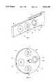
- FIG. 4shows another alternative embodiment analogous to FIG. 3.
- a wheel 120performs the same function as the sliding member 80 of FIG. 3.
- Wheel 120carries the various portions 130, 140, 150 and 160, which again may be either standard target elements differing in composition, or apertures differing in diameter, or integrated combinations of standard target elements and apertures.
- Wheel 120is rotated about its axis 165 to bring the appropriate portions 130, 140, 150, or 160 into play for a particular calibration situation.
- the detent notches 125, 135, 145 and 155provide for stable and reproducible positioning of the selected portions 130, 140, 150, or 160 respectively at the active position in the housing, facing the fluorescence detector.
- Either the sliding member 80 of FIG. 3 or the wheel of FIG. 4may be operated by hand by the user of the calibration apparatus, or may be operated by an actuator, such as a spring 180, an electric motor 166, an ultrasonic motor, a piezoelectric linear actuator 115 or other mechanical aid.
- an actuatorsuch as a spring 180, an electric motor 166, an ultrasonic motor, a piezoelectric linear actuator 115 or other mechanical aid.
- FIG. 5shows a detail of another embodiment of the calibration standard which is useful for calibration of fluorescence detectors requiring a dynamic calibration rather than a static calibration, such as in calibration of fluorescent bar code scanners.
- a slide 80 in FIG. 5carries a standard target element 170, an example of a specific type of the standard target element 20 of FIG. 1.
- the element 170 in FIG. 5is shown as a bar code, but may be any indicia or pattern of fluorescent and non-fluorescent substances intended to be read using a fluorescence detector.
- the purpose of slide 80is to carry the standard target element, moving it from a starting position in housing 10 in a predetermined time to an ending position during a dynamic calibration.
- the calibration apparatus of this inventionincludes means of moving the standard target element and returning it to its starting position.
- the movementis preferably made parallel to the standard target element and perpendicular to the axis of the calibration apparatus, which lies in the plane of drawing FIGS. 1 and 2.
- FIG. 6shows a slide 80 carrying indicia 170, such as the bar code shown in the figure.
- Springs 180 on both edges of slide 80act to move slide 80, when slide 80 is released from a detent or latched position (not shown).
- Springs 180are fixed to bosses 190, which are in turn fixed to housing 10.
- the bosses 190also serve to guide slide 80 as it moves.
- the springsare preferably used to move slide 80 during the dynamic calibration to provide a reproducible time for transit from a first position to a second position.
- slide 80can be returned by hand to its first position by the operator of the calibration apparatus.
- slide 80is accomplished by a motor 166, linear actuator 115, relay, or other mechanical aid.
- a wheellike wheel 120 of FIG. 4, instead of slide 80 of FIG. 5 to move the standard target element for dynamic calibrations.
- Slide 80 of FIGS. 5 and 6, or a wheel equivalent as in FIG. 4can have detent notches like notch 85 or notch 125 to provide stable, reproducible starting and ending points of the movement, and can have ratchet elements (not shown) to latch the dynamic standard target element at a starting position when not being moved for a dynamic calibration.
- FIG. 7shows an embodiment of the calibration apparatus incorporating an additional feature useful for calibrating some fluorescence detectors.
- an additional input port 200allows additional light to be selectively introduced into housing 10 to simulate during calibration the ambient light environment in which the fluorescence detector is to be used.
- Input port 200is preferably a fiber-optic input connector accepting an optical fiber 210, which carries the additional light into housing 10.
- Input port 200may be disposed to direct the additional light directly toward the fluorescent detector's optical front end 70 as shown, or alternatively may be disposed to illuminate the standard target element 20 and/or other portions of the interior of housing 10. In the latter case the additional light introduced through input port 200 reaches the fluorescent detector by reflection or scattering which may more realistically simulate the ambient lighting situation for some applications.
- FIG. 8shows a detail of a preferred embodiment for the adapter portion 60 of the calibration apparatus.
- a bayonet-type coupling member 220is used on adapter portion 60, mating with corresponding bayonet-type coupling member 230, attached to or integral with the optical front end 70 of the fluorescence detector with which the calibration apparatus is to be used.
- a quick-coupling connector or adaptersuch as elements 220 and 230 allows the calibration apparatus of this invention to be used with a variety of different fluorescence detector models and provides for easy use during calibration.
- the use of the calibration apparatus and of the methods of this inventionis straightforward.
- detection specifications for a fluorescence detectorare established by a manufacturer, those specifications are translated into a standard target element for either static or dynamic calibration, depending on the application of the fluorescence detector.
- the specificationsmay require a set of standard target elements to calibrate to more than one specification.
- the setcan include a low calibration standard element and a high calibration standard element to cover the range of detection intensities of a detector.
- the userattaches the pre-set calibration standard to the fluorescence detector and makes a fluorescence reading for each calibration condition using the appropriate standard target element, and adjusts the fluorescence detector output to match the correct calibration.
- the procedureis the same for dynamic calibration, which, in the simplest embodiments of the calibration apparatus, require the user to initiate movement of the dynamic standard target element.
- the target element movement for dynamic calibrationis automated.
Landscapes
- Physics & Mathematics (AREA)
- General Physics & Mathematics (AREA)
- Spectroscopy & Molecular Physics (AREA)
- Engineering & Computer Science (AREA)
- General Health & Medical Sciences (AREA)
- Theoretical Computer Science (AREA)
- Life Sciences & Earth Sciences (AREA)
- Health & Medical Sciences (AREA)
- Mathematical Physics (AREA)
- Biochemistry (AREA)
- Analytical Chemistry (AREA)
- Chemical & Material Sciences (AREA)
- Immunology (AREA)
- Pathology (AREA)
- Electromagnetism (AREA)
- Toxicology (AREA)
- Artificial Intelligence (AREA)
- Computer Vision & Pattern Recognition (AREA)
- Sustainable Development (AREA)
- Investigating, Analyzing Materials By Fluorescence Or Luminescence (AREA)
Abstract
Description
Claims (34)
Priority Applications (1)
| Application Number | Priority Date | Filing Date | Title |
|---|---|---|---|
| US08/156,249US5414258A (en) | 1993-11-22 | 1993-11-22 | Apparatus and method for calibration of fluorescence detectors |
Applications Claiming Priority (1)
| Application Number | Priority Date | Filing Date | Title |
|---|---|---|---|
| US08/156,249US5414258A (en) | 1993-11-22 | 1993-11-22 | Apparatus and method for calibration of fluorescence detectors |
Publications (1)
| Publication Number | Publication Date |
|---|---|
| US5414258Atrue US5414258A (en) | 1995-05-09 |
Family
ID=22558752
Family Applications (1)
| Application Number | Title | Priority Date | Filing Date |
|---|---|---|---|
| US08/156,249Expired - LifetimeUS5414258A (en) | 1993-11-22 | 1993-11-22 | Apparatus and method for calibration of fluorescence detectors |
Country Status (1)
| Country | Link |
|---|---|
| US (1) | US5414258A (en) |
Cited By (63)
| Publication number | Priority date | Publication date | Assignee | Title |
|---|---|---|---|---|
| US5719948A (en)* | 1994-06-24 | 1998-02-17 | Angstrom Technologies, Inc. | Apparatus and methods for fluorescent imaging and optical character reading |
| US5773808A (en)* | 1996-05-17 | 1998-06-30 | Laser; Vadim | Method and apparatus for reading invisible messages |
| WO1998028592A1 (en)* | 1996-12-23 | 1998-07-02 | Ruprecht-Karls-Universität Heidelberg | Method and devices for measuring distances between object structures |
| US5838435A (en)* | 1997-10-20 | 1998-11-17 | Sandia Corporation | Calibration method for spectroscopic systems |
| WO1999008221A1 (en)* | 1997-08-05 | 1999-02-18 | Cimatrix | Uniform ultraviolet strobe illuminator and method of using same |
| US5902246A (en)* | 1996-03-26 | 1999-05-11 | Lifespex, Incorporated | Method and apparatus for calibrating an optical probe |
| USD414480S (en) | 1998-03-20 | 1999-09-28 | Cimatrix | Strobe lamp illuminator |
| RU2142619C1 (en)* | 1998-11-05 | 1999-12-10 | Московский областной научно-исследовательский клинический институт | Gear calibrating medicinal diagnostic spectrophotometric devices |
| US6119071A (en)* | 1996-06-28 | 2000-09-12 | Battelle Memorial Institute | Edge effect compensating bar code reader |
| US6165609A (en)* | 1998-10-30 | 2000-12-26 | Avery Dennison Corporation | Security coatings for label materials |
| WO2001028006A2 (en) | 1999-10-12 | 2001-04-19 | Angstrom Technologies, Inc. | Black light sources and methods for excitation of fluorescence |
| EP1162450A1 (en)* | 2000-06-07 | 2001-12-12 | F. Hoffmann-La Roche Ag | Reference device for evaluating the performance of a confocal laser scanning microscope, and a method and system for performing that evaluation |
| US20030002028A1 (en)* | 2001-05-17 | 2003-01-02 | Rice Bradley W. | Method and apparatus for determining target depth, brightness and size within a body region |
| US20030011701A1 (en)* | 2001-07-13 | 2003-01-16 | David Nilson | Multi-view imaging apparatus |
| US20030036860A1 (en)* | 2001-06-20 | 2003-02-20 | Xenogen Corporation | Absolute intensity determination for a light source in low level light imaging systems |
| WO2003023379A1 (en)* | 2001-09-12 | 2003-03-20 | Apprise Technologies, Inc. | Multichannel fluorosensor |
| US20030076268A1 (en)* | 2001-10-22 | 2003-04-24 | Filtronic Lk Oy | Internal multiband antenna |
| US20030146663A1 (en)* | 2002-02-06 | 2003-08-07 | Xenogen Corporation | Light calibration device for use in low level light imaging systems |
| US20030154976A1 (en)* | 2002-02-20 | 2003-08-21 | Xenogen Corporation | Multiple output anesthesia system |
| US20030193517A1 (en)* | 1999-11-15 | 2003-10-16 | Xenogen Corporation | Graphical user interface for in-vivo imaging |
| US20040021771A1 (en)* | 2002-07-16 | 2004-02-05 | Xenogen Corporation | Method and apparatus for 3-D imaging of internal light sources |
| US20040020993A1 (en)* | 2001-12-28 | 2004-02-05 | Green Larry R. | Method for luminescent identification and calibration |
| WO2003001163A3 (en)* | 2001-06-20 | 2004-02-12 | Xenogen Corp | Absolute intensity determination for a light source in low level light imaging systems |
| US20040060987A1 (en)* | 2002-05-07 | 2004-04-01 | Green Larry R. | Digital image analysis method for enhanced and optimized signals in fluorophore detection |
| US6767733B1 (en) | 2001-10-10 | 2004-07-27 | Pritest, Inc. | Portable biosensor apparatus with controlled flow |
| US20040196455A1 (en)* | 2001-03-28 | 2004-10-07 | Eugen Ermantraut | Device for referencing fluorescence signals |
| US20040233465A1 (en)* | 2003-04-04 | 2004-11-25 | Angstrom Technologies, Inc. | Methods and ink compositions for invisibly printed security images having multiple authentication features |
| US20050025338A1 (en)* | 2002-11-04 | 2005-02-03 | Mediasec Technologies Gmbh | Apparatus and methods for improving detection of watermarks in content that has undergone a lossy transformation |
| US20050028482A1 (en)* | 2003-07-01 | 2005-02-10 | Xenogen Corporation | Multi-mode internal imaging |
| US6861251B2 (en) | 2003-02-24 | 2005-03-01 | Pritest, Inc. | Translucent solid matrix assay device for microarray analysis |
| US20050149877A1 (en)* | 1999-11-15 | 2005-07-07 | Xenogen Corporation | Graphical user interface for 3-D in-vivo imaging |
| US20050145786A1 (en)* | 2002-02-06 | 2005-07-07 | Xenogen Corporation | Phantom calibration device for low level light imaging systems |
| US20050148846A1 (en)* | 2000-02-25 | 2005-07-07 | Xenogen Corporation | Imaging apparatus |
| US20050219535A1 (en)* | 2002-02-22 | 2005-10-06 | Xenogen Corporation | Bottom fluorescence illumination assembly for an imaging apparatus |
| US20050237423A1 (en)* | 2001-07-13 | 2005-10-27 | Xenogen Corporation | Structured light imaging apparatus |
| US20050287040A1 (en)* | 2004-06-29 | 2005-12-29 | Molecular Devices Corporation | Fluorescence validation plate |
| US20060121614A1 (en)* | 2001-09-12 | 2006-06-08 | Hitachi, Ltd. | Multichannel fluorosensor |
| US20060163492A1 (en)* | 2002-11-11 | 2006-07-27 | Forschungszentrum Julich Gmbh | Method for encoding items of information and a device and method for evaluating the encoded information |
| US20060203243A1 (en)* | 2002-02-22 | 2006-09-14 | Xenogen Corporation | Illumination system for an imaging apparatus with low profile output device |
| US20060203244A1 (en)* | 2002-02-22 | 2006-09-14 | Xenogen Corporation | Dual illumination system for an imaging apparatus and method |
| RU2284026C1 (en)* | 2005-03-18 | 2006-09-20 | Государственное учреждение Московский областной научно-исследовательский клинический институт им. М.Ф. Владимирского (МОНИКИ) | Device for calibration of medical diagnostic spectrophotometric devices |
| US20060208199A1 (en)* | 2005-03-18 | 2006-09-21 | Uvp Inc. | Luminescent calibration |
| US20060268153A1 (en)* | 2005-05-11 | 2006-11-30 | Xenogen Corporation | Surface contruction using combined photographic and structured light information |
| US20070200058A1 (en)* | 2002-02-06 | 2007-08-30 | Caliper Life Sciences, Inc. | Fluorescent phantom device |
| FR2899688A1 (en)* | 2006-04-11 | 2007-10-12 | Banque De France | CALIBRATION DEVICE FOR SECURE DOCUMENT CONTROL APPARATUS |
| US20070253908A1 (en)* | 2002-07-16 | 2007-11-01 | Xenogen Corporation | Fluorescent light tomography |
| US20080052052A1 (en)* | 2006-08-24 | 2008-02-28 | Xenogen Corporation | Apparatus and methods for determining optical tissue properties |
| US20090059252A1 (en)* | 2007-08-21 | 2009-03-05 | William Coyle | Stable Emissive Toner Composition System and Method |
| US20100084572A1 (en)* | 2006-06-01 | 2010-04-08 | Ecolab Inc. | Uv fluorometric sensor and method for using the same |
| RU2389083C1 (en)* | 2008-11-21 | 2010-05-10 | Государственное учреждение Московский областной научно-исследовательский клинический институт им. М.Ф. Владимирского (МОНИКИ им. М.Ф. Владимирского) | Method of creation of model simulating optical properties of living biological tissues |
| US20130123643A1 (en)* | 2010-04-12 | 2013-05-16 | Holger Jungmann | Measuring arrangement for recording a spectrum, in particular from vital tissue |
| WO2013188238A1 (en)* | 2012-06-14 | 2013-12-19 | Gen-Probe Incorporated | Use of a fluorescent material to detect failure or deteriorated performance of a fluorometer |
| EP2587237A4 (en)* | 2010-06-25 | 2014-07-02 | Univ Tsinghua | METHOD FOR AUTOMATICALLY CALIBRATING RAMAN SPECTROSCOPY DETECTION SYSTEM AND RAMAN SPECTROSCOPY DETECTION SYSTEM |
| US8901516B2 (en) | 2010-09-01 | 2014-12-02 | Spectral Instruments Imaging, LLC | Excitation light source assembly |
| WO2015085189A1 (en)* | 2013-12-06 | 2015-06-11 | Quidel Corporation | Method for reducing analyzer variability using a normalization target |
| DE102013114399A1 (en)* | 2013-12-18 | 2015-06-18 | Endress + Hauser Conducta Gesellschaft für Mess- und Regeltechnik mbH + Co. KG | Method for calibrating and / or adjusting a sensor and optical sensor |
| US9207181B2 (en) | 2012-03-01 | 2015-12-08 | Quidel Corporation | System and apparatus for point-of-care diagnostics |
| US9347894B2 (en) | 2010-09-01 | 2016-05-24 | Spectral Instruments Imaging, LLC | Methods and systems for producing visible light and x-ray image data |
| EP3399300A1 (en) | 2017-05-02 | 2018-11-07 | QIAGEN Lake Constance GmbH | Fluorescence reference sample arrangement including an excitation filter and an emission filter |
| WO2018217580A1 (en) | 2017-05-20 | 2018-11-29 | Honeywell International Inc. Intellectual Property-Patent Services | Milk lumilux dispersion |
| RU2730426C2 (en)* | 2015-04-16 | 2020-08-21 | Хераеус Электро-Ните Интернациональ Н.В. | Method of spectrometer calibration and reference material |
| US11061020B2 (en) | 2012-03-01 | 2021-07-13 | Quidel Corporation | Interactive test device and apparatus with timing mechanism |
| US11730370B2 (en) | 2006-08-24 | 2023-08-22 | Xenogen Corporation | Spectral unmixing for in-vivo imaging |
Citations (5)
| Publication number | Priority date | Publication date | Assignee | Title |
|---|---|---|---|---|
| US4302678A (en)* | 1980-01-25 | 1981-11-24 | Magnaflux Corporation | Fluorescent standard for scanning devices |
| US4662745A (en)* | 1986-02-05 | 1987-05-05 | Atlantic Richfield Company | Reflectance and luminescence calibration plate having a near-Lambertian surface and method for making the same |
| US5089709A (en)* | 1990-10-11 | 1992-02-18 | Dentsply Venture Capital Associates, L.P. | Test system viewer for fluorescence evaluation |
| US5093234A (en)* | 1984-12-24 | 1992-03-03 | Caribbean Microparticles Corporation | Method of aligning, compensating, and calibrating a flow cytometer for analysis of samples, and microbead standards kit therefor |
| US5125747A (en)* | 1990-10-12 | 1992-06-30 | Tytronics, Inc. | Optical analytical instrument and method having improved calibration |
- 1993
- 1993-11-22USUS08/156,249patent/US5414258A/ennot_activeExpired - Lifetime
Patent Citations (5)
| Publication number | Priority date | Publication date | Assignee | Title |
|---|---|---|---|---|
| US4302678A (en)* | 1980-01-25 | 1981-11-24 | Magnaflux Corporation | Fluorescent standard for scanning devices |
| US5093234A (en)* | 1984-12-24 | 1992-03-03 | Caribbean Microparticles Corporation | Method of aligning, compensating, and calibrating a flow cytometer for analysis of samples, and microbead standards kit therefor |
| US4662745A (en)* | 1986-02-05 | 1987-05-05 | Atlantic Richfield Company | Reflectance and luminescence calibration plate having a near-Lambertian surface and method for making the same |
| US5089709A (en)* | 1990-10-11 | 1992-02-18 | Dentsply Venture Capital Associates, L.P. | Test system viewer for fluorescence evaluation |
| US5125747A (en)* | 1990-10-12 | 1992-06-30 | Tytronics, Inc. | Optical analytical instrument and method having improved calibration |
Non-Patent Citations (2)
| Title |
|---|
| West et al., "Practical Standards for UV Absorption and Fluorescence Spectrophotometry--Developments in Photophysical Instrumentation Part 3", American Laboratory, 9(3), Mar. 1977, pp. 37-52. |
| West et al., Practical Standards for UV Absorption and Fluorescence Spectrophotometry Developments in Photophysical Instrumentation Part 3 , American Laboratory, 9(3), Mar. 1977, pp. 37 52.* |
Cited By (157)
| Publication number | Priority date | Publication date | Assignee | Title |
|---|---|---|---|---|
| US5719948A (en)* | 1994-06-24 | 1998-02-17 | Angstrom Technologies, Inc. | Apparatus and methods for fluorescent imaging and optical character reading |
| US5902246A (en)* | 1996-03-26 | 1999-05-11 | Lifespex, Incorporated | Method and apparatus for calibrating an optical probe |
| US5773808A (en)* | 1996-05-17 | 1998-06-30 | Laser; Vadim | Method and apparatus for reading invisible messages |
| US6119071A (en)* | 1996-06-28 | 2000-09-12 | Battelle Memorial Institute | Edge effect compensating bar code reader |
| US6424421B1 (en)* | 1996-12-23 | 2002-07-23 | Ruprecht-Karls-Universität Heidelberg | Method and devices for measuring distances between object structures |
| WO1998028592A1 (en)* | 1996-12-23 | 1998-07-02 | Ruprecht-Karls-Universität Heidelberg | Method and devices for measuring distances between object structures |
| WO1999008221A1 (en)* | 1997-08-05 | 1999-02-18 | Cimatrix | Uniform ultraviolet strobe illuminator and method of using same |
| US6032860A (en)* | 1997-08-05 | 2000-03-07 | Ci-Matrix | Uniform ultraviolet strobe illuminator and method of using same |
| US5838435A (en)* | 1997-10-20 | 1998-11-17 | Sandia Corporation | Calibration method for spectroscopic systems |
| USD414480S (en) | 1998-03-20 | 1999-09-28 | Cimatrix | Strobe lamp illuminator |
| US6165609A (en)* | 1998-10-30 | 2000-12-26 | Avery Dennison Corporation | Security coatings for label materials |
| RU2142619C1 (en)* | 1998-11-05 | 1999-12-10 | Московский областной научно-исследовательский клинический институт | Gear calibrating medicinal diagnostic spectrophotometric devices |
| WO2001028006A2 (en) | 1999-10-12 | 2001-04-19 | Angstrom Technologies, Inc. | Black light sources and methods for excitation of fluorescence |
| US20030193517A1 (en)* | 1999-11-15 | 2003-10-16 | Xenogen Corporation | Graphical user interface for in-vivo imaging |
| US20100260395A1 (en)* | 1999-11-15 | 2010-10-14 | Xenogen Corporation | Graphical user interface for in-vivo imaging |
| US8734342B2 (en) | 1999-11-15 | 2014-05-27 | Xenogen Corporation | Graphical user interface for in-vivo imaging |
| US20050149877A1 (en)* | 1999-11-15 | 2005-07-07 | Xenogen Corporation | Graphical user interface for 3-D in-vivo imaging |
| US20080134074A1 (en)* | 1999-11-15 | 2008-06-05 | Xenogen Corporation | Graphical user interface for in-vivo imaging |
| US7765487B2 (en) | 1999-11-15 | 2010-07-27 | Xenogen Corporation | Graphical user interface for in-vivo imaging |
| US7581191B2 (en) | 1999-11-15 | 2009-08-25 | Xenogen Corporation | Graphical user interface for 3-D in-vivo imaging |
| US7299420B2 (en) | 1999-11-15 | 2007-11-20 | Xenogen Corporation | Graphical user interface for in-vivo imaging |
| US20050219407A1 (en)* | 2000-02-25 | 2005-10-06 | Xenogen Corporation | Imaging apparatus with selectable optical filters |
| US7383078B2 (en) | 2000-02-25 | 2008-06-03 | Xenogen Corporation | Imaging apparatus with heating element |
| US7949383B2 (en) | 2000-02-25 | 2011-05-24 | Xenogen Corporation | Imaging apparatus with selectable moveable stage |
| US20050148846A1 (en)* | 2000-02-25 | 2005-07-07 | Xenogen Corporation | Imaging apparatus |
| US20050219358A1 (en)* | 2000-02-25 | 2005-10-06 | Xenogen Corporation | Imaging apparatus with a gas manifold |
| US20050219373A1 (en)* | 2000-02-25 | 2005-10-06 | Xenogen Corporation | Imaging apparatus with magnetic elements |
| US20040051050A1 (en)* | 2000-06-07 | 2004-03-18 | Schmid Karl Anton Josef | Reference device for evaluating the performance of a confocal laser scanning microscope, and a method and system for performing that evaluation |
| US7053384B2 (en) | 2000-06-07 | 2006-05-30 | Roche Molecular Systems, Inc. | Reference device for evaluating the performance of a confocal laser scanning microscope, and a method and system for performing that evaluation |
| WO2001094918A1 (en)* | 2000-06-07 | 2001-12-13 | Roche Diagnostics Gmbh | Reference device for evaluating the performance of a confocal laser scanning microscope, and a method and system for performing that evaluation |
| EP1162450A1 (en)* | 2000-06-07 | 2001-12-12 | F. Hoffmann-La Roche Ag | Reference device for evaluating the performance of a confocal laser scanning microscope, and a method and system for performing that evaluation |
| AU2002247765B2 (en)* | 2001-03-28 | 2007-04-26 | Clondiag Chip Technologies Gmbh | Device for referencing fluorescence signals |
| US20040196455A1 (en)* | 2001-03-28 | 2004-10-07 | Eugen Ermantraut | Device for referencing fluorescence signals |
| EP1373870B1 (en)* | 2001-03-28 | 2007-07-11 | Clondiag Chip Technologies GmbH | Device for referencing fluorescence signals |
| US7262842B2 (en) | 2001-03-28 | 2007-08-28 | Clondiag Chip Technologies Gmbh | Device for referencing fluorescence signals |
| US20030002028A1 (en)* | 2001-05-17 | 2003-01-02 | Rice Bradley W. | Method and apparatus for determining target depth, brightness and size within a body region |
| US7403812B2 (en) | 2001-05-17 | 2008-07-22 | Xenogen Corporation | Method and apparatus for determining target depth, brightness and size within a body region |
| US8180435B2 (en) | 2001-05-17 | 2012-05-15 | Xenogen Corporation | Method and apparatus for determining target depth, brightness and size within a body region |
| US20070270697A1 (en)* | 2001-05-17 | 2007-11-22 | Xenogen Corporation | Method and apparatus for determining target depth, brightness and size within a body region |
| US8825140B2 (en) | 2001-05-17 | 2014-09-02 | Xenogen Corporation | Imaging system |
| US7764986B2 (en) | 2001-05-17 | 2010-07-27 | Xenogen Corporation | Method and apparatus for determining target depth, brightness and size within a body region |
| US20100262019A1 (en)* | 2001-05-17 | 2010-10-14 | Xenogen Corporation | Method and apparatus for determining target depth, brightness and size within a body region |
| US20070013780A1 (en)* | 2001-06-20 | 2007-01-18 | Xenogen Corporation | Absolute intensity determination for a light source in low level light imaging systems |
| US20030036860A1 (en)* | 2001-06-20 | 2003-02-20 | Xenogen Corporation | Absolute intensity determination for a light source in low level light imaging systems |
| US7663664B2 (en) | 2001-06-20 | 2010-02-16 | Xenogen Corporation | Absolute intensity determination for a fluorescent light source in low level light imaging systems |
| WO2003001163A3 (en)* | 2001-06-20 | 2004-02-12 | Xenogen Corp | Absolute intensity determination for a light source in low level light imaging systems |
| US7116354B2 (en) | 2001-06-20 | 2006-10-03 | Xenogen Corporation | Absolute intensity determination for a light source in low level light imaging systems |
| US7113217B2 (en) | 2001-07-13 | 2006-09-26 | Xenogen Corporation | Multi-view imaging apparatus |
| US20080079802A1 (en)* | 2001-07-13 | 2008-04-03 | Xenogen Corporation | Structured light imaging apparatus |
| US7595838B2 (en) | 2001-07-13 | 2009-09-29 | Xenogen Corporation | Multi-view imaging apparatus |
| US8279334B2 (en) | 2001-07-13 | 2012-10-02 | Xenogen Corporation | Structured light imaging apparatus |
| US7589786B2 (en) | 2001-07-13 | 2009-09-15 | Xenogen Corporation | Multi-view imaging of a sample in a box |
| US20030011701A1 (en)* | 2001-07-13 | 2003-01-16 | David Nilson | Multi-view imaging apparatus |
| US20050237423A1 (en)* | 2001-07-13 | 2005-10-27 | Xenogen Corporation | Structured light imaging apparatus |
| US20060250517A1 (en)* | 2001-07-13 | 2006-11-09 | Xenogen Corporation | Multi-view imaging apparatus |
| US20060250518A1 (en)* | 2001-07-13 | 2006-11-09 | Xenogen Corporation | Multi-view imaging apparatus |
| US7298415B2 (en) | 2001-07-13 | 2007-11-20 | Xenogen Corporation | Structured light imaging apparatus |
| US20060121614A1 (en)* | 2001-09-12 | 2006-06-08 | Hitachi, Ltd. | Multichannel fluorosensor |
| WO2003023379A1 (en)* | 2001-09-12 | 2003-03-20 | Apprise Technologies, Inc. | Multichannel fluorosensor |
| US7416701B2 (en)* | 2001-09-12 | 2008-08-26 | Ecolab Inc. | Calibrator for fluorosensor |
| US6767733B1 (en) | 2001-10-10 | 2004-07-27 | Pritest, Inc. | Portable biosensor apparatus with controlled flow |
| US20030076268A1 (en)* | 2001-10-22 | 2003-04-24 | Filtronic Lk Oy | Internal multiband antenna |
| US20040020993A1 (en)* | 2001-12-28 | 2004-02-05 | Green Larry R. | Method for luminescent identification and calibration |
| US20030146663A1 (en)* | 2002-02-06 | 2003-08-07 | Xenogen Corporation | Light calibration device for use in low level light imaging systems |
| US6919919B2 (en) | 2002-02-06 | 2005-07-19 | Xenogen Corporation | Light calibration device for use in low level light imaging systems |
| US20050145786A1 (en)* | 2002-02-06 | 2005-07-07 | Xenogen Corporation | Phantom calibration device for low level light imaging systems |
| US7629573B2 (en) | 2002-02-06 | 2009-12-08 | Xenogen Corporation | Tissue phantom calibration device for low level light imaging systems |
| US7649185B2 (en) | 2002-02-06 | 2010-01-19 | Xenogen Corporation | Fluorescent phantom device |
| US20070200058A1 (en)* | 2002-02-06 | 2007-08-30 | Caliper Life Sciences, Inc. | Fluorescent phantom device |
| US20080099020A1 (en)* | 2002-02-20 | 2008-05-01 | Xenogen Corporation | Living specimen induction chamber |
| US20030154976A1 (en)* | 2002-02-20 | 2003-08-21 | Xenogen Corporation | Multiple output anesthesia system |
| US7806082B2 (en) | 2002-02-20 | 2010-10-05 | Xenogen Corporation | Living specimen induction chamber |
| US7461652B2 (en) | 2002-02-20 | 2008-12-09 | Xenogen Corporation | Imaging system with anesthesia system |
| US7464707B2 (en) | 2002-02-20 | 2008-12-16 | Xenogen Corporation | Anesthesia delivery device for use in a light imaging system |
| US7503323B2 (en) | 2002-02-20 | 2009-03-17 | Xenogen Corporation | Multiple output anesthesia system |
| US20030209244A1 (en)* | 2002-02-20 | 2003-11-13 | Xenogen Corporation | Living specimen induction chamber |
| US7331341B2 (en) | 2002-02-20 | 2008-02-19 | Xenogen Corporation | Living specimen induction chamber |
| US20070089742A1 (en)* | 2002-02-20 | 2007-04-26 | Xenogen Corporation | Imaging system with anesthesia system |
| US7177024B2 (en) | 2002-02-22 | 2007-02-13 | Xenogen Corporation | Bottom fluorescence illumination assembly for an imaging apparatus |
| US7474398B2 (en) | 2002-02-22 | 2009-01-06 | Xenogen Corporation | Illumination system for an imaging apparatus with low profile output device |
| US7474399B2 (en) | 2002-02-22 | 2009-01-06 | Xenogen Corporation | Dual illumination system for an imaging apparatus and method |
| US20060203243A1 (en)* | 2002-02-22 | 2006-09-14 | Xenogen Corporation | Illumination system for an imaging apparatus with low profile output device |
| US20060203244A1 (en)* | 2002-02-22 | 2006-09-14 | Xenogen Corporation | Dual illumination system for an imaging apparatus and method |
| US20050219535A1 (en)* | 2002-02-22 | 2005-10-06 | Xenogen Corporation | Bottom fluorescence illumination assembly for an imaging apparatus |
| US7466418B2 (en) | 2002-02-22 | 2008-12-16 | Xenogen Corporation | Fluorescence illumination assembly for an imaging apparatus and method |
| US20040060987A1 (en)* | 2002-05-07 | 2004-04-01 | Green Larry R. | Digital image analysis method for enhanced and optimized signals in fluorophore detection |
| US20050201614A1 (en)* | 2002-07-16 | 2005-09-15 | Xenogen Corporation | 3-D in-vivo imaging and topography using structured light |
| US8909326B2 (en) | 2002-07-16 | 2014-12-09 | Xenogen Corporation | Method and apparatus for 3-D imaging of internal light sources |
| US20080031494A1 (en)* | 2002-07-16 | 2008-02-07 | Xenogen Corporation | Fluorescent light tomography |
| US20110090316A1 (en)* | 2002-07-16 | 2011-04-21 | Xenogen Corporation | Method and apparatus for 3-d imaging of internal light sources |
| US20080018899A1 (en)* | 2002-07-16 | 2008-01-24 | Xenogen Corporation | Method and apparatus for 3-d imaging of internal light sources |
| US7555332B2 (en) | 2002-07-16 | 2009-06-30 | Xenogen Corporation | Fluorescent light tomography |
| US20070253908A1 (en)* | 2002-07-16 | 2007-11-01 | Xenogen Corporation | Fluorescent light tomography |
| US7860549B2 (en) | 2002-07-16 | 2010-12-28 | Xenogen Corporation | Method and apparatus for 3-D imaging of internal light sources |
| US7797034B2 (en) | 2002-07-16 | 2010-09-14 | Xenogen Corporation | 3-D in-vivo imaging and topography using structured light |
| US7599731B2 (en) | 2002-07-16 | 2009-10-06 | Xenogen Corporation | Fluorescent light tomography |
| US7603167B2 (en) | 2002-07-16 | 2009-10-13 | Xenogen Corporation | Method and apparatus for 3-D imaging of internal light sources |
| US7616985B2 (en) | 2002-07-16 | 2009-11-10 | Xenogen Corporation | Method and apparatus for 3-D imaging of internal light sources |
| US20040021771A1 (en)* | 2002-07-16 | 2004-02-05 | Xenogen Corporation | Method and apparatus for 3-D imaging of internal light sources |
| US20100022872A1 (en)* | 2002-07-16 | 2010-01-28 | Xenogen Corporation | Method and apparatus for 3-d imaging of internal light sources |
| US20050025338A1 (en)* | 2002-11-04 | 2005-02-03 | Mediasec Technologies Gmbh | Apparatus and methods for improving detection of watermarks in content that has undergone a lossy transformation |
| EP1416440A3 (en)* | 2002-11-04 | 2005-08-17 | Mediasec Technologies GmbH | Apparatus and methods for improving detection of watermarks in content that has undergone a lossy transformation |
| US7630511B2 (en) | 2002-11-04 | 2009-12-08 | Thomson Licensing | Apparatus and methods for improving detection of watermarks in content that has undergone a lossy transformation |
| US20060163492A1 (en)* | 2002-11-11 | 2006-07-27 | Forschungszentrum Julich Gmbh | Method for encoding items of information and a device and method for evaluating the encoded information |
| US6861251B2 (en) | 2003-02-24 | 2005-03-01 | Pritest, Inc. | Translucent solid matrix assay device for microarray analysis |
| US8717625B2 (en) | 2003-04-04 | 2014-05-06 | Angstrom Technologies, Inc. | Emissive image substrate marking, articles marked with an emissive image, and authentication methods involving the same |
| US20040233465A1 (en)* | 2003-04-04 | 2004-11-25 | Angstrom Technologies, Inc. | Methods and ink compositions for invisibly printed security images having multiple authentication features |
| US7821675B2 (en) | 2003-04-04 | 2010-10-26 | Angstrom Technologies, Inc. | Methods and ink compositions for invisibly printed security images having multiple authentication features |
| US20060253013A1 (en)* | 2003-07-01 | 2006-11-09 | Xenogen Corporation | Multi-mode internal imaging |
| US7190991B2 (en) | 2003-07-01 | 2007-03-13 | Xenogen Corporation | Multi-mode internal imaging |
| US9008758B2 (en) | 2003-07-01 | 2015-04-14 | Xenogen Corporation | Multi-mode internal imaging |
| US7813782B2 (en) | 2003-07-01 | 2010-10-12 | Xenogen Corporation | Imaging system including an object handling system |
| US20060258941A1 (en)* | 2003-07-01 | 2006-11-16 | Xenogen Corporation | Multi-mode internal imaging |
| US20050028482A1 (en)* | 2003-07-01 | 2005-02-10 | Xenogen Corporation | Multi-mode internal imaging |
| US7881773B2 (en) | 2003-07-01 | 2011-02-01 | Xenogen Corporation | Multi-mode internal imaging |
| US20110092813A1 (en)* | 2003-07-01 | 2011-04-21 | Xenogen Corporation | Multi-mode internal imaging |
| US20050287040A1 (en)* | 2004-06-29 | 2005-12-29 | Molecular Devices Corporation | Fluorescence validation plate |
| RU2284026C1 (en)* | 2005-03-18 | 2006-09-20 | Государственное учреждение Московский областной научно-исследовательский клинический институт им. М.Ф. Владимирского (МОНИКИ) | Device for calibration of medical diagnostic spectrophotometric devices |
| US20060208199A1 (en)* | 2005-03-18 | 2006-09-21 | Uvp Inc. | Luminescent calibration |
| US8044996B2 (en) | 2005-05-11 | 2011-10-25 | Xenogen Corporation | Surface construction using combined photographic and structured light information |
| US20060268153A1 (en)* | 2005-05-11 | 2006-11-30 | Xenogen Corporation | Surface contruction using combined photographic and structured light information |
| FR2899688A1 (en)* | 2006-04-11 | 2007-10-12 | Banque De France | CALIBRATION DEVICE FOR SECURE DOCUMENT CONTROL APPARATUS |
| US20100084572A1 (en)* | 2006-06-01 | 2010-04-08 | Ecolab Inc. | Uv fluorometric sensor and method for using the same |
| US8084756B2 (en) | 2006-06-01 | 2011-12-27 | Ecolab Inc. | UV fluorometric sensor and method for using the same |
| US7989780B2 (en) | 2006-06-01 | 2011-08-02 | Ecolab Inc. | UV fluorometric sensor and method for using the same |
| US20080052052A1 (en)* | 2006-08-24 | 2008-02-28 | Xenogen Corporation | Apparatus and methods for determining optical tissue properties |
| US11730370B2 (en) | 2006-08-24 | 2023-08-22 | Xenogen Corporation | Spectral unmixing for in-vivo imaging |
| US10775308B2 (en) | 2006-08-24 | 2020-09-15 | Xenogen Corporation | Apparatus and methods for determining optical tissue properties |
| US9470997B2 (en) | 2007-08-21 | 2016-10-18 | Angstrom Technologies, Inc. | Stable emissive toner composition system and method |
| US10082744B2 (en) | 2007-08-21 | 2018-09-25 | Angstrom Technologies, Inc. | Stable emissive toner composition system and method |
| US9823594B2 (en) | 2007-08-21 | 2017-11-21 | Angstrom Technologies, Inc. | Stable emissive toner composition system and method |
| US9104126B2 (en) | 2007-08-21 | 2015-08-11 | Angstrom Technologies, Inc. | Stable emissive toner composition system and method |
| US20090059252A1 (en)* | 2007-08-21 | 2009-03-05 | William Coyle | Stable Emissive Toner Composition System and Method |
| RU2389083C1 (en)* | 2008-11-21 | 2010-05-10 | Государственное учреждение Московский областной научно-исследовательский клинический институт им. М.Ф. Владимирского (МОНИКИ им. М.Ф. Владимирского) | Method of creation of model simulating optical properties of living biological tissues |
| US20130123643A1 (en)* | 2010-04-12 | 2013-05-16 | Holger Jungmann | Measuring arrangement for recording a spectrum, in particular from vital tissue |
| EP2587237A4 (en)* | 2010-06-25 | 2014-07-02 | Univ Tsinghua | METHOD FOR AUTOMATICALLY CALIBRATING RAMAN SPECTROSCOPY DETECTION SYSTEM AND RAMAN SPECTROSCOPY DETECTION SYSTEM |
| US8873042B2 (en) | 2010-06-25 | 2014-10-28 | Tsinghua University | Method for automatically calibrating a Raman spectrum detection system and Raman spectrum detection system |
| US8901516B2 (en) | 2010-09-01 | 2014-12-02 | Spectral Instruments Imaging, LLC | Excitation light source assembly |
| US9347894B2 (en) | 2010-09-01 | 2016-05-24 | Spectral Instruments Imaging, LLC | Methods and systems for producing visible light and x-ray image data |
| US11061020B2 (en) | 2012-03-01 | 2021-07-13 | Quidel Corporation | Interactive test device and apparatus with timing mechanism |
| US11131666B2 (en) | 2012-03-01 | 2021-09-28 | Quidel Corporation | System and apparatus for point-of-care diagnostics |
| US9207181B2 (en) | 2012-03-01 | 2015-12-08 | Quidel Corporation | System and apparatus for point-of-care diagnostics |
| US10281462B2 (en) | 2012-03-01 | 2019-05-07 | Quidel Corporation | System and apparatus for point-of-care diagnostics |
| US10732112B2 (en) | 2012-06-14 | 2020-08-04 | Gen-Probe Incorporated | Use of a fluorescent material to detect failure or deteriorated performance of a fluorometer |
| US9945780B2 (en) | 2012-06-14 | 2018-04-17 | Gen-Probe Incorporated | Use of a fluorescent material to detect failure or deteriorated performance of a fluorometer |
| US11493445B2 (en) | 2012-06-14 | 2022-11-08 | Gen-Probe Incorporated | System and method for monitoring a reaction within a receptacle vessel |
| CN104471375A (en)* | 2012-06-14 | 2015-03-25 | 简·探针公司 | Using Fluorescent Materials to Detect Fluorometer Failure or Deterioration |
| WO2013188238A1 (en)* | 2012-06-14 | 2013-12-19 | Gen-Probe Incorporated | Use of a fluorescent material to detect failure or deteriorated performance of a fluorometer |
| US10845300B2 (en) | 2013-12-06 | 2020-11-24 | Quidel Corporation | Method for reducing analyzer variability using a normalization target |
| US10495574B2 (en) | 2013-12-06 | 2019-12-03 | Quidel Corporation | Method for reducing analyzer variability using a normalization target |
| US9989466B2 (en) | 2013-12-06 | 2018-06-05 | Quidel Corporation | Method for reducing analyzer variability using a normalization target |
| WO2015085189A1 (en)* | 2013-12-06 | 2015-06-11 | Quidel Corporation | Method for reducing analyzer variability using a normalization target |
| US11953428B2 (en) | 2013-12-06 | 2024-04-09 | Quidel Corporation | Method for reducing analyzer variability using a normalization target |
| DE102013114399A1 (en)* | 2013-12-18 | 2015-06-18 | Endress + Hauser Conducta Gesellschaft für Mess- und Regeltechnik mbH + Co. KG | Method for calibrating and / or adjusting a sensor and optical sensor |
| RU2730426C2 (en)* | 2015-04-16 | 2020-08-21 | Хераеус Электро-Ните Интернациональ Н.В. | Method of spectrometer calibration and reference material |
| EP3399300A1 (en) | 2017-05-02 | 2018-11-07 | QIAGEN Lake Constance GmbH | Fluorescence reference sample arrangement including an excitation filter and an emission filter |
| WO2018217580A1 (en) | 2017-05-20 | 2018-11-29 | Honeywell International Inc. Intellectual Property-Patent Services | Milk lumilux dispersion |
Similar Documents
| Publication | Publication Date | Title |
|---|---|---|
| US5414258A (en) | Apparatus and method for calibration of fluorescence detectors | |
| Baronti et al. | Multispectral imaging system for the mapping of pigments in works of art by use of principal-component analysis | |
| CN104040309B (en) | Inexpensive spectrometric system for end user's food analysis | |
| EP2267451B1 (en) | Two-dimensional spectral imaging system and method | |
| US6680778B2 (en) | Gas leak detector | |
| WO2014159620A1 (en) | Encoded calibration device and systems and methods thereof | |
| US20200363323A1 (en) | Spectrometer | |
| US7577064B2 (en) | Microplate reader with intelligent filter slide | |
| EP0530818A2 (en) | Multiangular color measuring apparatus | |
| HUP0301343A2 (en) | Use of communication equipment for authenticating of security sign on an item further method and unit and system for authenticating items, mainly for security documents | |
| KR20020089471A (en) | Method, device and security system, all for authenticating a marking | |
| AU2006214762A1 (en) | Method for encoding materials with a luminescent tag and apparatus for reading same | |
| EA008454B1 (en) | Method and device for the authentification of documents and goods | |
| EP0746746A1 (en) | Image multispectral sensing | |
| US20090040516A1 (en) | Spectroscopic system | |
| US7443506B2 (en) | Compact spectral readers for precise color determination | |
| US3923399A (en) | Miniaturized spectrophotometer | |
| US20140313342A1 (en) | Photonic Bandgap Structures for Multispectral Imaging Devices | |
| EP0577835B1 (en) | Method and device for analyzing area | |
| US5844681A (en) | Spectral densitometer | |
| TR202008917A2 (en) | MULTIPURPOSE SPECTROSCOPIC, HYPERSPECTRAL AND DIGITAL IMAGING DEVICE | |
| KR20070007377A (en) | Method for securely authenticating an object or a substance by chemical marking or tracing | |
| AU7918487A (en) | Method and apparatus for distinguishing photoluminescent and reflecting surfaces in forensic science applications | |
| Priore et al. | Miniature stereo spectral imaging system for multivariate optical computing | |
| AU2019213498A1 (en) | A method for calibrating an integrating cavity |
Legal Events
| Date | Code | Title | Description |
|---|---|---|---|
| AS | Assignment | Owner name:ANGSTROM TECHNOLOGIES, INC., KANSAS Free format text:ASSIGNMENT OF ASSIGNORS INTEREST;ASSIGNOR:LIANG, LOUIS H.;REEL/FRAME:007242/0337 Effective date:19941123 | |
| STCF | Information on status: patent grant | Free format text:PATENTED CASE | |
| FEPP | Fee payment procedure | Free format text:PAYOR NUMBER ASSIGNED (ORIGINAL EVENT CODE: ASPN); ENTITY STATUS OF PATENT OWNER: SMALL ENTITY Free format text:PAT HLDR NO LONGER CLAIMS SMALL ENT STAT AS SMALL BUSINESS (ORIGINAL EVENT CODE: LSM2); ENTITY STATUS OF PATENT OWNER: SMALL ENTITY | |
| FPAY | Fee payment | Year of fee payment:4 | |
| FPAY | Fee payment | Year of fee payment:8 | |
| FEPP | Fee payment procedure | Free format text:PAT HOLDER CLAIMS SMALL ENTITY STATUS, ENTITY STATUS SET TO SMALL (ORIGINAL EVENT CODE: LTOS); ENTITY STATUS OF PATENT OWNER: SMALL ENTITY | |
| REFU | Refund | Free format text:REFUND - PAYMENT OF MAINTENANCE FEE, 8TH YEAR, LARGE ENTITY (ORIGINAL EVENT CODE: R1552); ENTITY STATUS OF PATENT OWNER: SMALL ENTITY | |
| FEPP | Fee payment procedure | Free format text:PAYOR NUMBER ASSIGNED (ORIGINAL EVENT CODE: ASPN); ENTITY STATUS OF PATENT OWNER: SMALL ENTITY Free format text:PAYER NUMBER DE-ASSIGNED (ORIGINAL EVENT CODE: RMPN); ENTITY STATUS OF PATENT OWNER: SMALL ENTITY | |
| FPAY | Fee payment | Year of fee payment:12 |