US5413760A - Plasma sterilizer and method - Google Patents
Plasma sterilizer and methodDownload PDFInfo
- Publication number
- US5413760A US5413760AUS07/885,299US88529992AUS5413760AUS 5413760 AUS5413760 AUS 5413760AUS 88529992 AUS88529992 AUS 88529992AUS 5413760 AUS5413760 AUS 5413760A
- Authority
- US
- United States
- Prior art keywords
- plasma
- gas
- chamber
- sterilizing
- sterilizing chamber
- Prior art date
- Legal status (The legal status is an assumption and is not a legal conclusion. Google has not performed a legal analysis and makes no representation as to the accuracy of the status listed.)
- Expired - Lifetime
Links
Images


Classifications
- H—ELECTRICITY
- H05—ELECTRIC TECHNIQUES NOT OTHERWISE PROVIDED FOR
- H05H—PLASMA TECHNIQUE; PRODUCTION OF ACCELERATED ELECTRICALLY-CHARGED PARTICLES OR OF NEUTRONS; PRODUCTION OR ACCELERATION OF NEUTRAL MOLECULAR OR ATOMIC BEAMS
- H05H1/00—Generating plasma; Handling plasma
- H05H1/24—Generating plasma
- H05H1/46—Generating plasma using applied electromagnetic fields, e.g. high frequency or microwave energy
- A—HUMAN NECESSITIES
- A61—MEDICAL OR VETERINARY SCIENCE; HYGIENE
- A61L—METHODS OR APPARATUS FOR STERILISING MATERIALS OR OBJECTS IN GENERAL; DISINFECTION, STERILISATION OR DEODORISATION OF AIR; CHEMICAL ASPECTS OF BANDAGES, DRESSINGS, ABSORBENT PADS OR SURGICAL ARTICLES; MATERIALS FOR BANDAGES, DRESSINGS, ABSORBENT PADS OR SURGICAL ARTICLES
- A61L2/00—Methods or apparatus for disinfecting or sterilising materials or objects other than foodstuffs or contact lenses; Accessories therefor
- A61L2/02—Methods or apparatus for disinfecting or sterilising materials or objects other than foodstuffs or contact lenses; Accessories therefor using physical phenomena
- A61L2/14—Plasma, i.e. ionised gases
- Y—GENERAL TAGGING OF NEW TECHNOLOGICAL DEVELOPMENTS; GENERAL TAGGING OF CROSS-SECTIONAL TECHNOLOGIES SPANNING OVER SEVERAL SECTIONS OF THE IPC; TECHNICAL SUBJECTS COVERED BY FORMER USPC CROSS-REFERENCE ART COLLECTIONS [XRACs] AND DIGESTS
- Y10—TECHNICAL SUBJECTS COVERED BY FORMER USPC
- Y10S—TECHNICAL SUBJECTS COVERED BY FORMER USPC CROSS-REFERENCE ART COLLECTIONS [XRACs] AND DIGESTS
- Y10S422/00—Chemical apparatus and process disinfecting, deodorizing, preserving, or sterilizing
- Y10S422/906—Plasma or ion generation means
Definitions
- This inventionrelates to sterilization of articles with gaseous plasmas.
- this inventionrelates to an apparatus and method for sterilizing articles with essentially uncharged, highly reactive free radicals, atoms and excited molecules which are derived from a gas plasma.
- a sterilizing methodmust effectively kill all organisms, including spores, without damage to the article or goods being sterilized.
- many disinfecting gases which meet this criterionsuch as ethylene oxide and irradiation methods, have been recognized to expose workers and the environment to safety hazards. States and Federal legislation are severely restricting the amount of hazardous gases such as ethylene oxide (a carcinogen) in the working environment, or the use of any system or method which produces toxic residues or exhaust products. This is presenting a major crisis in hospitals and other areas of the health industry.
- Plasmais an ionized body of gas which may be generated by the application of power from different sources. The ionized gas will contact microorganisms on the surfaces of the items to be sterilized and effectively destroy the microorganisms.
- Sterilizing plasmashave been generated with a wide variety of gases: argon, helium or xenon (U.S. Pat. No. 3,851,436); argon, nitrogen, oxygen, helium or xenon (U.S. Pat. No. 3,948,601); glutaraldehyde (U.S. Pat. No. 4,207,286); oxygen (U.S. Pat. No. 4,321,232); oxygen, nitrogen, helium, argon or Freon with pulsed pressure (U.S. Pat. No. 4,348,357); hydrogen peroxide (U.S. Pat. No. 4,643,876); nitrous oxide, alone or mixed with oxygen, helium or argon (Japanese Application Disclosure No.
- Non-plasma gas sterilization procedureshave been described using ozone (U.S. Pat. No. 3,704,096) and hydrogen peroxide (U.S. Pat. Nos. 4,169,123, 4,169,124, 4,230,663, 4,366,125, 4,289,728, 4,437,567 and 4,643,876). These materials are toxic and leave undesirable residues.
- Plasma gas sterilizer systems described in U.S. Pat. Nos. 3,851,436 and 3,948,601comprise separate plasma RF generation chambers and sterilizing chambers.
- a gas plasma produced in the plasma generating chamber with argon, helium, nitrogen, oxygen or xenonis passed into a separate sterilization vacuum chamber containing the articles to be sterilized.
- These systemsare not adequate for sterilizing contents of cellulose containing packages because the oxidizing plasma products degrade the packaging materials. They are not capable of producing satisfactory sterilization rate without package damage.
- It is another object of the present inventionis to provide an efficient process which achieves sterilization with all types of articles used in the health care environment, including metallic articles and articles contained in porous sterilization packaging including cellulosic materials.
- a plasma sterilizer and methodemploy essentially uncharged, highly reactive free radicals, atoms and excited molecules of a gas mixture to sterilize articles.
- the gas mixtureincludes oxidizing and/or reducing agents and is ionized into a plasma having ionization products that include highly destructive components in the form of charged particles and ultra-violet radiation.
- a plasma distribution deviceblocks the ultra-violet radiation and facilitates the recombination of the charged particles such that essentially uncharged, highly reactive free radicals, atoms and excited molecules of the gas mixture are delivered to the articles.
- a plasma sterilizerincludes a sterilizing chamber, a plasma generating chamber adapted to allow a gas mixture streaming therethrough, means for ionizing the gas mixture in the plasma generating chamber, and a plasma distribution means for distributing downstream plasma gas products to the sterilizing chamber.
- a plasmais generated with an initial large component of high energy ions and ultraviolet (UV) emission as a matter of course.
- UVultraviolet
- the charged particlesrecombine by collision with container surfaces to form uncharged energized free radicals, atoms and molecules.
- An important feature of the present inventionis to avoid the use of plasma having a large component of ions and ultraviolet emissions to effect sterilization. This component is highly destructive to less rugged articles and packaging. Instead, uncharged species of oxidizing or reducing agents, made highly reactive by activation with the plasma, are used to effect sterilization by a chemical process.
- the plasma distribution meansdelivers the downstream plasma gas products to the sterilizing chamber, it also serves to prevent ionization products that include highly destructive components in the form of charged particles and ultra-violet radiation from reaching the articles.
- its geometryblocks the ultra-violet radiation and its internal surface area facilitates the recombination of the charged particles such that essentially uncharged, highly reactive free radicals, atoms and excited molecules of the gas mixture are delivered to the articles.
- the plasma distribution meansincludes a restriction means which is capable of excluding or attenuating the ultra-violet radiation from reaching the articles in the sterilization chamber.
- the restriction meansis also capable of maintaining different gas pressures in the plasma generating chamber and the sterilization chamber, thereby allowing the operating pressures in the two chambers to be independently optimized.
- the plasma distribution meansincludes a manifold having sufficient internal surface area to facilitate recombination of the charged particles in the plasma stream.
- the manifoldmay also include a angled passageway such that there is no direct line-of-sight path between the plasma generating chamber and the articles to be sterilized in the sterilization chamber, thereby excluding or attenuating the ultra-violet radiation from reaching the articles in the sterilization chamber, and further facilitating the charged particles in the plasma stream to recombine.
- a method for plasma sterilizing an articleincludes exposing the article to a downstream gas of a plasma stream having essentially uncharged, highly reactive free radicals, atoms and excited molecules which are oxidizing or reducing agents.
- the plasma streamis generated by ionizing a gas mixture.
- the downstream gasis obtained by feeding the plasma stream through a plasma distribution means capable of excluding or attenuating the ultra-violet radiation from reaching the article in the sterilization chamber, and capable of facilitating the charged particles in the plasma stream to recombine.
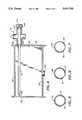
- FIG. 1is a top view of a plasma sterilizer of this invention.
- FIG. 2is a front view of the plasma sterilizer embodiment of FIG. 1.
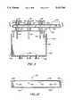
- FIG. 3is a cross-sectional view of the plasma sterilizer embodiment of FIG. 1 and FIG. 2, taken along the line 3--3 in FIG. 2.
- FIG. 4is a cross-sectional view of the plasma sterilizer embodiment of FIG. 3, taken along the line 4--4.
- FIG. 5is a cross-sectional view of tube 54 taken along line 5--5 in FIG. 3.
- FIG. 6is a cross-sectional view of tube 58 taken along line 6--6 in FIG. 3.
- FIG. 7is a cross-sectional view of tube 56 taken along line 7--7 in FIG. 3.
- FIG. 8is a partial cross-sectional view of the plasma generator tube and assembly of the embodiment of FIG. 1.
- FIG. 9is a partial, fragmentary, cross-sectional detail view of the plasma generator tube of the plasma generator shown in FIG. 8.
- FIG. 10is a cross-sectional view of the waveguide of the embodiment of FIG. 1, taken along the line 10--10 in FIG. 3.
- FIG. 11is a side cross-sectional view of an alternate single waveguide embodiment of the plasma sterilizer of this invention.
- FIG. 12is a cross-sectional view of the waveguide of the embodiment of FIG. 11, taken along the line 12--12.
- FIG. 13is a side cross-sectional view of a multiple magnetron embodiment of this invention.
- FIG. 14is a front cross-sectional view of the multiple waveguide embodiment of the plasma sterilizer of this invention, taken along the line 14--14 of FIG. 13.
- FIG. 15is a partial cross-sectional view of the plasma generator tube and assembly of the embodiment of FIG. 13.
- the gas sterilizer and process of this inventionproduces a plasma from gas mixtures containing essentially oxidizing agents such as oxygen and/or reducing agents such as hydrogen, and optionally other carrier gases such as inert gases.
- gas mixturescontaining essentially oxidizing agents such as oxygen and/or reducing agents such as hydrogen, and optionally other carrier gases such as inert gases.
- the exhaust gas productsfully satisfy current environmental and worker safety concerns, the products of the plasma being almost entirely water vapor, carbon dioxide and non-toxic gases normally found in the atmosphere.
- sterilizationconnotes a process by which all viable forms of microorganisms are destroyed or removed from an object. Since microorganisms die according to first order chemical kinetics, it is customary to define sterility in terms of "probability of survivors". The practical goal of a sterilization process is therefore measured as a probability (e.g., 10 -3 , 10 -6 , 10 -12 the probability indicating the lethal effect of a particular sterilizing dose or regimen. It is usual to assume increased time of exposure to a set of sterilizing conditions will decrease the probability of survivors accordingly.
- plasmaas used herein is defined to include any portion of the gas or vapors which contain electrons, ions, free radicals, dissociated and/or excited atoms or molecules produced as a result of the applied electric or electromagnetic field including any accompanying radiation which might be produced.
- the electromagnetic fieldcan cover a broad frequency range, and can be produced by a magnetron, klystron or RF coil.
- a magnetronas the electromagnetic field source, and the use of all other suitable sources of the electromagnetic field required for plasma production are intended to be included in this invention, including without limitation, magnetrons, klystron tubes, RF coils, and the like.
- FIG.1is a top view and FIG. 2 is a front view of a single waveguide plasma sterilizer embodiment of this invention.
- the plasma sterilizerhas a plasma generator 2 and a sterilizing chamber 4.
- the plasma generator 2comprises an electromagnetic field generator such as a magnetron 6 and a waveguide 8 which directs the electromagnetic field.
- the plasma source gasesare directed into plasma generating and delivering tubes 10, 12, and 14 by feeder tubes from gas delivery tubes 16, 18 and 20 leading from the control valve complex 22. Individual gases are fed from the pressured gas sources (not shown) by inlet lines 24, 25 and 26.
- the operation of the control valves in valve complex 22is controlled by the central processing unit (CPU) 28 by standard procedures.
- the control valves and CPUcan be any of the conventional, standard devices used for gas flow control in plasma generating equipment.
- the sterilizing chamber 4comprises top plate 30, side plates 32 and 34, bottom plate 36, back plate 37 and front sealing door 38 through which articles or materials to be sterilized are placed in the chamber.
- the platesare attached together in a sealed relationship to form a vacuum chamber, such as by welding.
- the door 38is secured in a sealed relationship with the sterilizing chamber. It is hinged at the top, side or bottom with conventional hinge pins (structure not shown) to swing against abutting surfaces and an O-ring seal 40 (FIG. 3) of the side, top and bottom plates, where the pressure difference between the internal chamber vacuum pressure and the surrounding atmospheric pressure holds it tightly in place.
- the plates and doorcan be made of any material having the strength required to withstand the external atmospheric pressure when the chamber is evacuated. Stainless steel or aluminum plates and door are preferred.
- the internal surface material of the chamberis critical and greatly affects the number of killing species available in the chamber.
- a suitable materialis pure (98%) aluminum which can be applied either as a liner or as a flame-sprayed coating on all internal walls of the stainless steel chamber.
- An alternate materialis nickel.
- An optimum materialis an inert polymer such as polytetra-fluoroethylene (TEFLON).
- the gasesare exhausted from the sterilizing chamber through exhaust outlet port 42 to a conventional vacuum pump system (not shown).
- FIG. 3is a top cross-sectional view of the plasma sterilizer embodiment of FIG. 1 and FIG. 2, taken along the line 3--3 in FIG. 2.
- FIG. 4is a side cross-sectional view of the plasma sterilizer embodiment of FIG. 1 and FIG. 3, taken along the line 4--4 in FIG. 3.
- Each of the plasma generators 10, 12 and 14comprise an inlet cap 44 with gas inlet ports 46, 48 and 50 leading to a respective gas generator tube 51, 52 or 53 leading through the waveguide 8.
- the gasesare energized and convert in tubes 51, 52 and 53 to a plasma.
- the gas generator tubedirects the plasma flow into the gas distribution tubes 54, 56 and 58 from which the plasma is fed into the sterilizing chamber 60.
- the gas generator tubesare enclosed in tubular metal cooling tubes 62 and 64.
- the caps 44 and the cooling tubes 62 and 64are preferably provided with grooves or cooling fins (not shown) in a conventional manner to increase their efficiency in removing heat from gas generator tubes.
- the distal end of tubes 51, 52 and 53have increased thickness and forms a smooth surfaced venturi restriction 96 of reduced cross-sectional area.
- Cap 98 positioned on the proximal end of plasma distribution tube 56has a preselected restrictive opening 99 of further reduced cross-sectional area.
- the diameter of the restrictive opening 99is selected to maintain a back pressure of from 0.1 to 150 torr and preferably from 1 to 40 torr in the plasma generating zone, with a vacuum chamber pressure in the range of from 0.01 to 100 torr and preferably from 0.1 to 15 torr.
- This pressureprovides optimum energy transfer from the electromagnetic field to the gases with gas mixtures containing oxygen; argon, helium and/or nitrogen; and/or hydrogen and is a major factor for the production of a high yield of plasma at a minimum temperature and with the minimum power requirement achieved with the device of this invention.
- the distal ends of the gas distribution tubes 54, 56 and 58are supported by spring-biased end supports 66 mounted on sideplate 32.
- the door 38is held in sealing engagement by atmospheric pressure against the O-ring seal 40 mounted in the flange 41 extending from the side plates 32 and 34, and the top and bottom plates 30 and 36 (not shown).
- additional conventional closure clamps or latchescan be used to insure closure of the door before chamber evacuation is initiated.
- FIG. 5, FIG. 6 and FIG. 7are cross-sectional views of gas distribution tubes 54, 58 and 56, respectively, showing angular positions of the gas distribution outlet ports.
- the outlet portsare positioned to provide plasma flow to all lower portions of the sterilizing chamber 60 where articles to be sterilized are placed.
- Tube 54 shown in FIG. 5is placed adjacent back plate 37 and directs plasma gases downward and toward the lower center of the chamber through outlet ports 70 and 72, respectively.
- Tube 58 shown in FIG. 6is placed adjacent the door 38 and directs plasma gases downward and toward the lower center of the chamber through outlet ports 74 and 76, respectively.
- Tube 56 shown in FIG. 7is placed in the central portion of the chamber 60 and directs plasma gases laterally downward through outlet ports 78 and 80.
- each tubecan have more than one angular set of outlet ports, each having different angles, along the length of the tube, as desired.
- the choice of outlet port angles and locationsshould be selected in view of how the articles to be sterilized are to be placed in the chamber and the type of article to be sterilized.
- the plasmais directed through a change of direction preferably at least 90°, before discharging it into the sterilizing chamber. This prevents direct impingement of hot plasma onto the articles being sterilized, greatly reducing the oxidation of sensitive packaging materials by the activated oxygen atoms in the plasma. Allowing the plasma gases to impinge instead on any relatively cool part of the distribution tubes or sterilizing chamber will have the effect of cooling the gases, which will in turn keep the articles and packaging cool, which will reduce oxidation.
- FIG. 8is a partial top cross-sectional detail fragmentary view of plasma generator tube 12 of FIG. 3, and FIG. 9 is a more detailed view of the plasma generator tube outlet assembly shown in FIG. 3.
- the gas inlet ports 46 and 50 in the gas inlet cap 44are connected by passageways 82 and 84 to the gas inlet passageway 86 leading from inlet port 48.
- the gases fed to the inlet portsare mixed in the passageway 86.
- the gas mixturepasses into the proximal end of the tube 52 and through the excitation zone 87 within the waveguide 8 where the plasma is formed.
- the proximal end of the plasma generator tube 52is supported on cylindrical projection 88.
- O-ring 90 or another type of sealforms a gas-tight seal therewith, thereby maintaining a reduced pressure in the tube 52 and preventing leakage of atmospheric gas into the system.
- an optional plasma starter ionizeris shown.
- the tip 81is connected by an insulated conduit 83 (shown schematically) to a power supply 85 which can be powered with a standard 115 V AC power source.
- a ground conduit 89 from the power supplyconnects to the gas inlet cap 44.
- the electric fieldionizes a portion of the gas molecules flowing from opening 48 through passageway 86, the ionized gases quickly supporting a plasma as the gases pass through the zone 87.
- the ionizercan be placed in any of the inlet gas passageways of any of the embodiments of this invention.
- the outer surface 92 of the distal end of the plasma generator tube 52is tapered inward and is sealed by O-ring 94 or other form of seal with the backplate 37.
- the distal end of tube 52has increased thickness and forms a smooth surfaced venturi restriction 96 of reduced cross-sectional area.
- Cap 98 positioned on the proximal end of plasma distribution tube 56has a preselected restrictive opening 99 of further reduced cross-sectional area.
- the diameter of the restrictive opening 99is selected to maintain a back pressure of from 0.1 to 150 torr, preferably from 1 to 40 torr in the plasma generating zone with a vacuum chamber pressure in the range of from 0.01 to 100 torr, preferably from 0.1 to 15 torr.
- This pressureprovides optimum energy consumption and plasma generation with gas mixtures containing oxygen; argon, helium and/or nitrogen; and/or hydrogen and is a major factor for the production of a high yield of plasma at a minimum temperature and with the minimum power requirement achieved with the device of this invention.
- FIG. 10is a cross-sectional view of the waveguide of the embodiment of FIG. 1, taken along the line 10--10 in FIG. 3.
- the waveguideis formed of top and bottom plates 100 and 102, side plates 104 and 106 (FIG. 3), and end plates 108 and 110, welded or bolted together.
- a single magnetron rod 112is placed in the end of the waveguide 8.
- the plasma generating tubes 51, 52 and 53are positioned in the waveguide 8. The positions of the plasma generating tubes are selected to provide maximum conversion of the electromagnetic field energy to plasma.
- Tube 53is positioned in a zone to interact with a third of the field and not with zones of the field which will interact with tubes 51 and 52.
- Tube 52is positioned in a zone to interact with a third of the field (half of the remaining field) and not with the field zone which will interact with tube 51.
- Tube 51is positioned to interact maximally with the remainder of the field.
- FIG. 10Three tubes have been shown in FIG. 10 by way of example and not by way of limitation. Any number, odd or even, of tubes can be used up until the total power of the electromagnetic field is absorbed.
- FIG. 11is a front cross-sectional view of an alternate single wave guide embodiment of the plasma sterilizer of this invention.
- Three plasma generating units 120are positioned above the sterilizing chamber 122 defined by upper plate 124, lower plate 126, back plate 128, back plate 130 and side plates 128 and 132.
- the door plate(not shown) can be mounted to the front of the chamber as described above with respect to FIG. 2 and FIG. 3 and forms a sealed engagement with the front edges of the chamber walls.
- the gasesare exhausted from the chamber through exhaust ports 136 in the floor plate 126.
- the plasma generatorscomprise an inlet port for mixed gases 138 leading to the plasma generating tubes 139, 140 and 141 positioned in the waveguide 142 where the gases are energized and converted to a plasma.
- the plasmais directed by the plasma distributors 144 to the interior of the sterilizing chamber 122.
- Each plasma distributor 144can have a T-configuration described below in detail with respect to the embodiment of FIG. 14.
- the distributorcan have any shape and size which distributes the plasma gases uniformly throughout the sterilizing chamber.
- the plasma generating source in this embodimentis a magnetron 146 positioned at the end of the waveguide 142.
- FIG. 12is a cross-sectional view of the waveguide of embodiment of FIG. 11, taken along line 12--12 in FIG. 11.
- the waveguideis formed of top and bottom plates 150 and 152 (FIG. 11), side plates 154 and 156, and end plates 158 and 160, welded or bolted together.
- a single magnetron rod 162is placed in the end of the waveguide 142.
- the plasma generating tubes 139, 140 and 141are positioned in the waveguide 142. The positions of the plasma generating tubes are selected to provide maximum conversion of the electromagnetic field energy to plasma.
- Tube 141is positioned in a zone to interact with a third of the field and not with zones of the field which will interact with tubes 140 and 139.
- Tube 140is positioned in a zone to interact with a third of the field (half of the remaining field) and not with the field zone which will interact with tube 139.
- Tube 139is positioned to interact maximally with the remainder of the field.
- a single magnetroncan be used to generate plasma with a plurality of gas generating tubes.
- the precise placement of the tubes which will accomplish this resultwill depend upon the dimensions of the wave guide and the wavelength or frequency of the energizing wave.
- Three tubeshave been shown in FIG. 12 by way of example and not by way of limitation. Any number, odd or even, of tubes can be used up until the total power of the electromagnetic field is absorbed.
- FIG. 13is a front cross-sectional view of a multiple magnetron embodiment of this invention
- FIG. 14is a side cross-sectional view taken along the line 14--14 in FIG. 13.
- Three plasma generators 208 of this embodimentare positioned above the sterilizing chamber cavity 229, each producing a plasma generated from a gas mixture of oxygen; argon, helium and/or nitrogen; and/or hydrogen introduced through inlets 210 to a plasma generating tube 230 positioned in the respective waveguides 202.
- the plasma producedis fed by plasma generating tubes 230 through respective gas distributors 211, 212 and 213 into the sterilizing chamber 229.
- the distributor tubescan have any length and configuration required for distributing the plasma gases uniformly throughout the sterilizing chamber. Distribution tubes made of non-fragile materials are particularly advantageous. Suitable non-fragile tubes can be made of oxidation resistant metals such as stainless steel. An optimum material is an inert polymer such as polytetra-fluoroethylene (TEFLON).
- the sterilizing chamber 229is constructed from metal plates welded to form a gas-tight construction which is able to withstand external pressures when the chamber is evacuated.
- the constructioncomprises top plate 214, bottom plate 216, back plate 218, side plates 217 and 219. Exhaust ports 222 are mounted in the bottom plate 216.
- the door 224is supported by conventional pin hinges or the like (not shown) mounted on the side, top or bottom of the chamber walls as described above with respect to the embodiment of FIG. 1. Referring also to FIG. 14, the door 224 is held in sealing engagement by atmospheric pressure against the O-ring seal 225 mounted in the flange 227 extending from the side plates 217 and 219, and the top and bottom plates 214 and 216 (not shown).
- additional conventional closure clamp or latch devicescan be used to insure closure of the door before chamber evacuation is initiated.
- the oxygen; argon, helium and/or nitrogen; and/or hydrogen gasesare fed by inlet lines 228, 231 and 232 to the control valve and gas mixing unit 233 controlled by CPU 234.
- the gas mixtureis fed to the inlet port 210 by conduit 235 and then to the plasma generating tube 230 where it is energized to form a gas plasma.
- the control valves and CPUcan be any of the conventional, standard devices used for gas flow control in plasma generating equipment.
- the waveguide 202guides the electromagnetic waves generated by the magnetron 206 in a pattern which concentrates the electromagnetic energy in a zone in which the plasma generator tube 230 is positioned.
- a tuning rod 240can be vertically positioned to tune the electromagnetic waves to provide optimum plasma generation.
- the gas plasmais then fed to the gas distributor 212 and its Y-or T-distribution section 241.
- the horizontal distributorshave angular outlet ports positioned and with angular displacement as described with respect to the preferred embodiment of FIG. 5, FIG. 6 and FIG. 7.
- the plasmais directed through a change of direction of 90° twice before it is discharged into the sterilizing chamber. This prevents direct impingement of hot nascent plasma onto the articles being sterilized, greatly reducing the oxidation of sensitive packaging materials by the activated oxygen atoms in the plasma.
- FIG. 15is a fragmentary, cross-sectional view of the plasma generating tube of the plasma generator shown in FIG. 14, showing details of the tube construction and its connection with the gas distributor tube.
- the tube 230is held in a sealed engagement with the heat radiating cap 250 by O-ring 252 or a similar seal.
- the lower distal end of the tubeis also held in a sealed engagement with the lower heat radiator sleeve 254 by an O-ring 256.
- the proximal end of the distribution tube 212extends into the distal end of tube 230 and is held in a sealed relationship with the lower heat radiator sleeve by an O-ring 258.
- Cap 260is positioned on the proximal end of plasma distribution tube 212 and has a preselected restrictive opening 262 of further reduced cross-sectional area. As described with respect to the embodiment shown in FIG. 9, the restriction is a critical aspect of the invention, creating a pressure difference between the low pressure plasma generating zone and the pressure in the distribution tube and sterilizing chamber.
- the diameter of the restrictive opening 262is selected to maintain a back pressure of from 0.1 to 150 torr, preferably from 1 to 40 torr in the plasma generating zone with a vacuum chamber pressure in the range of from 0.01 to 100 torr, preferably from 0.1 to 15 torr.
- This pressureprovides optimum energy consumption and plasma generation with gas mixtures containing oxygen; argon, helium and/or nitrogen; and/or hydrogen and is a major factor for the production of a high yield of plasma at a minimum temperature and with the minimum power requirement achieved with the device of this invention.
- the embodiments of this inventionhave been presented with three plasma generating units.
- the number of generating unitsis not critical, being selected to provide a good plasma distribution in the particular sterilizing chamber used. Any desired number of plasma generators can be used with each sterilizing chamber and are intended to be included within the scope of this invention. It will be also be readily apparent that any number of gas plasma tubes can be positioned to interact with the electromagnetic field generated from a single magnetron with this waveguide configuration, and that other waveguide configurations can be used to achieve this effect.
- the preferred plasma generating tubes and plasma distributing tubesare made of quartz. However, any other materials with the necessary physical, chemical and electrical properties for plasma generation in an electromagnetic field can be used for the plasma generating tubes.
- conduits and tubing used for transport of plasma from the plasma generator to the sterilizing chambercan be any solid material which has the requisite shape and strength and which is resistant to chemical action and degradation by the plasma gases.
- Suitable transport conduit materialsinclude quartz and other plasma corrosion resistant glasses; stainless steel and other oxidation resistant metals; oxidation resistant plastics such as fluorocarbon polymers, e.g. TEFLON and the like, and siloxane polymers.
- the plasmais directed through a change of direction, preferably at least 90° before discharging it into the sterilizing chamber. This prevents direct impingement of hot plasma onto the articles being sterilized.
- the gas distributorsalso allow ions to recombine by collisions with their surfaces and allow the UV radiation to dissipate.
- the apparatuscan be used to generate a sterilizing plasma from a mixture of oxygen; argon, helium, and/or nitrogen; and hydrogen, or with a mixture of air and hydrogen, supplemented by oxygen or nitrogen to give the desired ratios.
- the sterilizationis carried out at a pressure of from 0.01 to 15 torr and preferably from 0.1 to 15 torr. Sterilization may be carried out at higher pressures provided steps are taken to ensure uniformity of gas flows and temperature throughout the chamber.
- the temperature in the sterilizing chamberis maintained below 80° C. and preferably from 38° to 60° C. for articles that can not tolerate high temperatures. Elevated temperatures may preferably be used with articles capable of withstanding them.
- the apparatus disclosed hereinis capable of producing plasma having uncharged, highly reactive species.
- oxygen and hydrogenare energized by microwave radiation and form a plasma having an initial high concentration of ions and ultraviolet emissions. These are not allowed into the sterilization chamber as they tend to be very destructive to the article to be sterilized, or the packaging.
- the UV emissionsare localized in the plasma generating chamber and are attenuated by the restriction means and the plasma distribution means before they reach the sterilizing chamber.
- high energy ionshit the restriction means and the internal wall of the plasma distribution means, they recombine with free electrons to revert to uncharged, highly reactive free radicals, uncharged atoms and excited molecules.
- the plasma's downstream productsinclude high concentrations of highly reactive uncharged free radicals, uncharged atoms and excited molecules.
- a microwave sourceis used to generate the plasma. It is channeled by a waveguide to form a highly confined electromagnetic (EM) field zone. Little of that field can spread to the sterilizing chamber. Thus, production of high energy ions and UV is only possible in the field region of the plasma generating chamber and not outside of it. Also, there is no EM field to cause non-uniformity in the sterilizing chamber.
- the restriction meansapart from obstructing the passage of UV and ions as noted above, further helps to make plasma generation outside the plasma generating chamber less favorable. The restriction means maintains an optimal gas pressure in the plasma generating chamber for generating plasma. Once the gas exits via the restriction means, the pressure and the EM field drop to make generation impossible under normal conditions. Thus, UV and ions can only be generated in the plasma generating chamber; once outside, they are allowed to dissipate to form a downstream plasma including high concentrations of highly reactive uncharged free radicals, atoms and excited molecules.
- the method of this invention for plasma sterilizationcomprises exposing an article to be sterilized to a plasma generated from a gaseous mixture of argon, helium or nitrogen mixed with oxygen and/or hydrogen at temperatures of less than 60° C., a pressure of from 0.01 to 100 torr, preferably from 0.1 to 15 torr and a treatment time of at least 5, and preferably from 10 to 15 minutes.
- the gas mixtures from which the plasma is generatedcan contain from 1 to 21 (v/v) % oxygen and from 1 to 20 (v/v) % hydrogen, the balance being argon, helium and/or nitrogen and optional small quantities of inert gases.
- the gas mixtures producing plasmas for sterilizing packagespreferably contain from 1 to 10 (v/v) % oxygen and from 2 to 8 (v/v) % hydrogen, and optimally contain from 2 to 8 (v/v) % oxygen and from 3 to 7 (v/v) % hydrogen.
- Packagesare treated for at least 15 minutes and preferably from 1 to 5 hours.
- packaged goodsare sterilized by treatment for at least 15 minutes and preferably from 1 to 5 hours with plasma generated from a gas mixture containing from 1 to 10 (v/v) % hydrogen and from 90 to 99 (v/v) % argon, helium and/or nitrogen, with little or no amounts of oxygen being present, the optimum mixture comprising 5 (v/v) % hydrogen and about 95 (v/v) % argon.
- Objects which are resistant to oxidationsuch as metallic surgical instruments can be sterilized by treatment for at least 1 minute and preferably for at least 5 minutes with plasma generated from a gas mixture containing from 10 to 40 (v/v) % oxygen; from 60 to 90 (v/v) % argon, helium and/or nitrogen; and optional amounts of hydrogen and/or inert gases at a pressure of from 0.01 to 100 torr, preferably from 0.1 to 15 torr.
- the plasmacan be generated from air (21 v/v % oxygen, 78 v/v % nitrogen, etc.), for example.
- the operating temperature of the present processis determined by the characteristics of the articles being sterilized, not by temperature limitations of the sterilization process. Many medical articles to be sterilized will not withstand temperature over 60° C. while other articles such as metallic surgical instruments are more efficiently sterilized at higher temperatures.
- pressure limitations givenare examples illustrative of the preferred embodiments. Different pressure limits are contemplated for other plasma sterilizers having different dimensions and surface characteristics.
- a processing time of from 5 to 10 minutesis usually sufficient to sterilize most articles. Clean articles packaged in envelopes or other shapes having porous surfaces allowing easy penetration of the plasma are usually completely sterilized within 60 minutes.
- the articles to be sterilizedare placed in the sterilizing chamber, supported by conventional fixtures which permit the plasma gas products to reach all surfaces of the articles.
- the chamberis closed, the sterilizing chamber is evacuated, plasma generation is begun, and the plasma gas products are directed into and through the sterilizing chamber.
- the plasma componentshave a short life, and quickly decay to form water vapor (gas), carbon dioxide, and other non-toxic components usually found in air. These are fully acceptable as residues or as exhaust gas components.
Landscapes
- Physics & Mathematics (AREA)
- Engineering & Computer Science (AREA)
- Plasma & Fusion (AREA)
- Health & Medical Sciences (AREA)
- Epidemiology (AREA)
- Spectroscopy & Molecular Physics (AREA)
- Electromagnetism (AREA)
- Life Sciences & Earth Sciences (AREA)
- Animal Behavior & Ethology (AREA)
- General Health & Medical Sciences (AREA)
- Public Health (AREA)
- Veterinary Medicine (AREA)
- Apparatus For Disinfection Or Sterilisation (AREA)
- Manufacture And Refinement Of Metals (AREA)
Abstract
Description
Claims (20)
Priority Applications (7)
| Application Number | Priority Date | Filing Date | Title |
|---|---|---|---|
| US07/885,299US5413760A (en) | 1989-03-08 | 1992-05-18 | Plasma sterilizer and method |
| CA002096368ACA2096368C (en) | 1992-05-18 | 1993-05-17 | Plasma sterilizer and method |
| JP5139514AJPH06169975A (en) | 1992-05-18 | 1993-05-18 | Plasma sterilizer and sterilization method |
| DE9321029UDE9321029U1 (en) | 1992-05-18 | 1993-05-18 | Plasma sterilizer |
| AU38666/93AAU662869B2 (en) | 1992-05-18 | 1993-05-18 | Plasma sterilizer and method |
| EP93108048AEP0570898A1 (en) | 1992-05-18 | 1993-05-18 | Plasma sterilizer and method |
| IT95MI000589UITMI950589U1 (en) | 1992-05-18 | 1995-08-10 | PLASMA STERILIZATION EQUIPMENT |
Applications Claiming Priority (4)
| Application Number | Priority Date | Filing Date | Title |
|---|---|---|---|
| US32148389A | 1989-03-08 | 1989-03-08 | |
| US47560290A | 1990-02-06 | 1990-02-06 | |
| US07/576,292US5115166A (en) | 1989-03-08 | 1990-08-31 | Plasma sterilizer and method |
| US07/885,299US5413760A (en) | 1989-03-08 | 1992-05-18 | Plasma sterilizer and method |
Related Parent Applications (2)
| Application Number | Title | Priority Date | Filing Date |
|---|---|---|---|
| US47560290AContinuation-In-Part | 1989-03-08 | 1990-02-06 | |
| US07/576,292Continuation-In-PartUS5115166A (en) | 1989-03-08 | 1990-08-31 | Plasma sterilizer and method |
Publications (1)
| Publication Number | Publication Date |
|---|---|
| US5413760Atrue US5413760A (en) | 1995-05-09 |
Family
ID=25386592
Family Applications (1)
| Application Number | Title | Priority Date | Filing Date |
|---|---|---|---|
| US07/885,299Expired - LifetimeUS5413760A (en) | 1989-03-08 | 1992-05-18 | Plasma sterilizer and method |
Country Status (6)
| Country | Link |
|---|---|
| US (1) | US5413760A (en) |
| EP (1) | EP0570898A1 (en) |
| JP (1) | JPH06169975A (en) |
| AU (1) | AU662869B2 (en) |
| CA (1) | CA2096368C (en) |
| IT (1) | ITMI950589U1 (en) |
Cited By (34)
| Publication number | Priority date | Publication date | Assignee | Title |
|---|---|---|---|---|
| US5980825A (en)* | 1996-04-04 | 1999-11-09 | Johnson & Johnson Medical, Inc. | Method of sterilization using pretreatment with hydrogen peroxide |
| US6113851A (en)* | 1996-03-01 | 2000-09-05 | Phygen | Apparatus and process for dry sterilization of medical and dental devices and materials |
| US20010031234A1 (en)* | 1999-12-15 | 2001-10-18 | Christos Christodoulatos | Segmented electrode capillary discharge, non-thermal plasma apparatus and process for promoting chemical reactions |
| US20020022246A1 (en)* | 1997-09-19 | 2002-02-21 | Szu-Min Lin | Container monitoring system |
| US6495100B1 (en) | 1996-04-04 | 2002-12-17 | Ethicon, Inc. | Method for sterilizing devices in a container |
| US20030012689A1 (en)* | 2001-07-09 | 2003-01-16 | Pharmaceutical Systems, Inc. | Apparatus for testing sterilization methods and materials |
| US20030031610A1 (en)* | 1999-12-15 | 2003-02-13 | Plasmasol Corporation | Electrode discharge, non-thermal plasma device (reactor) for the pre-treatment of combustion air |
| US20030052096A1 (en)* | 2001-07-02 | 2003-03-20 | Plasmasol, Llc | Novel electrode for use with atmospheric pressure plasma emitter apparatus and method for using the same |
| US20030051993A1 (en)* | 1999-12-15 | 2003-03-20 | Plasmasol Corporation | Chemical processing using non-thermal discharge plasma |
| US20030106788A1 (en)* | 2001-11-02 | 2003-06-12 | Sergei Babko-Malyi | Non-thermal plasma slit discharge apparatus |
| US20030132100A1 (en)* | 1999-12-15 | 2003-07-17 | Plasmasol Corporation | In situ sterilization and decontamination system using a non-thermal plasma discharge |
| US20040050684A1 (en)* | 2001-11-02 | 2004-03-18 | Plasmasol Corporation | System and method for injection of an organic based reagent into weakly ionized gas to generate chemically active species |
| US20040062692A1 (en)* | 2002-09-30 | 2004-04-01 | Szu-Min Lin | Sterilization container kit |
| US6772776B2 (en) | 2001-09-18 | 2004-08-10 | Euv Llc | Apparatus for in situ cleaning of carbon contaminated surfaces |
| US20040170527A1 (en)* | 1996-04-04 | 2004-09-02 | Jacobs Paul T. | Apparatus and process for concentrating a liquid sterilant and sterilizing articles therewith |
| EP1520877A1 (en) | 2003-09-30 | 2005-04-06 | Depuy Products, Inc. | Medical implant or medical implant part with ultrahigh molecular weight polyethylene and at least one hydrophilic polymer |
| US20050196315A1 (en)* | 2004-01-22 | 2005-09-08 | Plasmasol Corporation | Modular sterilization system |
| US20050205410A1 (en)* | 2004-01-22 | 2005-09-22 | Plasmasol Corporation | Capillary-in-ring electrode gas discharge generator for producing a weakly ionized gas and method for using the same |
| US6955794B2 (en) | 1999-12-15 | 2005-10-18 | Plasmasol Corporation | Slot discharge non-thermal plasma apparatus and process for promoting chemical reaction |
| EP1642595A1 (en) | 2004-09-30 | 2006-04-05 | DePuy Products, Inc. | Hydrogel composition comprising crosslinked polyethylene oxide and methods for production |
| EP1676875A1 (en) | 2004-12-23 | 2006-07-05 | DePuy Products, Inc. | Polymer composition comprising cross-linked polyethylene and methods for making the same |
| US7094322B1 (en) | 1999-12-15 | 2006-08-22 | Plasmasol Corporation Wall Township | Use of self-sustained atmospheric pressure plasma for the scattering and absorption of electromagnetic radiation |
| US20070048176A1 (en)* | 2005-08-31 | 2007-03-01 | Plasmasol Corporation | Sterilizing and recharging apparatus for batteries, battery packs and battery powered devices |
| US20080033573A1 (en)* | 2003-09-19 | 2008-02-07 | Depuy Products, Inc. | Medical implant or medical implant part comprising porous uhmwpe and process for producing the same |
| US20080044553A1 (en)* | 2006-08-15 | 2008-02-21 | Abigail Freeman | Sterilization methods for medical devices |
| EP2095831A1 (en) | 2008-02-28 | 2009-09-02 | DePuy Products, Inc. | Hydrogel Composition |
| US20100155219A1 (en)* | 2007-03-15 | 2010-06-24 | Norbert Auner | Plasma-enhanced synthesis |
| WO2012028623A1 (en) | 2010-08-31 | 2012-03-08 | INSERM (Institut National de la Santé et de la Recherche Médicale) | Crosslinked polysaccharide beads and their biomedical uses |
| WO2012028620A1 (en) | 2010-08-31 | 2012-03-08 | INSERM (Institut National de la Santé et de la Recherche Médicale) | Porous polysaccharide scaffold comprising nano-hydroxyapatite and use for bone formation |
| US20120093686A1 (en)* | 2009-11-25 | 2012-04-19 | Kirsch Wolff M | Chitosan-based hemostatic textile |
| US20130136530A1 (en)* | 2011-07-01 | 2013-05-30 | Atg R&D Ltd | Clamp Ring |
| WO2013124444A1 (en) | 2012-02-24 | 2013-08-29 | INSERM (Institut National de la Santé et de la Recherche Médicale) | Crosslinked polysaccharide beads comprising an imaging agent |
| US9259357B2 (en) | 2014-04-16 | 2016-02-16 | Loma Linda University | Composition, preparation, and use of chitosan shards for biomedical applications |
| US9364588B2 (en) | 2014-02-04 | 2016-06-14 | Abbott Cardiovascular Systems Inc. | Drug delivery scaffold or stent with a novolimus and lactide based coating such that novolimus has a minimum amount of bonding to the coating |
Families Citing this family (7)
| Publication number | Priority date | Publication date | Assignee | Title |
|---|---|---|---|---|
| US5472664A (en)* | 1989-03-08 | 1995-12-05 | Abtox, Inc. | Plasma gas mixture for sterilizer and method |
| US5650693A (en)* | 1989-03-08 | 1997-07-22 | Abtox, Inc. | Plasma sterilizer apparatus using a non-flammable mixture of hydrogen and oxygen |
| SE504204C2 (en)* | 1994-12-28 | 1996-12-09 | Rune Soeremark | Method and apparatus for treating fluids and using this fluid |
| US5603895B1 (en)* | 1995-06-06 | 1998-11-03 | Abtox Inc | Plasma water vapor sterilizer and method |
| US20040005261A1 (en)* | 2002-04-23 | 2004-01-08 | Jung-Suek Ko | Plasma sterilization apparatus |
| JP2006102004A (en)* | 2004-10-01 | 2006-04-20 | Adtec Plasma Technology Co Ltd | Low temperature dry sterilization method and apparatus |
| KR101419386B1 (en)* | 2012-05-18 | 2014-07-15 | 서울여자대학교 산학협력단 | A food sterilizing apparatus using non-thermal plasma generated by microwave and sterilizing method using the same |
Citations (38)
| Publication number | Priority date | Publication date | Assignee | Title |
|---|---|---|---|---|
| DE268396C (en)* | ||||
| US3383163A (en)* | 1964-01-24 | 1968-05-14 | Little Inc A | Treatment of surfaces |
| US3410776A (en)* | 1966-02-01 | 1968-11-12 | Lab For Electronics Inc | Gas reaction apparatus |
| US3428548A (en)* | 1966-09-27 | 1969-02-18 | Lab For Electronics Inc | Plasma reaction system for reacting a gas with a non-gaseous material |
| US3704096A (en)* | 1970-10-16 | 1972-11-28 | Pollution Control Ind Inc | Sterilizing package and method and means for sterilizing an article and thereafter checking its sterility |
| US3737608A (en)* | 1970-05-30 | 1973-06-05 | Tokyo Shibaura Electric Co | Method and apparatus for sterilizing the interior of a vessel containing a fluid with some void space allowed therein |
| US3851436A (en)* | 1971-12-13 | 1974-12-03 | Boeing Co | Sterilizing and packaging process utilizing gas plasma |
| US3948601A (en)* | 1972-12-11 | 1976-04-06 | The Boeing Company | Sterilizing process and apparatus utilizing gas plasma |
| US4065369A (en)* | 1975-07-18 | 1977-12-27 | Tokyo Shibaura Electric Co., Ltd. | Activated gas reaction apparatus & method |
| US4123663A (en)* | 1975-01-22 | 1978-10-31 | Tokyo Shibaura Electric Co., Ltd. | Gas-etching device |
| US4138306A (en)* | 1976-08-31 | 1979-02-06 | Tokyo Shibaura Electric Co., Ltd. | Apparatus for the treatment of semiconductors |
| US4151034A (en)* | 1976-12-22 | 1979-04-24 | Tokyo Shibaura Electric Co., Ltd. | Continuous gas plasma etching apparatus |
| US4160690A (en)* | 1977-03-31 | 1979-07-10 | Tokyo Shibaura Electric Co., Ltd. | Gas etching method and apparatus |
| US4169123A (en)* | 1975-12-11 | 1979-09-25 | Moore-Perk Corporation | Hydrogen peroxide vapor sterilization method |
| US4169124A (en)* | 1977-09-26 | 1979-09-25 | Moore-Perk Corporation | Cold gas sterilization process |
| US4207286A (en)* | 1978-03-16 | 1980-06-10 | Biophysics Research & Consulting Corporation | Seeded gas plasma sterilization method |
| US4230663A (en)* | 1979-07-10 | 1980-10-28 | Moore-Perk Corporation | Cold gas sterilization process using hydrogen peroxide at low concentrations |
| US4289728A (en)* | 1979-01-11 | 1981-09-15 | National Research Development Corp. | Improvements in methods of sterilization |
| US4321232A (en)* | 1980-03-25 | 1982-03-23 | Tegal Corporation | Package and sterilizing process for same |
| US4348357A (en)* | 1980-12-12 | 1982-09-07 | Motorola, Inc. | Plasma pressure pulse sterilization |
| US4366125A (en)* | 1979-11-27 | 1982-12-28 | Dai Nippon Insatsu Kabushiki Kaisha | Sterilization apparatus and process utilizing synergistic effect of combining hydrogen peroxide and ultra-violet-ray sterilization |
| JPS5887825A (en)* | 1981-11-20 | 1983-05-25 | Fujitsu Ltd | Microwave plasma processing equipment |
| JPS58103460A (en)* | 1981-12-12 | 1983-06-20 | 株式会社巴商会 | Plasma pasturization |
| JPS58162276A (en)* | 1982-03-18 | 1983-09-26 | Iwatani & Co | How to sterilize E. coli on food surfaces |
| US4437567A (en)* | 1982-01-27 | 1984-03-20 | The Kendall Company | Sterile package and method of making |
| EP0109352A1 (en)* | 1982-11-16 | 1984-05-23 | Kantonsspital St. Gallen | Method of sterilizing utensils, particularly those made from thermolabile materials |
| US4640782A (en)* | 1985-03-13 | 1987-02-03 | Ozo-Tek, Inc. | Method and apparatus for the generation and utilization of ozone and singlet oxygen |
| US4643876A (en)* | 1985-06-21 | 1987-02-17 | Surgikos, Inc. | Hydrogen peroxide plasma sterilization system |
| US4801427A (en)* | 1987-02-25 | 1989-01-31 | Adir Jacob | Process and apparatus for dry sterilization of medical devices and materials |
| US4818488A (en)* | 1987-02-25 | 1989-04-04 | Adir Jacob | Process and apparatus for dry sterilization of medical devices and materials |
| GB2214081A (en)* | 1988-01-19 | 1989-08-31 | Santasalo Sohlberg Ab Oy | Procedure and equipment for sterilizing or disinfecting objects |
| US4917586A (en)* | 1987-02-25 | 1990-04-17 | Adir Jacob | Process for dry sterilization of medical devices and materials |
| US4931261A (en)* | 1987-02-25 | 1990-06-05 | Adir Jacob | Apparatus for dry sterilization of medical devices and materials |
| US4943417A (en)* | 1987-02-25 | 1990-07-24 | Adir Jacob | Apparatus for dry sterilization of medical devices and materials |
| EP0387022A2 (en)* | 1989-03-08 | 1990-09-12 | Abtox, Inc. | Plasma sterilizer and method |
| US4976920A (en)* | 1987-07-14 | 1990-12-11 | Adir Jacob | Process for dry sterilization of medical devices and materials |
| EP0474137A2 (en)* | 1990-08-31 | 1992-03-11 | Abtox, Inc. | Plasma sterilizing process with pulsed antimicrobial agent treatment |
| GB2253144A (en)* | 1991-03-01 | 1992-09-02 | Atomic Energy Authority Uk | Sterilisation using activated charge-free gaseous medium |
- 1992
- 1992-05-18USUS07/885,299patent/US5413760A/ennot_activeExpired - Lifetime
- 1993
- 1993-05-17CACA002096368Apatent/CA2096368C/ennot_activeExpired - Fee Related
- 1993-05-18AUAU38666/93Apatent/AU662869B2/ennot_activeCeased
- 1993-05-18JPJP5139514Apatent/JPH06169975A/enactivePending
- 1993-05-18EPEP93108048Apatent/EP0570898A1/ennot_activeWithdrawn
- 1995
- 1995-08-10ITIT95MI000589Upatent/ITMI950589U1/enunknown
Patent Citations (41)
| Publication number | Priority date | Publication date | Assignee | Title |
|---|---|---|---|---|
| DE268396C (en)* | ||||
| US3383163A (en)* | 1964-01-24 | 1968-05-14 | Little Inc A | Treatment of surfaces |
| US3410776A (en)* | 1966-02-01 | 1968-11-12 | Lab For Electronics Inc | Gas reaction apparatus |
| US3428548A (en)* | 1966-09-27 | 1969-02-18 | Lab For Electronics Inc | Plasma reaction system for reacting a gas with a non-gaseous material |
| US3737608A (en)* | 1970-05-30 | 1973-06-05 | Tokyo Shibaura Electric Co | Method and apparatus for sterilizing the interior of a vessel containing a fluid with some void space allowed therein |
| US3704096A (en)* | 1970-10-16 | 1972-11-28 | Pollution Control Ind Inc | Sterilizing package and method and means for sterilizing an article and thereafter checking its sterility |
| US3851436A (en)* | 1971-12-13 | 1974-12-03 | Boeing Co | Sterilizing and packaging process utilizing gas plasma |
| US3948601A (en)* | 1972-12-11 | 1976-04-06 | The Boeing Company | Sterilizing process and apparatus utilizing gas plasma |
| US4123663A (en)* | 1975-01-22 | 1978-10-31 | Tokyo Shibaura Electric Co., Ltd. | Gas-etching device |
| US4065369A (en)* | 1975-07-18 | 1977-12-27 | Tokyo Shibaura Electric Co., Ltd. | Activated gas reaction apparatus & method |
| US4169123A (en)* | 1975-12-11 | 1979-09-25 | Moore-Perk Corporation | Hydrogen peroxide vapor sterilization method |
| US4138306A (en)* | 1976-08-31 | 1979-02-06 | Tokyo Shibaura Electric Co., Ltd. | Apparatus for the treatment of semiconductors |
| US4151034A (en)* | 1976-12-22 | 1979-04-24 | Tokyo Shibaura Electric Co., Ltd. | Continuous gas plasma etching apparatus |
| US4160690A (en)* | 1977-03-31 | 1979-07-10 | Tokyo Shibaura Electric Co., Ltd. | Gas etching method and apparatus |
| US4169124A (en)* | 1977-09-26 | 1979-09-25 | Moore-Perk Corporation | Cold gas sterilization process |
| US4207286A (en)* | 1978-03-16 | 1980-06-10 | Biophysics Research & Consulting Corporation | Seeded gas plasma sterilization method |
| US4289728A (en)* | 1979-01-11 | 1981-09-15 | National Research Development Corp. | Improvements in methods of sterilization |
| US4230663A (en)* | 1979-07-10 | 1980-10-28 | Moore-Perk Corporation | Cold gas sterilization process using hydrogen peroxide at low concentrations |
| US4366125A (en)* | 1979-11-27 | 1982-12-28 | Dai Nippon Insatsu Kabushiki Kaisha | Sterilization apparatus and process utilizing synergistic effect of combining hydrogen peroxide and ultra-violet-ray sterilization |
| US4321232A (en)* | 1980-03-25 | 1982-03-23 | Tegal Corporation | Package and sterilizing process for same |
| US4321232B1 (en)* | 1980-03-25 | 1997-12-09 | Abtox Inc | Package and sterilizing process for same |
| US4348357A (en)* | 1980-12-12 | 1982-09-07 | Motorola, Inc. | Plasma pressure pulse sterilization |
| JPS5887825A (en)* | 1981-11-20 | 1983-05-25 | Fujitsu Ltd | Microwave plasma processing equipment |
| JPS58103460A (en)* | 1981-12-12 | 1983-06-20 | 株式会社巴商会 | Plasma pasturization |
| US4437567A (en)* | 1982-01-27 | 1984-03-20 | The Kendall Company | Sterile package and method of making |
| JPS58162276A (en)* | 1982-03-18 | 1983-09-26 | Iwatani & Co | How to sterilize E. coli on food surfaces |
| EP0109352A1 (en)* | 1982-11-16 | 1984-05-23 | Kantonsspital St. Gallen | Method of sterilizing utensils, particularly those made from thermolabile materials |
| US4640782A (en)* | 1985-03-13 | 1987-02-03 | Ozo-Tek, Inc. | Method and apparatus for the generation and utilization of ozone and singlet oxygen |
| US4643876A (en)* | 1985-06-21 | 1987-02-17 | Surgikos, Inc. | Hydrogen peroxide plasma sterilization system |
| US4818488A (en)* | 1987-02-25 | 1989-04-04 | Adir Jacob | Process and apparatus for dry sterilization of medical devices and materials |
| US4898715A (en)* | 1987-02-25 | 1990-02-06 | Adir Jacob | Process and apparatus for dry sterilization of medical devices and materials |
| US4917586A (en)* | 1987-02-25 | 1990-04-17 | Adir Jacob | Process for dry sterilization of medical devices and materials |
| US4931261A (en)* | 1987-02-25 | 1990-06-05 | Adir Jacob | Apparatus for dry sterilization of medical devices and materials |
| US4943417A (en)* | 1987-02-25 | 1990-07-24 | Adir Jacob | Apparatus for dry sterilization of medical devices and materials |
| US4801427A (en)* | 1987-02-25 | 1989-01-31 | Adir Jacob | Process and apparatus for dry sterilization of medical devices and materials |
| US4976920A (en)* | 1987-07-14 | 1990-12-11 | Adir Jacob | Process for dry sterilization of medical devices and materials |
| GB2214081A (en)* | 1988-01-19 | 1989-08-31 | Santasalo Sohlberg Ab Oy | Procedure and equipment for sterilizing or disinfecting objects |
| EP0387022A2 (en)* | 1989-03-08 | 1990-09-12 | Abtox, Inc. | Plasma sterilizer and method |
| EP0474137A2 (en)* | 1990-08-31 | 1992-03-11 | Abtox, Inc. | Plasma sterilizing process with pulsed antimicrobial agent treatment |
| GB2253144A (en)* | 1991-03-01 | 1992-09-02 | Atomic Energy Authority Uk | Sterilisation using activated charge-free gaseous medium |
| WO1992015336A1 (en)* | 1991-03-01 | 1992-09-17 | United Kingdom Atomic Energy Authority | Gas sterilisation |
Non-Patent Citations (27)
| Title |
|---|
| A. Russell (Ed.), The Destruction of Bacterial Spores, New York: Academic Press (1982).* |
| Fraser et al., "Plasma Sterilization Technology for Spacecraft Applications", NASA-CR-146314 Final Report (Boeing Co.), Sep. 1975. |
| Fraser et al., Plasma Sterilization Technology for Spacecraft Applications , NASA CR 146314 Final Report (Boeing Co.), Sep. 1975.* |
| Hollahan et al., "Analytical Applications of Electrodelessly Discharged Gases" Chemical Instrumental, Journal of Chem. Education, 43:A401-A416, May 1966. |
| Hollahan et al., "Chem. Education Letters", Journal of Chem. Education 43:392-393., Jul. 1966. |
| Hollahan et al., "Research with Electrodelessly Discharged Gases," Chemical Instrument, 43:A497-A512, Jun. 1966. |
| Hollahan et al., "Techniques and Applications of Plasma Chemistry," v-v11, 229-253., 1974. |
| Hollahan et al., Analytical Applications of Electrodelessly Discharged Gases Chemical Instrumental, Journal of Chem. Education, 43:A401 A416, May 1966.* |
| Hollahan et al., Chem. Education Letters , Journal of Chem. Education 43:392 393., Jul. 1966.* |
| Hollahan et al., Research with Electrodelessly Discharged Gases, Chemical Instrument, 43:A497 A512, Jun. 1966.* |
| Hollahan et al., Techniques and Applications of Plasma Chemistry, v v11, 229 253., 1974.* |
| Leaper et al., "A Note on the Effect of Storage on the Chemical Resistance of Spores of Bacillus subtilis SA22 and Bacillus subtilis Glogigii B17," J. Applied Biology 64:183-186, 1988. |
| Leaper et al., "Comparison of the Resistance to Hydrogen Peroxide of Wet and Dry Spores of Bacillus subtilis SA222," J. Food Technology, 19:695-702, (1984). |
| Leaper et al., "Influence of Temperature on the Synergistic Sporicidal Effect of Peracetic Acid Plus Hydrogen Peroxide on Bacillus subtilis" SA22 (NCA) 72-52), Food Microbiology, 1:199-203, 1984. |
| Leaper et al., "Synergistic Killing of Spores of Bacillus subtilis by Peracetic Acid and Alcohol," J. Food Technology, 19:355-360, 1984. |
| Leaper et al., A Note on the Effect of Storage on the Chemical Resistance of Spores of Bacillus subtilis SA22 and Bacillus subtilis Glogigii B17, J. Applied Biology 64:183 186, 1988.* |
| Leaper et al., Comparison of the Resistance to Hydrogen Peroxide of Wet and Dry Spores of Bacillus subtilis SA222, J. Food Technology, 19:695 702, (1984).* |
| Leaper et al., Influence of Temperature on the Synergistic Sporicidal Effect of Peracetic Acid Plus Hydrogen Peroxide on Bacillus subtilis SA22 (NCA) 72 52), Food Microbiology, 1:199 203, 1984.* |
| Leaper et al., Synergistic Killing of Spores of Bacillus subtilis by Peracetic Acid and Alcohol, J. Food Technology, 19:355 360, 1984.* |
| Ross A. Caputo et al., "AbTox Plazlyte™ plasma sterilization", Cold Sterilization Beyond 1985: A Look At Atlernatives To Dec. 1988 EtO, Journal of health-care material management, vol. 10, No. 8, Sep. 1992. |
| Ross A. Caputo et al., "Validation Testing of a Gas Plasma Sterilization System", Medical Device and Diagnostic Industry, vol. 15, No. 1, pp. 132-138 (1993). |
| Ross A. Caputo et al., AbTox Plazlyte plasma sterilization , Cold Sterilization Beyond 1985: A Look At Atlernatives To Dec. 1988 EtO, Journal of health care material management, vol. 10, No. 8, Sep. 1992.* |
| Ross A. Caputo et al., Validation Testing of a Gas Plasma Sterilization System , Medical Device and Diagnostic Industry, vol. 15, No. 1, pp. 132 138 (1993).* |
| Ross Caputo et al., "Alternative Sterilization Technologies Come of Age," Medical Device and Diagnostic Industry, V. 14, No. 12, pp. 41-42 (1992). |
| Ross Caputo et al., Alternative Sterilization Technologies Come of Age, Medical Device and Diagnostic Industry, V. 14, No. 12, pp. 41 42 (1992).* |
| Rudder et al., "Remote Plasma-Enhanced Chemical-Vapor Deposition of Epitaxial Ge Films," J. Appl. Phys., 60(10):3519-3522., Nov. 1986. |
| Rudder et al., Remote Plasma Enhanced Chemical Vapor Deposition of Epitaxial Ge Films, J. Appl. Phys., 60(10):3519 3522., Nov. 1986.* |
Cited By (67)
| Publication number | Priority date | Publication date | Assignee | Title |
|---|---|---|---|---|
| US6113851A (en)* | 1996-03-01 | 2000-09-05 | Phygen | Apparatus and process for dry sterilization of medical and dental devices and materials |
| US6589481B1 (en) | 1996-04-04 | 2003-07-08 | Ethicon, Inc. | Apparatus and method to pretreat and sterilize a lumen device |
| US6132680A (en)* | 1996-04-04 | 2000-10-17 | Ethicon, Inc. | Method for sterilizing an interior of an article |
| US7179419B2 (en) | 1996-04-04 | 2007-02-20 | Johnson & Johnson Medical Div Ethicon, Inc. | Method for sterilizing devices in a container |
| US6495100B1 (en) | 1996-04-04 | 2002-12-17 | Ethicon, Inc. | Method for sterilizing devices in a container |
| US20070048177A1 (en)* | 1996-04-04 | 2007-03-01 | Szu-Min Lin | Method for sterilizing lumen devices |
| US20040170527A1 (en)* | 1996-04-04 | 2004-09-02 | Jacobs Paul T. | Apparatus and process for concentrating a liquid sterilant and sterilizing articles therewith |
| US5980825A (en)* | 1996-04-04 | 1999-11-09 | Johnson & Johnson Medical, Inc. | Method of sterilization using pretreatment with hydrogen peroxide |
| US20030206827A1 (en)* | 1996-04-04 | 2003-11-06 | Szu-Min Lin | Method for sterilizing devices in a container |
| US20020022246A1 (en)* | 1997-09-19 | 2002-02-21 | Szu-Min Lin | Container monitoring system |
| US6815206B2 (en) | 1997-09-19 | 2004-11-09 | Ethicon, Inc. | Container monitoring system |
| US20030031610A1 (en)* | 1999-12-15 | 2003-02-13 | Plasmasol Corporation | Electrode discharge, non-thermal plasma device (reactor) for the pre-treatment of combustion air |
| US6923890B2 (en) | 1999-12-15 | 2005-08-02 | Plasmasol Corporation | Chemical processing using non-thermal discharge plasma |
| US20030132100A1 (en)* | 1999-12-15 | 2003-07-17 | Plasmasol Corporation | In situ sterilization and decontamination system using a non-thermal plasma discharge |
| US7094322B1 (en) | 1999-12-15 | 2006-08-22 | Plasmasol Corporation Wall Township | Use of self-sustained atmospheric pressure plasma for the scattering and absorption of electromagnetic radiation |
| US7029636B2 (en) | 1999-12-15 | 2006-04-18 | Plasmasol Corporation | Electrode discharge, non-thermal plasma device (reactor) for the pre-treatment of combustion air |
| US20030051993A1 (en)* | 1999-12-15 | 2003-03-20 | Plasmasol Corporation | Chemical processing using non-thermal discharge plasma |
| US7192553B2 (en) | 1999-12-15 | 2007-03-20 | Plasmasol Corporation | In situ sterilization and decontamination system using a non-thermal plasma discharge |
| US6955794B2 (en) | 1999-12-15 | 2005-10-18 | Plasmasol Corporation | Slot discharge non-thermal plasma apparatus and process for promoting chemical reaction |
| US20010031234A1 (en)* | 1999-12-15 | 2001-10-18 | Christos Christodoulatos | Segmented electrode capillary discharge, non-thermal plasma apparatus and process for promoting chemical reactions |
| US6818193B2 (en) | 1999-12-15 | 2004-11-16 | Plasmasol Corporation | Segmented electrode capillary discharge, non-thermal plasma apparatus and process for promoting chemical reactions |
| US7273594B2 (en) | 1999-12-22 | 2007-09-25 | Johnson & Johnson Medical Div Of Ethicon, Inc. | Sterilization container with self-sealing closure |
| US20030072701A1 (en)* | 1999-12-22 | 2003-04-17 | Szu-Min Lin | Sterilization container with self-sealing closure |
| US20030138347A1 (en)* | 2000-12-21 | 2003-07-24 | Szu-Min Lin | Attachable container sterilization system |
| US20030052096A1 (en)* | 2001-07-02 | 2003-03-20 | Plasmasol, Llc | Novel electrode for use with atmospheric pressure plasma emitter apparatus and method for using the same |
| US7098420B2 (en) | 2001-07-02 | 2006-08-29 | Plasmasol Corporation | Electrode for use with atmospheric pressure plasma emitter apparatus and method for using the same |
| US7090808B2 (en) | 2001-07-09 | 2006-08-15 | Pharmaceutical Systems, Inc. | Apparatus for testing sterilization methods and materials |
| US20030012689A1 (en)* | 2001-07-09 | 2003-01-16 | Pharmaceutical Systems, Inc. | Apparatus for testing sterilization methods and materials |
| US20040211448A1 (en)* | 2001-09-18 | 2004-10-28 | Euv Llc | Apparatus for in-situ cleaning of carbon contaminated surfaces |
| US7147722B2 (en) | 2001-09-18 | 2006-12-12 | Euv Llc | Method for in-situ cleaning of carbon contaminated surfaces |
| US6772776B2 (en) | 2001-09-18 | 2004-08-10 | Euv Llc | Apparatus for in situ cleaning of carbon contaminated surfaces |
| US20040050684A1 (en)* | 2001-11-02 | 2004-03-18 | Plasmasol Corporation | System and method for injection of an organic based reagent into weakly ionized gas to generate chemically active species |
| US20030106788A1 (en)* | 2001-11-02 | 2003-06-12 | Sergei Babko-Malyi | Non-thermal plasma slit discharge apparatus |
| US20040062692A1 (en)* | 2002-09-30 | 2004-04-01 | Szu-Min Lin | Sterilization container kit |
| US7300637B2 (en) | 2002-09-30 | 2007-11-27 | Ethicon, Inc. | Sterilization container kit |
| US7781526B2 (en) | 2003-09-19 | 2010-08-24 | Depuy Products, Inc. | Medical implant or medical implant part comprising porous UHMWPE and process for producing the same |
| US20080033573A1 (en)* | 2003-09-19 | 2008-02-07 | Depuy Products, Inc. | Medical implant or medical implant part comprising porous uhmwpe and process for producing the same |
| US20100283184A1 (en)* | 2003-09-19 | 2010-11-11 | Depuy Products, Inc. | Process for producing medical implant or medical implant part comprising porous uhmwpe |
| US7923512B2 (en) | 2003-09-19 | 2011-04-12 | Depuy Products, Inc. | Process for producing medical implant or medical implant part comprising porous UHMWPE |
| US20080044676A1 (en)* | 2003-09-30 | 2008-02-21 | Depuy Products, Inc. | Method for producing medical implant or medical implant part |
| EP1520877A1 (en) | 2003-09-30 | 2005-04-06 | Depuy Products, Inc. | Medical implant or medical implant part with ultrahigh molecular weight polyethylene and at least one hydrophilic polymer |
| US7785508B2 (en) | 2003-09-30 | 2010-08-31 | Depuy Products, Inc. | Method for producing medical implant or medical implant part |
| US20050205410A1 (en)* | 2004-01-22 | 2005-09-22 | Plasmasol Corporation | Capillary-in-ring electrode gas discharge generator for producing a weakly ionized gas and method for using the same |
| US20050196315A1 (en)* | 2004-01-22 | 2005-09-08 | Plasmasol Corporation | Modular sterilization system |
| EP1642595A1 (en) | 2004-09-30 | 2006-04-05 | DePuy Products, Inc. | Hydrogel composition comprising crosslinked polyethylene oxide and methods for production |
| EP1994948A2 (en) | 2004-09-30 | 2008-11-26 | DePuy Products, Inc. | Method for producing hydrogel composition comprising crosslinked polyethylene oxide |
| EP2113530A1 (en) | 2004-12-23 | 2009-11-04 | DePuy Products, Inc. | Polymer composition comprising cross-linked polyethylene |
| EP1676875A1 (en) | 2004-12-23 | 2006-07-05 | DePuy Products, Inc. | Polymer composition comprising cross-linked polyethylene and methods for making the same |
| US20070048176A1 (en)* | 2005-08-31 | 2007-03-01 | Plasmasol Corporation | Sterilizing and recharging apparatus for batteries, battery packs and battery powered devices |
| US20110209442A1 (en)* | 2006-08-15 | 2011-09-01 | Abbott Cardiovascular Systems Inc. | Sterilization Methods For Medical Devices |
| US8747738B2 (en) | 2006-08-15 | 2014-06-10 | Abbott Cardiovascular Systems Inc. | Sterilization methods for medical devices |
| US20080044553A1 (en)* | 2006-08-15 | 2008-02-21 | Abigail Freeman | Sterilization methods for medical devices |
| US9682162B2 (en) | 2006-08-15 | 2017-06-20 | Abbott Cardiovascular Systems Inc. | Sterilization methods for medical devices |
| US20100155219A1 (en)* | 2007-03-15 | 2010-06-24 | Norbert Auner | Plasma-enhanced synthesis |
| EP2095831A1 (en) | 2008-02-28 | 2009-09-02 | DePuy Products, Inc. | Hydrogel Composition |
| US20120093686A1 (en)* | 2009-11-25 | 2012-04-19 | Kirsch Wolff M | Chitosan-based hemostatic textile |
| US9226988B2 (en)* | 2009-11-25 | 2016-01-05 | Loma Linda University Medical Center | Chitosan-based hemostatic textile |
| US20150086419A1 (en)* | 2009-11-25 | 2015-03-26 | Loma Linda University Medical Center | Chitosan-based hemostatic textile |
| US8623274B2 (en)* | 2009-11-25 | 2014-01-07 | Loma Linda University Medical Center | Chitosan-based hemostatic textile |
| WO2012028620A1 (en) | 2010-08-31 | 2012-03-08 | INSERM (Institut National de la Santé et de la Recherche Médicale) | Porous polysaccharide scaffold comprising nano-hydroxyapatite and use for bone formation |
| WO2012028623A1 (en) | 2010-08-31 | 2012-03-08 | INSERM (Institut National de la Santé et de la Recherche Médicale) | Crosslinked polysaccharide beads and their biomedical uses |
| US20130136530A1 (en)* | 2011-07-01 | 2013-05-30 | Atg R&D Ltd | Clamp Ring |
| US10541503B2 (en)* | 2011-07-01 | 2020-01-21 | Atg R&D | Clamp ring |
| WO2013124444A1 (en) | 2012-02-24 | 2013-08-29 | INSERM (Institut National de la Santé et de la Recherche Médicale) | Crosslinked polysaccharide beads comprising an imaging agent |
| US9364588B2 (en) | 2014-02-04 | 2016-06-14 | Abbott Cardiovascular Systems Inc. | Drug delivery scaffold or stent with a novolimus and lactide based coating such that novolimus has a minimum amount of bonding to the coating |
| US9259357B2 (en) | 2014-04-16 | 2016-02-16 | Loma Linda University | Composition, preparation, and use of chitosan shards for biomedical applications |
| US9414967B2 (en) | 2014-04-16 | 2016-08-16 | Loma Linda University | Composition, preparation, and use of chitosan shards for biomedical applications |
Also Published As
| Publication number | Publication date |
|---|---|
| ITMI950589U1 (en) | 1997-02-10 |
| AU662869B2 (en) | 1995-09-14 |
| ITMI950589V0 (en) | 1995-08-10 |
| CA2096368A1 (en) | 1993-11-19 |
| AU3866693A (en) | 1993-11-25 |
| CA2096368C (en) | 2004-03-30 |
| EP0570898A1 (en) | 1993-11-24 |
| JPH06169975A (en) | 1994-06-21 |
Similar Documents
| Publication | Publication Date | Title |
|---|---|---|
| US5413760A (en) | Plasma sterilizer and method | |
| US5115166A (en) | Plasma sterilizer and method | |
| US5413759A (en) | Plasma sterilizer and method | |
| US5186893A (en) | Plasma cycling sterilizing process | |
| US5288460A (en) | Plasma cycling sterilizing process | |
| US5178829A (en) | Flash sterilization with plasma | |
| US5645796A (en) | Process for plasma sterilizing with pulsed antimicrobial agent treatment | |
| US5325020A (en) | Circular waveguide plasma microwave sterilizer apparatus | |
| US5650693A (en) | Plasma sterilizer apparatus using a non-flammable mixture of hydrogen and oxygen | |
| US5244629A (en) | Plasma sterilizing process with pulsed antimicrobial agent pretreatment | |
| US5184046A (en) | Circular waveguide plasma microwave sterilizer apparatus | |
| US5084239A (en) | Plasma sterilizing process with pulsed antimicrobial agent treatment | |
| US5603895A (en) | Plasma water vapor sterilizer and method | |
| US5472664A (en) | Plasma gas mixture for sterilizer and method | |
| US5593649A (en) | Canister with plasma gas mixture for sterilizer | |
| EP0456135A2 (en) | Sterilizing with hydrogen peroxide and plasma | |
| US5376332A (en) | Plasma sterilizing with downstream oxygen addition | |
| EP0456134A2 (en) | Sterilizing with peracid and plasma | |
| CA2224118C (en) | Plasma water vapor sterilizer and method |
Legal Events
| Date | Code | Title | Description |
|---|---|---|---|
| AS | Assignment | Owner name:ABTOX, INC., CALIFORNIA Free format text:ASSIGNMENT OF ASSIGNORS INTEREST.;ASSIGNORS:CAMPBELL, BRYANT A.;MOULTON, KERN A.;REEL/FRAME:006480/0808 Effective date:19920721 | |
| AS | Assignment | Owner name:ABTOX, INC. A CORPORATION OF DELAWARE, ILLINOIS Free format text:MERGER;ASSIGNOR:ABTOX, INC. A CORPORATION OF CALIFORNIA;REEL/FRAME:007082/0405 Effective date:19921216 | |
| STCF | Information on status: patent grant | Free format text:PATENTED CASE | |
| AS | Assignment | Owner name:FIRST MIDWEST BANK, N.A., ILLINOIS Free format text:SECURITY INTEREST;ASSIGNOR:ABTOX, INC.;REEL/FRAME:007678/0643 Effective date:19950505 | |
| AS | Assignment | Owner name:ABTOX, INC., ILLINOIS Free format text:RELEASE OF SECURITY INTEREST RECORDED AT REEL/FRAME 7678/0643;ASSIGNOR:FIRST MIDWEST BANK, N.A.;REEL/FRAME:009103/0915 Effective date:19980327 | |
| AS | Assignment | Owner name:WILMINGTON TRUST COMPANY, DELAWARE Free format text:SECURITY AGREEMENT;ASSIGNOR:ABTOX, INC.;REEL/FRAME:009328/0942 Effective date:19980326 | |
| REMI | Maintenance fee reminder mailed | ||
| FPAY | Fee payment | Year of fee payment:4 | |
| SULP | Surcharge for late payment | ||
| AS | Assignment | Owner name:DEPUY ORTHOPAEDICS, INC., INDIANA Free format text:ASSIGNMENT OF ASSIGNORS INTEREST;ASSIGNOR:ABTOX, INC.;REEL/FRAME:011295/0331 Effective date:20000901 | |
| FPAY | Fee payment | Year of fee payment:8 | |
| FPAY | Fee payment | Year of fee payment:12 | |
| FEPP | Fee payment procedure | Free format text:PAT HOLDER NO LONGER CLAIMS SMALL ENTITY STATUS, ENTITY STATUS SET TO UNDISCOUNTED (ORIGINAL EVENT CODE: STOL); ENTITY STATUS OF PATENT OWNER: LARGE ENTITY |