US5413566A - Line clamp - Google Patents
Line clampDownload PDFInfo
- Publication number
- US5413566A US5413566AUS08/033,621US3362193AUS5413566AUS 5413566 AUS5413566 AUS 5413566AUS 3362193 AUS3362193 AUS 3362193AUS 5413566 AUS5413566 AUS 5413566A
- Authority
- US
- United States
- Prior art keywords
- permanent magnet
- drive shaft
- cam
- tube
- rotation
- Prior art date
- Legal status (The legal status is an assumption and is not a legal conclusion. Google has not performed a legal analysis and makes no representation as to the accuracy of the status listed.)
- Expired - Fee Related
Links
Images


Classifications
- F—MECHANICAL ENGINEERING; LIGHTING; HEATING; WEAPONS; BLASTING
- F16—ENGINEERING ELEMENTS AND UNITS; GENERAL MEASURES FOR PRODUCING AND MAINTAINING EFFECTIVE FUNCTIONING OF MACHINES OR INSTALLATIONS; THERMAL INSULATION IN GENERAL
- F16K—VALVES; TAPS; COCKS; ACTUATING-FLOATS; DEVICES FOR VENTING OR AERATING
- F16K7/00—Diaphragm valves or cut-off apparatus, e.g. with a member deformed, but not moved bodily, to close the passage ; Pinch valves
- F16K7/02—Diaphragm valves or cut-off apparatus, e.g. with a member deformed, but not moved bodily, to close the passage ; Pinch valves with tubular diaphragm
- F16K7/04—Diaphragm valves or cut-off apparatus, e.g. with a member deformed, but not moved bodily, to close the passage ; Pinch valves with tubular diaphragm constrictable by external radial force
- F16K7/045—Diaphragm valves or cut-off apparatus, e.g. with a member deformed, but not moved bodily, to close the passage ; Pinch valves with tubular diaphragm constrictable by external radial force by electric or magnetic means
Definitions
- This inventionrelates generally to an apparatus for controlling the flow of a fluid in a flexible tubing. It is particularly well suited for controlling blood flow in single needle hemodialysis machines and related medical and biotechnological applications.
- the control of fluid flow through flexible tubingis required in many technical fields of endeavor, including routine laboratory practices, and the chemical, biotechnological and medical fields.
- the present inventionrelates to an apparatus for clamping flexible tubes in a controlled manner so as to occlude the tube and thereby prevent the flow of fluid through the tube.
- the disclosed apparatuswas developed in response to the need for an improved clamping apparatus for use in single needle hemodialysis, but will find widespread utility in many other applications.
- Hemodialysis machinesserve as artificial kidneys for extracting waste material from the blood of a patient whose kidneys do not function properly. Generally, this waste is removed from the patient's blood by dialysis through semipermeable barriers into a dialysate. This dialysis is performed in a hemodialysis machine. It is therefore required that blood be removed from the patient, conveyed to the hemodialysis machine for treatment and then returned to the patient. This is achieved by means of flexible tubes and a pump mechanism, such as a peristaltic pump.
- hemodialysisIn one type of hemodialysis, termed single needle hemodialysis, a single venipuncture needle is inserted into a vein in the patient's arm. This needle is used both to remove untreated blood from the patient and deliver it to the hemodialysis machine and to return treated blood to the patient from the hemodialysis machine. This blood removal and return is performed through two separate flexible tubes, both of which are operably attached to the single needle.
- the dialysis machineoperates on a dual phase cycle: in one phase, termed the arterial phase, blood is withdrawn from the patient through the needle and passed through one of the tubes, termed the arterial line, into the dialysis machine for treatment. During this arterial phase, the other tube, termed the venous line, is occluded. In the other phase, termed the venous phase, treated blood is pumped from the dialysis machine through the venous line, and returned to the patient through the needle, while the arterial line is occluded.
- a typical single needle hemodialysis apparatusis disclosed in U.S. Pat. No. 4,643,714.
- the pumping action required to convey the blood to and from the patientis typically performed by a peristaltic pump, such as is disclosed in U.S. Pat. No. 4,190,536.
- the arterial and venous linesare typically made of flexible tubing. Clamps are used to occlude the arterial or venous lines as appropriate to the phase of the machine. The occlusion of the tubes may be achieved by means of a single clamp (as disclosed in U.S. Pat. No. 4,061,142) or by two separate clamps--an arterial line clamp and a venous line clamp.
- the clamp on the arterial lineis normally open; that is, when power is withheld from the clamp, the tubing is open.
- the venous line clampmust be occluded when the clamp is not receiving power (hence the venous line clamp may also be referred to as the "safety clamp").
- a microprocessor within the hemodialysis machineregulates the cycling of blood flow and controls the opening and closing of the arterial and venous line clamps.
- Typical clamping devices used to occlude the flexible tubingmake use of a solenoid and lifting magnets which are connected to a clamping mechanism. These clamps typically require large amounts of power, leading to the generation of significant amounts of heat during operation.
- These solenoid clampshave been known to fail because of elevated temperatures during operating conditions.
- conventional solenoid clampsalso generate considerable noise during operation, providing, in addition to the dialysis itself, an additional irritation to the patient.
- a further disadvantage of conventional solenoid-based clampsis that these clamps respond relatively slowly to signals received from the hemodialysis machine microprocessor. Delays in opening or closing the clamps can result in admixing of treated and untreated blood.
- the present inventionprovides a line clamp apparatus useful for occluding a flexible tube.
- the line clampemploys a permanent magnet rotary actuator operably connected to a rotatable cam that provides a clamping action to occlude the flexible tube.
- the apparatusis useful as an arterial line clamp for a single needle hemodialysis machine.
- the tubingis normally open.
- the rotatable camis caused to rotate and occlude the tubing. This rotary action opposes and overcomes a biasing force generated by a spring mechanism; when power is removed from the rotary actuator, the spring mechanism rotatably returns the cam to an "open" position such that fluid is allowed to flow through the tube.
- the apparatusis useful as a venous line clamp (also termed a "safety clamp") for a single needle hemodialysis machine.
- the tubingis normally occluded. This is achieved by means of a spring mechanism operably connected to the rotatable cam. This spring mechanism holds the rotatable cam in a “closed” position such that the tubing is normally occluded.
- the rotatable camis caused to rotate against the force of the spring mechanism to open the flexible tube and permit fluid flow therethrough.
- the permanent magnet rotary actuatorcomprises a permanent magnet rotatably supported within a housing and a stator fixed in the housing so as to be diametrically separated from the outer peripheral surface of the permanent magnet, the stator having coils wound on projections extending toward the permanent magnet.
- a drive shaftis coupled to the permanent magnet and operably attached at one end to the rotatable cam.
- the present inventiontherefore makes use of a permanent magnet direct drive device rather than an inductive solenoid device typical of conventional line clamps.
- the stator in the permanent magnet rotary actuatoris provided with six circumferentially spaced electromagnets which correspond to six pole portions of alternating polarity on the permanent magnet.
- the permanent magnet and the attached drive shaftrotate through a theoretical maximum of 60°. This rotation is directly translated into rotation of the rotatable cam.
- a rotation-limiting meansis provided to limit the rotation of the permanent magnet and drive shaft.
- the rotation limiting meanscomprises at least one pin connected to the permanent magnet and at least one raceway defined by a plate into which the pin projects.
- the pinsare protected by a plastic sleeve which serves to deaden the noise produced.
- the rotation limiting meanscomprises a rotation-limiting cam operably connected to the permanent magnet and a fixed stop that restricts the movement of the rotation-limiting cam.
- a resistance means for opposing the movement of the tube occluding camis provided.
- this resistance meansmaintains the tube occluding cam in an "open” position such that the tubing is non-occluded when power is withheld from the clamp.
- the resistance meansmaintains the tube occluding cam in a "closed" position (tube occluded) when power is withheld.
- the resistance meanscomprises at least one spring having two ends and being operably connected at one end to a fixed plate and operably connected at the other end to the permanent magnet.
- the direct drive design of the present inventionefficiently generates sufficient torque to counter-act the spring-biasing mechanism. This allows the actuator to function on a lower power supply than conventional solenoid line clamps, alleviating the significant heat generation problems associated with these prior clamps.
- FIG. 1is a schematic view of the clamping portion of a single needle hemodialysis machine as used with the present invention.
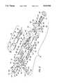
- FIG. 2is an exploded perspective view of an arterial line clamp in accordance with the present invention.
- FIG. 3is an enlarged, somewhat schematic side view of the arterial line clamp of FIG. 2 in an assembled condition.
- FIG. 4is a vertical sectional view of the arterial line clamp of the present invention.
- FIG. 5is a horizontal sectional view taken along line 5--5 of FIG. 3, showing a permanent magnet rotary actuator of the present invention.
- FIG. 5Ais a view similar to FIG. 5 showing the rotary actuator in a displaced rotary position.
- FIG. 5Bis an end view taken along line 5B--5B of FIG. 3.
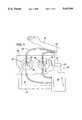
- FIG. 6is an end view taken generally along line 6--6 of FIG. 3, with a top cam cover pivoted open to more clearly show structural details.
- FIG. 8is a horizontal sectional view taken along line 8--8 of FIG. 7, looking towards the tube receiving member and showing manual cam release and stop mechanisms of the present invention in a first position.
- FIG. 9is an identical view to FIG. 8, but showing the cam release and stop mechanisms in a second position.
- FIG. 1illustrates the use of the line clamps of the present invention in the context of single needle hemodialysis. This use is provided by way of illustration only, and is not intended to designate a limitation on the use of the present invention.
- the line clamps of the present inventionmay be used in many contexts in which the control of fluid flow through a flexible tube is required, and is particularly well suited for medical and biotechnological applications.
- FIG. 1there is shown a schematic illustration of a single needle hemodialysis apparatus 20 for removing untreated blood from a patient through a single needle 22 inserted into a vein (not shown) in a patient's arm 24.
- An arterial line 26is connected to the needle 22 for removal of blood from the patient.
- a venous line 28also is connected to the needle 22 for returning treated blood to the patient.
- An arterial line clamp 30 and venous line clamp 32are located on the arterial and venous lines, 26 and 28, respectively, for alternately blocking flow through these lines.
- Blood removed from the patientis pumped through arterial line 26 to the hemodialysis machine 34 where it is treated (not shown) and returned to the patient through venous line 28.
- Pumpingis achieved by a pumping means, such as a peristaltic pump (not shown), located within the hemodialysis machine 34.
- the hemodialysis machinetypically is contained within a frame or housing 36.
- the arterial and venous line clamps, 30 and 32are mounted onto an outer surface of frame 36 in a conventional manner.
- Each of the line clampshas a tube receiving member 38 which provides a channel or seat to retain a portion of the line clamp, again in a conventional manner.
- Tube receiving member 38serves to hold the flexible tube in place next to a rotatable cam (or "tube-occluding cam") 40 which, when rotated in one direction, occludes the flexible tube by pinching it against a side wall of the channel.
- a rotatable cam 40 of arterial line clamp 30is shown in the open position such that blood may flow through arterial line 26 to the hemodialysis machine.
- the rotatable cam 40 of venous line clamp 32is shown in the closed position, thereby occluding venous line 28 and preventing the flow of processed blood to the patient.
- Arterial line clamp 30, venous line clamp 32 and the peristaltic pumpare electrically connected to receive signals from a microprocessor based electronic controller (not shown) within the hemodialysis machine 34 in a manner known in the hemodialysis art.
- Arterial line clamp 30receives control signals from the controller through an electrical line 42
- venous line clamp 32receives control signals from the controller through electrical line 44.
- the controllerreceives feedback electrical signals from Hall sensors (not shown) in arterial line clamp 30 and venous line clamp 32 through electrical lines 46 and 48 respectively. Signals received by the controller through lines 46 and 48 provide information on the respective positions of both rotatable cams 40.
- electrical line 46provides a signal to the controller indicating that arterial line clamp 30 is in the "open” or non-occluded position
- electrical line 48provides a signal to the controller indicating that venous clamp 32 is in the "closed” or occluded position.
- FIG. 2shows an exploded view of arterial line clamp 30 according to one embodiment of the present invention.
- Clamp 30includes a rotary actuator for automatically generating a clamping torque in response to signals from a microprocessor or other control means.
- the rotary actuatorincludes a stator 52 that defines a hollow cylindrical bore 54 into which a permanent magnet-drive shaft assembly 56 is located.
- stator 52is provided with six inwardly protruding projections 58a-58f, circumferentially spaced from one another around bore 54.
- projections 58a-58fare each wrapped with respective coils 60a-60f in a conventional manner to form six electromagnets.
- coils 60a-60fare formed by winding a single length of wire around each projection. The winding direction alternates around successive projections such that coils 60a, 60c and 60e are (for example) wound clockwise and coils 60b, 60d and 60f are wound counterclockwise.
- each coilwill comprise approximately 350 windings of the wire.
- a suitable wirewould be 28 gauge single build insulated thermal class 155 (with a maximum diameter of 0.38 mm, 58.6 ohm resistance per 1000 feet at 20° C).
- the coils 60a-60fform a coil means in which diametrically opposed coils, when energized, have opposite polarities and adjacent coils have opposite polarities, such that the projections produce circumferentially alternating north, south magnetic poles.
- the stator 52 and its component projections 58a-fare formed of non-permanent, but magnetizable material such as soft iron.
- the permanent magnet-drive shaft assembly 56comprises a cylindrical permanent magnet rotor 62, cylindrical backing sleeve 64 and drive shaft insert 66.
- the permanent magnet rotordefines a cylindrical bore into which the cylindrical backing sleeve 64 is snugly press fit or otherwise secured, the outer diameter of the backing sleeve being slightly less than the inner diameter of the magnet rotor.
- the cylindrical backing sleeve 64also defines an internal cylindrical bore into which the drive shaft insert 66 is inserted, again with the outer diameter of the shaft insert being slightly less than the inner diameter of the backing sleeve.
- the drive shaft inserthas a radially expanded collar which rests against an end wall of the backing sleeve when the drive shaft insert is inserted therein.
- the drive shaft insertis fixedly fastened to the backing sleeve by a pair of screws passing through openings 68 in the collar of the drive shaft insert and then threading into corresponding aligned threaded openings 69 in the backing sleeve.
- the backing sleeve and drive shaft insert assemblyis then inserted inside rotor 62 to form part of assembly 56.
- This drive shaft assemblyis rotatably supported by a bearing 72 seated within a bearing sleeve 74.
- Sleeve 74in turn is secured to central portion of a bearing plate 76.
- the foregoing drive shaft assemblyis rotatably supported at a protruding end portion of drive shaft 138 which is journalled in bearing 72, as FIG. 4 illustrates.
- the drive shaft and other components coupled theretoare retained axially in place by a retainer clip 70 (FIG. 2) fastened on the protruding end portion of the drive shaft just outboard of shaft insert 66.
- Bearing plate 76is attached to stator 52 by standoff rivets 78, 80 and 82 and bearing plate-stator screws 84, 86 and 88 which thread into threaded openings in the heads of the standoff rivets.
- the rivetsare fastened to the stator within appropriately positioned openings (not shown) in a peripheral end wall portion of the stator.
- Stop pins 90 and 92are threadedly fastened into an end wall portion of backing sleeve 64 for rotation therewith. Stop pins 90 and 92 project from the backing sleeve through respective raceways 94 and 96 cut in bearing plate 76.
- the stop pinsare each provided with cushioning means which, in this preferred embodiment, includes respective plastic sleeves 98 and 100.
- raceways 94, 96define stop limits for the movement of the stop pins.
- the racewayswhich have an arcuate configuration due to the rotational movement of the rotary actuator, preferably permit the stop pins to travel along a circular path of about 45°.
- Sleeves 100muffle the noise created as the stop pins periodically contact the stop limits by preventing the metal to metal contact which would otherwise occur.
- a cylindrical spring 101is attached at one end to each stop pin 90, 92 and at its other end to a respective anchor pin 102, 104.
- the springsact as a counterbalanced biasing means urging the stop pins to move to the end of their respective raceways closest to the anchor, thereby forcing the rotary actuator coupled thereto to its "open" non-occluded position unless counteracted by a greater rotational force.
- base plate 120is mounted proximate to one side of stator 52 by means of standoff rivets 132, 134 and 136, and base plate stator screws 122, 124 and 126 which thread into respective heads of rivets 132, 134, 136.
- Mounting plate 130in turn is attached to the base plate 120 by means of screws (not shown) passing through the mounting tubes 156 and threading into the inboard side of the mounting plate. Tubes 156 provide access openings for a screwdriver to engage the screws without contacting and possibly damaging coils 60.
- cover 148is pivoted on its supporting cover shaft to a closed position in which the cover overlies the flexible tube to prevent same from being displaced out of the channel.
- a cover shaft retainer clip 150(FIG. 2)
- cover shaft retainer washer 152(FIG. 2)
- cover torsion spring 154(FIG. 2) are seated on one end of the cover shaft between base plate 120 and stator 52 so as to axially retain the cover shaft in place and provide a biasing torque urging the cover to its closed "tube retained" position.
- a semicircular printed circuit board 158is mounted in a conventional manner to bearing plate 76 on its outboard side.
- Circuit board 158has a semicircular notch 160 to provide clearance for some of the components on the outboard side of bearing plate 76.
- the circuit boardcarries conventional electronic circuitry known in the art for directing and controlling current flow to stator coils 58a-f of stator 52. Electrical wires 164 joined to the control circuitry on the circuit board 158 pass through appropriate openings in the bearing plate to operably connect to coils 58a-f.
- the control circuitry on circuit board 158also receives control signals from the microprocessor (not shown) or other suitable controller through electrical lines such as line 42 (FIG. 1).
- FIGS. 3 and 4schematically show the Hall sensor positioned generally between one of the stator coils and an adjacent pole portion of magnet 62. It will be appreciated that the Hall sensor is located in the magnetic field of the pole portion so as to detect rotation of the magnet when the adjacent pole orientation changes from north to south (or vice versa). This change in orientation is signalled electrically to the microprocessor which is programmed to associate the particular pole orientation of the magnet with either an "open” or "occluded” status of the clamping cam.
- stator coils 58a-58fWhen power is supplied to stator coils 58a-58f, in response to signals received from the hemodialysis machine microprocessor through the circuit board 158 and suitable electrical wiring, the electromagnetic fields are activated.
- the coilsare wound so that, when energized, each coil creates an electromagnetic field of the same polarity as the permanent magnet pole portion directly across from the coil thereby applying a repelling magnet force to the permanent magnet.
- These electromagnetic fieldscause the permanent magnet to rotate in a counterclockwise direction, as shown by the arrow in FIG. 5A, to a more dynamically stable position in which the permanent magnet pole portions have aligned themselves with a coil of opposite polarity.
- This rotational movementproduces rotation of the drive shaft 138 and thereby, rotation of the rotatable cam 40 to its occluded position.
- the torque generated by rotation of the permanent magnetis sufficient to overcome the biasing action of the springs 101 and cause the pins 90 and 92 to move to the limits of the raceways 94 and 96, respectively, such that springs 101 are maximally extended (shown in FIG. 5B).
- the rotatable cam 40will turn through a maximum angle of 45 degrees, as illustrated in FIG. 6, and will thereby occlude the flexible tube mounted in the tube retaining member 38.
- the maximum rotation angle of 45°is defined by the travel of pins 90 and 92 in raceways 94 and 96, respectively (FIG. 5B).
- the permanent magnetcomprises a ferrite magnet, although other types of magnets may also be used.
- the arterial line clampproduces at least 8 inch pounds of torque, and preferably more than 10 inch pounds of torque.
- the rotary actuator of the present inventionpreferably is supplied with a 24 volt direct current power supply and draws 0.5 amps of current, therefore consuming 12 watts of power.
- the above descriptionsets forth a preferred embodiment as an arterial line clamp in which the spring biasing mechanism causes the clamp to be in the "open” or non-occluded position when power is withheld from the electromagnet coils. It will be appreciated that essentially the same design can be utilized to produce a venous or "safety” clamp simply by arranging the drive shaft-spring biasing mechanism such that the spring biasing mechanism causes the clamp to be in a "closed” position when power is withheld from the electromagnet coils. Because of safety considerations in the single needle hemodialysis context, the biasing spring mechanism in a venous clamp context preferably is designed to supply a greater biasing force to the drive shaft assembly than springs used in an arterial clamp design.
- parameterssuch as type and strength of magnet, amount of power supplied to the stator coils and cam length relative to its axis of rotation, will be selected in a known manner to produce at least 10 inch pounds of torque on the cam and, preferably at least 14 inch pounds of torque.
- increased torquemay be produced by using a thicker gauge of windings on the stator coils which thereby draw a greater current and produce a correspondingly stronger electromagnetic field.
- a safety clamp according to this embodimentmay be supplied with a 24 volt direct current power supply and draw 1.0 amp of current, therefore consuming 24 watts of power.
- the increased torquemay be obtained by utilizing a rare earth permanent magnet in place of the ferrite permanent magnet.
- Suitable rare earth permanent magnetsinclude samarium cobalt and iron neodymium magnets.
- the clamps of the present inventionoperate on relatively low voltage direct current, heat generation problems associated with conventional clamps are avoided. Furthermore, the location and design of the stop mechanism (the steel stop pins mounted with noise-reducing sleeves) produce significantly less noise than conventional clamps. Finally, the clamps of the present invention are more compact, reliable and operate more efficiently than conventional solenoid design clamps.
- the preferred embodiment described aboveis illustrative only of the principle of the rotary actuator clamp design, and that variations in this design which rely on the underlying concept set forth herein are possible.
- the number of electromagnets in the stator and the corresponding number of pole-pairs of the permanent magnetmay be increased or reduced.
- the rotation of the drive shaftis correspondingly reduced.
- FIG. 7shows a vertical sectional view of a venous line clamp in accordance with one particular alternate embodiment of the present invention.
- the construction of this embodimentis the same as the embodiments illustrated in FIGS. 2-6, except as otherwise shown in FIGS. 7-10 and discussed below.
- FIG. 7shows an alternative mechanism for mounting drive shaft 138 onto the drive shaft insert 66.
- a nut 180is threaded onto externally threaded section 182 of drive shaft 138. The nut 180 thereby retains the drive shaft 138, and other components coupled thereto, axially in place in the drive shaft insert 66.
- the pin and raceway stop mechanism used to limit the maximum rotation of the drive shaft 138is replaced by a fixed stop 168 mounted to or integrally formed on the in-board side of fixed base plate 120.
- Stop 168carries a single tooth projection which cooperates with a cam collar (or “rotation-limiting cam") 170 mounted on drive shaft 138.
- Collar 170has a complementary shaped square opening to receive a square portion of shaft 138 so that the collar and shaft rotate together.
- Cam collar 170is generally circular in section, except for two arcuate notches, a first notch 169 and second notch 171, formed in the periphery of the cam collar (see FIGS. 8 and 9).
- notch 169 and the tooth of stop 168are sized, configured and arranged to permit shaft 138 and the occluding cam 40 coupled thereto to rotate about 45° between the open and occluded positions.
- An angular rotation of the cam shaft of about 45°is selected as a preferred embodiment of the present invention, both for the cam collar herein described and the pins and raceways design described above as the preferred embodiment.
- This parameteris a function of several obvious variables, including the effective "lever" length of cam 40, configuration of cam 40 and its relative position to the flexible tube, and hence can vary depending upon the design of the line clamp. These parameters are selected such that cam 40 does not pinch or crimp the flexible tube when disposed in the open position, but does effectively and consistently occlude the flexible tube to stop all flow therethrough when disposed in the occluded position without permanently crimping or otherwise damaging the flexible tube.
- FIG. 7also shows an alternative biasing means or spring tension mechanism 172 in place of the dual spring mechanism shown in FIGS. 2 and 5B.
- Spring tension mechanism 172includes a helical tension spring 173 which is mounted outboard of bearing plate 76. One end of the helical tension spring is fixedly attached to a shaft extension 175 fastened to drive shaft 138 by means of a screw 174. The other end of the helical spring is fixedly fastened to bearing plate 76.
- the spring tension mechanism 172is coupled to drive shaft 138 in a manner such that the drive shaft and its rotatable cam 40 is biased to the tube occluding position.
- FIGS. 7-10show a manual cam release means by which cam 40 can be manually rotated into the "open" position to release the flexible tube.
- pivotable cover 148has an integrally connected cover shaft 140 from which protrudes, at a distal end thereof, an integrally formed cam tooth 176. It will be appreciated that cover 148, shaft 140 and tooth 176 all rotate as a unit. The cam tooth projects into and cooperates with the second notch 171 of cam collar 170.
- cover 148is closed to retain the flexible tube in its occluded position (with power off) in the channel and, therefore, is rotated, causing cam tooth 176 is inoperative.
- cover 148is rotated, causing cam tooth 176 to rotate clockwise to the position shown in FIG. 9.
- the cam toothengages cam collar 170, causing drive shaft 138 and occlusion cam 40 coupled thereto to rotate against the bias of the helical spring 173.
- Cam 40is thus manually rotated to the "open" position to permit the flexible tube to be removed.
Landscapes
- Engineering & Computer Science (AREA)
- General Engineering & Computer Science (AREA)
- Mechanical Engineering (AREA)
- External Artificial Organs (AREA)
- Valve-Gear Or Valve Arrangements (AREA)
- Fluid-Driven Valves (AREA)
- Details Of Reciprocating Pumps (AREA)
- Mechanically-Actuated Valves (AREA)
- Reciprocating Pumps (AREA)
- Infusion, Injection, And Reservoir Apparatuses (AREA)
Abstract
Description
Claims (2)
Priority Applications (5)
| Application Number | Priority Date | Filing Date | Title |
|---|---|---|---|
| US08/033,621US5413566A (en) | 1993-03-16 | 1993-03-16 | Line clamp |
| AT94850035TATE162880T1 (en) | 1993-03-16 | 1994-03-10 | PINCH VALVE |
| DE69408182TDE69408182T2 (en) | 1993-03-16 | 1994-03-10 | Pinch valve |
| EP94850035AEP0616155B1 (en) | 1993-03-16 | 1994-03-10 | Pinch valve |
| JP6045851AJPH06341374A (en) | 1993-03-16 | 1994-03-16 | Fluid controller in flexible pipe |
Applications Claiming Priority (1)
| Application Number | Priority Date | Filing Date | Title |
|---|---|---|---|
| US08/033,621US5413566A (en) | 1993-03-16 | 1993-03-16 | Line clamp |
Publications (1)
| Publication Number | Publication Date |
|---|---|
| US5413566Atrue US5413566A (en) | 1995-05-09 |
Family
ID=21871457
Family Applications (1)
| Application Number | Title | Priority Date | Filing Date |
|---|---|---|---|
| US08/033,621Expired - Fee RelatedUS5413566A (en) | 1993-03-16 | 1993-03-16 | Line clamp |
Country Status (5)
| Country | Link |
|---|---|
| US (1) | US5413566A (en) |
| EP (1) | EP0616155B1 (en) |
| JP (1) | JPH06341374A (en) |
| AT (1) | ATE162880T1 (en) |
| DE (1) | DE69408182T2 (en) |
Cited By (39)
| Publication number | Priority date | Publication date | Assignee | Title |
|---|---|---|---|---|
| US5684349A (en)* | 1994-07-08 | 1997-11-04 | Kayaba Kogyo Kabushiki Kaisha | Electromagnetic rotary actuator |
| US5684350A (en)* | 1994-09-08 | 1997-11-04 | Kayaba Kogyo Kabushiki Kaisha | Electromagnetic rotary actuator and housing for electronic devices |
| EP0831259A3 (en)* | 1996-09-12 | 1998-05-13 | Siemens-Elema AB | Flow regulator |
| US6722865B2 (en) | 2001-09-07 | 2004-04-20 | Terumorcardiovascular Systems Corporation | Universal tube clamp assembly |
| US20040102716A1 (en)* | 2000-11-02 | 2004-05-27 | Mobbs William Leonard | Means for stripping blood-lines |
| US20060173419A1 (en)* | 2005-02-02 | 2006-08-03 | Malcolm David R | Medical fluid delivery system and method relating to the same |
| US20070171319A1 (en)* | 2006-01-26 | 2007-07-26 | Sanyo Epson Imaging Devices Corporation | Liquid crystal apparatus and electronic device |
| US20080253912A1 (en)* | 2007-02-27 | 2008-10-16 | Deka Products Limited Partnership | Pumping Cassette |
| US20090099498A1 (en)* | 2007-10-12 | 2009-04-16 | Deka Products Limited Partnership | Systems, Devices and Methods for Cardiopulmonary Treatment and Procedures |
| US20100057016A1 (en)* | 2008-08-27 | 2010-03-04 | Deka Products Limited Partnership | Occluder for a medical infusion system |
| US20110098635A1 (en)* | 2008-01-23 | 2011-04-28 | Deka Research & Development | Fluid flow occluder and methods of use for medical treatment systems |
| US8042563B2 (en) | 2007-02-27 | 2011-10-25 | Deka Products Limited Partnership | Cassette system integrated apparatus |
| US20110308629A1 (en)* | 2010-02-12 | 2011-12-22 | Griffith William W | Vacuum Valve Apparatus and Method |
| US8246826B2 (en) | 2007-02-27 | 2012-08-21 | Deka Products Limited Partnership | Hemodialysis systems and methods |
| US8292594B2 (en) | 2006-04-14 | 2012-10-23 | Deka Products Limited Partnership | Fluid pumping systems, devices and methods |
| US8357298B2 (en) | 2007-02-27 | 2013-01-22 | Deka Products Limited Partnership | Hemodialysis systems and methods |
| US8393690B2 (en) | 2007-02-27 | 2013-03-12 | Deka Products Limited Partnership | Enclosure for a portable hemodialysis system |
| US8409441B2 (en) | 2007-02-27 | 2013-04-02 | Deka Products Limited Partnership | Blood treatment systems and methods |
| US8425471B2 (en) | 2007-02-27 | 2013-04-23 | Deka Products Limited Partnership | Reagent supply for a hemodialysis system |
| US8491184B2 (en) | 2007-02-27 | 2013-07-23 | Deka Products Limited Partnership | Sensor apparatus systems, devices and methods |
| US8562834B2 (en) | 2007-02-27 | 2013-10-22 | Deka Products Limited Partnership | Modular assembly for a portable hemodialysis system |
| US8771508B2 (en) | 2008-08-27 | 2014-07-08 | Deka Products Limited Partnership | Dialyzer cartridge mounting arrangement for a hemodialysis system |
| US9028691B2 (en) | 2007-02-27 | 2015-05-12 | Deka Products Limited Partnership | Blood circuit assembly for a hemodialysis system |
| US9057363B2 (en) | 2007-12-10 | 2015-06-16 | Bayer Medical Care, Inc. | Continuous fluid delivery system |
| US9364655B2 (en) | 2012-05-24 | 2016-06-14 | Deka Products Limited Partnership | Flexible tubing occlusion assembly |
| US9517295B2 (en) | 2007-02-27 | 2016-12-13 | Deka Products Limited Partnership | Blood treatment systems and methods |
| US9597442B2 (en) | 2007-02-27 | 2017-03-21 | Deka Products Limited Partnership | Air trap for a medical infusion device |
| US9724458B2 (en) | 2011-05-24 | 2017-08-08 | Deka Products Limited Partnership | Hemodialysis system |
| WO2017195097A1 (en)* | 2016-05-09 | 2017-11-16 | Picobrew, Inc. | Bi-stable electrically actuated valve |
| US10201650B2 (en) | 2009-10-30 | 2019-02-12 | Deka Products Limited Partnership | Apparatus and method for detecting disconnection of an intravascular access device |
| US10308903B2 (en) | 2014-09-17 | 2019-06-04 | Picobrew, Inc. | Foam reducing device |
| US10377981B2 (en) | 2015-03-17 | 2019-08-13 | Picobrew, Inc. | Software tuning of recipes for beer brewing system |
| US10463983B2 (en) | 2017-03-31 | 2019-11-05 | Picobrew, Inc. | Distillation and essence extractor insert for beer brewing machine |
| US10479966B2 (en) | 2015-07-31 | 2019-11-19 | Picobrew, Inc. | Fermentation monitoring and management |
| US10507319B2 (en) | 2015-01-09 | 2019-12-17 | Bayer Healthcare Llc | Multiple fluid delivery system with multi-use disposable set and features thereof |
| US10537671B2 (en) | 2006-04-14 | 2020-01-21 | Deka Products Limited Partnership | Automated control mechanisms in a hemodialysis apparatus |
| US11299695B2 (en) | 2015-07-23 | 2022-04-12 | PB Funding Group, LLC | Beer making machine with direct steam injection |
| US11678760B2 (en) | 2011-03-03 | 2023-06-20 | PB Funding Group, LLC | Multifunctional brewing system for coffee, beer, and other beverages |
| US11753610B2 (en) | 2011-03-03 | 2023-09-12 | PB Funding Group, LLC | Self healing controller for beer brewing system |
Families Citing this family (2)
| Publication number | Priority date | Publication date | Assignee | Title |
|---|---|---|---|---|
| DE102015014741A1 (en)* | 2015-11-13 | 2017-05-18 | Fresenius Medical Care Deutschland Gmbh | Hose clamp for a blood treatment device |
| DE102018214989A1 (en)* | 2017-10-12 | 2019-04-18 | Fresenius Medical Care Deutschland Gmbh | jam |
Citations (23)
| Publication number | Priority date | Publication date | Assignee | Title |
|---|---|---|---|---|
| FR452234A (en)* | 1911-12-20 | 1913-05-10 | James Dennis Roots | Advanced carburettor |
| US3248499A (en)* | 1962-09-13 | 1966-04-26 | Digital Analog Technical Assoc | Electro-mechanical actuator with permanent magnet |
| US3523523A (en)* | 1966-06-30 | 1970-08-11 | Contraves Ag | Power driven medical injector syringe with electromagnetic coupling means |
| US3694782A (en)* | 1970-11-20 | 1972-09-26 | Ralph D Ray | Rotary actuator |
| US3817237A (en)* | 1972-08-24 | 1974-06-18 | Medtronic Inc | Regulatory apparatus |
| US3985134A (en)* | 1973-11-26 | 1976-10-12 | Rhone-Poulenc S.A. | Extracorporeal blood circuit |
| US4061142A (en)* | 1976-06-16 | 1977-12-06 | Sandoz, Inc. | Apparatus for controlling blood flow |
| US4190536A (en)* | 1977-02-23 | 1980-02-26 | A/S Nycotron | Peristaltic pumping means for blood dialysis |
| US4227164A (en)* | 1977-08-20 | 1980-10-07 | Shinano Tokki Corporation | Electromagnetic rotating apparatus |
| US4397642A (en)* | 1981-12-31 | 1983-08-09 | Baxter Travenol Laboratories, Inc. | Motor driven occlusion controller for liquid infusion and the like |
| US4601702A (en)* | 1984-05-21 | 1986-07-22 | Quest Medical, Inc. | Volumetric infusion actuator |
| US4616801A (en)* | 1983-01-24 | 1986-10-14 | Siemens Elema Ab | Apparatus to regulate the flow of liquids |
| US4643714A (en)* | 1985-08-05 | 1987-02-17 | Cobe Laboratories, Inc. | Single needle apparatus |
| US4696669A (en)* | 1986-03-24 | 1987-09-29 | Menhusen Monty J | Hand held combination flush with adjustable nozzle and/or suction apparatus |
| US4795929A (en)* | 1986-08-01 | 1989-01-03 | Logus Manufacturing Corp. | Rotary actuator |
| US4878646A (en)* | 1988-08-15 | 1989-11-07 | Critkon, Inc. | Pinch valve mechanism for a parenteral infusion system |
| US4928028A (en)* | 1989-02-23 | 1990-05-22 | Hydraulic Units, Inc. | Proportional permanent magnet force actuator |
| US5034670A (en)* | 1989-04-21 | 1991-07-23 | Mitsubishi Denki K.K. | Control circuit for electromagnetic actuator |
| US5067359A (en)* | 1989-07-19 | 1991-11-26 | Fresenius Ag | Apparatus for clamping flexible tubes |
| US5082025A (en)* | 1990-11-23 | 1992-01-21 | Dlp, Inc. | Antegrade-retrograde switch and occluder and system for using the same |
| US5146126A (en)* | 1991-09-05 | 1992-09-08 | Hr Textron Inc. | Adjustable rotor assembly |
| US5221268A (en)* | 1991-12-06 | 1993-06-22 | Block Medical, Inc. | Multiple dose control apparatus |
| US5254083A (en)* | 1992-02-10 | 1993-10-19 | Conmed Corporation | Suction and irrigation apparatus |
Family Cites Families (1)
| Publication number | Priority date | Publication date | Assignee | Title |
|---|---|---|---|---|
| FR2660981B1 (en)* | 1990-04-12 | 1992-08-14 | Sextant Avionique | ELECTRICALLY CONTROLLED VARIABLE FLOW VALVE. |
- 1993
- 1993-03-16USUS08/033,621patent/US5413566A/ennot_activeExpired - Fee Related
- 1994
- 1994-03-10EPEP94850035Apatent/EP0616155B1/ennot_activeExpired - Lifetime
- 1994-03-10ATAT94850035Tpatent/ATE162880T1/enactive
- 1994-03-10DEDE69408182Tpatent/DE69408182T2/ennot_activeExpired - Fee Related
- 1994-03-16JPJP6045851Apatent/JPH06341374A/enactivePending
Patent Citations (23)
| Publication number | Priority date | Publication date | Assignee | Title |
|---|---|---|---|---|
| FR452234A (en)* | 1911-12-20 | 1913-05-10 | James Dennis Roots | Advanced carburettor |
| US3248499A (en)* | 1962-09-13 | 1966-04-26 | Digital Analog Technical Assoc | Electro-mechanical actuator with permanent magnet |
| US3523523A (en)* | 1966-06-30 | 1970-08-11 | Contraves Ag | Power driven medical injector syringe with electromagnetic coupling means |
| US3694782A (en)* | 1970-11-20 | 1972-09-26 | Ralph D Ray | Rotary actuator |
| US3817237A (en)* | 1972-08-24 | 1974-06-18 | Medtronic Inc | Regulatory apparatus |
| US3985134A (en)* | 1973-11-26 | 1976-10-12 | Rhone-Poulenc S.A. | Extracorporeal blood circuit |
| US4061142A (en)* | 1976-06-16 | 1977-12-06 | Sandoz, Inc. | Apparatus for controlling blood flow |
| US4190536A (en)* | 1977-02-23 | 1980-02-26 | A/S Nycotron | Peristaltic pumping means for blood dialysis |
| US4227164A (en)* | 1977-08-20 | 1980-10-07 | Shinano Tokki Corporation | Electromagnetic rotating apparatus |
| US4397642A (en)* | 1981-12-31 | 1983-08-09 | Baxter Travenol Laboratories, Inc. | Motor driven occlusion controller for liquid infusion and the like |
| US4616801A (en)* | 1983-01-24 | 1986-10-14 | Siemens Elema Ab | Apparatus to regulate the flow of liquids |
| US4601702A (en)* | 1984-05-21 | 1986-07-22 | Quest Medical, Inc. | Volumetric infusion actuator |
| US4643714A (en)* | 1985-08-05 | 1987-02-17 | Cobe Laboratories, Inc. | Single needle apparatus |
| US4696669A (en)* | 1986-03-24 | 1987-09-29 | Menhusen Monty J | Hand held combination flush with adjustable nozzle and/or suction apparatus |
| US4795929A (en)* | 1986-08-01 | 1989-01-03 | Logus Manufacturing Corp. | Rotary actuator |
| US4878646A (en)* | 1988-08-15 | 1989-11-07 | Critkon, Inc. | Pinch valve mechanism for a parenteral infusion system |
| US4928028A (en)* | 1989-02-23 | 1990-05-22 | Hydraulic Units, Inc. | Proportional permanent magnet force actuator |
| US5034670A (en)* | 1989-04-21 | 1991-07-23 | Mitsubishi Denki K.K. | Control circuit for electromagnetic actuator |
| US5067359A (en)* | 1989-07-19 | 1991-11-26 | Fresenius Ag | Apparatus for clamping flexible tubes |
| US5082025A (en)* | 1990-11-23 | 1992-01-21 | Dlp, Inc. | Antegrade-retrograde switch and occluder and system for using the same |
| US5146126A (en)* | 1991-09-05 | 1992-09-08 | Hr Textron Inc. | Adjustable rotor assembly |
| US5221268A (en)* | 1991-12-06 | 1993-06-22 | Block Medical, Inc. | Multiple dose control apparatus |
| US5254083A (en)* | 1992-02-10 | 1993-10-19 | Conmed Corporation | Suction and irrigation apparatus |
Non-Patent Citations (1)
| Title |
|---|
| Communication, European Search Report and Annex to European Search Report dated Jul. 21, 1994 (3 pp.).* |
Cited By (86)
| Publication number | Priority date | Publication date | Assignee | Title |
|---|---|---|---|---|
| US5684349A (en)* | 1994-07-08 | 1997-11-04 | Kayaba Kogyo Kabushiki Kaisha | Electromagnetic rotary actuator |
| US5684350A (en)* | 1994-09-08 | 1997-11-04 | Kayaba Kogyo Kabushiki Kaisha | Electromagnetic rotary actuator and housing for electronic devices |
| EP0831259A3 (en)* | 1996-09-12 | 1998-05-13 | Siemens-Elema AB | Flow regulator |
| US6062218A (en)* | 1996-09-12 | 2000-05-16 | Siemens-Elema Ab | Flow regulator |
| US20040102716A1 (en)* | 2000-11-02 | 2004-05-27 | Mobbs William Leonard | Means for stripping blood-lines |
| US6722865B2 (en) | 2001-09-07 | 2004-04-20 | Terumorcardiovascular Systems Corporation | Universal tube clamp assembly |
| US20080086088A1 (en)* | 2003-07-23 | 2008-04-10 | Universal Infusion Technology, Llc | Medical fluid delivery system and method relating to the same |
| US7896017B2 (en) | 2003-07-23 | 2011-03-01 | StnDrd Infusion Corp. | Medical fluid delivery system and method relating to the same |
| US20060173419A1 (en)* | 2005-02-02 | 2006-08-03 | Malcolm David R | Medical fluid delivery system and method relating to the same |
| US7367358B2 (en) | 2005-02-02 | 2008-05-06 | Universal Infusion Technology, Llc | Medical fluid delivery system and method relating to the same |
| US20070171319A1 (en)* | 2006-01-26 | 2007-07-26 | Sanyo Epson Imaging Devices Corporation | Liquid crystal apparatus and electronic device |
| US10537671B2 (en) | 2006-04-14 | 2020-01-21 | Deka Products Limited Partnership | Automated control mechanisms in a hemodialysis apparatus |
| US8870549B2 (en) | 2006-04-14 | 2014-10-28 | Deka Products Limited Partnership | Fluid pumping systems, devices and methods |
| US8292594B2 (en) | 2006-04-14 | 2012-10-23 | Deka Products Limited Partnership | Fluid pumping systems, devices and methods |
| US8992075B2 (en) | 2007-02-27 | 2015-03-31 | Deka Products Limited Partnership | Sensor apparatus systems, devices and methods |
| US9517295B2 (en) | 2007-02-27 | 2016-12-13 | Deka Products Limited Partnership | Blood treatment systems and methods |
| US8042563B2 (en) | 2007-02-27 | 2011-10-25 | Deka Products Limited Partnership | Cassette system integrated apparatus |
| US12059516B2 (en) | 2007-02-27 | 2024-08-13 | Deka Products Limited Partnership | Blood circuit assembly for a hemodialysis system |
| US10851769B2 (en) | 2007-02-27 | 2020-12-01 | Deka Products Limited Partnership | Pumping cassette |
| US8246826B2 (en) | 2007-02-27 | 2012-08-21 | Deka Products Limited Partnership | Hemodialysis systems and methods |
| US8273049B2 (en) | 2007-02-27 | 2012-09-25 | Deka Products Limited Partnership | Pumping cassette |
| US20080253912A1 (en)* | 2007-02-27 | 2008-10-16 | Deka Products Limited Partnership | Pumping Cassette |
| US8317492B2 (en) | 2007-02-27 | 2012-11-27 | Deka Products Limited Partnership | Pumping cassette |
| US8357298B2 (en) | 2007-02-27 | 2013-01-22 | Deka Products Limited Partnership | Hemodialysis systems and methods |
| US8393690B2 (en) | 2007-02-27 | 2013-03-12 | Deka Products Limited Partnership | Enclosure for a portable hemodialysis system |
| US8409441B2 (en) | 2007-02-27 | 2013-04-02 | Deka Products Limited Partnership | Blood treatment systems and methods |
| US8425471B2 (en) | 2007-02-27 | 2013-04-23 | Deka Products Limited Partnership | Reagent supply for a hemodialysis system |
| US8459292B2 (en) | 2007-02-27 | 2013-06-11 | Deka Products Limited Partnership | Cassette system integrated apparatus |
| US8491184B2 (en) | 2007-02-27 | 2013-07-23 | Deka Products Limited Partnership | Sensor apparatus systems, devices and methods |
| US8499780B2 (en) | 2007-02-27 | 2013-08-06 | Deka Products Limited Partnership | Cassette system integrated apparatus |
| US8545698B2 (en) | 2007-02-27 | 2013-10-01 | Deka Products Limited Partnership | Hemodialysis systems and methods |
| US8562834B2 (en) | 2007-02-27 | 2013-10-22 | Deka Products Limited Partnership | Modular assembly for a portable hemodialysis system |
| US10500327B2 (en) | 2007-02-27 | 2019-12-10 | Deka Products Limited Partnership | Blood circuit assembly for a hemodialysis system |
| US8721884B2 (en) | 2007-02-27 | 2014-05-13 | Deka Products Limited Partnership | Hemodialysis systems and methods |
| US8721879B2 (en) | 2007-02-27 | 2014-05-13 | Deka Products Limited Partnership | Hemodialysis systems and methods |
| US10441697B2 (en) | 2007-02-27 | 2019-10-15 | Deka Products Limited Partnership | Modular assembly for a portable hemodialysis system |
| US10077766B2 (en) | 2007-02-27 | 2018-09-18 | Deka Products Limited Partnership | Pumping cassette |
| US9987407B2 (en) | 2007-02-27 | 2018-06-05 | Deka Products Limited Partnership | Blood circuit assembly for a hemodialysis system |
| US8888470B2 (en) | 2007-02-27 | 2014-11-18 | Deka Products Limited Partnership | Pumping cassette |
| US8926294B2 (en) | 2007-02-27 | 2015-01-06 | Deka Products Limited Partnership | Pumping cassette |
| US8985133B2 (en) | 2007-02-27 | 2015-03-24 | Deka Products Limited Partnership | Cassette system integrated apparatus |
| US8992189B2 (en) | 2007-02-27 | 2015-03-31 | Deka Products Limited Partnership | Cassette system integrated apparatus |
| US9951768B2 (en) | 2007-02-27 | 2018-04-24 | Deka Products Limited Partnership | Cassette system integrated apparatus |
| US9700660B2 (en) | 2007-02-27 | 2017-07-11 | Deka Products Limited Partnership | Pumping cassette |
| US9028691B2 (en) | 2007-02-27 | 2015-05-12 | Deka Products Limited Partnership | Blood circuit assembly for a hemodialysis system |
| US9677554B2 (en) | 2007-02-27 | 2017-06-13 | Deka Products Limited Partnership | Cassette system integrated apparatus |
| US9115708B2 (en) | 2007-02-27 | 2015-08-25 | Deka Products Limited Partnership | Fluid balancing systems and methods |
| US9272082B2 (en) | 2007-02-27 | 2016-03-01 | Deka Products Limited Partnership | Pumping cassette |
| US9302037B2 (en) | 2007-02-27 | 2016-04-05 | Deka Products Limited Partnership | Hemodialysis systems and methods |
| US9649418B2 (en) | 2007-02-27 | 2017-05-16 | Deka Products Limited Partnership | Pumping cassette |
| US7967022B2 (en) | 2007-02-27 | 2011-06-28 | Deka Products Limited Partnership | Cassette system integrated apparatus |
| US9535021B2 (en) | 2007-02-27 | 2017-01-03 | Deka Products Limited Partnership | Sensor apparatus systems, devices and methods |
| US9539379B2 (en) | 2007-02-27 | 2017-01-10 | Deka Products Limited Partnership | Enclosure for a portable hemodialysis system |
| US9555179B2 (en) | 2007-02-27 | 2017-01-31 | Deka Products Limited Partnership | Hemodialysis systems and methods |
| US9597442B2 (en) | 2007-02-27 | 2017-03-21 | Deka Products Limited Partnership | Air trap for a medical infusion device |
| US9603985B2 (en) | 2007-02-27 | 2017-03-28 | Deka Products Limited Partnership | Blood treatment systems and methods |
| US8105265B2 (en) | 2007-10-12 | 2012-01-31 | Deka Products Limited Partnership | Systems, devices and methods for cardiopulmonary treatment and procedures |
| US20090099498A1 (en)* | 2007-10-12 | 2009-04-16 | Deka Products Limited Partnership | Systems, Devices and Methods for Cardiopulmonary Treatment and Procedures |
| US9057363B2 (en) | 2007-12-10 | 2015-06-16 | Bayer Medical Care, Inc. | Continuous fluid delivery system |
| US9839776B2 (en) | 2008-01-23 | 2017-12-12 | Deka Products Limited Partnership | Fluid flow occluder and methods of use for medical treatment systems |
| US9028440B2 (en) | 2008-01-23 | 2015-05-12 | Deka Products Limited Partnership | Fluid flow occluder and methods of use for medical treatment systems |
| US20110098635A1 (en)* | 2008-01-23 | 2011-04-28 | Deka Research & Development | Fluid flow occluder and methods of use for medical treatment systems |
| US8771508B2 (en) | 2008-08-27 | 2014-07-08 | Deka Products Limited Partnership | Dialyzer cartridge mounting arrangement for a hemodialysis system |
| US20100057016A1 (en)* | 2008-08-27 | 2010-03-04 | Deka Products Limited Partnership | Occluder for a medical infusion system |
| US8863772B2 (en)* | 2008-08-27 | 2014-10-21 | Deka Products Limited Partnership | Occluder for a medical infusion system |
| US10201650B2 (en) | 2009-10-30 | 2019-02-12 | Deka Products Limited Partnership | Apparatus and method for detecting disconnection of an intravascular access device |
| US8671990B2 (en)* | 2010-02-12 | 2014-03-18 | Moog Inc. | Vacuum valve apparatus and method |
| US20110308629A1 (en)* | 2010-02-12 | 2011-12-22 | Griffith William W | Vacuum Valve Apparatus and Method |
| US11753610B2 (en) | 2011-03-03 | 2023-09-12 | PB Funding Group, LLC | Self healing controller for beer brewing system |
| US11678760B2 (en) | 2011-03-03 | 2023-06-20 | PB Funding Group, LLC | Multifunctional brewing system for coffee, beer, and other beverages |
| US10780213B2 (en) | 2011-05-24 | 2020-09-22 | Deka Products Limited Partnership | Hemodialysis system |
| US9724458B2 (en) | 2011-05-24 | 2017-08-08 | Deka Products Limited Partnership | Hemodialysis system |
| US9700711B2 (en) | 2012-05-24 | 2017-07-11 | Deka Products Limited Partnership | Flexible tubing occlusion assembly |
| US9364655B2 (en) | 2012-05-24 | 2016-06-14 | Deka Products Limited Partnership | Flexible tubing occlusion assembly |
| US11766554B2 (en) | 2012-05-24 | 2023-09-26 | Deka Products Limited Partnership | Flexible tubing occlusion assembly |
| US10850089B2 (en) | 2012-05-24 | 2020-12-01 | Deka Products Limited Partnership | Flexible tubing occlusion assembly |
| US10308903B2 (en) | 2014-09-17 | 2019-06-04 | Picobrew, Inc. | Foam reducing device |
| US11491318B2 (en) | 2015-01-09 | 2022-11-08 | Bayer Healthcare Llc | Multiple fluid delivery system with multi-use disposable set and features thereof |
| US10507319B2 (en) | 2015-01-09 | 2019-12-17 | Bayer Healthcare Llc | Multiple fluid delivery system with multi-use disposable set and features thereof |
| US12201802B2 (en) | 2015-01-09 | 2025-01-21 | Bayer Healthcare Llc | Multiple fluid delivery system with multi-use disposable set and features thereof |
| US10377981B2 (en) | 2015-03-17 | 2019-08-13 | Picobrew, Inc. | Software tuning of recipes for beer brewing system |
| US11299695B2 (en) | 2015-07-23 | 2022-04-12 | PB Funding Group, LLC | Beer making machine with direct steam injection |
| US10479966B2 (en) | 2015-07-31 | 2019-11-19 | Picobrew, Inc. | Fermentation monitoring and management |
| WO2017195097A1 (en)* | 2016-05-09 | 2017-11-16 | Picobrew, Inc. | Bi-stable electrically actuated valve |
| US10161533B2 (en) | 2016-05-09 | 2018-12-25 | Picobrew, Inc. | Bi-stable electrically actuated valve |
| US10463983B2 (en) | 2017-03-31 | 2019-11-05 | Picobrew, Inc. | Distillation and essence extractor insert for beer brewing machine |
Also Published As
| Publication number | Publication date |
|---|---|
| DE69408182D1 (en) | 1998-03-05 |
| ATE162880T1 (en) | 1998-02-15 |
| EP0616155A1 (en) | 1994-09-21 |
| DE69408182T2 (en) | 1998-08-27 |
| EP0616155B1 (en) | 1998-01-28 |
| JPH06341374A (en) | 1994-12-13 |
Similar Documents
| Publication | Publication Date | Title |
|---|---|---|
| US5413566A (en) | Line clamp | |
| JP6101511B2 (en) | Stepping motor and electric valve using the same | |
| EP1712505B1 (en) | Yarn traverse apparatus | |
| US20040119349A1 (en) | External-rotor motor having a stationary bearing shaft | |
| US6320285B1 (en) | Throttle valve control apparatus using DC torque motor | |
| KR890009046A (en) | Small brushless motor | |
| JP4551623B2 (en) | Linear actuator | |
| JPH0550224B2 (en) | ||
| JPS61268264A (en) | Apparatus and method for controlling parenteral administration of fluid | |
| EP0203159A1 (en) | Clamp valve | |
| JP3240351B2 (en) | Rotary solenoid | |
| JP6271784B2 (en) | Stepping motor and electric valve using the same | |
| JP2968745B2 (en) | Rotary actuator | |
| CA2547677A1 (en) | Pump unit for magnetically driving an article | |
| JPH0629375U (en) | Motor speed detection element mounting device | |
| DE10032913A1 (en) | Ventilation system with an electrically driven rotary compressor | |
| US5024418A (en) | Fluid flow rate control device | |
| CN210859886U (en) | Novel plane spring pinch valve device | |
| JPS6240593B2 (en) | ||
| US5280260A (en) | Rotary solenoid utilizing concurrently energized AC and DC coils | |
| RU2081497C1 (en) | Valve-type motor for domestic appliances and medical equipment | |
| JPS6014679A (en) | Method of detecting valve position of motor driven valve and stopping thereof | |
| CN110701339A (en) | Novel plane spring pinch valve device | |
| JP6429985B2 (en) | Motorized valve | |
| US5753984A (en) | Apparatus and method for starting a single-phase variable reluctance motor |
Legal Events
| Date | Code | Title | Description |
|---|---|---|---|
| AS | Assignment | Owner name:MICROPUMP CORPORATION, WASHINGTON Free format text:ASSIGNMENT OF ASSIGNORS INTEREST.;ASSIGNORS:SEVRAIN, CHRISTOPHE J. P.;BECKETT, CARL D.;REEL/FRAME:006514/0973 Effective date:19930419 | |
| FEPP | Fee payment procedure | Free format text:PAYOR NUMBER ASSIGNED (ORIGINAL EVENT CODE: ASPN); ENTITY STATUS OF PATENT OWNER: SMALL ENTITY | |
| AS | Assignment | Owner name:MC ACQUISITION CORP., ILLINOIS Free format text:ASSIGNMENT OF ASSIGNORS INTEREST;ASSIGNOR:MICROPUMP CORPORATION;REEL/FRAME:007541/0031 Effective date:19950501 | |
| AS | Assignment | Owner name:MICROPUMP, INC., WASHINGTON Free format text:CHANGE OF NAME;ASSIGNOR:MC ACQUISITION CORP.;REEL/FRAME:007521/0146 Effective date:19950502 | |
| FEPP | Fee payment procedure | Free format text:PAYER NUMBER DE-ASSIGNED (ORIGINAL EVENT CODE: RMPN); ENTITY STATUS OF PATENT OWNER: SMALL ENTITY Free format text:PAYOR NUMBER ASSIGNED (ORIGINAL EVENT CODE: ASPN); ENTITY STATUS OF PATENT OWNER: SMALL ENTITY | |
| FPAY | Fee payment | Year of fee payment:4 | |
| REMI | Maintenance fee reminder mailed | ||
| LAPS | Lapse for failure to pay maintenance fees | ||
| STCH | Information on status: patent discontinuation | Free format text:PATENT EXPIRED DUE TO NONPAYMENT OF MAINTENANCE FEES UNDER 37 CFR 1.362 | |
| FP | Lapsed due to failure to pay maintenance fee | Effective date:20030509 |