US5413563A - Pre-filled syringe having a plunger, plunger insert and plunger rod - Google Patents
Pre-filled syringe having a plunger, plunger insert and plunger rodDownload PDFInfo
- Publication number
- US5413563A US5413563AUS08/239,087US23908794AUS5413563AUS 5413563 AUS5413563 AUS 5413563AUS 23908794 AUS23908794 AUS 23908794AUS 5413563 AUS5413563 AUS 5413563A
- Authority
- US
- United States
- Prior art keywords
- plunger
- barrel
- plunger rod
- syringe
- proximal
- Prior art date
- Legal status (The legal status is an assumption and is not a legal conclusion. Google has not performed a legal analysis and makes no representation as to the accuracy of the status listed.)
- Expired - Lifetime
Links
- 229940071643prefilled syringeDrugs0.000titleclaimsdescription8
- 238000002347injectionMethods0.000claimsdescription18
- 239000007924injectionSubstances0.000claimsdescription18
- 238000000034methodMethods0.000claimsdescription16
- -1polyethylenePolymers0.000claimsdescription15
- 239000012530fluidSubstances0.000claimsdescription13
- 239000007788liquidSubstances0.000claimsdescription12
- 239000011521glassSubstances0.000claimsdescription8
- 239000000463materialSubstances0.000claimsdescription8
- 239000004698PolyethyleneSubstances0.000claimsdescription6
- 239000004743PolypropyleneSubstances0.000claimsdescription6
- 125000005395methacrylic acid groupChemical group0.000claimsdescription6
- 229920000573polyethylenePolymers0.000claimsdescription6
- 229920000642polymerPolymers0.000claimsdescription6
- 229920001155polypropylenePolymers0.000claimsdescription6
- 210000001124body fluidAnatomy0.000claimsdescription5
- 239000010839body fluidSubstances0.000claimsdescription5
- 239000004793PolystyreneSubstances0.000claimsdescription4
- 239000000203mixtureSubstances0.000claimsdescription4
- 229920002223polystyrenePolymers0.000claimsdescription4
- 239000013536elastomeric materialSubstances0.000claimsdescription3
- 239000011261inert gasSubstances0.000claimsdescription3
- 239000003124biologic agentSubstances0.000claimsdescription2
- 239000007789gasSubstances0.000claimsdescription2
- 229920000058polyacrylatePolymers0.000claims4
- 239000002872contrast mediaSubstances0.000claims1
- 239000008194pharmaceutical compositionSubstances0.000claims1
- 230000009471actionEffects0.000description11
- 239000003814drugSubstances0.000description7
- 239000000314lubricantSubstances0.000description6
- 239000008280bloodSubstances0.000description3
- 210000004369bloodAnatomy0.000description3
- 210000004204blood vesselAnatomy0.000description3
- 239000004033plasticSubstances0.000description3
- 229920003023plasticPolymers0.000description3
- NIXOWILDQLNWCW-UHFFFAOYSA-Nacrylic acid groupChemical groupC(C=C)(=O)ONIXOWILDQLNWCW-UHFFFAOYSA-N0.000description2
- 230000008901benefitEffects0.000description2
- 238000010276constructionMethods0.000description2
- 238000002059diagnostic imagingMethods0.000description2
- 229940079593drugDrugs0.000description2
- 238000009472formulationMethods0.000description2
- 230000001939inductive effectEffects0.000description2
- 230000000977initiatory effectEffects0.000description2
- 238000004519manufacturing processMethods0.000description2
- 206010033675panniculitisDiseases0.000description2
- 230000008569processEffects0.000description2
- 238000009877renderingMethods0.000description2
- 210000004304subcutaneous tissueAnatomy0.000description2
- 239000004699Ultra-high molecular weight polyethyleneSubstances0.000description1
- 230000004913activationEffects0.000description1
- 239000003708ampulSubstances0.000description1
- 238000011161developmentMethods0.000description1
- 230000018109developmental processEffects0.000description1
- 238000006073displacement reactionMethods0.000description1
- 230000000694effectsEffects0.000description1
- 229920001971elastomerPolymers0.000description1
- 229920000840ethylene tetrafluoroethylene copolymerPolymers0.000description1
- 239000005337ground glassSubstances0.000description1
- 239000012216imaging agentSubstances0.000description1
- 238000003780insertionMethods0.000description1
- 230000037431insertionEffects0.000description1
- 230000003278mimic effectEffects0.000description1
- 239000008177pharmaceutical agentSubstances0.000description1
- 229920001195polyisoprenePolymers0.000description1
- 230000009467reductionEffects0.000description1
- 239000011347resinSubstances0.000description1
- 229920005989resinPolymers0.000description1
- 238000007789sealingMethods0.000description1
- 229920002545silicone oilPolymers0.000description1
- 239000007787solidSubstances0.000description1
- 230000003068static effectEffects0.000description1
- BFKJFAAPBSQJPD-UHFFFAOYSA-NtetrafluoroetheneChemical groupFC(F)=C(F)FBFKJFAAPBSQJPD-UHFFFAOYSA-N0.000description1
- 210000001519tissueAnatomy0.000description1
- 239000012780transparent materialSubstances0.000description1
- 229920000785ultra high molecular weight polyethylenePolymers0.000description1
- 210000003462veinAnatomy0.000description1
Images


Classifications
- A—HUMAN NECESSITIES
- A61—MEDICAL OR VETERINARY SCIENCE; HYGIENE
- A61M—DEVICES FOR INTRODUCING MEDIA INTO, OR ONTO, THE BODY; DEVICES FOR TRANSDUCING BODY MEDIA OR FOR TAKING MEDIA FROM THE BODY; DEVICES FOR PRODUCING OR ENDING SLEEP OR STUPOR
- A61M5/00—Devices for bringing media into the body in a subcutaneous, intra-vascular or intramuscular way; Accessories therefor, e.g. filling or cleaning devices, arm-rests
- A61M5/178—Syringes
- A61M5/31—Details
- A61M5/315—Pistons; Piston-rods; Guiding, blocking or restricting the movement of the rod or piston; Appliances on the rod for facilitating dosing ; Dosing mechanisms
- A61M5/31511—Piston or piston-rod constructions, e.g. connection of piston with piston-rod
- A61M5/31513—Piston constructions to improve sealing or sliding
- A—HUMAN NECESSITIES
- A61—MEDICAL OR VETERINARY SCIENCE; HYGIENE
- A61M—DEVICES FOR INTRODUCING MEDIA INTO, OR ONTO, THE BODY; DEVICES FOR TRANSDUCING BODY MEDIA OR FOR TAKING MEDIA FROM THE BODY; DEVICES FOR PRODUCING OR ENDING SLEEP OR STUPOR
- A61M5/00—Devices for bringing media into the body in a subcutaneous, intra-vascular or intramuscular way; Accessories therefor, e.g. filling or cleaning devices, arm-rests
- A61M5/178—Syringes
- A61M5/31—Details
- A61M2005/3112—Incorporating self-aspirating means, e.g. to provide flashback
Definitions
- This inventionrelates generally to pre-filled syringes for administering various fluids into a patient, more particularly, the invention relates to plastic syringes for injecting liquid pharmaceutical/biological agents, such as diagnostic imaging agents, into a patient.
- Such syringesfor taking body fluid samples or administering fluid medicaments to a patient are known.
- Such syringesgenerally include a cylindrical syringe barrel, a hypodermic needle engaged with the syringe barrel, and a plunger within the syringe barrel which, when a force is exerted axially by an operator, create a suction force drawing body fluids into the barrel, or delivers fluid medicament through the hypodermic needle.
- the purpose of the plungeris to provide an air tight seal between itself and the syringe barrel so that movement of the plunger up and down the barrel will allow liquid, blood or other fluids to be drawn into or forced out of the syringe through the distal end.
- Syringes used for such purposesinclude glass syringes, in which the cylindrical barrel is made of glass and the plunger is a ground glass rod which closely fits within the cylindrical barrel. In order to eliminate leakage and at the same time reduce resistance to an acceptable level, close tolerances are necessary between the barrel and the plunger along with the use of a lubricant.
- These glass syringessuffer from a number of disadvantages including that: they are expensive since they require close tolerances; they cannot be easily mass produced since the plungers often cannot be interchanged with one another and have to be individually fit with the barrel during the grinding process by the manufacturer; and they are susceptible to breakage.
- the plungerIn order to prevent leakage around the plunger, the plunger is made with one or more ribs which are slightly larger in diameter in the uncompressed state than the inside of the barrel which upon placement within the barrel are compressed and deformed against the wall of the barrel and thereby form a seal.
- the quality and strength of the sealdepend on the elastomeric properties of the material used to make the plunger and the ratio of the respective diameters of the plunger and the inside of the barrel. To obtain a good leak-proof seal, a relatively large compressive force must be exerted on the elastomeric plunger by the syringe barrel.
- hypodermic injectionsare sometimes administered subcutaneously, while others must be given intravenously, depending upon the particular medication to be administered. In either case, it is essential that the practitioner know with certainty, prior to injection of the medication whether the hypodermic needle tip is located in a major blood vessel, such as a vein, or in subcutaneous tissue.
- a major blood vesselsuch as a vein
- subcutaneous tissueUse of an aspirating syringe in which a negative pressure can be generated in the syringe affords a means of making such determination.
- the appearance of blood in the syringe upon generation of the negative pressurewould indicate location of the needle tip in a major blood vessel, while the lack of appearance of blood would indicate location of the tip in subcutaneous tissue.
- the injectioncan then either proceed directly or if appropriate, the tip can be withdrawn and relocated.
- Aspirating syringesare generally of two types, namely, they are either manually or automatically aspirated.
- the plungerIn the manually aspirated type the plunger is retracted for a short distance within the barrel of the syringe. This retraction lowers the pressure within the syringe which leaves fluids at the needle tip which are then observable within the barrel of the syringe. From solid tissues no fluids will be drawn into the barrel.
- the injectionnecessitates the use of both hands, one to hold the barrel, and the other to exert pressure in a rearward direction on the plunger.
- Such manually actuatable aspirating syringeshave the disadvantage that their proper use depends on very large measure on the degree of skill of the person administering the injections.
- Aspiration in syringes of the automatic or self-aspirating typeis effected by first inducing a positive pressure in a medicament-containing portion of the syringe. On release of the force inducing the positive pressure, a corresponding negative pressure in the syringe is generated thus giving rise to the aspirating effect.
- the present inventionrelates to the self-aspirating type syringes.
- a self-aspirating hypodermic syringeshould be: relatively simple in construction so as to minimize the cost of production; should be relatively simple to operate; should be capable of manipulation with one hand; should be adaptable to multiple self-aspirating actions; should be capable of expelling trapped air from the ampoule prior to insertion of the needle into the injection site and prior to initiation of the self-aspirating action without either precluding self-aspirating action at a later time in the operation sequence of the syringe or otherwise rendering it inoperative.
- the self-aspirating syringes provided by the present inventionmimic, automatically, the slight rearward piston displacement withdrawal action of manually operable syringes, thus generating the slight negative pressure in the syringes essential for aspiration.
- the syringes of the present inventiontherefore obviate the disadvantage inherent in prior art syringes of the manual type, since the aspirating action is generated automatically which requires no special skill on the part of the practitioner.
- the present inventioncomprises a syringe which is designed to be pre-filled and stored ready for injection.
- the syringecomprises:
- a barrelhaving an inner surface defining a cylindrical chamber for retaining an injectable fluid therein; a distal end terminating in a tapered tip to which an injection needle can be attached; and a proximal end for receiving a plunger;
- a cup-shaped plungerslideably mounted in said barrel and positioned close to the proximal end of the barrel to provide a seal with the inner surface of the barrel, said plunger comprising:
- a rigid plunger inserthaving distal end and proximal end positioned within said cavity comprising: an inside wall having female threads thereon to receive and engage male threads on a plunger rod; a flange located at the proximal end having a diameter larger than the diameter of the bottom rim of the plunger so that said plunger insert is securely held within said cavity; and
- a plunger rod having distal and proximal ends, for engaging the plungercomprising:
- a plunger rod tiplocated at the distal end of the plunger rod projecting in the direction of the plunger, the diameter of which is substantially smaller than the diameter of the plunger, and is designed to contact the proximal inside face of the plunger at the center portion thereof.
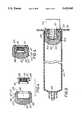
- FIG. 1is an exploded perspective view of the syringe containing a plunger and plunger insert, with plunger rod removed, according to the present invention
- FIG. 2is a longitudinal cross-section of the syringe and plunger taken along the line 2--2 of FIG. 1;
- FIG. 3is a cross-section of the plunger rod taken along the line 2--2 of FIG. 1;
- FIG. 4is an exploded cross-sectional view of the plunger and plunger insert taken along the line 2--2 of FIG. 1;
- FIG. 5is a cross-sectional view of the plunger and plunger insert taken along the line 2--2 of FIG. 1;
- FIG. 6is a fragmentary cross-sectional view of the syringe, plunger, plunger insert and plunger rod taken along the line 2--2 of FIG. 1.
- the syringe of the present inventiongenerally designated 10 comprising:
- syringe 10comprises: a barrel 20 having inside wall 21, a distal end terminating in a tapered tip 22 which has bore 23 therethrough, and a proximal end 24 to receive plunger 30; plunger 30 slideably positioned in barrel 20; and plunger rod 50 is attachable to plunger 30.
- finger hub 26Disposed about the periphery of proximal end 24 of barrel 20 is finger hub 26 which facilitates holding barrel 20 during operation of plunger 30 by exerting a force on plunger rod 50.
- Plunger rod 50having distal end 52 and proximal end 60 comprises handle 62 to facilitate exertion of force on plunger 30 by plunger rod 50 during operation of the syringe.
- Syringe barrel 20is made of an inert gas impermeable material including glass, however, it is preferably made of a substantially transparent material that is somewhat more flexible than glass, such as polyethylene, polypropylene, polystyrenes, acrylic and methacrylic polymers.
- Plunger 30is made of a compressible, elastomeric material, such as polyisoprene rubber.
- Plunger rod 50is made essentially of the same material as the barrel.
- plunger 30is slideably received in barrel 20 and is moved axially in the barrel by a manual force exerted on plunger rod 50 which is engageable with plunger 30.
- Plunger 30 in its relaxed stateresembles an inverted cup having: a distal convex outside face 32; a proximal inside face 34; outside wall 36 contiguous with distal convex outside face 32; inside wall 38 contiguous with inside face 34; and bottom rim 39 which defines the circular opening in the cup shaped plunger 30.
- Distal convex face 32 of plunger 30is to interface with a fluid contained in barrel 20.
- Outside wall 36 of plunger 30comprises: distal ring 40, proximal ring 41, and center ring 42, which are elastically deformable and extend radially outwardly from outside wall 36 and have, when taken together with plunger 30, a minimal diameter slightly in excess of the largest diameter of the working section of barrel 20.
- the ringsform a sealing but slideable engagement with inside wall 21 of barrel 20.
- Inside wall 38, inside face 34, and bottom rim 39define a three-dimensional cavity or area to receive plunger insert 68 of plunger 30.
- Plunger insert 68made of a rigid polymeric material, such as polyethylene, polypropylene, polystyrenes, acrylic and methacrylic polymers comprises: outside wall 74; inside wall 72 having thereon female thread 69 to receive, and engage with, male threads 71 of plunger rod 50; and flange 70.
- Plunger insert 68is located in plunger 36 in such a way that the three-dimensional area defined by inside wall 38, inside face 34, and bottom rim 39 completely embraces plunger insert 68.
- the size of plunger insert 68is such that it does not exert pressure on inside wall 38 so that outside wall of plunger 36 has sufficient space to extend in the lateral direction away from the inside wall of the syringe barrel.
- Flange 70 of plunger insert 68has a diameter that is larger than the diameter of bottom rim 39 of plunger 30 so that plunger insert 68 cannot slip out form plunger 30.
- Plunger rod 50comprises: handle 62 located at proximal end 60 thereof to facilitate exertion of manual force thereon by an operator; distal end 52 having male threads 71 thereon designed to engage female threads 69 of plunger insert 68; shoulder 52; plunger rod tip 64 projecting in the direction of the plunger and extending axially forwardly from the threaded portion to form a protrusion.
- the diameter of said plunger rod tipis substantially smaller than the diameter of the plunger and is designed to contact the proximal inside face 34 at the center portion of plunger 30 upon exertion of pressure on plunger rod 50.
- Plunger 30is inserted into barrel 20 at the proximal end 24 thereof passed finger hub 26 so that barrel 20 may be placed pointing vertically upward with its distal end on a fiat surface, such as a filling line, without interference from plunger 30.
- Barrel 20is filled with the desired liquid, such as a medicament or a diagnostic imaging medium, through bore 23 in tapered tip 22 and capped.
- the liquidcould be pre-sterilized in bulk and filled into the syringe barrel using aseptic technique or the pre-filled syringe may be sterilized by autoclaving or other means at this point.
- the pre-filled, sterilized syringeis then packaged separately from a hypodermic needle and plunger rod to be assembled just prior to use.
- the hypodermic needleis snapped onto the tapered distal end of the barrel.
- Plunger rod 50is threaded into plunger insert 68 contained in the inside cavity of plunger 30 and tightened.
- the practitionerthen gains entry into the desired mammalian site, such as a blood vessel, using conventional venipuncture technique.
- Female threads 69 of plunger insert 68engage male threads 71 of plunger rod 50, and plunger rod tip 64 contacts inside face 34 of plunger 30.
- plunger 30This action causes plunger 30 to extend axially: plunger rod 50 forces plunger insert 68 towards the distal end of plunger 30. Plunger insert 68 is limited in its travel because it is pressed against the inside of bottom rim 39 of plunger 30. This axial extension reduces the diameter of the plunger, which reduces the force required to deliver the liquid from the syringe. Further force reduction is achieved when plunger rod tip 64 is forced towards the distal end of the syringe: the force distorts convex face 32 of plunger 30. The distortion, however, is limited when shoulder 51 of plunger rod 50 contacts bottom rim 39 of plunger 30. This contact between shoulder 51 and bottom rim 39 compresses the proximal end of the plunger and thereby limits the elongation of the plunger during activation.
- plunger rod 50When the operator exerts a relatively slight pressure on plunger rod 50 in a vertical upward direction, the following circumferential deformation of the plunger takes place as shown in FIG. 6: convex face 32 of plunger 30 is extended upward while distal ring 40, proximal ring 41 and center ring 42 are pulled inward by elastic tension forces. This circumferential deformation of the plunger expels head gas from the syringe, i.e. aspirates the syringe. Upon releasing the pressure applied on plunger rod 50, plunger 30 returns to its static position thereby creating a vacuum in barrel 20 and drawing body fluid from the patient indicating that the desired site had been entered and the injection may commence.
- Aspirationmay also be accomplished by pulling the plunger via the plunger rod toward the proximal end of the barrel.
- plunger insert 68exerts force only against bottom rim 39 of plunger 30 and bottom rim 39 becomes the leading edge of plunger 30 during this kind of aspiration.
- the plungeris axially elongated allowing easy manual aspiration.
- plunger rod 50Upon completing the aspiration process, the operator exerts pressure on plunger rod 50. Referring to proximal ring 41, distal ring 40 and center ring 42, it is clear that the force they now exert on the inside wall 21 of barrel 20 is reduced in direct proportion to the rings circumferential deformation. As a result, the plunger moves relatively easily in the barrel allowing convenient delivery of the liquid into the injection site.
- This advantage of the present inventionis even more pronounced when the pre-filled syringe is kept in storage for extended time periods during which time the plunger tends to seize in the barrel and the interfacial force between the plunger and the inside wall of the barrel is extremely difficult to break in the axial direction.
- the force exerted on the plungerpulls the distal, proximal and center rings inwardly and greatly reduces the interfacial force between the plunger and the inside wall of the barrel.
- the syringe of the instant inventionpossesses all the attributes of an ideal syringe for both aspiration and injection as described above. That is, the syringe is simple in construction, thus minimizing the cost of production; it is simple to operate; it is capable of manipulation with one hand; it is capable of multiple self-aspirating actions with each syringe or cartridge; and it is capable of expelling air trapped within the syringe or cartridge either prior to initiation of the self-aspirating action or at any time during the sequence of actions necessary for injection of the syringe content without, on the one hand, precluding self-aspirating action at any point in the sequence or, on the other, rendering the self-aspirating action inoperative.
Landscapes
- Health & Medical Sciences (AREA)
- Vascular Medicine (AREA)
- Engineering & Computer Science (AREA)
- Anesthesiology (AREA)
- Biomedical Technology (AREA)
- Heart & Thoracic Surgery (AREA)
- Hematology (AREA)
- Life Sciences & Earth Sciences (AREA)
- Animal Behavior & Ethology (AREA)
- General Health & Medical Sciences (AREA)
- Public Health (AREA)
- Veterinary Medicine (AREA)
- Infusion, Injection, And Reservoir Apparatuses (AREA)
Abstract
Description
______________________________________ LIST OF REFERENCE NUMBERS USED ______________________________________ Syringe (generally designated) 10Barrel 20 Inside wall ofbarrel 21 Tapered tip of barrel atdistal end 22 Bore through tip ofbarrel 23 Proximal end ofbarrel 24 Finger hub ofbarrel 26Plunger 30 Convex face ofplunger 32 Inside face ofplunger 34 Outside wall ofplunger 36 Inside wall ofplunger 38 Bottom rim ofplunger 39 Distal ring (on outside wall of plunger) 40 Proximal ring (on outside wall of plunger) 41 Center ring (on outside wall of plunger) 42Plunger rod 50 Shoulder ofplunger rod 51 Distal end ofplunger rod 52 Proximal end of plunger rod 60 Handle ofplunger rod 62 Plunger rod tip orprotrusion 64 Neck portion ofplunger rod 66 Plunger insert 68 Female threads on side ofplunger insert 69 Flange ofplunger insert 70 Male threads (on neck portion of plunger rod) 71 Inside wall ofplunger insert 72 Outside wall ofplunger insert 74 Flange on neck portion ofplunger rod 76 ______________________________________
Claims (18)
Priority Applications (16)
| Application Number | Priority Date | Filing Date | Title |
|---|---|---|---|
| US08/239,087US5413563A (en) | 1994-05-06 | 1994-05-06 | Pre-filled syringe having a plunger, plunger insert and plunger rod |
| BR9507625ABR9507625A (en) | 1994-05-06 | 1995-05-01 | Syringe and process of injecting a liquid vehicle into a patient from a syringe |
| CA002189654ACA2189654A1 (en) | 1994-05-06 | 1995-05-01 | Low drag syringe and cartridge |
| HU9603073AHUT76899A (en) | 1994-05-06 | 1995-05-01 | Low drag syringe and cartridge |
| MXPA96005373AMXPA96005373A (en) | 1994-05-06 | 1995-05-01 | Low drag syringe and cartridge. |
| DK95917414TDK0758255T3 (en) | 1994-05-06 | 1995-05-01 | Low resistance syringe |
| FI964451AFI964451L (en) | 1994-05-06 | 1995-05-01 | Low-friction syringe and cartridge |
| PCT/GB1995/000982WO1995030444A1 (en) | 1994-05-06 | 1995-05-01 | Low drag syringe and cartridge |
| JP52875795AJP3665646B2 (en) | 1994-05-06 | 1995-05-01 | Syringe |
| AU23492/95AAU2349295A (en) | 1994-05-06 | 1995-05-01 | Low drag syringe and cartridge |
| CN95193831ACN1152882A (en) | 1994-05-06 | 1995-05-01 | Low-Drag Syringes and Barrels |
| DE69527782TDE69527782T2 (en) | 1994-05-06 | 1995-05-01 | FRICTION-FREE SYRINGE |
| KR1019960706273AKR970702735A (en) | 1994-05-06 | 1995-05-01 | LOW DRAG SYRINGE AND CARTRIDGE |
| EP95917414AEP0758255B1 (en) | 1994-05-06 | 1995-05-01 | Low drag syringe |
| ES95917414TES2184798T3 (en) | 1994-05-06 | 1995-05-01 | SYRINGE OF LOW RESISTANCE. |
| NO964669ANO964669L (en) | 1994-05-06 | 1996-11-05 | Spray and cartridge with little resistance |
Applications Claiming Priority (1)
| Application Number | Priority Date | Filing Date | Title |
|---|---|---|---|
| US08/239,087US5413563A (en) | 1994-05-06 | 1994-05-06 | Pre-filled syringe having a plunger, plunger insert and plunger rod |
Publications (1)
| Publication Number | Publication Date |
|---|---|
| US5413563Atrue US5413563A (en) | 1995-05-09 |
Family
ID=22900548
Family Applications (1)
| Application Number | Title | Priority Date | Filing Date |
|---|---|---|---|
| US08/239,087Expired - LifetimeUS5413563A (en) | 1994-05-06 | 1994-05-06 | Pre-filled syringe having a plunger, plunger insert and plunger rod |
Country Status (1)
| Country | Link |
|---|---|
| US (1) | US5413563A (en) |
Cited By (47)
| Publication number | Priority date | Publication date | Assignee | Title |
|---|---|---|---|---|
| EP1002551A2 (en) | 1998-11-19 | 2000-05-24 | Bracco International B.V. | Easy-slip plunger/plunger rod assembly for a syringe or a cartridge |
| US6319233B1 (en) | 1998-04-17 | 2001-11-20 | Becton, Dickinson And Company | Safety shield system for prefilled syringes |
| US6494866B1 (en) | 2001-04-05 | 2002-12-17 | Owens-Illinois Closure Inc. | Syringe plunger rod and method of manufacture |
| US6497684B2 (en) | 2000-09-27 | 2002-12-24 | Schering Aktiengesellschaft | Syringe with a barrel having a sealing cap to hold a fluid medium within the barrel |
| US20030187406A1 (en)* | 2000-06-15 | 2003-10-02 | Spofforth Leonard Morris | Hypodermic syringe with passive aspiration feature |
| US20040010235A1 (en)* | 2002-07-11 | 2004-01-15 | Weilbacher Eugene E. | Anti-reflux syringe |
| US6679864B2 (en) | 1998-04-17 | 2004-01-20 | Becton Dickinson And Company | Safety shield system for prefilled syringes |
| US6719730B2 (en) | 1998-04-17 | 2004-04-13 | Becton, Dickinson And Company | Safety shield system for prefilled syringes |
| US20040156823A1 (en)* | 1997-08-16 | 2004-08-12 | Julio Reinecke | Syringe for inducing therapeutically-effective proteins |
| US20040236340A1 (en)* | 2001-09-19 | 2004-11-25 | Yves Cirotteau | Device for delivering a biomaterial |
| US20050137533A1 (en)* | 2003-12-17 | 2005-06-23 | Masamichi Sudo | Piston for a syringe and a prefilled syringe using the same |
| US20050251096A1 (en)* | 2004-05-10 | 2005-11-10 | George Armstrong | Syringe assembly with improved cap and luer connector |
| US20060173416A1 (en)* | 2004-11-08 | 2006-08-03 | Young Christopher S | Syringe with coordinated inserts |
| WO2007116086A1 (en)* | 2006-04-12 | 2007-10-18 | Glaxosmithkline Biologicals S.A. | Syringe with sequentially moving plunger flanges |
| US20080082055A1 (en)* | 2006-09-29 | 2008-04-03 | Tyco Healthcare Group Lp | Detachable plunger rod syringe |
| US20090171298A1 (en)* | 2007-12-13 | 2009-07-02 | University Of Victoria Innovation And Development Corporation | Syringe with extendable and retractable needle |
| US20100057014A1 (en)* | 2006-11-16 | 2010-03-04 | CANE' S.P.A. -Socio Unico | Syringe plunger and syringe incorporating the plunger |
| US20110030191A1 (en)* | 2008-04-10 | 2011-02-10 | Primequal S.A. | Method of Manufacturing a Disposable Ejection Device |
| US20110082430A1 (en)* | 2009-10-01 | 2011-04-07 | Conzone Samuel D | Self-lubricating pharmaceutical syringe stoppers |
| EP1917991A4 (en)* | 2005-08-01 | 2011-11-09 | Nipro Corp | Plunger for injector, and syringe and prefilled syringe that use the same |
| US20130218097A1 (en)* | 2002-10-11 | 2013-08-22 | Becton, Dickinson And Company | Flush Syringe Having Compressible Plunger |
| US8530536B2 (en) | 2009-10-01 | 2013-09-10 | Momentive Performance Materials Inc. | Self-lubricating pharmaceutical syringe stoppers |
| US8657793B2 (en) | 2011-09-30 | 2014-02-25 | Becton Dickinson France, S.A.S | Space saving plunger cap and rod assembly |
| US9480797B1 (en) | 2015-10-28 | 2016-11-01 | Bayer Healthcare Llc | System and method for syringe plunger engagement with an injector |
| US9579463B2 (en) | 2013-09-06 | 2017-02-28 | Terumo Kabushiki Kaisha | Barrel for syringe and pre-filled syringe |
| KR20170051488A (en)* | 2014-09-10 | 2017-05-11 | 에스아이오2 메디컬 프로덕츠, 인크. | Three-position plungers, film coated plungers and related syringe assemblies |
| US9694131B2 (en) | 2003-11-25 | 2017-07-04 | Bayer Healthcare Llc | Medical injector system |
| US9744305B2 (en) | 2012-09-28 | 2017-08-29 | Bayer Healthcare Llc | Quick release plunger |
| US9782542B2 (en) | 2009-10-01 | 2017-10-10 | Momentive Performance Materials Inc. | Self-lubricating pharmaceutical syringe stoppers |
| US9844622B2 (en) | 2000-07-10 | 2017-12-19 | Bayer Healthcare Llc | Syringes for medical injector systems |
| US9855390B2 (en) | 2006-03-15 | 2018-01-02 | Bayer Healthcare Llc | Plunger covers and plungers for use in syringes |
| USD847985S1 (en) | 2007-03-14 | 2019-05-07 | Bayer Healthcare Llc | Syringe plunger cover |
| US10279115B2 (en) | 2013-06-06 | 2019-05-07 | Terumo Kabushiki Kaisha | Syringe and prefilled syringe |
| USD870278S1 (en) | 2017-01-13 | 2019-12-17 | Sio2 Medical Products, Inc. | Syringe plunger assembly |
| US10561795B2 (en) | 2013-10-07 | 2020-02-18 | Sio2 Medical Products, Inc. | Convertible plungers, film coated plungers and related syringe assemblies |
| US10765812B2 (en) | 2015-07-14 | 2020-09-08 | Sio2 Medical Products, Inc. | Convertible plungers and methods for assembling the same in a medical barrel |
| US10806852B2 (en) | 2014-03-19 | 2020-10-20 | Bayer Healthcare Llc | System for syringe engagement to an injector |
| US10918800B2 (en) | 2016-05-31 | 2021-02-16 | Sio2 Medical Products, Inc. | Convertible plungers and methods for assembling the same in a medical barrel |
| CN113244487A (en)* | 2016-02-26 | 2021-08-13 | 维斯特医药服务以色列有限公司 | Cartridge for a drug delivery device |
| USD942005S1 (en) | 2007-03-14 | 2022-01-25 | Bayer Healthcare Llc | Orange syringe plunger cover |
| CN114712624A (en)* | 2022-05-11 | 2022-07-08 | 苏州嘉树医疗科技有限公司 | Boosting mechanism suitable for liquid container |
| EP3402555B1 (en) | 2016-01-15 | 2022-11-16 | W. L. Gore & Associates, Inc. | Medical delivery device with laminated stopper |
| USD1002840S1 (en) | 2007-03-14 | 2023-10-24 | Bayer Healthcare Llc | Syringe plunger |
| US11883636B2 (en) | 2018-02-27 | 2024-01-30 | Bayer Healthcare Llc | Syringe plunger engagement mechanism |
| US11969582B2 (en) | 2017-01-06 | 2024-04-30 | Bayer Healthcare Llc | Syringe plunger with dynamic seal |
| US11998718B2 (en) | 2020-06-18 | 2024-06-04 | Bayer Healthcare Llc | System and method for syringe plunger engagement with an injector |
| USD1031029S1 (en) | 2003-11-25 | 2024-06-11 | Bayer Healthcare Llc | Syringe plunger |
Citations (14)
| Publication number | Priority date | Publication date | Assignee | Title |
|---|---|---|---|---|
| US1222424A (en)* | 1916-12-09 | 1917-04-10 | Becton Dickinson Co | Syringe. |
| US1707880A (en)* | 1927-07-22 | 1929-04-02 | John H Sheets | Syringe |
| US3669111A (en)* | 1970-05-20 | 1972-06-13 | Ben B Dubner | Automatic retracting hypodermic syringe |
| US3705582A (en)* | 1969-09-23 | 1972-12-12 | Marvin D Stumpf | Breech loaded syringe and method of breech loading same |
| US3766918A (en)* | 1971-09-07 | 1973-10-23 | J Kessel | Self-aspirating hypodermic ampule |
| US3834387A (en)* | 1972-08-10 | 1974-09-10 | Sherwood Medical Ind Inc | Breech loaded syringe with deformable piston |
| US4216771A (en)* | 1976-12-14 | 1980-08-12 | Sven Arlers | Hypodermic syringe with aspiration effect |
| US4299238A (en)* | 1980-06-24 | 1981-11-10 | Baidwan Balinderjeet S | Vented piston and push-rod subassembly for use in a syringe barrel |
| US4333457A (en)* | 1981-02-09 | 1982-06-08 | Sterling Drug Inc. | Self-aspirating syringe with frictionally engaged locking collet |
| USRE32974E (en)* | 1983-01-23 | 1989-07-04 | Syringe | |
| US4931043A (en)* | 1988-08-08 | 1990-06-05 | Sterling Drug Inc. | Ratchet connector for hypodermic syringe pistons |
| US5009646A (en)* | 1988-03-16 | 1991-04-23 | Daikyo Gomu Seiko Ltd. | Sliding stopper for a syringe |
| US5032114A (en)* | 1987-11-25 | 1991-07-16 | Gudmar Olovson | Syringe |
| US5147328A (en)* | 1989-06-02 | 1992-09-15 | Becton, Dickinson And Company | Syringe assembly |
- 1994
- 1994-05-06USUS08/239,087patent/US5413563A/ennot_activeExpired - Lifetime
Patent Citations (14)
| Publication number | Priority date | Publication date | Assignee | Title |
|---|---|---|---|---|
| US1222424A (en)* | 1916-12-09 | 1917-04-10 | Becton Dickinson Co | Syringe. |
| US1707880A (en)* | 1927-07-22 | 1929-04-02 | John H Sheets | Syringe |
| US3705582A (en)* | 1969-09-23 | 1972-12-12 | Marvin D Stumpf | Breech loaded syringe and method of breech loading same |
| US3669111A (en)* | 1970-05-20 | 1972-06-13 | Ben B Dubner | Automatic retracting hypodermic syringe |
| US3766918A (en)* | 1971-09-07 | 1973-10-23 | J Kessel | Self-aspirating hypodermic ampule |
| US3834387A (en)* | 1972-08-10 | 1974-09-10 | Sherwood Medical Ind Inc | Breech loaded syringe with deformable piston |
| US4216771A (en)* | 1976-12-14 | 1980-08-12 | Sven Arlers | Hypodermic syringe with aspiration effect |
| US4299238A (en)* | 1980-06-24 | 1981-11-10 | Baidwan Balinderjeet S | Vented piston and push-rod subassembly for use in a syringe barrel |
| US4333457A (en)* | 1981-02-09 | 1982-06-08 | Sterling Drug Inc. | Self-aspirating syringe with frictionally engaged locking collet |
| USRE32974E (en)* | 1983-01-23 | 1989-07-04 | Syringe | |
| US5032114A (en)* | 1987-11-25 | 1991-07-16 | Gudmar Olovson | Syringe |
| US5009646A (en)* | 1988-03-16 | 1991-04-23 | Daikyo Gomu Seiko Ltd. | Sliding stopper for a syringe |
| US4931043A (en)* | 1988-08-08 | 1990-06-05 | Sterling Drug Inc. | Ratchet connector for hypodermic syringe pistons |
| US5147328A (en)* | 1989-06-02 | 1992-09-15 | Becton, Dickinson And Company | Syringe assembly |
Cited By (83)
| Publication number | Priority date | Publication date | Assignee | Title |
|---|---|---|---|---|
| US20040156823A1 (en)* | 1997-08-16 | 2004-08-12 | Julio Reinecke | Syringe for inducing therapeutically-effective proteins |
| US7465293B2 (en)* | 1997-08-16 | 2008-12-16 | Orthogen Gentechnologie Gmbh | Syringe for inducing therapeutically-effective proteins |
| US6719730B2 (en) | 1998-04-17 | 2004-04-13 | Becton, Dickinson And Company | Safety shield system for prefilled syringes |
| US6319233B1 (en) | 1998-04-17 | 2001-11-20 | Becton, Dickinson And Company | Safety shield system for prefilled syringes |
| US6626864B2 (en) | 1998-04-17 | 2003-09-30 | Becton Dickinson France, S.A. | Safety shield system for prefilled syringes |
| US20040106905A1 (en)* | 1998-04-17 | 2004-06-03 | Hubert Jansen | Safety shield system for prefilled syringes |
| US6679864B2 (en) | 1998-04-17 | 2004-01-20 | Becton Dickinson And Company | Safety shield system for prefilled syringes |
| US6685676B2 (en) | 1998-04-17 | 2004-02-03 | Becton Dickinson And Company | Safety shield system for prefilled syringes |
| EP1002551A2 (en) | 1998-11-19 | 2000-05-24 | Bracco International B.V. | Easy-slip plunger/plunger rod assembly for a syringe or a cartridge |
| US20030187406A1 (en)* | 2000-06-15 | 2003-10-02 | Spofforth Leonard Morris | Hypodermic syringe with passive aspiration feature |
| US8100865B2 (en)* | 2000-06-15 | 2012-01-24 | Hambley Limited | Hypodermic syringe with passive aspiration feature |
| US9844622B2 (en) | 2000-07-10 | 2017-12-19 | Bayer Healthcare Llc | Syringes for medical injector systems |
| US6497684B2 (en) | 2000-09-27 | 2002-12-24 | Schering Aktiengesellschaft | Syringe with a barrel having a sealing cap to hold a fluid medium within the barrel |
| US6767494B1 (en) | 2001-04-05 | 2004-07-27 | Owens-Illinois Closure Inc. | Method and apparatus for injection molding a threaded syringe plunger rod |
| US6494866B1 (en) | 2001-04-05 | 2002-12-17 | Owens-Illinois Closure Inc. | Syringe plunger rod and method of manufacture |
| US20040236340A1 (en)* | 2001-09-19 | 2004-11-25 | Yves Cirotteau | Device for delivering a biomaterial |
| US7306611B2 (en)* | 2001-09-19 | 2007-12-11 | Bio Holdings International Limited | Device for delivering a biomaterial |
| US20040010235A1 (en)* | 2002-07-11 | 2004-01-15 | Weilbacher Eugene E. | Anti-reflux syringe |
| US9333301B2 (en) | 2002-10-11 | 2016-05-10 | Becton, Dickinson And Company | Flush syringe having compressible plunger |
| US8882724B2 (en)* | 2002-10-11 | 2014-11-11 | Becton, Dickinson And Company | Flush syringe having compressible plunger |
| US20130218097A1 (en)* | 2002-10-11 | 2013-08-22 | Becton, Dickinson And Company | Flush Syringe Having Compressible Plunger |
| US9694131B2 (en) | 2003-11-25 | 2017-07-04 | Bayer Healthcare Llc | Medical injector system |
| US11596735B2 (en) | 2003-11-25 | 2023-03-07 | Bayer Healthcare Llc | Medical injector system |
| US10894124B2 (en) | 2003-11-25 | 2021-01-19 | Bayer Healthcare Llc | Medical injector system |
| USD1031029S1 (en) | 2003-11-25 | 2024-06-11 | Bayer Healthcare Llc | Syringe plunger |
| US10434249B2 (en) | 2003-11-25 | 2019-10-08 | Bayer Healthcare Llc | Medical injector system |
| US7927315B2 (en)* | 2003-12-17 | 2011-04-19 | Daikyo Seiko, Ltd. | Piston for a syringe and a prefilled syringe using the same |
| US20050137533A1 (en)* | 2003-12-17 | 2005-06-23 | Masamichi Sudo | Piston for a syringe and a prefilled syringe using the same |
| WO2005113038A3 (en)* | 2004-05-10 | 2006-09-28 | Bracco Diagnostics Inc | Syringe assembly with improved cap and luer connector |
| US20050251096A1 (en)* | 2004-05-10 | 2005-11-10 | George Armstrong | Syringe assembly with improved cap and luer connector |
| US20060173416A1 (en)* | 2004-11-08 | 2006-08-03 | Young Christopher S | Syringe with coordinated inserts |
| EP1917991A4 (en)* | 2005-08-01 | 2011-11-09 | Nipro Corp | Plunger for injector, and syringe and prefilled syringe that use the same |
| US10668221B2 (en) | 2006-03-15 | 2020-06-02 | Bayer Healthcare Llc | Plunger covers and plungers for use in syringes |
| US9855390B2 (en) | 2006-03-15 | 2018-01-02 | Bayer Healthcare Llc | Plunger covers and plungers for use in syringes |
| US20100016807A1 (en)* | 2006-04-12 | 2010-01-21 | Jacques Thilly | Syringe with Sequentially Moving Plunger Flanges |
| WO2007116086A1 (en)* | 2006-04-12 | 2007-10-18 | Glaxosmithkline Biologicals S.A. | Syringe with sequentially moving plunger flanges |
| US8038656B2 (en) | 2006-09-29 | 2011-10-18 | Tyco Healthcare Group Lp | Detachable plunger rod syringe |
| US20080082055A1 (en)* | 2006-09-29 | 2008-04-03 | Tyco Healthcare Group Lp | Detachable plunger rod syringe |
| US8172814B2 (en)* | 2006-11-16 | 2012-05-08 | Cane' S.P.A. | Syringe plunger and syringe incorporating the plunger |
| US20100057014A1 (en)* | 2006-11-16 | 2010-03-04 | CANE' S.P.A. -Socio Unico | Syringe plunger and syringe incorporating the plunger |
| USD942005S1 (en) | 2007-03-14 | 2022-01-25 | Bayer Healthcare Llc | Orange syringe plunger cover |
| USD1002840S1 (en) | 2007-03-14 | 2023-10-24 | Bayer Healthcare Llc | Syringe plunger |
| USD1030052S1 (en) | 2007-03-14 | 2024-06-04 | Bayer Healthcare Llc | Syringe plunger |
| USD1030051S1 (en) | 2007-03-14 | 2024-06-04 | Bayer Healthcare Llc | Syringe plunger |
| USD847985S1 (en) | 2007-03-14 | 2019-05-07 | Bayer Healthcare Llc | Syringe plunger cover |
| US20090171298A1 (en)* | 2007-12-13 | 2009-07-02 | University Of Victoria Innovation And Development Corporation | Syringe with extendable and retractable needle |
| US9138544B2 (en)* | 2008-04-10 | 2015-09-22 | Primequal S.A. | Method of manufacturing a disposable ejection device |
| US20110030191A1 (en)* | 2008-04-10 | 2011-02-10 | Primequal S.A. | Method of Manufacturing a Disposable Ejection Device |
| CN101980735A (en)* | 2008-04-10 | 2011-02-23 | 普里姆奎尔股份有限公司 | Method of manufacturing a disposable ejection device |
| JP2011516194A (en)* | 2008-04-10 | 2011-05-26 | プリメクアル・エス・アー | Method for manufacturing a disposable discharge device |
| US8618185B2 (en) | 2009-10-01 | 2013-12-31 | Momentive Performance Materials Inc. | Self-lubricating pharmaceutical syringe stoppers |
| US9782542B2 (en) | 2009-10-01 | 2017-10-10 | Momentive Performance Materials Inc. | Self-lubricating pharmaceutical syringe stoppers |
| US20110082430A1 (en)* | 2009-10-01 | 2011-04-07 | Conzone Samuel D | Self-lubricating pharmaceutical syringe stoppers |
| US8530536B2 (en) | 2009-10-01 | 2013-09-10 | Momentive Performance Materials Inc. | Self-lubricating pharmaceutical syringe stoppers |
| US8657793B2 (en) | 2011-09-30 | 2014-02-25 | Becton Dickinson France, S.A.S | Space saving plunger cap and rod assembly |
| US9744305B2 (en) | 2012-09-28 | 2017-08-29 | Bayer Healthcare Llc | Quick release plunger |
| US10286152B2 (en) | 2012-09-28 | 2019-05-14 | Bayer Healthcare Llc | Quick release plunger |
| US10279115B2 (en) | 2013-06-06 | 2019-05-07 | Terumo Kabushiki Kaisha | Syringe and prefilled syringe |
| US11045606B2 (en) | 2013-06-06 | 2021-06-29 | Terumo Kabushikikaisha | Syringe and prefilled syringe |
| US9579463B2 (en) | 2013-09-06 | 2017-02-28 | Terumo Kabushiki Kaisha | Barrel for syringe and pre-filled syringe |
| US10561795B2 (en) | 2013-10-07 | 2020-02-18 | Sio2 Medical Products, Inc. | Convertible plungers, film coated plungers and related syringe assemblies |
| US11103637B2 (en) | 2014-03-19 | 2021-08-31 | Bayer Healthcare Llc | System for syringe engagement to an injector |
| US11383029B2 (en) | 2014-03-19 | 2022-07-12 | Bayer Healthcare Llc | System for syringe engagement to an injector |
| US10806852B2 (en) | 2014-03-19 | 2020-10-20 | Bayer Healthcare Llc | System for syringe engagement to an injector |
| US10850042B2 (en)* | 2014-09-10 | 2020-12-01 | Sio2 Medical Products, Inc. | Three-position plungers, film coated plungers and related syringe assemblies |
| KR20170051488A (en)* | 2014-09-10 | 2017-05-11 | 에스아이오2 메디컬 프로덕츠, 인크. | Three-position plungers, film coated plungers and related syringe assemblies |
| US20170296756A1 (en)* | 2014-09-10 | 2017-10-19 | Sio2 Medical Products, Inc. | Three-position plungers, film coated plungers and related syringe assemblies |
| AU2020201401B2 (en)* | 2014-09-10 | 2021-12-23 | Sio2 Medical Products, Llc | Three-position plungers, film coated plungers and related syringe assemblies |
| US11857771B2 (en) | 2014-09-10 | 2024-01-02 | Sio2 Medical Products, Inc. | Three-position plungers, film coated plungers and related syringe assemblies |
| US10765812B2 (en) | 2015-07-14 | 2020-09-08 | Sio2 Medical Products, Inc. | Convertible plungers and methods for assembling the same in a medical barrel |
| US10512721B2 (en) | 2015-10-28 | 2019-12-24 | Bayer Healthcare Llc | System and method for syringe plunger engagement with an injector |
| US11547794B2 (en) | 2015-10-28 | 2023-01-10 | Bayer Healthcare Llc | System and method for syringe plunger engagement with an injector |
| US9480797B1 (en) | 2015-10-28 | 2016-11-01 | Bayer Healthcare Llc | System and method for syringe plunger engagement with an injector |
| US12102793B2 (en) | 2015-10-28 | 2024-10-01 | Bayer Healthcare Llc | System and method for syringe plunger engagement with an injector |
| EP3402555B1 (en) | 2016-01-15 | 2022-11-16 | W. L. Gore & Associates, Inc. | Medical delivery device with laminated stopper |
| CN113244487A (en)* | 2016-02-26 | 2021-08-13 | 维斯特医药服务以色列有限公司 | Cartridge for a drug delivery device |
| US10918800B2 (en) | 2016-05-31 | 2021-02-16 | Sio2 Medical Products, Inc. | Convertible plungers and methods for assembling the same in a medical barrel |
| US11896807B2 (en) | 2016-05-31 | 2024-02-13 | Sio2 Material Products, Inc | Convertible plungers and methods for assembling the same in a medical barrel |
| US11969582B2 (en) | 2017-01-06 | 2024-04-30 | Bayer Healthcare Llc | Syringe plunger with dynamic seal |
| USD870278S1 (en) | 2017-01-13 | 2019-12-17 | Sio2 Medical Products, Inc. | Syringe plunger assembly |
| US11883636B2 (en) | 2018-02-27 | 2024-01-30 | Bayer Healthcare Llc | Syringe plunger engagement mechanism |
| US11998718B2 (en) | 2020-06-18 | 2024-06-04 | Bayer Healthcare Llc | System and method for syringe plunger engagement with an injector |
| CN114712624A (en)* | 2022-05-11 | 2022-07-08 | 苏州嘉树医疗科技有限公司 | Boosting mechanism suitable for liquid container |
Similar Documents
| Publication | Publication Date | Title |
|---|---|---|
| US5413563A (en) | Pre-filled syringe having a plunger, plunger insert and plunger rod | |
| US5411488A (en) | Pre-filled syringe and pre-filled cartridge having an improved plunger and plunger rod for reducing syringing force | |
| US5411489A (en) | Pre-filled syringe and pre-filled cartridge having actuating cylinder/plunger rod combination for reducing syringing force | |
| EP0758255B1 (en) | Low drag syringe | |
| EP0635278B1 (en) | - Self-aspirating syringe or cartridge having an aspirating plunger | |
| EP1002551A2 (en) | Easy-slip plunger/plunger rod assembly for a syringe or a cartridge | |
| US6213985B1 (en) | Tapered syringe barrel with tapered plunger | |
| US4543093A (en) | Variable sealing pressure plunger rod assembly | |
| US4500310A (en) | Variable sealing pressure plunger rod assembly | |
| JP3083134B2 (en) | Cannula sealed shield assembly | |
| EP0925798B1 (en) | Easy-slip plunger/plunger rod assembly for a syringe or a cartridge | |
| US6749590B2 (en) | Syringe barrel and plunger assembly having ellipsoidal configurations | |
| CA2539813C (en) | Flush syringe having anti-reflux features | |
| EP0847770B1 (en) | Prefilled syringe | |
| US5314416A (en) | Low friction syring assembly | |
| EP0781567B1 (en) | Prefilled syringe | |
| US6681810B2 (en) | Filling device for a needleless injector cartridge | |
| US6610042B2 (en) | Disposable unit-dose jet-injection syringe for pre-filled and/or transfilled liquid injectable medical drug or vaccine products and method thereof | |
| US5413564A (en) | Predetermined dosage hypodermic syringe system |
Legal Events
| Date | Code | Title | Description |
|---|---|---|---|
| AS | Assignment | Owner name:STERLING WINTHROP INC., NEW YORK Free format text:ASSIGNMENT OF ASSIGNORS INTEREST;ASSIGNORS:BASILE, PETER A.;BROWN, SCOTT C.;SNYDER, FRED E.;AND OTHERS;REEL/FRAME:007003/0553 Effective date:19940505 | |
| STCF | Information on status: patent grant | Free format text:PATENTED CASE | |
| AS | Assignment | Owner name:NYCOMED IMAGING AS, NORWAY Free format text:ASSIGNMENT OF ASSIGNORS INTEREST;ASSIGNOR:STERLING WINTHROP INC.;REEL/FRAME:008709/0922 Effective date:19950413 | |
| FPAY | Fee payment | Year of fee payment:4 | |
| FPAY | Fee payment | Year of fee payment:8 | |
| AS | Assignment | Owner name:GE HEALTHCARE AS,NORWAY Free format text:CHANGE OF NAME;ASSIGNORS:AMERSHAM HEALTH AS;NYCOMED IMAGING AS;REEL/FRAME:018039/0537 Effective date:20060329 Owner name:GE HEALTHCARE AS, NORWAY Free format text:CHANGE OF NAME;ASSIGNORS:AMERSHAM HEALTH AS;NYCOMED IMAGING AS;REEL/FRAME:018039/0537 Effective date:20060329 | |
| FPAY | Fee payment | Year of fee payment:12 |