US5413454A - Mobile robotic arm - Google Patents
Mobile robotic armDownload PDFInfo
- Publication number
- US5413454A US5413454AUS08/089,016US8901693AUS5413454AUS 5413454 AUS5413454 AUS 5413454AUS 8901693 AUS8901693 AUS 8901693AUS 5413454 AUS5413454 AUS 5413454A
- Authority
- US
- United States
- Prior art keywords
- arm
- base
- mid
- lower arm
- gripper
- Prior art date
- Legal status (The legal status is an assumption and is not a legal conclusion. Google has not performed a legal analysis and makes no representation as to the accuracy of the status listed.)
- Expired - Fee Related
Links
Images


Classifications
- B—PERFORMING OPERATIONS; TRANSPORTING
- B25—HAND TOOLS; PORTABLE POWER-DRIVEN TOOLS; MANIPULATORS
- B25J—MANIPULATORS; CHAMBERS PROVIDED WITH MANIPULATION DEVICES
- B25J9/00—Programme-controlled manipulators
- B25J9/02—Programme-controlled manipulators characterised by movement of the arms, e.g. cartesian coordinate type
- B25J9/04—Programme-controlled manipulators characterised by movement of the arms, e.g. cartesian coordinate type by rotating at least one arm, excluding the head movement itself, e.g. cylindrical coordinate type or polar coordinate type
- B25J9/046—Revolute coordinate type
- B—PERFORMING OPERATIONS; TRANSPORTING
- B25—HAND TOOLS; PORTABLE POWER-DRIVEN TOOLS; MANIPULATORS
- B25J—MANIPULATORS; CHAMBERS PROVIDED WITH MANIPULATION DEVICES
- B25J5/00—Manipulators mounted on wheels or on carriages
- B25J5/007—Manipulators mounted on wheels or on carriages mounted on wheels
Definitions
- the present inventionrelates generally to robotic equipment, and more particularly to a mobile robotic arm for grasping objects at low-level, intermediate level, and high reach areas of a domestic dwelling.
- the present inventionaddresses the aforementioned difficulties typically encountered by individuals confined to wheelchairs by providing a mobile robotic arm which is specifically designed to grasp objects at low-level, intermediate level and high reach areas of a domestic dwelling.
- a mobile robotic armwhich is specifically designed to grasp objects at low-level, intermediate level and high reach areas of a domestic dwelling.
- many types of robotsare currently known, the vast majority of these robots have been developed for specific industrial applications and are not suited for use within a domestic dwelling. Additionally, those robots which can be placed within a home are usually novelty items and not designed to provide access to low-level, intermediate level, and high reach areas.
- a mobile robotic armfor grasping objects at low-level, intermediate level and high reach areas of a domestic dwelling.
- the mobile robotic armgenerally comprises a mobile base having a robotic arm connected thereto which is movable between a collapsed position and various extended positions.
- the robotic armis releasably connected to the base so that it may be easily and quickly removed for maintenance purposes.
- the robotic armitself comprises an elongate lower arm which is rotatably and pivotally connected to the base in a manner wherein the lower arm is selectively articulable to angled orientations of approximately 0 degrees to 90 degrees relative the base.
- Nested within the lower armis an elongate mid-arm which is pivotally connected to the lower arm in a manner wherein the mid-arm is selectively articulable to angled orientations of approximately 0 degrees to 180 degrees relative the lower arm.
- Nested within the mid-armis an elongate forearm which is pivotally connected to the mid-arm such that the forearm is selectively articulable to angled orientations of approximately 0 degrees to 270 degrees relative the mid-arm.
- the forearmcomprises a frame member having one end pivotally connected to the mid-arm. Slidably connected to the frame member is a carriage member which is selectively extensible and retractable relative the frame member when the forearm is not nested within the mid-arm.
- a gripperis rotatably connected to one end of the carriage member for selectively grasping and releasing household objects.
- the grippercomprises a pair of gripper jaws which are moveable between open and closed positions, the gripper jaws being adapted to conform to the shape of the particular object grasped thereby.
- the mobile robotic arm of the present inventionfurther comprises a controller which is electrically configured to independently control the various movements of the base and the robotic arm. Particularly, the controller regulates the rolling movement of the base, the rotation of the lower arm relative the base, the pivotal movement of the lower arm relative the base, the pivotal movement of the mid-arm relative the lower arm, the pivotal movement of the forearm relative the mid-arm, the extension and retraction of the carriage member, the rotation of the gripper, and the opening and the closing of the gripper jaws.
- the controllermay further include a video display screen thereon for displaying images generated by a video camera attached to the base, thereby allowing the user to monitor the movements of the base and robotic arm without necessarily being in the same room in which the arm is being utilized.
- both the base and armare powered by a rechargeable battery disposed within the base.
- the armis preferably configured to reach to a height of approximately 8 feet when fully extended. Due to this extension capability, the user is provided access to virtually all areas within the dwelling. Additionally, the controller is configured to be easily and quickly attachable to an arm rest portion of a conventional wheelchair.
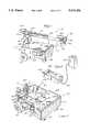
- FIG. 1is a perspective view of the mobile robotic arm of the present invention
- FIG. 2is a perspective view of a controller used in conjunction with the present invention
- FIG. 3is a perspective view of the mobile base comprising the mobile robotic arm
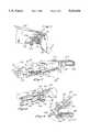
- FIG. 4is a perspective view illustrating the robotic arm in a partially extended orientation
- FIG. 5is a partial perspective view of the lower arm component of the robotic arm taken along line 5--5 of FIG. 4;
- FIG. 6is a partial perspective view of the mid-arm component of the robotic arm taken along line 6--6 of FIG. 4;
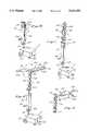
- FIG. 7is a partial perspective view of the forearm component of the robotic arm taken along line 7--7 of FIG. 4;
- FIG. 8is a perspective view of the gripper drive assembly disposed within the forearm component of the robotic arm taken along line 8--8 of FIG. 7;
- FIG. 9is a partial perspective view of the gripper of the robotic arm taken along line 9--9 of FIG. 8;
- FIG. 10is a perspective view illustrating the movement of the lower arm component relative the base
- FIG. 11is a perspective view illustrating the movement of the mid-arm component relative the lower arm component
- FIG. 12is a perspective view illustrating the movement of the forearm component relative the mid-arm component
- FIG. 13is a perspective view illustrating the movements of a carriage member comprising the forearm component and gripper attached to the carriage member;
- FIG. 14is a perspective view illustrating the robotic arm as oriented to grasp objects stored at low-level areas.
- FIG. 1perspectively illustrates the mobile robotic arm 10 constructed in accordance with the preferred embodiment of the present invention.
- mobile robotic arm 10generally comprises a mobile base 12 having a robotic arm 14 connected thereto.
- base 12generally comprises a frame 16 having a generally rectangular configuration and defining two longitudinal sides and two lateral sides.
- Frame 16is preferably constructed from stainless steel though other materials may be utilized as an alternative.
- a battery 18Disposed within the frame 16 is a battery 18 which is used to provide power to the various motors disposed within the base 12 and arm 14.
- the battery 18is rechargeable and adapted to have a charge capacity substantially equivalent to batteries used in conjunction with conventionally known, electrically powered wheelchairs.
- Extending outwardly from each of the longitudinal sides of the frame 16are drive wheels 20, each of which are independently driven by a respective drive motor 22 electrically interfaced to battery 18.
- guide wheels 24Disposed adjacent the lateral side 16a of frame 16 which is furthest from drive wheels 20 are guide wheels 24.
- guide wheels 24are rotatably connected to frame 16 thereby aiding in the maneuverability of the mobile robotic arm 10 throughout the various rooms of the domestic dwelling.
- Attached to the outer surface of the lateral side 16a and portions of the longitudinal sides of frame 16is a continuous layer of cushioning material 26.
- cushioning material 26is used to prevent damage to any walls or other objects within the dwelling when the mobile robotic arm 10 is inadvertently caused to collide with such walls or objects.
- a central processor 28which is used to transmit signals to the various components comprising the mobile robotic arm 10 in a manner which will be described in greater detail below.
- the robotic arm 14is rotatably connected to the mobile base 12 via a shaft member 30.
- shaft member 30is rotatably interfaced to the frame 16 of base 12 through the utilization of a bracket 32 which is rigidly attached to the lateral side 16b of frame 16 adjacent the drive wheels 20.
- bracket 32Disposed within bracket 32 is a bearing 34 into which shaft member 30 is rotatably received.
- the lower end of shaft member 30is rigidly connected to a downwardly extending second shaft 36 having a diameter slightly less than the diameter of shaft member 30.
- Second shaft 36extends through one end of and is rigidly attached to an elongate lever member 38.
- lever member 38The end of lever member 38 opposite that attached to second shaft 36 is pivotally interfaced to a rod 40 which extends outwardly from a lead screw actuator 42.
- Lead screw actuator 42is driven by a motor 44 attached adjacent the end thereof opposite that connected to lever member 38 and is operable to reciprocally actuate rod 40.
- the outward actuation of rod 40is operable to pivot lever member 38 in a direction toward the lateral side 16b of frame 16. Due to the rigid attachment of lever member 38 to second shaft 36, such actuation of lever member 38 toward the lateral side 16b causes shaft member 30 to rotate in the direction designated by the arrow shown in FIG. 3, i.e. a clockwise direction.
- inward actuation of the rod 40causes the lever member 38 to pivot in a direction toward the lead screw actuator 42, thus causing the shaft member 30 to rotate in a counterclockwise direction.
- the stroke of rod 40is specifically limited such that the shaft member 30 may rotate a maximum of ⁇ 20 degrees relative a horizontal axis A--A extending through base 12. The purpose of such limited rotation will be explained in greater detail below.
- the lever member 38must be pivoted to a position by the rod 40 which extends beyond the inner surface of lateral side 16b of the frame 16.
- an elongate opening 46is provided within the lateral side 16b to provide clearance for the lever member 38 when such is pivoted outwardly by the outward actuation of rod 40.
- lead screw actuator 42 and rod 40are used to selectively pivot lever member 38 and hence rotate shaft member 30, it will be appreciate that other devices such as pneumatically or hydraulically actuated cylinders may be utilized as an alternative.
- the lead screw actuator 42, motor 44, lever member 38, and second shaft 36are all preferably disposed within the frame 16.
- These components, in addition to the battery 18, central processor 28, and motors 22are preferably enclosed within the frame 16 by a sheet 48 rigidly attached to the upper surface thereof. Attached to the outer surface of one of the longitudinal sides of frame 16 is a video camera 50. The use of video camera 50 will be explained in greater detail below.
- robotic arm 14generally comprises a lower arm component 52, a mid-arm component 54, and a forearm component 56, all of which are pivotally interconnected.
- robotic arm 14is connected to mobile base 12 through the attachment of the elongate lower arm 52 to the upper end of the shaft member 30.
- lower arm 52is pivotally connected to shaft member 30 via a bracket 58 disposed upon the upper end of shaft member 30.
- bracket 58serves to directly interface lower arm 52 to shaft member 30, the rotation of shaft member 30 will cause the concurrent rotation of the lower arm 52 and hence the robotic arm 14.
- lower arm 52is selectively articulable to angled orientations of approximately 0 degrees to 90 degrees relative the axis A--A extending through base 12.
- lower arm 52assumes an angled orientation of approximately 0 degrees relative axis A--A as seen in FIG. 1.
- FIGS. 4 and 10-12When angled at 90 degrees relative axis A--A, lower arm 52 assumes the orientation seen in FIGS. 4 and 10-12, while FIG. 14 illustrates lower arm 52 in an angled orientation between 0 degrees and 90 degrees.
- a lead screw actuator 62having a rod 63 extending therefrom.
- Lead screw actuator 62is driven by a motor 64 disposed on one end thereof. As best seen in FIG. 4, the end of lead screw actuator 62 adjacent motor 64 is pivotally connected to an extension 66 extending angularly upwardly from bracket 58, with the distal end of rod 63 being pivotally connected to a mount 68 rigidly attached to the mid-portion of lower arm 52.
- rod 63is actuated outwardly, i.e. away from motor 64, lower arm 52 is caused to move angularly downward toward base 12.
- lower arm 52will be oriented at approximately 0 degrees relative axis A--A.
- rod 63is actuated inwardly, i.e. toward motor 64
- lower arm 52is caused to move angularly upward away from base 12.
- rod 63when rod 63 reaches its full inward stroke, lower arm 52 will be angularly oriented at approximately 90 degrees relative axis A--A.
- mid-arm 54Pivotally connected to the end of lower arm 52 opposite that connected to bracket 58 is the mid-arm 54. Such pivotal connection is facilitated by a pivot pin 70 which interconnects lower arm 52 and mid-arm 54.
- mid-arm 54is sized and configured so as to be nestable within lower arm 52.
- pivot pin 70allows mid-arm 54 to be selectively articulable to angled orientations of approximately 0 degrees to 180 degrees relative an axis B--B extending longitudinally through lower arm 52.
- Motor 74includes a drive shaft 76 extending outwardly therefrom which terminates at its distal end with a sprocket 78.
- a mount 80rigidly attached to and extending from lower arm 52 is a shaft 82 which, like shaft 76, has a sprocket 84 disposed on its distal end.
- a worm gear 86disposed upon shaft 82 between mount 80 and sprocket 84 is a worm gear 86.
- Worm gear 86is oriented upon shaft 82 so as to cooperate with a gear 88 disposed upon and rigidly attached to the central portion of pivot pin 70.
- sprockets 78 and 84are oriented relative lower arm 52 so as to be interconnectable by a drive chain 90 such that rotation of the drive shaft 76 via the motor 74 will cause a subsequent rotation of the worm gear 86 and hence the gear 88.
- pivot pinis rotatably interfaced to lower arm 52 but rigidly secured to mid-arm 54. As such, as gear 88 rotates due to the rotation of worm gear 86, pivot pin 70 will rotate within lower arm 52 and cause the movement of mid-arm 54 due to its rigid connection thereto.
- forearm 56Pivotally connected to the end of mid-arm 54 opposite that connected to lower arm 52 is the forearm 56.
- forearm 56is sized and configured to be nestable within mid-arm 54.
- mid-arm 54may be removed from is nested orientation within lower arm 52 with forearm 56 remaining nested within mid-arm 54.
- forearm 56comprises a frame member 92 having a carriage member 94 slidably mounted thereto.
- the pivotal connection between forearm 56 and mid-arm 54is facilitated by a pivot pin 96 which is used to interconnect one end of frame member 92 to mid-arm 54.
- a pivot pin 96which is used to interconnect one end of frame member 92 to mid-arm 54.
- pivot pin 96the pivotal connection of forearm 56 to mid-arm 54 facilitated by pivot pin 96 allows forearm 56 to be selectively articulable to angled orientations of approximately 0 degrees to 270 degrees relative an axis C--C extending longitudinally through mid-arm 54.
- a mount 98attached to mid-arm 54 via a mount 98 is a motor 100.
- Extending outwardly from the motor 100is a shaft 102 having a gear 104 disposed on the distal end thereof.
- Gear 104is cooperatively engaged to a gear 106 which is disposed on the distal end of a shaft 108 rotatably connected to the end of mid-arm 54 attached to frame member 92.
- pivot pin 96Disposed upon the mid-portion of shaft 108 is a worm gear 110 which is cooperatively engaged to a gear 112 disposed upon and rigidly attached to the mid-portion of pivot pin 96.
- pivot pin 96is rotatably interfaced to mid-arm 54 with the opposed ends thereof being rigidly connected to frame member 92 of forearm 56. As such, the rotation of pivot pin 96 via the rotation of gear 112 will cause the corresponding movement of forearm 56.
- carriage member 94is slidably interfaced to frame member 92. Particularly, carriage member 94 is received into a correspondingly shaped channel member 114 rigidly secured to frame member 92.
- carriage member 94is selectively extensible and retractable relative frame member 92 and channel member 114 along an axis D--D which extends longitudinally through frame member 92.
- a lead screw actuator 116which is driven by a motor 118 interfaced thereto and includes a rod 119 extending therefrom.
- the end of lead screw actuator 116 adjacent motor 118is rigidly connected to frame member 92 with the distal end of rod 119 being attached to carriage member 94.
- carriage member 94As seen in FIG. 7, as rod 119 is actuated outwardly, i.e. away from motor 118, carriage member 94 is likewise caused to move outwardly. Conversely, as rod 119 is actuated inwardly, i.e. toward motor 118, carriage member 94 is likewise caused to move inwardly. As previously indicated, carriage member 94 moves in a direction parallel to the axis D--D extending longitudinally through frame member 92.
- gripper assembly 120attached to forearm 56 on the end opposite that pivotally connected to mid-arm 54 is a gripper assembly 120.
- gripper assembly 120generally comprises a gripper base 122 having a pair of gripper jaws 124 extending outwardly therefrom.
- each of gripper jaws 124is adapted to conform to the shape of the object to be grasped by the gripper assembly 120.
- each of the gripper jaws 124generally comprises a flexible band 126 having a plurality of gripper pads 128 attached thereto. The object contacting surfaces of the gripper pads 128 preferably have a serrated configuration to aid their gripping characteristics.
- the gripper jaws 124are moveable between a grasping position, shown in FIG. 7, and a releasing position, shown in FIG. 9.
- a grasping positionshown in FIG. 7
- a releasing positionshown in FIG. 9.
- attached to the ends of the gripper jaws 124 connected to the base 122are pairs of roller members 130.
- each of the pairs of roller members 130are interfaced to a cam member 132 disposed on the distal end of a rod 134 extending from a lead screw actuator 135.
- the distal end of the rod 134 and cam member 132are disposed within the gripper base 122.
- lead screw actuator 135opposite that connected to cam member 132 is secured within the interior of carriage member 134 and is driven by a motor 136 attached immediately adjacent thereto.
- Gripper base 122is attached to carriage member 94 via a bearing 138 which allows base 122 to be rotated relative carriage member 134 but prevents any other movement of base 122 from occurring.
- rod 134is actuated outwardly, i.e. away from motor 136
- cam member 132is forced between the pairs of roller members 130 thereby causing the gripper jaws 124 to assume the releasing position shown in FIG. 9.
- rod 134is actuated inwardly, i.e.
- the cam member 132is pulled from between roller members 130 thereby causing the gripper jaws 124 to assume the grasping position shown in FIG. 7.
- the gripper jaws 124are normally biased toward the grasping position by the action of the flexible bands 126 which are rigidly secured to the gripper base 122.
- bearing 138is adapted to allow gripper base 122 and hence jaws 124 to be rotated relative carriage member 94.
- gear 140disposed on the end of bearing 138 opposite that connected to base 122 is a gear 140 through which rod 134 extends.
- Gear 140is cooperatively engaged to a gear 142 disposed on the distal end of a shaft 144 extending outwardly from a motor 146 which is secured within the interior of carriage member 94.
- the rotation of shaft 144 via motor 146will cause the subsequent rotation of the base member 122 as seen in FIG. 8.
- rod 134extends through but is not attached to gear 140, base 122 and gripper jaws 124 may be rotated irrespective of whether the gripper jaws 124 are in the grasping position or releasing position.
- the mobile robotic arm 10 of the present inventionfurther comprises a control box 148 for controlling the various movements of the mobile base 12 and robotic arm 14.
- Control box 148is interfaced to a transmitter 150 via a wire 152.
- the movements of the base 12 and robotic arm 14are controlled via radio waves which emanate from transmitter 152.
- control box 148is sized and configured to be interfaced to the arm rest portion of a conventional wheelchair. As such, the control box 148 is adapted to be easily accessible to the wheel chair occupant for purposes of controlling the movements of the base 12 and robotic arm 14.
- the central processor 28 disposed within base 12is adapted to receive the radio transmissions from transmitter 152 and to convert such transmissions to electrical signals which are operable to control the various movements of the mobile robotic arm 10.
- Disposed upon an outer surface of control box 148are an on/off switch 154, a control lever 156, and a plurality of switches 158. The particular movements of the robotic arm 14 are controlled through the manipulation of the control lever 156 in conjunction with the selective actuation of the switches 158.
- control box 148is electrically configured to independently control the rolling movement of the base 12, the rotation of the lower arm 52 relative the base 12, the pivotal movement of the lower arm 52 relative the base 12, the pivotal movement of the mid-arm 54 relative the lower arm 52, the pivotal movement of the forearm 56 relative the mid-arm 54, the extension and retraction of the carriage member 94 relative frame member 92, the rotation of the gripper base 122 and the opening and closing of the gripper jaws 124.
- control box 148may further include a video display screen thereon for receiving video transmissions generated by the video camera 50 attached to the base 12.
- the usermay operate the mobile robotic arm 10 in locations remote from the user.
- the mobile robotic arm 10 of the present inventionis adapted to grasp objects at low-level, intermediate level and high reach areas of a domestic dwelling.
- the control arm 14assumes the position shown in FIG. 1.
- the robotic arm 14assumes a position similar to that as shown in FIG. 14.
- the robotic arm 14assumes an orientation similar to that shown in FIG. 4.
- the robotic arm 14assumes a position similar to that shown in FIG. 12.
- the robotic arm 14is adapted to extend vertically upwardly a height not exceeding approximately eight feet as measured from the top of frame 16 to the distal ends of the gripper jaws 124.
- robotic arm 14is able to obtain access to virtually all areas within the domestic dwelling. Due to the nesting of the forearm 56 within mid-arm 54 and mid-arm 54 within lower arm 52, when robotic arm 14 is disposed in the retracted position shown in FIG. 1, a minimum amount of space is occupied thereby. As previously specified, robotic arm 14 is preferably limited to ⁇ 20 degrees rotation relative axis A--A extending through base 12. In this regard, due to the extension capacity of arm 14, if the rotation thereof were to exceed the aforementioned limits, base 12 would be prone to tip on one of its longitudinal sides due to the moment created by the weight of the arm 14 when horizontally extended.
- Each of the motors utilized in conjunction with the mobile robotic arm 10 of the present inventionare powered by the rechargeable battery 18 disposed within the base 12. Power is transmitted from the battery 18 to the various motors via an electrical line 160 as seen in FIGS. 1 and 4. It will be appreciated that as an alternative to the various lead screw actuators and motors utilized in conjunction with the mobile robotic arm 10 of the present invention, components such as hydraulically or pneumatically actuated cylinders may be used to facilitate the various movements of the components.
Landscapes
- Engineering & Computer Science (AREA)
- Robotics (AREA)
- Mechanical Engineering (AREA)
- Manipulator (AREA)
Abstract
Description
The present invention relates generally to robotic equipment, and more particularly to a mobile robotic arm for grasping objects at low-level, intermediate level, and high reach areas of a domestic dwelling.
In a typical domestic dwelling, household items are stored or kept in areas which vary in elevation from the ground level. Though some items are kept in low-level and high reach areas, the majority of items are usually kept at an intermediate level to facilitate easy access thereto. Examples of items typically placed in intermediate level areas of the house include glasses and dishes stored within kitchen cupboards, food items disposed upon storage shelves, linens stored within linen closets, and decorative objects placed upon television sets or within curio cabinets.
Though the aforementioned items are readily accessible to most adult occupants of the dwelling, individuals suffering from certain handicaps, especially those confined to wheelchairs, encounter significant difficulty when attempting to reach those items which are stored at intermediate level and high reach areas of the dwelling. As will be recognized, most individuals confined to wheelchairs do not have an arm reach sufficient to grasp objects stored at intermediate level and high level areas while in a seated position. As a result, these individuals are generally procluded from having full access to all areas within the dwelling and are dependent upon others to gain such access.
The present invention addresses the aforementioned difficulties typically encountered by individuals confined to wheelchairs by providing a mobile robotic arm which is specifically designed to grasp objects at low-level, intermediate level and high reach areas of a domestic dwelling. Though many types of robots are currently known, the vast majority of these robots have been developed for specific industrial applications and are not suited for use within a domestic dwelling. Additionally, those robots which can be placed within a home are usually novelty items and not designed to provide access to low-level, intermediate level, and high reach areas.
In accordance with the preferred embodiment of the present invention, there is provided a mobile robotic arm for grasping objects at low-level, intermediate level and high reach areas of a domestic dwelling. The mobile robotic arm generally comprises a mobile base having a robotic arm connected thereto which is movable between a collapsed position and various extended positions. In the preferred embodiment, the robotic arm is releasably connected to the base so that it may be easily and quickly removed for maintenance purposes.
The robotic arm itself comprises an elongate lower arm which is rotatably and pivotally connected to the base in a manner wherein the lower arm is selectively articulable to angled orientations of approximately 0 degrees to 90 degrees relative the base. Nested within the lower arm is an elongate mid-arm which is pivotally connected to the lower arm in a manner wherein the mid-arm is selectively articulable to angled orientations of approximately 0 degrees to 180 degrees relative the lower arm. Nested within the mid-arm is an elongate forearm which is pivotally connected to the mid-arm such that the forearm is selectively articulable to angled orientations of approximately 0 degrees to 270 degrees relative the mid-arm.
In the preferred embodiment, the forearm comprises a frame member having one end pivotally connected to the mid-arm. Slidably connected to the frame member is a carriage member which is selectively extensible and retractable relative the frame member when the forearm is not nested within the mid-arm. A gripper is rotatably connected to one end of the carriage member for selectively grasping and releasing household objects. Particularly, the gripper comprises a pair of gripper jaws which are moveable between open and closed positions, the gripper jaws being adapted to conform to the shape of the particular object grasped thereby.
The mobile robotic arm of the present invention further comprises a controller which is electrically configured to independently control the various movements of the base and the robotic arm. Particularly, the controller regulates the rolling movement of the base, the rotation of the lower arm relative the base, the pivotal movement of the lower arm relative the base, the pivotal movement of the mid-arm relative the lower arm, the pivotal movement of the forearm relative the mid-arm, the extension and retraction of the carriage member, the rotation of the gripper, and the opening and the closing of the gripper jaws. The controller may further include a video display screen thereon for displaying images generated by a video camera attached to the base, thereby allowing the user to monitor the movements of the base and robotic arm without necessarily being in the same room in which the arm is being utilized. In the preferred embodiment, both the base and arm are powered by a rechargeable battery disposed within the base.
So as to provide access to objects stored at intermediate levels or at high reach areas within the dwelling, the arm is preferably configured to reach to a height of approximately 8 feet when fully extended. Due to this extension capability, the user is provided access to virtually all areas within the dwelling. Additionally, the controller is configured to be easily and quickly attachable to an arm rest portion of a conventional wheelchair.
These as well as other features of the present invention will become more apparent upon reference to the drawings wherein:
FIG. 1 is a perspective view of the mobile robotic arm of the present invention;
FIG. 2 is a perspective view of a controller used in conjunction with the present invention;
FIG. 3 is a perspective view of the mobile base comprising the mobile robotic arm;
FIG. 4 is a perspective view illustrating the robotic arm in a partially extended orientation;
FIG. 5 is a partial perspective view of the lower arm component of the robotic arm taken along line 5--5 of FIG. 4;
FIG. 6 is a partial perspective view of the mid-arm component of the robotic arm taken along line 6--6 of FIG. 4;
FIG. 7 is a partial perspective view of the forearm component of the robotic arm taken along line 7--7 of FIG. 4;
FIG. 8 is a perspective view of the gripper drive assembly disposed within the forearm component of the robotic arm taken along line 8--8 of FIG. 7;
FIG. 9 is a partial perspective view of the gripper of the robotic arm taken along line 9--9 of FIG. 8;
FIG. 10 is a perspective view illustrating the movement of the lower arm component relative the base;
FIG. 11 is a perspective view illustrating the movement of the mid-arm component relative the lower arm component;
FIG. 12 is a perspective view illustrating the movement of the forearm component relative the mid-arm component;
FIG. 13 is a perspective view illustrating the movements of a carriage member comprising the forearm component and gripper attached to the carriage member; and
FIG. 14 is a perspective view illustrating the robotic arm as oriented to grasp objects stored at low-level areas.
Referring now to the drawings wherein the showings are for purposes of illustrating a preferred embodiment of the present invention only, and not for purposes of limiting the same, FIG. 1 perspectively illustrates the mobilerobotic arm 10 constructed in accordance with the preferred embodiment of the present invention. In the preferred embodiment, mobilerobotic arm 10 generally comprises amobile base 12 having arobotic arm 14 connected thereto.
As best seen in FIGS. 1 and 3,base 12 generally comprises aframe 16 having a generally rectangular configuration and defining two longitudinal sides and two lateral sides.Frame 16 is preferably constructed from stainless steel though other materials may be utilized as an alternative. Disposed within theframe 16 is a battery 18 which is used to provide power to the various motors disposed within thebase 12 andarm 14. In the preferred embodiment, the battery 18 is rechargeable and adapted to have a charge capacity substantially equivalent to batteries used in conjunction with conventionally known, electrically powered wheelchairs. Extending outwardly from each of the longitudinal sides of theframe 16 aredrive wheels 20, each of which are independently driven by arespective drive motor 22 electrically interfaced to battery 18. Disposed adjacent the lateral side 16a offrame 16 which is furthest fromdrive wheels 20 areguide wheels 24. Though not independently powered,guide wheels 24 are rotatably connected toframe 16 thereby aiding in the maneuverability of the mobilerobotic arm 10 throughout the various rooms of the domestic dwelling. Attached to the outer surface of the lateral side 16a and portions of the longitudinal sides offrame 16 is a continuous layer ofcushioning material 26. As can be appreciated, cushioningmaterial 26 is used to prevent damage to any walls or other objects within the dwelling when the mobilerobotic arm 10 is inadvertently caused to collide with such walls or objects. Also disposed within theframe 16 is acentral processor 28 which is used to transmit signals to the various components comprising the mobilerobotic arm 10 in a manner which will be described in greater detail below.
In the preferred embodiment, therobotic arm 14 is rotatably connected to themobile base 12 via ashaft member 30. As seen in FIG. 3,shaft member 30 is rotatably interfaced to theframe 16 ofbase 12 through the utilization of abracket 32 which is rigidly attached to the lateral side 16b offrame 16 adjacent thedrive wheels 20. Disposed withinbracket 32 is abearing 34 into whichshaft member 30 is rotatably received. The lower end ofshaft member 30 is rigidly connected to a downwardly extendingsecond shaft 36 having a diameter slightly less than the diameter ofshaft member 30.Second shaft 36 extends through one end of and is rigidly attached to anelongate lever member 38. The end oflever member 38 opposite that attached tosecond shaft 36 is pivotally interfaced to arod 40 which extends outwardly from a lead screw actuator 42. Lead screw actuator 42 is driven by amotor 44 attached adjacent the end thereof opposite that connected tolever member 38 and is operable to reciprocally actuaterod 40. As will be recognized, the outward actuation ofrod 40 is operable to pivotlever member 38 in a direction toward the lateral side 16b offrame 16. Due to the rigid attachment oflever member 38 tosecond shaft 36, such actuation oflever member 38 toward the lateral side 16b causesshaft member 30 to rotate in the direction designated by the arrow shown in FIG. 3, i.e. a clockwise direction. Conversely, inward actuation of therod 40 causes thelever member 38 to pivot in a direction toward the lead screw actuator 42, thus causing theshaft member 30 to rotate in a counterclockwise direction. In the preferred embodiment, the stroke ofrod 40 is specifically limited such that theshaft member 30 may rotate a maximum of ±20 degrees relative a horizontal axis A--A extending throughbase 12. The purpose of such limited rotation will be explained in greater detail below. Importantly, to facilitate the rotational movement of the shaft member 30 a full 20 degrees in the clockwise direction, thelever member 38 must be pivoted to a position by therod 40 which extends beyond the inner surface of lateral side 16b of theframe 16. As such, to accommodate thelever member 38, anelongate opening 46 is provided within the lateral side 16b to provide clearance for thelever member 38 when such is pivoted outwardly by the outward actuation ofrod 40. Though in the preferred embodiment, lead screw actuator 42 androd 40 are used to selectively pivotlever member 38 and hence rotateshaft member 30, it will be appreciate that other devices such as pneumatically or hydraulically actuated cylinders may be utilized as an alternative. The lead screw actuator 42,motor 44,lever member 38, andsecond shaft 36 are all preferably disposed within theframe 16. These components, in addition to the battery 18,central processor 28, andmotors 22 are preferably enclosed within theframe 16 by asheet 48 rigidly attached to the upper surface thereof. Attached to the outer surface of one of the longitudinal sides offrame 16 is avideo camera 50. The use ofvideo camera 50 will be explained in greater detail below.
Referring now to FIG. 4,robotic arm 14 generally comprises alower arm component 52, amid-arm component 54, and aforearm component 56, all of which are pivotally interconnected. In the preferred embodiment,robotic arm 14 is connected tomobile base 12 through the attachment of the elongatelower arm 52 to the upper end of theshaft member 30. Importantly,lower arm 52 is pivotally connected toshaft member 30 via abracket 58 disposed upon the upper end ofshaft member 30. In this respect,lower arm 52 is placed uponbracket 58 such that apivot pin 60 may be used to pivotally interconnectlower arm 52 andbracket 58. As will be recognized, sincebracket 58 serves to directly interfacelower arm 52 toshaft member 30, the rotation ofshaft member 30 will cause the concurrent rotation of thelower arm 52 and hence therobotic arm 14.
Through the pivotal connection facilitated bypivot pin 60,lower arm 52 is selectively articulable to angled orientations of approximately 0 degrees to 90 degrees relative the axis A--A extending throughbase 12. In this respect, when therobotic arm 14 is in its fully retracted position,lower arm 52 assumes an angled orientation of approximately 0 degrees relative axis A--A as seen in FIG. 1. When angled at 90 degrees relative axis A--A,lower arm 52 assumes the orientation seen in FIGS. 4 and 10-12, while FIG. 14 illustrateslower arm 52 in an angled orientation between 0 degrees and 90 degrees. To articulatelower arm 52 through its angular range of motion, attached thereto is alead screw actuator 62 having arod 63 extending therefrom. Leadscrew actuator 62 is driven by amotor 64 disposed on one end thereof. As best seen in FIG. 4, the end oflead screw actuator 62adjacent motor 64 is pivotally connected to anextension 66 extending angularly upwardly frombracket 58, with the distal end ofrod 63 being pivotally connected to amount 68 rigidly attached to the mid-portion oflower arm 52. Whenrod 63 is actuated outwardly, i.e. away frommotor 64,lower arm 52 is caused to move angularly downward towardbase 12. Thus, whenrod 63 reaches its full outward stroke,lower arm 52 will be oriented at approximately 0 degrees relative axis A--A. Conversely, asrod 63 is actuated inwardly, i.e. towardmotor 64,lower arm 52 is caused to move angularly upward away frombase 12. As such, whenrod 63 reaches its full inward stroke,lower arm 52 will be angularly oriented at approximately 90 degrees relative axis A--A.
Pivotally connected to the end oflower arm 52 opposite that connected tobracket 58 is the mid-arm 54. Such pivotal connection is facilitated by apivot pin 70 which interconnectslower arm 52 andmid-arm 54. In the preferred embodiment, mid-arm 54 is sized and configured so as to be nestable withinlower arm 52. Thus, as seen in FIG. 10, whenlower arm 52 is initially actuated during the extension of therobotic arm 14,mid-arm 54 is disposed therewithin. Importantly, the pivotal connection ofmid-arm 54 tolower arm 52 facilitated bypivot pin 70 allows mid-arm 54 to be selectively articulable to angled orientations of approximately 0 degrees to 180 degrees relative an axis B--B extending longitudinally throughlower arm 52.
Referring now to FIGS. 4 and 5, to facilitate the angular movement ofmid-arm 54 relativelower arm 52, attached tolower arm 52 via amount 72 is amotor 74.Motor 74 includes adrive shaft 76 extending outwardly therefrom which terminates at its distal end with asprocket 78. Rotatably connected to amount 80 rigidly attached to and extending fromlower arm 52 is ashaft 82 which, likeshaft 76, has asprocket 84 disposed on its distal end. Additionally, disposed uponshaft 82 betweenmount 80 andsprocket 84 is aworm gear 86.Worm gear 86 is oriented uponshaft 82 so as to cooperate with a gear 88 disposed upon and rigidly attached to the central portion ofpivot pin 70. Importantly,sprockets lower arm 52 so as to be interconnectable by adrive chain 90 such that rotation of thedrive shaft 76 via themotor 74 will cause a subsequent rotation of theworm gear 86 and hence the gear 88. Though not fully shown, pivot pin is rotatably interfaced tolower arm 52 but rigidly secured to mid-arm 54. As such, as gear 88 rotates due to the rotation ofworm gear 86,pivot pin 70 will rotate withinlower arm 52 and cause the movement ofmid-arm 54 due to its rigid connection thereto.
Pivotally connected to the end ofmid-arm 54 opposite that connected tolower arm 52 is theforearm 56. In the preferred embodiment,forearm 56 is sized and configured to be nestable withinmid-arm 54. As seen in FIG. 11, mid-arm 54 may be removed from is nested orientation withinlower arm 52 withforearm 56 remaining nested withinmid-arm 54. Referring now to FIGS. 4, 6 and 7, in the preferred embodiment,forearm 56 comprises aframe member 92 having acarriage member 94 slidably mounted thereto. The pivotal connection betweenforearm 56 andmid-arm 54 is facilitated by apivot pin 96 which is used to interconnect one end offrame member 92 tomid-arm 54. As seen in FIG. 12, the pivotal connection offorearm 56 to mid-arm 54 facilitated bypivot pin 96 allowsforearm 56 to be selectively articulable to angled orientations of approximately 0 degrees to 270 degrees relative an axis C--C extending longitudinally throughmid-arm 54. To facilitate such pivotal movement, attached to mid-arm 54 via a mount 98 is amotor 100. Extending outwardly from themotor 100 is ashaft 102 having agear 104 disposed on the distal end thereof.Gear 104 is cooperatively engaged to agear 106 which is disposed on the distal end of ashaft 108 rotatably connected to the end ofmid-arm 54 attached to framemember 92. Disposed upon the mid-portion ofshaft 108 is aworm gear 110 which is cooperatively engaged to agear 112 disposed upon and rigidly attached to the mid-portion ofpivot pin 96. Importantly,pivot pin 96 is rotatably interfaced to mid-arm 54 with the opposed ends thereof being rigidly connected to framemember 92 offorearm 56. As such, the rotation ofpivot pin 96 via the rotation ofgear 112 will cause the corresponding movement offorearm 56.
As previously indicated, in constructingforearm 56,carriage member 94 is slidably interfaced to framemember 92. Particularly,carriage member 94 is received into a correspondingly shapedchannel member 114 rigidly secured to framemember 92. In the preferred embodiment,carriage member 94 is selectively extensible and retractablerelative frame member 92 andchannel member 114 along an axis D--D which extends longitudinally throughframe member 92. Such extension and retraction ofcarriage member 94 is facilitated by alead screw actuator 116 which is driven by amotor 118 interfaced thereto and includes arod 119 extending therefrom. The end oflead screw actuator 116adjacent motor 118 is rigidly connected to framemember 92 with the distal end ofrod 119 being attached tocarriage member 94. As seen in FIG. 7, asrod 119 is actuated outwardly, i.e. away frommotor 118,carriage member 94 is likewise caused to move outwardly. Conversely, asrod 119 is actuated inwardly, i.e. towardmotor 118,carriage member 94 is likewise caused to move inwardly. As previously indicated,carriage member 94 moves in a direction parallel to the axis D--D extending longitudinally throughframe member 92.
Referring now to FIGS. 7-9, attached toforearm 56 on the end opposite that pivotally connected to mid-arm 54 is agripper assembly 120. In the preferred embodiment,gripper assembly 120 generally comprises agripper base 122 having a pair ofgripper jaws 124 extending outwardly therefrom. In the preferred embodiment, each ofgripper jaws 124 is adapted to conform to the shape of the object to be grasped by thegripper assembly 120. Particularly, each of thegripper jaws 124 generally comprises aflexible band 126 having a plurality ofgripper pads 128 attached thereto. The object contacting surfaces of thegripper pads 128 preferably have a serrated configuration to aid their gripping characteristics.
To selectively grasp and release objects, thegripper jaws 124 are moveable between a grasping position, shown in FIG. 7, and a releasing position, shown in FIG. 9. To facilitate the movement of the gripper jaws between these positions, attached to the ends of thegripper jaws 124 connected to the base 122 are pairs ofroller members 130. In the preferred embodiment, each of the pairs ofroller members 130 are interfaced to acam member 132 disposed on the distal end of arod 134 extending from alead screw actuator 135. The distal end of therod 134 andcam member 132 are disposed within thegripper base 122. The end oflead screw actuator 135 opposite that connected tocam member 132 is secured within the interior ofcarriage member 134 and is driven by amotor 136 attached immediately adjacent thereto.Gripper base 122 is attached tocarriage member 94 via abearing 138 which allowsbase 122 to be rotatedrelative carriage member 134 but prevents any other movement ofbase 122 from occurring. As such, whenrod 134 is actuated outwardly, i.e. away frommotor 136,cam member 132 is forced between the pairs ofroller members 130 thereby causing thegripper jaws 124 to assume the releasing position shown in FIG. 9. Conversely, asrod 134 is actuated inwardly, i.e. towardmotor 136, thecam member 132 is pulled from betweenroller members 130 thereby causing thegripper jaws 124 to assume the grasping position shown in FIG. 7. Importantly, thegripper jaws 124 are normally biased toward the grasping position by the action of theflexible bands 126 which are rigidly secured to thegripper base 122.
As previously indicated, bearing 138 is adapted to allowgripper base 122 and hencejaws 124 to be rotatedrelative carriage member 94. In this respect, disposed on the end of bearing 138 opposite that connected tobase 122 is agear 140 through whichrod 134 extends.Gear 140 is cooperatively engaged to agear 142 disposed on the distal end of ashaft 144 extending outwardly from amotor 146 which is secured within the interior ofcarriage member 94. As will be recognized, the rotation ofshaft 144 viamotor 146 will cause the subsequent rotation of thebase member 122 as seen in FIG. 8. Additionally, sincerod 134 extends through but is not attached to gear 140,base 122 andgripper jaws 124 may be rotated irrespective of whether thegripper jaws 124 are in the grasping position or releasing position.
Referring now to FIG. 2, the mobilerobotic arm 10 of the present invention further comprises acontrol box 148 for controlling the various movements of themobile base 12 androbotic arm 14.Control box 148 is interfaced to atransmitter 150 via awire 152. In the preferred embodiment, the movements of thebase 12 androbotic arm 14 are controlled via radio waves which emanate fromtransmitter 152. Importantly,control box 148 is sized and configured to be interfaced to the arm rest portion of a conventional wheelchair. As such, thecontrol box 148 is adapted to be easily accessible to the wheel chair occupant for purposes of controlling the movements of thebase 12 androbotic arm 14. In the preferred embodiment, thecentral processor 28 disposed withinbase 12 is adapted to receive the radio transmissions fromtransmitter 152 and to convert such transmissions to electrical signals which are operable to control the various movements of the mobilerobotic arm 10. Disposed upon an outer surface ofcontrol box 148 are an on/offswitch 154, a control lever 156, and a plurality ofswitches 158. The particular movements of therobotic arm 14 are controlled through the manipulation of the control lever 156 in conjunction with the selective actuation of theswitches 158. In this respect,control box 148 is electrically configured to independently control the rolling movement of thebase 12, the rotation of thelower arm 52 relative thebase 12, the pivotal movement of thelower arm 52 relative thebase 12, the pivotal movement of the mid-arm 54 relative thelower arm 52, the pivotal movement of theforearm 56 relative the mid-arm 54, the extension and retraction of thecarriage member 94relative frame member 92, the rotation of thegripper base 122 and the opening and closing of thegripper jaws 124. Though not shown,control box 148 may further include a video display screen thereon for receiving video transmissions generated by thevideo camera 50 attached to thebase 12. Thus, through the utilization of thevideo camera 50 and associated display screen upon thecontrol box 148, the user may operate the mobilerobotic arm 10 in locations remote from the user.
As previously indicated, the mobilerobotic arm 10 of the present invention is adapted to grasp objects at low-level, intermediate level and high reach areas of a domestic dwelling. When in its fully retracted position, thecontrol arm 14 assumes the position shown in FIG. 1. To grasp low-level objects, therobotic arm 14 assumes a position similar to that as shown in FIG. 14. To grasp objects stored at intermediate levels, therobotic arm 14 assumes an orientation similar to that shown in FIG. 4. Finally, to grasp objects stored in high reach areas of the dwelling, therobotic arm 14 assumes a position similar to that shown in FIG. 12. In the preferred embodiment, therobotic arm 14 is adapted to extend vertically upwardly a height not exceeding approximately eight feet as measured from the top offrame 16 to the distal ends of thegripper jaws 124. Thus, therobotic arm 14 is able to obtain access to virtually all areas within the domestic dwelling. Due to the nesting of theforearm 56 withinmid-arm 54 andmid-arm 54 withinlower arm 52, whenrobotic arm 14 is disposed in the retracted position shown in FIG. 1, a minimum amount of space is occupied thereby. As previously specified,robotic arm 14 is preferably limited to ±20 degrees rotation relative axis A--A extending throughbase 12. In this regard, due to the extension capacity ofarm 14, if the rotation thereof were to exceed the aforementioned limits,base 12 would be prone to tip on one of its longitudinal sides due to the moment created by the weight of thearm 14 when horizontally extended.
Each of the motors utilized in conjunction with the mobilerobotic arm 10 of the present invention are powered by the rechargeable battery 18 disposed within thebase 12. Power is transmitted from the battery 18 to the various motors via an electrical line 160 as seen in FIGS. 1 and 4. It will be appreciated that as an alternative to the various lead screw actuators and motors utilized in conjunction with the mobilerobotic arm 10 of the present invention, components such as hydraulically or pneumatically actuated cylinders may be used to facilitate the various movements of the components.
Additional modifications and improvements of the present invention may also be apparent to those skilled in the art. Thus, the particular combination of parts described and illustrated herein is intended to represent only one embodiment of the invention, and is not intended to serve as limitations of alternative devices within the spirit and scope of the invention.
Claims (6)
1. A mobile robotic arm for grasping objects at low-level, intermediate level and high reach areas of a domestic dwelling, comprising:
a mobile base defining a horizontal axis extending therethrough;
an elongate lower arm having a proximal end, a distal end and defining a first axis extending longitudinally therethrough, said lower arm having a channel formed therein, said proximal end being rotatably and pivotally connected to said base in a manner wherein said lower arm is selectively articulable to angled orientations of approximately 0 degrees to 90 degrees relative said horizontal axis;
an elongate mid-arm received within the channel of said lower arm such that said mid-arm is nested within said lower arm along said first axis, said mid-arm having a first end, a second end, and defining a second axis extending longitudinally therethrough, said first end being pivotally connected to said distal end of said lower arm in a manner wherein said mid-arm is selectively articulable to angled orientations of approximately 0 degrees to 180 degrees relative said first axis;
an elongate forearm disposed along side of said mid-arm along said second axis, said forearm having a front end, a back end, and defining a third axis extending longitudinally therethrough, said back end being pivotally connected to said second end of said mid-arm in a manner wherein said forearm is selectively articulable to angled orientations of approximately 0 degrees to 270 degrees relative said second axis; and
a gripper rotatably connected to said front end of said forearm for selectively grasping and releasing objects;
said gripper includes:
(a) a base;
(b) two flexible bands attached to said base;
(c) a plurality of gripper pads disposed along said flexible bands, said flexible bands and said gripper pads defining gripper jaws, said gripper jaws having a releasing position and a grasping position, said flexible bands urging said gripper jaws into the grasping position;
(d) a cam disposed within said base; and
(e) at least one roller member cooperating with each of said flexible bands such that urging said cam intermediate said roller members moves said gripper jaws to the releasing position thereof against the urging of said flexible bands and such that withdrawing said cam from between said rollers allows said flexible bands to urge said gripper jaws into the grasping position thereof.
2. The device of claim 1 wherein said forearm comprises:
a frame member pivotally connected to said second end of said mid-arm; and
a carriage member slidably mounted to said frame member, said carriage member being selectively extensible and retractable relative said frame member along said third axis, said gripper being rotatably connected to said carriage member.
3. The device of claim 2 further comprising a controller, said controller being electrically connected to driving means to independently control the movement of said base, the rotation of said lower arm relative said base, the pivotal movement of said lower arm relative said base, the pivotal movement of said mid-arm relative said lower arm, the pivotal movement of said forearm relative said mid-arm, the extension and retraction of said carriage member, the rotation of said gripper, and the opening and closing of said gripper jaws.
4. The device of claim 3 wherein said base includes a video camera mounted thereto.
5. The device of claim 1 further comprising lever means connected between said arm and said base for limiting the rotational movement of said lower arm relative said base to approximately ±20 degrees from said horizontal axis.
6. The device of claim 1 wherein said mobile robotic arm is powered by a rechargeable battery disposed within said base.
Priority Applications (1)
| Application Number | Priority Date | Filing Date | Title |
|---|---|---|---|
| US08/089,016US5413454A (en) | 1993-07-09 | 1993-07-09 | Mobile robotic arm |
Applications Claiming Priority (1)
| Application Number | Priority Date | Filing Date | Title |
|---|---|---|---|
| US08/089,016US5413454A (en) | 1993-07-09 | 1993-07-09 | Mobile robotic arm |
Publications (1)
| Publication Number | Publication Date |
|---|---|
| US5413454Atrue US5413454A (en) | 1995-05-09 |
Family
ID=22214955
Family Applications (1)
| Application Number | Title | Priority Date | Filing Date |
|---|---|---|---|
| US08/089,016Expired - Fee RelatedUS5413454A (en) | 1993-07-09 | 1993-07-09 | Mobile robotic arm |
Country Status (1)
| Country | Link |
|---|---|
| US (1) | US5413454A (en) |
Cited By (179)
| Publication number | Priority date | Publication date | Assignee | Title |
|---|---|---|---|---|
| DE29603291U1 (en)* | 1996-02-23 | 1997-02-06 | JT Elektronik GmbH, 88131 Lindau | Electrical height and tilt adjustment |
| US5685383A (en)* | 1995-07-14 | 1997-11-11 | Lockheed Idaho Technologies Company | Modular robot |
| US5709523A (en)* | 1995-06-07 | 1998-01-20 | Ware; Emmet P. | Material handling lift |
| US5769594A (en)* | 1995-10-06 | 1998-06-23 | Kalua; John | Truck mounted, multi-link pickup arm |
| US5822892A (en)* | 1994-11-08 | 1998-10-20 | Komatsu Ltd. | Working vehicle |
| US5876995A (en) | 1996-02-06 | 1999-03-02 | Bryan; Bruce | Bioluminescent novelty items |
| US5983744A (en)* | 1994-06-23 | 1999-11-16 | Fanuc Ltd. | Robot apparatus for installing both a robot movable section and a robot controller |
| US6056499A (en)* | 1997-12-17 | 2000-05-02 | Alum-A-Lift, Inc. | Lifting device and end effector for holding a circuit board test fixture |
| US6244643B1 (en)* | 1999-04-22 | 2001-06-12 | Dutchmaster Nurseries Ltd. | Vehicle-mounted grapple device |
| WO2001041976A1 (en)* | 1999-12-09 | 2001-06-14 | University Of The West Of England, Bristol | Mobile robots travelling on powered floor |
| US6247995B1 (en) | 1996-02-06 | 2001-06-19 | Bruce Bryan | Bioluminescent novelty items |
| US6316899B1 (en)* | 1994-09-07 | 2001-11-13 | Polytechnic University | Apparatus for reducing vibration inputs to a device and/or for micropositioning |
| US6361570B1 (en) | 1997-10-24 | 2002-03-26 | Lothian Primary Care Nhs Trust | Upper limb prosthesis |
| US6416960B1 (en) | 1996-08-08 | 2002-07-09 | Prolume, Ltd. | Detection and visualization of neoplastic tissues and other tissues |
| US6458547B1 (en) | 1996-12-12 | 2002-10-01 | Prolume, Ltd. | Apparatus and method for detecting and identifying infectious agents |
| ES2188411A1 (en)* | 2001-11-12 | 2003-06-16 | Univ Malaga | ROBOTIC VEHICLE WITH AUTONOMOUS NAVIGATION CAPACITY GIVEN WITH ARTICULATED ARM FOR REMOTE HANDLING OF OBJECTS. |
| US20030120377A1 (en)* | 2001-12-26 | 2003-06-26 | Lockheed Martin Corporation | Machine for performing machining operations on a workpiece and method of controlling same |
| US6595704B2 (en) | 2001-04-06 | 2003-07-22 | Metrica, Inc. | Two degree of freedom camera mount |
| US20030221326A1 (en)* | 2002-02-14 | 2003-12-04 | Simon Raab | Portable coordinate measurement machine having on-board power supply |
| US6688838B2 (en) | 2002-03-04 | 2004-02-10 | Applied Materials, Inc. | Cleanroom lift having an articulated arm |
| USD486486S1 (en) | 2001-11-08 | 2004-02-10 | Apple Computer, Inc. | Display device with a moveable assembly |
| USD487893S1 (en) | 2001-11-08 | 2004-03-30 | Apple Computer, Inc. | Display device with a moveable assembly |
| USD489370S1 (en) | 2001-11-08 | 2004-05-04 | Apple Computer, Inc. | Display device with a moveable assembly |
| US20040218352A1 (en)* | 2001-11-08 | 2004-11-04 | Hillman Michael D. | Computer controlled display device |
| US6819550B2 (en) | 2001-11-08 | 2004-11-16 | Apple Computer, Inc. | Computer controlled display device |
| US20040228080A1 (en)* | 2001-11-08 | 2004-11-18 | Hillman Michael D. | Computer controlled display device |
| US20040254678A1 (en)* | 2003-06-11 | 2004-12-16 | International Business Machines Corporation | Method and apparatus for the exchange of batteries in a robot located in an automated library |
| US20040257755A1 (en)* | 2001-11-08 | 2004-12-23 | Hillman Michael D. | Computer controlled display device |
| US6846152B2 (en)* | 2002-12-03 | 2005-01-25 | Caterpillar Inc. | Overshot loader for autonomous operation |
| US20050038564A1 (en)* | 2003-08-12 | 2005-02-17 | Burick Thomas J. | Robot with removable mounting elements |
| USD509826S1 (en) | 2001-11-08 | 2005-09-20 | Apple Computer, Inc. | Display device with a moveable assembly |
| USD510088S1 (en) | 2001-11-08 | 2005-09-27 | Apple Computer, Inc. | Display device with a moveable assembly |
| USD510577S1 (en) | 2001-11-08 | 2005-10-11 | Apple Computer, Inc. | Display device with a moveable assembly |
| US20050232736A1 (en)* | 2004-04-15 | 2005-10-20 | Mark Fellows | Method and system for construction debris removal from a construction site |
| DE102004029627A1 (en)* | 2004-06-18 | 2006-01-12 | Diehl Bgt Defence Gmbh & Co. Kg | Method for controlling robotic system with separate motion and manipulator controls using sensors to follow hand grip movements by the operator |
| US20060037841A1 (en)* | 2004-08-18 | 2006-02-23 | Gianclaudio Borsarelli | Transfer unit for transferring glass articles |
| US20060045679A1 (en)* | 2004-08-16 | 2006-03-02 | Eric Ostendorff | Robotic retrieval apparatus |
| US20060095161A1 (en)* | 2004-10-29 | 2006-05-04 | Bradley Darrel Olson | Remote control rover configured for viewing and manipulating objects |
| US20060112034A1 (en)* | 2003-06-02 | 2006-05-25 | Matsushita Electric Industrial Co., Ltd. | Article handling system and method and article management system and method |
| US20060176655A1 (en)* | 2001-11-08 | 2006-08-10 | Hillman Michael D | Computer controlled display device |
| DE19744488B4 (en)* | 1997-10-08 | 2006-10-26 | BSH Bosch und Siemens Hausgeräte GmbH | Robot for operating household appliances |
| US20070033866A1 (en)* | 2005-04-20 | 2007-02-15 | Henry Jeffery W | Lift apparatus for base-mounted plant |
| US20070048118A1 (en)* | 2005-08-31 | 2007-03-01 | Hideki Ogawa | Moving robot with arm mechanism |
| US20070069539A1 (en)* | 2005-09-28 | 2007-03-29 | Mark Turbish | Remote controlled pick-up device |
| WO2007054703A1 (en)* | 2005-11-10 | 2007-05-18 | Allen-Vanguard Ltd | Remotely operated machine with manipulator arm |
| US20070158627A1 (en)* | 2006-01-04 | 2007-07-12 | Jay Dittmer | Motorized lift for electronic display device |
| US20070189882A1 (en)* | 2004-03-30 | 2007-08-16 | Jlg Industries, Inc. | Attachment for a telescopic material handler for manipulating a load with five degrees of freedom |
| US20070201197A1 (en)* | 2001-11-08 | 2007-08-30 | Hillman Michael D | Computer controlled display device |
| US7303776B2 (en)* | 2002-04-22 | 2007-12-04 | Restaurant Technology, Inc. | Automated food processing system and method |
| CN100352623C (en)* | 2005-04-11 | 2007-12-05 | 中国科学院自动化研究所 | Control device and method for intelligent mobile robot capable of picking up article automatically |
| US20080166461A1 (en)* | 2002-04-22 | 2008-07-10 | Sus Gerald A | Automated food processing system and method |
| US20080167752A1 (en)* | 2006-11-13 | 2008-07-10 | Jacobsen Stephen C | Tracked robotic crawler having a moveable arm |
| US20080179115A1 (en)* | 2006-10-06 | 2008-07-31 | Irobot Corporation | Maneuvering Robotic Vehicles Having A Positionable Sensor Head |
| US20080215185A1 (en)* | 2006-11-13 | 2008-09-04 | Jacobsen Stephen C | Unmanned ground robotic vehicle having an alternatively extendible and retractable sensing appendage |
| US20080217993A1 (en)* | 2006-11-13 | 2008-09-11 | Jacobsen Stephen C | Conformable track assembly for a robotic crawler |
| US20090021351A1 (en)* | 2007-07-17 | 2009-01-22 | Hitachi, Ltd. | Information Collection System and Information Collection Robot |
| US20090030562A1 (en)* | 2007-07-10 | 2009-01-29 | Jacobsen Stephen C | Modular Robotic Crawler |
| US20090069939A1 (en)* | 2007-09-12 | 2009-03-12 | Fanuc Ltd | Robot programming device for palletizing operation by robot |
| US20100174422A1 (en)* | 2009-01-08 | 2010-07-08 | Jacobsen Stephen C | Point And Go Navigation System And Method |
| US20100187846A1 (en)* | 2007-06-04 | 2010-07-29 | Leonardus Paulus Crezee | Gripper |
| USD622747S1 (en)* | 2009-10-14 | 2010-08-31 | Panasonic Corporation | Wagon robot |
| US20100258365A1 (en)* | 2006-11-13 | 2010-10-14 | Raytheon Sarcos, Llc | Serpentine Robotic Crawler |
| US20100318242A1 (en)* | 2009-06-11 | 2010-12-16 | Jacobsen Stephen C | Method And System For Deploying A Surveillance Network |
| US20110168460A1 (en)* | 2010-01-14 | 2011-07-14 | Goldenberg Andrew A | Mobile robot |
| US8002716B2 (en) | 2007-05-07 | 2011-08-23 | Raytheon Company | Method for manufacturing a complex structure |
| US8005571B2 (en) | 2002-08-13 | 2011-08-23 | Neuroarm Surgical Ltd. | Microsurgical robot system |
| US8007221B1 (en)* | 2004-10-22 | 2011-08-30 | Irobot Corporation | Lifting apparatus for remote controlled robotic device |
| US8060389B2 (en) | 2000-06-07 | 2011-11-15 | Apple Inc. | System and method for anonymous location based services |
| US8096892B2 (en) | 2002-03-25 | 2012-01-17 | Water Ride Concepts, Inc. | Control system for water amusement devices |
| WO2012038570A1 (en)* | 2010-09-20 | 2012-03-29 | Proyectos Y Tecnología Sallen, S.L. | Remote-controlled robot for special operations |
| CN102689297A (en)* | 2012-05-10 | 2012-09-26 | 广西工学院 | Bowl and chopstick collection and table cleaning machine |
| US8317555B2 (en) | 2009-06-11 | 2012-11-27 | Raytheon Company | Amphibious robotic crawler |
| USRE43895E1 (en) | 1995-07-26 | 2013-01-01 | 3D Scanners Limited | Scanning apparatus and method |
| US20130046438A1 (en)* | 2011-08-17 | 2013-02-21 | Harris Corporation | Haptic manipulation system for wheelchairs |
| US8393422B1 (en) | 2012-05-25 | 2013-03-12 | Raytheon Company | Serpentine robotic crawler |
| WO2013113520A1 (en)* | 2012-02-03 | 2013-08-08 | Infocopter Gmbh | Aircraft simulating apparatus for helicopter hover simulation |
| US20130233116A1 (en)* | 2012-03-08 | 2013-09-12 | Quality Manufacturing Inc. | Robot skeletal components |
| US8538685B2 (en) | 2000-06-07 | 2013-09-17 | Apple Inc. | System and method for internet connected service providing heterogeneous mobile systems with situational location relevant content |
| CN103302675A (en)* | 2013-06-17 | 2013-09-18 | 沈阳飞机工业(集团)有限公司 | Flexible manipulator for upper parts of wallboard |
| US20130310982A1 (en)* | 2012-05-15 | 2013-11-21 | Kuka Laboratories Gmbh | Method For Determining Possible Positions Of A Robot Arm |
| CN103448052A (en)* | 2012-06-04 | 2013-12-18 | 盐城市昱博自动化设备有限公司 | Novel vacuum handling manipulator |
| ES2503419R1 (en)* | 2013-04-04 | 2014-10-14 | Jose Marcos ARROYO RUIZ | Articulated artificial device for handling and transporting food. |
| US8896242B2 (en)* | 2006-01-31 | 2014-11-25 | Andrew Flessas | Robotically controlled entertainment elements |
| US8918215B2 (en) | 2011-01-19 | 2014-12-23 | Harris Corporation | Telematic interface with control signal scaling based on force sensor feedback |
| US8918214B2 (en) | 2011-01-19 | 2014-12-23 | Harris Corporation | Telematic interface with directional translation |
| US8954195B2 (en) | 2012-11-09 | 2015-02-10 | Harris Corporation | Hybrid gesture control haptic system |
| US20150040363A1 (en)* | 2012-02-01 | 2015-02-12 | Strihl Scandinavia Ab | System for replacing street light luminaires |
| US8965620B2 (en) | 2013-02-07 | 2015-02-24 | Harris Corporation | Systems and methods for controlling movement of unmanned vehicles |
| US8996244B2 (en) | 2011-10-06 | 2015-03-31 | Harris Corporation | Improvised explosive device defeat system |
| US9031698B2 (en) | 2012-10-31 | 2015-05-12 | Sarcos Lc | Serpentine robotic crawler |
| CN104669275A (en)* | 2015-02-06 | 2015-06-03 | 中国人民解放军63908部队 | Intelligent explosive ordnance disposal robot |
| US9128507B2 (en) | 2013-12-30 | 2015-09-08 | Harris Corporation | Compact haptic interface |
| CN104949881A (en)* | 2015-04-28 | 2015-09-30 | 中山大学 | Multifunctional rock hydraulic claw used for full-automatic three-axis tester |
| US20150273726A1 (en)* | 2013-10-15 | 2015-10-01 | Charles City Timber and Mat, Inc. | Temporary Road Mat Assembly Apparatus and Method |
| US20150306770A1 (en)* | 2014-04-25 | 2015-10-29 | Mittal Nimish | Detachable robotic arm having interference detection system |
| US9205555B2 (en) | 2011-03-22 | 2015-12-08 | Harris Corporation | Manipulator joint-limit handling algorithm |
| CN105171751A (en)* | 2015-09-07 | 2015-12-23 | 北京中泰恒通科技有限公司 | MK6 comprehensive anti-explosion robot |
| US20160065920A1 (en)* | 2014-08-26 | 2016-03-03 | Andrew Flessas | Robotically controlled convertible display |
| US9346499B2 (en) | 2011-01-27 | 2016-05-24 | Irobot Corporation | Resilient wheel assemblies |
| CN105619375A (en)* | 2014-11-30 | 2016-06-01 | 中国科学院沈阳自动化研究所 | Multifunctional rescue robot and using method thereof |
| US9409292B2 (en) | 2013-09-13 | 2016-08-09 | Sarcos Lc | Serpentine robotic crawler for performing dexterous operations |
| US20160311143A1 (en)* | 2015-04-22 | 2016-10-27 | Fanuc Corporation | Injection molding system |
| WO2016200439A1 (en)* | 2015-06-09 | 2016-12-15 | Integrated Construction Enterprises, Inc. | Construction board installation robot |
| US9522595B2 (en) | 2011-01-27 | 2016-12-20 | Irobot Defense Holdings, Inc. | Small unmanned ground vehicle |
| US9566711B2 (en) | 2014-03-04 | 2017-02-14 | Sarcos Lc | Coordinated robotic control |
| US9605952B2 (en) | 2012-03-08 | 2017-03-28 | Quality Manufacturing Inc. | Touch sensitive robotic gripper |
| US20170095936A1 (en)* | 2014-03-25 | 2017-04-06 | Fuji Machine Mfg. Co., Ltd. | Multi-jointed robot arm |
| US9770825B2 (en) | 2012-07-27 | 2017-09-26 | Engineering Services Inc. | Modular mobile robot |
| US9794533B2 (en) | 2006-01-31 | 2017-10-17 | Andrew Flessas | Robotically controlled entertainment elements |
| CN107756384A (en)* | 2017-12-07 | 2018-03-06 | 北方民族大学 | A kind of energy saving and environment friendly mechanical arm |
| US9940604B2 (en)* | 2013-07-25 | 2018-04-10 | IAM Robotics, LLC | System and method for piece picking or put-away with a mobile manipulation robot |
| CN108190497A (en)* | 2018-01-18 | 2018-06-22 | 华南农业大学 | Folded lifting device, the folding robert and method for carrying for gripping storehouse object |
| US20180186001A1 (en)* | 2015-06-25 | 2018-07-05 | Kuka Roboter Gmbh | Method For The Redundancy-Optimized Planning Of The Operation Of A Mobile Robot |
| USD825632S1 (en) | 2017-08-28 | 2018-08-14 | MerchSource, LLC | Robotic arm |
| US10071303B2 (en) | 2015-08-26 | 2018-09-11 | Malibu Innovations, LLC | Mobilized cooler device with fork hanger assembly |
| USD839333S1 (en)* | 2017-09-08 | 2019-01-29 | Actura Co., Ltd. | Eyelid structure of robot |
| USD839332S1 (en)* | 2017-08-23 | 2019-01-29 | Brent Andrew BAILEY | End effector |
| US10207412B2 (en) | 2015-08-10 | 2019-02-19 | Abb Schweiz Ag | Platform including an industrial robot |
| USD844686S1 (en)* | 2017-09-08 | 2019-04-02 | Actura Co., Ltd. | Body structure of a robot |
| DE102017125923A1 (en) | 2017-11-07 | 2019-05-09 | Andreas Karguth | Robotic arm and robot arm unit |
| USD855674S1 (en)* | 2017-11-14 | 2019-08-06 | Baidu Online Network Technology (Beijing) Co., Ltd | Smart device |
| US10369024B2 (en) | 2016-09-02 | 2019-08-06 | Touch Bionics Limited | Systems and methods for prosthetic wrist rotation |
| US10398576B2 (en) | 2011-08-18 | 2019-09-03 | Touch Bionics Limited | Prosthetic feedback apparatus and method |
| CN110281225A (en)* | 2019-07-08 | 2019-09-27 | 南通大学 | A kind of adjustable working table multiple degrees of freedom crawl type robot arm device |
| USD861737S1 (en)* | 2016-08-29 | 2019-10-01 | Mitsubishi Electric Corporation | Electric farm tractor |
| WO2019190487A1 (en)* | 2018-03-27 | 2019-10-03 | Productive Robotics, Inc. | Collaborative robot system incorporating enhanced human interface |
| CN110342246A (en)* | 2019-07-08 | 2019-10-18 | 南通大学 | A mobile logistics intelligent handling robot |
| US10449063B2 (en) | 2014-10-03 | 2019-10-22 | Touch Bionics Limited | Wrist device for a prosthetic limb |
| US10531927B2 (en)* | 2012-06-21 | 2020-01-14 | Globus Medical, Inc. | Methods for performing invasive medical procedures using a surgical robot |
| US10610385B2 (en) | 2013-02-05 | 2020-04-07 | Touch Bionics Limited | Multi-modal upper limb prosthetic device control using myoelectric signals |
| USD882655S1 (en)* | 2017-11-09 | 2020-04-28 | Teenage Engineering Ab | Robot |
| US10635758B2 (en) | 2016-07-15 | 2020-04-28 | Fastbrick Ip Pty Ltd | Brick/block laying machine incorporated in a vehicle |
| US10718359B2 (en) | 2015-08-21 | 2020-07-21 | Quality Manufacturing Inc. | Devices and systems for producing rotational actuation |
| US10807659B2 (en) | 2016-05-27 | 2020-10-20 | Joseph L. Pikulski | Motorized platforms |
| US10865578B2 (en) | 2016-07-15 | 2020-12-15 | Fastbrick Ip Pty Ltd | Boom for material transport |
| CN112847427A (en)* | 2021-02-02 | 2021-05-28 | 昆明理工大学 | A five-degree-of-freedom folding robotic arm |
| US20210192484A1 (en)* | 2019-12-18 | 2021-06-24 | Ecoatm, Llc | Systems and methods for vending and/or purchasing mobile phones and other electronic devices |
| CN113045192A (en)* | 2021-05-14 | 2021-06-29 | 芜湖镌诺自动化科技有限公司 | Grabbing device and grabbing method for glass multi-station manual lobe processing |
| WO2021174362A1 (en)* | 2020-03-04 | 2021-09-10 | Jmp Engineering Inc. | Autonomous guided vehicle with material handler appliance |
| US20210323459A1 (en)* | 2020-04-16 | 2021-10-21 | Deere & Company | Mobile work station for robotic arm |
| US11185426B2 (en) | 2016-09-02 | 2021-11-30 | Touch Bionics Limited | Systems and methods for prosthetic wrist rotation |
| US20220022388A1 (en)* | 2020-07-27 | 2022-01-27 | Georgia Southern University Research And Service Foundation, Inc. | Autonomous robotic forest rover for automated resin collection |
| US11235344B2 (en) | 2015-06-17 | 2022-02-01 | Revolutionice Inc. | Autonomous painting systems and related methods |
| US11284048B2 (en) | 2006-01-31 | 2022-03-22 | Andrew Flessas | Robotically controlled display |
| US11350064B2 (en) | 2019-08-29 | 2022-05-31 | Andrew Flessas | Method and system for moving cameras using robotic mounts |
| US11348066B2 (en) | 2013-07-25 | 2022-05-31 | IAM Robotics, LLC | System and method for piece picking or put-away with a mobile manipulation robot |
| US11401115B2 (en) | 2017-10-11 | 2022-08-02 | Fastbrick Ip Pty Ltd | Machine for conveying objects and multi-bay carousel for use therewith |
| US11425308B2 (en) | 2020-12-02 | 2022-08-23 | Andrew Flessas | Robotically movable display synchronously movable with robotically movable camera for displaying captured images in identical orientation |
| US11441899B2 (en) | 2017-07-05 | 2022-09-13 | Fastbrick Ip Pty Ltd | Real time position and orientation tracker |
| US11602857B2 (en) | 2019-04-05 | 2023-03-14 | IAM Robotics, LLC | Autonomous mobile robotic systems and methods for picking and put-away |
| US11656357B2 (en) | 2017-08-17 | 2023-05-23 | Fastbrick Ip Pty Ltd | Laser tracker with improved roll angle measurement |
| US20230234110A1 (en)* | 2022-01-26 | 2023-07-27 | Kt-Grant, Inc. | Apparatus and method for descaling a vessel |
| WO2023174578A1 (en)* | 2022-03-14 | 2023-09-21 | Pöhler, Torsten | Manipulator and vehicle comprising a manipulator of this type |
| US20230414051A1 (en)* | 2020-11-06 | 2023-12-28 | Dyson Technology Limited | Robotic surface treating system |
| US11907915B2 (en) | 2008-10-02 | 2024-02-20 | Ecoatm, Llc | Secondary market and vending system for devices |
| US11919019B2 (en) | 2015-06-17 | 2024-03-05 | Revolutionice Inc. | Autonomous painting systems and related methods |
| US11922467B2 (en) | 2020-08-17 | 2024-03-05 | ecoATM, Inc. | Evaluating an electronic device using optical character recognition |
| US11935138B2 (en) | 2008-10-02 | 2024-03-19 | ecoATM, Inc. | Kiosk for recycling electronic devices |
| US11958193B2 (en) | 2017-08-17 | 2024-04-16 | Fastbrick Ip Pty Ltd | Communication system for an interaction system |
| US11989710B2 (en) | 2018-12-19 | 2024-05-21 | Ecoatm, Llc | Systems and methods for vending and/or purchasing mobile phones and other electronic devices |
| US11989701B2 (en) | 2014-10-03 | 2024-05-21 | Ecoatm, Llc | System for electrically testing mobile devices at a consumer-operated kiosk, and associated devices and methods |
| US12008520B2 (en) | 2014-12-12 | 2024-06-11 | Ecoatm, Llc | Systems and methods for recycling consumer electronic devices |
| CN118186972A (en)* | 2024-04-17 | 2024-06-14 | 湖北汽车工业学院 | Electric sprinkler based on mobile terminal control mechanical arm device |
| US12033454B2 (en) | 2020-08-17 | 2024-07-09 | Ecoatm, Llc | Kiosk for evaluating and purchasing used electronic devices |
| US12053873B2 (en) | 2020-07-22 | 2024-08-06 | Flexxbotics | Mesh network of reconfigurable robots |
| US12182773B2 (en) | 2008-10-02 | 2024-12-31 | Ecoatm, Llc | Secondary market and vending system for devices |
| US12205081B2 (en) | 2014-10-31 | 2025-01-21 | Ecoatm, Llc | Systems and methods for recycling consumer electronic devices |
| US12214500B2 (en) | 2018-07-16 | 2025-02-04 | Fastbrick Ip Pty Ltd | Backup tracking for an interaction system |
| US12217221B2 (en) | 2014-10-02 | 2025-02-04 | Ecoatm, Llc | Wireless-enabled kiosk for recycling consumer devices |
| US12223684B2 (en) | 2019-02-18 | 2025-02-11 | Ecoatm, Llc | Neural network based physical condition evaluation of electronic devices, and associated systems and methods |
| US12271929B2 (en) | 2020-08-17 | 2025-04-08 | Ecoatm Llc | Evaluating an electronic device using a wireless charger |
| US12300059B2 (en) | 2019-02-12 | 2025-05-13 | Ecoatm, Llc | Kiosk for evaluating and purchasing used electronic devices |
| US12311550B2 (en) | 2020-12-31 | 2025-05-27 | Sarcos Corp. | Smart control system for a robotic device |
| US12311546B2 (en) | 2018-07-16 | 2025-05-27 | Fastbrick Ip Pty Ltd | Active damping system |
| US12321965B2 (en) | 2020-08-25 | 2025-06-03 | Ecoatm, Llc | Evaluating and recycling electronic devices |
| US12322259B2 (en) | 2018-12-19 | 2025-06-03 | Ecoatm, Llc | Systems and methods for vending and/or purchasing mobile phones and other electronic devices |
| US12365064B2 (en) | 2021-11-30 | 2025-07-22 | Revolutionice Inc. | Screw gun apparatus for semi-automated sheetrock system |
| US12385265B2 (en) | 2020-04-22 | 2025-08-12 | Fastbrick Ip Pty Ltd | Block transfer apparatus and improved clamping assembly for use therewith |
| US12398574B2 (en) | 2020-07-08 | 2025-08-26 | Fastbrick Ip Pty Ltd | Adhesive application system |
Citations (10)
| Publication number | Priority date | Publication date | Assignee | Title |
|---|---|---|---|---|
| US3253716A (en)* | 1964-06-15 | 1966-05-31 | Stratton Equipment Company | Crane having articulated boom |
| US3262593A (en)* | 1963-07-10 | 1966-07-26 | Gen Mills Inc | Wall-mounted support structure |
| US3576342A (en)* | 1969-06-09 | 1971-04-27 | Eugene A Page | Litter pickup tool |
| FR2239411A1 (en)* | 1973-08-02 | 1975-02-28 | Cadillon Sa | Tower crane with side folding jib - has rope passing from jib head to inner tower half over pulleys |
| US3945449A (en)* | 1975-01-31 | 1976-03-23 | Ostrow Henry J | Wheeled attachment for a chair |
| JPS53140757A (en)* | 1977-05-11 | 1978-12-08 | Shin Meiwa Ind Co Ltd | Foldable crane with overload preventive device |
| GB2041879A (en)* | 1979-02-07 | 1980-09-17 | Central Electr Generat Board | Remotely Controllable Mobile Robot and Control Apparatus Therefor |
| US4351553A (en)* | 1979-09-19 | 1982-09-28 | Alfa Romeo S.P.A. | Multi-purpose mechanical hand |
| US4483407A (en)* | 1982-03-26 | 1984-11-20 | Hitachi, Ltd. | Variable configuration track laying vehicle |
| US4932831A (en)* | 1988-09-26 | 1990-06-12 | Remotec, Inc. | All terrain mobile robot |
- 1993
- 1993-07-09USUS08/089,016patent/US5413454A/ennot_activeExpired - Fee Related
Patent Citations (10)
| Publication number | Priority date | Publication date | Assignee | Title |
|---|---|---|---|---|
| US3262593A (en)* | 1963-07-10 | 1966-07-26 | Gen Mills Inc | Wall-mounted support structure |
| US3253716A (en)* | 1964-06-15 | 1966-05-31 | Stratton Equipment Company | Crane having articulated boom |
| US3576342A (en)* | 1969-06-09 | 1971-04-27 | Eugene A Page | Litter pickup tool |
| FR2239411A1 (en)* | 1973-08-02 | 1975-02-28 | Cadillon Sa | Tower crane with side folding jib - has rope passing from jib head to inner tower half over pulleys |
| US3945449A (en)* | 1975-01-31 | 1976-03-23 | Ostrow Henry J | Wheeled attachment for a chair |
| JPS53140757A (en)* | 1977-05-11 | 1978-12-08 | Shin Meiwa Ind Co Ltd | Foldable crane with overload preventive device |
| GB2041879A (en)* | 1979-02-07 | 1980-09-17 | Central Electr Generat Board | Remotely Controllable Mobile Robot and Control Apparatus Therefor |
| US4351553A (en)* | 1979-09-19 | 1982-09-28 | Alfa Romeo S.P.A. | Multi-purpose mechanical hand |
| US4483407A (en)* | 1982-03-26 | 1984-11-20 | Hitachi, Ltd. | Variable configuration track laying vehicle |
| US4932831A (en)* | 1988-09-26 | 1990-06-12 | Remotec, Inc. | All terrain mobile robot |
Cited By (303)
| Publication number | Priority date | Publication date | Assignee | Title |
|---|---|---|---|---|
| US5983744A (en)* | 1994-06-23 | 1999-11-16 | Fanuc Ltd. | Robot apparatus for installing both a robot movable section and a robot controller |
| US6316899B1 (en)* | 1994-09-07 | 2001-11-13 | Polytechnic University | Apparatus for reducing vibration inputs to a device and/or for micropositioning |
| US5822892A (en)* | 1994-11-08 | 1998-10-20 | Komatsu Ltd. | Working vehicle |
| US5709523A (en)* | 1995-06-07 | 1998-01-20 | Ware; Emmet P. | Material handling lift |
| US5685383A (en)* | 1995-07-14 | 1997-11-11 | Lockheed Idaho Technologies Company | Modular robot |
| USRE43895E1 (en) | 1995-07-26 | 2013-01-01 | 3D Scanners Limited | Scanning apparatus and method |
| US5769594A (en)* | 1995-10-06 | 1998-06-23 | Kalua; John | Truck mounted, multi-link pickup arm |
| US6247995B1 (en) | 1996-02-06 | 2001-06-19 | Bruce Bryan | Bioluminescent novelty items |
| US6152358A (en) | 1996-02-06 | 2000-11-28 | Bruce Bryan | Bioluminescent novelty items |
| US6113886A (en) | 1996-02-06 | 2000-09-05 | Bruce Bryan | Bioluminescent novelty items |
| US5876995A (en) | 1996-02-06 | 1999-03-02 | Bryan; Bruce | Bioluminescent novelty items |
| DE29603291U1 (en)* | 1996-02-23 | 1997-02-06 | JT Elektronik GmbH, 88131 Lindau | Electrical height and tilt adjustment |
| US6596257B2 (en) | 1996-08-08 | 2003-07-22 | Prolume, Ltd. | Detection and visualization of neoplastic tissues and other tissues |
| US6416960B1 (en) | 1996-08-08 | 2002-07-09 | Prolume, Ltd. | Detection and visualization of neoplastic tissues and other tissues |
| US6458547B1 (en) | 1996-12-12 | 2002-10-01 | Prolume, Ltd. | Apparatus and method for detecting and identifying infectious agents |
| US6649357B2 (en) | 1996-12-12 | 2003-11-18 | Prolume, Ltd. | Apparatus and method for detecting and identifying infectious agents |
| US6649356B2 (en) | 1996-12-12 | 2003-11-18 | Prolume, Ltd. | Apparatus and method for detecting and identifying infectious agents |
| DE19744488B4 (en)* | 1997-10-08 | 2006-10-26 | BSH Bosch und Siemens Hausgeräte GmbH | Robot for operating household appliances |
| US6361570B1 (en) | 1997-10-24 | 2002-03-26 | Lothian Primary Care Nhs Trust | Upper limb prosthesis |
| US6056499A (en)* | 1997-12-17 | 2000-05-02 | Alum-A-Lift, Inc. | Lifting device and end effector for holding a circuit board test fixture |
| US6244643B1 (en)* | 1999-04-22 | 2001-06-12 | Dutchmaster Nurseries Ltd. | Vehicle-mounted grapple device |
| WO2001041976A1 (en)* | 1999-12-09 | 2001-06-14 | University Of The West Of England, Bristol | Mobile robots travelling on powered floor |
| US8060389B2 (en) | 2000-06-07 | 2011-11-15 | Apple Inc. | System and method for anonymous location based services |
| US8538685B2 (en) | 2000-06-07 | 2013-09-17 | Apple Inc. | System and method for internet connected service providing heterogeneous mobile systems with situational location relevant content |
| US6595704B2 (en) | 2001-04-06 | 2003-07-22 | Metrica, Inc. | Two degree of freedom camera mount |
| US20060176655A1 (en)* | 2001-11-08 | 2006-08-10 | Hillman Michael D | Computer controlled display device |
| US20050088814A1 (en)* | 2001-11-08 | 2005-04-28 | Jobs Steven P. | Computer controlled display device |
| USD489370S1 (en) | 2001-11-08 | 2004-05-04 | Apple Computer, Inc. | Display device with a moveable assembly |
| US7136280B2 (en) | 2001-11-08 | 2006-11-14 | Apple Computer, Inc. | Computer controlled display device |
| USD494971S1 (en) | 2001-11-08 | 2004-08-24 | Apple Computer, Inc. | Display device with a moveable assembly |
| USD495332S1 (en) | 2001-11-08 | 2004-08-31 | Apple Computer, Inc. | Display device with a moveable assembly |
| USD496040S1 (en) | 2001-11-08 | 2004-09-14 | Apple Computer, Inc. | Display device with a moveable assembly |
| US20040218352A1 (en)* | 2001-11-08 | 2004-11-04 | Hillman Michael D. | Computer controlled display device |
| US6819550B2 (en) | 2001-11-08 | 2004-11-16 | Apple Computer, Inc. | Computer controlled display device |
| US20040228080A1 (en)* | 2001-11-08 | 2004-11-18 | Hillman Michael D. | Computer controlled display device |
| US20070014084A1 (en)* | 2001-11-08 | 2007-01-18 | Jobs Steven P | Computer controlled display device |
| US20040257755A1 (en)* | 2001-11-08 | 2004-12-23 | Hillman Michael D. | Computer controlled display device |
| US7349203B2 (en) | 2001-11-08 | 2008-03-25 | Apple Inc. | Computer controlled display device |
| USD487893S1 (en) | 2001-11-08 | 2004-03-30 | Apple Computer, Inc. | Display device with a moveable assembly |
| USD486486S1 (en) | 2001-11-08 | 2004-02-10 | Apple Computer, Inc. | Display device with a moveable assembly |
| US20070201197A1 (en)* | 2001-11-08 | 2007-08-30 | Hillman Michael D | Computer controlled display device |
| US7773371B2 (en) | 2001-11-08 | 2010-08-10 | Apple Inc. | Computer controlled display device |
| USD510577S1 (en) | 2001-11-08 | 2005-10-11 | Apple Computer, Inc. | Display device with a moveable assembly |
| USD509826S1 (en) | 2001-11-08 | 2005-09-20 | Apple Computer, Inc. | Display device with a moveable assembly |
| USD510088S1 (en) | 2001-11-08 | 2005-09-27 | Apple Computer, Inc. | Display device with a moveable assembly |
| ES2188411A1 (en)* | 2001-11-12 | 2003-06-16 | Univ Malaga | ROBOTIC VEHICLE WITH AUTONOMOUS NAVIGATION CAPACITY GIVEN WITH ARTICULATED ARM FOR REMOTE HANDLING OF OBJECTS. |
| ES2188411B1 (en)* | 2001-11-12 | 2004-06-01 | Universidad De Malaga. | ROBOTIC VEHICLE WITH AUTONOMOUS NAVIGATION CAPACITY GIVEN WITH ARTICULATED ARM FOR REMOTE HANDLING OF OBJECTS. |
| US6873880B2 (en)* | 2001-12-26 | 2005-03-29 | Lockheed Martin Corporation | Machine for performing machining operations on a workpiece and method of controlling same |
| US20030120377A1 (en)* | 2001-12-26 | 2003-06-26 | Lockheed Martin Corporation | Machine for performing machining operations on a workpiece and method of controlling same |
| US20050144799A1 (en)* | 2002-02-14 | 2005-07-07 | Simon Raab | Portable coordinate measurement machine |
| US7174651B2 (en) | 2002-02-14 | 2007-02-13 | Faro Technologies, Inc. | Portable coordinate measurement machine |
| US7032321B2 (en)* | 2002-02-14 | 2006-04-25 | Faro Technologies, Inc. | Portable coordinate measurement machine |
| US7043847B2 (en)* | 2002-02-14 | 2006-05-16 | Faro Technologies, Inc. | Portable coordinate measurement machine having on-board power supply |
| US20030221326A1 (en)* | 2002-02-14 | 2003-12-04 | Simon Raab | Portable coordinate measurement machine having on-board power supply |
| US6688838B2 (en) | 2002-03-04 | 2004-02-10 | Applied Materials, Inc. | Cleanroom lift having an articulated arm |
| US8096892B2 (en) | 2002-03-25 | 2012-01-17 | Water Ride Concepts, Inc. | Control system for water amusement devices |
| US20080060715A1 (en)* | 2002-04-22 | 2008-03-13 | Sus Gerald A | Automated method of packaging food items |
| US20080061072A1 (en)* | 2002-04-22 | 2008-03-13 | Sus Gerald A | Frozen food dispensing device and method |
| US7303776B2 (en)* | 2002-04-22 | 2007-12-04 | Restaurant Technology, Inc. | Automated food processing system and method |
| US7981455B2 (en) | 2002-04-22 | 2011-07-19 | Restaurant Technology, Inc. | Automated food processing system and method |
| US20080193617A1 (en)* | 2002-04-22 | 2008-08-14 | Sus Gerald A | Automated food processing system and method |
| US7824721B2 (en)* | 2002-04-22 | 2010-11-02 | Restaurant Technology, Inc. | Automated method of packaging food items |
| US20080166461A1 (en)* | 2002-04-22 | 2008-07-10 | Sus Gerald A | Automated food processing system and method |
| US8034390B2 (en) | 2002-04-22 | 2011-10-11 | Restaurant Technology, Inc. | Automated food processing system and method |
| EP2060215A1 (en)* | 2002-04-22 | 2009-05-20 | Restaurant Technology , Inc. | Automated food processing system and method |
| US7703636B2 (en) | 2002-04-22 | 2010-04-27 | Restaurant Technology, Inc. | Frozen food dispensing device and method |
| US8041459B2 (en) | 2002-08-13 | 2011-10-18 | Neuroarm Surgical Ltd. | Methods relating to microsurgical robot system |
| US9220567B2 (en) | 2002-08-13 | 2015-12-29 | Neuroarm Surgical Ltd. | Microsurgical robot system |
| US8170717B2 (en) | 2002-08-13 | 2012-05-01 | Neuroarm Surgical Ltd. | Microsurgical robot system |
| US8005571B2 (en) | 2002-08-13 | 2011-08-23 | Neuroarm Surgical Ltd. | Microsurgical robot system |
| US8396598B2 (en) | 2002-08-13 | 2013-03-12 | Neuroarm Surgical Ltd. | Microsurgical robot system |
| US6846152B2 (en)* | 2002-12-03 | 2005-01-25 | Caterpillar Inc. | Overshot loader for autonomous operation |
| US20060111812A1 (en)* | 2003-02-17 | 2006-05-25 | Matsushita Electric Industrial Co., Ltd. | Article handling system and method and article management system and method |
| US7187998B2 (en)* | 2003-02-17 | 2007-03-06 | Matsushita Electric Industrial Co., Ltd. | Article handling system and method and article management system and method |
| US7209803B2 (en)* | 2003-02-17 | 2007-04-24 | Matsushita Electric Industrial Co., Ltd. | Article handling system and method and article management system and method |
| US20060111811A1 (en)* | 2003-02-17 | 2006-05-25 | Matsushita Electric Industrial Co., Ltd. | Article handling system and method and article management system and method |
| US7206668B2 (en)* | 2003-06-02 | 2007-04-17 | Matsushita Electric Industrial Co., Ltd. | Article handling system and method and article management system and method |
| US7191035B2 (en)* | 2003-06-02 | 2007-03-13 | Matsushita Electric Industrial Co., Ltd. | Article handling system and method and article management system and method |
| US7187999B2 (en)* | 2003-06-02 | 2007-03-06 | Matsushita Electric Industrial Co., Ltd. | Article handling system and method and article management system and method |
| US20060116973A1 (en)* | 2003-06-02 | 2006-06-01 | Matsushita Electric Industrial Co., Ltd. | Article handling system and method and article management system and method |
| US20060112034A1 (en)* | 2003-06-02 | 2006-05-25 | Matsushita Electric Industrial Co., Ltd. | Article handling system and method and article management system and method |
| US20040254678A1 (en)* | 2003-06-11 | 2004-12-16 | International Business Machines Corporation | Method and apparatus for the exchange of batteries in a robot located in an automated library |
| US6909940B2 (en) | 2003-06-11 | 2005-06-21 | International Business Machines Corporation | Method and apparatus for the exchange of batteries in a robot located in an automated library |
| US7413040B2 (en) | 2003-08-12 | 2008-08-19 | White Box Robotics, Inc. | Robot with removable mounting elements |
| US20050038564A1 (en)* | 2003-08-12 | 2005-02-17 | Burick Thomas J. | Robot with removable mounting elements |
| US20070189882A1 (en)* | 2004-03-30 | 2007-08-16 | Jlg Industries, Inc. | Attachment for a telescopic material handler for manipulating a load with five degrees of freedom |
| US7766596B2 (en)* | 2004-03-30 | 2010-08-03 | Jlg Industries, Inc. | Attachment for a telescopic material handler for manipulating a load with five degrees of freedom |
| US20050232736A1 (en)* | 2004-04-15 | 2005-10-20 | Mark Fellows | Method and system for construction debris removal from a construction site |
| DE102004029627A1 (en)* | 2004-06-18 | 2006-01-12 | Diehl Bgt Defence Gmbh & Co. Kg | Method for controlling robotic system with separate motion and manipulator controls using sensors to follow hand grip movements by the operator |
| US20060045679A1 (en)* | 2004-08-16 | 2006-03-02 | Eric Ostendorff | Robotic retrieval apparatus |
| US20060037841A1 (en)* | 2004-08-18 | 2006-02-23 | Gianclaudio Borsarelli | Transfer unit for transferring glass articles |
| US7264108B2 (en)* | 2004-08-18 | 2007-09-04 | Bottero S.P.A. | Transfer unit for transferring glass articles |
| US8528673B2 (en) | 2004-10-22 | 2013-09-10 | Irobot Corporation | Lifting apparatus for remote controlled robotic device |
| US8007221B1 (en)* | 2004-10-22 | 2011-08-30 | Irobot Corporation | Lifting apparatus for remote controlled robotic device |
| US20060095161A1 (en)* | 2004-10-29 | 2006-05-04 | Bradley Darrel Olson | Remote control rover configured for viewing and manipulating objects |
| US7640076B2 (en)* | 2004-10-29 | 2009-12-29 | Bradley Darrel Olson | Remote control rover configured for viewing and manipulating objects |
| CN100352623C (en)* | 2005-04-11 | 2007-12-05 | 中国科学院自动化研究所 | Control device and method for intelligent mobile robot capable of picking up article automatically |
| US20070033866A1 (en)* | 2005-04-20 | 2007-02-15 | Henry Jeffery W | Lift apparatus for base-mounted plant |
| US7921601B2 (en) | 2005-04-20 | 2011-04-12 | Water Ride Concepts, Inc. | Water amusement system with trees |
| US20070033868A1 (en)* | 2005-04-20 | 2007-02-15 | Henry Jeffery W | Water amusement system with elevated structure |
| US20070051038A1 (en)* | 2005-04-20 | 2007-03-08 | Henry Jeffery W | Tree with covering apparatus |
| US20070051036A1 (en)* | 2005-04-20 | 2007-03-08 | Henry Jeffery W | Tree with elevated structure |
| WO2006113936A3 (en)* | 2005-04-20 | 2007-09-07 | Henry Schooley & Associates L | Water amusement system with composite trees |
| US7785207B2 (en) | 2005-04-20 | 2010-08-31 | Water Ride Concepts, Inc. | Water amusement system with elevated structure |
| US20070048118A1 (en)* | 2005-08-31 | 2007-03-01 | Hideki Ogawa | Moving robot with arm mechanism |
| US7645110B2 (en)* | 2005-08-31 | 2010-01-12 | Kabushiki Kaisha Toshiba | Moving robot with arm mechanism |
| US7600797B2 (en)* | 2005-09-28 | 2009-10-13 | Mark Turbish | Remote controlled pick-up device |
| US20070069539A1 (en)* | 2005-09-28 | 2007-03-29 | Mark Turbish | Remote controlled pick-up device |
| US20090035097A1 (en)* | 2005-11-10 | 2009-02-05 | Elgan Williams Loane | Remotely operated machine with manipulator arm |
| WO2007054703A1 (en)* | 2005-11-10 | 2007-05-18 | Allen-Vanguard Ltd | Remotely operated machine with manipulator arm |
| US20070158627A1 (en)* | 2006-01-04 | 2007-07-12 | Jay Dittmer | Motorized lift for electronic display device |
| US11284048B2 (en) | 2006-01-31 | 2022-03-22 | Andrew Flessas | Robotically controlled display |
| US9794533B2 (en) | 2006-01-31 | 2017-10-17 | Andrew Flessas | Robotically controlled entertainment elements |
| US10764544B2 (en) | 2006-01-31 | 2020-09-01 | Andrew Flessas | Robotically controlled entertainment elements |
| US10257479B2 (en) | 2006-01-31 | 2019-04-09 | Andrew Flessas | Robotically controlled entertainment elements |
| US9497431B2 (en) | 2006-01-31 | 2016-11-15 | Andrew Flessas | Robotically controlled video projectors |
| US11683456B2 (en) | 2006-01-31 | 2023-06-20 | Andrew Flessas | Robotically controlled display |
| US12323745B2 (en) | 2006-01-31 | 2025-06-03 | Andrew Flessas | Robotically controlled speakers |
| US8896242B2 (en)* | 2006-01-31 | 2014-11-25 | Andrew Flessas | Robotically controlled entertainment elements |
| US8662215B1 (en) | 2006-10-06 | 2014-03-04 | Irobot Corporation | Maneuvering robotic vehicles having a positionable sensor head |
| US20080179115A1 (en)* | 2006-10-06 | 2008-07-31 | Irobot Corporation | Maneuvering Robotic Vehicles Having A Positionable Sensor Head |
| US9193066B2 (en) | 2006-10-06 | 2015-11-24 | Irobot Corporation | Maneuvering robotic vehicles having a positionable sensor head |
| US9650089B2 (en) | 2006-10-06 | 2017-05-16 | Irobot Defense Holdings, Inc. | Maneuvering robotic vehicles having a positionable sensor head |
| US20100116566A1 (en)* | 2006-10-06 | 2010-05-13 | Irobot Corporation | Maneuvering Robotic Vehicles Having A Positionable Sensor Head |
| US8079432B2 (en)* | 2006-10-06 | 2011-12-20 | Irobot Corporation | Maneuvering robotic vehicles having a positionable sensor head |
| US7654348B2 (en)* | 2006-10-06 | 2010-02-02 | Irobot Corporation | Maneuvering robotic vehicles having a positionable sensor head |
| US8322470B2 (en) | 2006-10-06 | 2012-12-04 | Irobot Corporation | Maneuvering robotic vehicles having a positionable sensor head |
| US20080217993A1 (en)* | 2006-11-13 | 2008-09-11 | Jacobsen Stephen C | Conformable track assembly for a robotic crawler |
| US8002365B2 (en) | 2006-11-13 | 2011-08-23 | Raytheon Company | Conformable track assembly for a robotic crawler |
| US8205695B2 (en) | 2006-11-13 | 2012-06-26 | Raytheon Company | Conformable track assembly for a robotic crawler |
| US20080215185A1 (en)* | 2006-11-13 | 2008-09-04 | Jacobsen Stephen C | Unmanned ground robotic vehicle having an alternatively extendible and retractable sensing appendage |
| US20100201185A1 (en)* | 2006-11-13 | 2010-08-12 | Raytheon Sarcos, Llc | Conformable Track Assembly For A Robotic Crawler |
| US20100258365A1 (en)* | 2006-11-13 | 2010-10-14 | Raytheon Sarcos, Llc | Serpentine Robotic Crawler |
| US8042630B2 (en) | 2006-11-13 | 2011-10-25 | Raytheon Company | Serpentine robotic crawler |
| US20080167752A1 (en)* | 2006-11-13 | 2008-07-10 | Jacobsen Stephen C | Tracked robotic crawler having a moveable arm |
| US8185241B2 (en) | 2006-11-13 | 2012-05-22 | Raytheon Company | Tracked robotic crawler having a moveable arm |
| US8434208B2 (en) | 2007-05-07 | 2013-05-07 | Raytheon Company | Two-dimensional layout for use in a complex structure |
| US8002716B2 (en) | 2007-05-07 | 2011-08-23 | Raytheon Company | Method for manufacturing a complex structure |
| US20100187846A1 (en)* | 2007-06-04 | 2010-07-29 | Leonardus Paulus Crezee | Gripper |
| US20090030562A1 (en)* | 2007-07-10 | 2009-01-29 | Jacobsen Stephen C | Modular Robotic Crawler |
| US8571711B2 (en) | 2007-07-10 | 2013-10-29 | Raytheon Company | Modular robotic crawler |
| US8022812B2 (en)* | 2007-07-17 | 2011-09-20 | Hitachi, Ltd. | Information collection system and information collection robot |
| US20090021351A1 (en)* | 2007-07-17 | 2009-01-22 | Hitachi, Ltd. | Information Collection System and Information Collection Robot |
| US20090069939A1 (en)* | 2007-09-12 | 2009-03-12 | Fanuc Ltd | Robot programming device for palletizing operation by robot |
| US8644984B2 (en)* | 2007-09-12 | 2014-02-04 | Fanuc Ltd | Robot programming device for palletizing operation by robot |
| US12198108B2 (en) | 2008-10-02 | 2025-01-14 | Ecoatm, Llc | Secondary market and vending system for devices |
| US12340425B2 (en) | 2008-10-02 | 2025-06-24 | Ecoatm, Llc | Kiosk for recycling electronic devices |
| US12182773B2 (en) | 2008-10-02 | 2024-12-31 | Ecoatm, Llc | Secondary market and vending system for devices |
| US11935138B2 (en) | 2008-10-02 | 2024-03-19 | ecoATM, Inc. | Kiosk for recycling electronic devices |
| US11907915B2 (en) | 2008-10-02 | 2024-02-20 | Ecoatm, Llc | Secondary market and vending system for devices |
| US20100174422A1 (en)* | 2009-01-08 | 2010-07-08 | Jacobsen Stephen C | Point And Go Navigation System And Method |
| US8392036B2 (en) | 2009-01-08 | 2013-03-05 | Raytheon Company | Point and go navigation system and method |
| US20100318242A1 (en)* | 2009-06-11 | 2010-12-16 | Jacobsen Stephen C | Method And System For Deploying A Surveillance Network |
| US8935014B2 (en) | 2009-06-11 | 2015-01-13 | Sarcos, Lc | Method and system for deploying a surveillance network |
| US8317555B2 (en) | 2009-06-11 | 2012-11-27 | Raytheon Company | Amphibious robotic crawler |
| USD622747S1 (en)* | 2009-10-14 | 2010-08-31 | Panasonic Corporation | Wagon robot |
| US8360178B2 (en)* | 2010-01-14 | 2013-01-29 | Engineering Services Inc. | Mobile robot |
| US20110168460A1 (en)* | 2010-01-14 | 2011-07-14 | Goldenberg Andrew A | Mobile robot |
| WO2012038570A1 (en)* | 2010-09-20 | 2012-03-29 | Proyectos Y Tecnología Sallen, S.L. | Remote-controlled robot for special operations |
| US9002517B2 (en) | 2011-01-19 | 2015-04-07 | Harris Corporation | Telematic interface with directional translation |
| US8918214B2 (en) | 2011-01-19 | 2014-12-23 | Harris Corporation | Telematic interface with directional translation |
| US8918215B2 (en) | 2011-01-19 | 2014-12-23 | Harris Corporation | Telematic interface with control signal scaling based on force sensor feedback |
| US9346499B2 (en) | 2011-01-27 | 2016-05-24 | Irobot Corporation | Resilient wheel assemblies |
| US11472299B2 (en) | 2011-01-27 | 2022-10-18 | Teledyne Flir Detection, Inc. | Small unmanned ground vehicle |
| US10059388B2 (en) | 2011-01-27 | 2018-08-28 | Irobot Defense Holdings, Inc. | Resilient wheels assemblies |
| US10611418B2 (en) | 2011-01-27 | 2020-04-07 | Flir Detection, Inc. | Small unmanned ground vehicle |
| US9522595B2 (en) | 2011-01-27 | 2016-12-20 | Irobot Defense Holdings, Inc. | Small unmanned ground vehicle |
| US9205555B2 (en) | 2011-03-22 | 2015-12-08 | Harris Corporation | Manipulator joint-limit handling algorithm |
| US9026250B2 (en)* | 2011-08-17 | 2015-05-05 | Harris Corporation | Haptic manipulation system for wheelchairs |
| US20130046438A1 (en)* | 2011-08-17 | 2013-02-21 | Harris Corporation | Haptic manipulation system for wheelchairs |
| US11259941B2 (en) | 2011-08-18 | 2022-03-01 | Touch Bionics Limited | Prosthetic feedback apparatus and method |
| US10398576B2 (en) | 2011-08-18 | 2019-09-03 | Touch Bionics Limited | Prosthetic feedback apparatus and method |
| US9638497B2 (en) | 2011-10-06 | 2017-05-02 | Harris Corporation | Improvised explosive device defeat system |
| US8996244B2 (en) | 2011-10-06 | 2015-03-31 | Harris Corporation | Improvised explosive device defeat system |
| US20150040363A1 (en)* | 2012-02-01 | 2015-02-12 | Strihl Scandinavia Ab | System for replacing street light luminaires |
| WO2013113520A1 (en)* | 2012-02-03 | 2013-08-08 | Infocopter Gmbh | Aircraft simulating apparatus for helicopter hover simulation |
| US10065309B2 (en) | 2012-03-08 | 2018-09-04 | Quality Manufacturing Inc. | Touch sensitive robotic gripper |
| US9205567B2 (en) | 2012-03-08 | 2015-12-08 | Quality Manufacturing Inc. | Touch sensitive robotic gripper |
| US9375852B2 (en) | 2012-03-08 | 2016-06-28 | Quality Manufacturing Inc. | Rotational hydraulic joints |
| US9156172B2 (en)* | 2012-03-08 | 2015-10-13 | Quality Manufacturing Inc. | Robot skeletal components |
| US10576626B2 (en) | 2012-03-08 | 2020-03-03 | Quality Manufacturing Inc. | Touch sensitive robotic gripper |
| US20130233116A1 (en)* | 2012-03-08 | 2013-09-12 | Quality Manufacturing Inc. | Robot skeletal components |
| US9605952B2 (en) | 2012-03-08 | 2017-03-28 | Quality Manufacturing Inc. | Touch sensitive robotic gripper |
| CN102689297B (en)* | 2012-05-10 | 2014-07-30 | 广西工学院 | Bowl and chopstick collection and table cleaning machine |
| CN102689297A (en)* | 2012-05-10 | 2012-09-26 | 广西工学院 | Bowl and chopstick collection and table cleaning machine |
| US20130310982A1 (en)* | 2012-05-15 | 2013-11-21 | Kuka Laboratories Gmbh | Method For Determining Possible Positions Of A Robot Arm |
| US9144902B2 (en)* | 2012-05-15 | 2015-09-29 | Kuka Roboter Gmbh | Method for determining possible positions of a robot arm |
| US8393422B1 (en) | 2012-05-25 | 2013-03-12 | Raytheon Company | Serpentine robotic crawler |
| CN103448052A (en)* | 2012-06-04 | 2013-12-18 | 盐城市昱博自动化设备有限公司 | Novel vacuum handling manipulator |
| US10531927B2 (en)* | 2012-06-21 | 2020-01-14 | Globus Medical, Inc. | Methods for performing invasive medical procedures using a surgical robot |
| US9770825B2 (en) | 2012-07-27 | 2017-09-26 | Engineering Services Inc. | Modular mobile robot |
| US9031698B2 (en) | 2012-10-31 | 2015-05-12 | Sarcos Lc | Serpentine robotic crawler |
| US8954195B2 (en) | 2012-11-09 | 2015-02-10 | Harris Corporation | Hybrid gesture control haptic system |
| US11890208B2 (en) | 2013-02-05 | 2024-02-06 | Touch Bionics Limited | Multi-modal upper limb prosthetic device control using myoelectric signals |
| US10610385B2 (en) | 2013-02-05 | 2020-04-07 | Touch Bionics Limited | Multi-modal upper limb prosthetic device control using myoelectric signals |
| US8965620B2 (en) | 2013-02-07 | 2015-02-24 | Harris Corporation | Systems and methods for controlling movement of unmanned vehicles |
| ES2503419R1 (en)* | 2013-04-04 | 2014-10-14 | Jose Marcos ARROYO RUIZ | Articulated artificial device for handling and transporting food. |
| CN103302675A (en)* | 2013-06-17 | 2013-09-18 | 沈阳飞机工业(集团)有限公司 | Flexible manipulator for upper parts of wallboard |
| US11348066B2 (en) | 2013-07-25 | 2022-05-31 | IAM Robotics, LLC | System and method for piece picking or put-away with a mobile manipulation robot |
| US10147069B2 (en)* | 2013-07-25 | 2018-12-04 | IAM Robotics, LLC | System and method for piece picking or put-away with a mobile manipulation robot |
| US9940604B2 (en)* | 2013-07-25 | 2018-04-10 | IAM Robotics, LLC | System and method for piece picking or put-away with a mobile manipulation robot |
| US9409292B2 (en) | 2013-09-13 | 2016-08-09 | Sarcos Lc | Serpentine robotic crawler for performing dexterous operations |
| US20150273726A1 (en)* | 2013-10-15 | 2015-10-01 | Charles City Timber and Mat, Inc. | Temporary Road Mat Assembly Apparatus and Method |
| US9128507B2 (en) | 2013-12-30 | 2015-09-08 | Harris Corporation | Compact haptic interface |
| US9566711B2 (en) | 2014-03-04 | 2017-02-14 | Sarcos Lc | Coordinated robotic control |
| JPWO2015145576A1 (en)* | 2014-03-25 | 2017-04-13 | 富士機械製造株式会社 | Articulated robot arm |
| US20170095936A1 (en)* | 2014-03-25 | 2017-04-06 | Fuji Machine Mfg. Co., Ltd. | Multi-jointed robot arm |
| US10576642B2 (en)* | 2014-03-25 | 2020-03-03 | Fuji Corporation | Multi-jointed robot arm |
| US20150306770A1 (en)* | 2014-04-25 | 2015-10-29 | Mittal Nimish | Detachable robotic arm having interference detection system |
| US11520373B2 (en) | 2014-08-26 | 2022-12-06 | Andrew Flessas | Robotically controlled, convertible staircase |
| US9823693B2 (en)* | 2014-08-26 | 2017-11-21 | Andrew Flessas | Robotically controlled convertible display |
| US20160065920A1 (en)* | 2014-08-26 | 2016-03-03 | Andrew Flessas | Robotically controlled convertible display |
| US10684643B2 (en) | 2014-08-26 | 2020-06-16 | Andrew Flessas | Robotically controlled convertible display |
| US12217221B2 (en) | 2014-10-02 | 2025-02-04 | Ecoatm, Llc | Wireless-enabled kiosk for recycling consumer devices |
| US11357646B2 (en) | 2014-10-03 | 2022-06-14 | Touch Bionics Limited | Wrist device for a prosthetic limb |
| US12097131B2 (en) | 2014-10-03 | 2024-09-24 | Touch Bionics Limited | Wrist device for a prosthetic limb |
| US10449063B2 (en) | 2014-10-03 | 2019-10-22 | Touch Bionics Limited | Wrist device for a prosthetic limb |
| US11989701B2 (en) | 2014-10-03 | 2024-05-21 | Ecoatm, Llc | System for electrically testing mobile devices at a consumer-operated kiosk, and associated devices and methods |
| US12373801B2 (en) | 2014-10-03 | 2025-07-29 | Ecoatm, Llc | System for electrically testing mobile devices at a consumer-operated kiosk, and associated devices and methods |
| US12205081B2 (en) | 2014-10-31 | 2025-01-21 | Ecoatm, Llc | Systems and methods for recycling consumer electronic devices |
| CN105619375A (en)* | 2014-11-30 | 2016-06-01 | 中国科学院沈阳自动化研究所 | Multifunctional rescue robot and using method thereof |
| US12008520B2 (en) | 2014-12-12 | 2024-06-11 | Ecoatm, Llc | Systems and methods for recycling consumer electronic devices |
| CN104669275A (en)* | 2015-02-06 | 2015-06-03 | 中国人民解放军63908部队 | Intelligent explosive ordnance disposal robot |
| US9776351B2 (en)* | 2015-04-22 | 2017-10-03 | Fanuc Corporation | Injection molding system |
| US20160311143A1 (en)* | 2015-04-22 | 2016-10-27 | Fanuc Corporation | Injection molding system |
| CN104949881B (en)* | 2015-04-28 | 2018-02-06 | 中山大学 | A kind of multifunctional rock hydraulic jaw for full-automatic triaxial tester |
| CN104949881A (en)* | 2015-04-28 | 2015-09-30 | 中山大学 | Multifunctional rock hydraulic claw used for full-automatic three-axis tester |
| WO2016200439A1 (en)* | 2015-06-09 | 2016-12-15 | Integrated Construction Enterprises, Inc. | Construction board installation robot |
| US11235344B2 (en) | 2015-06-17 | 2022-02-01 | Revolutionice Inc. | Autonomous painting systems and related methods |
| US11919019B2 (en) | 2015-06-17 | 2024-03-05 | Revolutionice Inc. | Autonomous painting systems and related methods |
| US20180186001A1 (en)* | 2015-06-25 | 2018-07-05 | Kuka Roboter Gmbh | Method For The Redundancy-Optimized Planning Of The Operation Of A Mobile Robot |
| US10828777B2 (en)* | 2015-06-25 | 2020-11-10 | Kuka Deutschland Gmbh | Method for the redundancy-optimized planning of the operation of a mobile robot |
| US10207412B2 (en) | 2015-08-10 | 2019-02-19 | Abb Schweiz Ag | Platform including an industrial robot |
| US10718359B2 (en) | 2015-08-21 | 2020-07-21 | Quality Manufacturing Inc. | Devices and systems for producing rotational actuation |
| US10071303B2 (en) | 2015-08-26 | 2018-09-11 | Malibu Innovations, LLC | Mobilized cooler device with fork hanger assembly |
| US10814211B2 (en) | 2015-08-26 | 2020-10-27 | Joseph Pikulski | Mobilized platforms |
| CN105171751A (en)* | 2015-09-07 | 2015-12-23 | 北京中泰恒通科技有限公司 | MK6 comprehensive anti-explosion robot |
| US10807659B2 (en) | 2016-05-27 | 2020-10-20 | Joseph L. Pikulski | Motorized platforms |
| US12073150B2 (en) | 2016-07-15 | 2024-08-27 | Fastbrick Ip Pty Ltd | Dynamic path for end effector control |
| US12197820B2 (en) | 2016-07-15 | 2025-01-14 | Fastbrick Ip Pty Ltd | Virtual robot base |
| US10865578B2 (en) | 2016-07-15 | 2020-12-15 | Fastbrick Ip Pty Ltd | Boom for material transport |
| US10635758B2 (en) | 2016-07-15 | 2020-04-28 | Fastbrick Ip Pty Ltd | Brick/block laying machine incorporated in a vehicle |
| US11842124B2 (en) | 2016-07-15 | 2023-12-12 | Fastbrick Ip Pty Ltd | Dynamic compensation of a robot arm mounted on a flexible arm |
| US12001761B2 (en) | 2016-07-15 | 2024-06-04 | Fastbrick Ip Pty Ltd | Computer aided design for brick and block constructions and control software to control a machine to construct a building |
| US12175164B2 (en) | 2016-07-15 | 2024-12-24 | Fastbrick Ip Pty Ltd | Path correction for end effector control |
| US12353801B2 (en) | 2016-07-15 | 2025-07-08 | Fastbrick Ip Pty Ltd | Robot base path planning |
| US11299894B2 (en) | 2016-07-15 | 2022-04-12 | Fastbrick Ip Pty Ltd | Boom for material transport |
| US11687686B2 (en) | 2016-07-15 | 2023-06-27 | Fastbrick Ip Pty Ltd | Brick/block laying machine incorporated in a vehicle |
| US11106836B2 (en) | 2016-07-15 | 2021-08-31 | Fastbrick Ip Pty Ltd | Brick/block laying machine incorporated in a vehicle |
| US12210803B2 (en) | 2016-07-15 | 2025-01-28 | Fastbrick Ip Pty Ltd | Robot arm kinematics for end effector control |
| US10876308B2 (en) | 2016-07-15 | 2020-12-29 | Fastbrick Ip Pty Ltd | Boom for material transport |
| USD861737S1 (en)* | 2016-08-29 | 2019-10-01 | Mitsubishi Electric Corporation | Electric farm tractor |
| US10369024B2 (en) | 2016-09-02 | 2019-08-06 | Touch Bionics Limited | Systems and methods for prosthetic wrist rotation |
| US11185426B2 (en) | 2016-09-02 | 2021-11-30 | Touch Bionics Limited | Systems and methods for prosthetic wrist rotation |
| US12059362B2 (en) | 2016-09-02 | 2024-08-13 | Touch Bionics Limited | Systems and methods for prosthetic wrist rotation |
| US11441899B2 (en) | 2017-07-05 | 2022-09-13 | Fastbrick Ip Pty Ltd | Real time position and orientation tracker |
| US11958193B2 (en) | 2017-08-17 | 2024-04-16 | Fastbrick Ip Pty Ltd | Communication system for an interaction system |
| US11656357B2 (en) | 2017-08-17 | 2023-05-23 | Fastbrick Ip Pty Ltd | Laser tracker with improved roll angle measurement |
| USD839332S1 (en)* | 2017-08-23 | 2019-01-29 | Brent Andrew BAILEY | End effector |
| USD825632S1 (en) | 2017-08-28 | 2018-08-14 | MerchSource, LLC | Robotic arm |
| USD844686S1 (en)* | 2017-09-08 | 2019-04-02 | Actura Co., Ltd. | Body structure of a robot |
| USD839333S1 (en)* | 2017-09-08 | 2019-01-29 | Actura Co., Ltd. | Eyelid structure of robot |
| US11401115B2 (en) | 2017-10-11 | 2022-08-02 | Fastbrick Ip Pty Ltd | Machine for conveying objects and multi-bay carousel for use therewith |
| DE102017125923A1 (en) | 2017-11-07 | 2019-05-09 | Andreas Karguth | Robotic arm and robot arm unit |
| WO2019091905A1 (en) | 2017-11-07 | 2019-05-16 | Andreas Karguth | Robot arm and robot arm unit |
| USD882655S1 (en)* | 2017-11-09 | 2020-04-28 | Teenage Engineering Ab | Robot |
| USD891497S1 (en) | 2017-11-09 | 2020-07-28 | Teenage Engineering Ab | Robot |
| USD855674S1 (en)* | 2017-11-14 | 2019-08-06 | Baidu Online Network Technology (Beijing) Co., Ltd | Smart device |
| CN107756384A (en)* | 2017-12-07 | 2018-03-06 | 北方民族大学 | A kind of energy saving and environment friendly mechanical arm |
| CN108190497A (en)* | 2018-01-18 | 2018-06-22 | 华南农业大学 | Folded lifting device, the folding robert and method for carrying for gripping storehouse object |
| CN108190497B (en)* | 2018-01-18 | 2024-05-10 | 华南农业大学 | Folding lifting device, folding robot for clamping stacked objects and carrying method |
| WO2019190487A1 (en)* | 2018-03-27 | 2019-10-03 | Productive Robotics, Inc. | Collaborative robot system incorporating enhanced human interface |
| US12311546B2 (en) | 2018-07-16 | 2025-05-27 | Fastbrick Ip Pty Ltd | Active damping system |
| US12214500B2 (en) | 2018-07-16 | 2025-02-04 | Fastbrick Ip Pty Ltd | Backup tracking for an interaction system |
| US12322259B2 (en) | 2018-12-19 | 2025-06-03 | Ecoatm, Llc | Systems and methods for vending and/or purchasing mobile phones and other electronic devices |
| US11989710B2 (en) | 2018-12-19 | 2024-05-21 | Ecoatm, Llc | Systems and methods for vending and/or purchasing mobile phones and other electronic devices |
| US12300059B2 (en) | 2019-02-12 | 2025-05-13 | Ecoatm, Llc | Kiosk for evaluating and purchasing used electronic devices |
| US12223684B2 (en) | 2019-02-18 | 2025-02-11 | Ecoatm, Llc | Neural network based physical condition evaluation of electronic devices, and associated systems and methods |
| US11602857B2 (en) | 2019-04-05 | 2023-03-14 | IAM Robotics, LLC | Autonomous mobile robotic systems and methods for picking and put-away |
| CN110342246A (en)* | 2019-07-08 | 2019-10-18 | 南通大学 | A mobile logistics intelligent handling robot |
| CN110281225A (en)* | 2019-07-08 | 2019-09-27 | 南通大学 | A kind of adjustable working table multiple degrees of freedom crawl type robot arm device |
| US11350064B2 (en) | 2019-08-29 | 2022-05-31 | Andrew Flessas | Method and system for moving cameras using robotic mounts |
| US20210192484A1 (en)* | 2019-12-18 | 2021-06-24 | Ecoatm, Llc | Systems and methods for vending and/or purchasing mobile phones and other electronic devices |
| US12380420B2 (en)* | 2019-12-18 | 2025-08-05 | Ecoatm, Llc | Systems and methods for vending and/or purchasing mobile phones and other electronic devices |
| WO2021174362A1 (en)* | 2020-03-04 | 2021-09-10 | Jmp Engineering Inc. | Autonomous guided vehicle with material handler appliance |
| US20210323459A1 (en)* | 2020-04-16 | 2021-10-21 | Deere & Company | Mobile work station for robotic arm |
| US12385265B2 (en) | 2020-04-22 | 2025-08-12 | Fastbrick Ip Pty Ltd | Block transfer apparatus and improved clamping assembly for use therewith |
| US12398574B2 (en) | 2020-07-08 | 2025-08-26 | Fastbrick Ip Pty Ltd | Adhesive application system |
| US12053873B2 (en) | 2020-07-22 | 2024-08-06 | Flexxbotics | Mesh network of reconfigurable robots |
| US20220022388A1 (en)* | 2020-07-27 | 2022-01-27 | Georgia Southern University Research And Service Foundation, Inc. | Autonomous robotic forest rover for automated resin collection |
| US11922467B2 (en) | 2020-08-17 | 2024-03-05 | ecoATM, Inc. | Evaluating an electronic device using optical character recognition |
| US12271929B2 (en) | 2020-08-17 | 2025-04-08 | Ecoatm Llc | Evaluating an electronic device using a wireless charger |
| US12033454B2 (en) | 2020-08-17 | 2024-07-09 | Ecoatm, Llc | Kiosk for evaluating and purchasing used electronic devices |
| US12321965B2 (en) | 2020-08-25 | 2025-06-03 | Ecoatm, Llc | Evaluating and recycling electronic devices |
| US20230414051A1 (en)* | 2020-11-06 | 2023-12-28 | Dyson Technology Limited | Robotic surface treating system |
| US11425308B2 (en) | 2020-12-02 | 2022-08-23 | Andrew Flessas | Robotically movable display synchronously movable with robotically movable camera for displaying captured images in identical orientation |
| US12311550B2 (en) | 2020-12-31 | 2025-05-27 | Sarcos Corp. | Smart control system for a robotic device |
| CN112847427A (en)* | 2021-02-02 | 2021-05-28 | 昆明理工大学 | A five-degree-of-freedom folding robotic arm |
| CN113045192A (en)* | 2021-05-14 | 2021-06-29 | 芜湖镌诺自动化科技有限公司 | Grabbing device and grabbing method for glass multi-station manual lobe processing |
| US12365064B2 (en) | 2021-11-30 | 2025-07-22 | Revolutionice Inc. | Screw gun apparatus for semi-automated sheetrock system |
| US20230234110A1 (en)* | 2022-01-26 | 2023-07-27 | Kt-Grant, Inc. | Apparatus and method for descaling a vessel |
| WO2023174578A1 (en)* | 2022-03-14 | 2023-09-21 | Pöhler, Torsten | Manipulator and vehicle comprising a manipulator of this type |
| CN118186972A (en)* | 2024-04-17 | 2024-06-14 | 湖北汽车工业学院 | Electric sprinkler based on mobile terminal control mechanical arm device |
Similar Documents
| Publication | Publication Date | Title |
|---|---|---|
| US5413454A (en) | Mobile robotic arm | |
| NL1026282C2 (en) | Wheelchair with mechanical arm. | |
| US4915461A (en) | Storage cabinet retrieval system | |
| US4568132A (en) | Motorized lift mechanism | |
| US5682630A (en) | Storable patient lift and transfer apparatus | |
| US20030042825A1 (en) | Dishwasher with adjustable rack | |
| US20160073985A1 (en) | X-ray photography device capable of photographing in various photography modes | |
| US20020064444A1 (en) | Wheelchair mountable electromechanical arm system | |
| US5102019A (en) | Motorized adjustable clothes hanger | |
| US6152478A (en) | Wheelchair with a pivoting back, seat and leg supports | |
| EP1045099A2 (en) | Storage cabinet with handle operated door | |
| GB2327931A (en) | Sling hanger for an invalid hoist | |
| US6367103B1 (en) | Invalid hoists | |
| CN113520059A (en) | Height-adjustable compact shelf interconnection fixing device | |
| US20060035773A1 (en) | Exercise apparatus | |
| US10842693B2 (en) | Motorized mount for seating system | |
| CN213218315U (en) | Severe patient transfer device | |
| CN211559254U (en) | Electric intelligent lifting storage device | |
| US7958651B2 (en) | Clothes dryer rake | |
| US20210386490A1 (en) | Surgical robotic systems | |
| US11918519B2 (en) | Systems and methods for moving a surgical table | |
| CN208946199U (en) | A kind of self-locking magazine gripper | |
| CN215993244U (en) | Turnover cabinet | |
| CN112476446B (en) | Intelligent delivery robot | |
| US20050053453A1 (en) | Mechanical arm |
Legal Events
| Date | Code | Title | Description |
|---|---|---|---|
| REMI | Maintenance fee reminder mailed | ||
| LAPS | Lapse for failure to pay maintenance fees | ||
| FP | Expired due to failure to pay maintenance fee | Effective date:19990509 | |
| STCH | Information on status: patent discontinuation | Free format text:PATENT EXPIRED DUE TO NONPAYMENT OF MAINTENANCE FEES UNDER 37 CFR 1.362 |