US5412257A - High efficiency N-channel charge pump having a primary pump and a non-cascaded secondary pump - Google Patents
High efficiency N-channel charge pump having a primary pump and a non-cascaded secondary pumpDownload PDFInfo
- Publication number
- US5412257A US5412257AUS07/964,003US96400392AUS5412257AUS 5412257 AUS5412257 AUS 5412257AUS 96400392 AUS96400392 AUS 96400392AUS 5412257 AUS5412257 AUS 5412257A
- Authority
- US
- United States
- Prior art keywords
- node
- coupled
- charge pump
- transistor
- electrode
- Prior art date
- Legal status (The legal status is an assumption and is not a legal conclusion. Google has not performed a legal analysis and makes no representation as to the accuracy of the status listed.)
- Expired - Lifetime
Links
- 239000003990capacitorSubstances0.000claimsdescription141
- 230000007704transitionEffects0.000claimsdescription66
- 230000008878couplingEffects0.000claimsdescription23
- 238000010168coupling processMethods0.000claimsdescription23
- 238000005859coupling reactionMethods0.000claimsdescription23
- 238000005086pumpingMethods0.000claimsdescription19
- 238000000034methodMethods0.000claimsdescription12
- 230000003071parasitic effectEffects0.000description9
- 102100027417Cytochrome P450 1B1Human genes0.000description8
- 101000725164Homo sapiens Cytochrome P450 1B1Proteins0.000description8
- 238000010586diagramMethods0.000description7
- 230000007423decreaseEffects0.000description4
- 239000000758substrateSubstances0.000description4
- 230000008859changeEffects0.000description3
- 230000004075alterationEffects0.000description1
- 230000003247decreasing effectEffects0.000description1
- 230000001419dependent effectEffects0.000description1
- 238000007599dischargingMethods0.000description1
- 238000012986modificationMethods0.000description1
- 230000004048modificationEffects0.000description1
Images


Classifications
- G—PHYSICS
- G11—INFORMATION STORAGE
- G11C—STATIC STORES
- G11C5/00—Details of stores covered by group G11C11/00
- G11C5/14—Power supply arrangements, e.g. power down, chip selection or deselection, layout of wirings or power grids, or multiple supply levels
- G11C5/145—Applications of charge pumps; Boosted voltage circuits; Clamp circuits therefor
- H—ELECTRICITY
- H02—GENERATION; CONVERSION OR DISTRIBUTION OF ELECTRIC POWER
- H02M—APPARATUS FOR CONVERSION BETWEEN AC AND AC, BETWEEN AC AND DC, OR BETWEEN DC AND DC, AND FOR USE WITH MAINS OR SIMILAR POWER SUPPLY SYSTEMS; CONVERSION OF DC OR AC INPUT POWER INTO SURGE OUTPUT POWER; CONTROL OR REGULATION THEREOF
- H02M3/00—Conversion of DC power input into DC power output
- H02M3/02—Conversion of DC power input into DC power output without intermediate conversion into AC
- H02M3/04—Conversion of DC power input into DC power output without intermediate conversion into AC by static converters
- H02M3/06—Conversion of DC power input into DC power output without intermediate conversion into AC by static converters using resistors or capacitors, e.g. potential divider
- H02M3/07—Conversion of DC power input into DC power output without intermediate conversion into AC by static converters using resistors or capacitors, e.g. potential divider using capacitors charged and discharged alternately by semiconductor devices with control electrode, e.g. charge pumps
- H02M3/073—Charge pumps of the Schenkel-type
Definitions
- the present inventionrelates to a charge pump for use in an integrated circuit and more particularly to a high-efficiency charge pump including two charge pumps that can obtain a voltage of 2 VCC.
- CMOS or MOS productsrequire a charge pump circuit for such applications as programming or for speed enhancement.
- Charge pumpshave been used in substrate bias generators, for example.
- Other examples of products where charge pumps are sometimes usedinclude EEPROMs, DRAMs and SRAMs.
- FIG. 3shows a single-stage, n-channel transistor, prior art charge pump. This is a single-stage pump because it uses only one pumping stage.
- the single-stageis defined by capacitor 64 being charged by VCC through transistor 62, and supplying charge to capacitive load 85.
- a charge pump 65receives operating voltage VCC and several clock pulses CP1, CP2, and CP3. It uses them in various ways to affect a central internal circuit node 60, and it produces an output referred to in this illustration as VCCP, which can be understood as a voltage higher than VCC.
- a first node 60is selectively coupled to VCC by a transistor 62 and selectively coupled by a transistor 70 to an output node 72.
- Node 60is coupled to one side of a first capacitor 64.
- Clock input CP1is applied to an inverter 66 having an output node 68 which is coupled to the other side of capacitor 64.
- Transistor 62has a gate electrode which is selectively coupled to VCC by a transistor 74 having a source electrode coupled to a second node 76.
- Node 76is coupled to both the gate electrode of transistor 62 and a second capacitor 78.
- a further transistor 80has its gate electrode coupled to node 76, its drain coupled to VCC, and its source coupled at a third node 82 to a third capacitor 84.
- Node 82is coupled to the gate electrode of transistor 70.
- capacitive load 85is coupled between ground (VSS) and output node 72.
- clock pulses CP1, CP2 and CP3vary between 0 V and VCC as shown in FIGS. 4(a)-(c).
- Clock pulse CP1is an inverted clock pulse CP1. It will be understood that clock pulses CP1, CP2 and CP3, and times T1 to T6 are not the same as in the other figures.
- Clock pulses CP2 and CP3are non-overlapping active high clocks. Prior to time T1 of FIG. 4(a), clock pulse CP2 is active (high) to couple node 60 to VCC through the source-drain path of transistor 62 as shown in FIG. 3.
- Capacitor 64will be charged (explained infra) to VCC through the source-drain path of transistor 62. Node 60 will obtain a voltage VCC.
- clock pulse CP1is supplied by inverter 66 to node 68, and is inactive (low). Inactive clock pulse CP1 will cause node 68 to have a voltage of 0 V. Therefore, capacitor 64 will charge to VCC, and there will be a voltage drop of VCC across capacitor 64 between node 60 (VCC) and node 68 ( 0 V).
- clock pulse CP2transitions to an inactive state (low).
- Transistors 62 and 80are turned off.
- clock pulse CP1transitions to an active state (high).
- Node 68is then clamped to VCC through the external power supply connection of inverter 66.
- node 68having a voltage of VCC and capacitor 64 having a voltage drop of VCC, node 60 will be driven to a theoretical maximum 2 VCC when clock pulse CP1 becomes active (high).
- the theoretical maximum voltage at node 60is a function of the capacitance of capacitor 64 and all other parasitic capacitances coupled to node 60. By making the capacitance of capacitor 64 larger than all other parasitic capacitances coupled to node 60, node 60 will approach 2 VCC. Parasitic capacitances are caused by transistors 62 and 70.
- clock pulse CP3transitions to an active state (high). Active clock pulse CP3 increases the voltage at node 82 (FIG. 3) to a theoretical maximum of 2 VCC, as long as the capacitance of capacitor 84 is much greater than the capacitance of the gate of transistor 70 and all other parasitic capacitances on that node. This couples node 72 having a capacitive load 85 through the source-drain path of transistor 70 to node 60. Node 72 initially has a voltage VCCP (VCCP ⁇ 2 VCC), and will charge through the source-drain path of transistor 70 from capacitor 64 via node 60.
- VCCPvoltage VCCP ⁇ 2 VCC
- the charge pumped into capacitive load 85 from node 60will increase the voltage of node 72 and theoretically decrease the voltage of capacitor 64 the same amount, a voltage ⁇ V.
- the voltage at node 60has decreased to a theoretical voltage of 2 VCC minus ⁇ V.
- clock pulses CP1 and CP3transition inactive (low).
- transistor 70(FIG. 3) is turned off and uncouples nodes 60 and 72.
- node 68transitions from voltage VCC to voltage VSS (0 V).
- VSSis supplied through the ground connection of inverter 66.
- node 60must decrease by the same voltage change as occurred on node 68 (VCC).
- VCCvoltage of 2 VCC minus ⁇ V.
- the new voltage at node 60 after clock pulse CP1 transitions to an inactive state (low)becomes (2 VCC- ⁇ V)-VCC, or VCC- ⁇ V.
- clock pulse CP2transitions to an active state (high) which turns on transistor 62. Node 60 is then clamped to VCC through the source-drain path of transistor 62. Since VCC- ⁇ V ⁇ VCC, capacitor 64 will charge through transistor 62 to VCC. At time T5, clock pulse CP2 transitions to an inactive state (low) to turn off transistor 62.
- the above timinghas a cycle time duration T6 as shown in FIGS. 4(a)-(c).
- the events during epoch T6recur repetitively to charge node 72 having a capacitive load 85 to obtain a full charge.
- clock pulses CP2 and CP3are non-overlapping when they are active (high).
- An active clock pulse CP3turns transistor 74 on to clamp node 76 to VCC. Since clock pulse CP2 is inactive (low), the voltage drop across capacitor 78 is VCC-VSS(0 V), i.e. the voltage drop equals VCC. Capacitor 78 is charged to a voltage VCC.
- clock pulse CP3Prior to clock pulse CP2 transitioning active (high) (FIG. 4(a)), clock pulse CP3 transitions to an inactive state (low) (FIG. 4(b)) which unclamps node 76 from VCC.
- VCC-VSSvoltage as clock pulse CP2
- node 76will transition the same voltage as clock pulse CP2 (VCC-VSS), i.e. a VCC transition, if the capacitance of capacitor 78 is much greater than the gate capacitance of transistor 62 and all other parasitic capacitance on node 76.
- Node 76now has a theoretical maximum voltage value of 2 VCC which is supplied to the gate electrode of transistor 62.
- Transistor 62will be turned on since the gate voltage (2 VCC) is a threshold voltage Vt N greater than the voltage at node 60, which is a maximum of VCC when clock pulse CP1 is inactive (low). Further, node 60 (capacitor 64) will charge to a full VCC since the voltage of node 76 is a threshold voltage Vt N greater than the voltage at node 60 (VCC).
- Active clock pulse CP2also turns on transistor 80 which clamps node 82 to VCC. With clock pulse CP3 inactive (low), the voltage drop across capacitor 84 is VCC-VSS(0 V). Clock pulse CP2 subsequently transitions to an inactive state (low) to turn off transistors 62 and 80.
- Clock pulse CP3transitions to an active state (high) after clock pulse CP2 transitions to an inactive state (low) and clock pulse CP1 transitions to an active state (high).
- node 82must also transition the same ⁇ V as clock pulse CP3. Therefore, the voltage of node 82 transitions from VCC to 2 VCC.
- the voltage 2 VCC at node 82is supplied to the gate electrode of transistor 70 to turn it on, and couple node 60 to node 72.
- the voltage at node 60is 2 VCC (CP1 active) and the voltage at node 72 is VCCP so node 72 charges through the source-drain path of transistor 70 from node 60 since 2 VCC>VCCP.
- Each cycle (time duration T6 in FIG. 4) of the clock pulses CP1, CP2 and CP3increases the voltage at node 72 by a voltage ⁇ V'.
- the voltage at the gate of transistor 70must be at least one threshold voltage greater than (since transistor 70 is a n-channel transistor) the voltage at node 72. But, because the voltage at the gate of transistor 70 does not go above a theoretical maximum 2 VCC, capacitive load 85 will charge only to a voltage 2 VCC minus Vt N . Thus, node 72 with capacitance load 85 will never achieve a full 2 VCC. Understandably, this charge pump cannot be used where a full 2 VCC is required.
- This charge pump circuitalso has a maximum theoretical efficiency of 50% (I VCCP /I VCC ).
- Another type of charge pump circuitis a dual-stage which contains all n-type devices. This circuit can obtain 2 VCC; however its maximum theoretical efficiency is typically 33%.
- FIG. 5shows a dual-stage, n-channel transistor pump circuit.
- One side of a capacitor 100is coupled to receive a clock pulse CP1.
- the other side of capacitor 100is coupled to a node 110.
- Node 110is selectively coupled to a power supply providing a voltage VCC through a transistor 114.
- a gate electrode of transistor 114is coupled to a node 112.
- Node 112is selectively coupled to the power supply providing voltage VCC through transistor 117.
- Node 112is coupled to a gate electrode of a transistor 116.
- Node 112is coupled to one side of a capacitor 104.
- Another side of capacitor 104is coupled to receive a clock pulse CP2.
- Node 110is selectively coupled to a node 122 through a transistor 120.
- a gate electrode of transistor 120is coupled to a node 118.
- Node 118is coupled to a gate electrode of transistor 117.
- Node 118is selectively coupled to the power supply providing voltage VCC through transistor 116.
- Node 118is coupled to a gate electrode of transistor 124.
- Node 118is coupled to one side of a capacitor 106. Another side of capacitor 106 is coupled to receive a clock pulse CP3.
- Node 122is coupled to one side of a capacitor 102. Another side of capacitor 102 is coupled to receive a clock pulse CP1B.
- Node 122is selectively coupled to a node 130 through a transistor 128.
- Node 130has a capacitive load 131.
- Node 122is selectively coupled to a node 126 through a transistor 124.
- Node 126is coupled to a gate electrode of transistor 128.
- Node 126is coupled to one side of a capacitor 108. Another side of capacitor 108 is coupled to receive clock pulse CP2.
- a first stage of the FIG. 5 circuitcomprises the devices on the left of line 132.
- the second stagecomprises the devices on the right of line 132.
- the operation of the first stage of the FIG. 5 circuitis defined by capacitor 100 receiving charge from the power supply providing voltage VCC through transistor 114, and providing charge through transistor 120.
- the operation of the second stageis defined by capacitor 102 receiving charge through transistor 120 and providing charge through transistor 128 to node 130.
- Clock pulses CP1, CP1B, CP2 and CP3vary between 0 V (low) and VCC (high) as shown in FIGS. 6(a)-(d). It will be understood that clock pulses CP1, CP2 and CP3, and times T1-T7 are not necessarily the same as in the other figures. Clock pulses CP2 and CP3 are non-overlapping, active high clocks. Clock pulses CP1 and CP1B are direct inversions of each other.
- capacitors 100, 102, 104, 106 and 108Prior to clock pulses CP1, CP1B, CP2 and CP3 becoming active (high), capacitors 100, 102, 104, 106 and 108 have no stored charge. The absence of any stored charge will cause each capacitor to have a 0 V voltage drop from a node it is connected to, to the terminal receiving the respective clock pulse. For example, capacitor 104 will have an 0 V voltage drop from node 112 to node 113. This is true because node 112 is connected to and clamped to 0 V through capacitor 104 by clock pulse CP2. The voltage at node 112 will be 0 V.
- clock pulse CP2transitions to an active state (high)
- the voltage at node 112will also transition high (VCC) to maintain the voltage drop across capacitor 104 (0 V).
- the high voltage at node 112turns on transistors 114 and 116 to respectively couple nodes 110 and 118 to VCC.
- Capacitors 100 and 106are then charged and have a positive voltage drop from nodes 110, 118 to clock pulse terminals coupled to receive clock pulses CP1, CP3, respectively. However, these nodes to do not remain coupled to VCC long enough for the capacitors to be charged continuously to VCC. Instead, transistors 114 and 116 turned on and off by clock pulse CP2 to incrementally charge capacitors 100 and 106 through nodes 110 and 118 to VCC.
- Clock pulse CP3transitions to an active state (high) after clock pulse CP2 transitions to an inactive state (low).
- the voltage at node 118will transition to a voltage greater than VCC to maintain the voltage drop across charged capacitor 106 which is greater than 0 V.
- Clock pulses CP2 and CP3both pulse high and low to incrementally charge capacitors 100, 104 and 106 through nodes 110, 112 and 118.
- the voltages at nodes 110, 112 and 118eventually increase past a threshold voltage Vt N as their respective capacitors are being charged. In due course, when the clock pulses respectively connected to these nodes transition active (high), the voltage at these nodes become greater than VCC+Vt N .
- a voltage greater than VCC+Vt N applied to gate electrodes of transistors 114, 118 and 120will allow capacitors 100, 104 and 106 to be charged to a full VCC through nodes 110, 112 and 118, respectively. This is because an n-channel transistor will turn off when the voltage at the gate electrode fails to exceed the voltage at the source electrode by at least one threshold voltage Vt N . In theory, nodes 110, 112 and 118 will have a voltage of VCC when their respective clock pulses are not active (high).
- the voltage 2 VCC at node 118is also applied to the gate electrode of transistor 124 to turn it on. Since node 122 can only achieve a voltage of 2 VCC-Vt N , node 126 will charge to a full 2 VCC-Vt N because the voltage at the gate electrode of transistor 124 is 2 VCC.
- clock pulses CP1B and CP2transition active (high).
- the voltages at nodes 122 and 126are 3 VCC-Vt N to maintain the voltage drop of capacitors 102 and 108, respectively.
- the voltage at node 126(3 VCC-Vt N ) is applied to the gate electrode of transistor 128 to turn it on. Since the voltages at the gate and drain electrodes of transistor 128 are 3 VCC-Vt N , node 130 coupled to the capacitive load CLoad designated by 131 in FIG. 5 can achieve a voltage of 3 VCC-2 Vt N .
- clock pulse CP2transitions to an inactive state (low).
- node 112 and node 126transition from 2 VCC to VCC and from 3 VCC-Vt N to 2 VCC-Vt N , respectively.
- Transistors 114 and 128are turned off and therefore node 110 is decoupled from VCC and node 122 is decoupled from node 130. Also, transistor 116 is shut off and decouples node 118 from VCC.
- clock pulse CP1transitions to an active state (high), which causes node 110 to rise to a theoretical maximum of 2 VCC since the capacitance of capacitor 100 is much greater than all other parasitic capacitances on node 110.
- a clock pulse CP1Btransitions to an inactive state (low) which causes node 122 to decrease from the voltage 3 VCC-Vt N - ⁇ V to 2 VCC-Vt N - ⁇ V.
- ⁇ Vis the change in voltage at node 122 due to the pumping of current from capacitor 102 to capacitance load 131 prior to CP2 transitioning low at T1 in FIG. 6(c).
- a clock pulse CP3transitions to an active state (high) which causes node 118 to rise to a theoretical maximum of 2 VCC since capacitor 106 is larger than the gate capacitance of transistor 120 and all other parasitic capacitances on node 118.
- transistor 130is turned on and couples node 110 to node 122. Since the voltage at node 110 is 2 VCC and the voltage at node 122 is 2 VCC-Vt N - ⁇ V, charge or current is transferred from capacitor 100 to capacitor 102 until the voltage at node 110 and node 122 equalize. Also at this time, transistors 117 and 124 arc on.
- node 112remains clamped at VCC. With node 112 at VCC, transistor 117 remains off. Through the source-drain path of transistor 124, node 122 and 126 are coupled together. This insures that transistor 128 is off since its gate-to-source voltage is 0 V volts.
- a clock pulse CP3transitions to an inactive state (low) which causes node 118 to fall to a theoretical minimum of VCC.
- transistor 120turns off and decouples nodes 110 and 122 from each other.
- transistors 117 and 124are turned off and therefore decouple node 112 from VCC and node 126 from node 122.
- a clock pulse CP1transitions to an inactive state (low), which causes node 110 to fall to a theoretical minimum VCC- ⁇ V.
- ⁇ Vis the voltage that capacitor 100 transferred to capacitor 102 after a time T3 in FIG. 6(d).
- clock pulse CP1Btransitions to an active state (high) which causes node 122 to increase to a theoretical maximum of 3 VCC-Vt N .
- a clock pulse CP2transitions high (active), which causes the voltage at node 126 to rise to a theoretical maximum of 3 VCC-Vt N since the capacitance of capacitor 108 is much greater than all other parasitic capacitances on that node. This turns on transistor 128 and pumps charge from capacitor 102 to capacitive load 131 through the source-drain path of transistor 70. Also at time T6, node 112 rises to 2 VCC and turns on transistor 114 to couple node 110 to VSS. Node 110 increases from VCC- ⁇ V to VCC through the source-drain of transistor 114.
- a p-type transistor charge pump circuitcan be used to obtain 2 VCC. Yet care must be taken not to forward bias the substrate. This will latch-up the transistors. Also, the start-up of p-type transistor charge pump circuits may forward bias the substrate, again causing latch-up.
- Another object of the present inventionis to provide a charge pump that can obtain 2 VCC and obtain an efficiency of approximately 40% (or more).
- a further object of the present inventionis to derive all power from VCC.
- Still another object of the present inventionis to avoid the use of p-type devices, therefore avoiding start-up or forward biased substrate problems.
- Yet another object of the present inventionis to provide a circuit that can pump only to 2 VCC--wherefore the charge pump can be used unregulated.
- This inventionprovides a single-stage charge pump where additional circuitry eliminates the threshold voltage drop characteristic a single-stage pump in order to achieve a full 2 VCC without the attending efficiency loss of a dual-stage charge pump.
- a preferred embodiment of the present inventionincludes two charge pump circuits.
- a secondary charge pump circuitis used to develop 2 VCC-Vt N at a node.
- a main charge pump circuitis used to pump a capacitive load to obtain 2 VCC, for example, while maintaining an efficiency close to approximately 40%.
- timingis arranged where a capacitor used to supply the pump charge is not discharged to VCC, and the capacitive load charge is not discharged to that capacitor.
- a charge pump for an integrated circuithas a first charge pump with a first pump input coupled to receive a power supply voltage of VCC, a first pump output, and a first transistor selectively coupling the first pump input to the first pump output so that charge from the first pump input can be transferred via the first transistor to the first pump output.
- a capacitoris associated with the first charge pump input.
- the VCCis supplied selectively (via another transistor) to that input.
- the invented configurationalso has an internal node which is distinct from the first pump input and which is coupled to a control electrode of the first transistor.
- the invented configurationhas a second charge pump having a second pump input coupled to receive the power supply voltage of VCC, and a second pump output. The second pump output is coupled to the internal node for pumping it to a voltage sufficient to permit the first transistor to develop a full 2 VCC at the first charge pump output.
- the inventionprovides a primary pump having an n-channel transistor for pumping charge to the output node.
- a control electrode of the n-channel transistoris coupled to the output of a secondary charge pump.
- the secondary charge pumppreferably develops a voltage above 2 VCC at that control electrode, and this permits the primary pump to pump a full 2 VCC to the output node.
- a method of pumping charge in an integrated circuit charge pump using some aspects of the inventionincludes operating a first charge pump by coupling a supply voltage VCC to a first node, then driving the first node to 2 VCC, and turning on a first switch device to transfer the voltage on said first node to a capacitive output node.
- the step of turning on the first switch deviceincludes operating a second charge pump to develop a voltage higher than 2 VCC on a control electrode of the first switch device.
- a more specific methodincludes the steps of turning on a first transistor to couple a supply voltage VCC to a first (internal) node and then turning off the first transistor. Then, the method turns on a second transistor to pump charge from a second node to the first (internal) node so that the first node voltage rises higher than VCC, and then turning off the second switch. Thereafter, the method capacitively couples a first clock pulse transition to the first node to drive the first node voltage above 2 VCC. At some time, the method develops a voltage of about 2 VCC at a third node isolated from the first (internal) node.
- the methodcontrols a third switch using the first node voltage to cause the third switch to pump a full 2 VCC from the third node to an output node.
- the methodcapacitively couples a second clock transition opposite in direction to the first clock pulse transition to the first node thereby to lower the voltage at said first node to a range higher than VCC but below 2 VCC. Then the method turns on the first switch to discharge the first node voltage to VCC.
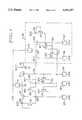
- FIG. 1is a detailed schematic diagram of a circuit embodying the present invention
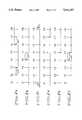
- FIGS. 2(a)-(f)are timing diagrams for the FIG. 1 embodiment.
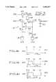
- FIG. 3is a schematic diagram of a prior art charge pump using n-channel transistors
- FIGS. 4(a)-(c)are timing diagrams for the FIG. 3 circuit
- FIG. 5is a schematic diagram of a prior art dual-stage charge pump
- FIGS. 6(a)-(d)are timing diagrams for the dual-stage pump of FIG. 5;
- FIG. 7is a graph of the efficiencies of the single- and dual-stage pumps, and the pump of the present invention.
- FIG. 1is a schematic diagram of the preferred circuit embodiment of the present invention. Preferably, this circuit is fabricated on an integrated circuit. All of the elements of FIG. 1 are n-channel enhancement mode devices, unless otherwise indicated.
- the preferred embodimentincludes a secondary pump consisting of the elements shown in block 10 of FIG. 1.
- a main pumpincludes the elements shown outside of block 10.
- the FIG. 1 circuitis coupled to receive six clock input signals CP1 to CP6. It will be understood that clock pulses CP1, CP2 and CP3, and times T1-T7 are not necessarily the same as in the other figures. Each such clock input is applied to a corresponding capacitor, except that clock pulse CP1 is supplied to electrodes of capacitors 11 and 12. A first node 13 is coupled to another electrode of capacitor 11.
- Node 13is selectively coupled to a first power supply, typically 5 volts, through a source-drain path of a transistor 14.
- the first power supply voltageis referred to as VCC, which may also be called a source of operating voltage.
- Node 13is also selectively coupled through a source-drain path of a transistor 15 to an output node 16.
- Node 16has a capacitive load CLoad designated by 17.
- a second node 24is coupled to a gate of transistor 14. Node 24 is selectively coupled to VCC through source-drain paths of any of transistors 19, 20 and 21. Node 24 is also coupled to an electrode of a capacitor 22. A gate electrode of transistor 19 is coupled to the first power supply. A clock pulse CP2 is coupled to another electrode of capacitor 22.
- a third node 26is coupled to gate electrodes of transistors 15, 20 and 30. Node 26 is selectively coupled to VCC through a source-drain path of a transistor 28. Further, node 26 is selectively coupled to a node 58 through a source-drain path of a transistor 32. Node 26 is also coupled to an electrode of capacitor 34. A clock pulse CP3 is coupled to another electrode of capacitor 34.
- a fourth node 36is coupled to a gate electrode of transistor 28. Node 36 is selectively coupled to VCC through a source-drain path of transistor 30. Node 36 is also coupled to an electrode of capacitor 38. A clock pulse CP5 is coupled to another electrode of capacitor 38. Fourth node 36 also is coupled to the gate electrode of transistor 28.
- a fifth node 48is coupled to gate electrodes of transistors 42 and 50.
- Node 48is selectively coupled to VCC through source-drain paths of transistors 44 and 52.
- a gate electrode of transistor 52is coupled to the first power supply.
- Node 48is also coupled to an electrode of capacitor 54.
- a clock pulse CP6is coupled to another electrode of capacitor 54.
- a source-drain path of transistor 50selectively couples node 58 to VCC.
- An electrode of capacitor 12is coupled to node 58.
- a node 40is coupled to gate electrodes of transistors 21, 32 and 44. Node 40 is selectively coupled to VCC through a source-drain path of transistor 42. Node 40 is also coupled to an electrode of capacitor 46. A clock pulse CP4 is coupled to another electrode of capacitor 46.
- Capacitors 11, 12, 22, 34, 38, 46 and 54are preferably n-channel transistors having their respective source and drain electrodes shorted together to form one electrode of the capacitor.
- the gate electrodeis the other electrode of the capacitor.
- nodes 13, 24, 26, 36, 40, 48 and 58follow clock pulses CP1, CP2, CP3, CP5, CP4, CP6 and CP1, respectively.
- Nodes 13, 24, 36, 40, 48 and 58should operate between, for example, VCC and 2 VCC.
- Node 26should operate between, for example, VCC and 3 VCC-Vt N .
- clock pulse CP3transitions from an active state (high) to an inactive state (low) which turns off transistor 15 and decouples CLoad (node 16) from node 13.
- clock pulse CP5transitions from an inactive state (low) to an active state (high). The timing of clock pulses CP3 and CP5 insures that node 26 will not discharge positive charge through transistor 28 while clock pulses CP3 and CP5 are active. With clock pulse CP5 active, transistor 28 turns on to couple node 26 to VCC. Capacitor 34 is charged through node 26 from the power supply providing voltage VCC.
- a preferred time delay 60 between T2 and T3is imposed to insure that node 26 equals VCC before clock pulse CP1 transitions to an inactive state (low) at a time a T3. This preferred delay is used to prevent transistor 15 from turning on when clock pulse CP1 transitions to an inactive state (low), which would cause pumped charge from leaking out of capacitive load 17 to node 13.
- clock pulse CP1transitions to an inactive state (low), and nodes 13 and 58 transition from a positive voltage to a positive voltage slightly below VCC(VCC- ⁇ V).
- clock pulse CP2goes to the active state (high). This causes nodes 13 and 58 to charge to VCC via transistors 14 and 50, respectively.
- a preferred time delay 62is needed to insure the discharge of capacitors 11 and 12 to VCC.
- clock pulses CP2, CP4, CP5 and CP6change states.
- Clock pulses CP2 and CP6become inactive (low) before clock pulse CP1 becomes active to prevent the further discharge of capacitors 11 and 12 to VCC by turning off transistors 14 and 50.
- Clock pulse CP5becomes inactive (low) to unclamp node 26 from VCC by turning off transistor 28.
- Clock pulse CP4becomes active (high) to allow a positive charging of node 26 by turning on transistor 32 before clock pulse CP1 transitions to an active state (high).
- clock pulse CP5it is not necessary for clock pulse CP5 to transition inactive (low) before clock pulse CP4 transitions to an active state (high) since node 26 and node 56 are both at the voltage potential VCC, and no charge transfer will occur until clock pulse CP1 transitions to an active state (high).
- clock pulse CP1transitions to an active state (high). Positive charge is pumped into node 26 via transistor 32 from node 58.
- the voltage at node 26is determined by the following equation: ##EQU2## where Vnode26 is the maximum theoretical pumped voltage at node 26, and C12 and C34 are the capacitive values 12 and 34, respectively.
- Vnode26can approach values of 2 VCC if the capacitance of capacitor 12 is much greater than the capacitance of capacitor 34.
- the maximum voltage that node 26 can approachis 2 VCC-Vt N .
- the voltage on node 26would approach 3 VCC/2.
- clock pulse CP4transitions to an inactive state (low) to turn transistor 32 off and decouple node 26 from node 58. This is done in preparation of clock pulse CP3 transitioning at time T8. With node 26 decoupled from node 58, the voltage on node 26 is mainly a function of the capacitance of capacitor 34 and the gate capacitance of transistor 15.
- clock pulse CP3transitions to an active state (high).
- the voltage on node 26rises by another voltage VCC (since the capacitance of capacitor 34 is much greater than the gate capacitance of transistor 15).
- the voltage on node 26is 3 VCC-Vt N or 2.5 VCC, depending on whether node 26 was initially charged to 2 VCC-Vt N or 3 VCC/2 at a time T6 (again note that this was dependent on the sizes of capacitors 34 and 12).
- a preferred time delay 63is used to insure the transfer or pumping of all positive charge from capacitor 11 to CLoad.
- the voltage of the drain of transistor 15is equal to 2 VCC and the voltage of the gate of transistor 15 (also node 26) equal to 3 VCC-Vt N or 2.5 VCC.
- Transistor 15will stay on while node 13 (capacitor 11) charges CLoad to a full theoretical 2 VCC because the gate voltage of transistor 15 is a threshold voltage Vt N greater than 2 VCC.
- clock pulse CP1transitions only when clock pulses CP2 and CP6 are inactive (low). This avoids the discharge of charged nodes 13 and 58 to power supply VCC while transistors 14 and 50 are respectively on, and the charged capacitive load coupled to pumped node 16 from discharging to power supply VCC.
- Clock pulses CP2 and CP3 as well as CP3 and CP6are preferably non-overlapping when active.
- a main charge pumpcomprises transistors 14 and 15, nodes 13, 18, 24 and 26, capacitors 11, 22 and 34, and pumped node 16.
- a secondary charge pumpconsists of transistors 32 and 50, a connection to main control node 26, nodes 40, 48, 56, and 58, and capacitors 12, 46 and 54.
- the efficiency of the circuitis calculated as: ##EQU3## where I Vccp is the current of the capacitive load charged to VCCP, I Vcc1 is the power supply VCC current of the charge pump and I Vcc2 is the power supply VCC current of the secondary charge pump.
- Line 140represents the efficiency of the single-stage pump.
- Line 142represents the efficiency of the dual-stage pump.
- Line 144represents the efficiency of the preferred embodiment of the present invention.
- FIG. 1 embodimentprovides a full 2 VCC. This would allow the preferred embodiment to be used unregulated in some applications requiring a full 2 VCC.
- any variation in voltage supply VCC, down to 2 V,will still enable main control node 26 to achieve a voltage that is a threshold voltage Vt N greater than 2 VCC. It follows that the preferred embodiment of the present invention can have a supply voltage VCC as low as 2 V. Further, since the device can operate at voltages as low as 2 V, it will also operate with greater voltages and therefore tolerate a wider voltage range for the power supply VCC.
- the secondary charge pumpcan be replaced by other devices (circuits) which charge node 26 to a voltage Vt N greater than VCCP without departing from the spirit of the present invention.
- capacitors 11, 12, 22, 34, 38, 46 and 54are transistors with their source and drain electrodes connected together.
- Clock pulses CP1-CP6are preferably coupled to the source and drain electrodes connected together.
- the gate electrodes of these transistorsare coupled to their respective nodes in the preferred embodiment.
- the present inventionis not limited to using transistors as capacitors and may be replaced by other elements that have a capacitive function. Also, other types of transistors can be used, including bipolar ones.
- transistors 14 and 15be larger (greater channel width to length ratio) than transistors 32 and 50. Such an arrangement is allowed because transistors 32 and 50 are pumping only main control node 26, and therefore require less current passing capabilities compared to transistors 14 and 15.
- Transistors 16 and 52can be equivalent in size to each other. Transistors 20, 21, 28 and 30 may be larger than transistors 42 and 44. Transistor 28 may be larger than transistors 20, 21 and 30 to quickly discharge node 26 to VCC. Otherwise, transistor 28 should be turned on for a sufficient time to fully discharge node 26 to VCC. Also, capacitor 12 can be smaller than capacitor 11 since capacitor 12 is providing charge only to node 26.
Landscapes
- Engineering & Computer Science (AREA)
- Power Engineering (AREA)
- Dc-Dc Converters (AREA)
- Logic Circuits (AREA)
- Dram (AREA)
- Read Only Memory (AREA)
Abstract
Description
Claims (29)
Priority Applications (4)
| Application Number | Priority Date | Filing Date | Title |
|---|---|---|---|
| US07/964,003US5412257A (en) | 1992-10-20 | 1992-10-20 | High efficiency N-channel charge pump having a primary pump and a non-cascaded secondary pump |
| EP93202505AEP0594230B1 (en) | 1992-10-20 | 1993-08-26 | High efficiency n-channel charge pump |
| DE69310310TDE69310310T2 (en) | 1992-10-20 | 1993-08-26 | High performance N-channel charge pump |
| JP24925493AJP2815293B2 (en) | 1992-10-20 | 1993-10-05 | High efficiency n-channel charge pump |
Applications Claiming Priority (1)
| Application Number | Priority Date | Filing Date | Title |
|---|---|---|---|
| US07/964,003US5412257A (en) | 1992-10-20 | 1992-10-20 | High efficiency N-channel charge pump having a primary pump and a non-cascaded secondary pump |
Publications (1)
| Publication Number | Publication Date |
|---|---|
| US5412257Atrue US5412257A (en) | 1995-05-02 |
Family
ID=25508012
Family Applications (1)
| Application Number | Title | Priority Date | Filing Date |
|---|---|---|---|
| US07/964,003Expired - LifetimeUS5412257A (en) | 1992-10-20 | 1992-10-20 | High efficiency N-channel charge pump having a primary pump and a non-cascaded secondary pump |
Country Status (4)
| Country | Link |
|---|---|
| US (1) | US5412257A (en) |
| EP (1) | EP0594230B1 (en) |
| JP (1) | JP2815293B2 (en) |
| DE (1) | DE69310310T2 (en) |
Cited By (17)
| Publication number | Priority date | Publication date | Assignee | Title |
|---|---|---|---|---|
| US5483434A (en)* | 1992-01-14 | 1996-01-09 | Seesink; Petrus H. | High voltage generator having output current control |
| US5650671A (en)* | 1994-01-28 | 1997-07-22 | Sgs-Thomson Microelectronics S.R.L. | Charge pump circuit |
| US5677645A (en)* | 1995-05-08 | 1997-10-14 | Micron Technology, Inc. | Vccp pump for low voltage operation |
| US5764097A (en)* | 1994-11-15 | 1998-06-09 | Sgs-Thomson Microelectronics Limited | Automatically biased voltage level converter |
| US5831470A (en)* | 1995-11-23 | 1998-11-03 | Lg Semicon Co., Ltd | High-efficiency charge pumping circuit |
| US5838190A (en)* | 1995-10-14 | 1998-11-17 | Hyundai Electronics Industries, Co., Ltd. | Negative voltage drive circuit |
| US6016073A (en)* | 1996-11-14 | 2000-01-18 | Sgs-Thomson Microelectronics S.R.L. | BiCMOS negative charge pump |
| US6198339B1 (en) | 1996-09-17 | 2001-03-06 | International Business Machines Corporation | CVF current reference with standby mode |
| US6208197B1 (en) | 1999-03-04 | 2001-03-27 | Vanguard International Semiconductor Corp. | Internal charge pump voltage limit control |
| US6255896B1 (en)* | 1999-09-27 | 2001-07-03 | Intel Corporation | Method and apparatus for rapid initialization of charge pump circuits |
| US6337595B1 (en)* | 2000-07-28 | 2002-01-08 | International Business Machines Corporation | Low-power DC voltage generator system |
| US6504421B2 (en) | 1993-10-15 | 2003-01-07 | Micron Technology, Inc. | Voltage pump and a level translator circuit |
| US20050068811A1 (en)* | 2003-09-29 | 2005-03-31 | Cordoba Michael V. | Non-cascading charge pump circuit and method |
| US7034652B2 (en)* | 2001-07-10 | 2006-04-25 | Littlefuse, Inc. | Electrostatic discharge multifunction resistor |
| US20060109047A1 (en)* | 2004-11-22 | 2006-05-25 | Stmicroelectronics S.R.L. | Charge pump circuit with dynamic biasing of pass transistors |
| US20060255853A1 (en)* | 2005-04-28 | 2006-11-16 | Hiroyuki Masuko | Electronic device including charge pump circuit |
| WO2009014747A1 (en)* | 2007-07-26 | 2009-01-29 | International Rectifier Corporation | Double stage compact charge pump circuit |
Families Citing this family (2)
| Publication number | Priority date | Publication date | Assignee | Title |
|---|---|---|---|---|
| GB2324423B (en)* | 1997-04-16 | 1999-07-21 | Lsi Logic Corp | Charge pump |
| KR100757410B1 (en) | 2005-09-16 | 2007-09-11 | 삼성전자주식회사 | Phase change memory device and its programming method |
Citations (38)
| Publication number | Priority date | Publication date | Assignee | Title |
|---|---|---|---|---|
| US3872321A (en)* | 1972-09-25 | 1975-03-18 | Nippon Electric Co | Inverter circuit employing field effect transistors |
| US4061929A (en)* | 1975-09-22 | 1977-12-06 | Kabushiki Kaisha Daini Seikosha | Circuit for obtaining DC voltage higher than power source voltage |
| EP0030856A1 (en)* | 1979-12-13 | 1981-06-24 | Fujitsu Limited | Charge-pumping semiconductor memory cell comprising a charge-storage region and memory device using such a cell |
| US4336466A (en)* | 1980-06-30 | 1982-06-22 | Inmos Corporation | Substrate bias generator |
| US4382194A (en)* | 1979-12-05 | 1983-05-03 | Fujitsu Limited | Boosting circuit |
| US4388537A (en)* | 1979-12-27 | 1983-06-14 | Tokyo Shibaura Denki Kabushiki Kaisha | Substrate bias generation circuit |
| EP0143157A1 (en)* | 1983-10-27 | 1985-06-05 | International Business Machines Corporation | Charge pumping circuit for a substrate voltage generator |
| US4578597A (en)* | 1982-03-05 | 1986-03-25 | Sony Corporation | Large amplitude pulse generating circuits |
| US4578601A (en)* | 1983-12-07 | 1986-03-25 | Motorola, Inc. | High speed TTL clock input buffer circuit which minimizes power and provides CMOS level translation |
| US4581546A (en)* | 1983-11-02 | 1986-04-08 | Inmos Corporation | CMOS substrate bias generator having only P channel transistors in the charge pump |
| US4631421A (en)* | 1984-08-14 | 1986-12-23 | Texas Instruments | CMOS substrate bias generator |
| US4633106A (en)* | 1983-05-27 | 1986-12-30 | Itt Industries, Inc. | MOS bootstrap push-pull stage |
| US4638464A (en)* | 1983-11-14 | 1987-01-20 | International Business Machines Corp. | Charge pump system for non-volatile ram |
| US4705966A (en)* | 1984-09-11 | 1987-11-10 | U.S. Philips Corporation | Circuit for generating a substrate bias |
| US4731552A (en)* | 1985-05-14 | 1988-03-15 | Mitsubishi Denki Kabushiki Kaisha | Boost signal generator with bootstrap means |
| US4733108A (en)* | 1982-06-28 | 1988-03-22 | Xerox Corporation | On-chip bias generator |
| US4797899A (en)* | 1986-12-15 | 1989-01-10 | Maxim Integrated Products, Inc. | Integrated dual charge pump power supply including power down feature and rs-232 transmitter/receiver |
| US4843256A (en)* | 1986-12-23 | 1989-06-27 | Jenoptik Jena Gmbh | Controlled CMOS substrate voltage generator |
| US4883976A (en)* | 1987-12-02 | 1989-11-28 | Xicor, Inc. | Low power dual-mode CMOS bias voltage generator |
| US4922130A (en)* | 1988-05-26 | 1990-05-01 | Hewlett-Packard Company | High performance track/hold for a digital multimeter |
| EP0379454A1 (en)* | 1989-01-23 | 1990-07-25 | STMicroelectronics S.A. | MOS power transistor circuit controlled by a device with two symmetrical charging pumps |
| EP0389846A2 (en)* | 1989-03-25 | 1990-10-03 | EUROSIL electronic GmbH | Voltage multiplier circuit |
| EP0404124A2 (en)* | 1989-06-20 | 1990-12-27 | Nec Corporation | Charge pump having pull-up circuit operating with two clock pulse sequences |
| US4984256A (en)* | 1987-02-13 | 1991-01-08 | Kabushiki Kaisha Toshiba | Charge transfer device with booster circuit |
| EP0427084A2 (en)* | 1989-11-08 | 1991-05-15 | National Semiconductor Corporation | Maximum swing cascode circuit for a bipolar charge pump |
| US5036229A (en)* | 1989-07-18 | 1991-07-30 | Gazelle Microcircuits, Inc. | Low ripple bias voltage generator |
| US5041739A (en)* | 1989-08-14 | 1991-08-20 | Nec Corporation | Substrate potential generating circuit |
| EP0450797A1 (en)* | 1990-04-05 | 1991-10-09 | Advanced Micro Devices, Inc. | Charge pump apparatus |
| EP0450796A2 (en)* | 1990-04-05 | 1991-10-09 | Advanced Micro Devices, Inc. | Capacitor charge pumps |
| US5103191A (en)* | 1989-07-25 | 1992-04-07 | Siemens Aktiengesellschaft | Circuit configuration for phase locking |
| US5113088A (en)* | 1988-11-09 | 1992-05-12 | Oki Electric Industry Co., Ltd. | Substrate bias generating circuitry stable against source voltage changes |
| US5126590A (en)* | 1991-06-17 | 1992-06-30 | Micron Technology, Inc. | High efficiency charge pump |
| US5162668A (en)* | 1990-12-14 | 1992-11-10 | International Business Machines Corporation | Small dropout on-chip voltage regulators with boosted power supply |
| US5172013A (en)* | 1990-06-25 | 1992-12-15 | Sony Corporation | Substrate bias generator for semiconductor devices |
| US5180928A (en)* | 1991-09-30 | 1993-01-19 | Samsung Electronics Co., Ltd. | Constant voltage generation of semiconductor device |
| US5184030A (en)* | 1991-04-12 | 1993-02-02 | Goldstar Electron Co., Ltd. | Back bias generating circuit |
| US5196996A (en)* | 1990-08-17 | 1993-03-23 | Hyundai Electronics Industries Co., Ltd. | High voltage generating circuit for semiconductor devices having a charge pump for eliminating diode threshold voltage losses |
| US5266842A (en)* | 1991-10-25 | 1993-11-30 | Samsung Electronics Co., Ltd. | Charge pump circuit for a substrate voltage generator |
- 1992
- 1992-10-20USUS07/964,003patent/US5412257A/ennot_activeExpired - Lifetime
- 1993
- 1993-08-26EPEP93202505Apatent/EP0594230B1/ennot_activeExpired - Lifetime
- 1993-08-26DEDE69310310Tpatent/DE69310310T2/ennot_activeExpired - Lifetime
- 1993-10-05JPJP24925493Apatent/JP2815293B2/ennot_activeExpired - Fee Related
Patent Citations (40)
| Publication number | Priority date | Publication date | Assignee | Title |
|---|---|---|---|---|
| US3872321A (en)* | 1972-09-25 | 1975-03-18 | Nippon Electric Co | Inverter circuit employing field effect transistors |
| US4061929A (en)* | 1975-09-22 | 1977-12-06 | Kabushiki Kaisha Daini Seikosha | Circuit for obtaining DC voltage higher than power source voltage |
| US4382194A (en)* | 1979-12-05 | 1983-05-03 | Fujitsu Limited | Boosting circuit |
| EP0030856A1 (en)* | 1979-12-13 | 1981-06-24 | Fujitsu Limited | Charge-pumping semiconductor memory cell comprising a charge-storage region and memory device using such a cell |
| US4388537A (en)* | 1979-12-27 | 1983-06-14 | Tokyo Shibaura Denki Kabushiki Kaisha | Substrate bias generation circuit |
| US4336466A (en)* | 1980-06-30 | 1982-06-22 | Inmos Corporation | Substrate bias generator |
| US4578597A (en)* | 1982-03-05 | 1986-03-25 | Sony Corporation | Large amplitude pulse generating circuits |
| US4733108A (en)* | 1982-06-28 | 1988-03-22 | Xerox Corporation | On-chip bias generator |
| US4633106A (en)* | 1983-05-27 | 1986-12-30 | Itt Industries, Inc. | MOS bootstrap push-pull stage |
| EP0143157A1 (en)* | 1983-10-27 | 1985-06-05 | International Business Machines Corporation | Charge pumping circuit for a substrate voltage generator |
| US4581546A (en)* | 1983-11-02 | 1986-04-08 | Inmos Corporation | CMOS substrate bias generator having only P channel transistors in the charge pump |
| US4638464A (en)* | 1983-11-14 | 1987-01-20 | International Business Machines Corp. | Charge pump system for non-volatile ram |
| US4578601A (en)* | 1983-12-07 | 1986-03-25 | Motorola, Inc. | High speed TTL clock input buffer circuit which minimizes power and provides CMOS level translation |
| US4631421A (en)* | 1984-08-14 | 1986-12-23 | Texas Instruments | CMOS substrate bias generator |
| US4705966A (en)* | 1984-09-11 | 1987-11-10 | U.S. Philips Corporation | Circuit for generating a substrate bias |
| US4731552A (en)* | 1985-05-14 | 1988-03-15 | Mitsubishi Denki Kabushiki Kaisha | Boost signal generator with bootstrap means |
| US4797899A (en)* | 1986-12-15 | 1989-01-10 | Maxim Integrated Products, Inc. | Integrated dual charge pump power supply including power down feature and rs-232 transmitter/receiver |
| US4843256A (en)* | 1986-12-23 | 1989-06-27 | Jenoptik Jena Gmbh | Controlled CMOS substrate voltage generator |
| US4984256A (en)* | 1987-02-13 | 1991-01-08 | Kabushiki Kaisha Toshiba | Charge transfer device with booster circuit |
| US4883976A (en)* | 1987-12-02 | 1989-11-28 | Xicor, Inc. | Low power dual-mode CMOS bias voltage generator |
| US4922130A (en)* | 1988-05-26 | 1990-05-01 | Hewlett-Packard Company | High performance track/hold for a digital multimeter |
| US5113088A (en)* | 1988-11-09 | 1992-05-12 | Oki Electric Industry Co., Ltd. | Substrate bias generating circuitry stable against source voltage changes |
| EP0379454A1 (en)* | 1989-01-23 | 1990-07-25 | STMicroelectronics S.A. | MOS power transistor circuit controlled by a device with two symmetrical charging pumps |
| EP0389846A2 (en)* | 1989-03-25 | 1990-10-03 | EUROSIL electronic GmbH | Voltage multiplier circuit |
| US5066870A (en)* | 1989-06-20 | 1991-11-19 | Nec Corporation | Charge pump having pull-up circuit operating with two clock pulse sequences |
| EP0404124A2 (en)* | 1989-06-20 | 1990-12-27 | Nec Corporation | Charge pump having pull-up circuit operating with two clock pulse sequences |
| US5036229A (en)* | 1989-07-18 | 1991-07-30 | Gazelle Microcircuits, Inc. | Low ripple bias voltage generator |
| US5103191A (en)* | 1989-07-25 | 1992-04-07 | Siemens Aktiengesellschaft | Circuit configuration for phase locking |
| US5041739A (en)* | 1989-08-14 | 1991-08-20 | Nec Corporation | Substrate potential generating circuit |
| EP0427084A2 (en)* | 1989-11-08 | 1991-05-15 | National Semiconductor Corporation | Maximum swing cascode circuit for a bipolar charge pump |
| EP0450797A1 (en)* | 1990-04-05 | 1991-10-09 | Advanced Micro Devices, Inc. | Charge pump apparatus |
| US5059815A (en)* | 1990-04-05 | 1991-10-22 | Advanced Micro Devices, Inc. | High voltage charge pumps with series capacitors |
| EP0450796A2 (en)* | 1990-04-05 | 1991-10-09 | Advanced Micro Devices, Inc. | Capacitor charge pumps |
| US5172013A (en)* | 1990-06-25 | 1992-12-15 | Sony Corporation | Substrate bias generator for semiconductor devices |
| US5196996A (en)* | 1990-08-17 | 1993-03-23 | Hyundai Electronics Industries Co., Ltd. | High voltage generating circuit for semiconductor devices having a charge pump for eliminating diode threshold voltage losses |
| US5162668A (en)* | 1990-12-14 | 1992-11-10 | International Business Machines Corporation | Small dropout on-chip voltage regulators with boosted power supply |
| US5184030A (en)* | 1991-04-12 | 1993-02-02 | Goldstar Electron Co., Ltd. | Back bias generating circuit |
| US5126590A (en)* | 1991-06-17 | 1992-06-30 | Micron Technology, Inc. | High efficiency charge pump |
| US5180928A (en)* | 1991-09-30 | 1993-01-19 | Samsung Electronics Co., Ltd. | Constant voltage generation of semiconductor device |
| US5266842A (en)* | 1991-10-25 | 1993-11-30 | Samsung Electronics Co., Ltd. | Charge pump circuit for a substrate voltage generator |
Non-Patent Citations (8)
| Title |
|---|
| Gillingham et al., "High-Speed, High-Reliability Circuit Design for Megabit DRAM," IEEE Journal of Solid-State Circuits, vol. 26, No. 8, pp. 1171-1175 (Aug. 1991). |
| Gillingham et al., High Speed, High Reliability Circuit Design for Megabit DRAM, IEEE Journal of Solid State Circuits, vol. 26, No. 8, pp. 1171 1175 (Aug. 1991).* |
| Glasser et al., "Substrate-bias generation," Design and Analysis of VLSI Circuits, chap. 5.8, pp. 301-308 (Addison-Wesley 1985). |
| Glasser et al., Substrate bias generation, Design and Analysis of VLSI Circuits, chap. 5.8, pp. 301 308 (Addison Wesley 1985).* |
| Martino et al., "An On-Chip Back-Bias Generator for MOS Dynamic Memory," IEEE Journal of Solid-State Circuits, vol. SC-15, No. 5, pp. 820-825 (Oct. 1990). |
| Martino et al., An On Chip Back Bias Generator for MOS Dynamic Memory, IEEE Journal of Solid State Circuits, vol. SC 15, No. 5, pp. 820 825 (Oct. 1990).* |
| Oto et al., "High-Voltage Regulation and Process Considerations for High-Density 5 V-only E2 PROMS's," IEEE Journal of Solid-State Circuits, vol. SC-18, No. 5, pp. 532-538 (Oct. 1983). |
| Oto et al., High Voltage Regulation and Process Considerations for High Density 5 V only E 2 PROMS s, IEEE Journal of Solid State Circuits, vol. SC 18, No. 5, pp. 532 538 (Oct. 1983).* |
Cited By (23)
| Publication number | Priority date | Publication date | Assignee | Title |
|---|---|---|---|---|
| US5483434A (en)* | 1992-01-14 | 1996-01-09 | Seesink; Petrus H. | High voltage generator having output current control |
| US6750695B2 (en) | 1993-10-15 | 2004-06-15 | Micron Technology, Inc. | Voltage pump and a level translator circuit |
| US6504421B2 (en) | 1993-10-15 | 2003-01-07 | Micron Technology, Inc. | Voltage pump and a level translator circuit |
| US5650671A (en)* | 1994-01-28 | 1997-07-22 | Sgs-Thomson Microelectronics S.R.L. | Charge pump circuit |
| US5764097A (en)* | 1994-11-15 | 1998-06-09 | Sgs-Thomson Microelectronics Limited | Automatically biased voltage level converter |
| US5677645A (en)* | 1995-05-08 | 1997-10-14 | Micron Technology, Inc. | Vccp pump for low voltage operation |
| US5838190A (en)* | 1995-10-14 | 1998-11-17 | Hyundai Electronics Industries, Co., Ltd. | Negative voltage drive circuit |
| DE19642377B4 (en)* | 1995-10-14 | 2014-10-30 | Hyundai Electronics Industries Co., Ltd. | Negative voltage driver circuit |
| US5831470A (en)* | 1995-11-23 | 1998-11-03 | Lg Semicon Co., Ltd | High-efficiency charge pumping circuit |
| US6198339B1 (en) | 1996-09-17 | 2001-03-06 | International Business Machines Corporation | CVF current reference with standby mode |
| US6016073A (en)* | 1996-11-14 | 2000-01-18 | Sgs-Thomson Microelectronics S.R.L. | BiCMOS negative charge pump |
| US6208197B1 (en) | 1999-03-04 | 2001-03-27 | Vanguard International Semiconductor Corp. | Internal charge pump voltage limit control |
| US6255896B1 (en)* | 1999-09-27 | 2001-07-03 | Intel Corporation | Method and apparatus for rapid initialization of charge pump circuits |
| US6337595B1 (en)* | 2000-07-28 | 2002-01-08 | International Business Machines Corporation | Low-power DC voltage generator system |
| US6507237B2 (en)* | 2000-07-28 | 2003-01-14 | Ibm Corporation | Low-power DC voltage generator system |
| US7034652B2 (en)* | 2001-07-10 | 2006-04-25 | Littlefuse, Inc. | Electrostatic discharge multifunction resistor |
| US20050068811A1 (en)* | 2003-09-29 | 2005-03-31 | Cordoba Michael V. | Non-cascading charge pump circuit and method |
| US6952116B2 (en)* | 2003-09-29 | 2005-10-04 | Micron Technology, Inc. | Non-cascading charge pump circuit and method |
| US20060109047A1 (en)* | 2004-11-22 | 2006-05-25 | Stmicroelectronics S.R.L. | Charge pump circuit with dynamic biasing of pass transistors |
| US7248096B2 (en) | 2004-11-22 | 2007-07-24 | Stmicroelectronics S.R.L. | Charge pump circuit with dynamic biasing of pass transistors |
| US20060255853A1 (en)* | 2005-04-28 | 2006-11-16 | Hiroyuki Masuko | Electronic device including charge pump circuit |
| US7436239B2 (en)* | 2005-04-28 | 2008-10-14 | Seiko Instruments Inc. | Electronic device including charge pump circuit |
| WO2009014747A1 (en)* | 2007-07-26 | 2009-01-29 | International Rectifier Corporation | Double stage compact charge pump circuit |
Also Published As
| Publication number | Publication date |
|---|---|
| JPH06217527A (en) | 1994-08-05 |
| EP0594230B1 (en) | 1997-05-02 |
| EP0594230A1 (en) | 1994-04-27 |
| DE69310310T2 (en) | 1997-08-14 |
| JP2815293B2 (en) | 1998-10-27 |
| DE69310310D1 (en) | 1997-06-05 |
Similar Documents
| Publication | Publication Date | Title |
|---|---|---|
| US5347171A (en) | Efficient negative charge pump | |
| US5412257A (en) | High efficiency N-channel charge pump having a primary pump and a non-cascaded secondary pump | |
| US6359501B2 (en) | Charge-pumping circuits for a low-supply voltage | |
| US6501325B1 (en) | Low voltage supply higher efficiency cross-coupled high voltage charge pumps | |
| US6130572A (en) | NMOS negative charge pump | |
| US4621315A (en) | Recirculating MOS charge pump | |
| US6154088A (en) | Clocking scheme and charge transfer switch for increasing the efficiency of a charge pump or other circuit | |
| US7046076B2 (en) | High efficiency, low cost, charge pump circuit | |
| US6184741B1 (en) | Bidirectional charge pump generating either a positive or negative voltage | |
| US20080143401A1 (en) | Charge pump circuit | |
| US5493486A (en) | High efficiency compact low power voltage doubler circuit | |
| US6356137B1 (en) | Voltage boost circuit with low power supply voltage | |
| CN111969844B (en) | Bootstrap charge pump high-voltage power supply generation circuit | |
| KR101295777B1 (en) | Charge pumping circuit | |
| US5760497A (en) | Charge pump circuit with multiple boost stages | |
| US6605985B2 (en) | High-efficiency power charge pump supplying high DC output currents | |
| US20240372543A1 (en) | MULTIPHASE N-CHANNEL HIGH-SIDE SWITCH FOR GaN INTEGRATED CIRCUITS | |
| CN114157141B (en) | Charge pump and integrated circuit chip | |
| US12040705B2 (en) | Self clocked low power doubling charge pump | |
| US6177829B1 (en) | Device for improving the switching efficiency of an integrated circuit charge pump | |
| KR100576812B1 (en) | Charge pump circuit and high voltage generation circuit | |
| JPH0430207B2 (en) | ||
| US6631081B2 (en) | Capacitive high voltage generator | |
| US7148739B2 (en) | Charge pump element with body effect cancellation for early charge pump stages | |
| KR940006072Y1 (en) | Back bias voltage generation circuit |
Legal Events
| Date | Code | Title | Description |
|---|---|---|---|
| AS | Assignment | Owner name:UNITED MEMORIES, INC., COLORADO Free format text:ASSIGNMENT OF ASSIGNORS INTEREST.;ASSIGNORS:CORDOBA, MICHAEL V.;HARDEE, KIM C.;REEL/FRAME:006286/0194 Effective date:19921009 | |
| AS | Assignment | Owner name:NIPPON STEEL SEMICONDUCTOR CORPORATION, JAPAN Free format text:CHANGE OF NAME;ASSIGNOR:NMB SEMICONDUCTOR COMPANY, LTD.;REEL/FRAME:006554/0575 Effective date:19930323 | |
| STCF | Information on status: patent grant | Free format text:PATENTED CASE | |
| FEPP | Fee payment procedure | Free format text:PAYOR NUMBER ASSIGNED (ORIGINAL EVENT CODE: ASPN); ENTITY STATUS OF PATENT OWNER: LARGE ENTITY | |
| FPAY | Fee payment | Year of fee payment:4 | |
| AS | Assignment | Owner name:MOSEL VITELIC INC., TAIWAN Free format text:ASSIGNMENT OF ASSIGNORS INTEREST;ASSIGNORS:UNITED MEMORIES INC.;NIPPON FOUNDRY INC.;REEL/FRAME:010272/0141 Effective date:19990302 Owner name:NIPPON FOUNDRY INC., JAPAN Free format text:CHANGE OF NAME;ASSIGNOR:N.M.B. SEMICONDUCTOR, INC.;REEL/FRAME:010272/0072 Effective date:19990108 | |
| FEPP | Fee payment procedure | Free format text:PAYER NUMBER DE-ASSIGNED (ORIGINAL EVENT CODE: RMPN); ENTITY STATUS OF PATENT OWNER: LARGE ENTITY Free format text:PAYOR NUMBER ASSIGNED (ORIGINAL EVENT CODE: ASPN); ENTITY STATUS OF PATENT OWNER: LARGE ENTITY | |
| FPAY | Fee payment | Year of fee payment:8 | |
| AS | Assignment | Owner name:PROMOS TECHNOLOGIES INC., TAIWAN Free format text:ASSIGNMENT OF ASSIGNORS INTEREST;ASSIGNOR:MOSEL VITELIC, INC.;REEL/FRAME:015334/0772 Effective date:20040427 | |
| FPAY | Fee payment | Year of fee payment:12 |