US5411602A - Solder compositions and methods of making same - Google Patents
Solder compositions and methods of making sameDownload PDFInfo
- Publication number
- US5411602A US5411602AUS08/197,750US19775094AUS5411602AUS 5411602 AUS5411602 AUS 5411602AUS 19775094 AUS19775094 AUS 19775094AUS 5411602 AUS5411602 AUS 5411602A
- Authority
- US
- United States
- Prior art keywords
- solder
- set forth
- liquid
- ejection device
- balls
- Prior art date
- Legal status (The legal status is an assumption and is not a legal conclusion. Google has not performed a legal analysis and makes no representation as to the accuracy of the status listed.)
- Expired - Lifetime
Links
Images


Classifications
- B—PERFORMING OPERATIONS; TRANSPORTING
- B22—CASTING; POWDER METALLURGY
- B22F—WORKING METALLIC POWDER; MANUFACTURE OF ARTICLES FROM METALLIC POWDER; MAKING METALLIC POWDER; APPARATUS OR DEVICES SPECIALLY ADAPTED FOR METALLIC POWDER
- B22F9/00—Making metallic powder or suspensions thereof
- B22F9/02—Making metallic powder or suspensions thereof using physical processes
- B22F9/06—Making metallic powder or suspensions thereof using physical processes starting from liquid material
- B22F9/08—Making metallic powder or suspensions thereof using physical processes starting from liquid material by casting, e.g. through sieves or in water, by atomising or spraying
- B—PERFORMING OPERATIONS; TRANSPORTING
- B22—CASTING; POWDER METALLURGY
- B22F—WORKING METALLIC POWDER; MANUFACTURE OF ARTICLES FROM METALLIC POWDER; MAKING METALLIC POWDER; APPARATUS OR DEVICES SPECIALLY ADAPTED FOR METALLIC POWDER
- B22F1/00—Metallic powder; Treatment of metallic powder, e.g. to facilitate working or to improve properties
- B22F1/06—Metallic powder characterised by the shape of the particles
- B22F1/065—Spherical particles
- B—PERFORMING OPERATIONS; TRANSPORTING
- B23—MACHINE TOOLS; METAL-WORKING NOT OTHERWISE PROVIDED FOR
- B23K—SOLDERING OR UNSOLDERING; WELDING; CLADDING OR PLATING BY SOLDERING OR WELDING; CUTTING BY APPLYING HEAT LOCALLY, e.g. FLAME CUTTING; WORKING BY LASER BEAM
- B23K35/00—Rods, electrodes, materials, or media, for use in soldering, welding, or cutting
- B23K35/02—Rods, electrodes, materials, or media, for use in soldering, welding, or cutting characterised by mechanical features, e.g. shape
- B23K35/0222—Rods, electrodes, materials, or media, for use in soldering, welding, or cutting characterised by mechanical features, e.g. shape for use in soldering, brazing
- B23K35/0244—Powders, particles or spheres; Preforms made therefrom
- B23K35/025—Pastes, creams, slurries
- H—ELECTRICITY
- H05—ELECTRIC TECHNIQUES NOT OTHERWISE PROVIDED FOR
- H05K—PRINTED CIRCUITS; CASINGS OR CONSTRUCTIONAL DETAILS OF ELECTRIC APPARATUS; MANUFACTURE OF ASSEMBLAGES OF ELECTRICAL COMPONENTS
- H05K3/00—Apparatus or processes for manufacturing printed circuits
- H05K3/30—Assembling printed circuits with electric components, e.g. with resistor
- H05K3/32—Assembling printed circuits with electric components, e.g. with resistor electrically connecting electric components or wires to printed circuits
- H05K3/34—Assembling printed circuits with electric components, e.g. with resistor electrically connecting electric components or wires to printed circuits by soldering
- H05K3/3457—Solder materials or compositions; Methods of application thereof
- H05K3/3485—Applying solder paste, slurry or powder
- B—PERFORMING OPERATIONS; TRANSPORTING
- B22—CASTING; POWDER METALLURGY
- B22F—WORKING METALLIC POWDER; MANUFACTURE OF ARTICLES FROM METALLIC POWDER; MAKING METALLIC POWDER; APPARATUS OR DEVICES SPECIALLY ADAPTED FOR METALLIC POWDER
- B22F2999/00—Aspects linked to processes or compositions used in powder metallurgy
- H—ELECTRICITY
- H05—ELECTRIC TECHNIQUES NOT OTHERWISE PROVIDED FOR
- H05K—PRINTED CIRCUITS; CASINGS OR CONSTRUCTIONAL DETAILS OF ELECTRIC APPARATUS; MANUFACTURE OF ASSEMBLAGES OF ELECTRICAL COMPONENTS
- H05K2201/00—Indexing scheme relating to printed circuits covered by H05K1/00
- H05K2201/02—Fillers; Particles; Fibers; Reinforcement materials
- H05K2201/0203—Fillers and particles
- H05K2201/0263—Details about a collection of particles
- H05K2201/0266—Size distribution
Definitions
- This inventionrelates to metallic solder compositions. More particularly, it relates to methods of making spherical metal particles of precise size and shape and to making improved solder pastes from such spherical metal particles.
- solder pastesgenerally composed of powdered solder alloys dispersed in a relatively small volume of carrier, currently find wide acceptance in the electronics industry.
- solder pastesare commonly used to surface mount electronic components on printed circuit boards and other electronic substrates.
- solder pasteis deposited (via screen printing or the like) on metallized areas arranged in a pattern on the board corresponding to that of the leads or contact pads on the surface mount components.
- each componentis placed on the circuit board so that its leads or contact pads are in contact with the corresponding solder-coated metallized areas on the printed circuit board.
- the solder pasteis reflowed, typically by heating, to bond the components to the printed circuit board.
- the solder pastegenerally performs three basic functions. It provides the solder (metallic particles) which forms the final joint or bond. It supplies the flux necessary to clean and promote wetting of the surfaces to be bonded. Furthermore, it holds the components in place until the solder is reflowed.
- solder pastesmay be composed of different components, they generally comprise 1) solder powder which is a distribution of metallic particles; 2) flux to promote wetting of the metal to be soldered by removing oxides and contaminates from the surfaces to be joined; 3) viscosity control agents such as rheological polymers to control the rheological properties which influence the deposition characteristics of the solder paste; and 4) solvents to aid in the flux activation process and to improve shelf life of the flux.
- Prior art solder paste compositionshave not been entirely satisfactory for a number of reasons.
- the primary problemsinclude variation in particle size of the metal particles and very broad distribution of particle size.
- a typical prior art solder paste with a nominal particle size of 60 ⁇ mmay have a distribution with a small population of very fine solder particles and a quantity of larger solder particles as large as 80 ⁇ m as shown in FIG. 1.
- Very small solder particleshave a large surface-to-volume ratio and, therefore, contain a large percentage of surface oxides. Solder particles with diameters less than 10 ⁇ m are ordinarily undesireable in solder pastes because of the oxides present on their surfaces.
- Solder particles in the solder pastemust be consistent with the intended application technique.
- the maximum diameter of the solder particleshould be no more than 1/4 to 1/3 as large as the opening through which the solder paste will be printed or dispensed because larger particles tend to clog the screens or dispensing needles.
- optimizing solder pastes for the application methodis very difficult without tight control of the diameters of the solder particles.
- Solder pastes containing solder particles in which the diameters of the solder particles are precisely controlled and relatively free of oxides, even when their diameters are smaller than normal,are therefore highly desireable.
- solidified solder balls of spherical shape with predictably precise and accurate diametersare provided for making improved solder pastes.
- Such solder ballsare produced by ejecting generally spherical drops of liquid solder from an ejection device and catching the resulting solidified solder balls while maintaining an atmosphere of inert gas between the ejection device and the receptacle.
- Solidified solder ballscan be formed with diameters which vary in a predetermined manner by exciting the ejection device with a signal whose frequency varies in a predetermined manner across a range of frequencies (e.g. between a first frequency and a second higher frequency).
- Improved solder pastesare then produced by mixing the solidified solder balls of a single diameter or a combination of several different diameters with a suitable carrier.
- the present inventionincludes the ability to 1) make metal particles or solder balls of precise and accurate diameter for use in solder pastes; 2) make metal particles or solder balls of precise and accurate but different predetermined diameters among the solder particles; and 3) make metal particles or solder balls which have little surface oxidation.
- FIG. 1is a graphic illustration of distribution by diameter of solder particles in conventional solder pastes
- FIG. 2is a simplified illustration of the relationship among the leads of a surface mount device, solder paste and pads on a substrate;
- FIG. 3is a cross-sectional view of the arrangement of FIG. 2 taken along line 3--3;
- FIG. 4is a graphic illustration of distribution by diameter of solder particles in solder paste formed in accordance with the invention.
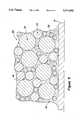
- FIG. 5is a simplified enlarged pictorial illustration of the cross-section of a solder paste body formed in accordance with the invention.
- FIG. 6is a sectional view illustrating a solder paste of the invention formed on pads of a substrate
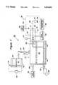
- FIG. 7is a pictorial illustration of the presently preferred apparatus for forming solder particles with precisely controlled diameters in accordance with the invention.
- FIG. 8is a pictorial illustration of the preferred method of forming of solder balls in accordance with the invention.
- the presently preferred apparatus for forming spherical solder particles in accordance with the inventionis illustrated in FIGS. 7 and 8.
- the apparatusoperates by producing and ejecting spherically-shaped bodies of liquid solder (solder alloy) which are caught in a receptacle or catcher and includes a preload reservoir 42 for initially receiving and holding liquid solder or solder alloy 44.
- Heating element 46is operatively positioned in preload reservoir 42 to heat the solder or solder alloy 44 in the reservoir 42.
- Thermocouple 48(or other temperature monitoring device) is mounted to sense the temperature of liquid solder 44 and is connected to power source 50. The output of the thermocouple is used to control the output of power source 50 which, in turn, controls heating element 46 to maintain the solder 44 at the required temperature and in a liquid state.
- An ejection chamber 52is connected to the outlet of preload reservoir 42 through conduit 54 and valve 56 to allow liquid solder 44 to flow from the preload reservoir 42 into ejection chamber 52. Oxides and impurities tend to stay at the top of the liquid solder or solder alloy 44 in the preload reservoir 42 and thus do not enter the ejection chamber 52. If high purity solder alloys are used, the preload chamber may not be necessary.
- the ejection chamber 52is pressurized through inlet port 64 with an inert gas from gas source 66 which forces liquid solder 44 through filter 68 into the ejection device 70.
- the ejection chamber 52is pressurized during operation with an inert gas to eliminate any oxygen in the atmosphere above the liquid solder 44.
- a heater 72surrounds ejection device 70 and controls the temperature of the liquid solder 44 within the ejection device 70. Heater 72 is connected to power source 74. Programmable controller 76 provides activating signals to drive electronics 78 whose output causes ejection device 70, which is preferably a continuous ejection type device, to form drops 80 of liquid solder 44 from the liquid solder stream 79 ejected from orifice 71 under pressure from gas source 66.
- the liquid solder stream 79 ejected from orifice 71 of the continuous ejection device 70form drops 80 of liquid solder as a result of activating signals from drive electronics 78.
- the space between ejection device 70 and container or catcher 84is surrounded by a chamber 90 which is filled with a relatively inert gas, such as nitrogen or helium, to eliminate oxygen from the path traveled by solder drops 80.
- a gas source 82provides a flow of inert gas through the space traveled by drops 80 and occupied by the container or catcher 84.
- chamber or housing 90enclosing the path traveled by the drops 80 of liquid solder 44 and the catcher 84 further insures that drops 80 will not be subject to oxidation.
- the housing 90may be used to provide a positive gas flow from gas source 82 to outlet 92. Thus oxides and/or contaminants removed from the space will flow out outlet 92 along with the inert gas and will not be deposited on the drops 80.
- the inert atmospherealso greatly enhances formation of generally spherical drops 80 of liquid solder 44 which solidify into generally spherical solder balls 86 and are caught in container or catcher 84.
- the chamber 90must be long enough to allow the drops 80 of liquid solder to solidify before hitting catcher 84.
- ejection device 70comprises an electro-mechanical transducer (which can be piezoelectric, electromagnetic, etc.) which causes the liquid solder stream 79 to break up into drops 80 of liquid solder 44 in response to an excitation signal from drive electronics 78. Upon cooling, the drops 80 of liquid solder 44 become solidified spherical solder balls 86 which are caught in container or catcher 84.
- electro-mechanical transducerwhich can be piezoelectric, electromagnetic, etc.
- ejection device 70is precisely controlled to produce solder balls 86 which are spherical in shape and very predictably precise in diameter.
- the diameters of the resulting solder ballscan be varied as desired.
- ejection device 70has an orifice or nozzle opening 71 of about ten (10) to about sixty (60) ⁇ m in diameter and is excited with a signal from drive electronics 78 having a frequency between about five thousand (5000) to one million (1,000,000) hertz. Changes in the amount or volume (and diameter of the resulting solder balls 86) of the drop or drops 80 are controlled by the excitation frequency provided to ejection device 70 by drive electronics 78.
- solder balls 86Small changes in diameter (and volume) of the solder balls 86 require only changes in excitation frequency applied to ejection device 70 by drive electronics 78 and controlled by programmable controller 76. Large changes require changes in size of the orifice 71 in ejection device 70.
- solder balls 86can be provided which range in diameter from as small as 10 ⁇ m to as large as 80 ⁇ m.
- solder balls 86in accordance with the invention begins with placing solid solder in preload reservoir 42. Power is applied to heating element 46 to bring the temperature of the solder to its particular melting point. After the solder is melted in the preload reservoir 42, a portion thereof is transferred through conduit 54 and valve 56 to ejection chamber 52 where the solder 44 is maintained liquid by heating element 58. Ejection chamber 52 is pressurized with a relatively inert gas, e.g. nitrogen or helium, at a pressure of from about ten (10) to about eighty (80) psi. The pressurized gas forces liquid solder 44 through filter 68 into ejection device 70 and out orifice 71 to form a fluid stream 79. Upon excitation of ejection device 70, drops 80 of liquid solder 44 are formed. Solder balls 86 are caught in container or catcher 84 after cooling and solidifying in the inert atmosphere.
- a relatively inert gase.g. nitrogen or helium
- Programmable controller 76can be programmed to cause ejection device 70 to provide a first number of solder balls 86 of a specific predetermined diameter and then provide a second number of solder balls 86 of another specific predetermined diameter. If desired, controller 76 can be programmed to cause ejection device 70 to form a third or more numbers of solder balls 86 of other specific predetermined diameters. It will be appreciated that many different predetermined diameters of solder balls 86 may be produced if desired.
- programmable controller 76can be programmed to cause the frequency of the output signal from the drive electronics 78 to sweep or vary in a predetermined manner across a range of frequencies.
- the frequencycould be caused to sweep, in a linear manner, between about 5,000 hertz to about 1,000,000 hertz or between any two frequencies between 5,000 hertz and 1,000,000 hertz.
- the resulting production of solder balls 86will include balls with diameters which vary from about 40 ⁇ m to about 50 ⁇ m when the frequency was swept between about 20,000 hertz and about 30,000 hertz. The number of solder balls 86 with diameters about a certain value would depend, of course, upon the manner and speed of the sweep of the excitation signal to ejection device 70.
- Solder pasteis made in accordance with the invention by selecting the amount, preferrably by weight, of solder balls 86 having a diameter which has been determined to be optimum for a particular application of paste. It will be appreciated that the amount of solder balls 86 may comprise a combination of solder balls 86 of different diameters and of different alloys. The solder balls 86 are then mixed with the amount of vehicle or fluid carrier determined to be optimum for the particular application.
- the fluid carrierdepending upon the application, could include a combination of rosin or derivatives thereof, an organic solvent, a thixotropic agent, an active hydrogen-containing compound, diluents, polymers, flux, etc.
- Conventional solder pastescomprise about 85% to 95% by weight of metal particles (solder alloy) and about 5% to 15% by weight of vehicle or carrier.
- solder paste 10is positioned between leads 12 of a surface mount device and pads 14 on a substrate 16.
- the solder paste 10holds the leads 12 of the surface mount device in place until reflow occurs to bond the leads 12 to pads 14.
- the curves of FIG. 4illustrate distribution of solder particles or balls of three different diameters for use in solder paste which may be readily provided with the present invention.
- Distribution curve 20shows a quantity of solder particles or balls having a diameter less than 20 ⁇ m with a very narrow distribution of different diameters.
- Distribution curve 22shows a quantity of solder particles or balls having a diameter of about 32 ⁇ m with a very narrow distribution of different diameters.
- Distribution curve 24shows a quantity of solder particles or balls having a diameter about 60 ⁇ m with a very narrow distribution of different diameters. It will be appreciated that FIG. 4 shows only solder particles or balls of three different exemplary diameters and that the present invention can provide solder particles or balls for solder paste with diameters ranging from about 10 ⁇ m to about 80 ⁇ m with precise control.
- FIG. 5shows solder paste 30 made with solder particles or balls 32, 34 and 36 of different diameters disposed in a carrier 38.
- solder balls 32could have the diameter distribution shown in distribution curve 20; solder balls 34 could have the diameter distribution shown in distribution curve 22; and solder balls 36 could have the diameter distribution shown in distribution curve 24.
- a solder paste 30 prepared in accordance with the present invention and positioned on pads 14 on substrate 16is illustrated in FIG. 6.
- solder pastes 30with solder balls of only one diameter or with various combinations of solder balls of different diameters. Because the diameters of the solder balls are precisely controlled, the solder balls can be chosen to develop solder pastes which are tailored for a specific application. Furthermore, the different diameter solder balls may be made of the same metal alloy or of different metal alloys. The solder ball diameters can be chosen to increase or to decrease the total weight percent of solder in the solder paste; to improve the application thereof; and to allow a precise modification of the final alloy composition, etc.
- Solder balls produced in accordance with the inventioncan be alloys of at least two metals selected from the group consisting of tin, bismuth, nickel, cobalt, cadmium, antimony, indium, lead, silver, gallium, aluminum, germanium, silicon and gold. Solder alloys may be eutectic alloys but eutectic compositions are not required.
- the fluid carrier or vehicle 38can be any of several compositions which may include, but not limited to, rosins or derivatives thereof, organic solvents, thixotropic agents, active hydrogen-containing compounds, diluents, polymers, flux, etc.
- the present inventionprovides improved solder pastes by 1) making metal particles or solder balls which are of precise and accurate diameter; 2) making metal particles or solder balls which are of precise and accurate but different diameters; 3) making metal particles or solder balls which are of precise and accurate diameter without substantial surface oxidation thereon.
Landscapes
- Engineering & Computer Science (AREA)
- Chemical & Material Sciences (AREA)
- Nanotechnology (AREA)
- Manufacturing & Machinery (AREA)
- Microelectronics & Electronic Packaging (AREA)
- Mechanical Engineering (AREA)
- Electric Connection Of Electric Components To Printed Circuits (AREA)
Abstract
Description
Claims (43)
Priority Applications (1)
| Application Number | Priority Date | Filing Date | Title |
|---|---|---|---|
| US08/197,750US5411602A (en) | 1994-02-17 | 1994-02-17 | Solder compositions and methods of making same |
Applications Claiming Priority (1)
| Application Number | Priority Date | Filing Date | Title |
|---|---|---|---|
| US08/197,750US5411602A (en) | 1994-02-17 | 1994-02-17 | Solder compositions and methods of making same |
Publications (1)
| Publication Number | Publication Date |
|---|---|
| US5411602Atrue US5411602A (en) | 1995-05-02 |
Family
ID=22730618
Family Applications (1)
| Application Number | Title | Priority Date | Filing Date |
|---|---|---|---|
| US08/197,750Expired - LifetimeUS5411602A (en) | 1994-02-17 | 1994-02-17 | Solder compositions and methods of making same |
Country Status (1)
| Country | Link |
|---|---|
| US (1) | US5411602A (en) |
Cited By (29)
| Publication number | Priority date | Publication date | Assignee | Title |
|---|---|---|---|---|
| US5736074A (en)* | 1995-06-30 | 1998-04-07 | Micro Fab Technologies, Inc. | Manufacture of coated spheres |
| US5772106A (en)* | 1995-12-29 | 1998-06-30 | Microfab Technologies, Inc. | Printhead for liquid metals and method of use |
| US5861323A (en)* | 1994-06-06 | 1999-01-19 | Microfab Technologies, Inc. | Process for manufacturing metal ball electrodes for a semiconductor device |
| US5877580A (en)* | 1996-12-23 | 1999-03-02 | Regents Of The University Of California | Micromachined chemical jet dispenser |
| US5891212A (en)* | 1997-07-14 | 1999-04-06 | Aeroquip Corporation | Apparatus and method for making uniformly |
| US5988480A (en)* | 1997-12-12 | 1999-11-23 | Micron Technology, Inc. | Continuous mode solder jet apparatus |
| DE19830057C1 (en)* | 1998-06-29 | 2000-03-16 | Juergen Schulze | Method and device for the pressure-free production of soft solder powder |
| US6565342B1 (en) | 2000-11-17 | 2003-05-20 | Accurus Scientific Co. Ltd. | Apparatus for making precision metal spheres |
| US20040209453A1 (en)* | 1994-07-20 | 2004-10-21 | Fujitsu Limited | Integrated electronic device having flip-chip connection with circuit board and fabrication method thereof |
| US20040217150A1 (en)* | 2000-10-06 | 2004-11-04 | Thorsten Teutsch | Method for ablating points of contact (debumping) |
| US6814778B1 (en) | 1997-12-12 | 2004-11-09 | Micron Technology, Inc. | Method for continuous mode solder jet apparatus |
| US20050243144A1 (en)* | 2004-04-09 | 2005-11-03 | Synergy Innovations, Inc. | System and method of manufacturing mono-sized-disbursed spherical particles |
| EP1623791A2 (en) | 2004-08-03 | 2006-02-08 | W.C. Heraeus GmbH | Procédé de raffinage et de répartition homogène de composants d'alliage, ainsi que d'élimination de produits de réaction indésirés et de scories dans un alliage de soudure tendre, lors de la production de poudre de soudure fine. |
| US20060267183A1 (en)* | 2005-04-22 | 2006-11-30 | International Rectifier Corporation | Use of solder paste for heat dissipation |
| US20070164089A1 (en)* | 2006-01-19 | 2007-07-19 | Nordson Corporation | Method of dispensing small amounts of liquid material |
| US20080124568A1 (en)* | 2006-07-26 | 2008-05-29 | Eric Duchesne | New flux composition and process for use thereof |
| US20100159645A1 (en)* | 1998-09-01 | 2010-06-24 | Sony Corporation | Semiconductor apparatus and process of production thereof |
| US20100223975A1 (en)* | 2008-03-03 | 2010-09-09 | Keith Lueck | Calibration and Accuracy Check System for a Breath Tester |
| US20120280593A1 (en)* | 2009-11-20 | 2012-11-08 | Epcos Ag | Solder Material for Fastening an Outer Electrode on a Piezoelectric Component and Piezoelectric Component Comprising a Solder Material |
| WO2012150105A1 (en)* | 2011-04-08 | 2012-11-08 | Micronic Mydata AB | Composition of solid-containing paste |
| US20130032934A1 (en)* | 2011-08-01 | 2013-02-07 | Tessera Inc. | Packaged microelectronic elements having blind vias for heat dissipation |
| US20140150929A1 (en)* | 2011-04-08 | 2014-06-05 | Micronic Mydata AB | Composition of solid-containing paste |
| WO2014204125A1 (en) | 2013-06-17 | 2014-12-24 | (주)라미나 | Particle production device and particle production method using same |
| US20150068713A1 (en)* | 2012-03-26 | 2015-03-12 | Erbslöh Aluminium Gmbh | Solder Powder |
| US9579738B2 (en) | 2011-02-25 | 2017-02-28 | International Business Machines Corporation | Flux composition and techniques for use thereof |
| DE102015224974A1 (en)* | 2015-12-11 | 2017-06-14 | Forschungsinstitut Für Anorganische Werkstoffe - Glas Keramik Gmbh | Method and apparatus for producing sinterable material-containing microspheres |
| US9815149B2 (en) | 2011-02-25 | 2017-11-14 | International Business Machines Corporation | Flux composition and techniques for use thereof |
| US10161835B1 (en) | 2014-11-20 | 2018-12-25 | National Technology & Engineering Solutions Of Sandia, Llc | Microsampler and method of making the same |
| JPWO2021206096A1 (en)* | 2020-04-06 | 2021-10-14 |
Citations (4)
| Publication number | Priority date | Publication date | Assignee | Title |
|---|---|---|---|---|
| US3986899A (en)* | 1974-06-07 | 1976-10-19 | Scm Corporation | Atomized copper brazing paste |
| US5147448A (en)* | 1990-10-01 | 1992-09-15 | Nuclear Metals, Inc. | Techniques for producing fine metal powder |
| US5171360A (en)* | 1990-08-30 | 1992-12-15 | University Of Southern California | Method for droplet stream manufacturing |
| US5259593A (en)* | 1990-08-30 | 1993-11-09 | University Of Southern California | Apparatus for droplet stream manufacturing |
- 1994
- 1994-02-17USUS08/197,750patent/US5411602A/ennot_activeExpired - Lifetime
Patent Citations (4)
| Publication number | Priority date | Publication date | Assignee | Title |
|---|---|---|---|---|
| US3986899A (en)* | 1974-06-07 | 1976-10-19 | Scm Corporation | Atomized copper brazing paste |
| US5171360A (en)* | 1990-08-30 | 1992-12-15 | University Of Southern California | Method for droplet stream manufacturing |
| US5259593A (en)* | 1990-08-30 | 1993-11-09 | University Of Southern California | Apparatus for droplet stream manufacturing |
| US5147448A (en)* | 1990-10-01 | 1992-09-15 | Nuclear Metals, Inc. | Techniques for producing fine metal powder |
Cited By (66)
| Publication number | Priority date | Publication date | Assignee | Title |
|---|---|---|---|---|
| US5861323A (en)* | 1994-06-06 | 1999-01-19 | Microfab Technologies, Inc. | Process for manufacturing metal ball electrodes for a semiconductor device |
| US20040209453A1 (en)* | 1994-07-20 | 2004-10-21 | Fujitsu Limited | Integrated electronic device having flip-chip connection with circuit board and fabrication method thereof |
| US6077380A (en)* | 1995-06-30 | 2000-06-20 | Microfab Technologies, Inc. | Method of forming an adhesive connection |
| US5736074A (en)* | 1995-06-30 | 1998-04-07 | Micro Fab Technologies, Inc. | Manufacture of coated spheres |
| US5772106A (en)* | 1995-12-29 | 1998-06-30 | Microfab Technologies, Inc. | Printhead for liquid metals and method of use |
| US6325271B1 (en) | 1996-12-13 | 2001-12-04 | Micron Technology, Inc. | Continuous mode solder jet apparatus |
| US5877580A (en)* | 1996-12-23 | 1999-03-02 | Regents Of The University Of California | Micromachined chemical jet dispenser |
| US6083454A (en)* | 1997-07-14 | 2000-07-04 | Aeroquip Corporation | Apparatus and method for making uniformly sized and shaped spheres |
| US5891212A (en)* | 1997-07-14 | 1999-04-06 | Aeroquip Corporation | Apparatus and method for making uniformly |
| USRE39224E1 (en)* | 1997-07-14 | 2006-08-08 | Alpha Metals (Korea) Ltd. | Apparatus and method for making uniformly sized and shaped spheres |
| US20040026479A1 (en)* | 1997-12-12 | 2004-02-12 | Farnworth Warren M. | Continuous mode solder jet apparatus |
| US20070068996A1 (en)* | 1997-12-12 | 2007-03-29 | Farnworth Warren M | Continuous mode solder jet apparatus |
| US6443350B2 (en) | 1997-12-12 | 2002-09-03 | Micron Technology, Inc. | Continuous mode solder jet apparatus |
| US7159752B2 (en) | 1997-12-12 | 2007-01-09 | Micron Technology, Inc. | Continuous mode solder jet apparatus |
| US6588645B2 (en) | 1997-12-12 | 2003-07-08 | Micron Technology, Inc. | Continuous mode solder jet apparatus |
| US6082605A (en)* | 1997-12-12 | 2000-07-04 | Micron Technology, Inc. | Continuous mode solder jet apparatus |
| US20060163318A1 (en)* | 1997-12-12 | 2006-07-27 | Farnworth Warren M | Continuous mode solder jet apparatus and method |
| US6350494B1 (en) | 1997-12-12 | 2002-02-26 | Micron Technology, Inc. | Method for generating continuous stream of liquid metal droplets |
| US5988480A (en)* | 1997-12-12 | 1999-11-23 | Micron Technology, Inc. | Continuous mode solder jet apparatus |
| US6960373B2 (en) | 1997-12-12 | 2005-11-01 | Micron Technology, Inc. | Continuous mode solder jet method |
| US6814778B1 (en) | 1997-12-12 | 2004-11-09 | Micron Technology, Inc. | Method for continuous mode solder jet apparatus |
| DE19830057C1 (en)* | 1998-06-29 | 2000-03-16 | Juergen Schulze | Method and device for the pressure-free production of soft solder powder |
| US20100159645A1 (en)* | 1998-09-01 | 2010-06-24 | Sony Corporation | Semiconductor apparatus and process of production thereof |
| US20040217150A1 (en)* | 2000-10-06 | 2004-11-04 | Thorsten Teutsch | Method for ablating points of contact (debumping) |
| US7481352B2 (en)* | 2000-10-06 | 2009-01-27 | Pac Tech-Packaging Technologies Gmbh | Method for ablating points of contact (debumping) |
| US6613124B2 (en) | 2000-11-17 | 2003-09-02 | Accurus Scientific Co., Ltd. | Method of making precision metal spheres |
| US20060156863A1 (en)* | 2000-11-17 | 2006-07-20 | Chow Hubert K | Process of fabricating metal spheres |
| US7097687B2 (en) | 2000-11-17 | 2006-08-29 | Accurus Scientific Co., Ltd. | Process for fabricating metal spheres |
| US20040055417A1 (en)* | 2000-11-17 | 2004-03-25 | Chow Hubert K. | Process for fabricating metal spheres |
| US6565342B1 (en) | 2000-11-17 | 2003-05-20 | Accurus Scientific Co. Ltd. | Apparatus for making precision metal spheres |
| US7588622B2 (en) | 2000-11-17 | 2009-09-15 | Henkel Of America, Inc. | Process of fabricating metal spheres |
| US20080210054A1 (en)* | 2000-11-17 | 2008-09-04 | Chow Hubert K | Process of Fabricating Metal Spheres |
| US7422619B2 (en) | 2000-11-17 | 2008-09-09 | Accurus Scientific Co., Ltd. | Process of fabricating metal spheres |
| US20050243144A1 (en)* | 2004-04-09 | 2005-11-03 | Synergy Innovations, Inc. | System and method of manufacturing mono-sized-disbursed spherical particles |
| US20060208042A1 (en)* | 2004-08-03 | 2006-09-21 | Walter Protsch | Method for refining and homogeneously distributing alloying partners and for removing undesirable reaction products and slags in or from soft solder during the production of fine solder powder |
| EP1623791A2 (en) | 2004-08-03 | 2006-02-08 | W.C. Heraeus GmbH | Procédé de raffinage et de répartition homogène de composants d'alliage, ainsi que d'élimination de produits de réaction indésirés et de scories dans un alliage de soudure tendre, lors de la production de poudre de soudure fine. |
| US7331498B2 (en) | 2004-08-03 | 2008-02-19 | W. C. Heraeus Gmbh | Method for refining and homogeneously distributing alloying partners and for removing undesirable reaction products and slags in or from soft solder during the production of fine solder powder |
| WO2006116225A3 (en)* | 2005-04-22 | 2007-03-29 | Int Rectifier Corp | The use of solder paste for heat dissipation |
| US20060267183A1 (en)* | 2005-04-22 | 2006-11-30 | International Rectifier Corporation | Use of solder paste for heat dissipation |
| US7417312B2 (en)* | 2005-04-22 | 2008-08-26 | International Rectifier Corporation | Use of solder paste for heat dissipation |
| US20070164089A1 (en)* | 2006-01-19 | 2007-07-19 | Nordson Corporation | Method of dispensing small amounts of liquid material |
| US20080124568A1 (en)* | 2006-07-26 | 2008-05-29 | Eric Duchesne | New flux composition and process for use thereof |
| US7780801B2 (en) | 2006-07-26 | 2010-08-24 | International Business Machines Corporation | Flux composition and process for use thereof |
| US8444774B2 (en) | 2006-07-26 | 2013-05-21 | International Business Machines Corporation | Flux composition and process for use thereof |
| US8713985B2 (en) | 2008-03-03 | 2014-05-06 | Alcotek, Inc. | Calibration and accuracy check system |
| US20100223975A1 (en)* | 2008-03-03 | 2010-09-09 | Keith Lueck | Calibration and Accuracy Check System for a Breath Tester |
| US8418523B2 (en) | 2008-03-03 | 2013-04-16 | Keith Lueck | Calibration and accuracy check system for a breath tester |
| US20120280593A1 (en)* | 2009-11-20 | 2012-11-08 | Epcos Ag | Solder Material for Fastening an Outer Electrode on a Piezoelectric Component and Piezoelectric Component Comprising a Solder Material |
| US8823245B2 (en)* | 2009-11-20 | 2014-09-02 | Epcos Ag | Solder material for fastening an outer electrode on a piezoelectric component and piezoelectric component comprising a solder material |
| US9808874B2 (en) | 2011-02-25 | 2017-11-07 | International Business Machines Corporation | Flux composition and techniques for use thereof |
| US9579738B2 (en) | 2011-02-25 | 2017-02-28 | International Business Machines Corporation | Flux composition and techniques for use thereof |
| US9815149B2 (en) | 2011-02-25 | 2017-11-14 | International Business Machines Corporation | Flux composition and techniques for use thereof |
| WO2012150105A1 (en)* | 2011-04-08 | 2012-11-08 | Micronic Mydata AB | Composition of solid-containing paste |
| US20140150929A1 (en)* | 2011-04-08 | 2014-06-05 | Micronic Mydata AB | Composition of solid-containing paste |
| US9975206B2 (en)* | 2011-04-08 | 2018-05-22 | Micronic Mydata AB | Composition of solid-containing paste |
| US20130032934A1 (en)* | 2011-08-01 | 2013-02-07 | Tessera Inc. | Packaged microelectronic elements having blind vias for heat dissipation |
| US8618647B2 (en)* | 2011-08-01 | 2013-12-31 | Tessera, Inc. | Packaged microelectronic elements having blind vias for heat dissipation |
| US9620433B2 (en) | 2011-08-01 | 2017-04-11 | Tessera, Inc. | Packaged microelectronic elements having blind vias for heat dissipation |
| US20170207141A1 (en)* | 2011-08-01 | 2017-07-20 | Tessera, Inc. | Packaged microelectronic elements having blind vias for heat dissipation |
| US20150068713A1 (en)* | 2012-03-26 | 2015-03-12 | Erbslöh Aluminium Gmbh | Solder Powder |
| WO2014204125A1 (en) | 2013-06-17 | 2014-12-24 | (주)라미나 | Particle production device and particle production method using same |
| US10005062B2 (en) | 2013-06-17 | 2018-06-26 | Laminar Co., Ltd | Apparatus for manufacturing particles and method for manufacturing particles using the same |
| US10161835B1 (en) | 2014-11-20 | 2018-12-25 | National Technology & Engineering Solutions Of Sandia, Llc | Microsampler and method of making the same |
| DE102015224974A1 (en)* | 2015-12-11 | 2017-06-14 | Forschungsinstitut Für Anorganische Werkstoffe - Glas Keramik Gmbh | Method and apparatus for producing sinterable material-containing microspheres |
| JPWO2021206096A1 (en)* | 2020-04-06 | 2021-10-14 | ||
| WO2021206096A1 (en)* | 2020-04-06 | 2021-10-14 | 昭和電工マテリアルズ株式会社 | Solder particles, production method for solder particles, and substrate with solder particles |
Similar Documents
| Publication | Publication Date | Title |
|---|---|---|
| US5411602A (en) | Solder compositions and methods of making same | |
| US5736074A (en) | Manufacture of coated spheres | |
| US5229016A (en) | Method and apparatus for dispensing spherical-shaped quantities of liquid solder | |
| US5415679A (en) | Methods and apparatus for forming microdroplets of liquids at elevated temperatures | |
| US5193738A (en) | Methods and apparatus for soldering without using flux | |
| US6015083A (en) | Direct solder bumping of hard to solder substrate | |
| US5377902A (en) | Method of making solder interconnection arrays | |
| US5275330A (en) | Solder ball connect pad-on-via assembly process | |
| USRE39224E1 (en) | Apparatus and method for making uniformly sized and shaped spheres | |
| US5855323A (en) | Method and apparatus for jetting, manufacturing and attaching uniform solder balls | |
| US5643353A (en) | Controlling depoling and aging of piezoelectric transducers | |
| US20090057378A1 (en) | In-situ chip attachment using self-organizing solder | |
| WO2006126564A1 (en) | Lead-free solder paste | |
| JP2004107728A (en) | Joining material and joining method | |
| US5861323A (en) | Process for manufacturing metal ball electrodes for a semiconductor device | |
| US7422973B2 (en) | Method for forming multi-layer bumps on a substrate | |
| JP3353814B2 (en) | Apparatus and method for enhancing stability of dispensed molten solder droplets | |
| US6596094B2 (en) | Solder paste and electronic device | |
| CN113798722A (en) | Composite soldering paste and method for preparing BGA (ball grid array) soldering ball/soldering point with fine-grain beta-Sn crystal grains by applying composite soldering paste | |
| CN100501955C (en) | Solder composition and bump forming method using the same | |
| EP1357197B1 (en) | Minute copper balls and a method for their manufacture | |
| JP2013132654A (en) | Solder paste | |
| JP2001267730A (en) | Solder ball | |
| JP2001226706A (en) | Apparatus for manufacturing fine metallic ball | |
| US20060021466A1 (en) | Mixed alloy lead-free solder paste |
Legal Events
| Date | Code | Title | Description |
|---|---|---|---|
| AS | Assignment | Owner name:MICROFAB TECHNOLOGIES, INC., TEXAS Free format text:ASSIGNMENT OF ASSIGNORS INTEREST;ASSIGNOR:HAYES, DONALD J.;REEL/FRAME:006892/0597 Effective date:19940210 | |
| STCF | Information on status: patent grant | Free format text:PATENTED CASE | |
| CC | Certificate of correction | ||
| FPAY | Fee payment | Year of fee payment:4 | |
| RR | Request for reexamination filed | Effective date:20010802 | |
| FEPP | Fee payment procedure | Free format text:PAYER NUMBER DE-ASSIGNED (ORIGINAL EVENT CODE: RMPN); ENTITY STATUS OF PATENT OWNER: SMALL ENTITY Free format text:PAYOR NUMBER ASSIGNED (ORIGINAL EVENT CODE: ASPN); ENTITY STATUS OF PATENT OWNER: SMALL ENTITY | |
| FPAY | Fee payment | Year of fee payment:8 | |
| B1 | Reexamination certificate first reexamination | Free format text:CLAIMS 1-43 ARE CANCELLED. NEW CLAIMS 44-53 ARE ADDED AND DETERMINED TO BE PATENTABLE. | |
| FEPP | Fee payment procedure | Free format text:PAYER NUMBER DE-ASSIGNED (ORIGINAL EVENT CODE: RMPN); ENTITY STATUS OF PATENT OWNER: SMALL ENTITY Free format text:PAYOR NUMBER ASSIGNED (ORIGINAL EVENT CODE: ASPN); ENTITY STATUS OF PATENT OWNER: SMALL ENTITY | |
| FPAY | Fee payment | Year of fee payment:12 |