US5411513A - Transmission mechanism for a surgical cutting instrument - Google Patents
Transmission mechanism for a surgical cutting instrumentDownload PDFInfo
- Publication number
- US5411513A US5411513AUS08/201,277US20127794AUS5411513AUS 5411513 AUS5411513 AUS 5411513AUS 20127794 AUS20127794 AUS 20127794AUS 5411513 AUS5411513 AUS 5411513A
- Authority
- US
- United States
- Prior art keywords
- cam
- channel
- cutting blade
- motor
- drive
- Prior art date
- Legal status (The legal status is an assumption and is not a legal conclusion. Google has not performed a legal analysis and makes no representation as to the accuracy of the status listed.)
- Expired - Lifetime
Links
- 230000005540biological transmissionEffects0.000titleclaimsabstractdescription23
- 230000007246mechanismEffects0.000titleabstractdescription13
- 230000033001locomotionEffects0.000claimsabstractdescription26
- 238000003780insertionMethods0.000claimsdescription4
- 230000037431insertionEffects0.000claimsdescription4
- 230000004323axial lengthEffects0.000claims1
- 210000001519tissueAnatomy0.000description17
- 238000000034methodMethods0.000description5
- 238000001356surgical procedureMethods0.000description4
- 239000000463materialSubstances0.000description3
- 238000007789sealingMethods0.000description3
- 238000013461designMethods0.000description2
- 239000012530fluidSubstances0.000description2
- 230000013011matingEffects0.000description2
- 238000012986modificationMethods0.000description2
- 230000004048modificationEffects0.000description2
- 229910001220stainless steelInorganic materials0.000description2
- 239000010935stainless steelSubstances0.000description2
- 229910000984420 stainless steelInorganic materials0.000description1
- 229920004943Delrin®Polymers0.000description1
- FAPWRFPIFSIZLT-UHFFFAOYSA-MSodium chlorideChemical compound[Na+].[Cl-]FAPWRFPIFSIZLT-UHFFFAOYSA-M0.000description1
- 230000001133accelerationEffects0.000description1
- 230000009471actionEffects0.000description1
- 230000004075alterationEffects0.000description1
- 238000013459approachMethods0.000description1
- 210000000988bone and boneAnatomy0.000description1
- 230000003247decreasing effectEffects0.000description1
- 230000007850degenerationEffects0.000description1
- 230000004927fusionEffects0.000description1
- 210000000232gallbladderAnatomy0.000description1
- 208000014674injuryDiseases0.000description1
- 238000012977invasive surgical procedureMethods0.000description1
- 230000002262irrigationEffects0.000description1
- 238000003973irrigationMethods0.000description1
- 210000003127kneeAnatomy0.000description1
- 239000000314lubricantSubstances0.000description1
- 230000001737promoting effectEffects0.000description1
- 210000002307prostateAnatomy0.000description1
- 230000009467reductionEffects0.000description1
- 238000005096rolling processMethods0.000description1
- 239000011780sodium chlorideSubstances0.000description1
- 238000013519translationMethods0.000description1
- 230000008733traumaEffects0.000description1
Images


Classifications
- A—HUMAN NECESSITIES
- A61—MEDICAL OR VETERINARY SCIENCE; HYGIENE
- A61B—DIAGNOSIS; SURGERY; IDENTIFICATION
- A61B17/00—Surgical instruments, devices or methods
- A61B17/32—Surgical cutting instruments
- A61B17/320016—Endoscopic cutting instruments, e.g. arthroscopes, resectoscopes
- A61B17/32002—Endoscopic cutting instruments, e.g. arthroscopes, resectoscopes with continuously rotating, oscillating or reciprocating cutting instruments
- A—HUMAN NECESSITIES
- A61—MEDICAL OR VETERINARY SCIENCE; HYGIENE
- A61B—DIAGNOSIS; SURGERY; IDENTIFICATION
- A61B17/00—Surgical instruments, devices or methods
- A61B17/00234—Surgical instruments, devices or methods for minimally invasive surgery
- A61B2017/00238—Type of minimally invasive operation
- A61B2017/00261—Discectomy
Definitions
- the present inventionrelates to a percutaneous or intratrocar surgical instrument for the excision and removal of a wide range of tissues. More particularly, a surgical cutting instrument is disclosed which is particularly adapted for a wide range of operating speeds and which is capable of cutting tough tissue, such as may be found during orthopaedic or spinal surgery.
- the present inventionhas application in a wide range of procedures, although the following disclosures will pertain principally to minimally invasive cutting instruments used in the orthopaedic or spinal surgical fields.
- the present disclosurespecifically addresses a transmission mechanism for converting, in one embodiment, rotary output from a motor to linear reciprocation of the cutting blade.
- the Onik devicelike other known devices, is a "tube within a tube" cutting instrument which incorporates a reciprocating inner cutting sleeve operating within the central bore of an outer cutting sleeve.
- the excised disk materialis suspended in a saline irrigation fluid which is aspirated through the central passageway of the inner cutting sleeve.
- tissue cutting instrumentspresently available in the art suffer from a variety of problems.
- rotary cuttershave a tendency to become clogged as the excised tissue "spools" or winds around the shaft driving the rotating cutter blade. This spooling can clog the aspiration channel of the cutter and even stall the blade or motor.
- the drive motors for such devicestend to be larger than rotary motors. It can certainly by appreciated that one consideration in the design of a percutaneous surgical cutting instrument is the size of the device. The surgeon must be able to deftly manipulate the cutting instrument while performing a procedure such as a discectomy. It is therefore an important design criterion that the cutting instrument fill as small an envelope as possible, a criterion that is more easily fulfilled by the use of a rotary motor.
- the cutting instrumentmust be capable of excising the tissue cleanly, without tearing, and of aspirating the tissue pieces efficiently and without clogging.
- the instrumentmust also be efficiently packaged and smaller than a typical reciprocating cutting instrument.
- a transmission and drive mechanismwhich can convert rotary drive movement to reciprocating movement of the cutting blade.
- the use of a rotary motorcan permit higher torques in a smaller package than may be achieved by a reciprocating motor of comparable output power and input energy requirements. Consequently, in accordance with the invention, a cam is provided that engages the spindle of the motor.
- the camis generally cylindrical in shape with a cam channel defined in the outer surface of the cam barrel.
- a drive ballrides within the channel and is supported within a boss of a linear in-line driver.
- the in-line driverreciprocates within a bearing supported by a driver cartridge. Pressure between the drive ball and the cam channel is maintained by a set screw threaded into the boss in the in-line driver.
- the spindlewhich is engaged to the cam, rotates the cam.
- the rotation of the cam and cam barrelcauses the cam channel to pass underneath the drive ball, which forces the drive ball to follow the channel path.
- the channel pathis in the form of a harmonic curve so that the drive ball will reciprocate through a particular stroke during a full rotation of the cam.
- the cam channelcan assume a variety of paths around the circumference of the cam barrel. One such path would multiply the number of reciprocations for one revolution of the cam barrel.
- FIG. 1is a partial cutaway view of the portion of a surgical cutting instrument housing the cutting blade driven by the transmission and drive mechanism of the present invention.
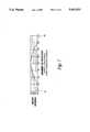
- FIG. 2is a side cross-sectional view of the transmission and drive mechanism for use in connection with the cutting instrument depicted in FIG. 1.
- FIG. 3is an enlarged cross-sectional view of the cam incorporated into the transmission and drive mechanism shown in FIG. 2.
- FIG. 4is an end elevational view of the cam shown in FIG. 3.
- FIG. 5is a graph illustrating the cam relationship between rotation of the drive motor and linear stroke of the cutting blade.
- FIG. 6is a graph illustrating an alternative cam relationship between motor rotation and linear stroke of the cutting blade in which the blade reciprocates through two cycles for a single revolution of the motor and cam.
- FIG. 7is a graph illustrating an alternative cam relationship between motor rotation and linear stroke of the cutting blade in which the blade dwells at a predetermined point in its cycle.
- FIG. 1A portion of a surgical cutting instrument 10 is shown in FIG. 1 which is adapted for percutaneous insertion at the surgical site and is specifically adapted to cut tissue in the spinal region.
- the same instrumentcould be used in other orthopaedic, such as an arthroscopic surgery of the knee, or similar surgical procedures, such as removal of the gall bladder or prostate.
- FIG. 1depicts only the cutting portion of the instrument, this portion being engaged to a transmission and drive portion described herein.
- the instrument 10includes a hand piece 11 which supports an outer cannula 13.
- the outer cannulahas a blunt distal tip 15 to minimize trauma to tissue as the cutting instrument is manipulated in the surgical site.
- the outer cannula 13includes a cutting opening 14 formed therethrough which opens to a central bore 16 extending through the length of the cannula 13.
- the cutting opening 14defines a cutting edge 18, which in one embodiment is defined by a beveled cut in the wall of the outer cannula.
- the cutting opening 14is in the shape of an isosceles triangle.
- the cutting edge 18 in the specific embodimentis defined at the side of the triangle, but excludes the base of the triangular shape as shown in FIG. 1.
- the cutting instrument 10further includes an inner cannula 20 which is slideably and concentrically disposed within the outer cannula 13.
- the inner cannula 20terminates in a cutting edge 22 at the end opening 23 of the cannula.
- the end opening 23opens into an aspiration passageway 25 extending through the entire length of the inner cannula 20.
- the outer cannula 13is supported by the hand piece 11, while the inner cannula 20 also extends into the hand piece 11 to engage a drive mount 30 at a cannula support portion 33.
- the drive mountis engaged to a drive rod 31 that is connected to a motor or suitable mechanism for providing reciprocating motion. Specifically, the drive rod 31 and mount 30 reciprocates axially in the direction of the arrows R shown in FIG. 1. Since the inner cannula 20 is fixed to the drive mount 30 it too reciprocates within the outer cannula 13. As the inner cannula 20 reciprocates, the inner surface of the outer cannula and the outer surface of the inner cannula operate as a bearing surface for the smooth movement of the inner cannula.
- the drive mount 30can include an aspiration chamber 34 which is connected through an aspiration tube 36 to a suitable vacuum source and tissue collection chamber in a manner well known in the art.
- the aspiration tube 36is engaged to the reciprocating drive mount 30.
- This aspectrequires the definition of a slot 38 in the hand piece 11 to allow the tube 36 room to move as it reciprocates with the drive mount.
- the instrument 10incorporates many features of known reciprocating cutters, particularly those implementing the "tube within a tube” approach. It is understood that other reciprocating cutter portions are contemplated, the foregoing being provided for illustrative purposes.
- the present inventioncontemplates a transmission and drive portion for providing reciprocating motion to the drive rod 31. It is understood that the disclosed transmission and drive portion could be adapted to impart reciprocating movement to the cutter 20 using a number of interfaces that may or may not include a drive rod 31.
- FIG. 2One embodiment of this transmission and drive portion is depicted in FIG. 2.
- a transmission and drive portion 50is shown which can be suitably engaged to the cutting portion of the surgical cutting instrument 10 shown in FIG. 1.
- the transmission and drive portion 50includes a driver cover 51 which houses the transmission and drive mechanism of the assembly.
- a driver cartridge 52is affixed to the open end of the driver cover 51.
- a pair of sealing O-rings 61are disposed between the driver cartridge 52 and the driver cover 51. These sealing O-rings provide, in one aspect, a means for removably engaging the cartridge 52 to the cover 51 in a press fit relationship. This relationship facilitates assembly of the device and disassembly to service the movable components of the transmission and drive mechanism housed therein.
- the driver cover 51supports a motor 54, which in the preferred illustrated embodiment is a rotary motor. Specifically, the motor 54 provides a rotational driving force through its drive spindle 55.
- the motor 54is supported within the driver cover 51 by way of a motor cap 56, which is attached to the motor by a number of screws 57.
- a power cable 58supplies electrical current to the monitor.
- the power cable 58is supported on the driver cover 51 by a strain relief collet assembly 59 engaged at one end of the cover.
- the driver cartridge 52is attached to the motor cap 56 by a pair of cartridge mounting screws 60.
- the driver cover 51is supported by the cartridge 52 through the seal ring 61.
- This particular configurationthat is the arrangement of driver cover 51, cartridge 52 and the motor 54 and its power components, facilitates assembly of the complete transmission and drive portion.
- the motor drive spindle 55can be first engaged to the motor 54 by way of the screws 57.
- the cap 56is then attached to the driver cartridge 52 by way of the screws 60.
- the power cable 58can be threaded through the collet assembly 59 and the driver cover 51 and attached to the motor, with the driver cover situated downstream on the power cable.
- the collet assembly 59 and driver cover 51can be slid along the power cable until the driver cover achieves its press fit engagement with the sealing O-rings 61 and the driver cartridge 52.
- the collet assembly 59can then be tightened to clamp the power cable to the driver cover 51. Disassembly can be readily achieved by reversing the above described steps.
- the driver cartridge 52supports a linear in-line bearing 65.
- the bearingcan be adhered to the inner bore of the driver cartridge 52.
- the bearingcan be press fit into position, or a set screw 70 can be used to clamp the in-line bearing 65 to the driver cartridge 52, as depicted in FIG. 2.
- This linear in-line bearing 65is generally cylindrical in shape, with a recess portion 66 formed in one side for purposes described herein.
- An access bore 67is formed in the driver cartridge 52 which aligns with the boss recess 66 of the in-line bearing 65.
- the in-line bearingdefines a central bore 68 and an outer surface 69 which contacts the driver cartridge 52.
- an in-line driver 75Reciprocatably disposed within the in-line bearing 65 is an in-line driver 75.
- This driverincludes at its free end an engagement clip 76 which can be suitably configured to engage a mating portion attached to the drive rod 31 of the cutter portion of the instrument 10, as shown in FIG. 1.
- Many such engagement mechanismscan be utilized that can accomplish a quick attachment and disconnect capability.
- the in-line driver 75includes a boss 77 projecting outwardly therefrom. This boss 77 is adapted to reciprocate within the boss recess 66 in the in-line bearing 65. At its free end, the in-line driver 75 is connected to the driver cartridge 52 by way of a flex ring seal 78. As the in-line driver 75 reciprocates in the direction of the arrows 79, the flex ring seal 78 expands and contracts accordingly, while continuously maintaining a tight seal between the cutting portion of the instrument and the transmission and drive portion 50 of the instrument. It should be appreciated that since the cutting instrument portion shown in FIG. 1 utilizes vacuum and fluid flow, it is important to maintain a tight seal between these two portions of the cutting instrument 10.
- the reciprocating motionis imparted to the in-line driver 75 by way of a first and second cam elements which form a transmission means, or a means for converting the rotary movement of the drive spindle 55 of the motor 54 to a reciprocating movement of the in-line driver 75.
- the first cam elementis a cam 80.
- the cam 80is engaged to the motor drive spindle 55 at a cam head 81.
- the cam head 81includes a spindle bore 82 which is sized to closely receive the drive spindle 55 therein.
- a dowel bore 83Transverse to the spindle bore 82 is a dowel bore 83 which intersects or overlaps a portion of the spindle bore 82.
- a tapered dowel 84is inserted into the dowel bore 83 to bear against the drive spindle 55 when it is disposed within the spindle bore 82.
- the dowelis preferably slightly shorter than the length of the dowel bore 83. It is understood that the taper of the dowel facilitates its insertion into the bore and particularly its passage across the drive spindle 55 to form the press fit clamping engagement.
- the cam 80includes a cam channel 85 carved into the outer surface of the cam barrel 89.
- This cam channelis preferably cut into the barrel 89 in the form of a circular segment less than a semi-circle so that the channel receives only a lower portion of a cam follower, which in the preferred embodiment is a drive ball 86.
- this drive ballis substantially housed within the boss 77 of the in-line driver 75, which constitutes the second cam element of the transmission means.
- the set screw 87presses against the drive ball to maintain its contact within the cam channel 85. It is understood that other cam channel and cam follower configurations may be contemplated. However, it is believed that the ball and channel configuration is optimal to reduce friction and wear between the components.
- the cam 80is rotatably supported not only by the drive spindle 55 of the motor 54, but also by a shielded ball bearing 90, which bearing is supported between the driver cartridge 52 and the cam barrel 89.
- a snap ring groove 88can be provided in the cam barrel 89 to further lock the cam into position within the driver cartridge 52.
- the rotary motion imparted by the motor 54 to the drive spindle 55is directly translated to the cam 80 by its press fit engagement.
- the cam channel 85transverses directly beneath the drive ball 86.
- the cam channelis more than simply a circumferential channel cutting through a plane perpendicular to the axis of the cam 80. More particularly, the channel has a harmonic shape so that portions of the channel at 180° opposite locations are displaced from each other axially along the length of the barrel. Specifically, as shown in FIGS. 3 and 5, the portion of the channel at location or apex 85a is axially offset by 0.254 cm. from location or apex 85b that is offset by 180° around the cam barrel.
- cam channel 85can have various configurations. It has, however, been found for the preferred embodiment that a simple harmonic curve provides the smoothest and most efficient translation of the rotary motion of the motor 54 to the reciprocating motion of the cutting blade shown in FIG. 1. It should also be appreciated that greater linear strokes can be achieved by offsetting the 180° opposite apexes of the cam channel by a greater dimension than that shown in FIG. 5. This would, of course slightly skew the motion curve and modify the acceleration of the cutting blade at various points in the rotation of the cam 80.
- a single revolution of the camproduces a single forward and return stroke of the cutting blade.
- Multiplication of the reciprocating speedcan be achieved by providing more than two apexes to the cam channel 85, as depicted in the graph of FIG. 6. It can therefore be seen that several cams could be provided that would be readily removed and replaced within the transmission and drive portion 50 of the cutting instrument 10. When greater cutting speeds are required, a cam having a cam channel with several apexes could be provided. It can be expected, however, that the actual cutting force that would be imparted at the higher cutting speeds would be decreased even as the speeds are increased. Conversely, a reduction in the reciprocating speed would increase the actual cutting power achieved by the blade, which may be necessary when operating on tougher tissues.
- the cam channelcan be configured as depicted in the graph of FIG. 7.
- the cam channelincludes a dwell region 95 in the ranges 0°-45° and 315°-360°.
- this dwell region 95the cam channel will not include any axial offset component so that the cam follower will not stroke in the linear direction.
- These dwell regionswill result in a dwell in the movement of the cutter blade, which in the embodiment depicted in FIG. 7 occurs at the beginning of the stroke.
- This dwell region 95can be provided, for example, to allow greater amounts of tissue to be drawn into the cutting opening 14 of the instrument before the cutter is advanced to slice the tissue.
- the dwell regioncould be arranged at any portion of the cutter stroke depending upon the perceived needs of the cutting instrument.
- the camitself is approximately 28.5 cm long.
- the offset of the 180° apexes 85a and 85b of the cam channelare approximately 2.54 cm.
- the cam 80is preferably formed of 420 stainless steel, as is the drive ball 86. It is believed that the stainless steel mating surfaces provide a better wear resistant rolling surface to translate the rotary motion to reciprocating motion. Naturally, certain biocompatible lubricants could be applied between the drive ball and the cam channel.
- the inline bearing 65can be formed of a plastic such as delrin or other material that exhibits suitable wear characteristics when supporting a component such as the inline driver 75.
- the driver 75may also be formed of a plastic or stainless steel.
- the first cam element, or the cam 80can be engaged to the engagement clip 76, and the inline driver 75 can be configured to engaged the motor drive spindle 55. In this orientation, rotary motion is transmitted through rotation of the driver 75, through the ball 80 and to the channel 85 of the cam barrel 89. Since the driver 75 in this configuration is essentially fixed to linear movement, the cam 80 must necessarily reciprocate as it is acted upon by the ball 80.
Landscapes
- Health & Medical Sciences (AREA)
- Surgery (AREA)
- Life Sciences & Earth Sciences (AREA)
- Biomedical Technology (AREA)
- Nuclear Medicine, Radiotherapy & Molecular Imaging (AREA)
- Engineering & Computer Science (AREA)
- Orthopedic Medicine & Surgery (AREA)
- Heart & Thoracic Surgery (AREA)
- Medical Informatics (AREA)
- Molecular Biology (AREA)
- Animal Behavior & Ethology (AREA)
- General Health & Medical Sciences (AREA)
- Public Health (AREA)
- Veterinary Medicine (AREA)
- Surgical Instruments (AREA)
Abstract
Description
Claims (9)
Priority Applications (3)
| Application Number | Priority Date | Filing Date | Title |
|---|---|---|---|
| US08/201,277US5411513A (en) | 1994-02-24 | 1994-02-24 | Transmission mechanism for a surgical cutting instrument |
| PCT/US1995/002358WO1995022935A1 (en) | 1994-02-24 | 1995-02-24 | Transmission mechanism for a surgical cutting instrument |
| AU18830/95AAU1883095A (en) | 1994-02-24 | 1995-02-24 | Transmission mechanism for a surgical cutting instrument |
Applications Claiming Priority (1)
| Application Number | Priority Date | Filing Date | Title |
|---|---|---|---|
| US08/201,277US5411513A (en) | 1994-02-24 | 1994-02-24 | Transmission mechanism for a surgical cutting instrument |
Publications (1)
| Publication Number | Publication Date |
|---|---|
| US5411513Atrue US5411513A (en) | 1995-05-02 |
Family
ID=22745204
Family Applications (1)
| Application Number | Title | Priority Date | Filing Date |
|---|---|---|---|
| US08/201,277Expired - LifetimeUS5411513A (en) | 1994-02-24 | 1994-02-24 | Transmission mechanism for a surgical cutting instrument |
Country Status (3)
| Country | Link |
|---|---|
| US (1) | US5411513A (en) |
| AU (1) | AU1883095A (en) |
| WO (1) | WO1995022935A1 (en) |
Cited By (103)
| Publication number | Priority date | Publication date | Assignee | Title |
|---|---|---|---|---|
| US5873885A (en)* | 1996-08-29 | 1999-02-23 | Storz Instrument Company | Surgical handpiece |
| EP0949881A4 (en)* | 1996-08-29 | 2001-04-11 | Bausch & Lomb Surgical Inc | Surgical handpiece |
| US6245084B1 (en) | 1998-10-20 | 2001-06-12 | Promex, Inc. | System for controlling a motor driven surgical cutting instrument |
| US6258054B1 (en) | 1997-03-11 | 2001-07-10 | Microaire Surgical Instruments, Inc. | Power assisted liposuction and lipoinjection equipment |
| DE20107842U1 (en) | 2001-05-09 | 2001-08-02 | Franz Jakoubek Medizintechnik GmbH, 78576 Emmingen-Liptingen | Surgical tubular shaft instrument |
| EP1201210A1 (en)* | 2000-10-23 | 2002-05-02 | Alcon Grieshaber AG | Apparatus for ophtalmology |
| US6478681B1 (en) | 2000-11-27 | 2002-11-12 | Duke University | Magnetic couplings for imparting simultaneous rotary and longitudinal oscillations |
| US6494892B1 (en) | 1998-10-20 | 2002-12-17 | Suros Surgical Systems, Inc. | Disposable hub for a surgical cutting instrument |
| US6517560B1 (en) | 2000-11-27 | 2003-02-11 | Duke University | Hand-held surgical instruments employing magnetic couplings for simultaneous rotary and longitudinal oscillations of distal workpieces |
| US6638235B2 (en) | 2000-11-06 | 2003-10-28 | Suros Surgical Systems, Inc. | Biopsy apparatus |
| US20040049128A1 (en)* | 2000-11-06 | 2004-03-11 | Miller Michael E. | Biopsy apparatus |
| US6743305B2 (en)* | 2001-10-23 | 2004-06-01 | General Electric Company | High-strength high-toughness precipitation-hardened steel |
| US20040122459A1 (en)* | 2002-09-27 | 2004-06-24 | Harp Richard J. | Shielded reciprocating surgical file |
| WO2005020826A1 (en)* | 2003-09-03 | 2005-03-10 | Hee Young Lee | Surgical handpiece equipped with couplings for suction and saline solution |
| US20060200155A1 (en)* | 2002-09-27 | 2006-09-07 | Harp Richard J | Surgical file instrument |
| US20060260994A1 (en)* | 2005-05-18 | 2006-11-23 | Mark Joseph L | Selectively openable tissue filter |
| US20070010738A1 (en)* | 2004-10-14 | 2007-01-11 | Mark Joseph L | Surgical site marker delivery system |
| US20070041863A1 (en)* | 2001-12-11 | 2007-02-22 | Sandvik Intellectual Property Ab | Precipitation hardenable austenitic steel |
| US20070055259A1 (en)* | 2005-08-17 | 2007-03-08 | Norton Britt K | Apparatus and methods for removal of intervertebral disc tissues |
| US20070162062A1 (en)* | 2005-12-08 | 2007-07-12 | Norton Britt K | Reciprocating apparatus and methods for removal of intervertebral disc tissues |
| US20080200833A1 (en)* | 2003-10-14 | 2008-08-21 | Hardin Terry D | Vacuum assisted biopsy device |
| US20080221481A1 (en)* | 2003-10-14 | 2008-09-11 | Mark Joseph L | Vacuum assisted biopsy needle set |
| US7458940B2 (en) | 2000-11-06 | 2008-12-02 | Suros Surgical Systems, Inc. | Biopsy apparatus |
| US20090087249A1 (en)* | 2007-10-01 | 2009-04-02 | Jake Flagle | Adapter assembly |
| US20100152758A1 (en)* | 2008-12-16 | 2010-06-17 | Mark Joseph L | Tissue removal device for neurosurgical and spinal surgery applications |
| US20100152614A1 (en)* | 2008-12-16 | 2010-06-17 | Mark Joseph L | Tissue removal device for neurosurgical and spinal surgery applications |
| US20100152756A1 (en)* | 2008-12-16 | 2010-06-17 | Mark Joseph L | Tissue removal device for neurosurgical and spinal surgery applications |
| US20100152760A1 (en)* | 2008-12-16 | 2010-06-17 | Mark Joseph L | Tissue removal device for neurosurgical and spinal surgery applications |
| US20100152761A1 (en)* | 2008-12-16 | 2010-06-17 | Mark Joseph L | Tissue removal device for neurosurgical and spinal surgery applications |
| US20100152533A1 (en)* | 2008-12-16 | 2010-06-17 | Mark Joseph L | Tissue removal device for use with imaging devices in neurosurgical and spinal surgery applications |
| US20100152762A1 (en)* | 2008-12-16 | 2010-06-17 | Mark Joseph L | Tissue removal system with multi-directional foot actuator assembly for neurosurgical and spinal surgery applications |
| US20100152615A1 (en)* | 2008-12-16 | 2010-06-17 | Mark Joseph L | Tissue removal device with adjustable fluid supply sleeve for neurosurgical and spinal surgery applications |
| US20100160777A1 (en)* | 2008-12-22 | 2010-06-24 | Hardin Terry D | Reverse deployment device |
| US20100160818A1 (en)* | 2005-04-12 | 2010-06-24 | Ethicon Endo-Surgery, Inc. | MRI Biopsy Device |
| US20100249817A1 (en)* | 2008-12-16 | 2010-09-30 | Mark Joseph L | Positioning system for tissue removal device |
| US20110004119A1 (en)* | 2009-07-01 | 2011-01-06 | Michael Hoffa | Surgical system |
| US20110066154A1 (en)* | 2009-09-17 | 2011-03-17 | David Narducci | Surgical File Instrument Construction with Mechanism to Convert Rotary Motion to Reciprocal Motion |
| US20110071527A1 (en)* | 2009-09-24 | 2011-03-24 | Medicinelodge, Inc. Dba Imds Co-Innovation | Surgical rasping systems and mehtods |
| US20110118542A1 (en)* | 2009-08-05 | 2011-05-19 | Cucin Robert L | Method of and apparatus for treating abdominal obesity, metabolic syndrome and type ii diabetes mellitus in human patients |
| US20110230904A1 (en)* | 2001-10-26 | 2011-09-22 | Smith & Nephew, Inc. | Reciprocating rotary arthroscopic surgical instrument |
| US8048003B2 (en) | 2003-10-14 | 2011-11-01 | Suros Surgical Systems, Inc. | Vacuum assisted biopsy device |
| US8808200B2 (en) | 2007-10-01 | 2014-08-19 | Suros Surgical Systems, Inc. | Surgical device and method of using same |
| US8893722B2 (en) | 1997-09-04 | 2014-11-25 | Smith & Nephew, Inc. | Surgical endoscopic cutting device and method for its use |
| US9005203B2 (en) | 2009-09-24 | 2015-04-14 | Imds, Llc | Reciprocating surgical instruments |
| US9033986B2 (en) | 2009-09-24 | 2015-05-19 | Imds, Llc | Reciprocating surgical instrument |
| US9125550B2 (en) | 2004-08-27 | 2015-09-08 | Smith & Nephew, Inc. | Tissue resecting system |
| US20150258333A1 (en)* | 2013-03-15 | 2015-09-17 | The Spectranetics Corporation | Medical device for removing an implanted object |
| US9155454B2 (en) | 2010-09-28 | 2015-10-13 | Smith & Nephew, Inc. | Hysteroscopic system |
| US9198675B2 (en) | 2009-09-24 | 2015-12-01 | Imds Llc | Reciprocating surgical instrument |
| US9279751B2 (en) | 2008-12-16 | 2016-03-08 | Nico Corporation | System and method of taking and collecting tissue cores for treatment |
| US9504247B2 (en) | 2008-12-16 | 2016-11-29 | Nico Corporation | System for collecting and preserving tissue cores |
| US20170035404A1 (en)* | 2015-04-24 | 2017-02-09 | Invuity, Inc. | Surgical instrument compatible with operating room equipment |
| US9638770B2 (en) | 2004-05-21 | 2017-05-02 | Devicor Medical Products, Inc. | MRI biopsy apparatus incorporating an imageable penetrating portion |
| US9668765B2 (en) | 2013-03-15 | 2017-06-06 | The Spectranetics Corporation | Retractable blade for lead removal device |
| US9795365B2 (en) | 2004-05-21 | 2017-10-24 | Devicor Medical Products, Inc. | MRI biopsy apparatus incorporating a sleeve and multi-function obturator |
| US9808275B2 (en) | 2006-12-22 | 2017-11-07 | The Spectranetics Corporation | Retractable separating systems and methods |
| US9820480B2 (en) | 2008-12-16 | 2017-11-21 | Nico Corporation | System for collecting and preserving tissue cores |
| USD806245S1 (en) | 2015-02-20 | 2017-12-26 | The Spectranetics Corporation | Medical device handle |
| US9925366B2 (en) | 2013-03-15 | 2018-03-27 | The Spectranetics Corporation | Surgical instrument for removing an implanted object |
| US9925314B2 (en) | 2009-08-05 | 2018-03-27 | Rocin Laboratories, Inc. | Method of performing intra-abdominal tissue aspiration to ameliorate the metabolic syndrome, or abdominal obesity |
| US9931105B2 (en) | 2008-12-16 | 2018-04-03 | Nico Corporation | System and method of taking and collecting tissue cores for treatment |
| US9980743B2 (en) | 2013-03-15 | 2018-05-29 | The Spectranetics Corporation | Medical device for removing an implanted object using laser cut hypotubes |
| US10080578B2 (en) | 2008-12-16 | 2018-09-25 | Nico Corporation | Tissue removal device with adjustable delivery sleeve for neurosurgical and spinal surgery applications |
| US10136913B2 (en) | 2013-03-15 | 2018-11-27 | The Spectranetics Corporation | Multiple configuration surgical cutting device |
| US10299803B2 (en) | 2016-08-04 | 2019-05-28 | Covidien Lp | Self-aligning drive coupler |
| US10299819B2 (en) | 2016-07-28 | 2019-05-28 | Covidien Lp | Reciprocating rotary surgical cutting device and system for tissue resecting, and method for its use |
| US10368890B2 (en) | 2008-12-16 | 2019-08-06 | Nico Corporation | Multi-functional surgical device for neurosurgical and spinal surgery applications |
| US10448999B2 (en) | 2013-03-15 | 2019-10-22 | The Spectranetics Corporation | Surgical instrument for removing an implanted object |
| US10631889B2 (en) | 2014-12-16 | 2020-04-28 | Covidien Lp | Surgical device with incorporated tissue extraction |
| US10750931B2 (en) | 2015-05-26 | 2020-08-25 | Covidien Lp | Systems and methods for generating a fluid bearing for an operative procedure |
| US10772654B2 (en) | 2017-03-02 | 2020-09-15 | Covidien Lp | Fluid-driven tissue resecting instruments, systems, and methods |
| US10772652B2 (en) | 2015-01-28 | 2020-09-15 | Covidien Lp | Tissue resection system |
| US10804769B2 (en) | 2015-06-17 | 2020-10-13 | Covidien Lp | Surgical instrument with phase change cooling |
| US10799264B2 (en) | 2015-06-18 | 2020-10-13 | Covidien Lp | Surgical instrument with suction control |
| US10842350B2 (en) | 2015-06-17 | 2020-11-24 | Covidien Lp | Endoscopic device with drip flange and methods of use thereof for an operative procedure |
| US10842532B2 (en) | 2013-03-15 | 2020-11-24 | Spectranetics Llc | Medical device for removing an implanted object |
| US10869684B2 (en) | 2018-02-13 | 2020-12-22 | Covidien Lp | Powered tissue resecting device |
| US10898218B2 (en) | 2019-02-25 | 2021-01-26 | Covidien Lp | Tissue resecting device including a motor cooling assembly |
| US10945752B2 (en) | 2019-03-20 | 2021-03-16 | Covidien Lp | Tissue resecting instrument including a rotation lock feature |
| US11065147B2 (en) | 2018-10-18 | 2021-07-20 | Covidien Lp | Devices, systems, and methods for pre-heating fluid to be introduced into a patient during a surgical procedure |
| US11083481B2 (en) | 2019-02-22 | 2021-08-10 | Covidien Lp | Tissue resecting instrument including an outflow control seal |
| US11154318B2 (en) | 2019-02-22 | 2021-10-26 | Covidien Lp | Tissue resecting instrument including an outflow control seal |
| US11179172B2 (en) | 2019-12-05 | 2021-11-23 | Covidien Lp | Tissue resecting instrument |
| US20210367478A1 (en)* | 2013-06-26 | 2021-11-25 | Corindus, Inc. | Differential Drive |
| US11197710B2 (en) | 2018-10-26 | 2021-12-14 | Covidien Lp | Tissue resecting device including a blade lock and release mechanism |
| US11317947B2 (en) | 2020-02-18 | 2022-05-03 | Covidien Lp | Tissue resecting instrument |
| US11342707B2 (en)* | 2017-10-30 | 2022-05-24 | U-Shin Deutschland Zugangssysteme Gmbh | Strain relief for a cable harness |
| US11376032B2 (en) | 2019-12-05 | 2022-07-05 | Covidien Lp | Tissue resecting instrument |
| US11452806B2 (en) | 2019-10-04 | 2022-09-27 | Covidien Lp | Outflow collection vessels, systems, and components thereof for hysteroscopic surgical procedures |
| US11547782B2 (en) | 2020-01-31 | 2023-01-10 | Covidien Lp | Fluid collecting sheaths for endoscopic devices and systems |
| US11547815B2 (en) | 2018-05-30 | 2023-01-10 | Covidien Lp | Systems and methods for measuring and controlling pressure within an internal body cavity |
| US11553977B2 (en) | 2019-05-29 | 2023-01-17 | Covidien Lp | Hysteroscopy systems and methods for managing patient fluid |
| US11571233B2 (en) | 2020-11-19 | 2023-02-07 | Covidien Lp | Tissue removal handpiece with integrated suction |
| US11596429B2 (en) | 2020-04-20 | 2023-03-07 | Covidien Lp | Tissue resecting instrument |
| US11737777B2 (en) | 2020-02-05 | 2023-08-29 | Covidien Lp | Tissue resecting instruments |
| US11864735B2 (en) | 2016-05-26 | 2024-01-09 | Covidien Lp | Continuous flow endoscope |
| US11883058B2 (en) | 2019-03-26 | 2024-01-30 | Covidien Lp | Jaw members, end effector assemblies, and ultrasonic surgical instruments including the same |
| US11890237B2 (en) | 2019-10-04 | 2024-02-06 | Covidien Lp | Outflow collection vessels, systems, and components thereof for hysteroscopic surgical procedures |
| US12053203B2 (en) | 2014-03-03 | 2024-08-06 | Spectranetics, Llc | Multiple configuration surgical cutting device |
| US12156673B2 (en) | 2020-10-07 | 2024-12-03 | Covidien Lp | Temperature measurement device for a handpiece of a surgical instrument |
| CN119498921A (en)* | 2024-12-05 | 2025-02-25 | 广东精美医疗科技有限公司 | Medical plastic surgery reciprocating saw bending machine |
| US12303109B2 (en) | 2021-12-22 | 2025-05-20 | Covidien Lp | Surgical systems and methods for component cooling while warming fluid to be introduced during a surgical procedure |
| US12364500B2 (en) | 2021-05-26 | 2025-07-22 | Covidien Lp | Tissue resecting instrument |
Citations (6)
| Publication number | Priority date | Publication date | Assignee | Title |
|---|---|---|---|---|
| US4210146A (en)* | 1978-06-01 | 1980-07-01 | Anton Banko | Surgical instrument with flexible blade |
| US4246906A (en)* | 1979-06-28 | 1981-01-27 | Winberg Jack S | Apparatus for self-monitoring of physiological variables |
| US4589414A (en)* | 1983-04-27 | 1986-05-20 | Olympus Optical Co., Ltd. | Surgical cutting instrument |
| US4753234A (en)* | 1986-11-03 | 1988-06-28 | Miguel Martinez | Surgical cutting instrument having a offset probe for ophthalmic surgery |
| US5059204A (en)* | 1989-10-26 | 1991-10-22 | Site Microsurgical Systems, Inc. | Ocular cutter with enhanced cutting action |
| US5201749A (en)* | 1990-09-19 | 1993-04-13 | Sachse Rainer E | Circularly oscillating saw |
- 1994
- 1994-02-24USUS08/201,277patent/US5411513A/ennot_activeExpired - Lifetime
- 1995
- 1995-02-24WOPCT/US1995/002358patent/WO1995022935A1/enactiveSearch and Examination
- 1995-02-24AUAU18830/95Apatent/AU1883095A/ennot_activeAbandoned
Patent Citations (6)
| Publication number | Priority date | Publication date | Assignee | Title |
|---|---|---|---|---|
| US4210146A (en)* | 1978-06-01 | 1980-07-01 | Anton Banko | Surgical instrument with flexible blade |
| US4246906A (en)* | 1979-06-28 | 1981-01-27 | Winberg Jack S | Apparatus for self-monitoring of physiological variables |
| US4589414A (en)* | 1983-04-27 | 1986-05-20 | Olympus Optical Co., Ltd. | Surgical cutting instrument |
| US4753234A (en)* | 1986-11-03 | 1988-06-28 | Miguel Martinez | Surgical cutting instrument having a offset probe for ophthalmic surgery |
| US5059204A (en)* | 1989-10-26 | 1991-10-22 | Site Microsurgical Systems, Inc. | Ocular cutter with enhanced cutting action |
| US5201749A (en)* | 1990-09-19 | 1993-04-13 | Sachse Rainer E | Circularly oscillating saw |
Cited By (229)
| Publication number | Priority date | Publication date | Assignee | Title |
|---|---|---|---|---|
| EP0949881A4 (en)* | 1996-08-29 | 2001-04-11 | Bausch & Lomb Surgical Inc | Surgical handpiece |
| US5873885A (en)* | 1996-08-29 | 1999-02-23 | Storz Instrument Company | Surgical handpiece |
| US6258054B1 (en) | 1997-03-11 | 2001-07-10 | Microaire Surgical Instruments, Inc. | Power assisted liposuction and lipoinjection equipment |
| US8893722B2 (en) | 1997-09-04 | 2014-11-25 | Smith & Nephew, Inc. | Surgical endoscopic cutting device and method for its use |
| US9750520B2 (en) | 1997-09-04 | 2017-09-05 | Covidien Lp | Surgical endoscopic cutting device and method for its use |
| US9089358B2 (en) | 1997-09-04 | 2015-07-28 | Smith & Nephew, Inc. | Surgical cutting device and method for its use |
| US9226765B2 (en) | 1997-09-04 | 2016-01-05 | Smith & Nephew, Inc. | Surgical cutting device and method for its use |
| US9226650B2 (en) | 1997-09-04 | 2016-01-05 | Smith & Nephew, Inc. | Surgical cutting device and method for its use |
| US9427247B2 (en) | 1997-09-04 | 2016-08-30 | Smith & Nephew, Inc. | Surgical cutting device and method for its use |
| US6358263B2 (en) | 1998-10-20 | 2002-03-19 | Promex, Inc. | System for controlling a motor driven surgical cutting instrument |
| US6494892B1 (en) | 1998-10-20 | 2002-12-17 | Suros Surgical Systems, Inc. | Disposable hub for a surgical cutting instrument |
| US6245084B1 (en) | 1998-10-20 | 2001-06-12 | Promex, Inc. | System for controlling a motor driven surgical cutting instrument |
| EP1201210A1 (en)* | 2000-10-23 | 2002-05-02 | Alcon Grieshaber AG | Apparatus for ophtalmology |
| US6527736B1 (en) | 2000-10-23 | 2003-03-04 | Grieshaber & Co. Ag Schaffhausen | Device for use in ophthalmologic procedures |
| US8109886B2 (en) | 2000-11-06 | 2012-02-07 | Suros Surgical Systems, Inc. | Biopsy apparatus |
| US20070027407A1 (en)* | 2000-11-06 | 2007-02-01 | Suros Surgical Systems, Inc. | Biopsy apparatus with vacuum relief |
| US20040267157A1 (en)* | 2000-11-06 | 2004-12-30 | Miller Michael E | Biopsy apparatus |
| US20050049521A1 (en)* | 2000-11-06 | 2005-03-03 | Suros Surgical Systems, Inc. | Collection filter for biopsy apparatus |
| US20090137927A1 (en)* | 2000-11-06 | 2009-05-28 | Miller Michael E | Biopsy apparatus with vacuum relief |
| US20050113715A1 (en)* | 2000-11-06 | 2005-05-26 | Jeffrey Schwindt | Biopsy apparatus |
| US8277393B2 (en) | 2000-11-06 | 2012-10-02 | Suros Surgical Systems, Inc. | Biopsy apparatus |
| US7883476B2 (en) | 2000-11-06 | 2011-02-08 | Suros Surgical Systems, Inc. | Selectively detachable outer cannula hub |
| US20040049128A1 (en)* | 2000-11-06 | 2004-03-11 | Miller Michael E. | Biopsy apparatus |
| US6638235B2 (en) | 2000-11-06 | 2003-10-28 | Suros Surgical Systems, Inc. | Biopsy apparatus |
| US20060155209A1 (en)* | 2000-11-06 | 2006-07-13 | Miller Michael E | Selectively detachable outer cannula hub |
| US8568332B2 (en) | 2000-11-06 | 2013-10-29 | Suros Surgical Systems, Inc. | Biopsy apparatus |
| US7458940B2 (en) | 2000-11-06 | 2008-12-02 | Suros Surgical Systems, Inc. | Biopsy apparatus |
| US8167818B2 (en) | 2000-11-06 | 2012-05-01 | Suros Surgical Systems, Inc. | Biopsy apparatus with vacuum relief |
| US8192370B2 (en) | 2000-11-06 | 2012-06-05 | Suros Surgical Systems, Inc. | Biopsy apparatus |
| US7497833B2 (en) | 2000-11-06 | 2009-03-03 | Suros Surgical Systems, Inc. | Biopsy apparatus with vacuum relief |
| US6758824B1 (en) | 2000-11-06 | 2004-07-06 | Suros Surgical Systems, Inc. | Biopsy apparatus |
| US20090048533A1 (en)* | 2000-11-06 | 2009-02-19 | Miller Michael E | Biopsy apparatus |
| US8986222B2 (en) | 2000-11-06 | 2015-03-24 | Hologic, Inc. | Biopsy apparatus |
| US7837630B2 (en) | 2000-11-06 | 2010-11-23 | Suros Surgical Systems, Inc. | Fluid control element for biopsy apparatus |
| US8764679B2 (en) | 2000-11-06 | 2014-07-01 | Suros Surgical Systems, Inc. | Biopsy apparatus |
| US6478681B1 (en) | 2000-11-27 | 2002-11-12 | Duke University | Magnetic couplings for imparting simultaneous rotary and longitudinal oscillations |
| US6517560B1 (en) | 2000-11-27 | 2003-02-11 | Duke University | Hand-held surgical instruments employing magnetic couplings for simultaneous rotary and longitudinal oscillations of distal workpieces |
| DE20107842U1 (en) | 2001-05-09 | 2001-08-02 | Franz Jakoubek Medizintechnik GmbH, 78576 Emmingen-Liptingen | Surgical tubular shaft instrument |
| US6743305B2 (en)* | 2001-10-23 | 2004-06-01 | General Electric Company | High-strength high-toughness precipitation-hardened steel |
| US8663264B2 (en) | 2001-10-26 | 2014-03-04 | Smith & Nephew, Inc. | Reciprocating rotary arthroscopic surgical instrument |
| US9060801B1 (en) | 2001-10-26 | 2015-06-23 | Smith & Nephew, Inc. | Reciprocating rotary arthroscopic surgical instrument |
| US9060800B1 (en) | 2001-10-26 | 2015-06-23 | Smith & Nephew, Inc. | Reciprocating rotary arthroscopic surgical instrument |
| US9066745B2 (en) | 2001-10-26 | 2015-06-30 | Smith & Nephew, Inc. | Reciprocating rotary arthroscopic surgical instrument |
| US9636130B2 (en) | 2001-10-26 | 2017-05-02 | Covidien Lp | Reciprocating rotary arthroscopic surgical instrument |
| US10441306B2 (en) | 2001-10-26 | 2019-10-15 | Covidien Lp | Reciprocating rotary arthroscopic surgical instrument |
| US20110230904A1 (en)* | 2001-10-26 | 2011-09-22 | Smith & Nephew, Inc. | Reciprocating rotary arthroscopic surgical instrument |
| US20070041863A1 (en)* | 2001-12-11 | 2007-02-22 | Sandvik Intellectual Property Ab | Precipitation hardenable austenitic steel |
| US8080011B2 (en) | 2002-09-27 | 2011-12-20 | Surgitech, L.L.C. | Reciprocating cutting tool |
| US20060058732A1 (en)* | 2002-09-27 | 2006-03-16 | Harp Richard J | Pump system |
| US20130331842A1 (en)* | 2002-09-27 | 2013-12-12 | Surgitech, Llc | Reciprocating cutting tool |
| US20040122459A1 (en)* | 2002-09-27 | 2004-06-24 | Harp Richard J. | Shielded reciprocating surgical file |
| US7390330B2 (en)* | 2002-09-27 | 2008-06-24 | Surgitech, Llc | Reciprocating surgical file |
| US8672834B2 (en) | 2002-09-27 | 2014-03-18 | Surgitech, Llc | Surgical file system |
| US20080058820A1 (en)* | 2002-09-27 | 2008-03-06 | Harp Richard J | Reciprocating cutting tool |
| US20060200154A1 (en)* | 2002-09-27 | 2006-09-07 | Harp Richard J | Surgical file system with fluid system |
| US8100823B2 (en) | 2002-09-27 | 2012-01-24 | Surgitech, Llc | Surgical file system with a visualization instrument |
| US20060200153A1 (en)* | 2002-09-27 | 2006-09-07 | Harp Richard J | Surgical assembly for tissue removal |
| EP1549199A4 (en)* | 2002-09-27 | 2010-08-25 | Surgitech Llc | Shielded reciprocating surgical file |
| US8545502B2 (en) | 2002-09-27 | 2013-10-01 | Surgitech, Llc | Reciprocating cutting tool |
| US7837700B2 (en) | 2002-09-27 | 2010-11-23 | Surgitech, Llc | Drive apparatus |
| US7837687B2 (en) | 2002-09-27 | 2010-11-23 | Surgitech, Llc | Surgical assembly for tissue removal |
| JP2006500998A (en)* | 2002-09-27 | 2006-01-12 | サージファイル,インク. | Shielded reciprocating surgical file |
| US20060200155A1 (en)* | 2002-09-27 | 2006-09-07 | Harp Richard J | Surgical file instrument |
| US20060079919A1 (en)* | 2002-09-27 | 2006-04-13 | Harp Richard J | Drive apparatus |
| US7666186B2 (en) | 2002-09-27 | 2010-02-23 | Surgitech, Llc | Surgical system with a blade |
| WO2005020826A1 (en)* | 2003-09-03 | 2005-03-10 | Hee Young Lee | Surgical handpiece equipped with couplings for suction and saline solution |
| US7988642B2 (en) | 2003-10-14 | 2011-08-02 | Suros Surgical Systems, Inc. | Vacuum assisted biopsy device |
| US20080200833A1 (en)* | 2003-10-14 | 2008-08-21 | Hardin Terry D | Vacuum assisted biopsy device |
| US8048003B2 (en) | 2003-10-14 | 2011-11-01 | Suros Surgical Systems, Inc. | Vacuum assisted biopsy device |
| US20080221481A1 (en)* | 2003-10-14 | 2008-09-11 | Mark Joseph L | Vacuum assisted biopsy needle set |
| US8231544B2 (en) | 2003-10-14 | 2012-07-31 | Suros Surgical Systems, Inc. | Vacuum assisted biopsy needle set |
| US8430827B2 (en) | 2003-10-14 | 2013-04-30 | Suros Surgical Sysytems, Inc. | Vacuum assisted biopsy device |
| US9392999B2 (en) | 2004-05-21 | 2016-07-19 | Devicor Medical Products, Inc. | MRI biopsy device |
| US9504453B2 (en) | 2004-05-21 | 2016-11-29 | Devicor Medical Products, Inc. | MRI biopsy device |
| US9638770B2 (en) | 2004-05-21 | 2017-05-02 | Devicor Medical Products, Inc. | MRI biopsy apparatus incorporating an imageable penetrating portion |
| US9795365B2 (en) | 2004-05-21 | 2017-10-24 | Devicor Medical Products, Inc. | MRI biopsy apparatus incorporating a sleeve and multi-function obturator |
| US8932233B2 (en) | 2004-05-21 | 2015-01-13 | Devicor Medical Products, Inc. | MRI biopsy device |
| US10076237B2 (en) | 2004-08-27 | 2018-09-18 | Covidien Lp | Tissue resecting system |
| US10939810B2 (en) | 2004-08-27 | 2021-03-09 | Covidien Lp | Tissue resecting system |
| US9936861B2 (en) | 2004-08-27 | 2018-04-10 | Covidien Lp | Tissue resecting system |
| US9125550B2 (en) | 2004-08-27 | 2015-09-08 | Smith & Nephew, Inc. | Tissue resecting system |
| US20070016017A1 (en)* | 2004-10-14 | 2007-01-18 | Mark Joseph L | Surgical site marker delivery system |
| US20070010738A1 (en)* | 2004-10-14 | 2007-01-11 | Mark Joseph L | Surgical site marker delivery system |
| US20100160818A1 (en)* | 2005-04-12 | 2010-06-24 | Ethicon Endo-Surgery, Inc. | MRI Biopsy Device |
| US20060260994A1 (en)* | 2005-05-18 | 2006-11-23 | Mark Joseph L | Selectively openable tissue filter |
| US7556622B2 (en) | 2005-05-18 | 2009-07-07 | Suros Surgical Systems, Inc. | Selectively openable tissue filter |
| US20070055259A1 (en)* | 2005-08-17 | 2007-03-08 | Norton Britt K | Apparatus and methods for removal of intervertebral disc tissues |
| US20070162062A1 (en)* | 2005-12-08 | 2007-07-12 | Norton Britt K | Reciprocating apparatus and methods for removal of intervertebral disc tissues |
| US9808275B2 (en) | 2006-12-22 | 2017-11-07 | The Spectranetics Corporation | Retractable separating systems and methods |
| US10537354B2 (en) | 2006-12-22 | 2020-01-21 | The Spectranetics Corporation | Retractable separating systems and methods |
| US8808200B2 (en) | 2007-10-01 | 2014-08-19 | Suros Surgical Systems, Inc. | Surgical device and method of using same |
| US8202229B2 (en) | 2007-10-01 | 2012-06-19 | Suros Surgical Systems, Inc. | Surgical device |
| US20090088663A1 (en)* | 2007-10-01 | 2009-04-02 | Miller Michael E | Surgical system |
| US20090088666A1 (en)* | 2007-10-01 | 2009-04-02 | Miller Michael E | Surgical device |
| US8187204B2 (en) | 2007-10-01 | 2012-05-29 | Suros Surgical Systems, Inc. | Surgical device and method for using same |
| US20090087249A1 (en)* | 2007-10-01 | 2009-04-02 | Jake Flagle | Adapter assembly |
| US9820480B2 (en) | 2008-12-16 | 2017-11-21 | Nico Corporation | System for collecting and preserving tissue cores |
| US9504247B2 (en) | 2008-12-16 | 2016-11-29 | Nico Corporation | System for collecting and preserving tissue cores |
| US8430825B2 (en) | 2008-12-16 | 2013-04-30 | Nico Corporation | Tissue removal device for neurosurgical and spinal surgery applications |
| US20100152614A1 (en)* | 2008-12-16 | 2010-06-17 | Mark Joseph L | Tissue removal device for neurosurgical and spinal surgery applications |
| US20100249817A1 (en)* | 2008-12-16 | 2010-09-30 | Mark Joseph L | Positioning system for tissue removal device |
| US8888803B2 (en) | 2008-12-16 | 2014-11-18 | Nico Corporation | Tissue removal device for neurosurgical and spinal surgery applications |
| US10080578B2 (en) | 2008-12-16 | 2018-09-25 | Nico Corporation | Tissue removal device with adjustable delivery sleeve for neurosurgical and spinal surgery applications |
| US8357175B2 (en) | 2008-12-16 | 2013-01-22 | Nico Corporation | Positioning system for tissue removal device |
| US8460327B2 (en) | 2008-12-16 | 2013-06-11 | Nico Corporation | Tissue removal device for neurosurgical and spinal surgery applications |
| US20100152756A1 (en)* | 2008-12-16 | 2010-06-17 | Mark Joseph L | Tissue removal device for neurosurgical and spinal surgery applications |
| JP2015083201A (en)* | 2008-12-16 | 2015-04-30 | ニコ・コーポレーション | Tissue removal device with adjustable fluid supply sleeve for neurosurgical and spinal surgery applications |
| US9028518B2 (en) | 2008-12-16 | 2015-05-12 | Nico Corporation | Tissue removal device for neurosurgical and spinal surgery applications |
| US10398462B2 (en) | 2008-12-16 | 2019-09-03 | Nico Corporation | Tissue removal device with adjustable sleeve for neurosurgical and spinal surgery applications |
| US9279751B2 (en) | 2008-12-16 | 2016-03-08 | Nico Corporation | System and method of taking and collecting tissue cores for treatment |
| US8657841B2 (en)* | 2008-12-16 | 2014-02-25 | Nico Corporation | Tissue removal device for neurosurgical and spinal surgery applications |
| US10048176B2 (en) | 2008-12-16 | 2018-08-14 | Nico Corporation | System and method of taking and collecting tissue cores for treatment |
| US8496599B2 (en) | 2008-12-16 | 2013-07-30 | Nico Corporation | Tissue removal device for neurosurgical and spinal surgery applications |
| US10368890B2 (en) | 2008-12-16 | 2019-08-06 | Nico Corporation | Multi-functional surgical device for neurosurgical and spinal surgery applications |
| US20100152760A1 (en)* | 2008-12-16 | 2010-06-17 | Mark Joseph L | Tissue removal device for neurosurgical and spinal surgery applications |
| US11609160B2 (en) | 2008-12-16 | 2023-03-21 | Nico Corporation | System and method of taking and collecting tissue cores for treatment |
| US20100152761A1 (en)* | 2008-12-16 | 2010-06-17 | Mark Joseph L | Tissue removal device for neurosurgical and spinal surgery applications |
| US9216031B2 (en) | 2008-12-16 | 2015-12-22 | Nico Corporation | Tissue removal device with adjustable fluid supply sleeve for neurosurgical and spinal surgery applications |
| US20100152533A1 (en)* | 2008-12-16 | 2010-06-17 | Mark Joseph L | Tissue removal device for use with imaging devices in neurosurgical and spinal surgery applications |
| US9931105B2 (en) | 2008-12-16 | 2018-04-03 | Nico Corporation | System and method of taking and collecting tissue cores for treatment |
| US8702738B2 (en) | 2008-12-16 | 2014-04-22 | Nico Corporation | Tissue removal device for neurosurgical and spinal surgery applications |
| US20100152762A1 (en)* | 2008-12-16 | 2010-06-17 | Mark Joseph L | Tissue removal system with multi-directional foot actuator assembly for neurosurgical and spinal surgery applications |
| US10959424B2 (en) | 2008-12-16 | 2021-03-30 | Nico Corporation | System for collecting and preserving tissue cores |
| US9655639B2 (en) | 2008-12-16 | 2017-05-23 | Nico Corporation | Tissue removal device for use with imaging devices in neurosurgical and spinal surgery applications |
| US20100152615A1 (en)* | 2008-12-16 | 2010-06-17 | Mark Joseph L | Tissue removal device with adjustable fluid supply sleeve for neurosurgical and spinal surgery applications |
| US20100152758A1 (en)* | 2008-12-16 | 2010-06-17 | Mark Joseph L | Tissue removal device for neurosurgical and spinal surgery applications |
| US11759259B2 (en) | 2008-12-16 | 2023-09-19 | Nico Corporation | Tissue removal device with adjustable delivery sleeve for neurosurgical and spinal surgery applications |
| WO2010077931A3 (en)* | 2008-12-16 | 2010-11-25 | Nico Corporation | Tissue removal device with adjustable fluid supply sleeve for neurosurgical and spinal surgery applications |
| US20100160777A1 (en)* | 2008-12-22 | 2010-06-24 | Hardin Terry D | Reverse deployment device |
| WO2010096139A3 (en)* | 2009-02-20 | 2011-12-01 | Nico Corporation | Tissue removal device for neurosurgical and spinal surgery applications |
| US8529468B2 (en) | 2009-07-01 | 2013-09-10 | Suros Surgical Systems, Inc. | Surgical system |
| US20110004119A1 (en)* | 2009-07-01 | 2011-01-06 | Michael Hoffa | Surgical system |
| US8858464B2 (en) | 2009-07-01 | 2014-10-14 | Suros Surgical Systems, Inc. | Surgical system |
| US8465471B2 (en) | 2009-08-05 | 2013-06-18 | Rocin Laboratories, Inc. | Endoscopically-guided electro-cauterizing power-assisted fat aspiration system for aspirating visceral fat tissue within the abdomen of a patient |
| US12178494B2 (en) | 2009-08-05 | 2024-12-31 | Rocin Laboratories, Inc | Laparoscopic-based method of safely removing visceral fat tissue deposits from within the mesenteric region of a human patient suffering from metabolic syndrome |
| US9833279B2 (en) | 2009-08-05 | 2017-12-05 | Rocin Laboratories, Inc. | Twin-cannula tissue aspiration instrument system |
| US11259862B2 (en) | 2009-08-05 | 2022-03-01 | Rocin Laboratories, Inc. | Coaxial-driven tissue aspiration instrument system |
| US12171482B2 (en) | 2009-08-05 | 2024-12-24 | Rocin Laboratories, Inc. | Bariatric surgery operating room with a laparoscopic-based visceral fat tissue aspiration system configured and operational for treating metabolic syndrome in human patients on an ambulatory basis |
| US9925314B2 (en) | 2009-08-05 | 2018-03-27 | Rocin Laboratories, Inc. | Method of performing intra-abdominal tissue aspiration to ameliorate the metabolic syndrome, or abdominal obesity |
| US20110118542A1 (en)* | 2009-08-05 | 2011-05-19 | Cucin Robert L | Method of and apparatus for treating abdominal obesity, metabolic syndrome and type ii diabetes mellitus in human patients |
| WO2011034601A1 (en)* | 2009-09-17 | 2011-03-24 | The Anspach Effort, Inc. | Surgical file instrument construction with mechanism to convert rotary motion to reciprocal motion |
| US8388622B2 (en) | 2009-09-17 | 2013-03-05 | The Anspach Effort, Inc. | Surgical file instrument construction with mechanism to convert rotary motion to reciprocal motion |
| US20110066154A1 (en)* | 2009-09-17 | 2011-03-17 | David Narducci | Surgical File Instrument Construction with Mechanism to Convert Rotary Motion to Reciprocal Motion |
| US9033986B2 (en) | 2009-09-24 | 2015-05-19 | Imds, Llc | Reciprocating surgical instrument |
| US8617164B2 (en) | 2009-09-24 | 2013-12-31 | Imds Corporation | Surgical rasping systems and methods |
| US9198675B2 (en) | 2009-09-24 | 2015-12-01 | Imds Llc | Reciprocating surgical instrument |
| US9005203B2 (en) | 2009-09-24 | 2015-04-14 | Imds, Llc | Reciprocating surgical instruments |
| US20110071527A1 (en)* | 2009-09-24 | 2011-03-24 | Medicinelodge, Inc. Dba Imds Co-Innovation | Surgical rasping systems and mehtods |
| US9155454B2 (en) | 2010-09-28 | 2015-10-13 | Smith & Nephew, Inc. | Hysteroscopic system |
| US11229354B2 (en) | 2010-09-28 | 2022-01-25 | Covidien Lp | Hysteroscopic system |
| US10251539B2 (en) | 2010-09-28 | 2019-04-09 | Covidien Lp | Hysteroscopic system |
| US12369788B2 (en) | 2010-09-28 | 2025-07-29 | Covidien Lp | Hysteroscopic system |
| US11889993B2 (en) | 2010-09-28 | 2024-02-06 | Covidien Lp | Hysteroscopic system |
| US11925334B2 (en) | 2013-03-15 | 2024-03-12 | Spectranetics Llc | Surgical instrument for removing an implanted object |
| US9925366B2 (en) | 2013-03-15 | 2018-03-27 | The Spectranetics Corporation | Surgical instrument for removing an implanted object |
| US10136913B2 (en) | 2013-03-15 | 2018-11-27 | The Spectranetics Corporation | Multiple configuration surgical cutting device |
| US10052129B2 (en) | 2013-03-15 | 2018-08-21 | The Spectranetics Corporation | Medical device for removing an implanted object |
| US9980743B2 (en) | 2013-03-15 | 2018-05-29 | The Spectranetics Corporation | Medical device for removing an implanted object using laser cut hypotubes |
| US10448999B2 (en) | 2013-03-15 | 2019-10-22 | The Spectranetics Corporation | Surgical instrument for removing an implanted object |
| US10524817B2 (en) | 2013-03-15 | 2020-01-07 | The Spectranetics Corporation | Surgical instrument including an inwardly deflecting cutting tip for removing an implanted object |
| US9956399B2 (en) | 2013-03-15 | 2018-05-01 | The Spectranetics Corporation | Medical device for removing an implanted object |
| US10314615B2 (en) | 2013-03-15 | 2019-06-11 | The Spectranetics Corporation | Medical device for removing an implanted object |
| US11160579B2 (en) | 2013-03-15 | 2021-11-02 | Spectranetics Llc | Multiple configuration surgical cutting device |
| US10219819B2 (en) | 2013-03-15 | 2019-03-05 | The Spectranetics Corporation | Retractable blade for lead removal device |
| US20150258333A1 (en)* | 2013-03-15 | 2015-09-17 | The Spectranetics Corporation | Medical device for removing an implanted object |
| US9603618B2 (en)* | 2013-03-15 | 2017-03-28 | The Spectranetics Corporation | Medical device for removing an implanted object |
| US9918737B2 (en) | 2013-03-15 | 2018-03-20 | The Spectranetics Corporation | Medical device for removing an implanted object |
| US9668765B2 (en) | 2013-03-15 | 2017-06-06 | The Spectranetics Corporation | Retractable blade for lead removal device |
| US10842532B2 (en) | 2013-03-15 | 2020-11-24 | Spectranetics Llc | Medical device for removing an implanted object |
| US10849603B2 (en) | 2013-03-15 | 2020-12-01 | Spectranetics Llc | Surgical instrument for removing an implanted object |
| US20210367478A1 (en)* | 2013-06-26 | 2021-11-25 | Corindus, Inc. | Differential Drive |
| US12136867B2 (en)* | 2013-06-26 | 2024-11-05 | Corindus, Inc. | Differential drive |
| US12053203B2 (en) | 2014-03-03 | 2024-08-06 | Spectranetics, Llc | Multiple configuration surgical cutting device |
| US11871952B2 (en) | 2014-12-16 | 2024-01-16 | Covidien Lp | Surgical device with incorporated tissue extraction |
| US10631889B2 (en) | 2014-12-16 | 2020-04-28 | Covidien Lp | Surgical device with incorporated tissue extraction |
| US11666354B2 (en) | 2015-01-28 | 2023-06-06 | Covidien Lp | Tissue resection system |
| US10772652B2 (en) | 2015-01-28 | 2020-09-15 | Covidien Lp | Tissue resection system |
| USD854682S1 (en) | 2015-02-20 | 2019-07-23 | The Spectranetics Corporation | Medical device handle |
| USD806245S1 (en) | 2015-02-20 | 2017-12-26 | The Spectranetics Corporation | Medical device handle |
| US20170035404A1 (en)* | 2015-04-24 | 2017-02-09 | Invuity, Inc. | Surgical instrument compatible with operating room equipment |
| US10750931B2 (en) | 2015-05-26 | 2020-08-25 | Covidien Lp | Systems and methods for generating a fluid bearing for an operative procedure |
| US10842350B2 (en) | 2015-06-17 | 2020-11-24 | Covidien Lp | Endoscopic device with drip flange and methods of use thereof for an operative procedure |
| US11659977B2 (en) | 2015-06-17 | 2023-05-30 | Covidien Lp | Endoscopic device with drip flange and methods of use thereof for an operative procedure |
| US10804769B2 (en) | 2015-06-17 | 2020-10-13 | Covidien Lp | Surgical instrument with phase change cooling |
| US12268412B2 (en) | 2015-06-18 | 2025-04-08 | Covidien Lp | Surgical instrument with suction control |
| US11712262B2 (en) | 2015-06-18 | 2023-08-01 | Covidien Lp | Surgical instrument with suction control |
| US10799264B2 (en) | 2015-06-18 | 2020-10-13 | Covidien Lp | Surgical instrument with suction control |
| US11864735B2 (en) | 2016-05-26 | 2024-01-09 | Covidien Lp | Continuous flow endoscope |
| US11172954B2 (en) | 2016-07-28 | 2021-11-16 | Covidien Lp | Reciprocating rotary surgical cutting device and system for tissue resecting, and method for its use |
| US12076041B2 (en) | 2016-07-28 | 2024-09-03 | Covidien Lp | Reciprocating rotary surgical cutting device and system for tissue resecting, and method for its use |
| US10299819B2 (en) | 2016-07-28 | 2019-05-28 | Covidien Lp | Reciprocating rotary surgical cutting device and system for tissue resecting, and method for its use |
| US10299803B2 (en) | 2016-08-04 | 2019-05-28 | Covidien Lp | Self-aligning drive coupler |
| US10772654B2 (en) | 2017-03-02 | 2020-09-15 | Covidien Lp | Fluid-driven tissue resecting instruments, systems, and methods |
| US11622787B2 (en) | 2017-03-02 | 2023-04-11 | Covidien Lp | Fluid-driven tissue resecting instruments, systems, and methods |
| US11342707B2 (en)* | 2017-10-30 | 2022-05-24 | U-Shin Deutschland Zugangssysteme Gmbh | Strain relief for a cable harness |
| US11806036B2 (en) | 2018-02-13 | 2023-11-07 | Covidien Lp | Powered tissue resecting device |
| US10869684B2 (en) | 2018-02-13 | 2020-12-22 | Covidien Lp | Powered tissue resecting device |
| US11547815B2 (en) | 2018-05-30 | 2023-01-10 | Covidien Lp | Systems and methods for measuring and controlling pressure within an internal body cavity |
| US12370329B2 (en) | 2018-05-30 | 2025-07-29 | Covidien Lp | Systems and methods for measuring and controlling pressure within an internal body cavity |
| US11065147B2 (en) | 2018-10-18 | 2021-07-20 | Covidien Lp | Devices, systems, and methods for pre-heating fluid to be introduced into a patient during a surgical procedure |
| US12324768B2 (en) | 2018-10-18 | 2025-06-10 | Covidien Lp | Devices, systems, and methods for pre-heating fluid to be introduced into a patient during a surgical procedure |
| US11197710B2 (en) | 2018-10-26 | 2021-12-14 | Covidien Lp | Tissue resecting device including a blade lock and release mechanism |
| US12376899B2 (en) | 2018-10-26 | 2025-08-05 | Covidien Lp | Tissue resecting device including a blade lock and release mechanism |
| US11083481B2 (en) | 2019-02-22 | 2021-08-10 | Covidien Lp | Tissue resecting instrument including an outflow control seal |
| US11744606B2 (en) | 2019-02-22 | 2023-09-05 | Covidien Lp | Tissue resecting instrument including an outflow control seal |
| US11154318B2 (en) | 2019-02-22 | 2021-10-26 | Covidien Lp | Tissue resecting instrument including an outflow control seal |
| US10898218B2 (en) | 2019-02-25 | 2021-01-26 | Covidien Lp | Tissue resecting device including a motor cooling assembly |
| US11871950B2 (en) | 2019-02-25 | 2024-01-16 | Covidien Lp | Tissue resecting device including a motor cooling assembly |
| US12285186B2 (en) | 2019-03-20 | 2025-04-29 | Covidien Lp | Tissue resecting instrument including a rotation lock feature |
| US11819234B2 (en) | 2019-03-20 | 2023-11-21 | Covidien Lp | Tissue resecting instrument including a rotation lock feature |
| US10945752B2 (en) | 2019-03-20 | 2021-03-16 | Covidien Lp | Tissue resecting instrument including a rotation lock feature |
| US11883058B2 (en) | 2019-03-26 | 2024-01-30 | Covidien Lp | Jaw members, end effector assemblies, and ultrasonic surgical instruments including the same |
| US11553977B2 (en) | 2019-05-29 | 2023-01-17 | Covidien Lp | Hysteroscopy systems and methods for managing patient fluid |
| US11452806B2 (en) | 2019-10-04 | 2022-09-27 | Covidien Lp | Outflow collection vessels, systems, and components thereof for hysteroscopic surgical procedures |
| US11890237B2 (en) | 2019-10-04 | 2024-02-06 | Covidien Lp | Outflow collection vessels, systems, and components thereof for hysteroscopic surgical procedures |
| US11980382B2 (en) | 2019-12-05 | 2024-05-14 | Covidien Lp | Tissue resecting instrument |
| US11179172B2 (en) | 2019-12-05 | 2021-11-23 | Covidien Lp | Tissue resecting instrument |
| US11376032B2 (en) | 2019-12-05 | 2022-07-05 | Covidien Lp | Tissue resecting instrument |
| US11547782B2 (en) | 2020-01-31 | 2023-01-10 | Covidien Lp | Fluid collecting sheaths for endoscopic devices and systems |
| US11737777B2 (en) | 2020-02-05 | 2023-08-29 | Covidien Lp | Tissue resecting instruments |
| US11317947B2 (en) | 2020-02-18 | 2022-05-03 | Covidien Lp | Tissue resecting instrument |
| US12076049B2 (en) | 2020-02-18 | 2024-09-03 | Covidien Lp | Tissue resecting instrument |
| US12226115B2 (en) | 2020-04-20 | 2025-02-18 | Covidien Lp | Tissue resecting instrument |
| US11596429B2 (en) | 2020-04-20 | 2023-03-07 | Covidien Lp | Tissue resecting instrument |
| US12156673B2 (en) | 2020-10-07 | 2024-12-03 | Covidien Lp | Temperature measurement device for a handpiece of a surgical instrument |
| US11571233B2 (en) | 2020-11-19 | 2023-02-07 | Covidien Lp | Tissue removal handpiece with integrated suction |
| US12364500B2 (en) | 2021-05-26 | 2025-07-22 | Covidien Lp | Tissue resecting instrument |
| US12303109B2 (en) | 2021-12-22 | 2025-05-20 | Covidien Lp | Surgical systems and methods for component cooling while warming fluid to be introduced during a surgical procedure |
| CN119498921A (en)* | 2024-12-05 | 2025-02-25 | 广东精美医疗科技有限公司 | Medical plastic surgery reciprocating saw bending machine |
Also Published As
| Publication number | Publication date |
|---|---|
| WO1995022935A1 (en) | 1995-08-31 |
| AU1883095A (en) | 1995-09-11 |
Similar Documents
| Publication | Publication Date | Title |
|---|---|---|
| US5411513A (en) | Transmission mechanism for a surgical cutting instrument | |
| US5782849A (en) | Surgical cutting instrument | |
| US5997560A (en) | Surgical cutting instrument | |
| US5911701A (en) | Surgical cutting instrument | |
| US5423844A (en) | Rotary surgical cutting instrument | |
| US9028518B2 (en) | Tissue removal device for neurosurgical and spinal surgery applications | |
| US8888803B2 (en) | Tissue removal device for neurosurgical and spinal surgery applications | |
| US5620447A (en) | Surgical instrument | |
| US10441306B2 (en) | Reciprocating rotary arthroscopic surgical instrument | |
| US9655639B2 (en) | Tissue removal device for use with imaging devices in neurosurgical and spinal surgery applications | |
| US5395313A (en) | Reciprocating arthroscopic shaver | |
| EP2427118B1 (en) | Tissue removal device for neurosurgical and spinal surgery applications | |
| EP3406209B1 (en) | Tissue removal device with adjustable fluid supply sleeve for neurosurgical and spinal surgery | |
| EP0609084B1 (en) | Powered rotatable curved instrument | |
| US8496599B2 (en) | Tissue removal device for neurosurgical and spinal surgery applications | |
| AU2009340436B2 (en) | Neurosurgical tissue removal assembly | |
| EP0424945A1 (en) | Cutter for ocular surgery | |
| US8702738B2 (en) | Tissue removal device for neurosurgical and spinal surgery applications | |
| EP0052631A1 (en) | Microsurgical scissors | |
| EP0669105A2 (en) | Endoscopic resection instrument |
Legal Events
| Date | Code | Title | Description |
|---|---|---|---|
| AS | Assignment | Owner name:NOETIX, INC., INDIANA Free format text:ASSIGNMENT OF ASSIGNORS INTEREST;ASSIGNORS:IRELAND, DAN C.;MILLER, MICHAEL E.;REEL/FRAME:006901/0500 Effective date:19940224 | |
| AS | Assignment | Owner name:DANEK MEDICAL, INC., TENNESSEE Free format text:ASSIGNMENT OF ASSIGNORS INTEREST;ASSIGNOR:NOETIX, INC.;REEL/FRAME:006918/0112 Effective date:19940311 | |
| STCF | Information on status: patent grant | Free format text:PATENTED CASE | |
| CC | Certificate of correction | ||
| AS | Assignment | Owner name:SDGI HOLDINGS, INC., DELAWARE Free format text:ASSIGNMENT OF ASSIGNORS INTEREST;ASSIGNOR:DANEK MEDICAL, INC.;REEL/FRAME:008811/0663 Effective date:19970626 | |
| FPAY | Fee payment | Year of fee payment:4 | |
| AS | Assignment | Owner name:SDGI HOLDINGS, INC., DELAWARE Free format text:SECURITY INTEREST;ASSIGNOR:PROMEX, INC.;REEL/FRAME:011511/0432 Effective date:20001205 | |
| AS | Assignment | Owner name:SUROS SURGICAL SYSTEMS, INC., INDIANA Free format text:ASSIGNMENT OF ASSIGNORS INTEREST;ASSIGNOR:PROMEX, INC.;REEL/FRAME:012946/0039 Effective date:20020513 | |
| FPAY | Fee payment | Year of fee payment:8 | |
| AS | Assignment | Owner name:SDGI HOLDINGS, INC., INDIANA Free format text:TERMINATION OF SECURITY INTEREST;ASSIGNOR:PROMEX, INC.;REEL/FRAME:014926/0120 Effective date:20030417 | |
| FEPP | Fee payment procedure | Free format text:PAYOR NUMBER ASSIGNED (ORIGINAL EVENT CODE: ASPN); ENTITY STATUS OF PATENT OWNER: LARGE ENTITY | |
| FPAY | Fee payment | Year of fee payment:12 | |
| AS | Assignment | Owner name:GOLDMAN SACHS BANK USA, NEW YORK Free format text:SECURITY AGREEMENT;ASSIGNORS:HOLOGIC, INC.;BIOLUCENT, LLC;CYTYC CORPORATION;AND OTHERS;REEL/FRAME:028810/0745 Effective date:20120801 | |
| AS | Assignment | Owner name:CYTYC SURGICAL PRODUCTS, LIMITED PARTNERSHIP, MASSACHUSETTS Free format text:SECURITY INTEREST RELEASE REEL/FRAME 028810/0745;ASSIGNOR:GOLDMAN SACHS BANK USA, AS COLLATERAL AGENT;REEL/FRAME:035820/0239 Effective date:20150529 Owner name:BIOLUCENT, LLC, MASSACHUSETTS Free format text:SECURITY INTEREST RELEASE REEL/FRAME 028810/0745;ASSIGNOR:GOLDMAN SACHS BANK USA, AS COLLATERAL AGENT;REEL/FRAME:035820/0239 Effective date:20150529 Owner name:GEN-PROBE INCORPORATED, MASSACHUSETTS Free format text:SECURITY INTEREST RELEASE REEL/FRAME 028810/0745;ASSIGNOR:GOLDMAN SACHS BANK USA, AS COLLATERAL AGENT;REEL/FRAME:035820/0239 Effective date:20150529 Owner name:SUROS SURGICAL SYSTEMS, INC., MASSACHUSETTS Free format text:SECURITY INTEREST RELEASE REEL/FRAME 028810/0745;ASSIGNOR:GOLDMAN SACHS BANK USA, AS COLLATERAL AGENT;REEL/FRAME:035820/0239 Effective date:20150529 Owner name:THIRD WAVE TECHNOLOGIES, INC., MASSACHUSETTS Free format text:SECURITY INTEREST RELEASE REEL/FRAME 028810/0745;ASSIGNOR:GOLDMAN SACHS BANK USA, AS COLLATERAL AGENT;REEL/FRAME:035820/0239 Effective date:20150529 Owner name:CYTYC CORPORATION, MASSACHUSETTS Free format text:SECURITY INTEREST RELEASE REEL/FRAME 028810/0745;ASSIGNOR:GOLDMAN SACHS BANK USA, AS COLLATERAL AGENT;REEL/FRAME:035820/0239 Effective date:20150529 Owner name:HOLOGIC, INC., MASSACHUSETTS Free format text:SECURITY INTEREST RELEASE REEL/FRAME 028810/0745;ASSIGNOR:GOLDMAN SACHS BANK USA, AS COLLATERAL AGENT;REEL/FRAME:035820/0239 Effective date:20150529 Owner name:CYTYC SURGICAL PRODUCTS, LIMITED PARTNERSHIP, MASS Free format text:SECURITY INTEREST RELEASE REEL/FRAME 028810/0745;ASSIGNOR:GOLDMAN SACHS BANK USA, AS COLLATERAL AGENT;REEL/FRAME:035820/0239 Effective date:20150529 | |
| AS | Assignment | Owner name:CYTYC SURGICAL PRODUCTS, LIMITED PARTNERSHIP, MASSACHUSETTS Free format text:CORRECTIVE ASSIGNMENT TO CORRECT THE INCORRECT PATENT NO. 8081301 PREVIOUSLY RECORDED AT REEL: 035820 FRAME: 0239. ASSIGNOR(S) HEREBY CONFIRMS THE SECURITY INTEREST RELEASE;ASSIGNOR:GOLDMAN SACHS BANK USA, AS COLLATERAL AGENT;REEL/FRAME:044727/0529 Effective date:20150529 Owner name:GOLDMAN SACHS BANK USA, NEW YORK Free format text:CORRECTIVE ASSIGNMENT TO CORRECT THE INCORRECT PATENT NO. 8081301 PREVIOUSLY RECORDED AT REEL: 028810 FRAME: 0745. ASSIGNOR(S) HEREBY CONFIRMS THE SECURITY AGREEMENT;ASSIGNORS:HOLOGIC, INC.;BIOLUCENT, LLC;CYTYC CORPORATION;AND OTHERS;REEL/FRAME:044432/0565 Effective date:20120801 Owner name:GEN-PROBE INCORPORATED, MASSACHUSETTS Free format text:CORRECTIVE ASSIGNMENT TO CORRECT THE INCORRECT PATENT NO. 8081301 PREVIOUSLY RECORDED AT REEL: 035820 FRAME: 0239. ASSIGNOR(S) HEREBY CONFIRMS THE SECURITY INTEREST RELEASE;ASSIGNOR:GOLDMAN SACHS BANK USA, AS COLLATERAL AGENT;REEL/FRAME:044727/0529 Effective date:20150529 Owner name:THIRD WAVE TECHNOLOGIES, INC., MASSACHUSETTS Free format text:CORRECTIVE ASSIGNMENT TO CORRECT THE INCORRECT PATENT NO. 8081301 PREVIOUSLY RECORDED AT REEL: 035820 FRAME: 0239. ASSIGNOR(S) HEREBY CONFIRMS THE SECURITY INTEREST RELEASE;ASSIGNOR:GOLDMAN SACHS BANK USA, AS COLLATERAL AGENT;REEL/FRAME:044727/0529 Effective date:20150529 Owner name:SUROS SURGICAL SYSTEMS, INC., MASSACHUSETTS Free format text:CORRECTIVE ASSIGNMENT TO CORRECT THE INCORRECT PATENT NO. 8081301 PREVIOUSLY RECORDED AT REEL: 035820 FRAME: 0239. ASSIGNOR(S) HEREBY CONFIRMS THE SECURITY INTEREST RELEASE;ASSIGNOR:GOLDMAN SACHS BANK USA, AS COLLATERAL AGENT;REEL/FRAME:044727/0529 Effective date:20150529 Owner name:CYTYC SURGICAL PRODUCTS, LIMITED PARTNERSHIP, MASS Free format text:CORRECTIVE ASSIGNMENT TO CORRECT THE INCORRECT PATENT NO. 8081301 PREVIOUSLY RECORDED AT REEL: 035820 FRAME: 0239. ASSIGNOR(S) HEREBY CONFIRMS THE SECURITY INTEREST RELEASE;ASSIGNOR:GOLDMAN SACHS BANK USA, AS COLLATERAL AGENT;REEL/FRAME:044727/0529 Effective date:20150529 Owner name:HOLOGIC, INC., MASSACHUSETTS Free format text:CORRECTIVE ASSIGNMENT TO CORRECT THE INCORRECT PATENT NO. 8081301 PREVIOUSLY RECORDED AT REEL: 035820 FRAME: 0239. ASSIGNOR(S) HEREBY CONFIRMS THE SECURITY INTEREST RELEASE;ASSIGNOR:GOLDMAN SACHS BANK USA, AS COLLATERAL AGENT;REEL/FRAME:044727/0529 Effective date:20150529 Owner name:CYTYC CORPORATION, MASSACHUSETTS Free format text:CORRECTIVE ASSIGNMENT TO CORRECT THE INCORRECT PATENT NO. 8081301 PREVIOUSLY RECORDED AT REEL: 035820 FRAME: 0239. ASSIGNOR(S) HEREBY CONFIRMS THE SECURITY INTEREST RELEASE;ASSIGNOR:GOLDMAN SACHS BANK USA, AS COLLATERAL AGENT;REEL/FRAME:044727/0529 Effective date:20150529 Owner name:BIOLUCENT, LLC, MASSACHUSETTS Free format text:CORRECTIVE ASSIGNMENT TO CORRECT THE INCORRECT PATENT NO. 8081301 PREVIOUSLY RECORDED AT REEL: 035820 FRAME: 0239. ASSIGNOR(S) HEREBY CONFIRMS THE SECURITY INTEREST RELEASE;ASSIGNOR:GOLDMAN SACHS BANK USA, AS COLLATERAL AGENT;REEL/FRAME:044727/0529 Effective date:20150529 |