US5411483A - Gas-tight seal accommodating surgical instruments with a wide range of diameters - Google Patents
Gas-tight seal accommodating surgical instruments with a wide range of diametersDownload PDFInfo
- Publication number
- US5411483A US5411483AUS08/040,373US4037393AUS5411483AUS 5411483 AUS5411483 AUS 5411483AUS 4037393 AUS4037393 AUS 4037393AUS 5411483 AUS5411483 AUS 5411483A
- Authority
- US
- United States
- Prior art keywords
- instrument
- seal
- rigid
- annulus
- gas
- Prior art date
- Legal status (The legal status is an assumption and is not a legal conclusion. Google has not performed a legal analysis and makes no representation as to the accuracy of the status listed.)
- Expired - Lifetime
Links
Images


Classifications
- A—HUMAN NECESSITIES
- A61—MEDICAL OR VETERINARY SCIENCE; HYGIENE
- A61M—DEVICES FOR INTRODUCING MEDIA INTO, OR ONTO, THE BODY; DEVICES FOR TRANSDUCING BODY MEDIA OR FOR TAKING MEDIA FROM THE BODY; DEVICES FOR PRODUCING OR ENDING SLEEP OR STUPOR
- A61M39/00—Tubes, tube connectors, tube couplings, valves, access sites or the like, specially adapted for medical use
- A61M39/02—Access sites
- A61M39/06—Haemostasis valves, i.e. gaskets sealing around a needle, catheter or the like, closing on removal thereof
- A61M39/0613—Haemostasis valves, i.e. gaskets sealing around a needle, catheter or the like, closing on removal thereof with means for adjusting the seal opening or pressure
- A—HUMAN NECESSITIES
- A61—MEDICAL OR VETERINARY SCIENCE; HYGIENE
- A61B—DIAGNOSIS; SURGERY; IDENTIFICATION
- A61B17/00—Surgical instruments, devices or methods
- A61B17/34—Trocars; Puncturing needles
- A61B17/3462—Trocars; Puncturing needles with means for changing the diameter or the orientation of the entrance port of the cannula, e.g. for use with different-sized instruments, reduction ports, adapter seals
- A—HUMAN NECESSITIES
- A61—MEDICAL OR VETERINARY SCIENCE; HYGIENE
- A61M—DEVICES FOR INTRODUCING MEDIA INTO, OR ONTO, THE BODY; DEVICES FOR TRANSDUCING BODY MEDIA OR FOR TAKING MEDIA FROM THE BODY; DEVICES FOR PRODUCING OR ENDING SLEEP OR STUPOR
- A61M39/00—Tubes, tube connectors, tube couplings, valves, access sites or the like, specially adapted for medical use
- A61M39/02—Access sites
- A61M39/06—Haemostasis valves, i.e. gaskets sealing around a needle, catheter or the like, closing on removal thereof
- A—HUMAN NECESSITIES
- A61—MEDICAL OR VETERINARY SCIENCE; HYGIENE
- A61B—DIAGNOSIS; SURGERY; IDENTIFICATION
- A61B17/00—Surgical instruments, devices or methods
- A61B17/34—Trocars; Puncturing needles
- A61B17/3498—Valves therefor, e.g. flapper valves, slide valves
- A—HUMAN NECESSITIES
- A61—MEDICAL OR VETERINARY SCIENCE; HYGIENE
- A61B—DIAGNOSIS; SURGERY; IDENTIFICATION
- A61B17/00—Surgical instruments, devices or methods
- A61B17/34—Trocars; Puncturing needles
- A61B17/3462—Trocars; Puncturing needles with means for changing the diameter or the orientation of the entrance port of the cannula, e.g. for use with different-sized instruments, reduction ports, adapter seals
- A61B2017/3464—Trocars; Puncturing needles with means for changing the diameter or the orientation of the entrance port of the cannula, e.g. for use with different-sized instruments, reduction ports, adapter seals with means acting on inner surface of valve or seal for expanding or protecting, e.g. inner pivoting fingers
- A—HUMAN NECESSITIES
- A61—MEDICAL OR VETERINARY SCIENCE; HYGIENE
- A61M—DEVICES FOR INTRODUCING MEDIA INTO, OR ONTO, THE BODY; DEVICES FOR TRANSDUCING BODY MEDIA OR FOR TAKING MEDIA FROM THE BODY; DEVICES FOR PRODUCING OR ENDING SLEEP OR STUPOR
- A61M39/00—Tubes, tube connectors, tube couplings, valves, access sites or the like, specially adapted for medical use
- A61M39/02—Access sites
- A61M39/0247—Semi-permanent or permanent transcutaneous or percutaneous access sites to the inside of the body
- A61M2039/0279—Semi-permanent or permanent transcutaneous or percutaneous access sites to the inside of the body for introducing medical instruments into the body, e.g. endoscope, surgical tools
- A—HUMAN NECESSITIES
- A61—MEDICAL OR VETERINARY SCIENCE; HYGIENE
- A61M—DEVICES FOR INTRODUCING MEDIA INTO, OR ONTO, THE BODY; DEVICES FOR TRANSDUCING BODY MEDIA OR FOR TAKING MEDIA FROM THE BODY; DEVICES FOR PRODUCING OR ENDING SLEEP OR STUPOR
- A61M39/00—Tubes, tube connectors, tube couplings, valves, access sites or the like, specially adapted for medical use
- A61M39/02—Access sites
- A61M39/06—Haemostasis valves, i.e. gaskets sealing around a needle, catheter or the like, closing on removal thereof
- A61M2039/0626—Haemostasis valves, i.e. gaskets sealing around a needle, catheter or the like, closing on removal thereof used with other surgical instruments, e.g. endoscope, trocar
- A—HUMAN NECESSITIES
- A61—MEDICAL OR VETERINARY SCIENCE; HYGIENE
- A61M—DEVICES FOR INTRODUCING MEDIA INTO, OR ONTO, THE BODY; DEVICES FOR TRANSDUCING BODY MEDIA OR FOR TAKING MEDIA FROM THE BODY; DEVICES FOR PRODUCING OR ENDING SLEEP OR STUPOR
- A61M39/00—Tubes, tube connectors, tube couplings, valves, access sites or the like, specially adapted for medical use
- A61M39/02—Access sites
- A61M39/06—Haemostasis valves, i.e. gaskets sealing around a needle, catheter or the like, closing on removal thereof
- A61M2039/0673—Haemostasis valves, i.e. gaskets sealing around a needle, catheter or the like, closing on removal thereof comprising means actively pressing on the device passing through the seal, e.g. inflatable seals, diaphragms, clamps
- A—HUMAN NECESSITIES
- A61—MEDICAL OR VETERINARY SCIENCE; HYGIENE
- A61M—DEVICES FOR INTRODUCING MEDIA INTO, OR ONTO, THE BODY; DEVICES FOR TRANSDUCING BODY MEDIA OR FOR TAKING MEDIA FROM THE BODY; DEVICES FOR PRODUCING OR ENDING SLEEP OR STUPOR
- A61M39/00—Tubes, tube connectors, tube couplings, valves, access sites or the like, specially adapted for medical use
- A61M39/02—Access sites
- A61M39/06—Haemostasis valves, i.e. gaskets sealing around a needle, catheter or the like, closing on removal thereof
- A61M2039/0686—Haemostasis valves, i.e. gaskets sealing around a needle, catheter or the like, closing on removal thereof comprising more than one seal
Definitions
- the inventionrelates to a gas-tight seal for use in a surgical instrument to provide a gas-tight seal with an instrument passed through the seal.
- the sealcan form a gas-tight seal with instruments having a wide range of diameters.
- Trocar tubes used in laparoscopic surgeryare normally fitted with a gas-tight seal to maintain pneumoperitoneum when a laparoscopic instrument is inserted into the trocar tube.
- the gas-tight sealis normally built into the rear housing attached to the cannula of the trocar tube, and forms a gas-fight seal with an instrument having an outside diameter that is similar to the internal diameter of the cannula.
- the instrument portmust be smaller than the diameter of the instrument so that the instrument can deform the elastic material surrounding the instrument port to form the seal with the instrument. Consequently, when the seal is to accommodate a range of instrument diameters, the instrument port must be smaller than the minimum of the range of instrument diameters for which the seal is designed, so that a minimum-diameter instrument can deform the elastic material. Deforming the elastic material results in a radial force between the elastic material and the instrument. This holds the elastic material in contact with the instrument and maintains the gas-tight seal.
- An instrument port diameter that produces the required amount of radial force for a minimum-diameter instrumentresults in a greater radial force when a larger-diameter instrument is inserted.
- the greater radial forceincreases friction between the seal and the instrument.
- the maximum of the diameter range, above which friction is so great as to make it impossible to manipulate the instrumentmay not be a great deal larger than the minimum of the diameter range, below which the gas-tight seal leaks.
- the radial force between the elastic material and the instrument at the minimum of the diameter rangemust be increased if the instrument is to be allowed to move laterally in the seal.
- the increased radial forceis required to keep the elastic material remote from the direction of lateral displacement in contact with the instrument, and thus to maintain the gas-tight seal.
- This increase in the radial forcefurther increases friction between the seal and the larger-diameter instrument, and thus further limits the diameter range that the seal will accommodate.
- a trocar tubewith an auxiliary gas-tight seal.
- the auxiliary gas-tight sealsupplements the diameter range capability of the main gas-tight seal.
- the applicant's assigneesells trocar assemblies in which the trocar tube has a 10 mm (0.4") diameter cannula that can accommodate instruments ranging from 5 mm (0.2") and 10 mm (0.4") in diameter.
- the trocar tubeaccommodates this range of diameters by providing two auxiliary door-type gas-tight seals in addition to the main gas-tight seal.
- the main gas-tight sealwhich will be described further below, seals with instruments between 9 and 10 mm in diameter; a first auxiliary seal seals with instruments 7 to 8 mm in diameter, and a second auxiliary seal seals with instruments 5 and 6 mm in diameter.
- the two auxiliary door-type gas-tight sealsare stored on opposite sides of the rear housing of the trocar tube.
- Each auxiliary sealis mounted in a track that runs up the side and across the rear face of the housing.
- the surgeonmust slide the appropriate auxiliary gas-tight seal up the track from the storage position into place on the proximal face of the housing.
- the auxiliary sealforms a seal with a lip on the main gas-fight seal, and seals with the smaller-diameter instrument passed through it. If another instrument with a different diameter is later to be inserted into the cannula, the one auxiliary seal must be returned to its storage position, and, if necessary, the other auxiliary seal deployed.
- U.S. Pat. No. 5,104,383describes a completely detachable auxiliary seal that allows an instrument as small as 5 mm in diameter to be used in a 10 mm cannula.
- the auxiliary sealis installed into the rear of the housing before a smaller-diameter instrument is inserted into the cannula.
- a single auxiliary gas-tight sealis made to accommodate instruments with a range of diameters by including a rigid stabilizer plate to prevent the instrument from being moved laterally relative to the cannula. The stabilizer plate keeps the instrument centered in the cannula, and prevents gas leaks caused by the instrument going off center in the auxiliary seal.
- auxiliary gas-tight sealseither a single, wider range, auxiliary gas-tight seal or plural, narrower-range, auxiliary gas-tight seals can be used to accommodate instruments with a range of diameters. If plural, narrower-range, auxiliary gas-tight seals are used, the surgeon has to ensure that the auxiliary gas-tight seal is the appropriate one for the diameter of the instrument being used. If a single, wider-range auxiliary gas-tight seal is used, the surgeon must accept that the range of lateral movement of the instrument in the cannula is limited if the auxiliary gas-tight seal is to seal effectively with an instrument at the minimum of the diameter range.
- the inventionprovides a seal for use in a surgical instrument to provide a gas-tight seal with an instrument passed through the seal.
- the sealcan form a gas-tight seal with an instrument having a diameter within a wide range of diameters.
- the sealcomprises a seal body, an instrument seal, and a laterally-compliant seal mounting.
- the seal bodyincludes a bore through which the instrument is passed.
- the instrument sealis made of an elastic material.
- the instrument sealextends radially outwards from an instrument port formed in the instrument seal through which the instrument is passed.
- the instrument portis substantially perpendicular to the axis.
- the instrument sealalso extends axially from the instrument port in the direction opposite to that in which the instrument is passed through the instrument port.
- the laterally-compliant seal mountingmounts the instrument seal to the seal body, forms a gas-tight seal between the instrument seal and the seal body, and allows the instrument seal to move freely laterally in response to lateral movement of the instrument.
- the instrument sealforms the gas-tight seal with the instrument.
- the laterally-compliant seal mounting deviceallows the instrument to move the instrument seal laterally with a relatively small lateral force. This enables a significant reduction to be made in the radial force that the instrument seal is required to exert on the instrument to maintain the gas-tight seal as the instrument is moved laterally. This, in turn, increases the range of instrument diameters that can be used in the seal.
- the lateral extension of the instrument sealprovides a sloping surface that is contacted by the instrument being passed though the instrument port.
- the distal end of the instrument contacting the sloping surface of the instrument sealprogressively opens the instrument port and enables the instrument to enter the instrument port without the distal end of the instrument piercing the instrument seal.
- the laterally-extended instrument sealmay be substantially conical with the instrument seal at the apex of the cone.
- the thickness of the instrument sealmay be radially varied to ensure that the instrument enters the instrument port and does not penetrate the instrument seal elsewhere.
- the instrument sealmay be made of superimposed layers of two materials, one having a superior elastic characteristic and the other having a superior penetration resistance characteristic.
- the laterally-compliant seal mounting deviceincludes a rigid annulus, and a laterally-compliant annulus disposed between the rigid annulus and the seal body.
- the instrument sealis attached to the rigid annulus with the instrument port inside the annulus.
- the laterally-compliant annulus and the instrument sealare preferably provided by an outer radial zone and an inner radial zone, respectively, of a single seal molding.
- the seal moldingadditionally includes a rigid annulus anchor radial zone and an anchoring radial zone.
- the rigid annulus anchor radial zoneextends between the inner radial zone and the outer radial zone.
- the rigid annulusis attached to the rigid annulus anchoring radial zone.
- the anchoring radial zoneextends outwards from the outer radial zone and is attached to the seal body.
- the compliance of the laterally-compliant annulusis maximized by providing it with a cross section in a plane through the axis that comprises plural linear elements disposed substantially parallel to the axis, and plural substantially semicircular elements interconnecting adjacent pairs of the linear elements.
- a low-friction coatingmay be applied to the instrument seal to reduce friction between the instrument seal and the instrument. This further increases the range of instrument diameters that can be used with the seal.
- the sealmay also include a lateral force transmitting device that transmits a lateral force from the instrument directly to the laterally-compliant seal mounting device.
- the directly-transmitted lateral forcemoves the instrument seal laterally as the instrument is moved laterally.
- the lateral force transmitting devicepreferably transmits the lateral force from the instrument directly to the rigid annulus, and thence to the instrument seal.
- the lateral force transmitting devicereduces the lateral force between the instrument and the instrument seal required to move the instrument seal laterally. This enables a further reduction to be made in the radial force that the instrument seal must apply to the instrument to maintain a gas-tight seal as the instrument is moved laterally. Reducing the radial force between the instrument seal and the instrument increases the range of instrument diameters that can be used with the seal.
- the inventionalso provides a seal for use in a surgical instrument to provide a gas-tight seal with an instrument passed through the seal.
- the sealwill form a gas-tight seal with an instrument having a diameter within a wide range of diameters.
- the sealcomprises a seal body, a rigid mounting, an instrument seal, and a compliant mounting.
- the seal bodyincludes a bore through the instrument is passed.
- the rigid mountingalso includes a bore.
- the instrument sealis made of an elastic material and extends radially inwards and extends axially from the bore of the rigid mounting to form an instrument port through which the instrument is passed.
- the instrument portis substantially perpendicular to the axis.
- the instrument sealextends axially in the direction in which the instrument is inserted into the instrument port.
- the compliant mountingis disposed between the rigid mounting and the seal body.
- the instrument sealforms the gas-tight seal with the instrument and is mounted in the rigid mounting.
- the rigid mountingis, in turn, mounted to the seal body by the compliant mounting.
- the rigid mountingeffectively isolates the instrument seal from the compliant mounting.
- the compliant mountingallows the instrument to move the instrument seal laterally with a relatively small lateral force. This enables a significant reduction to be made in the radial force that the instrument seal is required to exert on the instrument to maintain the gas-tight seal as the instrument is moved laterally. This, in turn, increases the range of instrument diameters that can be used in the seal.
- the sealmay also include a low-friction coating applied to the instrument seal, as described above.
- the sealmay also include a lateral force transmitting device that transmits a lateral force from the instrument directly to the rigid mounting, and thence to the instrument seal, substantially as described above.
- the preferred embodiment of the inventionprovides a seal for use in a surgical instrument to provide a gas-tight seal with an instrument passed through the seal.
- the sealcan form a gas-tight seal with an instrument having a diameter within a wide range of diameters.
- the sealcomprises a seal body, an instrument seal, and a laterally-compliant seal mounting.
- the seal bodyincludes a bore through which the instrument is passed.
- the seal moldingis made of an elastic material, and extends radially outwards from an instrument port in the seal molding through which the instrument is passed.
- the instrument portis substantially perpendicular to the axis.
- the instrument sealis substantially co-planar with the instrument port.
- the laterally-compliant seal mountingmounts the instrument seal to the seal body, forms a gas-tight seal between the instrument seal and the seal body, and allows the instrument seal to move freely laterally in response to lateral movement of the instrument.
- Penetration of the instrument port in this substantially flat instrument sealis aided by radially reducing the thickness of the instrument seal towards the instrument port.
- the thickness of the instrument sealcan be reduced in a localized area surrounding the instrument port.
- the sealmay also include a low-friction coating applied to the seal molding, as described above.
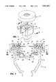
- FIG. 1is a perspective view of an auxiliary gas-tight seal according to the invention aligned with the rear housing of a trocar tube, prior to attaching the auxiliary gas-tight seal to the rear housing.
- FIG. 3Ais an exploded perspective view of an auxiliary gas-tight seal according to the invention showing its three main components.
- FIG. 3Bis an exploded cross-sectional view of auxiliary gas-tight seal according to the invention.
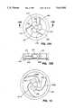
- FIG. 3Cis a perspective view of the laterally-compliant seal of the auxiliary gas-tight seal according to the invention showing how laterally displacing an instrument inserted into the instrument port laterally displaces the instrument seal and the stabilizing ring.
- FIG. 3Dis a cross-sectional view of part of an alternative embodiment of the cap and the base of an auxiliary gas-tight seal according to the invention.
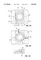
- FIG. 4Ais a cross-sectional view of the lower part of the base of the auxiliary gas-tight seal according to the invention and the rear housing of a trocar tube prior to engaging the lugs on the base with grooves in the rear housing.
- FIG. 4Bis a cross-sectional view of the lower part of the base of the auxiliary gas-tight seal according to the invention and the rear housing of a trocar tube prior to engaging the lugs on the base with grooves in the rear housing.
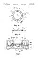
- FIG. 5Ais a cross-sectional view of the preferred embodiment of an auxiliary gas-tight seal with a conical instrument seal according to the invention.
- FIG. 5Bis an exploded cross-sectional view of the preferred embodiment of an auxiliary gas-tight seal with a conical instrument seal according to the invention.
- FIG. 5Cis a plan view of one of the stabilizing ring halves used in the preferred embodiment of an auxiliary gas-tight seal according to the invention.
- FIG. 5Dis a cross-sectional view of one of the stabilizing ring halves used in the preferred embodiment of an auxiliary gas-fight seal according to the invention.
- FIG. 6Ais a cross-sectional view of the seal molding of an auxiliary gas-tight seal with a bimaterial conical instrument seal according to the invention.
- FIG. 6Bis a cross-sectional view of the seal molding of an auxiliary gas-tight seal with a first type of tapered conical instrument seal according to the invention.
- FIG. 6Cis a cross-sectional view of the seal molding of an auxiliary gas-tight seal with a second type of tapered conical instrument seal according to the invention.
- FIG. 6Dis a cross-sectional view of the seal molding of an auxiliary gas-tight seal with a tapered flat instrument seal according to the invention.
- FIG. 6Eis a cross-sectional view of the seal molding of an auxiliary gas-tight seal with a flat instrument seal with a recessed area around the instrument port according to the invention.
- FIG. 7is a cross-sectional view of an auxiliary gas-tight seal with a conical instrument seal and a proximally-extending compliant mounting according to the invention.
- FIG. 8is a cross-sectional view of a first alternative embodiment of an auxiliary gas-tight seal according to the invention.
- FIG. 9is a cross-sectional view of a second alternative embodiment of an auxiliary gas-tight seal according to the invention.
- FIG. 10is a cross-sectional view of a third alternative embodiment of an auxiliary gas-tight seal according to the invention.
- FIG. 11Bis a cross-sectional view of the stabilizing ring and instrument seal of the auxiliary gas-tight seal according to the invention including the first embodiment of the lateral force transmitting mechanism according to the invention.
- FIG. 11Cis a plan view of the stabilizing ting and instrument seal of the auxiliary gas-tight seal according to the invention including the first embodiment of the lateral force transmitting mechanism according to the invention with a larger-diameter instrument inserted.
- FIG. 12Ais a plan view of the stabilizing ring and instrument seal of an auxiliary gas-tight seal according to the invention including a second embodiment of the lateral force transmitting mechanism according to the invention.
- FIG. 12Bis a cross-sectional view of the stabilizing ring and instrument seal of the auxiliary gas-tight seal according to the invention including the second embodiment of the lateral force transmitting mechanism according to the invention.
- FIG. 13is a plan view of the stabilizing ring and instrument seal of an auxiliary gas-tight seal according to the invention including a third embodiment of the lateral force transmitting mechanism according to the invention.
- FIG. 14Ais a plan view of the stabilizing ring and instrument seal of an auxiliary gas-tight seal according to the invention including a fourth embodiment of the lateral force transmitting mechanism according to the invention.
- FIG. 14Bis a plan view of the stabilizing ring and instrument seal of the auxiliary gas-tight seal according to the invention including the fourth embodiment of the lateral force transmitting mechanism according to the invention with a larger-diameter instrument inserted into the instrument port.
- FIG. 15Ais a plan view of an auxiliary gas-tight seal according to the invention including a fifth embodiment of a lateral force transmitting mechanism according to the invention.
- FIG. 15Bis a cross-sectional view of the auxiliary gas-tight seal according to the invention including the fifth embodiment of the lateral force transmitting mechanism according to the invention.
- the conventional gas-tight trocar tube sealuses the same piece of elastic material to form the gas-tight seal with the instrument, and to accommodate lateral displacement of the instrument.
- the need to accommodate lateral displacement of the instrumentrequires that, to prevent the seal from leaking, the radial force between the elastic material and the instrument be increased for an instrument at the minimum of the range of diameters. This reduces the maximum of the range of diameters above which there is excessive friction between the elastic material and the instrument.
- the preferred embodiment of the gas-tight seal according to the inventionwill next be described.
- the preferred embodimentis an auxiliary gas-tight seal that is intended to be attached to the rear housing of a trocar tube after the trocar assembly has been used to puncture the body wall, and the trocar has been withdrawn from the trocar tube.
- the preferred embodimentis an auxiliary gas-tight seal because the self-shielding mechanism of the trocar of the trocar assembly sold by the applicant's assignee operates by snapping the trocar distally into the cannula after the trocar tip has penetrated the body wall. In this trocar assembly, the trocar passes through a large-diameter, conventional gas-tight seal. If the gas-tight seal according to the invention were substituted for the conventional large-diameter gas-tight seal, friction between the gas-tight seal according to the invention and the trocar would be sufficiently high to impede the operation of the self-shielding mechanism.
- Friction in the gas-tight seal according to the inventionis higher than in the large-diameter conventional gas-tight seal because the considerably smaller diameter instrument port in the gas-tight seal according to the invention. Nevertheless, friction in the gas-tight seal according to the invention is significantly reduced compared with a conventional gas-tight seal having the same diameter instrument port.
- the gas-tight seal according to the inventionis not limited to use as an auxiliary gas-tight seal, however.
- a seal according to the inventioncould be built into, and form the main gas-tight seal in, a trocar tube for use in a trocar assembly in which the self-shielding mechanism does not move the trocar rapidly through the seal.
- a trocaris shown, for example, in U.S. Pat. No. 4,601,710.
- FIG. 1shows a perspective view of the auxiliary gas-tight seal 10 according to the invention aligned with the rear housing 12 of the trocar tube 14, just prior to attaching the auxiliary gas-tight seal to the rear housing.
- the rear face 16 of the rear housing 12includes the main gas-tight seal 18 in its center.
- On opposite sides of rear faceare the side walls 20 in which are formed the grooves 22.
- the rear housingincludes the side walls 20 and the grooves 22 as part of the mounting for the two door-type auxiliary gas-tight seals (not shown) formerly fitted to the rear housing, as described above.
- the auxiliary gas-tight seal 10includes lugs that engage in the grooves 22 to retain the auxiliary trocar seal in position on the rear face 16 of the rear housing 12. This way of attaching the auxiliary gas-tight seal 10 allows the auxiliary gas-tight seal 10 to replace the conventional door-type auxiliary gas-tight seals formerly fitted without the need to change the tooling used to mold the rear housing 12.
- the auxiliary gas-tight seal 10includes three main components: the seal body 30 which attaches to the rear housing 12, the instrument seal 32, and the seal mounting 34 for the instrument seal 32.
- the instrument sealis a piece of a elastic material in which the instrument port 38 is formed, preferably in its center.
- the instrument seal 32forms the gas-tight seal with an instrument passed through the instrument port 38.
- the instrument seal 32is mounted in the seal mounting 34 to form the laterally-compliant seal 40.
- the seal mounting 34is laterally compliant to allow the instrument seal 32 to move laterally in response to lateral movement of the instrument passed through the instrument port 38.
- the seal mounting 34is preferably also axially stiff, to hold the instrument seal 32 in position axially when an instrument is inserted into or withdrawn from the instrument port.
- the seal mounting 34includes the anchoring ting 42 and the stabilizing ting 44.
- the stabilizing ringincludes the stabilizing ring halves 44A and 44B, and the locking pins 46.
- the preferred embodimentincludes the seal molding 48, a part of which provides the instrument seal 32, and the rest of which provides pan of the seal mounting 34.
- the seal molding 48includes four distinct, radially separated zones, the instrument seal 32, the stabilizing ting anchor 50, the corrugated zone 52, and the anchoring ring 42.
- the seal molding 48is made of an elastic material, preferably silicone rubber, but it can alternatively be molded from other suitable elastic materials, such as latex.
- the instrument seal 32 and the seal mounting 34could alternatively be separate components joined at the stabilizing ring 44.
- This alternative constructionis more complex, but enables different materials to be used for the instrument seal 32 and the seal mounting 34.
- the seal mounting 34could be made from an inelastic material, such as MylarTM film.
- the part of the seal molding 48 providing the instrument seal 32forms a gas-tight seal with an instrument (not shown) passed through the instrument port 38 in the center of the seal molding.
- the part forming the instrument seal 32is relatively thick, about 1 mm (0.04") in the preferred embodiment. This enables this part of the seal molding to exert sufficient radial force against the instrument to form a gas-tight seal, even with an instrument at the minimum of the range of diameters.
- the part of the seal molding forming the instrument seal 32is also relatively thick to prevent it from being tom when a hook-shaped instrument is withdrawn from the instrument port.
- the present embodimentaccommodates instruments having a range of diameters, i.e., the instrument seal 32 forms a gas-tight seal with an instrument of a minimum diameter, and provides an acceptably low level of friction with an instrument as large as the maximum diameter.
- the minimum instrument diameter that can be accommodateddepends on the diameter of the instrument port 38.
- the instrument port 38is 3 mm (0.12") in diameter. With an instrument port of this diameter, the instrument seal 32 forms a gas-tight seal with an instrument as small as 4 mm (0.16”) in diameter.
- the preferred embodimentcan be adapted to accommodate different ranges of instrument diameters by changing the diameter of the instrument port 38. For example, a 2.2 mm (0.09”) diameter instrument port will provide a gas-tight seal with a 3 mm (0.12") diameter instrument.
- the instrumentWhen a larger-diameter instrument is inserted through the instrument port 38, the instrument stretches the elastomeric material of the seal molding 48 forming the instrument seal 32. This causes the part of the seal molding providing the instrument seal 32 to exert a radial force against the instrument, which results in friction between the instrument seal 32 and the instrument.
- the seal molding 48is preferably coated with a dry lubricant. Reducing friction increases the maximum of the range of instrument diameters that the auxiliary gas-tight seal 10 can accommodate without excessive friction between the instrument and the instrument seal.
- the preferred dry lubricantis poly-p-xylxylene, a crystalline organic solid, a thin film of which is low vacuum deposited from the vapor phase onto the seal molding 48.
- Poly-p-xylxyleneis sold under the brand name Parylene C by Union Carbide.
- An alternative dry lubricantis titanium, vapor deposited onto the surface of the seal molding 48.
- Other dry lubricants, sold by Spire Corporation, Bedford, Mass.,include: SPI-ARGENTTM and SPI-ARGENT IITM, which are ion beam deposited silver-based coatings; SPI-MetTM, and SPI-SiliconeTM.
- the seal mounting 34 for the instrument seal 32comprises the stabilizing ting 44; and the stabilizing ring anchor 50, the corrugated zone 52, and the anchoring ting 42, all of which form part of the seal molding 48.
- the part of the seal molding 48 forming the anchoring ring 42is considerably thicker than the part of the seal molding forming the instrument seal 32.
- the anchoring ting 42is relatively rigid, and serves to locate the laterally-compliant seal 40 in the seal body 30.
- the anchoring ringis located in an annular groove formed by the inner annular step 58 in the base 60 and the annular step 64 in the cap 66.
- the face 54 and the face 56 of the anchoring ringcontact the inner annular step 58 in the base 60, and the face 62 of the anchoring ring contacts the annular step 64 in the cap 66.
- the anchoring ringis slightly compressed between the annular step 64 and the inner annular step 58. This forms a gas-tight seal between the anchoring ring and the seal body.
- the part of the seal molding 48 forming the stabilizing ting anchor 50is located between the instrument seal 32 and the corrugated zone 52.
- the stabilizing ring anchor 50is an annular region in which the thickness of the seal molding 48 is increased on both sides.
- the stabilizing ring anchorserves to locate the seal molding 48 laterally with respect to the stabilizing ring 44.
- the corrugated zone 52interconnects the stabilizing ring anchor 50 and the anchoring ring 42.
- the part of the seal molding 48 forming the corrugated zone 52is between one tenth and one half of the thickness of the part of the seal molding forming the instrument seal 32.
- the part of the seal molding forming the corrugated zoneis about 0.2 mm (0.008") thick, and is also corrugated, as shown.
- the thinness of the corrugated zone 52 and its corrugated structureprovide lateral compliance between the inner periphery (i.e., the stabilizing ring 44) and the outer periphery (i.e., the anchoring ring 42) of the corrugated zone.
- the amount of radial force that must be applied to the stabilizing ring to displace laterally the stabilizing ring and the part of the corrugated zone to which it is attachedis relatively small.
- the lateral force that an instrument passed through the instrument port 38 must apply to the instrument seal 32 to displace laterally the instrument seal 32, the stabilizing ting 44, and the part of the corrugated zone to which the stabilizing ring is attachedis relatively small. Consequently, the additional radial force that the instrument seal 32 must apply to an instrument having a diameter at the minimum of the range of diameters to maintain the gas-tight seal with the instrument as the instrument is displaced laterally is also relatively small.
- Reducing the additional radial forcereduces the radial force that the instrument seal 32 exerts when a larger-diameter instrument is inserted into the instrument port 38. This, in turn, reduces friction between the seal and the instrument and increases the range of instrument diameters that the seal can accommodate.
- the stabilizing ting 44interconnects the instrument seal 32 and the corrugated zone 52, and transmits any radial force applied to the instrument seal 32 uniformly to the corrugated zone 52.
- the stabilizing ring 44also preferably transmits axial forces resulting from inserting and withdrawing an instrument into and from the instrument port 38 directly to the seal body 30, i.e., to the base 60 when an instrument is inserted, and to the cap 66 when an instrument is withdrawn.
- the stabilizing ringby isolating axial forces from the corrugated zone 52, and by transmitting radial forces uniformly to the corrugated zone, enables the strength of the corrugated zone to be minimized, and the lateral compliance of the corrugated zone to be maximized.
- the stabilizing ring 44comprises the stabilizing ring halves 44A and 44B, and the pins 46.
- the stabilizing ring halvesare annulus-shaped moldings of a suitable low-friction plastic, such as ABS, polycarbonate, or PTFE.
- Each stabilizing ring halfincludes in one face the annular groove 68 that mates with the stabilizing ring anchor 50 in the seal molding 48.
- the stabilizing ring halves 44A and 44Bare held in place on opposite sides of the seal molding 48 by the plural pins 46 inserted through one of the stabilizing ring halves (e.g., the stabilizing ring half 44A), the stabilizing ring anchor 50, and the other of the stabilizing ring halves (e.g., the stabilizing ring half 44B).
- the pins 46pass through the stabilizing ring anchor 50, where the material of the seal molding 48 is thicker, and forms a gas-tight seal with each pin 30. This prevents the pins 46 from providing a gas leakage path.
- the elastic material surrounding the instrument portis rigidly mounted at its periphery.
- the elastic material surrounding the instrument portstretches to accommodate lateral displacement of the instrument. Sufficient excess radial force must be provided between the elastic material and the instrument to keep the elastic material remote from the direction of the lateral displacement in contact with the instrument and therefore preserve the gas-tight seal.
- the elastic material surrounding the instrument port 38is also rigidly mounted at its periphery, but the rigidly-mounted elastic material is, in turn, compliantly mounted.
- the seal mounting 34allows the whole of the instrument seal 32 to move laterally. This is illustrated in FIG. 3C, in which the center line 41 of the instrument (not shown) is displaced laterally to the point indicated by the line 43.
- the lateral movement of the instrument sealis accommodated by the corrugated zone 52, the thin, corrugated material of which makes it laterally compliant.
- the laterally-compliant seal 40requires that considerably less excess radial force be provided between the instrument seal and the instrument to maintain contact with instrument when the instrument is laterally displaced. This, in turn, reduces the amount of friction between the instrument seal and the instrument when a larger-diameter instrument is inserted into the instrument port, and allows the seal to accommodate a larger range of instrument diameters.
- the seal body 30includes the base 60 and the cap 66, as shown in FIG. 3A.
- the base 60is a molding of a suitable plastic, such as ABS, or polycarbonate.
- the baseincludes the internal face 70 over which the stabilizing ring 44 of the seal mounting 34 can slide laterally.
- the basealso includes the inner annular step 58 and the outer annular step 80.
- the inner annular step 58together with the annular step 64 in the cap, locates the anchoring ring 42 of the seal molding 48, as described above.
- the outer annular step 80abuts the edge 81 of the cap 60, which defines the axial location of the cap 66 relative to the base 60.
- Thisdefines the amount of compression applied to the anchoring ring 42 when the cap and the base are mated to form the seal body 30. This also defines the clearance between the internal face 70 of the base 60 and the internal face 78 of the cap 66, and hence the clearance between the stabilizing ring 44 and the internal faces 70 and 78.
- the basealso includes the bore 72, which has a diameter of slightly greater than the diameter as the largest-diameter instrument that can be accommodated by the main gas-tight seal in the trocar tube, plus twice the thickness of the instrument seal 32.
- Surrounding the bore 72are the lugs 74 and the plane sealing surface 76 with which the auxiliary gas-tight seal 10 is attached to the rear face 16 of the rear housing 12 (FIG. 1).
- the lugs 74are preferably tapered.
- the lugs 74 and the plane sealing surface 76are specific to the preferred way of attaching the auxiliary gas-tight seal 10 to the rear housing of the trocar tube sold by the applicant's assignee.
- the auxiliary gas-tight seal 10could be attached to the rear housing of the trocar tube made by the applicant's assignee in other ways, which would require a different arrangement of the base 60 and/or the cap 66.
- the auxiliary gas-tight seal 10could be adapted for attaching to the rear housings of trocar tubes made by others, which might also require a different arrangement of the base 60 and/or the cap 66.
- a gas-tight seal similar to the auxiliary gas-tight seal 10can be built into the rear housing of a trocar tube, in which case, the base 60 would be formed as pan of the rear housing molding.
- the cap 66is also a molding of a suitable plastic such as ABS or polycarbonate.
- the capfits over the base 60, and includes the internal face 78, with respect to which the stabilizing ring 44 of the seal mounting 34 can slide laterally.
- the cap 66also includes the inner annular step 64 and the edge 81.
- the annular step 64clamps the anchoring ring 42 of the seal molding 48 into the annular step 58 in the base 60, as described above.
- the edge 81defines the relative axial location of the base and the cap, as described above.
- the cap 66also includes the central bore 82, which also has a diameter of slightly greater than the diameter as the largest-diameter instrument that can be accommodated by the main gas-tight seal in the trocar tube, plus twice the thickness of the instrument seal 32.
- the cap 66is attached to the base 60 by a suitable snap arrangement, a suitable adhesive, by ultrasonic welding, or by some other suitable method.
- the capmay be adapted for attaching the auxiliary gas-tight seal 10 to the rear housing of the trocar tube in addition to, or as an alternative to, the attachment arrangements on the base 60 already described.
- the cap 66Amay be formed with two annular steps, and the base 60A may be formed with a single annular step, as shown in FIG. 3D.
- the cap 66Ais formed with an inner annular step 64A and an outer annular step 80A, and the base is formed with the wide annular step 58A.
- the annular groove formed between the inner annular step 64A in the cap 66A and the inner part of the wide annular step 58A in the baselocates and seals with the anchoring ring 42.
- the outer part of the wide annular step 58A in the base 60A abutting the outer annular step 80A in the cap 66Adefines the relative axial location of the base and the cap.
- the surgeonthen rotates the auxiliary gas-tight seal in a clockwise direction, looking from the top, to engage the lugs 74 into the grooves 22.
- the lugs 74are tapered, as shown in FIG. 4C, such that, as the auxiliary gas-tight seal is rotated, the tapered lugs engaging with the grooves 22 moves the plane sealing face 76 into engagement with the outer sealing lip 92 (see FIG. 2).
- the surgeonstops rotating the auxiliary gas-tight seal when the stop 96 on each lug is fully engaged with the corresponding stop 98 in the grooves 22. Juxtaposing the stop 96 with the stop 98 and the lugs 74 with the grooves 22 positively locates the auxiliary gas-tight seal 10 in all three dimensions relative to the rear housing 12.
- auxiliary gas-tight seal 10The shape of the auxiliary gas-tight seal 10 and the simple attachment mechanism makes it easy to attach the auxiliary gas-tight seal to, and to remove the auxiliary gas-tight seal from, the rear housing 12 of the trocar tube 14, even with gloved hands.
- the preferred embodiment of the auxiliary gas-tight sealcan accommodate instruments having a 3:1 range of diameters, for example, from 4 mm to 12 mm, the auxiliary gas-tight seal will be fitted to the trocar tube immediately after the trocar has been removed from the trocar tube, and will remain attached to the trocar tube throughout the rest of the procedure.
- the seal molding 40Bretains the four zones, namely, the instrument seal 32B, the stabilizing ting anchor 50B, the corrugated zone 52B, and the anchoring ring 42B, described above. 0f these, the stabilizing ring anchor and the anchoring ting are unchanged, and so will not be further described.
- the preferred material of the seal molding 48Bis silicone rubber. Silicone rubber has excellent rebound, i.e., ability to recover after deformation, but a less good ability to resist penetration. Polyurethane is an alternative material for the seal molding: the penetration resistance of polyurethane is superior to that of silicone rubber, but its rebound is inferior.
- the corrugated zone 52 shown in FIGS. 1 through 4Cuses a folded arrangement accommodated within the overall height of the stabilizing ring 44.
- the lateral compliance of the corrugated zone 52Bhas been increased by forming the corrugated zone from a series of substantially vertical elements 51, 53, 55, interconnected by substantially semicircular sections 57, 59, 61. Compliance is further increased by making the vertical elements 51, 53, 55 substantially longer than the sloped elements of the corrugated zone 52 shown in FIG. 3A.
- the material of the corrugated zone 52Bbends and/or buckles to accommodate the lateral movement of the instrument seal 32B and stabilizing ring 44B. This requires considerably less force than stretching the material of the corrugated zone.
- the preferred thickness of the corrugated zone 52Bis little changed from that of the corrugated zone 52 shown in FIG. 3A.
- the diameter of the bore 72B shown in FIGS. 5A and 5Bis increased. This is necessary because the bore must accommodate not only the instrument, it must also accommodate the instrument seal 32B, and the maximum lateral excursion of the instrument seal. To provide the necessary diameter of the bore, and to provide an adequate area on the plane sealing face 76B, the bore is tapered towards the plane sealing face 76B as shown.
- the cap 66Bis similar to the cap 60 shown in FIG. 3A, except that its height is increased to accommodate the increased height of the corrugated zone 58B and the cap 60B.
- the capis formed with two internal circumferential steps 64B and 80B.
- the anchoring ringis located in the annular groove formed between the outer face 58B of the outer wall 65 of the annular pocket 63, the annular part 67 of the base 60B outside the wall 65, and the circumferential step 64B in the cap.
- the annular groovelocates and forms a gas-tight seal with the anchoring ting 42B.
- the part 67 of the basefits into the circumferential step 80B and defines the relative axial location of the base and the cap. This, in turn, defines the compression of the anchoring ring 42B, and the distance between the faces 70B and 78B.
- the stabilizing ring 44Bis formed of two identical stabilizing ring halves 44AB and 44BB, as shown in FIGS. 5A and 5B.
- One of the stabilizing ring halves 44ABis shown in plan and in cross section in FIGS. 5C and 5D, respectively.
- Each stabilizing ring halfis an annular plastic ring half molding 71.
- Formed in one plane face of the moldingis the annular groove 73 that accommodates the stabilizing ring anchor 50B of the seal molding 48B.
- the pins 75In four equally-spaced locations in the annular groove are formed the pins 75, and in four equally-spaced locations, spaced equally between the pins 75, are formed the pin holes 77.
- Eight equally-spaced pin holes 79are also formed in the stabilizing ring anchor in the seal molding 48B.
- the two stabilizing ring halves 44AB and 44BBare attached to the seal molding 48B simply by inverting, and rotating through 45 degrees, one ring half molding 71 relative to the other.
- the ring half pins 75are then inserted through the pin holes 79 in the seal molding, and are pressed into the pin holes 77 in the other ring half, where they are retained by friction.
- the thickness of instrument seal 32D and 32Emay be radially varied to provide a better relationship between penetration resistance and friction between the instrument seal and the instrument.
- FIG. 6Bshows the thickness of the instrument seal 32D decreasing with distance from the center of the instrument port 38D.
- FIG. 6Cshows the thickness of the instrument seal 32E increasing with distance from the center of the instrument port 38E.
- the thickness of the instrument sealmay be radially varied in steps to facilitate stretching of the instrument seal and to reduce friction between the instrument seal and the instrument.
- the instrument-contacting surface of the instrumentmay be formed with flutes extending from the instrument port to the stabilizing ring anchor, or with a textured, marbled, or matt finish.
- scales, or cut-resistant elementssuch as overlapping polyurethane scales, may be mechanically attached to, bonded to, or formed in the instrument-contacting surface of the instrument seal to increase the penetration resistance of the surface and to reduce friction between the instrument seal and the instrument.
- the basic conical shape of the instrument seal 32B and its thicknesscould be varied to provide an optimum relationship between penetration resistance and friction between the instrument seal and the instrument.
- the shape of the instrument sealwould be more complex than the simple conical shape shown, for example, in FIGS. 5A and 5B.
- the radial variation of thicknesswould be more complex than the simple linear taper shown in FIGS. 6B and 6C.
- FIG. 7shows an alternative embodiment in which the corrugated section 52C of the seal molding 48C extends proximally instead of distally.
- the seal moldingalso includes the conical instrument seal 32C.
- the base 60C and the cap 66Care changed.
- the base 60Cretains the large internal face 70C of the arrangement shown in FIG. 3A.
- the plane face 70Cterminates in the peripheral wall 65C.
- the bore 72Chas a large diameter to accommodate the instrument, the conical instrument seal, and the lateral movement of the instrument seal.
- the cap 66Chas the internal face 78C that occupies a small part of the area of the cap, and is surrounded by the annular pocket 83 that accommodates the corrugated zone 52C.
- the bore 82Cis flared towards the plane face 78C.
- the tunnel between the proximal face 85 of the cap and the instrument port 38C at the distal end of the instrument sealguide the instrument towards the center of the instrument port and facilitate passage of the instrument through the instrument port.
- FIGS. 5A through 7may also be selectively included in the embodiment shown in FIGS. 1 through 4C.
- the seal mounting 134includes the stabilizing ring 144, the stabilizing ring anchor 150, and the corrugated seal 121.
- the stabilizing ring 144includes the stabilizing ring halves 123 and 125, which mate with the stabilizing ring anchor 150.
- the stabilizing ring half 123is similar to the stabilizing ring halves 44A and 44B shown in FIGS. 3A and 3B, but its outer curved face 127 is changed because there is no seal molding to pass through it.
- the stabilizing ring half 125is substantially changed relative to the stabilizing ring half 44B.
- the plane face 129 of the stabilizing ring half 125is extended radially inwards toward the instrument port 138, and then is extended axially away from the instrument seal 132 to form the lip 131.
- the lip 131defines the periphery of a bore 133 which has a diameter about 50% greater than the diameter of the bore 164 in the cap 166.
- the corrugated seal 121is a molding of an elastic material, for example, silicone rubber.
- the corrugated sealincludes an inner anchoring ring 137 and an outer anchoring ring 139 interconnected by a corrugated section 141.
- the anchoring ringsare preferably thicker than the corrugated section.
- the inner anchoring ring 137is adapted for attaching to the lip 133 by means of a suitable adhesive, a metal or plastic clamp (not shown), or some other suitable means.
- the outer anchoring ring 139is adapted for attaching to the base 160 by means of a suitable adhesive, a metal or plastic clamp (not shown), or some other suitable means.
- the outer anchoring ringcan be compressed in an annular groove (not shown) formed between a step on the base 160 and a corresponding step on a suitable annular sleeve (not shown) fitting inside the base similar to the way in which the base fits inside the cap in FIGS. 3A and 3B.
- FIG. 8operates similarly to the preferred embodiment described with reference to FIGS. 3A and 3B.
- the instrument seal 132is free to move laterally between the cap 166 and the base 160. This allows the excess radial force between the instrument seal 132 and the instrument to be reduced, which, in turn, reduces friction between the instrument seal 132 and an instrument having a diameter at the maximum of the range of diameters.
- the sealcan accommodate a greater range of instrument diameters without leaking and without excessive friction.
- the stabilizing ring 144isolates the instrument seal 132 from the seal mounting 134, as before, and also transfers axial forces directly from the instrument seal 132 to the seal body 130, comprising the cap 166 and the base 160.
- the seal mounting 134is laterally compliant while providing a gas-fight seal between the seal body 130 and the instrument seal 132. To move the instrument seal 132 laterally requires that the instrument exert relatively little radial force on the instrument port 138.
- a conical instrument sealsimilar to that shown in FIG. 5A, may be substituted for the flat instrument seal 132.
- FIG. 9shown in FIG. 9, the corrugated seal 141 shown in FIG. 8, and the planar corrugated seal 52 shown in FIGS. 3A and 3B are dispensed with, and the laterally-compliant seal is provided by a sliding seal between the stabilizing ring and the seal body.
- FIG. 9parts that are similar to the embodiments shown in FIGS. 3A and 3B, and FIG. 8 are numbered with the same reference numbers with 100 or 200, respectively, added.
- the base 260 and the cap 266are similar to the base 60 and the cap 66 shown in FIGS. 3A and 3B, except that no provision is made for mounting the anchoring ring 42 (FIGS. 3A and 3B).
- the instrument seal 232is similar to the instrument seal 132 shown in FIG. 8. As in FIG. 8, the instrument seal 232 is molded with the stabilizing ring anchor 250 at its periphery.
- the wiper 255contacts internal face 278 of the cap 266.
- the wiper 257contacts the internal face 270 of the base 260.
- Contact between the wiper 257 and the internal face 270forms a primary sliding gas-tight seal.
- Contact between the upper wiper 255 and the internal face 278forms a secondary gas-tight seal that seals any gas that escapes past the primary sliding gas-tight seal.
- the axially-opposed primary and secondary gas-tight sealsrequire a relatively small axial force between the wipers and their respective internal faces to provide an effective gas-tight seal.
- This sealremains gas-tight when an axial load is imposed on the seal, such as that imposed when an instrument is inserted or withdrawn, despite the small force between the wipers and their respective sealing faces. It is desirable to have a relatively small force between the wipers and their respective sealing surfaces to minimize friction, and thus maximize the lateral compliance of the instrument seal 232. Friction can be further reduced by coating the wipers 255 and 257 and the internal faces 270 and 278 with a suitable anti-friction layer.
- a conical instrument sealsimilar to that shown in FIG. 5A, may be substituted for the flat instrument seal 232.
- FIG. 10shows a simplified version of the arrangement shown in FIG. 9 in which the wipers are omitted from the stabilizing ting 344. Parts similar to parts shown in FIG. 9 are numbered with the same reference numbers with 100 added.
- the internal faces 370 and 378, the mating surfaces of the cap 366 and the base 360, and the plane surfaces of the stabilizing ting 344are formed with sufficient precision that the gap between the plane faces of the stabilizing ring and the respective internal faces of the cap and the base is of the order of 25 ⁇ m (0.001"). This dimension is large enough to allow the stabilizing ting to slide freely between the cap and the base.
- a conical instrument sealsimilar to that shown in FIG. 5A, may be substituted for the flat instrument seal 332.
- the radial force between the instrument seal 32 (FIG. 3A) and the instrumentcan be further reduced by transmitting directly from the instrument to the stabilizing ring the lateral force required to move the seal mounting 34 laterally. This relieves the instrument seal of the task of transmitting this lateral force, which enables the radial force between the instrument seal and a minimum-diameter instrument to be further reduced. Reducing the radial force between the instrument seal and a minimum-diameter instrument increases the range of instrument diameters that the seal can accommodate.
- FIGS. 11A-11C, 12A, 12B, 13, 14A and 14Bonly show the stabilizing ring 444 and the instrument seal 432.
- the lateral force transmitting mechanism embodiments shown in these Figures and in FIGS. 15A and 15Bmay be applied to any of the embodiments and variations shown in FIGS. 3A and 3B, 5A, 5B, 6A through 6E, 7, 8, 9, and 10, all of which include a stabilizing ring and an instrument seal.
- the thickness of one of the stabilizing ring halves comprising the stabilizing ring 444is increased to accommodate the lateral force transmitting mechanism.
- the increase in the thickness of the stabilizing ring half 423is relatively small because the simple lateral force transmitting mechanism has a relatively low profile.
- the more complex lateral force transmitting mechanisms shown in FIGS. 12A and 12B, 13, and 14A and 14Brequire a greater increase in the thickness of the stabilizing ting half 423.
- FIGS. 11A through 11CIn the simple lateral force transmitting mechanism shown in FIGS. 11A through 11C, three wire springs 469, 471, and 473 are attached in a radially-symmetrical arrangement to the stabilizing ting half 423.
- the wire springsare radially offset so that they are substantially tangential to the instrument port 438.
- the parts of the wire springs adjacent to the instrument port 438may overlap one another as shown. This may be achieved by appropriately bending each wire spring, or by mounting each wire spring at a different point in the thickness of the stabilizing ting, as shown in FIG. 11B.
- the wire springs 469, 471, and 473are biased into contact the instrument, such as the instrument I, inserted into the instrument port 438.
- the wire springsexert a radial compressive force against the instrument.
- the compressive forceis as radially symmetrical as is possible with a radial force applied by three discrete elements.
- the compressive forcecan be made more symmetrical at the expense of greater complexity by increasing the number of wire springs.
- the instrumentWhen the instrument I is moved laterally, the instrument applies a lateral force to one or more of the wire springs 469, 471, and 473. Each wire spring to which the lateral force is applied transmits the lateral force directly to the stabilizing ring 444. The lateral force thus applied directly to the stabilizing ring moves the stabilizing ting and the instrument seal 432 laterally with the lateral movement of the instrument. In this way, the lateral force transmitting mechanism moves the instrument seal laterally and considerably reduces the force between the instrument seal and the instrument required to move the instrument seal laterally.
- the elasticity of the wire springs 469, 471, and 473enables the wire springs to move radially when a larger-diameter instrument, such as the instrument I' shown in FIG. 11C, is inserted into the instrument port.
- the wire springs 469,471, and 473exert a radial force against the instrument. This radial force increases with increasing diameter of the instrument. However, friction on the instrument resulting from the radial force exerted by the wire springs is less than that resulting from the radial force exerted by the instrument seal because the coefficient of friction between the wire springs and the instrument is less than that between the instrument seal and the instrument.
- the parts of the wire springs 469,471, and 473 remote from the stabilizing ring 444may be fitted with suitably-shaped paddles to make inserting the instrument easier. Inserting the instrument may be made even easier by fitting each wire spring with a roller, as shown in FIGS. 12A and 12B.
- Each of the wire springs 469, 471, and 473is fitted with a roller 475, 477, and 479, respectively.
- Each rolleris free to rotate on its respective wire spring, and is axially located on the wire spring by bushes, or some other suitable device.
- the bushes 481 and 483are shown retaining the roller 477 on the wire spring 471, for example.
- the radial force applied to the instrument by the lateral force transmitting mechanismcan be made less dependent on the instrument diameter increases by making the wire springs longer, as shown in FIG. 13.
- the wire springs 469A, 471A, and 473Aare curved, which enables their length to be increased within the confines of the stabilizing ring 444.
- the rollers 475,477, and 479can be omitted, or can be replaced by paddles, if desired.
- the rollers 475, 477, and 479are mounted on the axles 485,487, and 490, respectively.
- the axles 485,487, and 489swivel on the pins 49 1,493, and 495 mounted on the stabilizing ting 444.
- a hairspring arrangement 495biases each pivoted axle towards the instrument port 438.
- Such an arrangementmakes the radial force applied to the instrument by the lateral force transmitting mechanism less dependent on the instrument diameter.
- the rollersare forced outwards, as shown in FIG. 14B, but the long effective length of the hairspring arrangement makes the radial force between the rollers and the instrument relatively independent of the diameter of the instrument.
- a conical instrument sealsimilar to that shown in FIG. 5A, may be substituted for the flat instrument seal 432.
- FIGS. 15A and 15Bshow an arrangement of spring-loaded bumpers.
- Each of the four bumpers 511, 513, 5 15, and 517is mounted on a compression spring 519, 521,523, and 525 inside the stabilizing ring 544.
- This arrangementexerts a radial compressive force against an instrument inserted into the instrument port 538.
- the bumpers and springstransmit a lateral force directly to the stabilizing ting 544. This moves the instrument seal 532 laterally, and considerably reduces the force between the instrument seal and the instrument required to move the instrument seal laterally.
- a conical instrument seal and a corrugated sectionmay be substituted for the flat instrument seal 532, and the corrugated section 552.
Landscapes
- Health & Medical Sciences (AREA)
- Heart & Thoracic Surgery (AREA)
- Life Sciences & Earth Sciences (AREA)
- Public Health (AREA)
- Biomedical Technology (AREA)
- Engineering & Computer Science (AREA)
- Animal Behavior & Ethology (AREA)
- General Health & Medical Sciences (AREA)
- Veterinary Medicine (AREA)
- Surgery (AREA)
- Hematology (AREA)
- Pulmonology (AREA)
- Anesthesiology (AREA)
- Pathology (AREA)
- Nuclear Medicine, Radiotherapy & Molecular Imaging (AREA)
- Medical Informatics (AREA)
- Molecular Biology (AREA)
- Surgical Instruments (AREA)
- Materials For Medical Uses (AREA)
- Sealing Material Composition (AREA)
- Dental Tools And Instruments Or Auxiliary Dental Instruments (AREA)
Abstract
Description
Claims (46)
Priority Applications (7)
| Application Number | Priority Date | Filing Date | Title |
|---|---|---|---|
| US08/040,373US5411483A (en) | 1993-02-10 | 1993-03-30 | Gas-tight seal accommodating surgical instruments with a wide range of diameters |
| PCT/US1994/001569WO1994017844A1 (en) | 1993-02-10 | 1994-02-09 | Seal accomodating diametrical range of surgical instruments |
| EP94910686AEP0746348B1 (en) | 1993-02-10 | 1994-02-09 | Seal accomodating diametrical range of surgical instruments |
| CA002155743ACA2155743C (en) | 1993-02-10 | 1994-02-09 | Seal accomodating diametrical range of surgical instruments |
| AU62981/94AAU685093B2 (en) | 1993-02-10 | 1994-02-09 | Seal accomodating diametrical range of surgical instruments |
| DE69431883TDE69431883T2 (en) | 1993-02-10 | 1994-02-09 | GASKET FOR ALL DIAMETER RANGES OF SURGICAL INSTRUMENTS |
| AT94910686TATE229353T1 (en) | 1993-02-10 | 1994-02-09 | SEAL FOR ALL DIAMETER RANGES OF SURGICAL INSTRUMENTS |
Applications Claiming Priority (2)
| Application Number | Priority Date | Filing Date | Title |
|---|---|---|---|
| US08/015,765US5407433A (en) | 1993-02-10 | 1993-02-10 | Gas-tight seal accommodating surgical instruments with a wide range of diameters |
| US08/040,373US5411483A (en) | 1993-02-10 | 1993-03-30 | Gas-tight seal accommodating surgical instruments with a wide range of diameters |
Related Parent Applications (1)
| Application Number | Title | Priority Date | Filing Date |
|---|---|---|---|
| US08/015,765Continuation-In-PartUS5407433A (en) | 1993-02-10 | 1993-02-10 | Gas-tight seal accommodating surgical instruments with a wide range of diameters |
Publications (1)
| Publication Number | Publication Date |
|---|---|
| US5411483Atrue US5411483A (en) | 1995-05-02 |
Family
ID=26687772
Family Applications (1)
| Application Number | Title | Priority Date | Filing Date |
|---|---|---|---|
| US08/040,373Expired - LifetimeUS5411483A (en) | 1993-02-10 | 1993-03-30 | Gas-tight seal accommodating surgical instruments with a wide range of diameters |
Country Status (7)
| Country | Link |
|---|---|
| US (1) | US5411483A (en) |
| EP (1) | EP0746348B1 (en) |
| AT (1) | ATE229353T1 (en) |
| AU (1) | AU685093B2 (en) |
| CA (1) | CA2155743C (en) |
| DE (1) | DE69431883T2 (en) |
| WO (1) | WO1994017844A1 (en) |
Cited By (162)
| Publication number | Priority date | Publication date | Assignee | Title |
|---|---|---|---|---|
| US5533967A (en)* | 1992-12-01 | 1996-07-09 | Cardiac Pathways Corporation | Steerable catheter with adjustable bend location and method |
| US5554123A (en)* | 1994-10-31 | 1996-09-10 | Glenn Herskowitz | Portable infusion pump |
| US5628732A (en)* | 1996-01-19 | 1997-05-13 | Ethicon Endo-Surgery, Inc. | Trocar with improved universal seal |
| EP0778039A1 (en) | 1995-12-07 | 1997-06-11 | Sarcos, Inc. | Catheter guide wire |
| US5657963A (en)* | 1993-06-16 | 1997-08-19 | United States Surgical Corporation | Seal assembly for accommodating introduction of surgical instruments |
| US5697913A (en)* | 1996-08-09 | 1997-12-16 | Ethicon Endo-Surgery, Inc. | Trocar including cannula with stepped region |
| US5730418A (en)* | 1996-09-30 | 1998-03-24 | The Kipp Group | Minimum fluid displacement medical connector |
| WO1998024359A1 (en)* | 1996-12-05 | 1998-06-11 | Helix Medical. Inc., | Sigmoid splint device for endoscopy |
| US5792113A (en)* | 1996-12-12 | 1998-08-11 | Ethicon Endo-Surgerym Inc. | Universal seal for a trocar |
| US5820600A (en)* | 1996-05-14 | 1998-10-13 | Innerdyne, Inc. | Adjustable introducer valve |
| US5820604A (en)* | 1996-06-11 | 1998-10-13 | Endolap, Inc. | Cannula cap including yeildable outer seal and flapper valve |
| US5827228A (en) | 1991-10-18 | 1998-10-27 | Ethicon, Inc. | Seal members for surgical trocars |
| US5827227A (en)* | 1996-07-17 | 1998-10-27 | Delago; Augustin J. | Catheter having a radially adjustable sheath |
| EP0890342A1 (en) | 1997-07-11 | 1999-01-13 | Gynecare, Inc. | Instrument for operations on the uterus |
| EP0917885A1 (en) | 1997-11-21 | 1999-05-26 | Sarcos, Inc. | Improved hybrid catheter guide wire apparatus and method |
| US5941852A (en)* | 1994-01-31 | 1999-08-24 | Imagyn Medical Technologies California, Inc. | Trocar assembly |
| US5954713A (en)* | 1996-07-12 | 1999-09-21 | Newman; Fredric A. | Endarterectomy surgical instruments and procedure |
| WO1999052577A1 (en)* | 1998-04-13 | 1999-10-21 | Applied Medical Resources Corporation | Cone-shaped universal seal having nonuniform surface and seal assembly including same |
| US6066117A (en)* | 1996-06-11 | 2000-05-23 | Endolap, Inc. | Cannula flapper valve assembly |
| USD426635S (en)* | 1998-08-18 | 2000-06-13 | Genicon, Lc | Combination trocar, cannula, and valve |
| US6083203A (en) | 1990-07-26 | 2000-07-04 | Yoon; Inbae | Endoscopic portal |
| US6123689A (en)* | 1996-06-11 | 2000-09-26 | Applied Medical Resources Corporation | Reusable cannula with disposable seal |
| USD443360S1 (en) | 2000-03-22 | 2001-06-05 | Dexterity Surgical Inc. | Distal end of obturator for a trocar |
| USD449887S1 (en) | 2000-01-26 | 2001-10-30 | Genicon Lc | Combined obturator, cannula and valve assembly |
| WO2001089397A1 (en) | 2000-05-24 | 2001-11-29 | Surgical Innovations Ltd | Surgical seal |
| US6482181B1 (en) | 1997-05-28 | 2002-11-19 | Tyco Healthcare Group Lp | Trocar seal system |
| US20030050604A1 (en)* | 1999-12-30 | 2003-03-13 | Lui Chun Kee | Splittable medical valve |
| US6551282B1 (en) | 1998-02-23 | 2003-04-22 | Tyco Healthcare Group Lp | Universal seal for use with endoscopic cannula |
| US6595946B1 (en) | 2000-02-25 | 2003-07-22 | United States Surgical Corporation | Valve assembly |
| US20030150775A1 (en)* | 2000-04-17 | 2003-08-14 | Stuntz Gordon F. | Cycle oil conversion process |
| US6702787B2 (en) | 1997-05-02 | 2004-03-09 | Tyco Healthcare Group Lp | Trocar seal system |
| US20040064100A1 (en)* | 2000-10-13 | 2004-04-01 | Smith Robert C. | Valve assembly including diameter reduction structure for trocar |
| US20040068232A1 (en)* | 2002-10-04 | 2004-04-08 | Hart Charles C. | Surgical access device with pendent valve |
| US20040066008A1 (en)* | 2002-10-04 | 2004-04-08 | Smith Robert C. | Introducer seal assembly |
| US20040106942A1 (en)* | 2002-12-02 | 2004-06-03 | Applied Medical Resources Corporation | Universal access seal |
| US6755825B2 (en) | 1998-09-23 | 2004-06-29 | Sherwood Services Ag | Electrosurgical device having a dielectric seal |
| US20040204682A1 (en)* | 2000-11-06 | 2004-10-14 | Smith Robert C. | Surgical sealing apparatus |
| US20050033342A1 (en)* | 2001-11-13 | 2005-02-10 | Hart Charles C | Multi-seal trocar system |
| US20050165433A1 (en)* | 2004-01-23 | 2005-07-28 | Haberland Gary W. | Trocar having planar fixed septum seal and related methods |
| US20050209607A1 (en)* | 2004-03-22 | 2005-09-22 | John Lipchitz | Medical cannula assembly |
| US20050261661A1 (en)* | 2002-04-26 | 2005-11-24 | Mcfarlane Richard H | Floating seal assembly for a trocar |
| US20050273378A1 (en)* | 2004-06-02 | 2005-12-08 | Overstock.Com, Inc. | System and methods for electronic commerce using personal and business networks |
| US20060004331A1 (en)* | 2000-07-11 | 2006-01-05 | Fangrow Thomas F Jr | Medical valve with positive flow characteristics |
| US20060020281A1 (en)* | 2000-10-13 | 2006-01-26 | Smith Robert C | Valve assembly including diameter reduction structure for trocar |
| US20060041232A1 (en)* | 2004-07-21 | 2006-02-23 | Stearns Ralph A | Introducer assembly with suspended seal |
| US20060047293A1 (en)* | 2004-01-23 | 2006-03-02 | Haberland Gary W | Trocar having planar fixed septum seal and related methods |
| US20060069623A1 (en)* | 2004-09-23 | 2006-03-30 | Overstock.Com, Inc. | System, program product, and methods for online image handling |
| US20060085251A1 (en)* | 2004-10-14 | 2006-04-20 | Overstock.Com, Inc. | System and method of presenting on-line product selection based on internal marketing and user popularity |
| US20060149305A1 (en)* | 2005-01-06 | 2006-07-06 | Brian Cuevas | Surgical seal for use in a surgical access apparatus |
| US20060212006A1 (en)* | 1996-12-16 | 2006-09-21 | Fangrow Thomas F Jr | Medical valve with positive flow characteristics |
| EP1707235A1 (en)* | 2005-03-31 | 2006-10-04 | Tyco Healthcare Group Lp | Surgical hand access apparatus |
| US20060276751A1 (en)* | 2004-01-23 | 2006-12-07 | Genico, Inc. | Trocar and cannula assembly having conical valve and related methods |
| US7153319B1 (en) | 2000-01-26 | 2006-12-26 | Genico, Inc. | Trocar system having shielded trocar |
| USD537941S1 (en) | 2004-03-09 | 2007-03-06 | Genico, Inc. | Combination medical clamp and medical coupler |
| US20070078726A1 (en)* | 2005-09-21 | 2007-04-05 | Macdonald Korth Holly C | System, program product, and methods for online image handling |
| US20070106522A1 (en)* | 2005-11-08 | 2007-05-10 | Bruce Collins | System for distributing packages and channels to a device |
| US7235062B2 (en) | 2002-01-24 | 2007-06-26 | Applied Medical Resources Corporation | Surgical access device with floating gel seal |
| US20080033363A1 (en)* | 2004-01-23 | 2008-02-07 | Haberland Gary W | Trocar and cannula assembly having conical valve and related methods |
| US20080051739A1 (en)* | 2006-08-25 | 2008-02-28 | Mcfarlane Richard H | Caged floating seal assembly |
| US20080161758A1 (en)* | 2006-11-14 | 2008-07-03 | Insignares Rogelio A | Trocar and cannula assembly having variable opening sealing gland and related methods |
| US20080249373A1 (en)* | 2004-04-05 | 2008-10-09 | Tyco Healthcare Group Lp | Surgical hand access apparatus |
| US20080294125A1 (en)* | 2007-05-22 | 2008-11-27 | Kenneth Allen Focht | Surgical access assembly with winepress seal |
| US20080290605A1 (en)* | 2007-05-22 | 2008-11-27 | Tyco Healthcare Group Lp | Access assembly with whisker seal |
| US20080300466A1 (en)* | 2007-05-30 | 2008-12-04 | Tyco Healthcare Group Lp | Self constricting orifice seal |
| US20090018174A1 (en)* | 2005-11-08 | 2009-01-15 | Pradip Kumar Bhatnagar | Macrolides as anti-inflammatory agents |
| US20090018508A1 (en)* | 2007-06-22 | 2009-01-15 | Medical Components, Inc. | Tearaway Sheath Assembly with Hemostasis Valve |
| US20090082720A1 (en)* | 2007-09-25 | 2009-03-26 | Tyco Healthcare Group Lp | Seal assembly for surgical access device |
| US20090143739A1 (en)* | 2007-09-18 | 2009-06-04 | Medical Components, Inc | Tearaway sheath assembly with split hemostasis valve |
| US20090183084A1 (en)* | 2007-12-31 | 2009-07-16 | Robertson Ian B | System and method for assigning computer users to test groups |
| US7563250B2 (en) | 2002-11-08 | 2009-07-21 | Tyco Healthcare Group | Self-sealing cannula |
| US20090234290A1 (en)* | 2008-03-14 | 2009-09-17 | Medical Components, Inc. | Tearaway Introducer Sheath with Hemostasis Valve |
| US20090326468A1 (en)* | 2008-06-27 | 2009-12-31 | Tyco Healthcare Group Lp | Pressurized surgical valve |
| US20100016800A1 (en)* | 2008-07-17 | 2010-01-21 | Brian Rockrohr | Piston seal for single incision surgery |
| US20100016797A1 (en)* | 2008-07-17 | 2010-01-21 | Tyco Healthcare Group Lp | Constricting mechanism for use with a surgical access assembly |
| US20100145152A1 (en)* | 2004-04-05 | 2010-06-10 | Tyco Healthcare Group Lp | Surgical hand access apparatus |
| US20100179479A1 (en)* | 2009-01-09 | 2010-07-15 | Applied Medical Resources Corporation, Inc. | Pleated trocar shield |
| US20100222747A1 (en)* | 2003-04-25 | 2010-09-02 | Tyco Healthcare Group Lp | Surgical access apparatus |
| US20100249515A1 (en)* | 2009-03-31 | 2010-09-30 | Tyco Healthcare Group Lp | Access portal including silicone foam three layer seal |
| US7824393B2 (en) | 2004-11-05 | 2010-11-02 | Icu Medical, Inc. | Medical connector having high flow rate characteristics |
| US7867163B2 (en) | 1998-06-22 | 2011-01-11 | Maquet Cardiovascular Llc | Instrument and method for remotely manipulating a tissue structure |
| US20110054261A1 (en)* | 2009-08-31 | 2011-03-03 | Tyco Healthcare Group Lp | Surgical portal apparatus including gear and lockout assembly |
| USD634006S1 (en)* | 2007-01-17 | 2011-03-08 | Erblan Surgical, Inc. | Double-cone sphincter introducer assembly and integrated valve assembly |
| US7938842B1 (en) | 1998-08-12 | 2011-05-10 | Maquet Cardiovascular Llc | Tissue dissector apparatus |
| USRE42379E1 (en) | 1993-02-10 | 2011-05-17 | Applied Medical Resources Corporation | Gas-tight seal accomodating surgical instruments with a wide range of diameters |
| US20110152777A1 (en)* | 2009-12-18 | 2011-06-23 | Tyco Healthcare Group Lp | Powered variable seal diameter trocar employing a winepress mechanism |
| US7972265B1 (en) | 1998-06-22 | 2011-07-05 | Maquet Cardiovascular, Llc | Device and method for remote vessel ligation |
| US7981133B2 (en) | 1995-07-13 | 2011-07-19 | Maquet Cardiovascular, Llc | Tissue dissection method |
| USD644731S1 (en) | 2010-03-23 | 2011-09-06 | Icu Medical, Inc. | Medical connector |
| US8016824B2 (en) | 2002-07-25 | 2011-09-13 | Covidien Ag | Electrosurgical pencil with drag sensing capability |
| US8016755B2 (en) | 2000-10-19 | 2011-09-13 | Applied Medical Resources Corporation | Surgical access apparatus and method |
| US20110237900A1 (en)* | 2010-03-25 | 2011-09-29 | Tyco Healthcare Group Lp | Portal apparatus with a tubular seal device |
| US8105314B2 (en) | 2006-10-25 | 2012-01-31 | Icu Medical, Inc. | Medical connector |
| US8109873B2 (en) | 2007-05-11 | 2012-02-07 | Applied Medical Resources Corporation | Surgical retractor with gel pad |
| US8157833B2 (en) | 2005-11-09 | 2012-04-17 | Applied Medical Resources Corporation | Trocars with advanced fixation |
| US8157835B2 (en) | 2001-08-14 | 2012-04-17 | Applied Medical Resouces Corporation | Access sealing apparatus and method |
| US8187177B2 (en) | 2003-09-17 | 2012-05-29 | Applied Medical Resources Corporation | Surgical instrument access device |
| US8226552B2 (en) | 2007-05-11 | 2012-07-24 | Applied Medical Resources Corporation | Surgical retractor |
| US8235054B2 (en) | 2002-06-05 | 2012-08-07 | Applied Medical Resources Corporation | Wound retractor |
| US8241210B2 (en) | 1998-06-22 | 2012-08-14 | Maquet Cardiovascular Llc | Vessel retractor |
| US8262568B2 (en) | 2008-10-13 | 2012-09-11 | Applied Medical Resources Corporation | Single port access system |
| US8267858B2 (en) | 2005-10-14 | 2012-09-18 | Applied Medical Resources Corporation | Wound retractor with gel cap |
| US8326662B1 (en) | 2008-06-18 | 2012-12-04 | Overstock.Com, Inc. | Positioning E-commerce product related to graphical imputed consumer demand |
| US8343047B2 (en) | 2008-01-22 | 2013-01-01 | Applied Medical Resources Corporation | Surgical instrument access device |
| US8388526B2 (en) | 2001-10-20 | 2013-03-05 | Applied Medical Resources Corporation | Wound retraction apparatus and method |
| US8430851B2 (en) | 2005-10-14 | 2013-04-30 | Applied Medical Resources Corporation | Surgical access port |
| US8454563B2 (en) | 2009-10-09 | 2013-06-04 | Rogelio A. Insignares | Trocar and cannula assembly having improved conical valve, and methods related thereto |
| US8454579B2 (en) | 2009-03-25 | 2013-06-04 | Icu Medical, Inc. | Medical connector with automatic valves and volume regulator |
| US8460289B2 (en) | 2005-06-28 | 2013-06-11 | Covidien Ag | Electrode with rotatably deployable sheath |
| US20130267981A1 (en)* | 2010-12-21 | 2013-10-10 | Xing Zhou | Ring seal device for trocar and trocar |
| US8591409B2 (en) | 2003-04-25 | 2013-11-26 | Covidien Lp | Surgical Hand Access Apparatus |
| US8676632B1 (en) | 2009-07-16 | 2014-03-18 | Overstock.Com, Inc. | Pricing and forecasting |
| US8703034B2 (en) | 2001-08-14 | 2014-04-22 | Applied Medical Resources Corporation | Method of making a tack-free gel |
| US8758236B2 (en) | 2011-05-10 | 2014-06-24 | Applied Medical Resources Corporation | Wound retractor |
| US8758306B2 (en) | 2010-05-17 | 2014-06-24 | Icu Medical, Inc. | Medical connectors and methods of use |
| WO2014130636A1 (en)* | 2013-02-21 | 2014-08-28 | Covidien Lp | Surgical access device including lateral moving seal cooperating with bellows attached to proximal wall of cannula house |
| US20140276947A1 (en)* | 2013-03-15 | 2014-09-18 | Intuitive Surgical Operations, Inc. | Sealing Multiple Surgical Instruments |
| US8932214B2 (en) | 2003-02-25 | 2015-01-13 | Applied Medical Resources Corporation | Surgical access system |
| US8968249B2 (en) | 2002-05-10 | 2015-03-03 | Covidien Lp | Introducer seal assembly |
| US9047642B2 (en) | 2011-03-24 | 2015-06-02 | Overstock.Com, Inc. | Social choice engine |
| US9078697B2 (en)* | 2009-03-18 | 2015-07-14 | Covidien Lp | Surgical portal apparatus including movable housing |
| US9161839B2 (en) | 2008-12-04 | 2015-10-20 | Pivot Medical, Inc. | Method and apparatus for accessing the interior of a hip joint, including the provision and use of a novel telescoping access cannula and a novel telescoping obturator |
| US9289115B2 (en) | 2010-10-01 | 2016-03-22 | Applied Medical Resources Corporation | Natural orifice surgery system |
| US9289200B2 (en) | 2010-10-01 | 2016-03-22 | Applied Medical Resources Corporation | Natural orifice surgery system |
| WO2016089828A1 (en)* | 2014-12-01 | 2016-06-09 | University Of Louisville Research Foundation, Inc. | Trocar for improved fluid pressure management during endoscopic surgery |
| US9483788B2 (en) | 2013-06-25 | 2016-11-01 | Overstock.Com, Inc. | System and method for graphically building weighted search queries |
| US9629681B2 (en) | 2013-03-15 | 2017-04-25 | Intuitive Surgical Operations, Inc. | Sealing multiple surgical instruments |
| US9642608B2 (en) | 2014-07-18 | 2017-05-09 | Applied Medical Resources Corporation | Gels having permanent tack free coatings and method of manufacture |
| USD786427S1 (en) | 2014-12-03 | 2017-05-09 | Icu Medical, Inc. | Fluid manifold |
| USD793551S1 (en) | 2014-12-03 | 2017-08-01 | Icu Medical, Inc. | Fluid manifold |
| US9741080B1 (en) | 2007-12-21 | 2017-08-22 | Overstock.Com, Inc. | System, program product, and methods for social network advertising and incentives for same |
| US9747622B1 (en) | 2009-03-24 | 2017-08-29 | Overstock.Com, Inc. | Point-and-shoot product lister |
| WO2018024079A1 (en)* | 2016-08-01 | 2018-02-08 | 成都五义医疗科技有限公司 | Puncture device sealing membrane comprising multi-dimensional floating folds |
| US9888941B2 (en) | 2013-03-15 | 2018-02-13 | Intuitive Surgical Operations, Inc. | Sealing multiple surgical instruments |
| US9949730B2 (en) | 2014-11-25 | 2018-04-24 | Applied Medical Resources Corporation | Circumferential wound retraction with support and guidance structures |
| US10172641B2 (en) | 2014-08-15 | 2019-01-08 | Applied Medical Resources Corporation | Natural orifice surgery system |
| US20190090903A1 (en)* | 2012-05-09 | 2019-03-28 | Eon Surgical Ltd | Laparoscopic port |
| US10292730B2 (en) | 2013-03-15 | 2019-05-21 | Intuitive Surgical Operations, Inc. | Sealing multiple surgical instruments |
| US10299770B2 (en) | 2006-06-01 | 2019-05-28 | Maquet Cardiovascular Llc | Endoscopic vessel harvesting system components |
| US10369349B2 (en) | 2013-12-11 | 2019-08-06 | Icu Medical, Inc. | Medical fluid manifold |
| US10368908B2 (en) | 2015-09-15 | 2019-08-06 | Applied Medical Resources Corporation | Surgical robotic access system |
| US10463395B2 (en)* | 2014-03-17 | 2019-11-05 | Intuitive Surgical Operations, Inc. | Cannula seal assembly |
| US10492825B2 (en) | 2013-03-15 | 2019-12-03 | Intuitive Surgical Operations, Inc. | Sealing multiple surgical instruments |
| US10507012B2 (en) | 2000-11-17 | 2019-12-17 | Maquet Cardiovascular Llc | Vein harvesting system and method |
| US10546262B2 (en) | 2012-10-19 | 2020-01-28 | Overstock.Com, Inc. | Supply chain management system |
| US10575840B2 (en) | 2015-10-07 | 2020-03-03 | Applied Medical Resources Corporation | Wound retractor with multi-segment outer ring |
| US10674896B2 (en) | 2016-09-12 | 2020-06-09 | Applied Medical Resources Corporation | Surgical robotic access system for irregularly shaped robotic actuators and associated robotic surgical instruments |
| US10810654B1 (en) | 2013-05-06 | 2020-10-20 | Overstock.Com, Inc. | System and method of mapping product attributes between different schemas |
| US10872350B1 (en) | 2013-12-06 | 2020-12-22 | Overstock.Com, Inc. | System and method for optimizing online marketing based upon relative advertisement placement |
| US10929890B2 (en) | 2013-08-15 | 2021-02-23 | Overstock.Com, Inc. | System and method of personalizing online marketing campaigns |
| US10949876B2 (en) | 2012-10-29 | 2021-03-16 | Overstock.Com, Inc. | System and method for management of email marketing campaigns |
| US10970769B2 (en) | 2017-03-02 | 2021-04-06 | Overstock.Com, Inc. | Method and system for optimizing website searching with user pathing |
| US10970463B2 (en) | 2016-05-11 | 2021-04-06 | Overstock.Com, Inc. | System and method for optimizing electronic document layouts |
| US11023947B1 (en) | 2013-03-15 | 2021-06-01 | Overstock.Com, Inc. | Generating product recommendations using a blend of collaborative and content-based data |
| US11205179B1 (en) | 2019-04-26 | 2021-12-21 | Overstock.Com, Inc. | System, method, and program product for recognizing and rejecting fraudulent purchase attempts in e-commerce |
| US11259841B2 (en)* | 2019-06-21 | 2022-03-01 | Covidien Lp | Seal assemblies for surgical access assemblies |
| US11463578B1 (en) | 2003-12-15 | 2022-10-04 | Overstock.Com, Inc. | Method, system and program product for communicating e-commerce content over-the-air to mobile devices |
| US11471142B2 (en) | 2013-03-15 | 2022-10-18 | Applied Medical Resources Corporation | Mechanical gel surgical access device |
| US11514493B1 (en) | 2019-03-25 | 2022-11-29 | Overstock.Com, Inc. | System and method for conversational commerce online |
| JP2023076428A (en)* | 2018-05-15 | 2023-06-01 | インテュイティブ サージカル オペレーションズ, インコーポレイテッド | instrument seal |
| US11676192B1 (en) | 2013-03-15 | 2023-06-13 | Overstock.Com, Inc. | Localized sort of ranked product recommendations based on predicted user intent |
| US11734368B1 (en) | 2019-09-26 | 2023-08-22 | Overstock.Com, Inc. | System and method for creating a consistent personalized web experience across multiple platforms and channels |
| US12440661B2 (en) | 2022-05-18 | 2025-10-14 | Icu Medical, Inc. | Medical fluid transfer device |
Families Citing this family (18)
| Publication number | Priority date | Publication date | Assignee | Title |
|---|---|---|---|---|
| GB9406038D0 (en)* | 1994-03-26 | 1994-05-18 | Microsurgical Equipment Ltd | A new gas seal for use in trocar systems |
| WO1995026163A1 (en)* | 1994-03-26 | 1995-10-05 | 3I Group Plc | Gas-tight seal for surgical trocars |
| US5613953A (en)* | 1996-04-26 | 1997-03-25 | Medtronic, Inc. | Sheath introducer with valve that splits |
| GB2315021A (en)* | 1996-07-05 | 1998-01-21 | Rocket Medical Plc | Valved, instrument-receiving cannula |
| DE19955071C1 (en)* | 1999-11-15 | 2001-04-19 | Wolf Gmbh Richard | Seal for medical instrument e.g. tracheotomy tube or catheter, has seling element with central elastic membrane having opening for auxiliary instrument fitted to radial mounting flange of main instrument |
| US7241276B2 (en)* | 2003-08-06 | 2007-07-10 | Trivascular, Inc. | Passive hemostatic sheath valve |
| GB2441113A (en) | 2006-08-25 | 2008-02-27 | Surgical Innovations Ltd | Pivoting cannula sealing apparatus |
| DE102007008751A1 (en)* | 2007-02-22 | 2008-08-28 | Wisap Gesellschaft für wissenschaftlichen Apparatebau mbH | Device for cutting out and removing cylinders of tissue from tissue, has cutting device with hollow-cylindrical base body and distal opening on distal end of base body, where cutting element is provided for surrounding distal opening |
| US8357123B2 (en) | 2007-09-17 | 2013-01-22 | Covidien Lp | Surgical portal with gel and fabric seal assembly |
| US20110004062A1 (en) | 2008-03-24 | 2011-01-06 | Hideaki Asai | Anti-leak valve unit for overtube |
| US20090259185A1 (en)* | 2008-04-15 | 2009-10-15 | Tyco Healthcare Group Lp | Self-conforming surgical seal |
| DE102008036420A1 (en)* | 2008-08-05 | 2010-02-11 | Wisap Gesellschaft für wissenschaftlichen Apparatebau mbH | Tissue cylinders cutting and removing apparatus for e.g. laparascopic for treatment of myomas of patient, has drive accommodated by housing, where drive is brought in mutual engagement with driving device by coupling device |
| DE102009022494B4 (en) | 2009-05-19 | 2016-09-22 | Karl Storz Gmbh & Co. Kg | Trocar sleeve for gastight delivery of medical instruments |
| US10874426B2 (en) | 2017-02-10 | 2020-12-29 | Covidien Lp | Seal assembly with integral filter and evacuation port |
| US10639069B2 (en) | 2017-09-29 | 2020-05-05 | Ethicon Llc | Radial support assembly for a trocar assembly |
| US10758270B2 (en) | 2017-10-06 | 2020-09-01 | Ethicon Llc | Surgical tool stabilization devices for trocar assemblies |
| US11357542B2 (en) | 2019-06-21 | 2022-06-14 | Covidien Lp | Valve assembly and retainer for surgical access assembly |
| US20230089485A1 (en)* | 2021-09-23 | 2023-03-23 | Biosense Webster (Israel) Ltd. | Floating hemostasis valve |
Citations (34)
| Publication number | Priority date | Publication date | Assignee | Title |
|---|---|---|---|---|
| US3994287A (en)* | 1974-07-01 | 1976-11-30 | Centre De Recherche Industrielle Du Quebec | Trocar |
| US4000739A (en)* | 1975-07-09 | 1977-01-04 | Cordis Corporation | Hemostasis cannula |
| GB1482857A (en)* | 1974-09-10 | 1977-08-17 | Wolf Gmbh Richard | Trocar guides |
| US4112932A (en)* | 1977-02-24 | 1978-09-12 | Chiulli Robert D | Laparoscopic cannula |
| US4177814A (en)* | 1978-01-18 | 1979-12-11 | KLI, Incorporated | Self-sealing cannula |
| EP0051718A1 (en)* | 1980-11-08 | 1982-05-19 | Intermedicat Gmbh | Entering device for catheters |
| EP0113520A2 (en)* | 1982-12-06 | 1984-07-18 | Vance Products Incorporated | Nephroscopy cannula |
| US4601710A (en)* | 1983-08-24 | 1986-07-22 | Endotherapeutics Corporation | Trocar assembly |
| US4626245A (en)* | 1985-08-30 | 1986-12-02 | Cordis Corporation | Hemostatis valve comprising an elastomeric partition having opposed intersecting slits |
| US4654030A (en)* | 1986-02-24 | 1987-03-31 | Endotherapeutics | Trocar |
| US4673393A (en)* | 1984-12-28 | 1987-06-16 | Terumo Kabushiki Kaisha | Medical instrument |
| US4705511A (en)* | 1985-05-13 | 1987-11-10 | Bipore, Inc. | Introducer sheath assembly |
| EP0312219A2 (en)* | 1987-10-13 | 1989-04-19 | United States Surgical Corporation | Trocar assembly |
| US4869717A (en)* | 1988-04-25 | 1989-09-26 | Adair Edwin Lloyd | Gas insufflation needle with instrument port |
| US4874378A (en)* | 1988-06-01 | 1989-10-17 | Cordis Corporation | Catheter sheath introducer |
| US4909798A (en)* | 1987-11-12 | 1990-03-20 | Daig Corporation | Universal hemostasis cannula |
| US4929235A (en)* | 1985-07-31 | 1990-05-29 | Universal Medical Instrument Corp. | Self-sealing percutaneous tube introducer |
| US4932633A (en)* | 1988-11-21 | 1990-06-12 | Schneider-Shiley (U.S.A.) Inc. | Hemostasis valve |
| US4943280A (en)* | 1987-12-31 | 1990-07-24 | United States Surgical Corporaiton | Self-seating flapper valve for an insufflation cannula assembly |
| US4960412A (en)* | 1988-04-15 | 1990-10-02 | Universal Medical Instrument Corp. | Catheter introducing system |
| US5000745A (en)* | 1988-11-18 | 1991-03-19 | Edward Weck Incorporated | Hemostatis valve |
| US5002557A (en)* | 1989-04-06 | 1991-03-26 | Hasson Harrith M | Laparoscopic cannula |
| US5041095A (en)* | 1989-12-22 | 1991-08-20 | Cordis Corporation | Hemostasis valve |
| US5053016A (en)* | 1987-12-31 | 1991-10-01 | United States Surgical Corporation | Valve seat for an insufflation cannula assembly |
| US5073169A (en)* | 1990-10-02 | 1991-12-17 | Steve Raiken | Trocar support |
| US5104383A (en)* | 1989-10-17 | 1992-04-14 | United States Surgical Corporation | Trocar adapter seal and method of use |
| US5137520A (en)* | 1991-04-24 | 1992-08-11 | Wayne Maxson | Cannula skirt |
| US5180373A (en)* | 1991-06-07 | 1993-01-19 | United States Surgical Corporation | Valve system for introducing objects into anatomical body portions |
| WO1993004717A1 (en)* | 1991-08-30 | 1993-03-18 | Origin Medsystems, Inc. | Trocar with multiple converters and detachable obturator |
| US5197955A (en)* | 1991-10-18 | 1993-03-30 | Ethicon, Inc. | Universal seal for trocar assembly |
| US5209737A (en)* | 1991-07-18 | 1993-05-11 | Applied Medical Resources, Inc. | Lever actuated septum seal |
| US5209736A (en)* | 1991-10-18 | 1993-05-11 | Ethicon, Inc. | Trocar method and apparatus |
| US5226891A (en)* | 1992-04-07 | 1993-07-13 | Applied Medical Resources | Seal protection apparatus |
| US5242412A (en)* | 1992-01-21 | 1993-09-07 | Blake Joseph W Iii | Trocar tube subassembly having sealing ring and duckbill sealing tube having planar, truncate, diverging sealing bills |
Family Cites Families (1)
| Publication number | Priority date | Publication date | Assignee | Title |
|---|---|---|---|---|
| DE8904025U1 (en)* | 1988-04-07 | 1989-05-24 | Schneider (Europe) AG, Zürich | Introducer sheath in a tube connector for a catheter assembly |
- 1993
- 1993-03-30USUS08/040,373patent/US5411483A/ennot_activeExpired - Lifetime
- 1994
- 1994-02-09ATAT94910686Tpatent/ATE229353T1/ennot_activeIP Right Cessation
- 1994-02-09AUAU62981/94Apatent/AU685093B2/ennot_activeExpired
- 1994-02-09EPEP94910686Apatent/EP0746348B1/ennot_activeExpired - Lifetime
- 1994-02-09CACA002155743Apatent/CA2155743C/ennot_activeExpired - Lifetime
- 1994-02-09WOPCT/US1994/001569patent/WO1994017844A1/enactiveIP Right Grant
- 1994-02-09DEDE69431883Tpatent/DE69431883T2/ennot_activeExpired - Fee Related
Patent Citations (35)
| Publication number | Priority date | Publication date | Assignee | Title |
|---|---|---|---|---|
| US3994287A (en)* | 1974-07-01 | 1976-11-30 | Centre De Recherche Industrielle Du Quebec | Trocar |
| GB1482857A (en)* | 1974-09-10 | 1977-08-17 | Wolf Gmbh Richard | Trocar guides |
| US4000739A (en)* | 1975-07-09 | 1977-01-04 | Cordis Corporation | Hemostasis cannula |
| US4112932A (en)* | 1977-02-24 | 1978-09-12 | Chiulli Robert D | Laparoscopic cannula |
| US4177814A (en)* | 1978-01-18 | 1979-12-11 | KLI, Incorporated | Self-sealing cannula |
| EP0051718A1 (en)* | 1980-11-08 | 1982-05-19 | Intermedicat Gmbh | Entering device for catheters |
| EP0113520A2 (en)* | 1982-12-06 | 1984-07-18 | Vance Products Incorporated | Nephroscopy cannula |
| US4601710A (en)* | 1983-08-24 | 1986-07-22 | Endotherapeutics Corporation | Trocar assembly |
| US4601710B1 (en)* | 1983-08-24 | 1998-05-05 | United States Surgical Corp | Trocar assembly |
| US4673393A (en)* | 1984-12-28 | 1987-06-16 | Terumo Kabushiki Kaisha | Medical instrument |
| US4705511A (en)* | 1985-05-13 | 1987-11-10 | Bipore, Inc. | Introducer sheath assembly |
| US4929235A (en)* | 1985-07-31 | 1990-05-29 | Universal Medical Instrument Corp. | Self-sealing percutaneous tube introducer |
| US4626245A (en)* | 1985-08-30 | 1986-12-02 | Cordis Corporation | Hemostatis valve comprising an elastomeric partition having opposed intersecting slits |
| US4654030A (en)* | 1986-02-24 | 1987-03-31 | Endotherapeutics | Trocar |
| EP0312219A2 (en)* | 1987-10-13 | 1989-04-19 | United States Surgical Corporation | Trocar assembly |
| US4909798A (en)* | 1987-11-12 | 1990-03-20 | Daig Corporation | Universal hemostasis cannula |
| US5053016A (en)* | 1987-12-31 | 1991-10-01 | United States Surgical Corporation | Valve seat for an insufflation cannula assembly |
| US4943280A (en)* | 1987-12-31 | 1990-07-24 | United States Surgical Corporaiton | Self-seating flapper valve for an insufflation cannula assembly |
| US4960412A (en)* | 1988-04-15 | 1990-10-02 | Universal Medical Instrument Corp. | Catheter introducing system |
| US4869717A (en)* | 1988-04-25 | 1989-09-26 | Adair Edwin Lloyd | Gas insufflation needle with instrument port |
| US4874378A (en)* | 1988-06-01 | 1989-10-17 | Cordis Corporation | Catheter sheath introducer |
| US5000745A (en)* | 1988-11-18 | 1991-03-19 | Edward Weck Incorporated | Hemostatis valve |
| US4932633A (en)* | 1988-11-21 | 1990-06-12 | Schneider-Shiley (U.S.A.) Inc. | Hemostasis valve |
| US5002557A (en)* | 1989-04-06 | 1991-03-26 | Hasson Harrith M | Laparoscopic cannula |
| US5104383A (en)* | 1989-10-17 | 1992-04-14 | United States Surgical Corporation | Trocar adapter seal and method of use |
| US5041095A (en)* | 1989-12-22 | 1991-08-20 | Cordis Corporation | Hemostasis valve |
| US5073169A (en)* | 1990-10-02 | 1991-12-17 | Steve Raiken | Trocar support |
| US5137520A (en)* | 1991-04-24 | 1992-08-11 | Wayne Maxson | Cannula skirt |
| US5180373A (en)* | 1991-06-07 | 1993-01-19 | United States Surgical Corporation | Valve system for introducing objects into anatomical body portions |
| US5209737A (en)* | 1991-07-18 | 1993-05-11 | Applied Medical Resources, Inc. | Lever actuated septum seal |
| WO1993004717A1 (en)* | 1991-08-30 | 1993-03-18 | Origin Medsystems, Inc. | Trocar with multiple converters and detachable obturator |
| US5197955A (en)* | 1991-10-18 | 1993-03-30 | Ethicon, Inc. | Universal seal for trocar assembly |
| US5209736A (en)* | 1991-10-18 | 1993-05-11 | Ethicon, Inc. | Trocar method and apparatus |
| US5242412A (en)* | 1992-01-21 | 1993-09-07 | Blake Joseph W Iii | Trocar tube subassembly having sealing ring and duckbill sealing tube having planar, truncate, diverging sealing bills |
| US5226891A (en)* | 1992-04-07 | 1993-07-13 | Applied Medical Resources | Seal protection apparatus |
Cited By (413)
| Publication number | Priority date | Publication date | Assignee | Title |
|---|---|---|---|---|
| US6083203A (en) | 1990-07-26 | 2000-07-04 | Yoon; Inbae | Endoscopic portal |
| US5827228A (en) | 1991-10-18 | 1998-10-27 | Ethicon, Inc. | Seal members for surgical trocars |
| US5533967A (en)* | 1992-12-01 | 1996-07-09 | Cardiac Pathways Corporation | Steerable catheter with adjustable bend location and method |
| USRE42379E1 (en) | 1993-02-10 | 2011-05-17 | Applied Medical Resources Corporation | Gas-tight seal accomodating surgical instruments with a wide range of diameters |
| US5657963A (en)* | 1993-06-16 | 1997-08-19 | United States Surgical Corporation | Seal assembly for accommodating introduction of surgical instruments |
| US5941852A (en)* | 1994-01-31 | 1999-08-24 | Imagyn Medical Technologies California, Inc. | Trocar assembly |
| US5554123A (en)* | 1994-10-31 | 1996-09-10 | Glenn Herskowitz | Portable infusion pump |
| US7981133B2 (en) | 1995-07-13 | 2011-07-19 | Maquet Cardiovascular, Llc | Tissue dissection method |
| EP0778039A1 (en) | 1995-12-07 | 1997-06-11 | Sarcos, Inc. | Catheter guide wire |
| US5628732A (en)* | 1996-01-19 | 1997-05-13 | Ethicon Endo-Surgery, Inc. | Trocar with improved universal seal |
| US5820600A (en)* | 1996-05-14 | 1998-10-13 | Innerdyne, Inc. | Adjustable introducer valve |
| US6123689A (en)* | 1996-06-11 | 2000-09-26 | Applied Medical Resources Corporation | Reusable cannula with disposable seal |
| US5820604A (en)* | 1996-06-11 | 1998-10-13 | Endolap, Inc. | Cannula cap including yeildable outer seal and flapper valve |
| US6066117A (en)* | 1996-06-11 | 2000-05-23 | Endolap, Inc. | Cannula flapper valve assembly |
| US6358244B1 (en) | 1996-07-12 | 2002-03-19 | Endo Surgical Devices, Inc. | Endarterectomy surgical instrument and procedure |
| US5954713A (en)* | 1996-07-12 | 1999-09-21 | Newman; Fredric A. | Endarterectomy surgical instruments and procedure |
| US5827227A (en)* | 1996-07-17 | 1998-10-27 | Delago; Augustin J. | Catheter having a radially adjustable sheath |
| EP0823241A1 (en) | 1996-08-09 | 1998-02-11 | Ethicon Endo-Surgery, Inc. | Trocar including cannula with stepped region |
| US5697913A (en)* | 1996-08-09 | 1997-12-16 | Ethicon Endo-Surgery, Inc. | Trocar including cannula with stepped region |
| US5730418A (en)* | 1996-09-30 | 1998-03-24 | The Kipp Group | Minimum fluid displacement medical connector |
| US5779624A (en)* | 1996-12-05 | 1998-07-14 | Boston Scientific Corporation | Sigmoid splint device for endoscopy |
| AU728507B2 (en)* | 1996-12-05 | 2001-01-11 | Helix Medical, Inc. | Sigmoid splint device for endoscopy |
| WO1998024359A1 (en)* | 1996-12-05 | 1998-06-11 | Helix Medical. Inc., | Sigmoid splint device for endoscopy |
| US5792113A (en)* | 1996-12-12 | 1998-08-11 | Ethicon Endo-Surgerym Inc. | Universal seal for a trocar |
| US20060212006A1 (en)* | 1996-12-16 | 2006-09-21 | Fangrow Thomas F Jr | Medical valve with positive flow characteristics |
| US20090318868A1 (en)* | 1997-05-02 | 2009-12-24 | Tyco Healthcare Group Lp | Trocar seal system |
| US8702657B2 (en) | 1997-05-02 | 2014-04-22 | Covidien Lp | Trocar seal system |
| US6702787B2 (en) | 1997-05-02 | 2004-03-09 | Tyco Healthcare Group Lp | Trocar seal system |
| US8002934B2 (en) | 1997-05-02 | 2011-08-23 | Tyco Healthcare Group Lp | Trocar seal system |
| US7896846B2 (en) | 1997-05-02 | 2011-03-01 | Tyco Healthcare Group Lp | Trocar seal system |
| US8267898B2 (en) | 1997-05-02 | 2012-09-18 | Tyco Healthcare Group Lp | Trocar seal system |
| US20090314422A1 (en)* | 1997-05-02 | 2009-12-24 | Tyco Healthcare Group Lp | Trocar seal system |
| US8192405B2 (en) | 1997-05-02 | 2012-06-05 | Tyco Healthcare Group Lp | Trocar seal system |
| US20070197972A1 (en)* | 1997-05-28 | 2007-08-23 | Tyco Healthcare Group Lp | Trocar seal system |
| US20030040711A1 (en)* | 1997-05-28 | 2003-02-27 | Racenet David C. | Trocar seal system |
| US6482181B1 (en) | 1997-05-28 | 2002-11-19 | Tyco Healthcare Group Lp | Trocar seal system |
| US7244244B2 (en) | 1997-05-28 | 2007-07-17 | Tyco Healthcare Group Lp | Trocar seal system |
| US10426516B2 (en)* | 1997-05-28 | 2019-10-01 | Covidien Lp | Trocar seal system |
| US5928249A (en)* | 1997-07-11 | 1999-07-27 | Gynecare, Inc. | Cervical dam |
| EP0890342A1 (en) | 1997-07-11 | 1999-01-13 | Gynecare, Inc. | Instrument for operations on the uterus |
| EP0917885A1 (en) | 1997-11-21 | 1999-05-26 | Sarcos, Inc. | Improved hybrid catheter guide wire apparatus and method |
| US6551282B1 (en) | 1998-02-23 | 2003-04-22 | Tyco Healthcare Group Lp | Universal seal for use with endoscopic cannula |
| US20030195541A1 (en)* | 1998-02-23 | 2003-10-16 | Exline Donald D. | Universal seal for use with endoscopic cannula |
| US7169130B2 (en) | 1998-02-23 | 2007-01-30 | Tyco Healthcare Group Lp | Universal seal for use with endoscopic cannula |
| US8007472B2 (en) | 1998-02-23 | 2011-08-30 | Tyco Healthcare Group Lp | Universal seal for use with endoscopic cannula |
| EP0994740A4 (en)* | 1998-04-13 | 2002-06-26 | Applied Med Resources | Cone-shaped universal seal having nonuniform surface and seal assembly including same |
| WO1999052577A1 (en)* | 1998-04-13 | 1999-10-21 | Applied Medical Resources Corporation | Cone-shaped universal seal having nonuniform surface and seal assembly including same |
| US7972265B1 (en) | 1998-06-22 | 2011-07-05 | Maquet Cardiovascular, Llc | Device and method for remote vessel ligation |
| US8241210B2 (en) | 1998-06-22 | 2012-08-14 | Maquet Cardiovascular Llc | Vessel retractor |
| US7867163B2 (en) | 1998-06-22 | 2011-01-11 | Maquet Cardiovascular Llc | Instrument and method for remotely manipulating a tissue structure |
| US9700398B2 (en) | 1998-08-12 | 2017-07-11 | Maquet Cardiovascular Llc | Vessel harvester |
| US9730782B2 (en) | 1998-08-12 | 2017-08-15 | Maquet Cardiovascular Llc | Vessel harvester |
| US7938842B1 (en) | 1998-08-12 | 2011-05-10 | Maquet Cardiovascular Llc | Tissue dissector apparatus |
| US8460331B2 (en) | 1998-08-12 | 2013-06-11 | Maquet Cardiovascular, Llc | Tissue dissector apparatus and method |
| US8986335B2 (en) | 1998-08-12 | 2015-03-24 | Maquet Cardiovascular Llc | Tissue dissector apparatus and method |
| USD426635S (en)* | 1998-08-18 | 2000-06-13 | Genicon, Lc | Combination trocar, cannula, and valve |
| US7311706B2 (en) | 1998-09-23 | 2007-12-25 | Sherwood Services Ag | Electrosurgical device having a dielectric seal |
| US20040236323A1 (en)* | 1998-09-23 | 2004-11-25 | Arthur Schoenman | Electrosurgical device having a dielectric seal |
| US6755825B2 (en) | 1998-09-23 | 2004-06-29 | Sherwood Services Ag | Electrosurgical device having a dielectric seal |
| US20030050604A1 (en)* | 1999-12-30 | 2003-03-13 | Lui Chun Kee | Splittable medical valve |
| US7101353B2 (en)* | 1999-12-30 | 2006-09-05 | Cook Vascular Incorporated | Splittable medical valve |
| US7153319B1 (en) | 2000-01-26 | 2006-12-26 | Genico, Inc. | Trocar system having shielded trocar |
| USD449887S1 (en) | 2000-01-26 | 2001-10-30 | Genicon Lc | Combined obturator, cannula and valve assembly |
| US6595946B1 (en) | 2000-02-25 | 2003-07-22 | United States Surgical Corporation | Valve assembly |
| US7850655B2 (en) | 2000-02-25 | 2010-12-14 | Tyco Healthcare Group Lp | Valve assembly |
| US7559918B2 (en) | 2000-02-25 | 2009-07-14 | Joseph Pasqualucci | Valve assembly |
| US8152774B2 (en) | 2000-02-25 | 2012-04-10 | Tyco Healthcare Group Lp | Valve assembly |
| US20050165356A1 (en)* | 2000-02-25 | 2005-07-28 | Joseph Pasqualucci | Valve assembly |
| US6923783B2 (en) | 2000-02-25 | 2005-08-02 | United States Surgical Corporation | Valve assembly |
| US20090275880A1 (en)* | 2000-02-25 | 2009-11-05 | Joseph Pasqualucci | Valve assembly |
| US20040092862A1 (en)* | 2000-02-25 | 2004-05-13 | Joseph Pasqualucci | Valve assembly |
| US20110021977A1 (en)* | 2000-02-25 | 2011-01-27 | Tyco Healthcare Group Lp | Valve assembly |
| USD443360S1 (en) | 2000-03-22 | 2001-06-05 | Dexterity Surgical Inc. | Distal end of obturator for a trocar |
| US20030150775A1 (en)* | 2000-04-17 | 2003-08-14 | Stuntz Gordon F. | Cycle oil conversion process |
| WO2001089397A1 (en) | 2000-05-24 | 2001-11-29 | Surgical Innovations Ltd | Surgical seal |
| US8221391B2 (en) | 2000-07-11 | 2012-07-17 | Icu Medical, Inc. | Needleless medical connector |
| US7628774B2 (en) | 2000-07-11 | 2009-12-08 | Icu Medical, Inc. | Needleless Medical Connector |
| US20060004331A1 (en)* | 2000-07-11 | 2006-01-05 | Fangrow Thomas F Jr | Medical valve with positive flow characteristics |
| US20060212002A1 (en)* | 2000-07-11 | 2006-09-21 | Fangrow Thomas F Jr | Medical valve with positive flow characteristics |
| US7763199B2 (en) | 2000-07-11 | 2010-07-27 | Icu Medical, Inc. | Method of making a seal having slit formed therein |
| US8870850B2 (en) | 2000-07-11 | 2014-10-28 | Icu Medical, Inc. | Medical connector |
| US20060212001A1 (en)* | 2000-07-11 | 2006-09-21 | Fangrow Thomas F Jr | Medical valve with positive flow characteristics |
| US20060212003A1 (en)* | 2000-07-11 | 2006-09-21 | Fangrow Thomas F Jr | Medical valve with positive flow characteristics |
| US9238129B2 (en) | 2000-07-11 | 2016-01-19 | Icu Medical, Inc. | Medical connector |
| US7497849B2 (en) | 2000-07-11 | 2009-03-03 | Icu Medical, Inc. | High flow rate needleless medical connector |
| US20060264842A1 (en)* | 2000-07-11 | 2006-11-23 | Fangrow Thomas F Jr | Medical valve with positive flow characteristics |
| US8444628B2 (en) | 2000-07-11 | 2013-05-21 | Icu Medical, Inc. | Needleless medical connector |
| US20080319396A1 (en)* | 2000-10-13 | 2008-12-25 | Smith Robert C | Valve assembly including diameter reduction structure for trocar |
| US8282603B2 (en) | 2000-10-13 | 2012-10-09 | Tyco Healthcare Group Lp | Valve assembly including diameter reduction structure for trocar |
| US7025747B2 (en) | 2000-10-13 | 2006-04-11 | Tyco Healthcare Group Lp | Valve assembly including diameter reduction structure for trocar |
| US20040064100A1 (en)* | 2000-10-13 | 2004-04-01 | Smith Robert C. | Valve assembly including diameter reduction structure for trocar |
| US7744569B2 (en) | 2000-10-13 | 2010-06-29 | Tyco Healthcare Group Lp | Valve assembly including diameter reduction structure for trocar |
| US20060020281A1 (en)* | 2000-10-13 | 2006-01-26 | Smith Robert C | Valve assembly including diameter reduction structure for trocar |
| US8105234B2 (en) | 2000-10-19 | 2012-01-31 | Applied Medical Resources Corporation | Surgical access apparatus and method |
| US8070676B2 (en) | 2000-10-19 | 2011-12-06 | Applied Medical Resources Corporation | Surgical access apparatus and method |
| US8672839B2 (en) | 2000-10-19 | 2014-03-18 | Applied Medical Resource Corporation | Surgical access apparatus and method |
| US8016755B2 (en) | 2000-10-19 | 2011-09-13 | Applied Medical Resources Corporation | Surgical access apparatus and method |
| US8911366B2 (en) | 2000-10-19 | 2014-12-16 | Applied Medical Resources Corporation | Surgical access apparatus and method |
| US8496581B2 (en) | 2000-10-19 | 2013-07-30 | Applied Medical Resources Corporation | Surgical access apparatus and method |
| US8551048B2 (en) | 2000-11-06 | 2013-10-08 | Covidien Lp | Surgical sealing apparatus |
| US6942671B1 (en) | 2000-11-06 | 2005-09-13 | Tyco Healthcare Group Lp | Surgical sealing apparatus |
| US20040204682A1 (en)* | 2000-11-06 | 2004-10-14 | Smith Robert C. | Surgical sealing apparatus |
| US10507012B2 (en) | 2000-11-17 | 2019-12-17 | Maquet Cardiovascular Llc | Vein harvesting system and method |
| US8703034B2 (en) | 2001-08-14 | 2014-04-22 | Applied Medical Resources Corporation | Method of making a tack-free gel |
| US9878140B2 (en) | 2001-08-14 | 2018-01-30 | Applied Medical Resources Corporation | Access sealing apparatus and method |
| US9669153B2 (en) | 2001-08-14 | 2017-06-06 | Applied Medical Resources Corporation | Method of manufacturing a tack-free gel for a surgical device |
| US8870904B2 (en) | 2001-08-14 | 2014-10-28 | Applied Medical Resources Corporation | Access sealing apparatus and method |
| US8157835B2 (en) | 2001-08-14 | 2012-04-17 | Applied Medical Resouces Corporation | Access sealing apparatus and method |
| US8388526B2 (en) | 2001-10-20 | 2013-03-05 | Applied Medical Resources Corporation | Wound retraction apparatus and method |
| US20090005739A1 (en)* | 2001-11-13 | 2009-01-01 | Applied Medical Resources Corporation | Multi-seal trocar system |
| US8147458B2 (en) | 2001-11-13 | 2012-04-03 | Applied Medical Resources Corporation | Multi-seal trocar system |
| US20050033342A1 (en)* | 2001-11-13 | 2005-02-10 | Hart Charles C | Multi-seal trocar system |
| US7438702B2 (en) | 2001-11-13 | 2008-10-21 | Applied Medical Resources Corporation | Multi-seal trocar system |
| US8500695B2 (en) | 2002-01-24 | 2013-08-06 | Applied Medical Resources Corporation | Surgical access device with floating gel seal |
| US7883493B2 (en) | 2002-01-24 | 2011-02-08 | Applied Medical Rsources Corporation | Surgical access device with floating gel seal |
| US7235062B2 (en) | 2002-01-24 | 2007-06-26 | Applied Medical Resources Corporation | Surgical access device with floating gel seal |
| US20070233006A1 (en)* | 2002-01-24 | 2007-10-04 | Applied Medical Resources Corporation | Surgical access device with floating gel seal |
| US20100125248A1 (en)* | 2002-01-24 | 2010-05-20 | Applied Medical Resources Corporation | Surgical access device with floating gel seal |
| US7651478B2 (en) | 2002-01-24 | 2010-01-26 | Applied Medical Resources Corporation | Surgical access device with floating gel seal |
| US20110112480A1 (en)* | 2002-01-24 | 2011-05-12 | Applied Medical Resources Corporation | Surgical access device with floating gel seal |
| US7011314B2 (en) | 2002-04-26 | 2006-03-14 | Taut, Inc. | Floating seal assembly for a trocar |
| US20050261661A1 (en)* | 2002-04-26 | 2005-11-24 | Mcfarlane Richard H | Floating seal assembly for a trocar |
| US8968249B2 (en) | 2002-05-10 | 2015-03-03 | Covidien Lp | Introducer seal assembly |
| US8973583B2 (en) | 2002-06-05 | 2015-03-10 | Applied Medical Resources Corporation | Wound retractor |
| US10507017B2 (en) | 2002-06-05 | 2019-12-17 | Applied Medical Resources Corporation | Wound retractor |
| US9561024B2 (en) | 2002-06-05 | 2017-02-07 | Applied Medical Resources Corporation | Wound retractor |
| US8235054B2 (en) | 2002-06-05 | 2012-08-07 | Applied Medical Resources Corporation | Wound retractor |
| US8016824B2 (en) | 2002-07-25 | 2011-09-13 | Covidien Ag | Electrosurgical pencil with drag sensing capability |
| US7771395B2 (en) | 2002-10-04 | 2010-08-10 | Applied Medical Resources Corporation | Surgical access device with pendent valve |
| US20060224121A1 (en)* | 2002-10-04 | 2006-10-05 | Applied Medical Resources Corporation | Surgical access device with pendent valve |
| US7083626B2 (en) | 2002-10-04 | 2006-08-01 | Applied Medical Resources Corporation | Surgical access device with pendent valve |
| US8613727B2 (en) | 2002-10-04 | 2013-12-24 | Applied Medical Resources Corporation | Surgical access device with pendent valve |
| US20040066008A1 (en)* | 2002-10-04 | 2004-04-08 | Smith Robert C. | Introducer seal assembly |
| US8118785B2 (en) | 2002-10-04 | 2012-02-21 | Applied Medical Resources Corporation | Surgical access device with pendent valve |
| US8562569B2 (en) | 2002-10-04 | 2013-10-22 | Applied Medical Resources Corporation | Surgical access device with pendent valve |
| US20060229637A1 (en)* | 2002-10-04 | 2006-10-12 | Hart Charles C | Surgical access device with pendent valve |
| US20040068232A1 (en)* | 2002-10-04 | 2004-04-08 | Hart Charles C. | Surgical access device with pendent valve |
| US20060224164A1 (en)* | 2002-10-04 | 2006-10-05 | Applied Medical Resources Corporation | Surgical access device with pendent valve |
| US7563250B2 (en) | 2002-11-08 | 2009-07-21 | Tyco Healthcare Group | Self-sealing cannula |
| US20090275898A1 (en)* | 2002-11-08 | 2009-11-05 | Thomas Wenchell | Self-sealing cannula |
| US7390317B2 (en) | 2002-12-02 | 2008-06-24 | Applied Medical Resources Corporation | Universal access seal |
| US8109911B2 (en) | 2002-12-02 | 2012-02-07 | Applied Medical Resources Corporation | Universal access seal |
| US20040106942A1 (en)* | 2002-12-02 | 2004-06-03 | Applied Medical Resources Corporation | Universal access seal |
| US20080077169A1 (en)* | 2002-12-02 | 2008-03-27 | Applied Medical Resources Corporation | Universal access seal |
| US20080091143A1 (en)* | 2002-12-02 | 2008-04-17 | Applied Medical Resources Corporation | Universal access seal |
| US8079986B2 (en) | 2002-12-02 | 2011-12-20 | Applied Medical Resources Corporation | Universal access seal |
| US9295459B2 (en) | 2003-02-25 | 2016-03-29 | Applied Medical Resources Corporation | Surgical access system |
| US8932214B2 (en) | 2003-02-25 | 2015-01-13 | Applied Medical Resources Corporation | Surgical access system |
| US8622971B2 (en) | 2003-04-25 | 2014-01-07 | Covidien Lp | Surgical access apparatus |
| US8591409B2 (en) | 2003-04-25 | 2013-11-26 | Covidien Lp | Surgical Hand Access Apparatus |
| US8070731B2 (en) | 2003-04-25 | 2011-12-06 | Tyco Healthcare Group Lp | Surgical access apparatus |
| US20100222747A1 (en)* | 2003-04-25 | 2010-09-02 | Tyco Healthcare Group Lp | Surgical access apparatus |
| US8187177B2 (en) | 2003-09-17 | 2012-05-29 | Applied Medical Resources Corporation | Surgical instrument access device |
| US8357086B2 (en) | 2003-09-17 | 2013-01-22 | Applied Medical Resources Corporation | Surgical instrument access device |
| US11463578B1 (en) | 2003-12-15 | 2022-10-04 | Overstock.Com, Inc. | Method, system and program product for communicating e-commerce content over-the-air to mobile devices |
| US7585288B2 (en) | 2004-01-23 | 2009-09-08 | Genico, Inc. | Trocar and cannula assembly having conical valve and related methods |
| US20080033363A1 (en)* | 2004-01-23 | 2008-02-07 | Haberland Gary W | Trocar and cannula assembly having conical valve and related methods |
| US7842013B2 (en) | 2004-01-23 | 2010-11-30 | Genico, Inc. | Trocar and cannula assembly having conical valve and related methods |
| US20050165433A1 (en)* | 2004-01-23 | 2005-07-28 | Haberland Gary W. | Trocar having planar fixed septum seal and related methods |
| US20060047293A1 (en)* | 2004-01-23 | 2006-03-02 | Haberland Gary W | Trocar having planar fixed septum seal and related methods |
| US20060276751A1 (en)* | 2004-01-23 | 2006-12-07 | Genico, Inc. | Trocar and cannula assembly having conical valve and related methods |
| USD537941S1 (en) | 2004-03-09 | 2007-03-06 | Genico, Inc. | Combination medical clamp and medical coupler |
| US20050209607A1 (en)* | 2004-03-22 | 2005-09-22 | John Lipchitz | Medical cannula assembly |
| US8377089B2 (en) | 2004-03-22 | 2013-02-19 | Smith & Nephew, Inc. | Medical cannula assembly |
| US20080058723A1 (en)* | 2004-03-22 | 2008-03-06 | Smith & Nephew, Inc. | Medical Cannula Assembly |
| US10052090B2 (en) | 2004-03-22 | 2018-08-21 | Smith & Nephew, Inc. | Medical cannula assembly |
| US20100145152A1 (en)* | 2004-04-05 | 2010-06-10 | Tyco Healthcare Group Lp | Surgical hand access apparatus |
| US8328844B2 (en) | 2004-04-05 | 2012-12-11 | Covidien Lp | Surgical hand access apparatus |
| US9028402B2 (en) | 2004-04-05 | 2015-05-12 | Covidien Lp | Surgical hand access apparatus |
| US8485971B2 (en) | 2004-04-05 | 2013-07-16 | Covidien Lp | Surgical hand access apparatus |
| US20080249373A1 (en)* | 2004-04-05 | 2008-10-09 | Tyco Healthcare Group Lp | Surgical hand access apparatus |
| US8123682B2 (en) | 2004-04-05 | 2012-02-28 | Tyco Healthcare Group Lp | Surgical hand access apparatus |
| US10853891B2 (en) | 2004-06-02 | 2020-12-01 | Overstock.Com, Inc. | System and methods for electronic commerce using personal and business networks |
| US8370269B2 (en) | 2004-06-02 | 2013-02-05 | Overstock.Com, Inc. | System and methods for electronic commerce using personal and business networks |
| US20050273378A1 (en)* | 2004-06-02 | 2005-12-08 | Overstock.Com, Inc. | System and methods for electronic commerce using personal and business networks |
| US9805425B2 (en) | 2004-06-02 | 2017-10-31 | Overstock.Com, Inc. | System and methods for electronic commerce using personal and business networks |
| US7470255B2 (en) | 2004-07-21 | 2008-12-30 | Tyco Healthcare Group Lp | Introducer assembly with suspended seal |
| US20060041232A1 (en)* | 2004-07-21 | 2006-02-23 | Stearns Ralph A | Introducer assembly with suspended seal |
| US20060069623A1 (en)* | 2004-09-23 | 2006-03-30 | Overstock.Com, Inc. | System, program product, and methods for online image handling |
| US20060085251A1 (en)* | 2004-10-14 | 2006-04-20 | Overstock.Com, Inc. | System and method of presenting on-line product selection based on internal marketing and user popularity |
| US9415200B2 (en) | 2004-11-05 | 2016-08-16 | Icu Medical, Inc. | Medical connector |
| US10722698B2 (en) | 2004-11-05 | 2020-07-28 | Icu Medical, Inc. | Medical connector |
| US7824393B2 (en) | 2004-11-05 | 2010-11-02 | Icu Medical, Inc. | Medical connector having high flow rate characteristics |
| US11883623B2 (en) | 2004-11-05 | 2024-01-30 | Icu Medical, Inc. | Medical connector |
| US9186494B2 (en) | 2004-11-05 | 2015-11-17 | Icu Medical, Inc. | Medical connector |
| US9884176B2 (en) | 2004-11-05 | 2018-02-06 | Icu Medical, Inc. | Medical connector |
| US7608082B2 (en) | 2005-01-06 | 2009-10-27 | Tyco Healthcare Group Lp | Surgical seal for use in a surgical access apparatus |
| US20060149305A1 (en)* | 2005-01-06 | 2006-07-06 | Brian Cuevas | Surgical seal for use in a surgical access apparatus |
| US8282547B2 (en) | 2005-03-31 | 2012-10-09 | Tyco Healthcare Group Lp | Surgical hand access apparatus |
| EP1707235A1 (en)* | 2005-03-31 | 2006-10-04 | Tyco Healthcare Group Lp | Surgical hand access apparatus |
| US20100312067A1 (en)* | 2005-03-31 | 2010-12-09 | Tyco Healthcare Group Lp | Surgical hand access apparatus |
| US7766824B2 (en) | 2005-03-31 | 2010-08-03 | Tyco Healthcare Group Lp | Surgical hand access apparatus |
| EP2055250A3 (en)* | 2005-03-31 | 2009-07-22 | Tyco Healthcare Group Lp | Surgical hand access apparatus |
| EP2055250A2 (en) | 2005-03-31 | 2009-05-06 | Tyco Healthcare Group Lp | Surgical hand access apparatus |
| JP2006280925A (en)* | 2005-03-31 | 2006-10-19 | Tyco Healthcare Group Lp | Surgical hand access apparatus |
| US20060229501A1 (en)* | 2005-03-31 | 2006-10-12 | David Jensen | Surgical hand access apparatus |
| US8460289B2 (en) | 2005-06-28 | 2013-06-11 | Covidien Ag | Electrode with rotatably deployable sheath |
| US10423997B2 (en) | 2005-09-21 | 2019-09-24 | Overstock.Com, Inc. | System, program product, and methods for online image handling |
| US7979340B2 (en) | 2005-09-21 | 2011-07-12 | Overstock.Com, Inc. | System, program product, and methods for online image handling |
| US20070078726A1 (en)* | 2005-09-21 | 2007-04-05 | Macdonald Korth Holly C | System, program product, and methods for online image handling |
| US8452691B2 (en) | 2005-09-21 | 2013-05-28 | Overstock.com | System, program product, and methods for online image handling |
| US8308639B2 (en) | 2005-10-14 | 2012-11-13 | Applied Medical Resources Corporation | Split hoop wound retractor with gel pad |
| US9833259B2 (en) | 2005-10-14 | 2017-12-05 | Applied Medical Resources Corporation | Surgical access port |
| US9649102B2 (en) | 2005-10-14 | 2017-05-16 | Applied Medical Resources Corporation | Wound retractor with split hoops |
| US8647265B2 (en) | 2005-10-14 | 2014-02-11 | Applied Medical Resources Corporation | Hand access laparoscopic device |
| US8267858B2 (en) | 2005-10-14 | 2012-09-18 | Applied Medical Resources Corporation | Wound retractor with gel cap |
| US9101354B2 (en) | 2005-10-14 | 2015-08-11 | Applied Medical Resources Corporation | Wound retractor with gel cap |
| US8313431B2 (en) | 2005-10-14 | 2012-11-20 | Applied Medical Resources Corporation | Split hoop wound retractor |
| US11504157B2 (en) | 2005-10-14 | 2022-11-22 | Applied Medical Resources Corporation | Surgical access port |
| US9017254B2 (en) | 2005-10-14 | 2015-04-28 | Applied Medical Resources Corporation | Hand access laparoscopic device |
| US8430851B2 (en) | 2005-10-14 | 2013-04-30 | Applied Medical Resources Corporation | Surgical access port |
| US9474519B2 (en) | 2005-10-14 | 2016-10-25 | Applied Medical Resources Corporation | Hand access laparoscopic device |
| US10478219B2 (en) | 2005-10-14 | 2019-11-19 | Applied Medical Resources Corporation | Surgical access port |
| US8968250B2 (en) | 2005-10-14 | 2015-03-03 | Applied Medical Resources Corporation | Surgical access port |
| US8414487B2 (en) | 2005-10-14 | 2013-04-09 | Applied Medical Resources Corporation | Circular surgical retractor |
| US20090018174A1 (en)* | 2005-11-08 | 2009-01-15 | Pradip Kumar Bhatnagar | Macrolides as anti-inflammatory agents |
| US20070106522A1 (en)* | 2005-11-08 | 2007-05-10 | Bruce Collins | System for distributing packages and channels to a device |
| US8157833B2 (en) | 2005-11-09 | 2012-04-17 | Applied Medical Resources Corporation | Trocars with advanced fixation |
| US9700348B2 (en) | 2005-11-09 | 2017-07-11 | Applied Medical Resources Corporation | Trocars with advanced fixation |
| US11134835B2 (en) | 2006-06-01 | 2021-10-05 | Maquet Cardiovascular Llc | Endoscopic vessel harvesting system components |
| US10299770B2 (en) | 2006-06-01 | 2019-05-28 | Maquet Cardiovascular Llc | Endoscopic vessel harvesting system components |
| US11141055B2 (en) | 2006-06-01 | 2021-10-12 | Maquet Cardiovascular Llc | Endoscopic vessel harvesting system components |
| US10799267B2 (en) | 2006-08-25 | 2020-10-13 | Teleflex Medical Incorporated | Caged floating seal assembly |
| US20100241080A1 (en)* | 2006-08-25 | 2010-09-23 | Teleflex Medical Incorporated | Caged floating seal assembly |
| US20080051739A1 (en)* | 2006-08-25 | 2008-02-28 | Mcfarlane Richard H | Caged floating seal assembly |
| US7731695B2 (en) | 2006-08-25 | 2010-06-08 | Teleflex Medical Incorporated | Caged floating seal assembly |
| US8821445B2 (en) | 2006-08-25 | 2014-09-02 | Teleflex Medical Incorporated | Caged floating seal assembly |
| US9901373B2 (en) | 2006-08-25 | 2018-02-27 | Teleflex Medical Incorporated | Caged floating seal assembly |
| US9533137B2 (en) | 2006-10-25 | 2017-01-03 | Icu Medical, Inc. | Medical connector |
| US8628515B2 (en) | 2006-10-25 | 2014-01-14 | Icu Medical, Inc. | Medical connector |
| US8398607B2 (en) | 2006-10-25 | 2013-03-19 | Icu Medical, Inc. | Medical connector |
| US8105314B2 (en) | 2006-10-25 | 2012-01-31 | Icu Medical, Inc. | Medical connector |
| US7798991B2 (en) | 2006-11-14 | 2010-09-21 | Genico, Inc. | Trocar and cannula assembly having variable opening sealing gland and related methods |
| US20080161758A1 (en)* | 2006-11-14 | 2008-07-03 | Insignares Rogelio A | Trocar and cannula assembly having variable opening sealing gland and related methods |
| USD634006S1 (en)* | 2007-01-17 | 2011-03-08 | Erblan Surgical, Inc. | Double-cone sphincter introducer assembly and integrated valve assembly |
| US8109873B2 (en) | 2007-05-11 | 2012-02-07 | Applied Medical Resources Corporation | Surgical retractor with gel pad |
| US8961410B2 (en) | 2007-05-11 | 2015-02-24 | Applied Medical Resources Corporation | Surgical retractor with gel pad |
| US8226552B2 (en) | 2007-05-11 | 2012-07-24 | Applied Medical Resources Corporation | Surgical retractor |
| US20080290605A1 (en)* | 2007-05-22 | 2008-11-27 | Tyco Healthcare Group Lp | Access assembly with whisker seal |
| US7981086B2 (en) | 2007-05-22 | 2011-07-19 | Tyco Healthcare Group Lp | Surgical access assembly with winepress seal |
| US20080294125A1 (en)* | 2007-05-22 | 2008-11-27 | Kenneth Allen Focht | Surgical access assembly with winepress seal |
| US20080300466A1 (en)* | 2007-05-30 | 2008-12-04 | Tyco Healthcare Group Lp | Self constricting orifice seal |
| US8133174B2 (en) | 2007-05-30 | 2012-03-13 | Tyco Healthcare Group Lp | Self constricting orifice seal |
| US20100241083A1 (en)* | 2007-06-22 | 2010-09-23 | Medical Components, Inc. | Hub for tearaway sheath assembly |
| US8147456B2 (en) | 2007-06-22 | 2012-04-03 | Medical Components, Inc. | Hub for tearaway sheath assembly |
| US7744571B2 (en) | 2007-06-22 | 2010-06-29 | Medical Components, Inc. | Tearaway sheath assembly with hemostasis valve |
| US20090018508A1 (en)* | 2007-06-22 | 2009-01-15 | Medical Components, Inc. | Tearaway Sheath Assembly with Hemostasis Valve |
| US8298189B2 (en) | 2007-06-22 | 2012-10-30 | Medical Components, Inc. | Hemostasis valve |
| US20100234807A1 (en)* | 2007-06-22 | 2010-09-16 | Medical Components, Inc. | Hemostasis valve |
| US8523822B2 (en) | 2007-09-18 | 2013-09-03 | Medical Components, Inc. | Tearaway sheath assembly with split hemostasis valve seal |
| US20090143739A1 (en)* | 2007-09-18 | 2009-06-04 | Medical Components, Inc | Tearaway sheath assembly with split hemostasis valve |
| US20100292647A1 (en)* | 2007-09-18 | 2010-11-18 | Medical Components, Inc. | Valve-Retaining Cap for Tearaway Sheath Assembly and Method of Assembly |
| US20100292646A1 (en)* | 2007-09-18 | 2010-11-18 | Medical Components, Inc. | Tearaway Sheath Assembly with Split Hemostasis Valve Seal |
| US8382715B2 (en) | 2007-09-18 | 2013-02-26 | Medical Components, Inc. | Tearaway sheath assembly with split hemostasis valve seal |
| US8273059B2 (en) | 2007-09-18 | 2012-09-25 | Medical Components, Inc. | Tearaway sheath assembly with split hemostasis valve seal |
| US7918827B2 (en) | 2007-09-25 | 2011-04-05 | Tyco Healthcare Group Lp | Seal assembly for surgical access device |
| US20090082720A1 (en)* | 2007-09-25 | 2009-03-26 | Tyco Healthcare Group Lp | Seal assembly for surgical access device |
| US20110152626A1 (en)* | 2007-09-25 | 2011-06-23 | Tyco Healthcare Group Lp | Seal assembly for surgical access device |
| US9741080B1 (en) | 2007-12-21 | 2017-08-22 | Overstock.Com, Inc. | System, program product, and methods for social network advertising and incentives for same |
| US10269081B1 (en) | 2007-12-21 | 2019-04-23 | Overstock.Com, Inc. | System, program product, and methods for social network advertising and incentives for same |
| US20090183084A1 (en)* | 2007-12-31 | 2009-07-16 | Robertson Ian B | System and method for assigning computer users to test groups |
| US8214804B2 (en) | 2007-12-31 | 2012-07-03 | Overstock.Com, Inc. | System and method for assigning computer users to test groups |
| US8343047B2 (en) | 2008-01-22 | 2013-01-01 | Applied Medical Resources Corporation | Surgical instrument access device |
| US7938806B2 (en) | 2008-03-14 | 2011-05-10 | Medical Components, Inc. | Tearaway introducer sheath with hemostasis valve |
| US8105287B2 (en) | 2008-03-14 | 2012-01-31 | Medical Components, Inc. | Tearaway introducer sheath with hemostasis valve |
| US20090234290A1 (en)* | 2008-03-14 | 2009-09-17 | Medical Components, Inc. | Tearaway Introducer Sheath with Hemostasis Valve |
| US20100331784A1 (en)* | 2008-03-14 | 2010-12-30 | Medical Components, Inc. | Tearaway Introducer Sheath with Hemostasis Valve |
| US8326662B1 (en) | 2008-06-18 | 2012-12-04 | Overstock.Com, Inc. | Positioning E-commerce product related to graphical imputed consumer demand |
| US20090326468A1 (en)* | 2008-06-27 | 2009-12-31 | Tyco Healthcare Group Lp | Pressurized surgical valve |
| US8025640B2 (en) | 2008-06-27 | 2011-09-27 | Tyco Healthcare Group Lp | Pressurized surgical valve |
| US20100016800A1 (en)* | 2008-07-17 | 2010-01-21 | Brian Rockrohr | Piston seal for single incision surgery |
| US20100016797A1 (en)* | 2008-07-17 | 2010-01-21 | Tyco Healthcare Group Lp | Constricting mechanism for use with a surgical access assembly |
| US8403892B2 (en) | 2008-07-17 | 2013-03-26 | Covidien Lp | Constricting mechanism for use with a surgical access assembly |
| US7914491B2 (en) | 2008-07-17 | 2011-03-29 | Tyco Healthcare Group Lp | Constricting mechanism for use with a surgical access assembly |
| US7998118B2 (en) | 2008-07-17 | 2011-08-16 | Tyco Healthcare Group Lp | Piston seal for single incision surgery |
| US8480575B2 (en) | 2008-10-13 | 2013-07-09 | Applied Medical Resources Corporation | Single port access system |
| US8721537B2 (en) | 2008-10-13 | 2014-05-13 | Applied Medical Resources Corporation | Single port access system |
| US8262568B2 (en) | 2008-10-13 | 2012-09-11 | Applied Medical Resources Corporation | Single port access system |
| US8894571B2 (en) | 2008-10-13 | 2014-11-25 | Applied Medical Resources Corporation | Single port access system |
| US10245070B2 (en) | 2008-12-04 | 2019-04-02 | Pivot Medical, Inc. | Method and apparatus for accessing the interior of a hip joint, including the provision and use of a novel telescoping access cannula and a novel telescoping obturator |
| US12171461B2 (en) | 2008-12-04 | 2024-12-24 | Stryker Corporation | Method and apparatus for accessing the interior of a hip joint, including the provision and use of a novel telescoping access cannula and a novel telescoping obturator |
| US11471188B2 (en) | 2008-12-04 | 2022-10-18 | Stryker Corporation | Method and apparatus for accessing the interior of a hip joint, including the provision and use of a novel telescoping access cannula and a novel telescoping obturator |
| US9161839B2 (en) | 2008-12-04 | 2015-10-20 | Pivot Medical, Inc. | Method and apparatus for accessing the interior of a hip joint, including the provision and use of a novel telescoping access cannula and a novel telescoping obturator |
| US7988671B2 (en) | 2009-01-09 | 2011-08-02 | Applied Medical Resources Corporation | Pleated trocar shield |
| US20100179479A1 (en)* | 2009-01-09 | 2010-07-15 | Applied Medical Resources Corporation, Inc. | Pleated trocar shield |
| US8257317B2 (en) | 2009-01-09 | 2012-09-04 | Applied Medical Resources Corporation | Pleated trocar shield |
| US8597251B2 (en) | 2009-01-09 | 2013-12-03 | Applied Medical Resources Corporation | Pleated trocar shield |
| US9078697B2 (en)* | 2009-03-18 | 2015-07-14 | Covidien Lp | Surgical portal apparatus including movable housing |
| US10074118B1 (en) | 2009-03-24 | 2018-09-11 | Overstock.Com, Inc. | Point-and-shoot product lister |
| US10896451B1 (en) | 2009-03-24 | 2021-01-19 | Overstock.Com, Inc. | Point-and-shoot product lister |
| US9747622B1 (en) | 2009-03-24 | 2017-08-29 | Overstock.Com, Inc. | Point-and-shoot product lister |
| US12285584B2 (en) | 2009-03-25 | 2025-04-29 | Icu Medical, Inc. | Medical connector with elongated portion within seal collar |
| US8454579B2 (en) | 2009-03-25 | 2013-06-04 | Icu Medical, Inc. | Medical connector with automatic valves and volume regulator |
| US10086188B2 (en) | 2009-03-25 | 2018-10-02 | Icu Medical, Inc. | Medical connectors and methods of use |
| US10799692B2 (en) | 2009-03-25 | 2020-10-13 | Icu Medical, Inc. | Medical connectors and methods of use |
| US10391293B2 (en) | 2009-03-25 | 2019-08-27 | Icu Medical, Inc. | Medical connectors and methods of use |
| US11931539B2 (en) | 2009-03-25 | 2024-03-19 | Icu Medical, Inc. | Medical connectors and methods of use |
| US9278206B2 (en) | 2009-03-25 | 2016-03-08 | Icu Medical, Inc. | Medical connectors and methods of use |
| US11896795B2 (en) | 2009-03-25 | 2024-02-13 | Icu Medical, Inc | Medical connector having elongated portion within closely conforming seal collar |
| US12059545B2 (en) | 2009-03-25 | 2024-08-13 | Icu Medical, Inc. | Medical connector with elongated portion within seal collar |
| US12102786B2 (en) | 2009-03-25 | 2024-10-01 | Icu Medical, Inc. | Medical connector with elongated portion within seal collar |
| US11986618B1 (en) | 2009-03-25 | 2024-05-21 | Icu Medical, Inc. | Medical connector having elongated portion within seal collar |
| US9440060B2 (en) | 2009-03-25 | 2016-09-13 | Icu Medical, Inc. | Medical connectors and methods of use |
| US11376411B2 (en) | 2009-03-25 | 2022-07-05 | Icu Medical, Inc. | Medical connectors and methods of use |
| US8449459B2 (en) | 2009-03-31 | 2013-05-28 | Covidien Lp | Access portal including silicone foam three layer seal |
| US20100249515A1 (en)* | 2009-03-31 | 2010-09-30 | Tyco Healthcare Group Lp | Access portal including silicone foam three layer seal |
| US8676632B1 (en) | 2009-07-16 | 2014-03-18 | Overstock.Com, Inc. | Pricing and forecasting |
| US8409084B2 (en) | 2009-08-31 | 2013-04-02 | Covidien Lp | Surgical portal apparatus including gear and lockout assembly |
| US20110054261A1 (en)* | 2009-08-31 | 2011-03-03 | Tyco Healthcare Group Lp | Surgical portal apparatus including gear and lockout assembly |
| US9066754B2 (en) | 2009-10-09 | 2015-06-30 | Haberland Gary W | Trocar and cannula assembly having improved conical valve, and methods related thereto |
| US8454563B2 (en) | 2009-10-09 | 2013-06-04 | Rogelio A. Insignares | Trocar and cannula assembly having improved conical valve, and methods related thereto |
| US8025641B2 (en) | 2009-12-18 | 2011-09-27 | Tyco Healthcare Group Lp | Powered variable seal diameter trocar employing a winepress mechanism |
| US20110152777A1 (en)* | 2009-12-18 | 2011-06-23 | Tyco Healthcare Group Lp | Powered variable seal diameter trocar employing a winepress mechanism |
| USD644731S1 (en) | 2010-03-23 | 2011-09-06 | Icu Medical, Inc. | Medical connector |
| USD1029246S1 (en) | 2010-03-23 | 2024-05-28 | Icu Medical, Inc. | Medical connector seal |
| USD1003434S1 (en) | 2010-03-23 | 2023-10-31 | Icu Medical, Inc. | Medical connector seal |
| US20110237900A1 (en)* | 2010-03-25 | 2011-09-29 | Tyco Healthcare Group Lp | Portal apparatus with a tubular seal device |
| US9205243B2 (en) | 2010-05-17 | 2015-12-08 | Icu Medical, Inc. | Medical connectors and methods of use |
| US10195413B2 (en) | 2010-05-17 | 2019-02-05 | Icu Medical, Inc. | Medical connectors and methods of use |
| US9192753B2 (en) | 2010-05-17 | 2015-11-24 | Icu Medical, Inc. | Medical connectors and methods of use |
| US9750926B2 (en) | 2010-05-17 | 2017-09-05 | Icu Medical, Inc. | Medical connectors and methods of use |
| US8758306B2 (en) | 2010-05-17 | 2014-06-24 | Icu Medical, Inc. | Medical connectors and methods of use |
| US11071852B2 (en) | 2010-05-17 | 2021-07-27 | Icu Medical, Inc. | Medical connectors and methods of use |
| US9289200B2 (en) | 2010-10-01 | 2016-03-22 | Applied Medical Resources Corporation | Natural orifice surgery system |
| US9289115B2 (en) | 2010-10-01 | 2016-03-22 | Applied Medical Resources Corporation | Natural orifice surgery system |
| US11123102B2 (en) | 2010-10-01 | 2021-09-21 | Applied Medical Resources Corporation | Natural orifice surgery system |
| US10376282B2 (en) | 2010-10-01 | 2019-08-13 | Applied Medical Resources Corporation | Natural orifice surgery system |
| US10271875B2 (en) | 2010-10-01 | 2019-04-30 | Applied Medical Resources Corporation | Natural orifice surgery system |
| US9872702B2 (en) | 2010-10-01 | 2018-01-23 | Applied Medical Resources Corporation | Natural orifice surgery system |
| US12089872B2 (en) | 2010-10-01 | 2024-09-17 | Applied Medical Resources Corporation | Natural orifice surgery system |
| US20130267981A1 (en)* | 2010-12-21 | 2013-10-10 | Xing Zhou | Ring seal device for trocar and trocar |
| US9597115B2 (en)* | 2010-12-21 | 2017-03-21 | Guangzhou T. K. Medical Instrument Co. Ltd. | Ring sealing apparatus for trocar and trocar |
| US9928752B2 (en) | 2011-03-24 | 2018-03-27 | Overstock.Com, Inc. | Social choice engine |
| US9047642B2 (en) | 2011-03-24 | 2015-06-02 | Overstock.Com, Inc. | Social choice engine |
| US9192366B2 (en) | 2011-05-10 | 2015-11-24 | Applied Medical Resources Corporation | Wound retractor |
| US8758236B2 (en) | 2011-05-10 | 2014-06-24 | Applied Medical Resources Corporation | Wound retractor |
| US9307975B2 (en) | 2011-05-10 | 2016-04-12 | Applied Medical Resources Corporation | Wound retractor |
| US9241697B2 (en) | 2011-05-10 | 2016-01-26 | Applied Medical Resources Corporation | Wound retractor |
| US20190090903A1 (en)* | 2012-05-09 | 2019-03-28 | Eon Surgical Ltd | Laparoscopic port |
| US10856903B2 (en)* | 2012-05-09 | 2020-12-08 | EON Surgical Ltd. | Laparoscopic port |
| US10546262B2 (en) | 2012-10-19 | 2020-01-28 | Overstock.Com, Inc. | Supply chain management system |
| US12141834B1 (en) | 2012-10-29 | 2024-11-12 | Overstock.Com, Inc. | System and method for management of email marketing campaigns |
| US10949876B2 (en) | 2012-10-29 | 2021-03-16 | Overstock.Com, Inc. | System and method for management of email marketing campaigns |
| WO2014130636A1 (en)* | 2013-02-21 | 2014-08-28 | Covidien Lp | Surgical access device including lateral moving seal cooperating with bellows attached to proximal wall of cannula house |
| US9955998B2 (en) | 2013-02-21 | 2018-05-01 | Covidien Lp | Surgical access device including lateral moving seal cooperating with bellows attached to proximal wall of cannula housing |
| US10492825B2 (en) | 2013-03-15 | 2019-12-03 | Intuitive Surgical Operations, Inc. | Sealing multiple surgical instruments |
| US10292730B2 (en) | 2013-03-15 | 2019-05-21 | Intuitive Surgical Operations, Inc. | Sealing multiple surgical instruments |
| US11676192B1 (en) | 2013-03-15 | 2023-06-13 | Overstock.Com, Inc. | Localized sort of ranked product recommendations based on predicted user intent |
| US20140276947A1 (en)* | 2013-03-15 | 2014-09-18 | Intuitive Surgical Operations, Inc. | Sealing Multiple Surgical Instruments |
| US11484336B2 (en) | 2013-03-15 | 2022-11-01 | Intuitive Surgical Operations, Inc. | Sealing multiple surgical instruments |
| US11471142B2 (en) | 2013-03-15 | 2022-10-18 | Applied Medical Resources Corporation | Mechanical gel surgical access device |
| US11911069B2 (en) | 2013-03-15 | 2024-02-27 | Intuitive Surgical Operations, Inc. | Sealing multiple surgical instruments |
| US11197691B2 (en) | 2013-03-15 | 2021-12-14 | Intuitive Surgical Operations, Inc. | Sealing multiple surgical instruments |
| US9629681B2 (en) | 2013-03-15 | 2017-04-25 | Intuitive Surgical Operations, Inc. | Sealing multiple surgical instruments |
| US10070887B2 (en)* | 2013-03-15 | 2018-09-11 | Intuitive Surgical Operations, Inc. | Sealing multiple surgical instruments |
| US9888941B2 (en) | 2013-03-15 | 2018-02-13 | Intuitive Surgical Operations, Inc. | Sealing multiple surgical instruments |
| US12093989B1 (en) | 2013-03-15 | 2024-09-17 | Overstock.Com, Inc. | Generating product recommendations using a blend of collaborative and content-based data |
| US10517639B2 (en) | 2013-03-15 | 2019-12-31 | Intuitive Surgical Operations, Inc. | Sealing multiple surgical instruments |
| US11023947B1 (en) | 2013-03-15 | 2021-06-01 | Overstock.Com, Inc. | Generating product recommendations using a blend of collaborative and content-based data |
| US11631124B1 (en) | 2013-05-06 | 2023-04-18 | Overstock.Com, Inc. | System and method of mapping product attributes between different schemas |
| US12254508B1 (en) | 2013-05-06 | 2025-03-18 | Overstock.Com, Inc. | System and method of mapping product attributes between different schemas |
| US10810654B1 (en) | 2013-05-06 | 2020-10-20 | Overstock.Com, Inc. | System and method of mapping product attributes between different schemas |
| US10102287B2 (en) | 2013-06-25 | 2018-10-16 | Overstock.Com, Inc. | System and method for graphically building weighted search queries |
| US9483788B2 (en) | 2013-06-25 | 2016-11-01 | Overstock.Com, Inc. | System and method for graphically building weighted search queries |
| US10769219B1 (en) | 2013-06-25 | 2020-09-08 | Overstock.Com, Inc. | System and method for graphically building weighted search queries |
| US11475484B1 (en) | 2013-08-15 | 2022-10-18 | Overstock.Com, Inc. | System and method of personalizing online marketing campaigns |
| US10929890B2 (en) | 2013-08-15 | 2021-02-23 | Overstock.Com, Inc. | System and method of personalizing online marketing campaigns |
| US11972460B1 (en) | 2013-08-15 | 2024-04-30 | Overstock.Com, Inc. | System and method of personalizing online marketing campaigns |
| US10872350B1 (en) | 2013-12-06 | 2020-12-22 | Overstock.Com, Inc. | System and method for optimizing online marketing based upon relative advertisement placement |
| US12243075B1 (en) | 2013-12-06 | 2025-03-04 | Overstock.Com, Inc. | System and method for optimizing online marketing based upon relative advertisement placement |
| US11694228B1 (en) | 2013-12-06 | 2023-07-04 | Overstock.Com, Inc. | System and method for optimizing online marketing based upon relative advertisement placement |
| US11364372B2 (en) | 2013-12-11 | 2022-06-21 | Icu Medical, Inc. | Check valve |
| US10369349B2 (en) | 2013-12-11 | 2019-08-06 | Icu Medical, Inc. | Medical fluid manifold |
| US10463395B2 (en)* | 2014-03-17 | 2019-11-05 | Intuitive Surgical Operations, Inc. | Cannula seal assembly |
| CN111419306A (en)* | 2014-03-17 | 2020-07-17 | 直观外科手术操作公司 | Cannula seal assembly |
| JP2020022765A (en)* | 2014-03-17 | 2020-02-13 | インテュイティブ サージカル オペレーションズ, インコーポレイテッド | Cannula seal assembly |
| KR20220048041A (en)* | 2014-03-17 | 2022-04-19 | 인튜어티브 서지컬 오퍼레이션즈 인코포레이티드 | Cannula seal assembly |
| US11534205B2 (en) | 2014-03-17 | 2022-12-27 | Intuitive Surgical Operations, Inc. | Cannula seal assembly |
| US12232769B2 (en) | 2014-03-17 | 2025-02-25 | Intuitive Surgical Operations, Inc. | Cannula seal assembly |
| KR20230035153A (en)* | 2014-03-17 | 2023-03-10 | 인튜어티브 서지컬 오퍼레이션즈 인코포레이티드 | Cannula seal assembly |
| CN111419306B (en)* | 2014-03-17 | 2023-05-23 | 直观外科手术操作公司 | Cannula seal assembly |
| US9642608B2 (en) | 2014-07-18 | 2017-05-09 | Applied Medical Resources Corporation | Gels having permanent tack free coatings and method of manufacture |
| US11583316B2 (en) | 2014-08-15 | 2023-02-21 | Applied Medical Resources Corporation | Natural orifice surgery system |
| US10952768B2 (en) | 2014-08-15 | 2021-03-23 | Applied Medical Resources Corporation | Natural orifice surgery system |
| US12262914B2 (en) | 2014-08-15 | 2025-04-01 | Applied Medical Resources Corporation | Natural orifice surgery system |
| US10172641B2 (en) | 2014-08-15 | 2019-01-08 | Applied Medical Resources Corporation | Natural orifice surgery system |
| US9949730B2 (en) | 2014-11-25 | 2018-04-24 | Applied Medical Resources Corporation | Circumferential wound retraction with support and guidance structures |
| WO2016089828A1 (en)* | 2014-12-01 | 2016-06-09 | University Of Louisville Research Foundation, Inc. | Trocar for improved fluid pressure management during endoscopic surgery |
| USD786427S1 (en) | 2014-12-03 | 2017-05-09 | Icu Medical, Inc. | Fluid manifold |
| USD793551S1 (en) | 2014-12-03 | 2017-08-01 | Icu Medical, Inc. | Fluid manifold |
| USD890335S1 (en) | 2014-12-03 | 2020-07-14 | Icu Medical, Inc. | Fluid manifold |
| USD826400S1 (en) | 2014-12-03 | 2018-08-21 | Icu Medical, Inc. | Fluid manifold |
| USD849939S1 (en) | 2014-12-03 | 2019-05-28 | Icu Medical, Inc. | Fluid manifold |
| US10368908B2 (en) | 2015-09-15 | 2019-08-06 | Applied Medical Resources Corporation | Surgical robotic access system |
| US11883068B2 (en) | 2015-09-15 | 2024-01-30 | Applied Medical Resources Corporation | Surgical robotic access system |
| US11382658B2 (en) | 2015-09-15 | 2022-07-12 | Applied Medical Resources Corporation | Surgical robotic access system |
| US10575840B2 (en) | 2015-10-07 | 2020-03-03 | Applied Medical Resources Corporation | Wound retractor with multi-segment outer ring |
| US12185932B2 (en) | 2015-10-07 | 2025-01-07 | Applied Medical Resources Corporation | Wound retractor with multi-segment outer ring |
| US11602338B2 (en) | 2015-10-07 | 2023-03-14 | Applied Medical Resources Corporation | Wound retractor with multi-segment outer ring |
| US11526653B1 (en) | 2016-05-11 | 2022-12-13 | Overstock.Com, Inc. | System and method for optimizing electronic document layouts |
| US10970463B2 (en) | 2016-05-11 | 2021-04-06 | Overstock.Com, Inc. | System and method for optimizing electronic document layouts |
| WO2018024079A1 (en)* | 2016-08-01 | 2018-02-08 | 成都五义医疗科技有限公司 | Puncture device sealing membrane comprising multi-dimensional floating folds |
| US11992184B2 (en) | 2016-09-12 | 2024-05-28 | Applied Medical Resources Corporation | Surgical robotic access system for irregularly shaped robotic actuators and associated robotic surgical instruments |
| US11627867B2 (en) | 2016-09-12 | 2023-04-18 | Applied Medical Resources Corporation | Surgical robotic access system for irregularly shaped robotic actuators and associated robotic surgical instruments |
| US10674896B2 (en) | 2016-09-12 | 2020-06-09 | Applied Medical Resources Corporation | Surgical robotic access system for irregularly shaped robotic actuators and associated robotic surgical instruments |
| US10970769B2 (en) | 2017-03-02 | 2021-04-06 | Overstock.Com, Inc. | Method and system for optimizing website searching with user pathing |
| JP2023076428A (en)* | 2018-05-15 | 2023-06-01 | インテュイティブ サージカル オペレーションズ, インコーポレイテッド | instrument seal |
| US11514493B1 (en) | 2019-03-25 | 2022-11-29 | Overstock.Com, Inc. | System and method for conversational commerce online |
| US11928685B1 (en) | 2019-04-26 | 2024-03-12 | Overstock.Com, Inc. | System, method, and program product for recognizing and rejecting fraudulent purchase attempts in e-commerce |
| US11205179B1 (en) | 2019-04-26 | 2021-12-21 | Overstock.Com, Inc. | System, method, and program product for recognizing and rejecting fraudulent purchase attempts in e-commerce |
| US11259841B2 (en)* | 2019-06-21 | 2022-03-01 | Covidien Lp | Seal assemblies for surgical access assemblies |
| US11734368B1 (en) | 2019-09-26 | 2023-08-22 | Overstock.Com, Inc. | System and method for creating a consistent personalized web experience across multiple platforms and channels |
| US12440661B2 (en) | 2022-05-18 | 2025-10-14 | Icu Medical, Inc. | Medical fluid transfer device |
Also Published As
| Publication number | Publication date |
|---|---|
| AU6298194A (en) | 1994-08-29 |
| EP0746348A4 (en) | 1996-06-06 |
| DE69431883T2 (en) | 2003-09-18 |
| DE69431883D1 (en) | 2003-01-23 |
| CA2155743C (en) | 2006-01-10 |
| WO1994017844A1 (en) | 1994-08-18 |
| AU685093B2 (en) | 1998-01-15 |
| EP0746348B1 (en) | 2002-12-11 |
| CA2155743A1 (en) | 1994-08-18 |
| EP0746348A1 (en) | 1996-12-11 |
| ATE229353T1 (en) | 2002-12-15 |
Similar Documents
| Publication | Publication Date | Title |
|---|---|---|
| US5411483A (en) | Gas-tight seal accommodating surgical instruments with a wide range of diameters | |
| US5407433A (en) | Gas-tight seal accommodating surgical instruments with a wide range of diameters | |
| EP0994740B1 (en) | Cone-shaped universal seal having nonuniform surface and seal assembly including same | |
| US6110154A (en) | Valve and valved trocar jacket tube | |
| CA2461706C (en) | Improved conical trocar seal | |
| EP1773430B1 (en) | Introducer assembly with suspended seal | |
| US9017252B2 (en) | Access assembly with flexible cannulas | |
| US8282603B2 (en) | Valve assembly including diameter reduction structure for trocar | |
| EP1691884B1 (en) | Hemostatic valve assembly | |
| DE602005003978T2 (en) | trocar | |
| US6123689A (en) | Reusable cannula with disposable seal | |
| US20060071432A1 (en) | Seal for trocar | |
| US20080161758A1 (en) | Trocar and cannula assembly having variable opening sealing gland and related methods | |
| AU2009202272A1 (en) | Access cannula with hinge restrictor | |
| EP0653222A1 (en) | Self sealing flexible elastomeric valve and trocar assembly for incorporating same | |
| DE102013101019A1 (en) | Sealing device for sealing a passage for a medical instrument | |
| US9585690B2 (en) | Surgical access device including universal seal mechanism associated with bellows | |
| EP1994899A1 (en) | Surgical access assembly with winepress seal | |
| CN118079194A (en) | Catheter hub, catheter sheath and introduction system |
Legal Events
| Date | Code | Title | Description |
|---|---|---|---|
| STPP | Information on status: patent application and granting procedure in general | Free format text:APPLICATION UNDERGOING PREEXAM PROCESSING | |
| AS | Assignment | Owner name:ORIGIN MEDSYSTEMS, INC., CALIFORNIA Free format text:ASSIGNMENT OF ASSIGNORS INTEREST;ASSIGNORS:LOOMAS, BRYAN E.;LUNSFORD, JOHN P.;HLAVKA, EDWIN J.;REEL/FRAME:006641/0025 Effective date:19930526 | |
| FPAY | Fee payment | Year of fee payment:4 | |
| AS | Assignment | Owner name:APPLIED MEDICAL RESOURCES CORPORATION, CALIFORNIA Free format text:ASSIGNMENT OF ASSIGNORS INTEREST;ASSIGNOR:ORIGIN MEDSYSTEMS, INC.;REEL/FRAME:009866/0397 Effective date:19990305 | |
| FEPP | Fee payment procedure | Free format text:PAT HOLDER CLAIMS SMALL ENTITY STATUS, ENTITY STATUS SET TO SMALL (ORIGINAL EVENT CODE: LTOS); ENTITY STATUS OF PATENT OWNER: LARGE ENTITY | |
| FPAY | Fee payment | Year of fee payment:8 | |
| FEPP | Fee payment procedure | Free format text:PAT HOLDER NO LONGER CLAIMS SMALL ENTITY STATUS, ENTITY STATUS SET TO UNDISCOUNTED (ORIGINAL EVENT CODE: STOL); ENTITY STATUS OF PATENT OWNER: LARGE ENTITY | |
| FPAY | Fee payment | Year of fee payment:12 | |
| AS | Assignment | Owner name:CITIBANK, N.A., TEXAS Free format text:SECURITY AGREEMENT;ASSIGNOR:APPLIED MEDICAL RESOURCES CORPORATION;REEL/FRAME:028115/0276 Effective date:20120417 | |
| AS | Assignment | Owner name:JPMORGAN CHASE BANK, N.A., AS ADMINISTRATIVE AGENT, ILLINOIS Free format text:SECURITY INTEREST;ASSIGNOR:APPLIED MEDICAL RESOURCES CORPORATION;REEL/FRAME:042669/0725 Effective date:20170531 Owner name:JPMORGAN CHASE BANK, N.A., AS ADMINISTRATIVE AGENT Free format text:SECURITY INTEREST;ASSIGNOR:APPLIED MEDICAL RESOURCES CORPORATION;REEL/FRAME:042669/0725 Effective date:20170531 | |
| AS | Assignment | Owner name:APPLIED MEDICAL RESOURCES CORPORATION, CALIFORNIA Free format text:RELEASE BY SECURED PARTY;ASSIGNOR:JPMORGAN CHASE BANK, N.A.;REEL/FRAME:056751/0169 Effective date:20210625 | |
| AS | Assignment | Owner name:APPLIED MEDICAL RESOURCES CORPORATION, CALIFORNIA Free format text:RELEASE BY SECURED PARTY;ASSIGNOR:CITIBANK N.A., AS ADMINISTRATIVE AGENT;REEL/FRAME:066795/0595 Effective date:20240129 |