US5410873A - Apparatus for diminishing nitrogen oxides - Google Patents
Apparatus for diminishing nitrogen oxidesDownload PDFInfo
- Publication number
- US5410873A US5410873AUS08/146,097US14609793AUS5410873AUS 5410873 AUS5410873 AUS 5410873AUS 14609793 AUS14609793 AUS 14609793AUS 5410873 AUS5410873 AUS 5410873A
- Authority
- US
- United States
- Prior art keywords
- engine
- amount
- injector
- nitrogen oxides
- sensor
- Prior art date
- Legal status (The legal status is an assumption and is not a legal conclusion. Google has not performed a legal analysis and makes no representation as to the accuracy of the status listed.)
- Expired - Fee Related
Links
Images


Classifications
- F—MECHANICAL ENGINEERING; LIGHTING; HEATING; WEAPONS; BLASTING
- F02—COMBUSTION ENGINES; HOT-GAS OR COMBUSTION-PRODUCT ENGINE PLANTS
- F02D—CONTROLLING COMBUSTION ENGINES
- F02D41/00—Electrical control of supply of combustible mixture or its constituents
- F02D41/02—Circuit arrangements for generating control signals
- F02D41/14—Introducing closed-loop corrections
- F02D41/1438—Introducing closed-loop corrections using means for determining characteristics of the combustion gases; Sensors therefor
- F02D41/1444—Introducing closed-loop corrections using means for determining characteristics of the combustion gases; Sensors therefor characterised by the characteristics of the combustion gases
- F02D41/146—Introducing closed-loop corrections using means for determining characteristics of the combustion gases; Sensors therefor characterised by the characteristics of the combustion gases the characteristics being an NOx content or concentration
- F02D41/1461—Introducing closed-loop corrections using means for determining characteristics of the combustion gases; Sensors therefor characterised by the characteristics of the combustion gases the characteristics being an NOx content or concentration of the exhaust gases emitted by the engine
- F02D41/1462—Introducing closed-loop corrections using means for determining characteristics of the combustion gases; Sensors therefor characterised by the characteristics of the combustion gases the characteristics being an NOx content or concentration of the exhaust gases emitted by the engine with determination means using an estimation
- F—MECHANICAL ENGINEERING; LIGHTING; HEATING; WEAPONS; BLASTING
- F01—MACHINES OR ENGINES IN GENERAL; ENGINE PLANTS IN GENERAL; STEAM ENGINES
- F01N—GAS-FLOW SILENCERS OR EXHAUST APPARATUS FOR MACHINES OR ENGINES IN GENERAL; GAS-FLOW SILENCERS OR EXHAUST APPARATUS FOR INTERNAL-COMBUSTION ENGINES
- F01N3/00—Exhaust or silencing apparatus having means for purifying, rendering innocuous, or otherwise treating exhaust
- F01N3/08—Exhaust or silencing apparatus having means for purifying, rendering innocuous, or otherwise treating exhaust for rendering innocuous
- F01N3/10—Exhaust or silencing apparatus having means for purifying, rendering innocuous, or otherwise treating exhaust for rendering innocuous by thermal or catalytic conversion of noxious components of exhaust
- F01N3/18—Exhaust or silencing apparatus having means for purifying, rendering innocuous, or otherwise treating exhaust for rendering innocuous by thermal or catalytic conversion of noxious components of exhaust characterised by methods of operation; Control
- F01N3/20—Exhaust or silencing apparatus having means for purifying, rendering innocuous, or otherwise treating exhaust for rendering innocuous by thermal or catalytic conversion of noxious components of exhaust characterised by methods of operation; Control specially adapted for catalytic conversion
- F01N3/206—Adding periodically or continuously substances to exhaust gases for promoting purification, e.g. catalytic material in liquid form, NOx reducing agents
- F01N3/208—Control of selective catalytic reduction [SCR], e.g. by adjusting the dosing of reducing agent
- F—MECHANICAL ENGINEERING; LIGHTING; HEATING; WEAPONS; BLASTING
- F02—COMBUSTION ENGINES; HOT-GAS OR COMBUSTION-PRODUCT ENGINE PLANTS
- F02D—CONTROLLING COMBUSTION ENGINES
- F02D41/00—Electrical control of supply of combustible mixture or its constituents
- F02D41/02—Circuit arrangements for generating control signals
- F02D41/14—Introducing closed-loop corrections
- F02D41/1438—Introducing closed-loop corrections using means for determining characteristics of the combustion gases; Sensors therefor
- F02D41/1444—Introducing closed-loop corrections using means for determining characteristics of the combustion gases; Sensors therefor characterised by the characteristics of the combustion gases
- F02D41/146—Introducing closed-loop corrections using means for determining characteristics of the combustion gases; Sensors therefor characterised by the characteristics of the combustion gases the characteristics being an NOx content or concentration
- F02D41/1463—Introducing closed-loop corrections using means for determining characteristics of the combustion gases; Sensors therefor characterised by the characteristics of the combustion gases the characteristics being an NOx content or concentration of the exhaust gases downstream of exhaust gas treatment apparatus
- F—MECHANICAL ENGINEERING; LIGHTING; HEATING; WEAPONS; BLASTING
- F01—MACHINES OR ENGINES IN GENERAL; ENGINE PLANTS IN GENERAL; STEAM ENGINES
- F01N—GAS-FLOW SILENCERS OR EXHAUST APPARATUS FOR MACHINES OR ENGINES IN GENERAL; GAS-FLOW SILENCERS OR EXHAUST APPARATUS FOR INTERNAL-COMBUSTION ENGINES
- F01N2430/00—Influencing exhaust purification, e.g. starting of catalytic reaction, filter regeneration, or the like, by controlling engine operating characteristics
- F01N2430/06—Influencing exhaust purification, e.g. starting of catalytic reaction, filter regeneration, or the like, by controlling engine operating characteristics by varying fuel-air ratio, e.g. by enriching fuel-air mixture
- F—MECHANICAL ENGINEERING; LIGHTING; HEATING; WEAPONS; BLASTING
- F01—MACHINES OR ENGINES IN GENERAL; ENGINE PLANTS IN GENERAL; STEAM ENGINES
- F01N—GAS-FLOW SILENCERS OR EXHAUST APPARATUS FOR MACHINES OR ENGINES IN GENERAL; GAS-FLOW SILENCERS OR EXHAUST APPARATUS FOR INTERNAL-COMBUSTION ENGINES
- F01N2560/00—Exhaust systems with means for detecting or measuring exhaust gas components or characteristics
- F01N2560/02—Exhaust systems with means for detecting or measuring exhaust gas components or characteristics the means being an exhaust gas sensor
- F01N2560/026—Exhaust systems with means for detecting or measuring exhaust gas components or characteristics the means being an exhaust gas sensor for measuring or detecting NOx
- F—MECHANICAL ENGINEERING; LIGHTING; HEATING; WEAPONS; BLASTING
- F01—MACHINES OR ENGINES IN GENERAL; ENGINE PLANTS IN GENERAL; STEAM ENGINES
- F01N—GAS-FLOW SILENCERS OR EXHAUST APPARATUS FOR MACHINES OR ENGINES IN GENERAL; GAS-FLOW SILENCERS OR EXHAUST APPARATUS FOR INTERNAL-COMBUSTION ENGINES
- F01N2610/00—Adding substances to exhaust gases
- F01N2610/03—Adding substances to exhaust gases the substance being hydrocarbons, e.g. engine fuel
- F—MECHANICAL ENGINEERING; LIGHTING; HEATING; WEAPONS; BLASTING
- F02—COMBUSTION ENGINES; HOT-GAS OR COMBUSTION-PRODUCT ENGINE PLANTS
- F02B—INTERNAL-COMBUSTION PISTON ENGINES; COMBUSTION ENGINES IN GENERAL
- F02B1/00—Engines characterised by fuel-air mixture compression
- F02B1/02—Engines characterised by fuel-air mixture compression with positive ignition
- F02B1/04—Engines characterised by fuel-air mixture compression with positive ignition with fuel-air mixture admission into cylinder
- F—MECHANICAL ENGINEERING; LIGHTING; HEATING; WEAPONS; BLASTING
- F02—COMBUSTION ENGINES; HOT-GAS OR COMBUSTION-PRODUCT ENGINE PLANTS
- F02B—INTERNAL-COMBUSTION PISTON ENGINES; COMBUSTION ENGINES IN GENERAL
- F02B3/00—Engines characterised by air compression and subsequent fuel addition
- F02B3/06—Engines characterised by air compression and subsequent fuel addition with compression ignition
- Y—GENERAL TAGGING OF NEW TECHNOLOGICAL DEVELOPMENTS; GENERAL TAGGING OF CROSS-SECTIONAL TECHNOLOGIES SPANNING OVER SEVERAL SECTIONS OF THE IPC; TECHNICAL SUBJECTS COVERED BY FORMER USPC CROSS-REFERENCE ART COLLECTIONS [XRACs] AND DIGESTS
- Y02—TECHNOLOGIES OR APPLICATIONS FOR MITIGATION OR ADAPTATION AGAINST CLIMATE CHANGE
- Y02T—CLIMATE CHANGE MITIGATION TECHNOLOGIES RELATED TO TRANSPORTATION
- Y02T10/00—Road transport of goods or passengers
- Y02T10/10—Internal combustion engine [ICE] based vehicles
- Y02T10/12—Improving ICE efficiencies
Definitions
- This inventionrelates to an apparatus for diminishing the amount of nitrogen oxides (NO x ) in the exhaust gases of an automobile.
- an object of this inventionto provide an apparatus which can supply a sufficiently large amount of hydrocarbon for a catalytic converter to effectively diminish the amount of NO x .
- an apparatus for diminishing the amount of NO x in the exhaust gases of an engine of the type as defined abovewhich comprises an injector associated with the intake system of the engine for injecting fuel into the intake system, a sensor for NO x installed downstream of a catalytic converter in the exhaust pipe of the engine, and a controller for controlling the injection of the fuel by the injector in accordance with the load of the engine and the output of the sensor.
- an apparatus for diminishing the amount of NO 2 in the exhaust gases of an enginewhich comprises an injector associated with the exhaust system of the engine for injecting fuel into the exhaust system between the engine and a catalytic converter in the exhaust pipe of the engine, a sensor for NO x installed downstream of the catalytic converter, and means for controlling the injection of the fuel by the injector in accordance with the load of the engine and the output of the sensor.
- the material employed in the apparatus of this invention for diminishing NO xis a common fuel which is easy to handle, since it does not have an objectionable odor such as that present when ammonia is used.
- the injection of the fuel into the intake or exhaust system of the enginealso produces the effect of diminishing smoke.
- FIG. 1is a diagram showing a first example of an apparatus embodying this invention
- FIG. 2is a graph showing the relation as observed between the rotating speed (number of revolutions) of an engine and the torque thereby produced, when the angle of a control lever is employed as a parameter;
- FIG. 3is a graph similar to FIG. 2, but showing the relation when the amount of NO x is employed as a parameter
- FIG. 4is a graph showing the percentage of NO x removal in relation to the ratio of the amount of hydrocarbon to that of NO x ;
- FIG. 5is a graph showing the amount of hydrocarbon in relation to the ratio of the amount of injection into the intake system of an engine to that of injection into its cylinders;
- FIG. 6is a flow chart showing the operation of the apparatus according to the first example
- FIG. 7is a diagram showing a second example of an apparatus embodying this invention.
- FIG. 8is a graph showing the characteristics of a sensor for NO x ;
- FIG. 9is a flow chart showing the operation of the apparatus according to the second example.
- FIG. 10is a diagram showing a third example of an apparatus embodying this invention.
- FIG. 11is a graph showing the amount of hydrocarbon in relation to the amount of injection into the exhaust system of an engine.
- FIG. 12is a flow chart showing the operation of the apparatus according to the third example.
- zeoliteforms a catalyst which is useful for diminishing the amount of NO x in the exhaust gases of a diesel engine, and the non-selective catalytic reduction which employs a zeolite catalyst is expected to be an effective method for that purpose.
- This methodis carried out in the presence of carbon monoxide, hydrocarbon, hydrogen or carbon, and hydrocarbon, among others, plays an important role in the catalytic reduction of NO x .
- the effective reduction of NO xrequires the presence of hydrocarbon in an amount which is larger than that of the NO x to be reduced.
- the amount of hydrocarbon which usually occurs in a diesel engineis, however, smaller than that of the NO x which its exhaust gases usually contain. It is, therefore, necessary to supply an additional amount of hydrocarbon for the effective reduction of NO x .
- the additional supply of hydrocarbonis effected by the injection of fuel into the intake system of an engine, or into its exhaust system upstream of a catalytic converter.
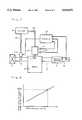
- FIG. 1shows a filter 1, an intake system 2, an engine 3, a fuel injection pump 4, an injector 5 for injecting fuel into an engine cylinder, an exhaust system 6, a catalytic converter 7, the outlet portion 8 of an exhaust pipe, a fuel tank 9, fuel pipes 10, an engine rotation sensor 11, a control lever sensor 12, a controller 13, and an injector 14 for injecting fuel into the intake system.
- the intake system 2includes an intake pipe and an intake manifold, and the exhaust system 6 includes the exhaust pipe and an exhaust manifold.
- the injector 14 associated with the intake system 2injects the same fuel as that which is injected into the engine 3.
- the fuel injected into the intake system 2 by the injector 14enters the cylinders of the engine in the form of a lean fuel-air mixture, but the greater part thereof remains uncombusted when leaving the engine into the exhaust system 6, unlike the fuel injected into the cylinders by the injector 5.
- the exhaust gases in the exhaust system 6contain a larger amount of hydrocarbon than the exhaust gases of an ordinary diesel engine having no such fuel injection as by the injector 14.
- the hydrocarbonis used for effective reduction in the catalytic converter 7.
- FIG. 2shows the number of revolutions of the engine and the torque thereby produced with the angle C 0 , C 1 , C 2 or C 3 of a control lever employed as a parameter.
- the relationship shown in FIG. 2is used for determining the torque, while the number of revolutions of the engine and the angle of the control lever are detected by the engine rotation sensor 11 and the control lever sensor 12, respectively. If, for example, the number of revolutions of the engine is N 1 , and the angle of the control lever, C 1 , the torque is T 1 , as indicated by broken lines; in FIG. 2.
- FIG. 3shows the number of revolutions of the employed as a parameter.
- the relationship shown in FIG. 3is used for determining the amount of NO x which is indicated by the curve on which the torque determined from FIG. 2 meets the number of revolutions of the engine as detected by the engine rotation sensor 11. If, for example, the torque is T 1 , and the number of revolutions of the on the curve indicating the amount of NO x as G 1 .
- FIG. 4shows the ratio of the amount of hydrocarbon relationship shown in FIG. 4 is used for determining the amount of hydrocarbon which is required, as will hereinafter be explained. It is obvious from FIG. 4 that an increase in the amount of hydrocarbon brings about a higher percentage of NO x removal The rise of the curve in FIG. 4, however, becomes more gradual, as it approaches a broken line indicating 100% of NO x removal. In other words, a larger amount of hydrocarbon becomes necessary to achieve a smaller increase in the percentage of NO x removal toward 100%. This is not desirable from the standpoint of efficiency. Therefore, the removal of NO x to 100% is not aimed at, but it is to achieve an appropriate percentage of NO x removal which is sufficiently high to satisfy the legal regulation concerning NO x .
- the necessary amount of hydrocarbonis, thus, determined from the intended level of NO x removal and the amount of NO x as determined from FIG. 3.
- FIG. 5shows the ratio of the amount of fuel injection into the intake system to that of fuel injection into the engine cylinders, and the amount of hydrocarbon which is required.
- FIG. 5is used for determining the above ratio from the necessary amount of hydrocarbon as determined from FIG. 4.
- the amount of fuel injection into the engine cylindersis the amount of fuel injected into the engine 3 which depends on the load of the engine.
- the load of the enginecan be ascertained from the number of revolutions of the engine which is determined by the engine rotation sensor 11, and the angle of the control lever which is determined by the control lever sensor 12.
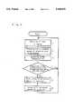
- FIG. 6showing the sequence of operation of the first example of apparatus embodying this invention.
- the sequenceconsists of the following steps:
- Step 1The load of the engine is determined from the number of revolutions of the engine as detected by the engine rotation sensor 11, and the angle of the control lever as detected by the control lever sensor 12.
- Step 2The standard amount of fuel injection by the injector 14 which is suitable for the load as detected in Step 1 is determined from a map which is prepared beforehand to show different amounts of injection for different loads of the engine.
- Step 3The amount (or concentration) of NO x is determined from FIGS. 2 and 3 based on the number of revolutions of the engine and the angle of the control lever which have been detected.
- Step 4The concentration of NO x as determined is compared with a predetermined value selected from the range which satisfies the relevant legal standard.
- the amount of hydrocarbon which is requireddepends on the predetermined value, as is obvious from FIG. 4. If the concentration as determined coincides with the predetermined value, the operation goes back to Step 1.
- Step 5If it does not coincide with the predetermined value, a corrective amount of fuel injection by the injector 14 is calculated.
- the corrective amountis a positive value if there is a shortage of hydrocarbon, while it is a negative value if there is an excess of hydrocarbon.
- Step 6The standard amount of fuel plus the corrective amount is injected into the intake system by the injector 14.
- FIG. 7showing a second example of an apparatus embodying this invention. It duplicates the first example shown in FIG. 1, as far as parts 1 to 14 are concerned. It can be distinguished in construction from the apparatus shown in FIG. 1 by further including a sensor 15 for NO x installed in the outlet portion 8 of the exhaust pipe downstream of the catalytic converter 7.
- FIG. 8shows the characteristics of the NO x sensor 15.
- the sensor 15has an electrical resistance, and its electrical resistance increases with an increase in the concentration (or amount) of NO x , as shown in FIG. 8.
- the concentration of NO xcan be determined from the electrical resistance shown by the sensor 15.
- FIG. 9showing the sequence of operation of the second example of apparatus embodying this invention which consists of the following steps:
- Step 1The load of the engine is determined from the number of revolutions thereof as detected by the engine rotation sensor 11, and the position of the control lever as detected by the control lever sensor 12.
- Step 2The standard amount of fuel injection by the injector 14 which is suitable for the load of the engine as detected in Step 1 is determined from a map which is prepared beforehand to show different amounts of injection for different loads of the engine.
- Step 3The concentration (or amount) of NO x in the exhaust pipe downstream of the catalytic converter 7 is detected by the NO x sensor 15 (see FIG. 8).
- Step 4The concentration of NO x as detected is compared with a predetermined value selected from the range which satisfies the relevant legal regulations.
- the amount of hydrocarbon which is requireddepends on the predetermined value, as is obvious from FIG. 4. If the concentration as detected coincides with the predetermined value, the operation goes back to Step 1.
- Step 5If it does not coincide with the predetermined value, a corrective amount of fuel injection by the injector 14 is calculated.
- the corrective amountis a positive value if there is a shortage of hydrocarbon, while it is a negative value if there is an excess of hydrocarbon.
- Step 6The standard amount of fuel plus the corrective amount is injected into the intake system by the injector 14.
- the first and second examples of apparatus embodying this inventionare applicable to a diesel engine, or a gasoline engine of the type having fuel injected into its cylinders, as opposed to an ordinary gasoline engine of the type having fuel injected into the intake system.
- FIG. 10A third example of an apparatus embodying this invention is shown in FIG. 10. It is identical in construction to the second example of an apparatus shown in FIG. 7, except for a fuel injector 16 associated with the exhaust system, and replacing the injector 14 associated with the intake system.
- the injector 16is associated with the exhaust system 6 upstream of the catalytic converter 7.
- the injection of fuel into the exhaust system 6 by the injector 16enables a larger amount of hydrocarbon to be produced in the exhaust system 6 than in any ordinary diesel engine having no such fuel injection.
- the exhaust gases which are rich in hydrocarbonenter the catalytic converter 7 in which the hydrocarbon has a reducing action on NO x .
- the approximate amount of NO x which the exhaust gases of the engine containcan be estimated from the load of the engine.
- the estimated amountcan be utilized to determine the approximate (or standard) amount of fuel injection by the injector 16.
- the load of the enginecan be ascertained from the number of revolutions thereof as detected by the engine rotation sensor 11, and the angle of the control lever as detected by the control lever sensor 12.
- FIG. 11shows the amount of fuel injection into the exhaust system which is required for obtaining the necessary amount of hydrocarbon which is determined from FIG. 4.
- the NO x sensor 15detects the concentration of NO x in the exhaust gases leaving the catalytic converter 7, as has been described with reference to FIG. 8.
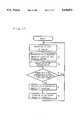
- FIG. 12shows the sequence of operation of the third example of apparatus embodying this invention which consists of the following steps:
- Step 1The load of the engine is ascertained from the number of revolutions thereof as detected by the engine rotation sensor 11, and the angle of the control lever as detected by the control lever sensor 12.
- Step 2The standard amount of fuel injection by the injector 16 which is suitable for the load of the engine as detected in Step 1 is determined from a map which is prepared beforehand to show different amounts of injection for different loads of the engine.
- Step 3The concentration (or amount) of NO x in the exhaust pipe downstream of the catalytic converter 7 is detected by the NO x sensor 15 (see FIG. 8).
- Step 4The concentration of NO x as detected is compared with a predetermined value selected from the range which satisfies the relevant legal regulations.
- the amount of hydrocarbon which is requireddepends on the predetermined value, as is obvious from FIG. 4. If the concentration as detected coincides with the predetermined value, the operation goes back to Step 1.
- Step 5If it does not coincide with the predetermined value, a corrective amount of fuel injection by the injector 16 is calculated.
- the corrective amountis a positive value if there is a shortage of hydrocarbon, while it is a negative value if there is an excess of hydrocarbon.
- Step 6The standard amount of fuel plus the corrective amount is injected into the exhaust system by the injector 16.
- the third example of apparatus embodying this inventionis applicable to not only a diesel engine, but also any other type of engine, including an ordinary gasoline engine, since it is into the exhaust system that fuel is injected to produce hydrocarbon as required by the catalytic converter.
Landscapes
- Engineering & Computer Science (AREA)
- Chemical & Material Sciences (AREA)
- Combustion & Propulsion (AREA)
- Mechanical Engineering (AREA)
- General Engineering & Computer Science (AREA)
- Chemical Kinetics & Catalysis (AREA)
- Health & Medical Sciences (AREA)
- Toxicology (AREA)
- Exhaust Gas After Treatment (AREA)
Abstract
Description
1. Technical Field
This invention relates to an apparatus for diminishing the amount of nitrogen oxides (NOx) in the exhaust gases of an automobile.
2. Background Art
There is known an apparatus which is designed for diminishing the amount of NOx in the exhaust gases of a diesel engine by supplying a reducing agent, such as ammonia, into the exhaust gases. For example, the Japanese Patent Application laid open under No. 83816/1989 discloses an by an NOx analyzer, and blows ammonia into the exhaust gases apparatus which detects the amount of NOx in exhaust gases in accordance with the amount of NO as detected. The use of ammonia, however, calls for a great deal of care, as it has an objectionable odor.
There is also known an apparatus which relies upon a catalytic converter incorporated in the exhaust system of an automobile for diminishing the amount of NOx in its exhaust gases. The catalytic converter relies upon hydrocarbon for its reducing action, but the exhaust gases do not contain a sufficiently large amount of hydrocarbon for the action of the catalytic converter. Therefore, the known apparatus fails to diminish the amount of NOx effectively.
It is, therefore, an object of this invention to provide an apparatus which can supply a sufficiently large amount of hydrocarbon for a catalytic converter to effectively diminish the amount of NOx.
According to a first aspect of this invention, the object thereof is attained by an apparatus for diminishing the amount of NOx in the exhaust gases of an engine of the type in which fuel is injected into its cylinders, which comprises an injector associated with the intake system of the engine for injecting fuel into the intake system, means for calculating the amount of NOx in the exhaust gases from the rotating speed of the engine and the angle of a control lever, and means for controlling the injection of the fuel by the injector in accordance with the load of the engine and the amount of NOx as calculated.
According to a second aspect of this invention, there is also provided an apparatus for diminishing the amount of NOx in the exhaust gases of an engine of the type as defined above, which comprises an injector associated with the intake system of the engine for injecting fuel into the intake system, a sensor for NOx installed downstream of a catalytic converter in the exhaust pipe of the engine, and a controller for controlling the injection of the fuel by the injector in accordance with the load of the engine and the output of the sensor.
According to a third aspect of this invention, there is provided an apparatus for diminishing the amount of NO2 in the exhaust gases of an engine, which comprises an injector associated with the exhaust system of the engine for injecting fuel into the exhaust system between the engine and a catalytic converter in the exhaust pipe of the engine, a sensor for NOx installed downstream of the catalytic converter, and means for controlling the injection of the fuel by the injector in accordance with the load of the engine and the output of the sensor.
The material employed in the apparatus of this invention for diminishing NOx is a common fuel which is easy to handle, since it does not have an objectionable odor such as that present when ammonia is used. The injection of the fuel into the intake or exhaust system of the engine also produces the effect of diminishing smoke.
FIG. 1 is a diagram showing a first example of an apparatus embodying this invention;
FIG. 2 is a graph showing the relation as observed between the rotating speed (number of revolutions) of an engine and the torque thereby produced, when the angle of a control lever is employed as a parameter;
FIG. 3 is a graph similar to FIG. 2, but showing the relation when the amount of NOx is employed as a parameter;
FIG. 4 is a graph showing the percentage of NOx removal in relation to the ratio of the amount of hydrocarbon to that of NOx ;
FIG. 5 is a graph showing the amount of hydrocarbon in relation to the ratio of the amount of injection into the intake system of an engine to that of injection into its cylinders;
FIG. 6 is a flow chart showing the operation of the apparatus according to the first example;
FIG. 7 is a diagram showing a second example of an apparatus embodying this invention;
FIG. 8 is a graph showing the characteristics of a sensor for NOx ;
FIG. 9 is a flow chart showing the operation of the apparatus according to the second example;
FIG. 10 is a diagram showing a third example of an apparatus embodying this invention;
FIG. 11 is a graph showing the amount of hydrocarbon in relation to the amount of injection into the exhaust system of an engine; and
FIG. 12 is a flow chart showing the operation of the apparatus according to the third example.
It is known that zeolite forms a catalyst which is useful for diminishing the amount of NOx in the exhaust gases of a diesel engine, and the non-selective catalytic reduction which employs a zeolite catalyst is expected to be an effective method for that purpose. This method is carried out in the presence of carbon monoxide, hydrocarbon, hydrogen or carbon, and hydrocarbon, among others, plays an important role in the catalytic reduction of NOx.
The effective reduction of NOx requires the presence of hydrocarbon in an amount which is larger than that of the NOx to be reduced. The amount of hydrocarbon which usually occurs in a diesel engine is, however, smaller than that of the NOx which its exhaust gases usually contain. It is, therefore, necessary to supply an additional amount of hydrocarbon for the effective reduction of NOx. According to this invention, the additional supply of hydrocarbon is effected by the injection of fuel into the intake system of an engine, or into its exhaust system upstream of a catalytic converter.
Description will now be made of a number of examples of apparatus embodying this invention with reference to the accompanying drawings.
Reference is first made to FIG. 1 showing a first example of apparatus embodying this invention. FIG. 1 shows afilter 1, anintake system 2, anengine 3, afuel injection pump 4, aninjector 5 for injecting fuel into an engine cylinder, anexhaust system 6, acatalytic converter 7, theoutlet portion 8 of an exhaust pipe, a fuel tank 9,fuel pipes 10, anengine rotation sensor 11, acontrol lever sensor 12, acontroller 13, and aninjector 14 for injecting fuel into the intake system.
Theintake system 2 includes an intake pipe and an intake manifold, and theexhaust system 6 includes the exhaust pipe and an exhaust manifold. Theinjector 14 associated with theintake system 2 injects the same fuel as that which is injected into theengine 3.
The fuel injected into theintake system 2 by theinjector 14 enters the cylinders of the engine in the form of a lean fuel-air mixture, but the greater part thereof remains uncombusted when leaving the engine into theexhaust system 6, unlike the fuel injected into the cylinders by theinjector 5. As a result, the exhaust gases in theexhaust system 6 contain a larger amount of hydrocarbon than the exhaust gases of an ordinary diesel engine having no such fuel injection as by theinjector 14. The hydrocarbon is used for effective reduction in thecatalytic converter 7.
FIG. 2 shows the number of revolutions of the engine and the torque thereby produced with the angle C0, C1, C2 or C3 of a control lever employed as a parameter. The relationship shown in FIG. 2 is used for determining the torque, while the number of revolutions of the engine and the angle of the control lever are detected by theengine rotation sensor 11 and thecontrol lever sensor 12, respectively. If, for example, the number of revolutions of the engine is N1, and the angle of the control lever, C1, the torque is T1, as indicated by broken lines; in FIG. 2.
FIG. 3 shows the number of revolutions of the employed as a parameter. The relationship shown in FIG. 3 is used for determining the amount of NOx which is indicated by the curve on which the torque determined from FIG. 2 meets the number of revolutions of the engine as detected by theengine rotation sensor 11. If, for example, the torque is T1, and the number of revolutions of the on the curve indicating the amount of NOx as G1.
FIG. 4 shows the ratio of the amount of hydrocarbon relationship shown in FIG. 4 is used for determining the amount of hydrocarbon which is required, as will hereinafter be explained. It is obvious from FIG. 4 that an increase in the amount of hydrocarbon brings about a higher percentage of NOx removal The rise of the curve in FIG. 4, however, becomes more gradual, as it approaches a broken line indicating 100% of NOx removal. In other words, a larger amount of hydrocarbon becomes necessary to achieve a smaller increase in the percentage of NOx removal toward 100%. This is not desirable from the standpoint of efficiency. Therefore, the removal of NOx to 100% is not aimed at, but it is to achieve an appropriate percentage of NOx removal which is sufficiently high to satisfy the legal regulation concerning NOx. The necessary amount of hydrocarbon is, thus, determined from the intended level of NOx removal and the amount of NOx as determined from FIG. 3.
FIG. 5 shows the ratio of the amount of fuel injection into the intake system to that of fuel injection into the engine cylinders, and the amount of hydrocarbon which is required. FIG. 5 is used for determining the above ratio from the necessary amount of hydrocarbon as determined from FIG. 4. The amount of fuel injection into the engine cylinders is the amount of fuel injected into theengine 3 which depends on the load of the engine. The load of the engine can be ascertained from the number of revolutions of the engine which is determined by theengine rotation sensor 11, and the angle of the control lever which is determined by thecontrol lever sensor 12.
Attention is now directed to FIG. 6 showing the sequence of operation of the first example of apparatus embodying this invention. The sequence consists of the following steps:
Step 1: The load of the engine is determined from the number of revolutions of the engine as detected by theengine rotation sensor 11, and the angle of the control lever as detected by thecontrol lever sensor 12.
Step 2: The standard amount of fuel injection by theinjector 14 which is suitable for the load as detected inStep 1 is determined from a map which is prepared beforehand to show different amounts of injection for different loads of the engine.
Step 3: The amount (or concentration) of NOx is determined from FIGS. 2 and 3 based on the number of revolutions of the engine and the angle of the control lever which have been detected.
Step 4: The concentration of NOx as determined is compared with a predetermined value selected from the range which satisfies the relevant legal standard. The amount of hydrocarbon which is required depends on the predetermined value, as is obvious from FIG. 4. If the concentration as determined coincides with the predetermined value, the operation goes back toStep 1.
Step 5: If it does not coincide with the predetermined value, a corrective amount of fuel injection by theinjector 14 is calculated. The corrective amount is a positive value if there is a shortage of hydrocarbon, while it is a negative value if there is an excess of hydrocarbon.
Step 6: The standard amount of fuel plus the corrective amount is injected into the intake system by theinjector 14.
Reference is now made to FIG. 7 showing a second example of an apparatus embodying this invention. It duplicates the first example shown in FIG. 1, as far asparts 1 to 14 are concerned. It can be distinguished in construction from the apparatus shown in FIG. 1 by further including asensor 15 for NOx installed in theoutlet portion 8 of the exhaust pipe downstream of thecatalytic converter 7.
FIG. 8 shows the characteristics of the NOx sensor 15. Thesensor 15 has an electrical resistance, and its electrical resistance increases with an increase in the concentration (or amount) of NOx, as shown in FIG. 8. Thus, the concentration of NOx can be determined from the electrical resistance shown by thesensor 15.
The relationships shown in FIGS. 4 and 5 are applicable to the second example, too.
Attention is now directed to FIG. 9 showing the sequence of operation of the second example of apparatus embodying this invention which consists of the following steps:
Step 1: The load of the engine is determined from the number of revolutions thereof as detected by theengine rotation sensor 11, and the position of the control lever as detected by thecontrol lever sensor 12.
Step 2: The standard amount of fuel injection by theinjector 14 which is suitable for the load of the engine as detected inStep 1 is determined from a map which is prepared beforehand to show different amounts of injection for different loads of the engine.
Step 3: The concentration (or amount) of NOx in the exhaust pipe downstream of thecatalytic converter 7 is detected by the NOx sensor 15 (see FIG. 8).
Step 4: The concentration of NOx as detected is compared with a predetermined value selected from the range which satisfies the relevant legal regulations. The amount of hydrocarbon which is required depends on the predetermined value, as is obvious from FIG. 4. If the concentration as detected coincides with the predetermined value, the operation goes back toStep 1.
Step 5: If it does not coincide with the predetermined value, a corrective amount of fuel injection by theinjector 14 is calculated. The corrective amount is a positive value if there is a shortage of hydrocarbon, while it is a negative value if there is an excess of hydrocarbon.
Step 6: The standard amount of fuel plus the corrective amount is injected into the intake system by theinjector 14.
The first and second examples of apparatus embodying this invention are applicable to a diesel engine, or a gasoline engine of the type having fuel injected into its cylinders, as opposed to an ordinary gasoline engine of the type having fuel injected into the intake system.
A third example of an apparatus embodying this invention is shown in FIG. 10. It is identical in construction to the second example of an apparatus shown in FIG. 7, except for afuel injector 16 associated with the exhaust system, and replacing theinjector 14 associated with the intake system. Theinjector 16 is associated with theexhaust system 6 upstream of thecatalytic converter 7.
The injection of fuel into theexhaust system 6 by theinjector 16 enables a larger amount of hydrocarbon to be produced in theexhaust system 6 than in any ordinary diesel engine having no such fuel injection. The exhaust gases which are rich in hydrocarbon enter thecatalytic converter 7 in which the hydrocarbon has a reducing action on NOx.
The approximate amount of NOx which the exhaust gases of the engine contain can be estimated from the load of the engine. The estimated amount can be utilized to determine the approximate (or standard) amount of fuel injection by theinjector 16. The load of the engine can be ascertained from the number of revolutions thereof as detected by theengine rotation sensor 11, and the angle of the control lever as detected by thecontrol lever sensor 12.
FIG. 11 shows the amount of fuel injection into the exhaust system which is required for obtaining the necessary amount of hydrocarbon which is determined from FIG. 4. The NOx sensor 15 detects the concentration of NOx in the exhaust gases leaving thecatalytic converter 7, as has been described with reference to FIG. 8.
FIG. 12 shows the sequence of operation of the third example of apparatus embodying this invention which consists of the following steps:
Step 1: The load of the engine is ascertained from the number of revolutions thereof as detected by theengine rotation sensor 11, and the angle of the control lever as detected by thecontrol lever sensor 12.
Step 2: The standard amount of fuel injection by theinjector 16 which is suitable for the load of the engine as detected inStep 1 is determined from a map which is prepared beforehand to show different amounts of injection for different loads of the engine.
Step 3: The concentration (or amount) of NOx in the exhaust pipe downstream of thecatalytic converter 7 is detected by the NOx sensor 15 (see FIG. 8).
Step 4: The concentration of NOx as detected is compared with a predetermined value selected from the range which satisfies the relevant legal regulations. The amount of hydrocarbon which is required depends on the predetermined value, as is obvious from FIG. 4. If the concentration as detected coincides with the predetermined value, the operation goes back toStep 1.
Step 5: If it does not coincide with the predetermined value, a corrective amount of fuel injection by theinjector 16 is calculated. The corrective amount is a positive value if there is a shortage of hydrocarbon, while it is a negative value if there is an excess of hydrocarbon.
Step 6: The standard amount of fuel plus the corrective amount is injected into the exhaust system by theinjector 16.
The third example of apparatus embodying this invention is applicable to not only a diesel engine, but also any other type of engine, including an ordinary gasoline engine, since it is into the exhaust system that fuel is injected to produce hydrocarbon as required by the catalytic converter.
Claims (9)
1. In an apparatus for diminishing the amount of nitrogen oxides in the exhaust gases of an engine of the type having fuel injected into its cylinders, the improvement which comprises an injector associated with the intake system of the engine for injecting fuel into said intake system; means for determining said amount of nitrogen oxides from the number of revolutions of the engine and the angle of a control lever; and means for controlling the amount of fuel injection by said injector in accordance with the load of the engine and said amount of nitrogen oxides as determined.
2. In an apparatus for diminishing the amount of nitrogen oxides in the exhaust gases of an engine of the type having fuel injected into its cylinders, the improvement which comprises an injector associated with the intake system of the engine for injecting fuel into said intake system; a sensor for nitrogen oxides installed in the exhaust system of the engine downstream of a catalytic converter for detecting the concentration of nitrogen oxides in the exhaust gases leaving said converter; and means for controlling the amount of fuel injection by said injector in accordance with the load of the engine and the output of said sensor.
3. In an apparatus for diminishing the amount of nitrogen oxides in the exhaust gases of an engine, the improvement which comprises an injector associated with the exhaust system of the engine for injecting fuel into said exhaust system upstream of a catalytic converter; a sensor for nitrogen oxides installed in said exhaust system downstream of said converter for detecting the concentration of nitrogen oxides in the exhaust gases leaving said converter; and means for controlling the amount of fuel injection by said injector in accordance with the load of the engine and the output of said sensor.
4. In an apparatus for diminishing the amount of nitrogen oxides in exhaust gases of a fuel injected engine having a load applied thereto, said engine having a cylinder, an intake system and an exhaust system, the improvement which comprises an injector associated with one of the intake system and the exhaust system of the engine for injecting fuel into one of said intake and exhaust systems; means for determining the amount of nitrogen oxides in the exhaust gases; and means for controlling the amount of fuel injected by said injector in accordance with the load of the engine and the amount of nitrogen oxides in the exhaust gases.
5. The apparatus defined by claim 4 wherein the means for determining the amount of nitrogen oxides in the exhaust gases of said engine is a sensor for nitrogen oxides installed in the exhaust system of the engine downstream of a catalytic converter.
6. The apparatus defined by claim 5 wherein said injector is associated with the intake system of said engine for injecting fuel into said intake system.
7. The apparatus defined by claim 5 wherein said injector is associated with the exhaust system of said engine for injecting fuel into said exhaust system.
8. The apparatus defined by claim 4 which further comprises a controller, an engine rotation sensor and a control lever sensor, said controller controlling the amount of fuel injected by said injector in accordance with the outputs of said rotation and control lever sensors.
9. The apparatus defined by claim 5 which further comprises a controller, an engine rotation sensor and a control lever sensor, said controller controlling the amount of fuel injected by said injector in accordance with the outputs of said rotation, control lever and nitrogen oxide sensors.
Applications Claiming Priority (7)
| Application Number | Priority Date | Filing Date | Title |
|---|---|---|---|
| JP3-160088 | 1991-06-03 | ||
| JP3160088AJP2638338B2 (en) | 1991-06-03 | 1991-06-03 | NOx reduction device |
| JP3-161028 | 1991-06-05 | ||
| JP3-161027 | 1991-06-05 | ||
| JP3161027AJP2638340B2 (en) | 1991-06-05 | 1991-06-05 | NOx reduction device |
| JP3161028AJPH04358716A (en) | 1991-06-05 | 1991-06-05 | Nox decreasing device |
| PCT/JP1992/000708WO1992021871A1 (en) | 1991-06-03 | 1992-06-01 | DEVICE FOR REDUCING NO¿x? |
Publications (1)
| Publication Number | Publication Date |
|---|---|
| US5410873Atrue US5410873A (en) | 1995-05-02 |
Family
ID=27321632
Family Applications (1)
| Application Number | Title | Priority Date | Filing Date |
|---|---|---|---|
| US08/146,097Expired - Fee RelatedUS5410873A (en) | 1991-06-03 | 1992-06-01 | Apparatus for diminishing nitrogen oxides |
Country Status (3)
| Country | Link |
|---|---|
| US (1) | US5410873A (en) |
| EP (1) | EP0683311A1 (en) |
| WO (1) | WO1992021871A1 (en) |
Cited By (87)
| Publication number | Priority date | Publication date | Assignee | Title |
|---|---|---|---|---|
| US5540047A (en)* | 1993-10-06 | 1996-07-30 | Siemens Aktiengesellschaft | Method for reducing the nitrogen oxide concentration in the exhaust of an internal combustion engine or of a firing system |
| WO1997039226A1 (en)* | 1996-04-02 | 1997-10-23 | Kleenair Systems, Inc. | AMMONIA INJECTION IN NOx CONTROL |
| US5778667A (en)* | 1996-06-18 | 1998-07-14 | Toyota Jidosha Kabushiki, Kaisha | Method and a device for purifying combustion exhaust gas |
| EP0831226A3 (en)* | 1996-08-20 | 1999-05-12 | Toyota Jidosha Kabushiki Kaisha | A fuel injection control device for a direct injection type engine |
| US5953907A (en)* | 1996-06-21 | 1999-09-21 | Ngk Insulators, Ltd. | Method of controlling an engine exhaust gas system and method of detecting deterioration of catalyst/adsorbing means |
| US5964088A (en)* | 1996-03-22 | 1999-10-12 | Toyota Jidosha Kabushiki Kaisha | Device for purifying exhaust gas of engine |
| US5974793A (en)* | 1996-04-19 | 1999-11-02 | Toyota Jidosha Kabushiki Kaisha | Exhaust gas purification device for an internal combustion engine |
| US6041592A (en)* | 1996-12-20 | 2000-03-28 | Bayerische Motoren Ag | Control system and method for an NOx accumulator |
| US6047542A (en)* | 1995-11-17 | 2000-04-11 | Toyota Jidosha Kabushiki Kaisha | Method and device for purifying exhaust gas of engine |
| US6053144A (en)* | 1998-11-05 | 2000-04-25 | Caterpillar Inc. | Diesel engine with a combustor which provides combustion products to reduce NOx production in a combustion chamber |
| US6109024A (en)* | 1997-05-12 | 2000-08-29 | Toyota Jidosha Kabushiki Kaisha | Exhaust gas purification device for an internal combustion engine |
| US6119452A (en)* | 1995-11-17 | 2000-09-19 | Toyota Jidosha Kabushiki Kaisha | Device for purifying exhaust gas of internal combustion engine |
| US6133185A (en)* | 1995-11-09 | 2000-10-17 | Toyota Jidosha Kabushiki Kaisha | Exhaust gas purifying catalyst |
| US6192676B1 (en)* | 1998-02-25 | 2001-02-27 | Siemens Aktiengesellschaft | Device for reducing the NOx content in the exhaust gas of an internal combustion engine |
| US6209313B1 (en)* | 1997-11-07 | 2001-04-03 | Siemens Aktiengesellschaft | Method of reducing the Nox content in the exhaust gas of a diesel internal combustion engine |
| US6247303B1 (en)* | 1997-05-16 | 2001-06-19 | Siemens Aktiengesellschaft | Method and device for removing oxidic noxious substances in an oxygen-containing exhaust gas and engine which is operated therewith |
| US6308515B1 (en) | 2000-03-17 | 2001-10-30 | Ford Global Technologies, Inc. | Method and apparatus for accessing ability of lean NOx trap to store exhaust gas constituent |
| US6308697B1 (en) | 2000-03-17 | 2001-10-30 | Ford Global Technologies, Inc. | Method for improved air-fuel ratio control in engines |
| US6327847B1 (en) | 2000-03-17 | 2001-12-11 | Ford Global Technologies, Inc. | Method for improved performance of a vehicle |
| US20020007628A1 (en)* | 2000-03-17 | 2002-01-24 | Bidner David Karl | Method for determining emission control system operability |
| US6345496B1 (en) | 1995-11-09 | 2002-02-12 | Toyota Jidosha Kabushiki Kaisha | Method and device for purifying exhaust gas of an engine |
| US6360529B1 (en) | 2000-03-17 | 2002-03-26 | Ford Global Technologies, Inc. | Method and apparatus for enabling lean engine operation upon engine start-up |
| US6360530B1 (en) | 2000-03-17 | 2002-03-26 | Ford Global Technologies, Inc. | Method and apparatus for measuring lean-burn engine emissions |
| US6374597B1 (en) | 2000-03-17 | 2002-04-23 | Ford Global Technologies, Inc. | Method and apparatus for accessing ability of lean NOx trap to store exhaust gas constituent |
| US6389802B1 (en)* | 1998-09-25 | 2002-05-21 | Robert Bosch Gmbh | Method and arrangement for operating an internal combustion engine in combination with an NOx storage catalytic converter and an NOx sensor |
| US6408615B1 (en)* | 1998-02-27 | 2002-06-25 | Volkswagen Ag | Method for controlling an NOx accumulating catalytic converter |
| US6427437B1 (en) | 2000-03-17 | 2002-08-06 | Ford Global Technologies, Inc. | Method for improved performance of an engine emission control system |
| US6434930B1 (en) | 2000-03-17 | 2002-08-20 | Ford Global Technologies, Inc. | Method and apparatus for controlling lean operation of an internal combustion engine |
| US6438944B1 (en) | 2000-03-17 | 2002-08-27 | Ford Global Technologies, Inc. | Method and apparatus for optimizing purge fuel for purging emissions control device |
| US6438947B2 (en)* | 1998-11-09 | 2002-08-27 | Siemens Aktiengesellschaft | Method for adapting a raw NOx concentration value of an internal combustion engine operating with an excess of air |
| US6449945B1 (en)* | 2001-04-18 | 2002-09-17 | Ford Global Technologies, Inc. | Emission control system |
| US6453666B1 (en) | 2001-06-19 | 2002-09-24 | Ford Global Technologies, Inc. | Method and system for reducing vehicle tailpipe emissions when operating lean |
| US6463733B1 (en) | 2001-06-19 | 2002-10-15 | Ford Global Technologies, Inc. | Method and system for optimizing open-loop fill and purge times for an emission control device |
| US6467259B1 (en) | 2001-06-19 | 2002-10-22 | Ford Global Technologies, Inc. | Method and system for operating dual-exhaust engine |
| US6477832B1 (en) | 2000-03-17 | 2002-11-12 | Ford Global Technologies, Inc. | Method for improved performance of a vehicle having an internal combustion engine |
| US6481199B1 (en) | 2000-03-17 | 2002-11-19 | Ford Global Technologies, Inc. | Control for improved vehicle performance |
| US6487853B1 (en) | 2001-06-19 | 2002-12-03 | Ford Global Technologies. Inc. | Method and system for reducing lean-burn vehicle emissions using a downstream reductant sensor |
| US6487852B1 (en) | 2001-09-04 | 2002-12-03 | Ford Global Technologies, Inc. | Method and apparatus for controlling reactant injection into an active lean NOx catalyst |
| US6487850B1 (en) | 2000-03-17 | 2002-12-03 | Ford Global Technologies, Inc. | Method for improved engine control |
| US6487849B1 (en) | 2000-03-17 | 2002-12-03 | Ford Global Technologies, Inc. | Method and apparatus for controlling lean-burn engine based upon predicted performance impact and trap efficiency |
| US6490860B1 (en) | 2001-06-19 | 2002-12-10 | Ford Global Technologies, Inc. | Open-loop method and system for controlling the storage and release cycles of an emission control device |
| US6499293B1 (en) | 2000-03-17 | 2002-12-31 | Ford Global Technologies, Inc. | Method and system for reducing NOx tailpipe emissions of a lean-burn internal combustion engine |
| US6502387B1 (en) | 2001-06-19 | 2003-01-07 | Ford Global Technologies, Inc. | Method and system for controlling storage and release of exhaust gas constituents in an emission control device |
| US6502386B1 (en)* | 2000-08-02 | 2003-01-07 | Ford Global Technologies, Inc. | Catalyst monitoring in a diesel engine |
| US6516607B1 (en)* | 1998-04-22 | 2003-02-11 | Emitec Gesellschaft Fuer Emissionstechnologies Mbh | Method and device for cleaning exhaust gas containing nitrogen oxide from an internal combustion engine |
| US6539704B1 (en) | 2000-03-17 | 2003-04-01 | Ford Global Technologies, Inc. | Method for improved vehicle performance |
| US6539706B2 (en) | 2001-06-19 | 2003-04-01 | Ford Global Technologies, Inc. | Method and system for preconditioning an emission control device for operation about stoichiometry |
| US6546718B2 (en) | 2001-06-19 | 2003-04-15 | Ford Global Technologies, Inc. | Method and system for reducing vehicle emissions using a sensor downstream of an emission control device |
| US6546720B2 (en) | 2001-09-04 | 2003-04-15 | Ford Global Technologies, Inc. | Method and apparatus for controlling the amount of reactant to be added to a substance using a sensor which is responsive to both the reactant and the substance |
| US6553754B2 (en) | 2001-06-19 | 2003-04-29 | Ford Global Technologies, Inc. | Method and system for controlling an emission control device based on depletion of device storage capacity |
| US6568177B1 (en) | 2002-06-04 | 2003-05-27 | Ford Global Technologies, Llc | Method for rapid catalyst heating |
| US6594985B2 (en)* | 2001-06-19 | 2003-07-22 | Ford Global Technologies, Inc. | Exhaust gas aftertreatment device efficiency estimation |
| US6594989B1 (en) | 2000-03-17 | 2003-07-22 | Ford Global Technologies, Llc | Method and apparatus for enhancing fuel economy of a lean burn internal combustion engine |
| US6604504B2 (en) | 2001-06-19 | 2003-08-12 | Ford Global Technologies, Llc | Method and system for transitioning between lean and stoichiometric operation of a lean-burn engine |
| US6615577B2 (en) | 2001-06-19 | 2003-09-09 | Ford Global Technologies, Llc | Method and system for controlling a regeneration cycle of an emission control device |
| US6629453B1 (en) | 2000-03-17 | 2003-10-07 | Ford Global Technologies, Llc | Method and apparatus for measuring the performance of an emissions control device |
| US6650991B2 (en) | 2001-06-19 | 2003-11-18 | Ford Global Technologies, Llc | Closed-loop method and system for purging a vehicle emission control |
| US20030221416A1 (en)* | 2002-06-04 | 2003-12-04 | Ford Global Technologies, Inc. | Method and system for rapid heating of an emission control device |
| US20030221671A1 (en)* | 2002-06-04 | 2003-12-04 | Ford Global Technologies, Inc. | Method for controlling an engine to obtain rapid catalyst heating |
| US20030221419A1 (en)* | 2002-06-04 | 2003-12-04 | Ford Global Technologies, Inc. | Method for controlling the temperature of an emission control device |
| US6658841B2 (en)* | 1999-07-07 | 2003-12-09 | Siemens Aktiengesellschaft | Method for checking a three-way exhaust catalytic converter of an internal-combustion engine |
| US6691020B2 (en) | 2001-06-19 | 2004-02-10 | Ford Global Technologies, Llc | Method and system for optimizing purge of exhaust gas constituent stored in an emission control device |
| US6694244B2 (en) | 2001-06-19 | 2004-02-17 | Ford Global Technologies, Llc | Method for quantifying oxygen stored in a vehicle emission control device |
| US6691507B1 (en) | 2000-10-16 | 2004-02-17 | Ford Global Technologies, Llc | Closed-loop temperature control for an emission control device |
| US6698191B2 (en)* | 2001-08-09 | 2004-03-02 | Ford Global Technologies, Llc | High efficiency conversion of nitrogen oxides in an exhaust aftertreatment device at low temperature |
| US6708483B1 (en) | 2000-03-17 | 2004-03-23 | Ford Global Technologies, Llc | Method and apparatus for controlling lean-burn engine based upon predicted performance impact |
| US6715462B2 (en) | 2002-06-04 | 2004-04-06 | Ford Global Technologies, Llc | Method to control fuel vapor purging |
| US6725830B2 (en) | 2002-06-04 | 2004-04-27 | Ford Global Technologies, Llc | Method for split ignition timing for idle speed control of an engine |
| US6732508B2 (en)* | 2001-05-16 | 2004-05-11 | Cooper Cameron Corporation | Exhaust system for an internal combustion engine and engine comprising the same |
| US6736120B2 (en) | 2002-06-04 | 2004-05-18 | Ford Global Technologies, Llc | Method and system of adaptive learning for engine exhaust gas sensors |
| US6736121B2 (en) | 2002-06-04 | 2004-05-18 | Ford Global Technologies, Llc | Method for air-fuel ratio sensor diagnosis |
| US6735938B2 (en) | 2002-06-04 | 2004-05-18 | Ford Global Technologies, Llc | Method to control transitions between modes of operation of an engine |
| US6745747B2 (en) | 2002-06-04 | 2004-06-08 | Ford Global Technologies, Llc | Method for air-fuel ratio control of a lean burn engine |
| US6758185B2 (en) | 2002-06-04 | 2004-07-06 | Ford Global Technologies, Llc | Method to improve fuel economy in lean burn engines with variable-displacement-like characteristics |
| US6769398B2 (en) | 2002-06-04 | 2004-08-03 | Ford Global Technologies, Llc | Idle speed control for lean burn engine with variable-displacement-like characteristic |
| US6834498B2 (en) | 2002-11-21 | 2004-12-28 | Ford Global Technologies, Llc | Diesel aftertreatment systems |
| US6843051B1 (en) | 2000-03-17 | 2005-01-18 | Ford Global Technologies, Llc | Method and apparatus for controlling lean-burn engine to purge trap of stored NOx |
| US6860100B1 (en) | 2000-03-17 | 2005-03-01 | Ford Global Technologies, Llc | Degradation detection method for an engine having a NOx sensor |
| US6862879B2 (en) | 2002-11-21 | 2005-03-08 | Ford Global Technologies, Llc | Diesel aftertreatment system |
| US6868827B2 (en) | 2002-06-04 | 2005-03-22 | Ford Global Technologies, Llc | Method for controlling transitions between operating modes of an engine for rapid heating of an emission control device |
| US6895747B2 (en) | 2002-11-21 | 2005-05-24 | Ford Global Technologies, Llc | Diesel aftertreatment systems |
| US6925982B2 (en) | 2002-06-04 | 2005-08-09 | Ford Global Technologies, Llc | Overall scheduling of a lean burn engine system |
| US20060042234A1 (en)* | 2004-08-31 | 2006-03-02 | Qingwen Song | Control system for an engine aftertreatment system |
| US20060218905A1 (en)* | 2001-05-04 | 2006-10-05 | Nco2 Company Llc | Method and system for obtaining exhaust gas for use in augmenting crude oil production |
| US7121085B2 (en) | 2001-09-04 | 2006-10-17 | Ford Global Technologies, Llc | Method and apparatus for controlling hydrocarbon injection into engine exhaust to reduce NOx |
| US20080066454A1 (en)* | 2006-09-20 | 2008-03-20 | Gm Global Technology Operations, Inc. | Apparatus and Method to Inject a Reductant into an Exhaust Gas Feedstream |
| US20200291877A1 (en)* | 2019-03-12 | 2020-09-17 | GM Global Technology Operations LLC | Aggressive thermal heating target strategy based on nox estimated feedback |
Families Citing this family (4)
| Publication number | Priority date | Publication date | Assignee | Title |
|---|---|---|---|---|
| JP3079933B2 (en)* | 1995-02-14 | 2000-08-21 | トヨタ自動車株式会社 | Exhaust gas purification device for internal combustion engine |
| FR2731746B1 (en)* | 1995-03-17 | 1997-04-11 | Renault | EXHAUST DEVICE FOR A COMBUSTION ENGINE |
| DE19547646A1 (en)* | 1995-12-20 | 1997-06-26 | Bosch Gmbh Robert | Method of controlling an IC engine |
| JP2006283663A (en)* | 2005-03-31 | 2006-10-19 | Toyota Industries Corp | Exhaust gas purification device in internal combustion engine |
Citations (11)
| Publication number | Priority date | Publication date | Assignee | Title |
|---|---|---|---|---|
| US3982393A (en)* | 1973-12-21 | 1976-09-28 | Nissan Motor Co., Ltd. | Internal combustion engine exhaust cleaning method and system |
| US4051672A (en)* | 1974-09-20 | 1977-10-04 | Nissan Motor Company, Limited | Multi-cylinder internal combustion engine |
| US4134261A (en)* | 1976-09-13 | 1979-01-16 | Nissan Motor Company, Limited | Variable displacement closed loop fuel controlled internal combustion engine |
| JPS5593917A (en)* | 1979-01-08 | 1980-07-16 | Unitika Ltd | Method of purifying exhaust gas of internal combustion engine |
| JPS57168040A (en)* | 1981-04-10 | 1982-10-16 | Nippon Kokan Kk <Nkk> | Method to determine combustion condition of diesel engine |
| JPS586045A (en)* | 1981-07-02 | 1983-01-13 | 近藤 孝 | Vehicle charger |
| JPS6028243A (en)* | 1983-07-01 | 1985-02-13 | モトロ−ラ・インコ−ポレ−テツド | Microcell array |
| JPS61197740A (en)* | 1985-02-25 | 1986-09-02 | Toyota Motor Corp | Internal combustion engine exhaust gas purification device |
| US4756155A (en)* | 1985-03-26 | 1988-07-12 | Nissan Motor Company, Ltd. | Exhaust particle removing system for an internal combustion engine |
| JPS6483816A (en)* | 1987-09-28 | 1989-03-29 | Nippon Kokan Kk | Exhaust gas purifying method for internal combustion engine |
| JPH03217640A (en)* | 1990-01-24 | 1991-09-25 | Toyota Motor Corp | Exhaust gas purifier of internal combustion engine |
Family Cites Families (1)
| Publication number | Priority date | Publication date | Assignee | Title |
|---|---|---|---|---|
| JPS6028243U (en)* | 1983-08-01 | 1985-02-26 | 日産自動車株式会社 | Direct cylinder injection engine |
- 1992
- 1992-06-01USUS08/146,097patent/US5410873A/ennot_activeExpired - Fee Related
- 1992-06-01EPEP92917408Apatent/EP0683311A1/ennot_activeWithdrawn
- 1992-06-01WOPCT/JP1992/000708patent/WO1992021871A1/ennot_activeApplication Discontinuation
Patent Citations (11)
| Publication number | Priority date | Publication date | Assignee | Title |
|---|---|---|---|---|
| US3982393A (en)* | 1973-12-21 | 1976-09-28 | Nissan Motor Co., Ltd. | Internal combustion engine exhaust cleaning method and system |
| US4051672A (en)* | 1974-09-20 | 1977-10-04 | Nissan Motor Company, Limited | Multi-cylinder internal combustion engine |
| US4134261A (en)* | 1976-09-13 | 1979-01-16 | Nissan Motor Company, Limited | Variable displacement closed loop fuel controlled internal combustion engine |
| JPS5593917A (en)* | 1979-01-08 | 1980-07-16 | Unitika Ltd | Method of purifying exhaust gas of internal combustion engine |
| JPS57168040A (en)* | 1981-04-10 | 1982-10-16 | Nippon Kokan Kk <Nkk> | Method to determine combustion condition of diesel engine |
| JPS586045A (en)* | 1981-07-02 | 1983-01-13 | 近藤 孝 | Vehicle charger |
| JPS6028243A (en)* | 1983-07-01 | 1985-02-13 | モトロ−ラ・インコ−ポレ−テツド | Microcell array |
| JPS61197740A (en)* | 1985-02-25 | 1986-09-02 | Toyota Motor Corp | Internal combustion engine exhaust gas purification device |
| US4756155A (en)* | 1985-03-26 | 1988-07-12 | Nissan Motor Company, Ltd. | Exhaust particle removing system for an internal combustion engine |
| JPS6483816A (en)* | 1987-09-28 | 1989-03-29 | Nippon Kokan Kk | Exhaust gas purifying method for internal combustion engine |
| JPH03217640A (en)* | 1990-01-24 | 1991-09-25 | Toyota Motor Corp | Exhaust gas purifier of internal combustion engine |
Cited By (111)
| Publication number | Priority date | Publication date | Assignee | Title |
|---|---|---|---|---|
| US5540047A (en)* | 1993-10-06 | 1996-07-30 | Siemens Aktiengesellschaft | Method for reducing the nitrogen oxide concentration in the exhaust of an internal combustion engine or of a firing system |
| US6133185A (en)* | 1995-11-09 | 2000-10-17 | Toyota Jidosha Kabushiki Kaisha | Exhaust gas purifying catalyst |
| US6345496B1 (en) | 1995-11-09 | 2002-02-12 | Toyota Jidosha Kabushiki Kaisha | Method and device for purifying exhaust gas of an engine |
| US6119452A (en)* | 1995-11-17 | 2000-09-19 | Toyota Jidosha Kabushiki Kaisha | Device for purifying exhaust gas of internal combustion engine |
| US6047542A (en)* | 1995-11-17 | 2000-04-11 | Toyota Jidosha Kabushiki Kaisha | Method and device for purifying exhaust gas of engine |
| US5964088A (en)* | 1996-03-22 | 1999-10-12 | Toyota Jidosha Kabushiki Kaisha | Device for purifying exhaust gas of engine |
| WO1997039226A1 (en)* | 1996-04-02 | 1997-10-23 | Kleenair Systems, Inc. | AMMONIA INJECTION IN NOx CONTROL |
| US5974793A (en)* | 1996-04-19 | 1999-11-02 | Toyota Jidosha Kabushiki Kaisha | Exhaust gas purification device for an internal combustion engine |
| US5778667A (en)* | 1996-06-18 | 1998-07-14 | Toyota Jidosha Kabushiki, Kaisha | Method and a device for purifying combustion exhaust gas |
| US6134883A (en)* | 1996-06-21 | 2000-10-24 | Ngk Insulators, Ltd. | Method of controlling an engine exhaust gas system and method of detecting deterioration of catalyst/adsorbing means |
| US6026640A (en)* | 1996-06-21 | 2000-02-22 | Ngk Insulators, Ltd. | Method of controlling an engine exhaust gas system and method of detecting deterioration of catalyst/adsorbing means |
| US5953907A (en)* | 1996-06-21 | 1999-09-21 | Ngk Insulators, Ltd. | Method of controlling an engine exhaust gas system and method of detecting deterioration of catalyst/adsorbing means |
| EP0831226A3 (en)* | 1996-08-20 | 1999-05-12 | Toyota Jidosha Kabushiki Kaisha | A fuel injection control device for a direct injection type engine |
| US6041592A (en)* | 1996-12-20 | 2000-03-28 | Bayerische Motoren Ag | Control system and method for an NOx accumulator |
| US6109024A (en)* | 1997-05-12 | 2000-08-29 | Toyota Jidosha Kabushiki Kaisha | Exhaust gas purification device for an internal combustion engine |
| US6247303B1 (en)* | 1997-05-16 | 2001-06-19 | Siemens Aktiengesellschaft | Method and device for removing oxidic noxious substances in an oxygen-containing exhaust gas and engine which is operated therewith |
| US6209313B1 (en)* | 1997-11-07 | 2001-04-03 | Siemens Aktiengesellschaft | Method of reducing the Nox content in the exhaust gas of a diesel internal combustion engine |
| US6192676B1 (en)* | 1998-02-25 | 2001-02-27 | Siemens Aktiengesellschaft | Device for reducing the NOx content in the exhaust gas of an internal combustion engine |
| US6408615B1 (en)* | 1998-02-27 | 2002-06-25 | Volkswagen Ag | Method for controlling an NOx accumulating catalytic converter |
| US6516607B1 (en)* | 1998-04-22 | 2003-02-11 | Emitec Gesellschaft Fuer Emissionstechnologies Mbh | Method and device for cleaning exhaust gas containing nitrogen oxide from an internal combustion engine |
| US6389802B1 (en)* | 1998-09-25 | 2002-05-21 | Robert Bosch Gmbh | Method and arrangement for operating an internal combustion engine in combination with an NOx storage catalytic converter and an NOx sensor |
| US6053144A (en)* | 1998-11-05 | 2000-04-25 | Caterpillar Inc. | Diesel engine with a combustor which provides combustion products to reduce NOx production in a combustion chamber |
| US6438947B2 (en)* | 1998-11-09 | 2002-08-27 | Siemens Aktiengesellschaft | Method for adapting a raw NOx concentration value of an internal combustion engine operating with an excess of air |
| US6658841B2 (en)* | 1999-07-07 | 2003-12-09 | Siemens Aktiengesellschaft | Method for checking a three-way exhaust catalytic converter of an internal-combustion engine |
| EP1134371A3 (en)* | 2000-03-17 | 2004-11-17 | Ford Global Technologies, Inc. | Method and apparatus for controlling lean operation of an internal combustion engine |
| US6481199B1 (en) | 2000-03-17 | 2002-11-19 | Ford Global Technologies, Inc. | Control for improved vehicle performance |
| US6360530B1 (en) | 2000-03-17 | 2002-03-26 | Ford Global Technologies, Inc. | Method and apparatus for measuring lean-burn engine emissions |
| US6360529B1 (en) | 2000-03-17 | 2002-03-26 | Ford Global Technologies, Inc. | Method and apparatus for enabling lean engine operation upon engine start-up |
| US6427437B1 (en) | 2000-03-17 | 2002-08-06 | Ford Global Technologies, Inc. | Method for improved performance of an engine emission control system |
| US6434930B1 (en) | 2000-03-17 | 2002-08-20 | Ford Global Technologies, Inc. | Method and apparatus for controlling lean operation of an internal combustion engine |
| US6438944B1 (en) | 2000-03-17 | 2002-08-27 | Ford Global Technologies, Inc. | Method and apparatus for optimizing purge fuel for purging emissions control device |
| US20020007628A1 (en)* | 2000-03-17 | 2002-01-24 | Bidner David Karl | Method for determining emission control system operability |
| US7059112B2 (en) | 2000-03-17 | 2006-06-13 | Ford Global Technologies, Llc | Degradation detection method for an engine having a NOx sensor |
| US6990799B2 (en) | 2000-03-17 | 2006-01-31 | Ford Global Technologies, Llc | Method of determining emission control system operability |
| US6860100B1 (en) | 2000-03-17 | 2005-03-01 | Ford Global Technologies, Llc | Degradation detection method for an engine having a NOx sensor |
| US6843051B1 (en) | 2000-03-17 | 2005-01-18 | Ford Global Technologies, Llc | Method and apparatus for controlling lean-burn engine to purge trap of stored NOx |
| US6477832B1 (en) | 2000-03-17 | 2002-11-12 | Ford Global Technologies, Inc. | Method for improved performance of a vehicle having an internal combustion engine |
| US6594989B1 (en) | 2000-03-17 | 2003-07-22 | Ford Global Technologies, Llc | Method and apparatus for enhancing fuel economy of a lean burn internal combustion engine |
| US6308515B1 (en) | 2000-03-17 | 2001-10-30 | Ford Global Technologies, Inc. | Method and apparatus for accessing ability of lean NOx trap to store exhaust gas constituent |
| US6810659B1 (en) | 2000-03-17 | 2004-11-02 | Ford Global Technologies, Llc | Method for determining emission control system operability |
| US6487850B1 (en) | 2000-03-17 | 2002-12-03 | Ford Global Technologies, Inc. | Method for improved engine control |
| US6487849B1 (en) | 2000-03-17 | 2002-12-03 | Ford Global Technologies, Inc. | Method and apparatus for controlling lean-burn engine based upon predicted performance impact and trap efficiency |
| US6708483B1 (en) | 2000-03-17 | 2004-03-23 | Ford Global Technologies, Llc | Method and apparatus for controlling lean-burn engine based upon predicted performance impact |
| US6490856B2 (en) | 2000-03-17 | 2002-12-10 | Ford Global Technologies, Inc. | Control for improved vehicle performance |
| US6499293B1 (en) | 2000-03-17 | 2002-12-31 | Ford Global Technologies, Inc. | Method and system for reducing NOx tailpipe emissions of a lean-burn internal combustion engine |
| US6374597B1 (en) | 2000-03-17 | 2002-04-23 | Ford Global Technologies, Inc. | Method and apparatus for accessing ability of lean NOx trap to store exhaust gas constituent |
| US6629453B1 (en) | 2000-03-17 | 2003-10-07 | Ford Global Technologies, Llc | Method and apparatus for measuring the performance of an emissions control device |
| US6327847B1 (en) | 2000-03-17 | 2001-12-11 | Ford Global Technologies, Inc. | Method for improved performance of a vehicle |
| US6539704B1 (en) | 2000-03-17 | 2003-04-01 | Ford Global Technologies, Inc. | Method for improved vehicle performance |
| US6308697B1 (en) | 2000-03-17 | 2001-10-30 | Ford Global Technologies, Inc. | Method for improved air-fuel ratio control in engines |
| US6502386B1 (en)* | 2000-08-02 | 2003-01-07 | Ford Global Technologies, Inc. | Catalyst monitoring in a diesel engine |
| US6691507B1 (en) | 2000-10-16 | 2004-02-17 | Ford Global Technologies, Llc | Closed-loop temperature control for an emission control device |
| US6449945B1 (en)* | 2001-04-18 | 2002-09-17 | Ford Global Technologies, Inc. | Emission control system |
| US7765794B2 (en) | 2001-05-04 | 2010-08-03 | Nco2 Company Llc | Method and system for obtaining exhaust gas for use in augmenting crude oil production |
| US20060218905A1 (en)* | 2001-05-04 | 2006-10-05 | Nco2 Company Llc | Method and system for obtaining exhaust gas for use in augmenting crude oil production |
| US6732508B2 (en)* | 2001-05-16 | 2004-05-11 | Cooper Cameron Corporation | Exhaust system for an internal combustion engine and engine comprising the same |
| US6463733B1 (en) | 2001-06-19 | 2002-10-15 | Ford Global Technologies, Inc. | Method and system for optimizing open-loop fill and purge times for an emission control device |
| US6539706B2 (en) | 2001-06-19 | 2003-04-01 | Ford Global Technologies, Inc. | Method and system for preconditioning an emission control device for operation about stoichiometry |
| US6546718B2 (en) | 2001-06-19 | 2003-04-15 | Ford Global Technologies, Inc. | Method and system for reducing vehicle emissions using a sensor downstream of an emission control device |
| US6650991B2 (en) | 2001-06-19 | 2003-11-18 | Ford Global Technologies, Llc | Closed-loop method and system for purging a vehicle emission control |
| US6604504B2 (en) | 2001-06-19 | 2003-08-12 | Ford Global Technologies, Llc | Method and system for transitioning between lean and stoichiometric operation of a lean-burn engine |
| US6453666B1 (en) | 2001-06-19 | 2002-09-24 | Ford Global Technologies, Inc. | Method and system for reducing vehicle tailpipe emissions when operating lean |
| US6553754B2 (en) | 2001-06-19 | 2003-04-29 | Ford Global Technologies, Inc. | Method and system for controlling an emission control device based on depletion of device storage capacity |
| US6615577B2 (en) | 2001-06-19 | 2003-09-09 | Ford Global Technologies, Llc | Method and system for controlling a regeneration cycle of an emission control device |
| US6691020B2 (en) | 2001-06-19 | 2004-02-10 | Ford Global Technologies, Llc | Method and system for optimizing purge of exhaust gas constituent stored in an emission control device |
| US6694244B2 (en) | 2001-06-19 | 2004-02-17 | Ford Global Technologies, Llc | Method for quantifying oxygen stored in a vehicle emission control device |
| US6502387B1 (en) | 2001-06-19 | 2003-01-07 | Ford Global Technologies, Inc. | Method and system for controlling storage and release of exhaust gas constituents in an emission control device |
| US6594985B2 (en)* | 2001-06-19 | 2003-07-22 | Ford Global Technologies, Inc. | Exhaust gas aftertreatment device efficiency estimation |
| US6490860B1 (en) | 2001-06-19 | 2002-12-10 | Ford Global Technologies, Inc. | Open-loop method and system for controlling the storage and release cycles of an emission control device |
| US6467259B1 (en) | 2001-06-19 | 2002-10-22 | Ford Global Technologies, Inc. | Method and system for operating dual-exhaust engine |
| US6487853B1 (en) | 2001-06-19 | 2002-12-03 | Ford Global Technologies. Inc. | Method and system for reducing lean-burn vehicle emissions using a downstream reductant sensor |
| US6698191B2 (en)* | 2001-08-09 | 2004-03-02 | Ford Global Technologies, Llc | High efficiency conversion of nitrogen oxides in an exhaust aftertreatment device at low temperature |
| US6487852B1 (en) | 2001-09-04 | 2002-12-03 | Ford Global Technologies, Inc. | Method and apparatus for controlling reactant injection into an active lean NOx catalyst |
| US6546720B2 (en) | 2001-09-04 | 2003-04-15 | Ford Global Technologies, Inc. | Method and apparatus for controlling the amount of reactant to be added to a substance using a sensor which is responsive to both the reactant and the substance |
| US7121085B2 (en) | 2001-09-04 | 2006-10-17 | Ford Global Technologies, Llc | Method and apparatus for controlling hydrocarbon injection into engine exhaust to reduce NOx |
| US6925982B2 (en) | 2002-06-04 | 2005-08-09 | Ford Global Technologies, Llc | Overall scheduling of a lean burn engine system |
| US6758185B2 (en) | 2002-06-04 | 2004-07-06 | Ford Global Technologies, Llc | Method to improve fuel economy in lean burn engines with variable-displacement-like characteristics |
| US6769398B2 (en) | 2002-06-04 | 2004-08-03 | Ford Global Technologies, Llc | Idle speed control for lean burn engine with variable-displacement-like characteristic |
| US20040182374A1 (en)* | 2002-06-04 | 2004-09-23 | Gopichandra Surnilla | Method and system of adaptive learning for engine exhaust gas sensors |
| US20040206072A1 (en)* | 2002-06-04 | 2004-10-21 | Gopichandra Surnilla | Method to improve fuel economy in lean burn engines with variable-displacement-like characteristics |
| US6736120B2 (en) | 2002-06-04 | 2004-05-18 | Ford Global Technologies, Llc | Method and system of adaptive learning for engine exhaust gas sensors |
| US6725830B2 (en) | 2002-06-04 | 2004-04-27 | Ford Global Technologies, Llc | Method for split ignition timing for idle speed control of an engine |
| US20040244770A1 (en)* | 2002-06-04 | 2004-12-09 | Gopichandra Surnilla | Idle speed control for lean burn engine with variable-displacement-like characteristic |
| US6568177B1 (en) | 2002-06-04 | 2003-05-27 | Ford Global Technologies, Llc | Method for rapid catalyst heating |
| US6715462B2 (en) | 2002-06-04 | 2004-04-06 | Ford Global Technologies, Llc | Method to control fuel vapor purging |
| US20030221419A1 (en)* | 2002-06-04 | 2003-12-04 | Ford Global Technologies, Inc. | Method for controlling the temperature of an emission control device |
| US7168239B2 (en) | 2002-06-04 | 2007-01-30 | Ford Global Technologies, Llc | Method and system for rapid heating of an emission control device |
| US6868827B2 (en) | 2002-06-04 | 2005-03-22 | Ford Global Technologies, Llc | Method for controlling transitions between operating modes of an engine for rapid heating of an emission control device |
| US6874490B2 (en) | 2002-06-04 | 2005-04-05 | Ford Global Technologies, Llc | Method and system of adaptive learning for engine exhaust gas sensors |
| US20030221671A1 (en)* | 2002-06-04 | 2003-12-04 | Ford Global Technologies, Inc. | Method for controlling an engine to obtain rapid catalyst heating |
| US6745747B2 (en) | 2002-06-04 | 2004-06-08 | Ford Global Technologies, Llc | Method for air-fuel ratio control of a lean burn engine |
| US6955155B2 (en) | 2002-06-04 | 2005-10-18 | Ford Global Technologies, Llc | Method for controlling transitions between operating modes of an engine for rapid heating of an emission control device |
| US6736121B2 (en) | 2002-06-04 | 2004-05-18 | Ford Global Technologies, Llc | Method for air-fuel ratio sensor diagnosis |
| US6735938B2 (en) | 2002-06-04 | 2004-05-18 | Ford Global Technologies, Llc | Method to control transitions between modes of operation of an engine |
| US7111450B2 (en) | 2002-06-04 | 2006-09-26 | Ford Global Technologies, Llc | Method for controlling the temperature of an emission control device |
| US7069903B2 (en) | 2002-06-04 | 2006-07-04 | Ford Global Technologies, Llc | Idle speed control for lean burn engine with variable-displacement-like characteristic |
| US7032572B2 (en) | 2002-06-04 | 2006-04-25 | Ford Global Technologies, Llc | Method for controlling an engine to obtain rapid catalyst heating |
| US7047932B2 (en) | 2002-06-04 | 2006-05-23 | Ford Global Technologies, Llc | Method to improve fuel economy in lean burn engines with variable-displacement-like characteristics |
| US20030221416A1 (en)* | 2002-06-04 | 2003-12-04 | Ford Global Technologies, Inc. | Method and system for rapid heating of an emission control device |
| US7000383B2 (en) | 2002-11-21 | 2006-02-21 | Ford Global Technologies, Llc | Diesel aftertreatment systems |
| US6895747B2 (en) | 2002-11-21 | 2005-05-24 | Ford Global Technologies, Llc | Diesel aftertreatment systems |
| US20050091969A1 (en)* | 2002-11-21 | 2005-05-05 | Van Nieuwstadt Michiel J. | Diesel aftertreatment systems |
| US6862879B2 (en) | 2002-11-21 | 2005-03-08 | Ford Global Technologies, Llc | Diesel aftertreatment system |
| US6834498B2 (en) | 2002-11-21 | 2004-12-28 | Ford Global Technologies, Llc | Diesel aftertreatment systems |
| US20060042234A1 (en)* | 2004-08-31 | 2006-03-02 | Qingwen Song | Control system for an engine aftertreatment system |
| WO2006026606A3 (en)* | 2004-08-31 | 2006-07-27 | Cummins Inc | Control system for an engine aftertreatment system |
| US7784272B2 (en)* | 2004-08-31 | 2010-08-31 | Cummins Inc. | Control system for an engine aftertreatment system |
| CN101087935B (en)* | 2004-08-31 | 2012-10-24 | 康明斯有限公司 | Control system for an engine aftertreatment system |
| US20080066454A1 (en)* | 2006-09-20 | 2008-03-20 | Gm Global Technology Operations, Inc. | Apparatus and Method to Inject a Reductant into an Exhaust Gas Feedstream |
| US7591132B2 (en)* | 2006-09-20 | 2009-09-22 | Gm Global Technology Operations, Inc. | Apparatus and method to inject a reductant into an exhaust gas feedstream |
| US20200291877A1 (en)* | 2019-03-12 | 2020-09-17 | GM Global Technology Operations LLC | Aggressive thermal heating target strategy based on nox estimated feedback |
Also Published As
| Publication number | Publication date |
|---|---|
| EP0683311A1 (en) | 1995-11-22 |
| EP0683311A4 (en) | 1995-07-19 |
| WO1992021871A1 (en) | 1992-12-10 |
Similar Documents
| Publication | Publication Date | Title |
|---|---|---|
| US5410873A (en) | Apparatus for diminishing nitrogen oxides | |
| US5842341A (en) | Exhaust emission purification apparatus for an internal combustion engine | |
| JP3465490B2 (en) | Exhaust gas purification device for internal combustion engine | |
| CN100526617C (en) | Exhaust emission control device of internal combustion engine | |
| US5564283A (en) | Exhaust emission control system in internal combustion engine | |
| US6381954B1 (en) | Air/fuel ratio control system of internal combustion engine | |
| US20010010152A1 (en) | System for assisting the regeneration of a particle filter integrated into an exhaust line of a motor vehicle diesel engine | |
| US20120253644A1 (en) | Method for operating an internal combustion engine | |
| JPH0622554U (en) | Engine exhaust gas recirculation system | |
| US20210404368A1 (en) | Degradation diagnosis device for exhaust gas control catalyst | |
| US20030115858A1 (en) | Device and method for determining the need for regeneration in a nox storage catalyst | |
| US20060225411A1 (en) | Exhaust gas purifier for internal combustion engine | |
| KR20020027250A (en) | Air/fuel ratio control device for combustion engine | |
| GB2397036A (en) | Controlling reductant injection in response to engine behaviour | |
| JP3301093B2 (en) | Exhaust gas purification device for internal combustion engine | |
| US20010009095A1 (en) | System for assisting the regeneration of aparticle filter integrated into an exhaust line of a motor vehicle diesel engine | |
| US20200200109A1 (en) | Systems and methods for preventing thermal spikes at exhaust gas catalysts | |
| JPH1162686A (en) | Failure diagnosis device for fuel injection valve | |
| US5700954A (en) | Method of controlling fuel during engine misfire | |
| EP2000654A1 (en) | Method of operating a compression ignition engine | |
| US6543397B2 (en) | Limitation of controllable operating parameters in an engine | |
| JPH04358716A (en) | Nox decreasing device | |
| JP2008069663A (en) | Exhaust gas purification device for internal combustion engine | |
| JP2638338B2 (en) | NOx reduction device | |
| JP3102065B2 (en) | NOx reduction device |
Legal Events
| Date | Code | Title | Description |
|---|---|---|---|
| FEPP | Fee payment procedure | Free format text:PAYOR NUMBER ASSIGNED (ORIGINAL EVENT CODE: ASPN); ENTITY STATUS OF PATENT OWNER: LARGE ENTITY | |
| FPAY | Fee payment | Year of fee payment:4 | |
| REMI | Maintenance fee reminder mailed | ||
| LAPS | Lapse for failure to pay maintenance fees | ||
| LAPS | Lapse for failure to pay maintenance fees | Free format text:PATENT EXPIRED FOR FAILURE TO PAY MAINTENANCE FEES (ORIGINAL EVENT CODE: EXP.); ENTITY STATUS OF PATENT OWNER: LARGE ENTITY | |
| STCH | Information on status: patent discontinuation | Free format text:PATENT EXPIRED DUE TO NONPAYMENT OF MAINTENANCE FEES UNDER 37 CFR 1.362 | |
| FP | Lapsed due to failure to pay maintenance fee | Effective date:20030502 |