US5410315A - Group-addressable transponder arrangement - Google Patents
Group-addressable transponder arrangementDownload PDFInfo
- Publication number
- US5410315A US5410315AUS07/986,950US98695092AUS5410315AUS 5410315 AUS5410315 AUS 5410315AUS 98695092 AUS98695092 AUS 98695092AUS 5410315 AUS5410315 AUS 5410315A
- Authority
- US
- United States
- Prior art keywords
- responder
- unit
- signal
- units
- interrogation pulse
- Prior art date
- Legal status (The legal status is an assumption and is not a legal conclusion. Google has not performed a legal analysis and makes no representation as to the accuracy of the status listed.)
- Expired - Fee Related
Links
- 230000015654memoryEffects0.000claimsabstractdescription29
- 230000004044responseEffects0.000claimsabstractdescription15
- 238000000034methodMethods0.000claimsdescription14
- 230000005540biological transmissionEffects0.000claimsdescription13
- 238000001514detection methodMethods0.000claimsdescription10
- 230000003213activating effectEffects0.000claimsdescription2
- 230000004913activationEffects0.000claimsdescription2
- 230000003247decreasing effectEffects0.000claimsdescription2
- 230000000977initiatory effectEffects0.000claimsdescription2
- 239000003990capacitorSubstances0.000description26
- 230000006870functionEffects0.000description17
- 230000005669field effectEffects0.000description7
- 230000007704transitionEffects0.000description7
- 238000004891communicationMethods0.000description6
- 238000012546transferMethods0.000description6
- 238000012360testing methodMethods0.000description5
- 230000008878couplingEffects0.000description4
- 238000010168coupling processMethods0.000description4
- 238000005859coupling reactionMethods0.000description4
- 230000010355oscillationEffects0.000description4
- 241001465754MetazoaSpecies0.000description3
- 230000009471actionEffects0.000description3
- 238000010276constructionMethods0.000description3
- 238000010586diagramMethods0.000description3
- 238000012986modificationMethods0.000description3
- 230000004048modificationEffects0.000description3
- 230000008859changeEffects0.000description2
- 230000001419dependent effectEffects0.000description2
- 238000013461designMethods0.000description2
- 230000000694effectsEffects0.000description2
- 238000005516engineering processMethods0.000description2
- 238000012544monitoring processMethods0.000description2
- 238000004804windingMethods0.000description2
- JBRZTFJDHDCESZ-UHFFFAOYSA-NAsGaChemical compound[As]#[Ga]JBRZTFJDHDCESZ-UHFFFAOYSA-N0.000description1
- XUIMIQQOPSSXEZ-UHFFFAOYSA-NSiliconChemical compound[Si]XUIMIQQOPSSXEZ-UHFFFAOYSA-N0.000description1
- 238000001994activationMethods0.000description1
- 238000003491arrayMethods0.000description1
- 230000000712assemblyEffects0.000description1
- 238000000429assemblyMethods0.000description1
- 239000000969carrierSubstances0.000description1
- 230000009849deactivationEffects0.000description1
- 238000009795derivationMethods0.000description1
- 239000012776electronic materialSubstances0.000description1
- 238000007667floatingMethods0.000description1
- 230000008571general functionEffects0.000description1
- 244000144980herdSpecies0.000description1
- 230000003993interactionEffects0.000description1
- 230000002452interceptive effectEffects0.000description1
- 239000004973liquid crystal related substanceSubstances0.000description1
- 238000004519manufacturing processMethods0.000description1
- 230000003287optical effectEffects0.000description1
- 230000010363phase shiftEffects0.000description1
- 238000012545processingMethods0.000description1
- 230000008929regenerationEffects0.000description1
- 238000011069regeneration methodMethods0.000description1
- 238000009877renderingMethods0.000description1
- 230000000630rising effectEffects0.000description1
- 230000035945sensitivityEffects0.000description1
- 238000007493shaping processMethods0.000description1
- 230000008054signal transmissionEffects0.000description1
- 229910052710siliconInorganic materials0.000description1
- 239000010703siliconSubstances0.000description1
- 230000003068static effectEffects0.000description1
- 230000001960triggered effectEffects0.000description1
- 229910000859α-FeInorganic materials0.000description1
Images


Classifications
- G—PHYSICS
- G01—MEASURING; TESTING
- G01S—RADIO DIRECTION-FINDING; RADIO NAVIGATION; DETERMINING DISTANCE OR VELOCITY BY USE OF RADIO WAVES; LOCATING OR PRESENCE-DETECTING BY USE OF THE REFLECTION OR RERADIATION OF RADIO WAVES; ANALOGOUS ARRANGEMENTS USING OTHER WAVES
- G01S13/00—Systems using the reflection or reradiation of radio waves, e.g. radar systems; Analogous systems using reflection or reradiation of waves whose nature or wavelength is irrelevant or unspecified
- G01S13/74—Systems using reradiation of radio waves, e.g. secondary radar systems; Analogous systems
- G01S13/75—Systems using reradiation of radio waves, e.g. secondary radar systems; Analogous systems using transponders powered from received waves, e.g. using passive transponders, or using passive reflectors
- G01S13/751—Systems using reradiation of radio waves, e.g. secondary radar systems; Analogous systems using transponders powered from received waves, e.g. using passive transponders, or using passive reflectors wherein the responder or reflector radiates a coded signal
- G01S13/753—Systems using reradiation of radio waves, e.g. secondary radar systems; Analogous systems using transponders powered from received waves, e.g. using passive transponders, or using passive reflectors wherein the responder or reflector radiates a coded signal using frequency selective elements, e.g. resonator
- G—PHYSICS
- G01—MEASURING; TESTING
- G01S—RADIO DIRECTION-FINDING; RADIO NAVIGATION; DETERMINING DISTANCE OR VELOCITY BY USE OF RADIO WAVES; LOCATING OR PRESENCE-DETECTING BY USE OF THE REFLECTION OR RERADIATION OF RADIO WAVES; ANALOGOUS ARRANGEMENTS USING OTHER WAVES
- G01S13/00—Systems using the reflection or reradiation of radio waves, e.g. radar systems; Analogous systems using reflection or reradiation of waves whose nature or wavelength is irrelevant or unspecified
- G01S13/74—Systems using reradiation of radio waves, e.g. secondary radar systems; Analogous systems
- G01S13/82—Systems using reradiation of radio waves, e.g. secondary radar systems; Analogous systems wherein continuous-type signals are transmitted
- G01S13/825—Systems using reradiation of radio waves, e.g. secondary radar systems; Analogous systems wherein continuous-type signals are transmitted with exchange of information between interrogator and responder
- H—ELECTRICITY
- H04—ELECTRIC COMMUNICATION TECHNIQUE
- H04L—TRANSMISSION OF DIGITAL INFORMATION, e.g. TELEGRAPHIC COMMUNICATION
- H04L27/00—Modulated-carrier systems
- H04L27/10—Frequency-modulated carrier systems, i.e. using frequency-shift keying
- H04L27/12—Modulator circuits; Transmitter circuits
- H—ELECTRICITY
- H04—ELECTRIC COMMUNICATION TECHNIQUE
- H04L—TRANSMISSION OF DIGITAL INFORMATION, e.g. TELEGRAPHIC COMMUNICATION
- H04L27/00—Modulated-carrier systems
- H04L27/10—Frequency-modulated carrier systems, i.e. using frequency-shift keying
- H04L27/14—Demodulator circuits; Receiver circuits
- H04L27/144—Demodulator circuits; Receiver circuits with demodulation using spectral properties of the received signal, e.g. by using frequency selective- or frequency sensitive elements
- H04L27/148—Demodulator circuits; Receiver circuits with demodulation using spectral properties of the received signal, e.g. by using frequency selective- or frequency sensitive elements using filters, including PLL-type filters
Definitions
- This inventiongenerally relates to a transponder arrangement comprising an interrogator unit which transmits at least one RF interrogation pulse to a responder unit which thereupon sends data stored therein back to the interrogator unit in the form of a modulated RF carrier.
- This inventionmore particularly relates to a transponder arrangement in which the RF interrogation pulse may be addressed to a group of responder units which thereupon simultaneously send data stored therein back to the interrogator unit in the form of modulated RF carriers.
- An exampleis within a production, warehouse, or commercial environment in which physical characteristics such as product type, color, or customer destination are to be interrogated directly at or in the object without direct access to the object being possible.
- a searchwould be initiated using a central database containing at least the information of which unique transponders are available.
- this methodin order to determine all locations for a group of 100 member transponders it would be necessary to initiate 100 lookups in the database and perform 100 searches for the member transponders.
- the inventionis based on the problem of providing a transponder arrangement with the aid of which the aforementioned requirements can be fulfilled and with which the necessary responder device can be made very economically and very small so that it can be used for a great variety of purposes, in particular whenever many objects are to be provided with the responder unit.
- This problemis solved in the preferred transponder arrangement by providing an energy accumulator within the responder unit by which the energy contained in the RF interrogation pulse is stored. Means are provided to produce a control signal which is utilized to maintain the RF carrier wave and to modulate the RF carrier to be sent back to the interrogator with the stored data. Further means are provided to demodulate from the RF carrier wave data which may be stored in the responder unit memory. Finally, means are provided to store identification addresses within the responder units. These addresses may be unit identification tags or group identification tags or both. The responder units will be designed to receive addresses from the interrogator and respond by sending a RF signal when the address received from the interrogator is consistent with the unit and/or group identification tag stored therein.
- a preferred embodiment of the inventioncomprises an interrogator unit for communicating with cooperating responder units, the interrogator unit having a microprocessor, a transmitter for transmission of at least one RF interrogation signal of a first frequency having a duration predetermined by the microprocessor, an interrogator unit FSK modulator for modulating the RF interrogation signal wherein the modulated interrogation signal includes a Group Address, and a receiver for receiving signal information at the termination of the interrogation signal.
- the embodimentfurther comprises a plurality of responder units located in spaced relation with respect to the interrogator unit, each for receiving on a resonant circuit the at least one interrogation signal transmitted from the transmitter of the interrogator unit and returning data as signal information on the resonant circuit to the receiver of the interrogator unit in response to the reception of the at least one interrogation signal.
- Each of the responder unitshas an energy accumulator for storing the energy contained in the at least one interrogation signal as received by the responder unit, a responder unit FSK demodulator for demodulating the interrogation signal, a responder unit memory for storing a responder unit group address, a responder unit controller for comparing the responder unit group address to the Group Address, a RF threshold detector, and a triggering circuit to which the RF threshold detector and the responder unit controller is connected.
- the responder unitfurther comprises a responder unit controller which is connected for generating a signal to initiate the operation of the carrier wave generator whenever the level of the interrogation signal received at the responder unit drops below a predetermined value.
- the controlleris further operable to detect a match between the responder unit address and the Group Address.
- the responder unitstill further may comprise a carrier wave generator operable for providing a RF carrier of substantially the first frequency, a responder unit FSK modulator for modulating the RF carrier, circuitry operably connected to the output of the carrier wave generator for producing control signals for maintaining and modulating the carrier, circuitry for transmitting the FSK modulated carrier and data from the responder unit back to the receiver of the interrogator unit as signal information, and circuitry for initiating operation of the carrier wave generator in response to the detected power level of the RF interrogation signal decreasing and the presence of a predetermined energy amount stored in the energy accumulator.
- the transponder arrangementwhen the responder unit carrier wave generator operates at the substantially the same frequency as the interrogator unit (i.e. at the first frequency), the transponder arrangement is operating in a half-duplex mode in which the responder unit receives an interrogation pulse and responds upon termination of this interrogation pulse. It is a further aspect of this invention that it might be used in a full-duplex transponder arrangement, typically by providing a responder unit carrier wave generator operating at a second frequency so it may respond to the interrogation pulse from the interrogator unit while still receiving signals therefrom without the RF response interfering with the interrogation pulse.
- the transponder arrangement according to the inventionincludes a responder unit which with high efficiency, i.e. high peak power and high data transfer rate, permits the return of the data stored therein to the interrogation device and the reception of commands and data from the interrogation device.
- the transmission reliabilitycan be increased by transmitting the information several times in succession.
- the transfer timecan be kept so short that interferences to the transfer from outside are not very probable. Because of the high transfer rate it is also possible to arrange the responder unit on very rapidly moving objects without any interference occurring due to the Doppler effect.
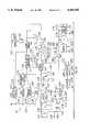
- FIG. 1is a block circuit diagram of the interrogator unit of the transponder arrangement according to the invention and of a base unit cooperating with the interrogator unit;
- FIG. 2ais a block circuit diagram of a first preferred embodiment responder unit
- FIG. 2bis a block circuit diagram of a second preferred embodiment responder unit.
- the transponder arrangement to be describedincludes an interrogator unit 10 as shown in FIG. 1, and a responder unit 12, as shown in FIG. 2.
- the interrogator unit 10is suitable for being held in the hand of an operator and is operable to transmit a RF interrogation pulse upon actuation of a key 14.
- This interrogator unit 10also has the capacity of receiving RF signals and detecting information contained in the signals.
- the RF signalscome from the responder unit 12 which replies to the transmission of a RF interrogation pulse by sending back a RF signal.
- a base unit 16(see FIG. 1) which is constructed as a stationary unit. The functions of the interrogator unit 10, the responder unit 12 and base unit 16 and their interaction will be described in more detail hereinafter. Firstly, the makeup of these units will be explained.
- the interrogator unit 10contains as central control unit a microprocessor 18 which is responsible for the control of the function sequences.
- a RF oscillator 20generates RF oscillations as soon as it has been set in operation by a signal at the output 22 of the microprocessor 18.
- the output signal of the RF oscillator 20can be supplied either via a switch 24 and an amplifier 26 or via a switch 28 and an amplifier 30 to a coupling coil 32.
- the switches 24 and 28are controlled by the microprocessor with the aid of signals emitted at its outputs 34 and 36 respectively.
- Coupled to the coupling coil 32is a coil 38 of a resonant circuit which consists of the coil 38 and the capacitor 40.
- a resistor 44In series with the coil 38 and the capacitor 40 is a resistor 44 bridgeable by a switch 42 and a further switch 46 lies between the resistor 44 and ground.
- the switches 42 and 46are controlled by the microprocessor which emits at its outputs 48 and 50 corresponding control signals.
- the switch 46When the switch 46 is closed the resonant circuit comprising the coil 38 and capacitor 40 acts as parallel resonant circuit whilst when the switch 46 is open it acts as series resonant circuit.
- the coil 38acts as transmitting and receiving coil which transmits the RF interrogation pulse supplied to it by the oscillator 20 and receives the RF signal sent back by the responder unit 12.
- the RF signals received by the resonant circuitare supplied to two amplifiers 52, 54 which are so designed that they amplify the RF signals received and limit them for pulse shaping. Connected to the amplifiers is a parallel resonant circuit 56 which ensures the necessary reception selectivity.
- the output of the amplifier 54is connected to a clock generator 58 which from the signal supplied thereto generates a clock signal and supplies the latter to the input 60 of the microprocessor 18.
- the output signal of the amplifier 54is supplied to a demodulator 62 which demodulates the signal applied thereto and supplies it to the input 64 of the microprocessor 18.
- the information contained in the received RF signalis supplied after the demodulation in the demodulator 62 via the microprocessor 18 to a random access memory 66 so that it can be stored in the latter.
- a bi-directional connection 68is disposed which makes it possible to enter information from the microprocessor 18 into the random access memory 66 and also to transfer information in the opposite direction.
- the information stored in the random access memory 66can be taken off at a jack 70.
- a display unit 72 fed by the microprocessor 18makes it possible for the operator to view the data contained in the received RF signal.
- a rechargeable battery 74is provided as a power supply.
- the output voltage of the battery 74is supplied after closing a switch 76 to the terminals designated by "+" of selected chips in the interrogator unit 10.
- the supply voltageis however supplied to the two amplifiers 52, 54, the clock generator 58 and the demodulator 62 via a separate switch 78 which is controlled by the microprocessor 18. This makes it possible for those circuit elements to be supplied with voltage and thus active only during a predetermined period of time within the total operating cycle.
- the battery 74can be charged by a voltage induced in a coil 80, rectified in a rectifier 82 and smoothed by means of a capacitor 84.
- the voltageis induced in coil 80 via a coil 112 in the base unit 16.
- a charge sensor 83detects when a charge voltage is induced in the coil 80, i.e. a charging operation of the battery 74 is taking place. It then emits to the input 88 of the microprocessor 18 a corresponding message signal.
- a further switch 90controlled by means of a signal from the output 92 of the microprocessor 18, can in the closed state supply the output signals of the RF oscillator 20 via an amplifier 94 to a coupling coil 9.
- the switch 90is typically used to activate the sending of a RF interrogation pulse to a responder unit 12 to initiate a data transfer to or from the responder unit 12.
- the carrier wave of the RF oscillator 20can be modulated.
- the modulation signal necessary for this purposeis supplied to the modulator 98 by the microprocessor 18 via a switch 100 which is controlled by means of a signal from the output 102 of the microprocessor.
- the modulation signal from the microprocessor 18is supplied when the switch 100 is closed also to a coupling coil 104.
- the base unit 16also illustrated in FIG. 1 is a stationary unit which is connected via a jack 106 to the mains supply network.
- a power supply 108the operating voltage for a charging voltage generator 110 is generated, the output signal of which is supplied to a coil 112.
- a switch 114is inserted between the power supply 108 and the charge voltage generator 110. The switch 114 is closed whenever the interrogator unit 10 is placed on the base unit 16. This is shown in FIG. 1 symbolically by a sort of actuating button 116 at the boundary line of the interrogator unit 10.
- the coils 112 and 80are arranged in the base unit and interrogator unit 10 spatially in such a manner that they cooperate like the primary winding and secondary winding of a transformer when the interrogator unit 10 is placed on the base unit 16. In this manner the battery 74 can be charged contactless as often as required.
- the coils 96 and 104 in the interrogator unit 10are so arranged that they are spatially very close to a coil 118 when the interrogator unit 10 is placed on the base unit 16. In this manner a contactless signal transmission between the coil 96 and the coil 104 on the one hand and the coil 118 on the other is possible.
- a demodulator 120serves to demodulate the signals coming from the coil 118.
- the first preferred embodiment responder unit 12 illustrated in FIGS. 2acontains for reception of the RF interrogation pulse a parallel resonant circuit 130 having a coil 132 and a capacitor 134. Connected to the parallel resonant circuit 130 is a capacitor 136 serving as energy accumulator. In addition the parallel resonant circuit 130 is connected to a RF bus 138.
- the resonant circuit 130typically acts as both receiver and transmitter as is well known in the art.
- the preferred embodiment in which a half-duplex communication mode is used for communication between the interrogator 10 and responder 12allows the single resonant circuit 130 to act as both receiver and transmitter operating at a single carrier frequency. In alternate embodiments of the present invention, separate circuits can be provide for receiver and transmitter.
- a full-duplex communication modeis used wherein the interrogator unit 10 sends a RF interrogation signal of a first frequency from its transmitter to the receiver of the responder unit 12 and the responder unit 12 sends a responsive RF signal of a second frequency from the responder unit transmitter to the receiver of the interrogator unit 10.
- a clock regenerator circuitreceives the RF signal from the RF bus 138 and regenerates a clock signal 139 having a substantially square waveform.
- An "end of burst detector" 142 connected to the RF bus 138has the function of monitoring the power level of a RF carrier at the RF bus 138.
- Such a RF carrieroccurs at the RF bus 138 whenever the parallel resonant circuit 130 receives a RF interrogation pulse from the interrogator unit 10.
- the "end of burst detector" 142emits at its output a RF threshold signal of predetermined value as soon as the power level of the RF carrier at the RF bus 138 drops below a predetermined threshold value.
- the RF carrieris rectified and as a result the capacitor 136 is charged.
- the energy stored in capacitor 136is proportional to the energy contained in the RF interrogation pulse.
- a zener diode function 146 connected to the capacitor 136ensures that the DC voltage which can be tapped off does not exceed a value defined by the zener voltage of the diode 146 in practical implementations such as within an integrated circuit, the zener diode function 146 might be accomplished by a number circuits well known in the art for limiting voltage.
- a zener diode function 146serves a similar function to prevent the voltage on the RF bus 138 from becoming too great. Initially upon interrogation of the responder unit 12 the interrogator unit 10 sends a RF signal to the responder unit for the express purpose of charging the responder unit 12.
- the charge phaseThis is referred to as the charge phase.
- the interrogator unit 10continues to provide an RF carrier for as long as is necessary to supply sufficient energy to the responder unit 12.
- the charge phaseends and the programming phase is initiated as soon as there is a brief (less than the Pre-Bit Time) lapse in the RF transmission. If the lapse in time is greater than the Pre-Bit Time, typically this means that no programming phase is initiated and the transponder arrangement is going directly from the charge phase to the read phase. Alternatively, another possible situation for the time lapse being greater than the Pre-Bit Time is when moving from the programming phase to the read phase.
- the carrier from the responder unitis modulated with data from the responder unit memory 168.
- a Power-On-Reset (POR, not shown) circuitprovides a POR signal to a start detect circuit 154.
- This POR circuitmonitors the Vcc level and is activated when the Vcc level rises from a level below a certain DC threshold to a level above a certain DC threshold.
- the POR signaloccurs within the charge phase of the responder unit 12.
- POR circuitsare well known in the art, indeed they are commonly used in almost all of the class of circuits known as "state machines" so that the circuits may be initialized to a known state.
- the start detect circuit 154upon receiving the POR signal will then monitor the output 150 of end of burst detection circuit 142. At output 150 an end of burst signal (EOB) is provided.
- EOBend of burst signal
- start detect circuit 154Upon receipt of an affirmatively stated EOB subsequent to the affirmatively stated Power-On-Reset signal, start detect circuit 154 switches power to the clock regenerator circuit 140 via switch 156. Output of start detect circuit 154 will remain positively asserted until a subsequent POR is received. All parts of the transponder other than the clock regenerator 140 are continuously supplied with Vcc, but preferably consume a negligible amount of power in their inactive states (i.e. when the clock regenerator 140 is inactive) due to the utilization of low power CMOS technology.
- a divider 158receives clock signal 139 and divides its frequency, preferably by a factor of eight.
- a pluck circuit 192preferably sends a momentary pulse each time it is so triggered by the divided clock signal as received from divider 158.
- This pluck circuit 192maintains the oscillation of resonant circuit 130 by momentarily rendering field-effect transistor or FET 190 conductive and forming therethrough a conductive path between the resonant circuit 130 and ground via RF bus 138 such that the resonant circuit gains electrical energy from storage capacitor 136.
- This pluck circuit 192is figuratively named to describe the maintaining of the oscillation of resonant circuit 130 much like the plucking of a guitar string maintains the oscillation of the guitar string. While this "plucking" action will momentarily lower the voltage on RF bus 138 the duration of the pulse is not sufficient given the channel resistance of FET 190 to lower the voltage below the threshold to trigger the end of burst detection circuit 142 to activate.
- a second divider 160divides the clock signal 139 again by a factor of two such that the clock frequency at the output of divider 160 is 1/16 the original clock frequency.
- Output shift register 172receives a parallel load from memory 168 or another source via data bus 220 upon receipt at its shift/load -- input 174 of a "load -- " signal from the output of start detect circuit 154. Subsequent to loading of the output shift register 172 the signal from start detect circuit 154 is asserted positively and hence a "shift" signal is received at the shift/load -- input 174 of register 172.
- the datarecirculates through the output shift register 172 via the data path 182 and also feeds the gate of FET or modulator 200 via data path 182.
- the output shift register dataare preferably low for a certain time (Pre-Bit-Time) and high or low dependent upon the data loaded therein.
- the Pre-Bit-Timeis used in this embodiment to allow the interrogator receiver coil 38 time to recover from power burst overload (Charge Phase) and it is used to discriminate the read function from the write function as will be described below.
- a low or "zero" signalis represented when the original resonant frequency of the resonant circuit 130 is maintained throughout a bit period.
- a high or "one” signalis represented when the new resonant frequency of the parallel combination of original resonant circuit 130 in parallel with capacitor 198 occurs within a bit period.
- a third divider 184receives at its input 186 the output of divider 160 and divides the clock signal by yet another factor of 128.
- the division factor of third divider 184is 128 in this instance due to the preferred data transmission bit length of 128. If this bit length were to change, then the division factor of third divider 184 would preferably change correspondingly.
- a diode 210maintains unidirectional current flow from the divider 184 into a parallel RC combination of a capacitor 212 and a resistor 214 which maintain charge on the gate of a field-effect transistor or FET 216 for a known duration.
- the capacitor 212may be charged by divider 184, but must be discharged through resistor 214.
- the FET 216serves to provide, when the gate of FET 216 maintained above a threshold voltage by the parallel combination of resistor 214 and capacitor 216, a low impedance discharge path for storage capacitor 136 to ground. In this manner, after transmission of a complete data frame in this case of 128 bits (read phase) from the transponder 12 to the interrogator unit 10, the remaining energy in the transponder 12 is eliminated by a short circuit across the charge capacitor 136. This action secures that the transponder is correctly initiated during the next charge phase and does not rest in a undefined or incorrect state such that a subsequent charge-up could be blocked. Additionally by this function, each transponder 12 within the field of the interrogator 10 has an identical start condition.
- the interrogator unit 10may pulse pause modulate (PPM) the RF transmission. This signal is reflected on RF bus 138.
- PPMpulse pause modulate
- a pulse pause modulation systemoperates by alternatively activating and deactivating a carrier wave.
- the "end of burst detector" 142senses a decrease in RF energy and is activated.
- the start detect circuit 154is then activated by the first EOB signal caused by the Start Bit.
- Start Bitis used in this preferred embodiment due to the fact that each data bit status is transmitted by the presence or absence of a carrier wave off phase as will be further described. Other embodiments are possible, however, in which no Start Bit needs to be transmitted.
- the duration of the time period in which the carrier is deactivated, known as the "off" phase,is shorter than the Pre-Bit-Time of the read phase. This particular requirement is used within this embodiment due to the fact that during the off phase, the output shift register 172 will start to shift. But since the Pre-Bit-Time is greater than the off phase the output shift register is unsuccessful in shifting anything but zeros out, so in fact FET 198 is never activated and inverted and no unwanted modulation of the carrier 138 will occur.
- the EOB signalis then deactivated when the carrier returns.
- the activations and deactivations of the EOB signalserve to provide a data stream to the data input 226 input of input shift register 228. Regardless of the transitions of EOB start detect circuit 154 maintains its output active until a new POR signal is received, thus maintaining power to clock regenerator circuit 140 via switch 156.
- a fourth divider 162is provided receive the clock signal from second divider 160 and the divide clock signal again by 16 in order to supply the clock input 227 of the input shift register 228 with an Input Clock signal.
- the write data rateis 1/256 of the resonant frequency or receive clock frequency. Provision must be made that the data is shifted into the input shift register 228 while the data is stable. This can be assured in the following manner.
- the fourth divider 162is activated by the start detect circuit 154 via AND gate 155. Each consecutive "zero" bit or "low” bit received by end of burst detection circuit 142 positively asserts the output 150 of the burst detection circuit. The positively asserted signal is then received the negative logic input of AND gate 155.
- the negative logic inputis indicated by a "bubble" at the input of AND gate 155 as is well known in the art.
- the output of AND gate 155will then be negatively asserted, thereby clearing the fourth divider 162 and synchronizing the Input Clock to the Input Data.
- End detection circuit 234detects the end of a data frame if a certain bit combination is in the input shift register 228 and thereupon activates the programming logic 232 if a programming command has been previously received by command decoder 230.
- the datais then transferred from input shift register 228 to memory 168 or another memory via parallel data bus 220.
- the memory the to which the data is transferredis an electrically-erasable programmable read only memory (EEPROM).
- end of burst detector 142is generally acting in the capacity of a pulse pause modulation (PPM) demodulator.
- PPMpulse pause modulation
- Test logic 236receives signals from command decoder 230 and data from data bus 220 and may initiate numerous test routines such as are commonly implemented in the field of logic circuit design. The results of these test routines may be placed on data bus 220 and output by shift register 172 to the modulation circuitry via field-effect transistor 200.
- a programmable tuning network 238is provided in the preferred embodiment of the present invention.
- This programmable tuning network 238operates by switching a network of parallel capacitors 240, each capacitor 240 being connected through a field-effect transistor or FET 242 to ground.
- Each field-effect transistoris connected to a latch 244 which receives and latches data from the memory 138 or from command decoder 230 via data bus 220 under control of a latch signal 243 from the command decoder 230.
- By switching a field-effect transistor 242 to a conducting "ON" stateits associated capacitor 240 is connected in parallel with parallel resonant circuit 130. This added capacitance will lower the resonant frequency of the parallel resonant circuit 130.
- a field-effect transistor 242By switching a field-effect transistor 242 to a non-conducting "OFF" state, its associated capacitor 240 is floating and has no effect on the parallel resonant circuit 130.
- a network 238 of FET/capacitor pairs 240,242can provide many different values of added capacitances depending on the combinations of each capacitor's 240 relative value as is well known in the art.
- latch 244could be a one-time-programmable (OTP) memory such that the data is fixedly stored therein and the device may be permanently programmed to set the value of programmable tuning network 238.
- command decoder 230interprets the sequence of bits received from input shift register 228 via data bus 220 as commands or data.
- the following information formatcould be used:
- the "X"'sindicate data positions which may be filled by logical 0's and 1's.
- the number of bits in each groupare, of course, merely exemplary. The format of this information sequence would be determined by the needs of the particular application. Indeed, upon examination of this specification, other orderings of the groups of information would be readily apparent to one of ordinary skill in the art. It is therefore intended that the appended claims encompass any such modifications or embodiments.
- the first group of bitsare the Start Signal or Start bits. These bits would preferably be followed by a Group Address which the command decoder 230 might compare to an address stored in responder unit memory 168.
- a formatcould be sent by the interrogator unit such as all zeros in the Group Address indicating the responder unit command decoder 230 should compare the following Unit Address to another address stored in memory 168. Should Group Addressing be desired, however, interrogator unit 10 might send a Group Address followed by all zeros in the Unit Address portion of the sequence to so indicate. Alternatively, the Group Addressing might even be used in conjunction with the Unit Addressing.
- the address sequencemight be followed by a Command which could be used to indicate the next action desired from the responder unit 12. The command might then be followed by Data on which the responder unit 12 might operate.
- the addresses stored within responder unit memory 168 for comparison to Group and/or Unit Addresses within the data sequencemight be updated.
- a Stop Signal or Stop bitsmight follow to indicate the end of the information transmission from interrogator unit 10.
- the interrogator unit 10might send a RF interrogation pulse directed to a particular Group Address and a number of responder units 12 within communication range of the interrogator unit 10 will have addresses corresponding to this Group Address. In this instance, all the responder units 12 would respond to the RF interrogation pulse, causing the interrogator unit 10, in all likelihood, to receive an unintelligible response.
- An example of an unintelligible responsemight be when the interrogator unit 10 expects a stream of data in a certain format (i.e. an alternating sequence of 0's and 1's) and that format is not detected, then it is likely that a number of responder units are simultaneously transmitting.
- the interrogator unit 10might be satisfied to know that a number of responder units 12 are present within its communication range.
- the interrogator unit 10might either modify its transmission strength in an attempt to physically isolate a single responder unit, or the interrogator unit might begin to poll the responder units 12 by their Unit Addresses.
- the factors of the dividers disclosed in the embodiments listed hereinare chosen to fit the particulars of each design.
- the division factorsshould be computed in each case to most optimally perform the task for which they were designed.
- the second preferred embodiment responder unit 12a shown in FIG. 2bis substantially similar to the first preferred embodiment responder unit 12 which was shown in FIG. 2a.
- the general functions and the read functions for the second preferred embodiment responder unit 12ais preferably the same as that described above for first preferred embodiment responder unit 12.
- the write functionwill differ slightly from that described hereinabove with respect to the first preferred embodiment responder unit 12.
- an "end of burst detector” 142is connected to the RF bus 138 and has the function of monitoring the power level of a RF carrier at the RF bus 138. Such a RF carrier occurs at the RF bus 138 whenever the parallel resonant circuit 130 receives a RF interrogation pulse from the interrogator unit 10.
- the "end of burst detector” 142emits at its output a RF threshold signal of predetermined value as soon as the power level of the RF carrier at the RF bus 138 drops below a predetermined threshold value.
- Second preferred embodiment responder unit 12adiffers in that it determines whether a received data bit is a "zero" or a "one" bit by the duration of the time period for which the RF carrier is deactivated (i.e. Pulse Width Modulation, PWM). For example, if the duration for which the carrier is deactivated is less than six clock cycles, the data could be defined as “zero” or “low”. If the duration for which the carrier is deactivated is greater than six clock cycles, the data could be defined as "one” or "high”. Obviously the bit definitions could be reversed. A start bit circuit 154 which would generate a start bit as in the first preferred embodiment could be used. However, since every data bit comprises some kind of signal transition and the actual data status is dependent on the duration of the signal transition, a Start Bit is no longer necessary.
- PWMPulse Width Modulation
- the output 150 of RF threshold detection circuit 142is used in this embodiment as an Input Clock signal for input shift register 228. Assuming the input shift register 228 uses the rising edge of the Input Clock and assuming that RF threshold detection circuit 142 provides a "high" signal during the time periods during which the carrier is deactivated, the output 150 of RF threshold detection circuit 142 is inverted by an inverter 216 before being received by the input shift register 228. This assures that the data received at the input shift register 228 is valid when it is latched by the Input Clock signal.
- the Input Data received at the data input 226 of the input shift register 228is provided by a divide-by-six divider 162a which operates in a different function than the divider 162 provided in the first preferred embodiment.
- Divider 162acounts the clock transitions of a clock signal having 1/16 the resonant frequency as it is output from divider 160.
- Divider 162areceives at its enable/clear -- input the output 150 of RF threshold detector 142. Normally this input will be held low such that the divider remains in its cleared state.
- a "high" signal from "end of burst detector” 142enables the divider 162a to begin counting clock transitions.
- the length of the pulseis defined to be less than six clock cycles such that the divider 162a never reaches its maximum count and hence never is asserted “high”.
- EOB through inverter 216acts to load a "zero" into input shift register 226. If however, the length of the pulse is defined to be greater than six cycles for a "one" signal, then the divider 162a does reach its maximum count and asserts its output “high”. Thus upon transition of the Input Clock 227 to the input shift register 228 a "one" is loaded therein via the Input Data 226 signal.
- the end detection circuit 234counts the number of input clocks to activate the programming logic 232 if a correct data frame is received and the command decoder 230 has detected a subsequent programming command.
- the datais then transferred from input shift register 228 to memory 168 or another memory via parallel data bus 220.
- the memory to which the data is transferredis an electrically-erasable programmable read only memory (EEPROM).
- responder unit 12,12aIn practical use, numerous objects, each provided with a responder unit 12,12a, are addressed in succession by the interrogator unit 10 by transmission of a RF interrogation pulse.
- the information returned by the responder units 12,12ais received by the interrogator unit 10 and stored in the random access memory 66.
- the responder units 12,12awhich are within the transmitting range of the interrogator unit 10 are addressed. It may, however, also be desirable to address amongst a larger number of responder units 12,12a only quite specific individual units and cause them to return the information stored in them. This can be achieved by providing the processor 202 in the responder unit 12,12a.
- the RF interrogation pulse to be transmittedis modulated with the address which is provided for the responder unit 12,12a to be specifically activated.
- the processorpreferably monitors the data received by input shift register 228 and placed upon data bus 220, then determines whether the address applied to it coincides with an address fixedly or temporarily set in the responder unit 12,12a. If the processor 202 detects such coincidence, it furnishes at its output 206 a start signal which instead of the start signal furnished by the start detect circuit 154 in the use previously described, allows the sending back to the interrogator unit 10 the information contained in the memory 168 by enabling the clock regeneration circuit 140. In this manner, amongst a large number of objects provided with responder units 12,12a it is possible to specifically search for and find those with specific addresses.
- the responder unit 12,12athe energy contained in the received RF carrier wave is stored and utilized for supplying assemblies necessary for the transmitting back of the stored data.
- the clock signals necessary for the control and synchronizationare derived from the RF carrier wave which is generated immediately after termination of the RF interrogation pulse in the responder unit 12,12a. Due to the derivation of the clock signal from the RF carrier wave signal a very good synchronization is achieved between the transmitter side and receiving side. The arrangement is not sensitive to frequency changes and calibration is therefore not necessary.
- the responder unit 12,12a describedcan be made almost completely as an integrated circuit so that it can be produced with very small dimensions. Only the coil 132, the capacitor 134 and the capacitor 136 need be provided as individual components outside the integrated circuit.
- a responder unit 12,12a with this constructioncould, for example, be disposed in each individual spare part of a large store of spare parts from which individual spares are automatically picked when required. Using an interrogator unit 10 the spares of a desired type or characteristic could be specifically sought in the store and then automatically removed.
- the responder 12,12acan for example also be attached to animals in a large herd and employing the interrogator unit 10 the animals can be continuously supervised and checked. Since the components of the responder unit 12,12a can be made very small it is even possible to make the entire unit in the form of a small pin which can be implanted under the skin of the animal. A corresponding construction is shown in FIG. 7.
- the coil in this examplecould be wound round a small ferrite core 220 which increases the sensitivity.
- the datais modulated onto the responder unit carrier wave by use of a FET 200 which can connect a capacitance in parallel with the resonant circuit 130.
- a FET 200which can connect a capacitance in parallel with the resonant circuit 130.
- Many other modulators 200can be envisioned which could modulate carrier waves generated using any of a number of possible carrier wave generators.
- display devicescan be cathode ray tubes or other raster-scanned devices, liquid crystal displays, or plasma displays.
- Microcomputerin some contexts is used to mean that microcomputer requires a memory and "microprocessor” does not. The usage herein is that these terms can also be synonymous and refer to equivalent things.
- processing circuitryor “control circuitry” comprehends ASICs (application specific integrated circuits), PAL (programmable array logic), PLAs (programmable logic arrays), decoders, memories, non-software based processors, or other circuitry, or digital computers including microprocessors and microcomputers of any architecture, or combinations thereof.
- Memory devicesinclude SRAM (static random access memory), DRAM (dynamic random access memory), pseudo-static RAM, latches, EEPROM (electrically-erasable programmable read-only memory), EPROM (erasable programmable read-only memory), registers, or any other memory device known in the art. Words of inclusion are to be interpreted as nonexhaustive in considering the scope of the invention.
- Frequency shift keying (FSK) modulationis envisioned as a possible data modulation scheme, as well as pulse-pause modulation, amplitude shift keying (ASK), quadrature AM (QAM) modulation, quadrature phase shift keying (QPSK), or any other modulation.
- FSKFrequency shift keying
- ASKamplitude shift keying
- QAMquadrature AM
- QPSKquadrature phase shift keying
- Different types of multiplexingsuch as time or frequency modulation might be effected to avoid cross-signal interference.
- Discrete components or fully integrated circuits in silicon (Si), gallium arsenide (GaAs), or other electronic materials families, as well as in optical-based or other technology-based forms and embodimentsmight be used to implement the circuits described herein. It should be understood that various embodiments of the invention can employ or be embodied in hardware, software or microcoded firmware.
Landscapes
- Engineering & Computer Science (AREA)
- Radar, Positioning & Navigation (AREA)
- Remote Sensing (AREA)
- Computer Networks & Wireless Communication (AREA)
- Physics & Mathematics (AREA)
- General Physics & Mathematics (AREA)
- Signal Processing (AREA)
- Spectroscopy & Molecular Physics (AREA)
- Radar Systems Or Details Thereof (AREA)
Abstract
Description
______________________________________ Pat No./Pat Appl No. Filing Date TI Case No. ______________________________________ 5,053,774 2/13/91 TI-12797A 07,981,635 11/25/92 TI-16688 ______________________________________
__________________________________________________________________________Start Group Address Unit Address Command Data Stop __________________________________________________________________________XXX . . . X XXX . . . XXX XXX . . . XXX XXX . . . XX XXX . . . X XXXX __________________________________________________________________________
Claims (11)
Priority Applications (1)
| Application Number | Priority Date | Filing Date | Title |
|---|---|---|---|
| US07/986,950US5410315A (en) | 1992-12-08 | 1992-12-08 | Group-addressable transponder arrangement |
Applications Claiming Priority (1)
| Application Number | Priority Date | Filing Date | Title |
|---|---|---|---|
| US07/986,950US5410315A (en) | 1992-12-08 | 1992-12-08 | Group-addressable transponder arrangement |
Publications (1)
| Publication Number | Publication Date |
|---|---|
| US5410315Atrue US5410315A (en) | 1995-04-25 |
Family
ID=25532922
Family Applications (1)
| Application Number | Title | Priority Date | Filing Date |
|---|---|---|---|
| US07/986,950Expired - Fee RelatedUS5410315A (en) | 1992-12-08 | 1992-12-08 | Group-addressable transponder arrangement |
Country Status (1)
| Country | Link |
|---|---|
| US (1) | US5410315A (en) |
Cited By (122)
| Publication number | Priority date | Publication date | Assignee | Title |
|---|---|---|---|---|
| US5491484A (en)* | 1992-12-15 | 1996-02-13 | Texas Instruments Incorporated | Electronic transponder tuning circuitry |
| US5504485A (en)* | 1994-07-21 | 1996-04-02 | Amtech Corporation | System for preventing reading of undesired RF signals |
| US5508705A (en)* | 1994-01-10 | 1996-04-16 | Spiess; Newton E. | Vehicle identification classification and communication system |
| US5515053A (en)* | 1993-11-04 | 1996-05-07 | Licentia Patent-Verwaltlungs-Gmbh | Transponder and data communications system |
| US5550536A (en)* | 1994-08-17 | 1996-08-27 | Texas Instruments Deutschland Gmbh | Circuit frequency following technique transponder resonant |
| US5550547A (en)* | 1994-09-12 | 1996-08-27 | International Business Machines Corporation | Multiple item radio frequency tag identification protocol |
| US5621396A (en)* | 1994-06-30 | 1997-04-15 | Texas Instruments Incorporated | Method and apparatus with adaptive transponder plucking |
| US5648765A (en)* | 1995-03-08 | 1997-07-15 | Cresap; Michael S. | Tag tansponder system and method to identify items for purposes such as locating, identifying, counting, inventorying, or the like |
| US5673037A (en)* | 1994-09-09 | 1997-09-30 | International Business Machines Corporation | System and method for radio frequency tag group select |
| US5721535A (en)* | 1904-05-27 | 1998-02-24 | Rohm Co., Ltd. | Tag responsive to high frequency for varying capacitance of capacitor in power source |
| US5745049A (en)* | 1995-07-20 | 1998-04-28 | Yokogawa Electric Corporation | Wireless equipment diagnosis system |
| US5777561A (en)* | 1996-09-30 | 1998-07-07 | International Business Machines Corporation | Method of grouping RF transponders |
| US5793324A (en)* | 1996-01-19 | 1998-08-11 | Texas Instruments Incorporated | Transponder signal collision avoidance system |
| US5808797A (en) | 1992-04-28 | 1998-09-15 | Silicon Light Machines | Method and apparatus for modulating a light beam |
| US5828318A (en)* | 1996-05-08 | 1998-10-27 | International Business Machines Corporation | System and method for selecting a subset of autonomous and independent slave entities |
| US5841579A (en) | 1995-06-07 | 1998-11-24 | Silicon Light Machines | Flat diffraction grating light valve |
| US5942987A (en)* | 1994-09-09 | 1999-08-24 | Intermec Ip Corp. | Radio frequency identification system with write broadcast capability |
| US5982553A (en) | 1997-03-20 | 1999-11-09 | Silicon Light Machines | Display device incorporating one-dimensional grating light-valve array |
| US6002344A (en)* | 1997-11-21 | 1999-12-14 | Bandy; William R. | System and method for electronic inventory |
| US6046683A (en)* | 1996-12-31 | 2000-04-04 | Lucent Technologies Inc. | Modulated backscatter location system |
| US6088102A (en) | 1997-10-31 | 2000-07-11 | Silicon Light Machines | Display apparatus including grating light-valve array and interferometric optical system |
| US6101036A (en) | 1998-06-23 | 2000-08-08 | Silicon Light Machines | Embossed diffraction grating alone and in combination with changeable image display |
| US6130770A (en) | 1998-06-23 | 2000-10-10 | Silicon Light Machines | Electron gun activated grating light valve |
| US6167236A (en)* | 1996-01-31 | 2000-12-26 | Texas Instruments Deutschland, Gmbh | Damping modulation circuit for a full-duplex transponder |
| US6215579B1 (en) | 1998-06-24 | 2001-04-10 | Silicon Light Machines | Method and apparatus for modulating an incident light beam for forming a two-dimensional image |
| US6249212B1 (en)* | 1994-10-05 | 2001-06-19 | Avid Marketing, Inc. | Universal electronic identification tag |
| US6271808B1 (en) | 1998-06-05 | 2001-08-07 | Silicon Light Machines | Stereo head mounted display using a single display device |
| US6362737B1 (en) | 1998-06-02 | 2002-03-26 | Rf Code, Inc. | Object Identification system with adaptive transceivers and methods of operation |
| US6369710B1 (en) | 2000-03-27 | 2002-04-09 | Lucent Technologies Inc. | Wireless security system |
| US6448903B1 (en)* | 1996-05-27 | 2002-09-10 | The Yokohama Rubber Co., Ltd. | Device for detecting internal pressure of air-filled gunwale protector |
| US6456668B1 (en) | 1996-12-31 | 2002-09-24 | Lucent Technologies Inc. | QPSK modulated backscatter system |
| US20020149480A1 (en)* | 2001-02-12 | 2002-10-17 | Matrics, Inc. | Method, system, and apparatus for remote data calibration of a RFID tag population |
| US6472975B1 (en)* | 1994-06-20 | 2002-10-29 | Avid Marketing, Inc. | Electronic identification system with improved sensitivity |
| US6486769B1 (en) | 1999-12-22 | 2002-11-26 | Intermec Ip Corp. | Method and system for automatic adjustment and diagnosis of radio frequency identification systems using programmable checktags |
| US20020183882A1 (en)* | 2000-10-20 | 2002-12-05 | Michael Dearing | RF point of sale and delivery method and system using communication with remote computer and having features to read a large number of RF tags |
| US20030117281A1 (en)* | 2001-12-21 | 2003-06-26 | Timur Sriharto | Dynamic control containment unit |
| US20030214389A1 (en)* | 2002-04-01 | 2003-11-20 | Matrics, Inc. | Method and system for optimizing an interrogation of a tag population |
| US20040046642A1 (en)* | 2002-09-05 | 2004-03-11 | Honeywell International Inc. | Protocol for addressing groups of RFID tags |
| US6707591B2 (en) | 2001-04-10 | 2004-03-16 | Silicon Light Machines | Angled illumination for a single order light modulator based projection system |
| US6712480B1 (en) | 2002-09-27 | 2004-03-30 | Silicon Light Machines | Controlled curvature of stressed micro-structures |
| US6728023B1 (en) | 2002-05-28 | 2004-04-27 | Silicon Light Machines | Optical device arrays with optimized image resolution |
| US6747781B2 (en) | 2001-06-25 | 2004-06-08 | Silicon Light Machines, Inc. | Method, apparatus, and diffuser for reducing laser speckle |
| US20040111338A1 (en)* | 1997-11-21 | 2004-06-10 | Matrics, Inc. | System and method for electronic inventory |
| US20040134984A1 (en)* | 2002-10-25 | 2004-07-15 | Powell Kevin J. | Optimization of a binary tree traversal with secure communications |
| US6764875B2 (en) | 1998-07-29 | 2004-07-20 | Silicon Light Machines | Method of and apparatus for sealing an hermetic lid to a semiconductor die |
| US6767751B2 (en) | 2002-05-28 | 2004-07-27 | Silicon Light Machines, Inc. | Integrated driver process flow |
| US6782205B2 (en) | 2001-06-25 | 2004-08-24 | Silicon Light Machines | Method and apparatus for dynamic equalization in wavelength division multiplexing |
| US20040178264A1 (en)* | 2000-10-20 | 2004-09-16 | Promega Corporation | Radio frequency identification method and system of distributing products |
| US20040185806A1 (en)* | 2001-05-03 | 2004-09-23 | Hendrik Van Zyl Smit | Communication between a transponder and an interrogator |
| US6800238B1 (en) | 2002-01-15 | 2004-10-05 | Silicon Light Machines, Inc. | Method for domain patterning in low coercive field ferroelectrics |
| US6801354B1 (en) | 2002-08-20 | 2004-10-05 | Silicon Light Machines, Inc. | 2-D diffraction grating for substantially eliminating polarization dependent losses |
| US6806997B1 (en) | 2003-02-28 | 2004-10-19 | Silicon Light Machines, Inc. | Patterned diffractive light modulator ribbon for PDL reduction |
| US6813059B2 (en) | 2002-06-28 | 2004-11-02 | Silicon Light Machines, Inc. | Reduced formation of asperities in contact micro-structures |
| US6812852B1 (en) | 1994-09-09 | 2004-11-02 | Intermac Ip Corp. | System and method for selecting a subset of autonomous and independent slave entities |
| US6822797B1 (en) | 2002-05-31 | 2004-11-23 | Silicon Light Machines, Inc. | Light modulator structure for producing high-contrast operation using zero-order light |
| US6825766B2 (en) | 2001-12-21 | 2004-11-30 | Genei Industries, Inc. | Industrial data capture system including a choke point portal and tracking software for radio frequency identification of cargo |
| US6829077B1 (en) | 2003-02-28 | 2004-12-07 | Silicon Light Machines, Inc. | Diffractive light modulator with dynamically rotatable diffraction plane |
| US6829092B2 (en) | 2001-08-15 | 2004-12-07 | Silicon Light Machines, Inc. | Blazed grating light valve |
| US6829258B1 (en) | 2002-06-26 | 2004-12-07 | Silicon Light Machines, Inc. | Rapidly tunable external cavity laser |
| US6865346B1 (en) | 2001-06-05 | 2005-03-08 | Silicon Light Machines Corporation | Fiber optic transceiver |
| US6872984B1 (en) | 1998-07-29 | 2005-03-29 | Silicon Light Machines Corporation | Method of sealing a hermetic lid to a semiconductor die at an angle |
| US6876294B1 (en) | 1998-08-18 | 2005-04-05 | Identec Limited | Transponder identification system |
| US20050088286A1 (en)* | 1994-09-09 | 2005-04-28 | Heinrich Harley K. | Radio frequency identification system with write broadcast capability |
| US20050099268A1 (en)* | 2003-11-12 | 2005-05-12 | Ari Juels | Radio frequency identification system with privacy policy implementation based on device classification |
| US20050114326A1 (en)* | 2003-11-07 | 2005-05-26 | Smith John S. | Methods and apparatuses to identify devices |
| US20050121526A1 (en)* | 2003-12-09 | 2005-06-09 | Intelleflex Corporation | Battery activation circuit |
| US6908201B2 (en) | 2002-06-28 | 2005-06-21 | Silicon Light Machines Corporation | Micro-support structures |
| US6922272B1 (en) | 2003-02-14 | 2005-07-26 | Silicon Light Machines Corporation | Method and apparatus for leveling thermal stress variations in multi-layer MEMS devices |
| US6922273B1 (en) | 2003-02-28 | 2005-07-26 | Silicon Light Machines Corporation | PDL mitigation structure for diffractive MEMS and gratings |
| US6927891B1 (en) | 2002-12-23 | 2005-08-09 | Silicon Light Machines Corporation | Tilt-able grating plane for improved crosstalk in 1×N blaze switches |
| US6928207B1 (en) | 2002-12-12 | 2005-08-09 | Silicon Light Machines Corporation | Apparatus for selectively blocking WDM channels |
| US6934070B1 (en) | 2002-12-18 | 2005-08-23 | Silicon Light Machines Corporation | Chirped optical MEM device |
| US6947613B1 (en) | 2003-02-11 | 2005-09-20 | Silicon Light Machines Corporation | Wavelength selective switch and equalizer |
| US6956878B1 (en) | 2000-02-07 | 2005-10-18 | Silicon Light Machines Corporation | Method and apparatus for reducing laser speckle using polarization averaging |
| US6956995B1 (en) | 2001-11-09 | 2005-10-18 | Silicon Light Machines Corporation | Optical communication arrangement |
| US20050242196A1 (en)* | 2001-05-31 | 2005-11-03 | Alien Technology Corp. | Integrated circuits with persistent data storage |
| US20050263591A1 (en)* | 2003-08-09 | 2005-12-01 | Smith John S | Methods and apparatuses to identify devices |
| US6987600B1 (en) | 2002-12-17 | 2006-01-17 | Silicon Light Machines Corporation | Arbitrary phase profile for better equalization in dynamic gain equalizer |
| US6991953B1 (en) | 2001-09-13 | 2006-01-31 | Silicon Light Machines Corporation | Microelectronic mechanical system and methods |
| US7027202B1 (en) | 2003-02-28 | 2006-04-11 | Silicon Light Machines Corp | Silicon substrate as a light modulator sacrificial layer |
| US20060093312A1 (en)* | 2004-10-30 | 2006-05-04 | Samsung Electro-Mechanics Co., Ltd. | Content playback system and method |
| US7042611B1 (en) | 2003-03-03 | 2006-05-09 | Silicon Light Machines Corporation | Pre-deflected bias ribbons |
| US7054515B1 (en) | 2002-05-30 | 2006-05-30 | Silicon Light Machines Corporation | Diffractive light modulator-based dynamic equalizer with integrated spectral monitor |
| US20060113302A1 (en)* | 2004-09-09 | 2006-06-01 | Inteligistics, Inc. | Modular shipping unit and system |
| US7057819B1 (en) | 2002-12-17 | 2006-06-06 | Silicon Light Machines Corporation | High contrast tilting ribbon blazed grating |
| US7057795B2 (en) | 2002-08-20 | 2006-06-06 | Silicon Light Machines Corporation | Micro-structures with individually addressable ribbon pairs |
| US7068372B1 (en) | 2003-01-28 | 2006-06-27 | Silicon Light Machines Corporation | MEMS interferometer-based reconfigurable optical add-and-drop multiplexor |
| WO2006086518A2 (en) | 2005-02-09 | 2006-08-17 | Tc License Ltd. | Rf tag system with single step read and write commands |
| US20060192652A1 (en)* | 2005-02-14 | 2006-08-31 | Inteligistics, Inc. | Identification system |
| US20060255131A1 (en)* | 2005-05-11 | 2006-11-16 | Intelleflex Corporation | Smart tag activation |
| US20060261950A1 (en)* | 2005-03-29 | 2006-11-23 | Symbol Technologies, Inc. | Smart radio frequency identification (RFID) items |
| US20060289650A1 (en)* | 2005-06-27 | 2006-12-28 | Mobile Aspects, Inc. | Networked monitoring system |
| US20070013484A1 (en)* | 2001-10-09 | 2007-01-18 | Curt Carrender | Methods and apparatuses for identification |
| US20070018794A1 (en)* | 2005-07-20 | 2007-01-25 | Intelleflex Corporation | Selective RF device activation |
| US7177081B2 (en) | 2001-03-08 | 2007-02-13 | Silicon Light Machines Corporation | High contrast grating light valve type device |
| US20070103273A1 (en)* | 2005-11-09 | 2007-05-10 | Feller Walter J | Short-distance ranging system |
| US7286764B1 (en) | 2003-02-03 | 2007-10-23 | Silicon Light Machines Corporation | Reconfigurable modulator-based optical add-and-drop multiplexer |
| US20070262851A1 (en)* | 2001-05-31 | 2007-11-15 | Stewart Roger G | Methods and apparatuses to identify devices |
| US7377445B1 (en) | 2001-05-31 | 2008-05-27 | Alien Technology Corporation | Integrated circuits with persistent data storage |
| US7391973B1 (en) | 2003-02-28 | 2008-06-24 | Silicon Light Machines Corporation | Two-stage gain equalizer |
| US7427912B1 (en) | 1998-01-08 | 2008-09-23 | Intermec Ip Corp. | Method and system for storage and recovery of vital information on radio frequency transponders |
| US7511621B1 (en) | 1995-08-31 | 2009-03-31 | Intermec Ip Corp. | High-performance mobile power antennas |
| US7571139B1 (en) | 1999-02-19 | 2009-08-04 | Giordano Joseph A | System and method for processing financial transactions |
| US20090195362A1 (en)* | 2005-05-02 | 2009-08-06 | Mozafari Mehdi G | Rfid system and method to monitor a set of objects |
| US7710275B2 (en) | 2007-03-16 | 2010-05-04 | Promega Corporation | RFID reader enclosure and man-o-war RFID reader system |
| US20100191049A1 (en)* | 2008-10-28 | 2010-07-29 | Mobile Aspects, Inc. | Endoscope Storage Cabinet, Tracking System, and Signal Emitting Member |
| US7844505B1 (en) | 1997-11-21 | 2010-11-30 | Symbol Technologies, Inc. | Automated real-time distributed tag reader network |
| US20110050400A1 (en)* | 2009-08-25 | 2011-03-03 | Sensormatic Electronics Corporation | Rfid portal system with rfid tags having various read ranges |
| US20110148599A1 (en)* | 2009-12-21 | 2011-06-23 | Electronics And Telecommunications Research Institute | Rfid reader, rfid tag, and method of recognizing plurality of rfid tags |
| US8314688B2 (en) | 2007-08-22 | 2012-11-20 | Tagarray, Inc. | Method and apparatus for low power modulation and massive medium access control |
| GB2494890A (en)* | 2011-09-21 | 2013-03-27 | Friendly Technologies Ltd | Listing transponders |
| US8538801B2 (en) | 1999-02-19 | 2013-09-17 | Exxonmobile Research & Engineering Company | System and method for processing financial transactions |
| US8548098B2 (en) | 2005-12-15 | 2013-10-01 | Intelleflex Corporation | Clock-free activation circuit |
| US8648699B2 (en) | 2010-07-19 | 2014-02-11 | Mobile Aspects, Inc. | Item tracking system and arrangement |
| US20150180608A1 (en)* | 2013-12-20 | 2015-06-25 | Nxp B.V. | End of communication detection |
| US9224124B2 (en) | 2013-10-29 | 2015-12-29 | Mobile Aspects, Inc. | Item storage and tracking cabinet and arrangement |
| US9348013B2 (en) | 2013-09-18 | 2016-05-24 | Mobile Aspects, Inc. | Item hanger arrangement, system, and method |
| US20160300083A1 (en)* | 2015-04-10 | 2016-10-13 | Socionext Inc. | Integrated circuit, diagnostic system and diagnostic method |
| US9729363B2 (en) | 2013-09-09 | 2017-08-08 | Crfs Limited | Frequency discriminator |
| US9892618B2 (en) | 2013-08-09 | 2018-02-13 | Mobile Aspects, Inc. | Signal emitting member attachment system and arrangement |
| US10034400B2 (en) | 2013-12-04 | 2018-07-24 | Mobile Aspects, Inc. | Item storage arrangement system and method |
| USRE47599E1 (en) | 2000-10-20 | 2019-09-10 | Promega Corporation | RF point of sale and delivery method and system using communication with remote computer and having features to read a large number of RF tags |
Citations (12)
| Publication number | Priority date | Publication date | Assignee | Title |
|---|---|---|---|---|
| US3713148A (en)* | 1970-05-21 | 1973-01-23 | Communications Services Corp I | Transponder apparatus and system |
| US4131881A (en)* | 1977-09-12 | 1978-12-26 | Robinson Paul B | Communication system including addressing apparatus for use in remotely controllable devices |
| US4364043A (en)* | 1979-05-30 | 1982-12-14 | The University Of Adelaide | Efficient object identification system |
| US4370653A (en)* | 1980-07-21 | 1983-01-25 | Rca Corporation | Phase comparator system |
| US4912471A (en)* | 1983-11-03 | 1990-03-27 | Mitron Systems Corporation | Interrogator-responder communication system |
| US4979170A (en)* | 1988-01-19 | 1990-12-18 | Qualcomm, Inc. | Alternating sequential half duplex communication system |
| US4983976A (en)* | 1988-06-17 | 1991-01-08 | Omron Tateisi Electronics Co. | Signal transmission system and method |
| US5053774A (en)* | 1987-07-31 | 1991-10-01 | Texas Instruments Deutschland Gmbh | Transponder arrangement |
| US5124699A (en)* | 1989-06-30 | 1992-06-23 | N.V. Netherlandsche Apparatenfabriek Nedap | Electromagnetic identification system for identifying a plurality of coded responders simultaneously present in an interrogation field |
| US5144314A (en)* | 1987-10-23 | 1992-09-01 | Allen-Bradley Company, Inc. | Programmable object identification transponder system |
| US5268668A (en)* | 1992-01-07 | 1993-12-07 | Detection Systems, Inc. | Security/fire alarm system with group-addressing remote sensors |
| US5351052A (en)* | 1992-09-28 | 1994-09-27 | Texas Instruments Incorporated | Transponder systems for automatic identification purposes |
- 1992
- 1992-12-08USUS07/986,950patent/US5410315A/ennot_activeExpired - Fee Related
Patent Citations (12)
| Publication number | Priority date | Publication date | Assignee | Title |
|---|---|---|---|---|
| US3713148A (en)* | 1970-05-21 | 1973-01-23 | Communications Services Corp I | Transponder apparatus and system |
| US4131881A (en)* | 1977-09-12 | 1978-12-26 | Robinson Paul B | Communication system including addressing apparatus for use in remotely controllable devices |
| US4364043A (en)* | 1979-05-30 | 1982-12-14 | The University Of Adelaide | Efficient object identification system |
| US4370653A (en)* | 1980-07-21 | 1983-01-25 | Rca Corporation | Phase comparator system |
| US4912471A (en)* | 1983-11-03 | 1990-03-27 | Mitron Systems Corporation | Interrogator-responder communication system |
| US5053774A (en)* | 1987-07-31 | 1991-10-01 | Texas Instruments Deutschland Gmbh | Transponder arrangement |
| US5144314A (en)* | 1987-10-23 | 1992-09-01 | Allen-Bradley Company, Inc. | Programmable object identification transponder system |
| US4979170A (en)* | 1988-01-19 | 1990-12-18 | Qualcomm, Inc. | Alternating sequential half duplex communication system |
| US4983976A (en)* | 1988-06-17 | 1991-01-08 | Omron Tateisi Electronics Co. | Signal transmission system and method |
| US5124699A (en)* | 1989-06-30 | 1992-06-23 | N.V. Netherlandsche Apparatenfabriek Nedap | Electromagnetic identification system for identifying a plurality of coded responders simultaneously present in an interrogation field |
| US5268668A (en)* | 1992-01-07 | 1993-12-07 | Detection Systems, Inc. | Security/fire alarm system with group-addressing remote sensors |
| US5351052A (en)* | 1992-09-28 | 1994-09-27 | Texas Instruments Incorporated | Transponder systems for automatic identification purposes |
Cited By (217)
| Publication number | Priority date | Publication date | Assignee | Title |
|---|---|---|---|---|
| US5721535A (en)* | 1904-05-27 | 1998-02-24 | Rohm Co., Ltd. | Tag responsive to high frequency for varying capacitance of capacitor in power source |
| US5808797A (en) | 1992-04-28 | 1998-09-15 | Silicon Light Machines | Method and apparatus for modulating a light beam |
| US5491484A (en)* | 1992-12-15 | 1996-02-13 | Texas Instruments Incorporated | Electronic transponder tuning circuitry |
| US5515053A (en)* | 1993-11-04 | 1996-05-07 | Licentia Patent-Verwaltlungs-Gmbh | Transponder and data communications system |
| US5508705A (en)* | 1994-01-10 | 1996-04-16 | Spiess; Newton E. | Vehicle identification classification and communication system |
| US6472975B1 (en)* | 1994-06-20 | 2002-10-29 | Avid Marketing, Inc. | Electronic identification system with improved sensitivity |
| US5621396A (en)* | 1994-06-30 | 1997-04-15 | Texas Instruments Incorporated | Method and apparatus with adaptive transponder plucking |
| US5504485A (en)* | 1994-07-21 | 1996-04-02 | Amtech Corporation | System for preventing reading of undesired RF signals |
| US5550536A (en)* | 1994-08-17 | 1996-08-27 | Texas Instruments Deutschland Gmbh | Circuit frequency following technique transponder resonant |
| US5942987A (en)* | 1994-09-09 | 1999-08-24 | Intermec Ip Corp. | Radio frequency identification system with write broadcast capability |
| US7616094B2 (en) | 1994-09-09 | 2009-11-10 | Intermec Ip Corp. | Radio frequency identification system with write broadcast capability |
| US20070159305A1 (en)* | 1994-09-09 | 2007-07-12 | Cesar Christian L | System and Method for Radio Frequency Tag Group Select |
| US20050168348A1 (en)* | 1994-09-09 | 2005-08-04 | Cesar Christian L. | System and method for radio frequency tag group select |
| US5673037A (en)* | 1994-09-09 | 1997-09-30 | International Business Machines Corporation | System and method for radio frequency tag group select |
| US6919793B2 (en) | 1994-09-09 | 2005-07-19 | Intermec Ip Corp. | Radio frequency identification system write broadcast capability |
| US20050088286A1 (en)* | 1994-09-09 | 2005-04-28 | Heinrich Harley K. | Radio frequency identification system with write broadcast capability |
| US7158046B2 (en)* | 1994-09-09 | 2007-01-02 | Intermec Ip Corp. | System and method for radio frequency tag group select |
| US6812852B1 (en) | 1994-09-09 | 2004-11-02 | Intermac Ip Corp. | System and method for selecting a subset of autonomous and independent slave entities |
| US5550547A (en)* | 1994-09-12 | 1996-08-27 | International Business Machines Corporation | Multiple item radio frequency tag identification protocol |
| US6249212B1 (en)* | 1994-10-05 | 2001-06-19 | Avid Marketing, Inc. | Universal electronic identification tag |
| US5648765A (en)* | 1995-03-08 | 1997-07-15 | Cresap; Michael S. | Tag tansponder system and method to identify items for purposes such as locating, identifying, counting, inventorying, or the like |
| US5841579A (en) | 1995-06-07 | 1998-11-24 | Silicon Light Machines | Flat diffraction grating light valve |
| US5745049A (en)* | 1995-07-20 | 1998-04-28 | Yokogawa Electric Corporation | Wireless equipment diagnosis system |
| US7511621B1 (en) | 1995-08-31 | 2009-03-31 | Intermec Ip Corp. | High-performance mobile power antennas |
| US5793324A (en)* | 1996-01-19 | 1998-08-11 | Texas Instruments Incorporated | Transponder signal collision avoidance system |
| US6167236A (en)* | 1996-01-31 | 2000-12-26 | Texas Instruments Deutschland, Gmbh | Damping modulation circuit for a full-duplex transponder |
| US5828318A (en)* | 1996-05-08 | 1998-10-27 | International Business Machines Corporation | System and method for selecting a subset of autonomous and independent slave entities |
| US6448903B1 (en)* | 1996-05-27 | 2002-09-10 | The Yokohama Rubber Co., Ltd. | Device for detecting internal pressure of air-filled gunwale protector |
| US5777561A (en)* | 1996-09-30 | 1998-07-07 | International Business Machines Corporation | Method of grouping RF transponders |
| US5995019A (en)* | 1996-09-30 | 1999-11-30 | Intermec I.P. Corp | Method for communicating with RF transponders |
| US6046683A (en)* | 1996-12-31 | 2000-04-04 | Lucent Technologies Inc. | Modulated backscatter location system |
| US6456668B1 (en) | 1996-12-31 | 2002-09-24 | Lucent Technologies Inc. | QPSK modulated backscatter system |
| US5982553A (en) | 1997-03-20 | 1999-11-09 | Silicon Light Machines | Display device incorporating one-dimensional grating light-valve array |
| US6088102A (en) | 1997-10-31 | 2000-07-11 | Silicon Light Machines | Display apparatus including grating light-valve array and interferometric optical system |
| US7035818B1 (en) | 1997-11-21 | 2006-04-25 | Symbol Technologies, Inc. | System and method for electronic inventory |
| US6002344A (en)* | 1997-11-21 | 1999-12-14 | Bandy; William R. | System and method for electronic inventory |
| US20040111338A1 (en)* | 1997-11-21 | 2004-06-10 | Matrics, Inc. | System and method for electronic inventory |
| US7844505B1 (en) | 1997-11-21 | 2010-11-30 | Symbol Technologies, Inc. | Automated real-time distributed tag reader network |
| US7427912B1 (en) | 1998-01-08 | 2008-09-23 | Intermec Ip Corp. | Method and system for storage and recovery of vital information on radio frequency transponders |
| US20060103506A1 (en)* | 1998-06-02 | 2006-05-18 | Rodgers James L | Object identification system with adaptive transceivers and methods of operation |
| US6362737B1 (en) | 1998-06-02 | 2002-03-26 | Rf Code, Inc. | Object Identification system with adaptive transceivers and methods of operation |
| US7633378B2 (en) | 1998-06-02 | 2009-12-15 | Rf Code, Inc. | Object identification system with adaptive transceivers and methods of operation |
| US6271808B1 (en) | 1998-06-05 | 2001-08-07 | Silicon Light Machines | Stereo head mounted display using a single display device |
| US6130770A (en) | 1998-06-23 | 2000-10-10 | Silicon Light Machines | Electron gun activated grating light valve |
| US6101036A (en) | 1998-06-23 | 2000-08-08 | Silicon Light Machines | Embossed diffraction grating alone and in combination with changeable image display |
| US6215579B1 (en) | 1998-06-24 | 2001-04-10 | Silicon Light Machines | Method and apparatus for modulating an incident light beam for forming a two-dimensional image |
| US6764875B2 (en) | 1998-07-29 | 2004-07-20 | Silicon Light Machines | Method of and apparatus for sealing an hermetic lid to a semiconductor die |
| US6872984B1 (en) | 1998-07-29 | 2005-03-29 | Silicon Light Machines Corporation | Method of sealing a hermetic lid to a semiconductor die at an angle |
| US6876294B1 (en) | 1998-08-18 | 2005-04-05 | Identec Limited | Transponder identification system |
| US7571139B1 (en) | 1999-02-19 | 2009-08-04 | Giordano Joseph A | System and method for processing financial transactions |
| US8538801B2 (en) | 1999-02-19 | 2013-09-17 | Exxonmobile Research & Engineering Company | System and method for processing financial transactions |
| US6486769B1 (en) | 1999-12-22 | 2002-11-26 | Intermec Ip Corp. | Method and system for automatic adjustment and diagnosis of radio frequency identification systems using programmable checktags |
| US6956878B1 (en) | 2000-02-07 | 2005-10-18 | Silicon Light Machines Corporation | Method and apparatus for reducing laser speckle using polarization averaging |
| US6369710B1 (en) | 2000-03-27 | 2002-04-09 | Lucent Technologies Inc. | Wireless security system |
| US20040222298A1 (en)* | 2000-10-20 | 2004-11-11 | Promega Corporation | RF point of sale and delivery method and system using communication with remote computer and having features to read a large number of RF tags |
| US7942321B2 (en) | 2000-10-20 | 2011-05-17 | Promega Corporation | Radio frequency identification method and system of disturbing products |
| US20060081705A1 (en)* | 2000-10-20 | 2006-04-20 | Promega Corporation | Radio frequency identification method and system of distributing products |
| US7591421B2 (en) | 2000-10-20 | 2009-09-22 | Promega Corporation | Radio frequency identification method and system of distributing products |
| USRE47599E1 (en) | 2000-10-20 | 2019-09-10 | Promega Corporation | RF point of sale and delivery method and system using communication with remote computer and having features to read a large number of RF tags |
| US20040222297A1 (en)* | 2000-10-20 | 2004-11-11 | Promega Corporation | RF point of sale and delivery method and system using communication with remote computer and having features to read a large number of RF tags |
| US20040178264A1 (en)* | 2000-10-20 | 2004-09-16 | Promega Corporation | Radio frequency identification method and system of distributing products |
| US8231053B2 (en) | 2000-10-20 | 2012-07-31 | Promega Corporation | Radio frequency identification method and system of distributing products |
| US20040232231A1 (en)* | 2000-10-20 | 2004-11-25 | Promega Corporation | Radio frequency identification method and system of distributing products |
| US20040232230A1 (en)* | 2000-10-20 | 2004-11-25 | Promega Corporation | Radio frequency identification method and system of distributing products |
| US20020183882A1 (en)* | 2000-10-20 | 2002-12-05 | Michael Dearing | RF point of sale and delivery method and system using communication with remote computer and having features to read a large number of RF tags |
| US8113425B2 (en) | 2000-10-20 | 2012-02-14 | Promega Corporation | RF point of sale and delivery method and system using communication with remote computer and having features to read a large number of RF tags |
| USRE46326E1 (en) | 2000-10-20 | 2017-02-28 | Promega Corporation | RF point of sale and delivery method and system using communication with remote computer and having features to read a large number of RF tags |
| US7661591B2 (en) | 2000-10-20 | 2010-02-16 | Promega Corporation | RF point of sale and delivery method and system using communication with remote computer and having features to read a large number of RF tags |
| US7735732B2 (en) | 2000-10-20 | 2010-06-15 | Promega Corporation | Radio frequency identification method and system of distributing products |
| US20050194437A1 (en)* | 2000-10-20 | 2005-09-08 | Promega Corporation | RF point of sale and delivery method and system using communication with remote computer and having features to read a large number of RF tags |
| US7784689B2 (en) | 2000-10-20 | 2010-08-31 | Promega Corporation | Radio frequency identification method and system of distributing products |
| US7791479B2 (en) | 2000-10-20 | 2010-09-07 | Promega Corporation | RFID point of sale and delivery method and system |
| US7258276B2 (en) | 2000-10-20 | 2007-08-21 | Promega Corporation | Radio frequency identification method and system of distributing products |
| US8025228B2 (en) | 2000-10-20 | 2011-09-27 | Promega Corporation | RF point of sale and delivery method and system using communication with remote computer and having features to read a large number of RF tags |
| US7967199B2 (en) | 2000-10-20 | 2011-06-28 | Promega Corporation | Radio frequency identification method and system of distributing products |
| US7293705B2 (en) | 2000-10-20 | 2007-11-13 | Promega Corporation | Radio frequency identification method and system of distributing products |
| US20070194933A1 (en)* | 2001-02-12 | 2007-08-23 | Symbol Technologies, Inc. | Radio frequency identification architecture |
| US7199716B2 (en) | 2001-02-12 | 2007-04-03 | Symbol Technologies, Inc. | Method, system, and apparatus for communicating with a RFID tag population |
| US7928843B2 (en) | 2001-02-12 | 2011-04-19 | Symbol Technologies, Inc. | Method, system, and apparatus for communications in a RFID system |
| US7057511B2 (en) | 2001-02-12 | 2006-06-06 | Symbol Technologies, Inc. | Method, system, and apparatus for communicating with a RFID tag population |
| US7965189B2 (en) | 2001-02-12 | 2011-06-21 | Symbol Technologies, Inc. | Radio frequency identification architecture |
| US7075436B2 (en) | 2001-02-12 | 2006-07-11 | Symbol Technologies, Inc. | Method, system, and apparatus for binary traversal of a tag population |
| US6784813B2 (en) | 2001-02-12 | 2004-08-31 | Matrics, Inc. | Method, system, and apparatus for remote data calibration of a RFID tag population |
| US20050174239A1 (en)* | 2001-02-12 | 2005-08-11 | Symbol Technologies, Inc. | Radio frequency identification tag antenna configurations |
| US20020149481A1 (en)* | 2001-02-12 | 2002-10-17 | Matrics, Inc. | Method, system, and apparatus for binary traversal of a tag population |
| US20020149480A1 (en)* | 2001-02-12 | 2002-10-17 | Matrics, Inc. | Method, system, and apparatus for remote data calibration of a RFID tag population |
| US20050040974A1 (en)* | 2001-02-12 | 2005-02-24 | Shanks Wayne E. | Method, system, and apparatus for remote data calibration of a RFID tag population |
| US7145482B2 (en) | 2001-02-12 | 2006-12-05 | Symbol Technologies, Inc. | Method, system, and apparatus for remote data calibration of a RFID tag population |
| US6956509B2 (en) | 2001-02-12 | 2005-10-18 | Symbol Technologies, Inc. | Method, system, and apparatus for remote data calibration of a RFID tag population |
| US20020152044A1 (en)* | 2001-02-12 | 2002-10-17 | Matrics, Inc. | Method, system, and apparatus for remote timing calibration of a RFID tag population |
| US20020167405A1 (en)* | 2001-02-12 | 2002-11-14 | Matrics, Inc. | Radio frequency identification architecture |
| US7212125B2 (en) | 2001-02-12 | 2007-05-01 | Symbol Technologies, Inc. | Radio frequency identification architecture |
| US20060077082A1 (en)* | 2001-02-12 | 2006-04-13 | Symbol Technologies, Inc. | Method, system, and apparatus for remote data calibration of a RFID tag population |
| US6989750B2 (en) | 2001-02-12 | 2006-01-24 | Symbol Technologies, Inc. | Radio frequency identification architecture |
| US7102523B2 (en) | 2001-02-12 | 2006-09-05 | Symbol Technologies, Inc. | Radio frequency identification tag antenna configurations |
| US20060061473A1 (en)* | 2001-02-12 | 2006-03-23 | Symbol Technologies, Inc. | Method, system, and apparatus for communicating with a RFID tag population |
| US20060061474A1 (en)* | 2001-02-12 | 2006-03-23 | Symbol Technologies, Inc. | Method, system, and apparatus for communications in a RFID system |
| US7177081B2 (en) | 2001-03-08 | 2007-02-13 | Silicon Light Machines Corporation | High contrast grating light valve type device |
| US6707591B2 (en) | 2001-04-10 | 2004-03-16 | Silicon Light Machines | Angled illumination for a single order light modulator based projection system |
| US20040185806A1 (en)* | 2001-05-03 | 2004-09-23 | Hendrik Van Zyl Smit | Communication between a transponder and an interrogator |
| US7377445B1 (en) | 2001-05-31 | 2008-05-27 | Alien Technology Corporation | Integrated circuits with persistent data storage |
| US20070262851A1 (en)* | 2001-05-31 | 2007-11-15 | Stewart Roger G | Methods and apparatuses to identify devices |
| US8284034B2 (en) | 2001-05-31 | 2012-10-09 | Alien Technology Corporation | Methods and apparatuses to identify devices |
| US20050242196A1 (en)* | 2001-05-31 | 2005-11-03 | Alien Technology Corp. | Integrated circuits with persistent data storage |
| US8056818B2 (en) | 2001-05-31 | 2011-11-15 | Alien Technology Corporation | Integrated circuits with persistent data storage |
| US7737825B1 (en) | 2001-05-31 | 2010-06-15 | Alien Technology Corporation | Integrated circuits with persistent data storage |
| US8936201B2 (en) | 2001-05-31 | 2015-01-20 | Alien Technology, Llc | Integrated circuits with persistent data storage |
| US8464957B2 (en) | 2001-05-31 | 2013-06-18 | Alien Technology Corporation | Integrated circuits with persistent data storage |
| US7364084B2 (en) | 2001-05-31 | 2008-04-29 | Alien Technology Corporation | Integrated circuits with persistent data storage |
| US9406012B2 (en) | 2001-05-31 | 2016-08-02 | Ruizhang Technology Limited Company | Integrated circuits with persistent data storage |
| US6865346B1 (en) | 2001-06-05 | 2005-03-08 | Silicon Light Machines Corporation | Fiber optic transceiver |
| US6747781B2 (en) | 2001-06-25 | 2004-06-08 | Silicon Light Machines, Inc. | Method, apparatus, and diffuser for reducing laser speckle |
| US6782205B2 (en) | 2001-06-25 | 2004-08-24 | Silicon Light Machines | Method and apparatus for dynamic equalization in wavelength division multiplexing |
| US6829092B2 (en) | 2001-08-15 | 2004-12-07 | Silicon Light Machines, Inc. | Blazed grating light valve |
| US7049164B2 (en) | 2001-09-13 | 2006-05-23 | Silicon Light Machines Corporation | Microelectronic mechanical system and methods |
| US6991953B1 (en) | 2001-09-13 | 2006-01-31 | Silicon Light Machines Corporation | Microelectronic mechanical system and methods |
| US20070279194A1 (en)* | 2001-10-09 | 2007-12-06 | Curt Carrender | Methods and apparatus for anti-collision for radio frequency communication |
| US8279047B2 (en) | 2001-10-09 | 2012-10-02 | Alien Technology Corporation | Methods and apparatus for anti-collision for radio frequency communication |
| US20070013484A1 (en)* | 2001-10-09 | 2007-01-18 | Curt Carrender | Methods and apparatuses for identification |
| US6956995B1 (en) | 2001-11-09 | 2005-10-18 | Silicon Light Machines Corporation | Optical communication arrangement |
| US8547203B2 (en)* | 2001-12-21 | 2013-10-01 | Mobile Aspects | Dynamic control containment unit |
| US20030117281A1 (en)* | 2001-12-21 | 2003-06-26 | Timur Sriharto | Dynamic control containment unit |
| US6825766B2 (en) | 2001-12-21 | 2004-11-30 | Genei Industries, Inc. | Industrial data capture system including a choke point portal and tracking software for radio frequency identification of cargo |
| US6800238B1 (en) | 2002-01-15 | 2004-10-05 | Silicon Light Machines, Inc. | Method for domain patterning in low coercive field ferroelectrics |
| US20080135613A1 (en)* | 2002-02-21 | 2008-06-12 | Promega Corporation | RF point of sale and delivery method and system using communication with remote computer and having features to read a large number of RF tags |
| US20080116269A1 (en)* | 2002-02-21 | 2008-05-22 | Promega Corporation | RF point of sale and delivery method and system using communication with remote computer and having features to read a large number of RF tags |
| US20060170534A1 (en)* | 2002-04-01 | 2006-08-03 | Symbol Technologies, Inc. | Optimizing an interrogation of a tag population |
| US20030214389A1 (en)* | 2002-04-01 | 2003-11-20 | Matrics, Inc. | Method and system for optimizing an interrogation of a tag population |
| US7009496B2 (en) | 2002-04-01 | 2006-03-07 | Symbol Technologies, Inc. | Method and system for optimizing an interrogation of a tag population |
| US6767751B2 (en) | 2002-05-28 | 2004-07-27 | Silicon Light Machines, Inc. | Integrated driver process flow |
| US6728023B1 (en) | 2002-05-28 | 2004-04-27 | Silicon Light Machines | Optical device arrays with optimized image resolution |
| US7054515B1 (en) | 2002-05-30 | 2006-05-30 | Silicon Light Machines Corporation | Diffractive light modulator-based dynamic equalizer with integrated spectral monitor |
| US6822797B1 (en) | 2002-05-31 | 2004-11-23 | Silicon Light Machines, Inc. | Light modulator structure for producing high-contrast operation using zero-order light |
| US6829258B1 (en) | 2002-06-26 | 2004-12-07 | Silicon Light Machines, Inc. | Rapidly tunable external cavity laser |
| US6908201B2 (en) | 2002-06-28 | 2005-06-21 | Silicon Light Machines Corporation | Micro-support structures |
| US6813059B2 (en) | 2002-06-28 | 2004-11-02 | Silicon Light Machines, Inc. | Reduced formation of asperities in contact micro-structures |
| US7057795B2 (en) | 2002-08-20 | 2006-06-06 | Silicon Light Machines Corporation | Micro-structures with individually addressable ribbon pairs |
| US6801354B1 (en) | 2002-08-20 | 2004-10-05 | Silicon Light Machines, Inc. | 2-D diffraction grating for substantially eliminating polarization dependent losses |
| US20040046642A1 (en)* | 2002-09-05 | 2004-03-11 | Honeywell International Inc. | Protocol for addressing groups of RFID tags |
| US6712480B1 (en) | 2002-09-27 | 2004-03-30 | Silicon Light Machines | Controlled curvature of stressed micro-structures |
| US20060065731A1 (en)* | 2002-10-25 | 2006-03-30 | Symbol Technologies, Inc. | Methods and systems for the negotiation of a population of RFID tags with improved security |
| US7195173B2 (en) | 2002-10-25 | 2007-03-27 | Symbol Technologies, Inc. | Optimization of a binary tree traversal with secure communications |
| US20040134984A1 (en)* | 2002-10-25 | 2004-07-15 | Powell Kevin J. | Optimization of a binary tree traversal with secure communications |
| US7497384B2 (en) | 2002-10-25 | 2009-03-03 | Symbol Technologies, Inc. | Methods and systems for the negotiation of a population of RFID tags with improved security |
| US6928207B1 (en) | 2002-12-12 | 2005-08-09 | Silicon Light Machines Corporation | Apparatus for selectively blocking WDM channels |
| US7057819B1 (en) | 2002-12-17 | 2006-06-06 | Silicon Light Machines Corporation | High contrast tilting ribbon blazed grating |
| US6987600B1 (en) | 2002-12-17 | 2006-01-17 | Silicon Light Machines Corporation | Arbitrary phase profile for better equalization in dynamic gain equalizer |
| US6934070B1 (en) | 2002-12-18 | 2005-08-23 | Silicon Light Machines Corporation | Chirped optical MEM device |
| US6927891B1 (en) | 2002-12-23 | 2005-08-09 | Silicon Light Machines Corporation | Tilt-able grating plane for improved crosstalk in 1×N blaze switches |
| US7068372B1 (en) | 2003-01-28 | 2006-06-27 | Silicon Light Machines Corporation | MEMS interferometer-based reconfigurable optical add-and-drop multiplexor |
| US7286764B1 (en) | 2003-02-03 | 2007-10-23 | Silicon Light Machines Corporation | Reconfigurable modulator-based optical add-and-drop multiplexer |
| US6947613B1 (en) | 2003-02-11 | 2005-09-20 | Silicon Light Machines Corporation | Wavelength selective switch and equalizer |
| US6922272B1 (en) | 2003-02-14 | 2005-07-26 | Silicon Light Machines Corporation | Method and apparatus for leveling thermal stress variations in multi-layer MEMS devices |
| US6922273B1 (en) | 2003-02-28 | 2005-07-26 | Silicon Light Machines Corporation | PDL mitigation structure for diffractive MEMS and gratings |
| US7391973B1 (en) | 2003-02-28 | 2008-06-24 | Silicon Light Machines Corporation | Two-stage gain equalizer |
| US6806997B1 (en) | 2003-02-28 | 2004-10-19 | Silicon Light Machines, Inc. | Patterned diffractive light modulator ribbon for PDL reduction |
| US6829077B1 (en) | 2003-02-28 | 2004-12-07 | Silicon Light Machines, Inc. | Diffractive light modulator with dynamically rotatable diffraction plane |
| US7027202B1 (en) | 2003-02-28 | 2006-04-11 | Silicon Light Machines Corp | Silicon substrate as a light modulator sacrificial layer |
| US7042611B1 (en) | 2003-03-03 | 2006-05-09 | Silicon Light Machines Corporation | Pre-deflected bias ribbons |
| US8742899B2 (en) | 2003-08-09 | 2014-06-03 | Alien Technology Corporation | Methods and apparatuses to identify devices |
| US20050263591A1 (en)* | 2003-08-09 | 2005-12-01 | Smith John S | Methods and apparatuses to identify devices |
| US8102244B2 (en) | 2003-08-09 | 2012-01-24 | Alien Technology Corporation | Methods and apparatuses to identify devices |
| US7562083B2 (en) | 2003-11-07 | 2009-07-14 | Alien Technology Corporation | RFID Huffman encoded commands |
| US8768952B2 (en) | 2003-11-07 | 2014-07-01 | Alien Technology Corporation | Methods and apparatuses to identify devices |
| US20060117066A1 (en)* | 2003-11-07 | 2006-06-01 | Smith John S | RFID handshaking |
| US20050114326A1 (en)* | 2003-11-07 | 2005-05-26 | Smith John S. | Methods and apparatuses to identify devices |
| US20100207739A1 (en)* | 2003-11-07 | 2010-08-19 | John Stephen Smith | Methods and apparatuses to identify devices |
| US20060143163A1 (en)* | 2003-11-07 | 2006-06-29 | Smith John S | RFID huffman encoded commands |
| US7716160B2 (en) | 2003-11-07 | 2010-05-11 | Alien Technology Corporation | Methods and apparatuses to identify devices |
| US9483671B2 (en) | 2003-11-07 | 2016-11-01 | Ruizhang Technology Limited Company | Methods and apparatuses to identify devices |
| US7716208B2 (en) | 2003-11-07 | 2010-05-11 | Alien Technology Corporation | RFID handshaking |
| US20050099268A1 (en)* | 2003-11-12 | 2005-05-12 | Ari Juels | Radio frequency identification system with privacy policy implementation based on device classification |
| US7298243B2 (en)* | 2003-11-12 | 2007-11-20 | Rsa Security Inc. | Radio frequency identification system with privacy policy implementation based on device classification |
| US7612652B2 (en) | 2003-12-09 | 2009-11-03 | Intelleflex Corporation | Battery activation circuit |
| US20050121526A1 (en)* | 2003-12-09 | 2005-06-09 | Intelleflex Corporation | Battery activation circuit |
| US20060113302A1 (en)* | 2004-09-09 | 2006-06-01 | Inteligistics, Inc. | Modular shipping unit and system |
| US20060093312A1 (en)* | 2004-10-30 | 2006-05-04 | Samsung Electro-Mechanics Co., Ltd. | Content playback system and method |
| WO2006086518A2 (en) | 2005-02-09 | 2006-08-17 | Tc License Ltd. | Rf tag system with single step read and write commands |
| WO2006086518A3 (en)* | 2005-02-09 | 2009-04-09 | Tc License Ltd | Rf tag system with single step read and write commands |
| US7769963B1 (en)* | 2005-02-09 | 2010-08-03 | Tc License Ltd. | RF tag system with single step read and write commands |
| US20060192652A1 (en)* | 2005-02-14 | 2006-08-31 | Inteligistics, Inc. | Identification system |
| US7978060B2 (en) | 2005-02-14 | 2011-07-12 | Inteligistics, Inc. | Identification system |
| US20060261950A1 (en)* | 2005-03-29 | 2006-11-23 | Symbol Technologies, Inc. | Smart radio frequency identification (RFID) items |
| US20090195362A1 (en)* | 2005-05-02 | 2009-08-06 | Mozafari Mehdi G | Rfid system and method to monitor a set of objects |
| US7604178B2 (en) | 2005-05-11 | 2009-10-20 | Intelleflex Corporation | Smart tag activation |
| US20060255131A1 (en)* | 2005-05-11 | 2006-11-16 | Intelleflex Corporation | Smart tag activation |
| US20060289650A1 (en)* | 2005-06-27 | 2006-12-28 | Mobile Aspects, Inc. | Networked monitoring system |
| US8248211B2 (en) | 2005-07-20 | 2012-08-21 | Intelleflex Corporation | Selective RF device activation |
| US8674809B2 (en) | 2005-07-20 | 2014-03-18 | Intelleflex Corporation | Selective RF device activation |
| US20070018794A1 (en)* | 2005-07-20 | 2007-01-25 | Intelleflex Corporation | Selective RF device activation |
| US7501978B2 (en)* | 2005-11-09 | 2009-03-10 | Novatel Inc. | Short-distance ranging system |
| US20070103273A1 (en)* | 2005-11-09 | 2007-05-10 | Feller Walter J | Short-distance ranging system |
| US8548098B2 (en) | 2005-12-15 | 2013-10-01 | Intelleflex Corporation | Clock-free activation circuit |
| US8031072B2 (en) | 2007-03-16 | 2011-10-04 | Promega Corporation | RFID reader enclosure and man-o-war RFID reader system |
| US7710275B2 (en) | 2007-03-16 | 2010-05-04 | Promega Corporation | RFID reader enclosure and man-o-war RFID reader system |
| US8258961B2 (en) | 2007-03-16 | 2012-09-04 | Promega Corporation | RFID reader enclosure and man-o-war RFID reader system |
| US8314688B2 (en) | 2007-08-22 | 2012-11-20 | Tagarray, Inc. | Method and apparatus for low power modulation and massive medium access control |
| US8992416B2 (en) | 2008-10-28 | 2015-03-31 | Mobile Aspects, Inc. | Endoscope storage cabinet, tracking system, and signal emitting member |
| US8414471B2 (en) | 2008-10-28 | 2013-04-09 | Mobile Aspects, Inc. | Endoscope storage cabinet, tracking system, and signal emitting member |
| US20100191049A1 (en)* | 2008-10-28 | 2010-07-29 | Mobile Aspects, Inc. | Endoscope Storage Cabinet, Tracking System, and Signal Emitting Member |
| US20110050400A1 (en)* | 2009-08-25 | 2011-03-03 | Sensormatic Electronics Corporation | Rfid portal system with rfid tags having various read ranges |
| US8717145B2 (en)* | 2009-08-25 | 2014-05-06 | Tyco Fire & Security Services GmbH | RFID portal system with RFID tags having various read ranges |
| US20110148599A1 (en)* | 2009-12-21 | 2011-06-23 | Electronics And Telecommunications Research Institute | Rfid reader, rfid tag, and method of recognizing plurality of rfid tags |
| US8648699B2 (en) | 2010-07-19 | 2014-02-11 | Mobile Aspects, Inc. | Item tracking system and arrangement |
| GB2494890A (en)* | 2011-09-21 | 2013-03-27 | Friendly Technologies Ltd | Listing transponders |
| GB2494890B (en)* | 2011-09-21 | 2015-09-30 | Friendly Technologies Ltd | Inventorying transponders |
| US9892618B2 (en) | 2013-08-09 | 2018-02-13 | Mobile Aspects, Inc. | Signal emitting member attachment system and arrangement |
| US9729363B2 (en) | 2013-09-09 | 2017-08-08 | Crfs Limited | Frequency discriminator |
| US9348013B2 (en) | 2013-09-18 | 2016-05-24 | Mobile Aspects, Inc. | Item hanger arrangement, system, and method |
| US9224124B2 (en) | 2013-10-29 | 2015-12-29 | Mobile Aspects, Inc. | Item storage and tracking cabinet and arrangement |
| US10034400B2 (en) | 2013-12-04 | 2018-07-24 | Mobile Aspects, Inc. | Item storage arrangement system and method |
| US20150372787A1 (en)* | 2013-12-20 | 2015-12-24 | Nxp B.V. | End of communication detection |
| US9686041B2 (en)* | 2013-12-20 | 2017-06-20 | Nxp B.V. | End of communication detection |
| US20150180608A1 (en)* | 2013-12-20 | 2015-06-25 | Nxp B.V. | End of communication detection |
| US9124393B2 (en)* | 2013-12-20 | 2015-09-01 | Nxp B.V. | End of communication detection |
| US20160300083A1 (en)* | 2015-04-10 | 2016-10-13 | Socionext Inc. | Integrated circuit, diagnostic system and diagnostic method |
| US10192078B2 (en)* | 2015-04-10 | 2019-01-29 | Socionext Inc. | Integrated circuit, diagnostic system and diagnostic method |
Similar Documents
| Publication | Publication Date | Title |
|---|---|---|
| US5410315A (en) | Group-addressable transponder arrangement | |
| US5450088A (en) | Transponder arrangement | |
| US5550548A (en) | Interrogator for detecting adjacent transponders | |
| EP0638819B1 (en) | Method for detecting adjacent transponders | |
| US5036308A (en) | Identification system | |
| US5053774A (en) | Transponder arrangement | |
| US7259676B2 (en) | Mode-diversity RFAID tag and interrogator system and method for identifying an RFAID transponder | |
| JP3138564B2 (en) | Method for interrogating multiple battery restaurant spawners and transponder for use in a remote identification system | |
| US5451959A (en) | Transponder arrangement | |
| AU2003269958B2 (en) | Pulsed power method for increased read range for a radio frequency identification reader | |
| US6593845B1 (en) | Active RF tag with wake-up circuit to prolong battery life | |
| KR100281401B1 (en) | Multi-Memory Electronic Tags | |
| US5257011A (en) | Data altering means for multi-memory electronic identification tag | |
| EP2327230B1 (en) | Combination full-duplex and half-duplex electronic identification tag | |
| KR0142673B1 (en) | Data transmitter | |
| TW496964B (en) | Method of communication between a control unit and a plurality of remote units, and method of communication between a plurality of radio frequency transponders (tags) and a reader unit | |
| KR20060131773A (en) | Method and apparatus for identifying devices | |
| US6525649B1 (en) | Non-contact communication system and interrogator used therefor | |
| WO2000016289A1 (en) | Electrostatic rfid/eas system | |
| WO2000016236A1 (en) | A contactless capacitive data transmission system and method | |
| JP3586294B2 (en) | Method and apparatus for interrogating a remote transponder | |
| WO2000016283A1 (en) | Generation of electrostatic voltage potentials for rfid/eas using piezoelectric crystals | |
| EP0919943B1 (en) | A transponder system | |
| EP0388882B1 (en) | Circuit arrangement | |
| HK1073961B (en) | Pulsed power method for increased read range for a radio frequency identification reader |
Legal Events
| Date | Code | Title | Description |
|---|---|---|---|
| AS | Assignment | Owner name:TEXAS INSTRUMENTS INCORPORATED, TEXAS Free format text:ASSIGNMENT OF ASSIGNORS INTEREST.;ASSIGNOR:HUBER, ALEXANDER G.;REEL/FRAME:006387/0533 Effective date:19921201 | |
| AS | Assignment | Owner name:TEXAS INSTRUMENTS DEUTSCHLAND GMBH, GERMANY Free format text:TO CORRECT AN ASSIGNMENT PREVIOUSLY RECORDED ON REEL 6387 FRAME 0533 TO CORRECT THE ASSIGNEE.;ASSIGNOR:HUBER, ALEXANDER GUENTER;REEL/FRAME:006886/0377 Effective date:19921214 | |
| FPAY | Fee payment | Year of fee payment:4 | |
| FPAY | Fee payment | Year of fee payment:8 | |
| REMI | Maintenance fee reminder mailed | ||
| LAPS | Lapse for failure to pay maintenance fees | ||
| STCH | Information on status: patent discontinuation | Free format text:PATENT EXPIRED DUE TO NONPAYMENT OF MAINTENANCE FEES UNDER 37 CFR 1.362 | |
| FP | Lapsed due to failure to pay maintenance fee | Effective date:20070425 | |
| AS | Assignment | Owner name:TEXAS INSTRUMENTS INCORPORATED, TEXAS Free format text:ASSIGNMENT OF ASSIGNORS INTEREST;ASSIGNOR:TEXAS INSTRUMENTS DEUTSCHLAND GMBH;REEL/FRAME:055314/0255 Effective date:20210215 |