US5410141A - Hand-held data capture system with interchangable modules - Google Patents
Hand-held data capture system with interchangable modulesDownload PDFInfo
- Publication number
- US5410141A US5410141AUS07/777,393US77739392AUS5410141AUS 5410141 AUS5410141 AUS 5410141AUS 77739392 AUS77739392 AUS 77739392AUS 5410141 AUS5410141 AUS 5410141A
- Authority
- US
- United States
- Prior art keywords
- data
- terminal
- module
- user
- capture system
- Prior art date
- Legal status (The legal status is an assumption and is not a legal conclusion. Google has not performed a legal analysis and makes no representation as to the accuracy of the status listed.)
- Expired - Lifetime
Links
Images


Classifications
- G—PHYSICS
- G06—COMPUTING OR CALCULATING; COUNTING
- G06F—ELECTRIC DIGITAL DATA PROCESSING
- G06F1/00—Details not covered by groups G06F3/00 - G06F13/00 and G06F21/00
- G06F1/16—Constructional details or arrangements
- G06F1/1613—Constructional details or arrangements for portable computers
- G06F1/1633—Constructional details or arrangements of portable computers not specific to the type of enclosures covered by groups G06F1/1615 - G06F1/1626
- G06F1/1684—Constructional details or arrangements related to integrated I/O peripherals not covered by groups G06F1/1635 - G06F1/1675
- G06F1/1698—Constructional details or arrangements related to integrated I/O peripherals not covered by groups G06F1/1635 - G06F1/1675 the I/O peripheral being a sending/receiving arrangement to establish a cordless communication link, e.g. radio or infrared link, integrated cellular phone
- B—PERFORMING OPERATIONS; TRANSPORTING
- B60—VEHICLES IN GENERAL
- B60R—VEHICLES, VEHICLE FITTINGS, OR VEHICLE PARTS, NOT OTHERWISE PROVIDED FOR
- B60R11/00—Arrangements for holding or mounting articles, not otherwise provided for
- B60R11/02—Arrangements for holding or mounting articles, not otherwise provided for for radio sets, television sets, telephones, or the like; Arrangement of controls thereof
- B60R11/0241—Arrangements for holding or mounting articles, not otherwise provided for for radio sets, television sets, telephones, or the like; Arrangement of controls thereof for telephones
- G—PHYSICS
- G06—COMPUTING OR CALCULATING; COUNTING
- G06F—ELECTRIC DIGITAL DATA PROCESSING
- G06F1/00—Details not covered by groups G06F3/00 - G06F13/00 and G06F21/00
- G06F1/16—Constructional details or arrangements
- G06F1/1613—Constructional details or arrangements for portable computers
- G06F1/1626—Constructional details or arrangements for portable computers with a single-body enclosure integrating a flat display, e.g. Personal Digital Assistants [PDAs]
- G—PHYSICS
- G06—COMPUTING OR CALCULATING; COUNTING
- G06F—ELECTRIC DIGITAL DATA PROCESSING
- G06F1/00—Details not covered by groups G06F3/00 - G06F13/00 and G06F21/00
- G06F1/16—Constructional details or arrangements
- G06F1/1613—Constructional details or arrangements for portable computers
- G06F1/163—Wearable computers, e.g. on a belt
- G—PHYSICS
- G06—COMPUTING OR CALCULATING; COUNTING
- G06F—ELECTRIC DIGITAL DATA PROCESSING
- G06F1/00—Details not covered by groups G06F3/00 - G06F13/00 and G06F21/00
- G06F1/16—Constructional details or arrangements
- G06F1/1613—Constructional details or arrangements for portable computers
- G06F1/1632—External expansion units, e.g. docking stations
- G—PHYSICS
- G06—COMPUTING OR CALCULATING; COUNTING
- G06F—ELECTRIC DIGITAL DATA PROCESSING
- G06F1/00—Details not covered by groups G06F3/00 - G06F13/00 and G06F21/00
- G06F1/26—Power supply means, e.g. regulation thereof
- G06F1/28—Supervision thereof, e.g. detecting power-supply failure by out of limits supervision
- G—PHYSICS
- G06—COMPUTING OR CALCULATING; COUNTING
- G06F—ELECTRIC DIGITAL DATA PROCESSING
- G06F1/00—Details not covered by groups G06F3/00 - G06F13/00 and G06F21/00
- G06F1/26—Power supply means, e.g. regulation thereof
- G06F1/32—Means for saving power
- G06F1/3203—Power management, i.e. event-based initiation of a power-saving mode
- G06F1/3206—Monitoring of events, devices or parameters that trigger a change in power modality
- G06F1/3228—Monitoring task completion, e.g. by use of idle timers, stop commands or wait commands
- G—PHYSICS
- G06—COMPUTING OR CALCULATING; COUNTING
- G06F—ELECTRIC DIGITAL DATA PROCESSING
- G06F3/00—Input arrangements for transferring data to be processed into a form capable of being handled by the computer; Output arrangements for transferring data from processing unit to output unit, e.g. interface arrangements
- G06F3/01—Input arrangements or combined input and output arrangements for interaction between user and computer
- G06F3/02—Input arrangements using manually operated switches, e.g. using keyboards or dials
- G06F3/023—Arrangements for converting discrete items of information into a coded form, e.g. arrangements for interpreting keyboard generated codes as alphanumeric codes, operand codes or instruction codes
- G06F3/0231—Cordless keyboards
- G—PHYSICS
- G06—COMPUTING OR CALCULATING; COUNTING
- G06K—GRAPHICAL DATA READING; PRESENTATION OF DATA; RECORD CARRIERS; HANDLING RECORD CARRIERS
- G06K17/00—Methods or arrangements for effecting co-operative working between equipments covered by two or more of main groups G06K1/00 - G06K15/00, e.g. automatic card files incorporating conveying and reading operations
- G06K17/0022—Methods or arrangements for effecting co-operative working between equipments covered by two or more of main groups G06K1/00 - G06K15/00, e.g. automatic card files incorporating conveying and reading operations arrangements or provisions for transferring data to distant stations, e.g. from a sensing device
- G—PHYSICS
- G06—COMPUTING OR CALCULATING; COUNTING
- G06K—GRAPHICAL DATA READING; PRESENTATION OF DATA; RECORD CARRIERS; HANDLING RECORD CARRIERS
- G06K7/00—Methods or arrangements for sensing record carriers, e.g. for reading patterns
- G06K7/10—Methods or arrangements for sensing record carriers, e.g. for reading patterns by electromagnetic radiation, e.g. optical sensing; by corpuscular radiation
- G06K7/10544—Methods or arrangements for sensing record carriers, e.g. for reading patterns by electromagnetic radiation, e.g. optical sensing; by corpuscular radiation by scanning of the records by radiation in the optical part of the electromagnetic spectrum
- G06K7/10554—Moving beam scanning
- G06K7/10564—Light sources
- G06K7/10574—Multiple sources
- G—PHYSICS
- G06—COMPUTING OR CALCULATING; COUNTING
- G06K—GRAPHICAL DATA READING; PRESENTATION OF DATA; RECORD CARRIERS; HANDLING RECORD CARRIERS
- G06K7/00—Methods or arrangements for sensing record carriers, e.g. for reading patterns
- G06K7/10—Methods or arrangements for sensing record carriers, e.g. for reading patterns by electromagnetic radiation, e.g. optical sensing; by corpuscular radiation
- G06K7/10544—Methods or arrangements for sensing record carriers, e.g. for reading patterns by electromagnetic radiation, e.g. optical sensing; by corpuscular radiation by scanning of the records by radiation in the optical part of the electromagnetic spectrum
- G06K7/10554—Moving beam scanning
- G06K7/10564—Light sources
- G06K7/10584—Source control
- G—PHYSICS
- G06—COMPUTING OR CALCULATING; COUNTING
- G06K—GRAPHICAL DATA READING; PRESENTATION OF DATA; RECORD CARRIERS; HANDLING RECORD CARRIERS
- G06K7/00—Methods or arrangements for sensing record carriers, e.g. for reading patterns
- G06K7/10—Methods or arrangements for sensing record carriers, e.g. for reading patterns by electromagnetic radiation, e.g. optical sensing; by corpuscular radiation
- G06K7/10544—Methods or arrangements for sensing record carriers, e.g. for reading patterns by electromagnetic radiation, e.g. optical sensing; by corpuscular radiation by scanning of the records by radiation in the optical part of the electromagnetic spectrum
- G06K7/10554—Moving beam scanning
- G06K7/10594—Beam path
- G06K7/10683—Arrangement of fixed elements
- G06K7/10702—Particularities of propagating elements, e.g. lenses, mirrors
- G—PHYSICS
- G06—COMPUTING OR CALCULATING; COUNTING
- G06K—GRAPHICAL DATA READING; PRESENTATION OF DATA; RECORD CARRIERS; HANDLING RECORD CARRIERS
- G06K7/00—Methods or arrangements for sensing record carriers, e.g. for reading patterns
- G06K7/10—Methods or arrangements for sensing record carriers, e.g. for reading patterns by electromagnetic radiation, e.g. optical sensing; by corpuscular radiation
- G06K7/10544—Methods or arrangements for sensing record carriers, e.g. for reading patterns by electromagnetic radiation, e.g. optical sensing; by corpuscular radiation by scanning of the records by radiation in the optical part of the electromagnetic spectrum
- G06K7/10712—Fixed beam scanning
- G06K7/10722—Photodetector array or CCD scanning
- G06K7/10732—Light sources
- G—PHYSICS
- G06—COMPUTING OR CALCULATING; COUNTING
- G06K—GRAPHICAL DATA READING; PRESENTATION OF DATA; RECORD CARRIERS; HANDLING RECORD CARRIERS
- G06K7/00—Methods or arrangements for sensing record carriers, e.g. for reading patterns
- G06K7/10—Methods or arrangements for sensing record carriers, e.g. for reading patterns by electromagnetic radiation, e.g. optical sensing; by corpuscular radiation
- G06K7/10544—Methods or arrangements for sensing record carriers, e.g. for reading patterns by electromagnetic radiation, e.g. optical sensing; by corpuscular radiation by scanning of the records by radiation in the optical part of the electromagnetic spectrum
- G06K7/10792—Special measures in relation to the object to be scanned
- G06K7/10801—Multidistance reading
- G06K7/10811—Focalisation
- G—PHYSICS
- G06—COMPUTING OR CALCULATING; COUNTING
- G06K—GRAPHICAL DATA READING; PRESENTATION OF DATA; RECORD CARRIERS; HANDLING RECORD CARRIERS
- G06K7/00—Methods or arrangements for sensing record carriers, e.g. for reading patterns
- G06K7/10—Methods or arrangements for sensing record carriers, e.g. for reading patterns by electromagnetic radiation, e.g. optical sensing; by corpuscular radiation
- G06K7/10544—Methods or arrangements for sensing record carriers, e.g. for reading patterns by electromagnetic radiation, e.g. optical sensing; by corpuscular radiation by scanning of the records by radiation in the optical part of the electromagnetic spectrum
- G06K7/10821—Methods or arrangements for sensing record carriers, e.g. for reading patterns by electromagnetic radiation, e.g. optical sensing; by corpuscular radiation by scanning of the records by radiation in the optical part of the electromagnetic spectrum further details of bar or optical code scanning devices
- G06K7/10851—Circuits for pulse shaping, amplifying, eliminating noise signals, checking the function of the sensing device
- G—PHYSICS
- G06—COMPUTING OR CALCULATING; COUNTING
- G06K—GRAPHICAL DATA READING; PRESENTATION OF DATA; RECORD CARRIERS; HANDLING RECORD CARRIERS
- G06K7/00—Methods or arrangements for sensing record carriers, e.g. for reading patterns
- G06K7/10—Methods or arrangements for sensing record carriers, e.g. for reading patterns by electromagnetic radiation, e.g. optical sensing; by corpuscular radiation
- G06K7/10544—Methods or arrangements for sensing record carriers, e.g. for reading patterns by electromagnetic radiation, e.g. optical sensing; by corpuscular radiation by scanning of the records by radiation in the optical part of the electromagnetic spectrum
- G06K7/10821—Methods or arrangements for sensing record carriers, e.g. for reading patterns by electromagnetic radiation, e.g. optical sensing; by corpuscular radiation by scanning of the records by radiation in the optical part of the electromagnetic spectrum further details of bar or optical code scanning devices
- G06K7/10881—Methods or arrangements for sensing record carriers, e.g. for reading patterns by electromagnetic radiation, e.g. optical sensing; by corpuscular radiation by scanning of the records by radiation in the optical part of the electromagnetic spectrum further details of bar or optical code scanning devices constructional details of hand-held scanners
- G—PHYSICS
- G06—COMPUTING OR CALCULATING; COUNTING
- G06K—GRAPHICAL DATA READING; PRESENTATION OF DATA; RECORD CARRIERS; HANDLING RECORD CARRIERS
- G06K7/00—Methods or arrangements for sensing record carriers, e.g. for reading patterns
- G06K7/10—Methods or arrangements for sensing record carriers, e.g. for reading patterns by electromagnetic radiation, e.g. optical sensing; by corpuscular radiation
- G06K7/10544—Methods or arrangements for sensing record carriers, e.g. for reading patterns by electromagnetic radiation, e.g. optical sensing; by corpuscular radiation by scanning of the records by radiation in the optical part of the electromagnetic spectrum
- G06K7/10821—Methods or arrangements for sensing record carriers, e.g. for reading patterns by electromagnetic radiation, e.g. optical sensing; by corpuscular radiation by scanning of the records by radiation in the optical part of the electromagnetic spectrum further details of bar or optical code scanning devices
- G06K7/1093—Methods or arrangements for sensing record carriers, e.g. for reading patterns by electromagnetic radiation, e.g. optical sensing; by corpuscular radiation by scanning of the records by radiation in the optical part of the electromagnetic spectrum further details of bar or optical code scanning devices sensing, after transfer of the image of the data-field to an intermediate store, e.g. storage with cathode ray tube
- G—PHYSICS
- G06—COMPUTING OR CALCULATING; COUNTING
- G06K—GRAPHICAL DATA READING; PRESENTATION OF DATA; RECORD CARRIERS; HANDLING RECORD CARRIERS
- G06K7/00—Methods or arrangements for sensing record carriers, e.g. for reading patterns
- G06K7/10—Methods or arrangements for sensing record carriers, e.g. for reading patterns by electromagnetic radiation, e.g. optical sensing; by corpuscular radiation
- G06K7/10544—Methods or arrangements for sensing record carriers, e.g. for reading patterns by electromagnetic radiation, e.g. optical sensing; by corpuscular radiation by scanning of the records by radiation in the optical part of the electromagnetic spectrum
- G06K7/10821—Methods or arrangements for sensing record carriers, e.g. for reading patterns by electromagnetic radiation, e.g. optical sensing; by corpuscular radiation by scanning of the records by radiation in the optical part of the electromagnetic spectrum further details of bar or optical code scanning devices
- G06K7/1098—Methods or arrangements for sensing record carriers, e.g. for reading patterns by electromagnetic radiation, e.g. optical sensing; by corpuscular radiation by scanning of the records by radiation in the optical part of the electromagnetic spectrum further details of bar or optical code scanning devices the scanning arrangement having a modular construction
- G—PHYSICS
- G06—COMPUTING OR CALCULATING; COUNTING
- G06Q—INFORMATION AND COMMUNICATION TECHNOLOGY [ICT] SPECIALLY ADAPTED FOR ADMINISTRATIVE, COMMERCIAL, FINANCIAL, MANAGERIAL OR SUPERVISORY PURPOSES; SYSTEMS OR METHODS SPECIALLY ADAPTED FOR ADMINISTRATIVE, COMMERCIAL, FINANCIAL, MANAGERIAL OR SUPERVISORY PURPOSES, NOT OTHERWISE PROVIDED FOR
- G06Q10/00—Administration; Management
- G06Q10/08—Logistics, e.g. warehousing, loading or distribution; Inventory or stock management
- G—PHYSICS
- G06—COMPUTING OR CALCULATING; COUNTING
- G06Q—INFORMATION AND COMMUNICATION TECHNOLOGY [ICT] SPECIALLY ADAPTED FOR ADMINISTRATIVE, COMMERCIAL, FINANCIAL, MANAGERIAL OR SUPERVISORY PURPOSES; SYSTEMS OR METHODS SPECIALLY ADAPTED FOR ADMINISTRATIVE, COMMERCIAL, FINANCIAL, MANAGERIAL OR SUPERVISORY PURPOSES, NOT OTHERWISE PROVIDED FOR
- G06Q20/00—Payment architectures, schemes or protocols
- G06Q20/30—Payment architectures, schemes or protocols characterised by the use of specific devices or networks
- G06Q20/34—Payment architectures, schemes or protocols characterised by the use of specific devices or networks using cards, e.g. integrated circuit [IC] cards or magnetic cards
- G06Q20/343—Cards including a counter
- G—PHYSICS
- G07—CHECKING-DEVICES
- G07F—COIN-FREED OR LIKE APPARATUS
- G07F7/00—Mechanisms actuated by objects other than coins to free or to actuate vending, hiring, coin or paper currency dispensing or refunding apparatus
- G07F7/02—Mechanisms actuated by objects other than coins to free or to actuate vending, hiring, coin or paper currency dispensing or refunding apparatus by keys or other credit registering devices
- G—PHYSICS
- G07—CHECKING-DEVICES
- G07G—REGISTERING THE RECEIPT OF CASH, VALUABLES, OR TOKENS
- G07G1/00—Cash registers
- G07G1/0036—Checkout procedures
- G07G1/0045—Checkout procedures with a code reader for reading of an identifying code of the article to be registered, e.g. barcode reader or radio-frequency identity [RFID] reader
- H—ELECTRICITY
- H01—ELECTRIC ELEMENTS
- H01Q—ANTENNAS, i.e. RADIO AERIALS
- H01Q1/00—Details of, or arrangements associated with, antennas
- H01Q1/12—Supports; Mounting means
- H01Q1/22—Supports; Mounting means by structural association with other equipment or articles
- H—ELECTRICITY
- H02—GENERATION; CONVERSION OR DISTRIBUTION OF ELECTRIC POWER
- H02J—CIRCUIT ARRANGEMENTS OR SYSTEMS FOR SUPPLYING OR DISTRIBUTING ELECTRIC POWER; SYSTEMS FOR STORING ELECTRIC ENERGY
- H02J9/00—Circuit arrangements for emergency or stand-by power supply, e.g. for emergency lighting
- H02J9/005—Circuit arrangements for emergency or stand-by power supply, e.g. for emergency lighting using a power saving mode
- H—ELECTRICITY
- H04—ELECTRIC COMMUNICATION TECHNIQUE
- H04B—TRANSMISSION
- H04B1/00—Details of transmission systems, not covered by a single one of groups H04B3/00 - H04B13/00; Details of transmission systems not characterised by the medium used for transmission
- H04B1/38—Transceivers, i.e. devices in which transmitter and receiver form a structural unit and in which at least one part is used for functions of transmitting and receiving
- H04B1/3827—Portable transceivers
- H04B1/3883—Arrangements for mounting batteries or battery chargers
- H—ELECTRICITY
- H04—ELECTRIC COMMUNICATION TECHNIQUE
- H04B—TRANSMISSION
- H04B17/00—Monitoring; Testing
- H04B17/0082—Monitoring; Testing using service channels; using auxiliary channels
- H04B17/0085—Monitoring; Testing using service channels; using auxiliary channels using test signal generators
- H—ELECTRICITY
- H04—ELECTRIC COMMUNICATION TECHNIQUE
- H04B—TRANSMISSION
- H04B17/00—Monitoring; Testing
- H04B17/30—Monitoring; Testing of propagation channels
- H04B17/309—Measuring or estimating channel quality parameters
- H04B17/318—Received signal strength
- H—ELECTRICITY
- H04—ELECTRIC COMMUNICATION TECHNIQUE
- H04B—TRANSMISSION
- H04B1/00—Details of transmission systems, not covered by a single one of groups H04B3/00 - H04B13/00; Details of transmission systems not characterised by the medium used for transmission
- H04B1/38—Transceivers, i.e. devices in which transmitter and receiver form a structural unit and in which at least one part is used for functions of transmitting and receiving
- H04B2001/3894—Waterproofing of transmission device
- H—ELECTRICITY
- H04—ELECTRIC COMMUNICATION TECHNIQUE
- H04W—WIRELESS COMMUNICATION NETWORKS
- H04W88/00—Devices specially adapted for wireless communication networks, e.g. terminals, base stations or access point devices
- H04W88/02—Terminal devices
- Y—GENERAL TAGGING OF NEW TECHNOLOGICAL DEVELOPMENTS; GENERAL TAGGING OF CROSS-SECTIONAL TECHNOLOGIES SPANNING OVER SEVERAL SECTIONS OF THE IPC; TECHNICAL SUBJECTS COVERED BY FORMER USPC CROSS-REFERENCE ART COLLECTIONS [XRACs] AND DIGESTS
- Y02—TECHNOLOGIES OR APPLICATIONS FOR MITIGATION OR ADAPTATION AGAINST CLIMATE CHANGE
- Y02D—CLIMATE CHANGE MITIGATION TECHNOLOGIES IN INFORMATION AND COMMUNICATION TECHNOLOGIES [ICT], I.E. INFORMATION AND COMMUNICATION TECHNOLOGIES AIMING AT THE REDUCTION OF THEIR OWN ENERGY USE
- Y02D30/00—Reducing energy consumption in communication networks
- Y02D30/70—Reducing energy consumption in communication networks in wireless communication networks
Definitions
- This inventiongenerally relates to data collection systems wherein a hand-held unit is operated from battery power and functions to collect and process data by a sequence of automated and manual operations.
- a typical automated processis the non-contact scanning of bar code data by means of a cyclically deflected laser beam or with the use of an image photosensor of the CCD type.
- a keyboardmay be manually operated to indicate an associated quantity. The user may then manually initiate a further operation, for example, the on-line transmission of the data to a remote host computer e.g. via a radio frequency communications link.
- the presently known data capture deviceswhich include a user interface such as a keyboard and display, and a non-contact automatic reader function have tended to be highly specialized, bulky and expensive. In a prior art device having the desired functions, it may be necessary to completely invert the device after a bar code reading, in order to view the display, and/or to actuate the keyboard.
- a light weight low cost basic terminalcan be adapted for on-line RF communication with a host computer and selectively accommodate high throughput bar code scanners of the instant type such as CCD bar code scanners and deflected laser beam scanners, while essentially avoiding the deficiencies in the prior art devices.
- a basic terminal unithas one end with external contacts compatible with existing communicating and recharging docking apparatus and an opposite end adapted to selectively receive various modular adaptor end caps.
- the terminalmay be coupled with an automatic bar code scanner or other desired peripheral device.
- the basic terminalmay receive an RF module adapting the terminal for on-line RF communications.
- the RF modulecan be removed and replaced with another similar module without requiring any tuning adjustments. Further such module interchange can most preferably be carried out in the field by the end user. Because of such capability the useful life of the basic terminal may be extended without service interruptions for return to the factory or service center, and the terminal is readily upgraded and adapted to new operating requirements. For example different operating frequencies can be selected simply by replacing the RF module. This is achieved by stocking only the desired modules which are of low cost in comparison to the total system. Similarly, the laser scanning component may be associated with the basic terminal only as needed, the basic terminal alone being used where only this type of capability is required.
- An object of the inventionis to provide a basic terminal configuration of compact light weight construction but which is readily adapted to wireless data communication with other components of a data capture system such as a host computer, and which preferably retains a capability for coupling with a non-contact self scanning type bar code reader or other highly efficient data capture component.
- Another objectis to provide such a basic terminal configuration which can be quickly and easily associated with a wireless transceiver module without requiring special tools.
- a further object of the inventionresides in the provision of a basic terminal configuration with modular means for providing RF communications capability or the like.
- the RF modulecan be replaced in the field without requiring any tuning adjustment.
- Still another object of the inventionrelates to the provision of a hand-held type data capture system wherein a basic low cost light weight terminal unit can selectively receive various modules such as an RF module, but such system retaining the option of compatibility with existing communicating and/or recharging docking receptacles (e.g. of a portable printer or the like).
- a basic low cost light weight terminal unitcan selectively receive various modules such as an RF module, but such system retaining the option of compatibility with existing communicating and/or recharging docking receptacles (e.g. of a portable printer or the like).
- an RF adaptor moduleis electrically coupled with a control microprocessor of the basic terminal configuration.
- the control microprocessormay be installed on a peripheral card within the terminal, and the peripheral card in turn may have pin and socket type coupling with a host printed circuit board mounting a main computer processor.
- the RF adaptor modulemay have a standard external connector fitting and may contain electrical connector means therefor which automatically engage with mating electrical connector means on the peripheral card as the end cap module is mechanically applied to the terminal.
- Radio frequency and/or scanner cabling from the peripheral cardmay pass through a slot in the end wall of the terminal and may be manually connected with the receive/transmit circuits and/or external scanner connector of the RF module prior to fastening of the module to the terminal, or automatic coupling means may be provided for the RF and/or scanner circuits as well as for the standard external connector fitting.
- a basic terminal partis essentially of length to fit along the palm of the user's hand.
- a wireless communications modulemay be arranged in line with the basic part to form therewith a terminal module.
- a user interface modulemay overlie the terminal module and may have its undersurface mating with the terminal module.
- the terminal modulemay have a standard width so as to be comfortably embraced by the user's hand, while user interface modules of different widths may be applied thereto so that different widths of keyboard and display are readily available.
- a keyboarddirectly overlies the hand grip of the basic terminal part. Different user interface modules may provide different key arrangements and keys with greater spacing for example.
- a docking unitmay be configured to receive the basic terminal part while accommodating any of the various width interface modules.
- the basic terminal partmay have longitudinal grooves which interfit with guide ribs of the docking unit as the terminal is inserted. The grooves may facilitate secure manual gripping of the terminal during use.
- the mating parts of the terminalare modular in the sense that they can be readily disconnected from each other.
- One interface partcan be disconnected, removed as a unit, and replaced with a part of the same or different width.
- the basic part or wireless partis readily disconnected from the other parts, removed as a unit, and replaced.
- each modular parthas only quick disconnect type signal coupling with the other parts, and most preferably the parts are self-guided so that the couplings are achieved as the automatic result of correct interfitting of the parts, as the parts are pressed together.
- each modulehas definable performance characteristics which permit it to be tested and adjusted as a separate unit. Then the various parts can be interchanged without requiring any further tuning or adjustment.
- an entire terminalis of optimum size and weight so as to be comfortably contained in the hand during use.
- the terminalis modular particularly so as to selectively receive a wireless communication module or a combined wireless communication and automatic reader module.
- the basic terminal partsmay comprise a user interface top layer and a battery containing layer underlying approximately one half of the interface layer.
- the communication module or the combined communication and reader modulemay be selectively interfitted with the basic terminal parts to form a highly compact terminal which is particularly comfortably gripped.
- FIG. 1is a somewhat diagrammatic frontal perspective view showing a hand-held data capture terminal which may be modified as shown in FIGS. 6-10 and FIGS. 11-19, to form embodiments of the present invention.
- FIG. 2is a somewhat diagrammatic exploded view of the hand-held terminal illustrated in FIG. 1.
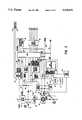
- FIGS. 3 and 4are schematic diagrams showing the major electronic circuits and components contained within the terminal of FIGS. 1 and 2 and the interconnections between them, FIG. 4 showing preferred circuit details for the power control components of FIG. 3.
- FIG. 5is a plan view showing the interior of the end cap of the terminal shown in FIGS. 1-4.
- FIG. 6is a perspective view of an embodiment including the basic terminal of FIGS. 1-5 and further including provision for on-line radio frequency communications capability.
- FIG. 7is an exploded perspective view of the modular adaptor end cap of the embodiment of FIG. 6.
- FIG. 8is an exploded perspective view of the embodiment of FIG. 6.
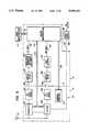
- FIG. 9is a block schematic diagram showing the electronic system components of the embodiment of FIG. 6.
- FIG. 10is a block schematic diagram similar to FIG. 9, but showing an improved circuit arrangement for facilitating interchangeability of the RF end cap module and in particular avoiding the need for any tuning adjustments when an RF end cap module is applied to the basic terminal in the field.
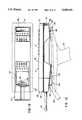
- FIG. 11is a somewhat diagrammatic perspective view showing a modular hand-held data capture device in accordance with the present invention.
- FIG. 12is a side elevational view showing a RF data terminal in solid lines, and indicating with dash lines a scanner module which is mated therewith, to form the unitary hand-held data capture device of FIG. 11.
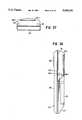
- FIG. 13is a top plan view of the scanner module which forms part of the data capture device of FIG. 11.
- FIG. 14is a side elevational view of the scanner module of FIG. 13, showing the handle detached but in vertical alignment with its attachment position, and showing locating studs on the handle which fit into the scanner body during assembly therewith.
- FIG. 15is a bottom plan view of the scanner body, showing the sealed slots which serve to locate a handle therewith.
- FIG. 16is a front end elevational view of the data capture device of FIG. 11.
- FIG. 17is a rear end elevational view of the data capture device of FIG. 11.
- FIG. 18is a somewhat diagrammatic side elevational view, similar to FIG. 12, but illustrating with dash lines a modification wherein the scanner module is provided with contacts at a rear end thereof for engagement with the external set of contacts of the terminal unit.
- FIG. 19is a diagrammatic view indicating an exemplary lay-out of parts within the scanner module of FIGS. 11-17 or FIG. 18.
- FIGS. 20, 21 and 22are somewhat diagrammatic plan, side elevational and end views showing a modular data capture system wherein the user interface module and the peripheral modules are readily removed and replaced with modules of the same or different characteristics.
- FIGS. 23, 24 and 25are somewhat diagrammatic plan, side and end views wherein the user interface module of FIGS. 20-22 has been replaced by a much wider version, also illustrating the case where a peripheral module may provide a forwardly directed automatic reader as well as an RF communications link.
- FIGS. 26, 27 and 28are somewhat diagrammatic plan, side elevational, and end views wherein the user interface module is of intermediate size and wherein a compact automatic reader scans along a horizontal path when the long axis of the terminal is disposed vertically.
- FIGS. 29, 30 and 31are somewhat diagrammatic plan, side and end views wherein the terminal corresponds with that of FIGS,. 20-22 except that a peripheral module is designed to accommodate a conventional rotary prism laser scanner.
- FIGS. 32-35are side elevational, plan and opposite end views of a further modular terminal configuration in accordance with the present invention.
- FIGS. 36 and 37are side and end views showing the basic user interface and battery/control modules of FIGS. 32-35, but with the radio frequency communications/scanner module of FIGS. 32-35 replaced by an RF communications module.
- FIG. 1shows a portable hand-held data capture terminal 10 embodying aspects of the present invention.
- the terminal 10has an elongated housing formed of parts 11 and 12, the back housing part 12 of which is formed in a manner so as to enable a user to hold the device comfortably in one hand for extended periods of time.
- terminal 10may be powered by a rechargeable nickel-cadmium battery pack 28 (FIG. 2) or a plurality of AA size batteries.
- a rechargeable nickel-cadmium battery pack 28(FIG. 2) or a plurality of AA size batteries.
- terminal housing 11, 12Enclosed within the terminal housing 11, 12 are four permanently mounted printed circuit boards 26, 37, 41, and 43, (FIG. 2), namely a host printed circuit board 37, a display printed circuit board 43, a keypad printed circuit board 41, and a peripheral controller printed circuit board 26. Interconnections between the circuit boards are accomplished through a plurality of pin and socket type connectors including pin type connectors 86 and mating receptacle type connectors 87. An exception is the interconnection between display board 43 and keypad board 41 which is accomplished through a resilient conductive pad 42.
- front housing part 11 and back housing part 12are joined together by a plurality of screws 88.
- the front housing part 11 of the terminal 10provides a mounting platform for a display 13 (FIG. 2) which may provide a visual indication of various types of information.
- display 13is of a liquid crystal display (LCD) variety providing sixteen lines, with twenty characters per line, of display area.
- the display 13may be of a four line type.
- the display 13may be mounted upon a display printed circuit board 43 which is then mounted or secured to front housing part 11 by a plurality of screws 58.
- the front housing part 11may provide a mounting platform for a keypad 14 (FIG. 1), having a plurality of keys 56 thereon.
- keypad 14is provided with either twenty-three or forty keys.
- the control and interface circuitry for keypad 14may be contained on keypad printed circuit board 41 (FIG. 2) which is mounted or secured to front housing part 11 by a plurality of screws 59.
- Conductive pad 42may contain a plurality of generally parallel, spaced apart conductive elements embedded within it.
- the overlapping portions of display printed circuit board 43 and keypad printed circuit board 41each contain a plurality of coplanar, generally parallel, and evenly spaced apart connector elements 60 and 61, respectively.
- conductive pad 42when conductive pad 42 is mounted between the overlapping portions of keypad printed circuit board 41 and display printed circuit board 43, are in positive contact with corresponding aligned connector elements 60 and 61, and provide respective paths for the transfer of electrical signals therebetween.
- the required electrical interconnections between display printed circuit board 43 and keypad printed circuit board 41may be accomplished through a flexible multi-conductor ribbon type cable.
- the back housing part 12 of the terminal 10may provide a mounting platform for a removable, elastic type flexible strap 15 (FIG. 2).
- Flexible strap 15may allow the user of the terminal 10 to relax the user's grip on the terminal 10 for short periods of time, without actually removing the terminal 10 from the user's hand.
- the flexible strap 15may be secured to the bottom of housing part 12 by means of two retaining clamps such as 16 (FIG. 2).
- Retaining clamps 16are secured to housing part 12 through the use of screws such as 57, with two screws 57 securing each retaining clamp.
- retaining clamps 16may be removed with simple hand tools, allowing the flexible strap 15 to be easily replaced.
- housing part 12Beneath the flexible strap 15 and generally between retaining clamps 16, the bottom of housing part 12 is contoured in such a way that, when the terminal 10 is being held by the user, the user's hand is placed on a recessed area 62 (FIG. 1) in housing part 12 and beneath flexible strap 15.
- the top end of the terminal 10may be enclosed with a removable end cap 18.
- End cap 18is attached with two screws 64 to housing part 12.
- end cap 18overlies and encloses cavity 63.
- Located on, and part of the end cap 18may be a multiple pin D-sub type connector 19, which may in turn be direct or hard wired via a flexible multi-conductor ribbon type cable 20 to a connector platform 21, on which may be mounted two connector receptacles 22 and 23.
- Cable 20, connector platform 21 and connector receptacles 22 and 23may also be mounted on and be part of end cap 18. Screws such as 24, FIG. 2, may secure parts 21, 22, 23 in a precise location with only connectors 22, 23 projecting beyond the confines of the end cap housing.
- the multiple pin D-sub connector 19may provide a communications port capable of the two-way transfer of data with other compatible devices according to the RS-232C standard as defined by the Electronic Industries Association.
- end cap 18When end cap 18 is installed on terminal 10, receptacles 22 and 23 automatically mate with a plurality of pins 67 and 68 which protrude through connector blocks 69 and 70. Pins 67 and 68, and connector blocks 69 and 70 are each attached or connected to peripheral controller board 26.
- the end cap 18may be removable using common hand tools.
- a plain type of end cap housingwhich does not contain a D-sub connector 19 or any of its associated components such as 20-23, may be used in place of end cap 18.
- peripheral controller board 26provides the electronic circuitry required to interface the two-way data transfer which may occur through D-sub connector 19.
- controller board 26may be a peripheral type device which may be exchanged or otherwise configured toenable the use of various types of end cap devices. These various end cap devices may enable terminal 10 to perform a wide variety of functions not currently possible with existing hand held data capture devices including, but in no way limited to, the two-way transfer of data through space using radio frequency waves as the data carrying medium, the two-way transfer of data over telephonic communication links, and the two-way transfer of data between the terminal and a bar code reading device.
- the cavity of the housing part 12 receiving the battery pack 28may be enclosed by a battery compartment hatch 27.
- the battery compartment hatch 27may have attached to its surface a plurality of conductive metallic type contacts 30.
- Metallic contacts 30, in conjunction with a plurality of metallic springs located in the battery compartment,may complete the electrical path of the batteries enclosed in the battery compartment.
- the battery compartment hatch 27When the battery compartment hatch 27 is properly installed on the terminal 10, it comes in contact with a conductive metallic rod which extends the length of the battery compartment and is hard wired to battery supply connector 71, FIG. 2, and completes the ground or negative potential path for the batteries.
- the enclosed batteriesare arranged in the battery compartment in a series type configuration to provide the required voltage.
- Battery supply connector 71contains a plurality of receptacles which mate with host board 37 to provide the battery power to the terminal 10.
- Battery compartment hatch 27attaches to the bottom housing part 12 of terminal 10 through the interlocking and meshing of railings on both the battery compartment hatch 27 and bottom housing part 12.
- the battery compartmentis formed by a cavity within terminal 10, with a somewhat rectangular opening on which three corners are rounded and one corner is somewhat squared.
- Battery pack 28may be constructed of a plurality of nickel-cadmium battery cells, arranged in such a way as to provide approximately six volts of direct current electrical power.
- battery pack 28may contain a formed metallic plate 31 which may be attached to the nickel-cadmium batteries in such a way as to form a somewhat squared edge on one corner 86 of the battery pack 28.
- the somewhat squared corner 86 (FIG. 2) of the battery pack 28may correspond with the previously described somewhat squared corner on the rectangular opening of the battery compartment, and may prevent the improper insertion of battery pack 28 into the battery compartment.
- metallic plate 31may be further formed to create a conductive metallic shunt 32 (FIG. 2).
- metallic shunt 32engages probes to create an electrically conductive path or short circuit between the probes.
- the probesmay form part of the battery charging circuit of the terminal 10 and may disable this circuit when not electrically shorted together, thereby preventing the inadvertent and possibly hazardous application of recharging electrical power to non-rechargeable (e.g. alkaline) batteries.
- the batteriescan be mounted in an enclosed drawer part with square and rounded edges, which slides endwise into a receiving compartment.
- External contacts on the drawermay be substituted for the array of external contacts as shown at 322, FIG. 11.
- the rear external contacts at the drawer external wallmay be connected with respective spring contacts at the forward end of the drawer which spring contacts engage with fixed contacts in the roof of the battery compartment as the drawer is fully inserted.
- a coin operated latchmay be rotatable through a given angular amount in one direction to lock the battery drawer in place, and may be rotatable in the opposite direction to unlock the battery drawer.
- a central processor unit (CPU) 74may contain program storage and reside on the host printed circuit board.
- CPU 74controls all terminal functions, executes machine instructions in proper sequence, and supervises data communication with devices inside and outside the terminal 10. However, it may allow an optional auxiliary processor unit on the peripheral controller board 26 to control some external access (e.g. reading from and/or writing to an auxiliary memory card).
- the CPU 74may abort all communications throughout terminal 10 should power available from the main batteries (e.g. nickel-cadmium battery pack 28) drop below a predetermined level. All access to static RAM 75, the real time clock 76, the keypad 14 and keypad circuit board 41, and display 13 and display circuit board 43 are accomplished through CPU 74.
- the CPU 74also controls the charging current applied to battery pack 28 by control of CHGON line 46, FIG. 4, and generates a signal on MEMON line 50 to initiate a sleep mode of the terminal. In addition, CPU 74 allows activation of the 485 circuit and watchdog timer component 77, RS232 level converter 78, and the backlight of display 13.
- the memory in static RAM 75is decoded in the decode circuit 79.
- MEMDIS line 83is coupled with this circuit and will inhibit access to static RAM 75 in the event the five volt regulator 80 has dropped out of regulation, indicating the installed batteries (e.g. nickel-cadmium battery pack 28) are no longer providing the necessary voltage.
- memory in the static RAM 75may be selectively configured in one of varying sizes.
- the terminal 10may be equipped with a battery/charge monitor circuit 81 as well as a battery charge circuit 82.
- the battery/charge monitor circuit 81monitors the main battery and provides a signal on the LOWBATT line if battery voltage drops below a certain value.
- the signal on the LOWBATT lineinforms the CPU 74 that battery power is getting low, and CPU 74 in turn will notify the user through the display 13.
- the terminal 10will continue to operate normally as long as the LOWBATT line remains in a high logical state. If the LOWBATT line goes low, the terminal 10 will switch to its inactive (sleep) state, but will be allowed to become active if a key 56 (FIG. 1) is pressed.
- a further output of the monitor component 81isthe DDEC line.
- the DDEC lineprovides a true indication if the five volt regulator 80 begins to drop out of regulation.
- the terminal 10switches to sleep mode promptly, saving all data in the static RAM 75, which will have backup power in the event that the main batteries are removed.
- the MEMDIS line 83will carry a low logical signal, causing the static RAM 75 to be disabled, the CPU 74 to be reset and the transistor 54 (FIG. 4), located in the power isolation circuit 84, to switch to nonconducting mode.
- the CPU 74is equipped with an analog input port which allows it to monitor several other battery/charge conditions.
- the signals available at this portmay provide information regarding the charge level, for example.
- Another signal which may be monitored hereis an extended duration signal emanating from the KEYINT line 85.
- the controller board 26may also provide an interrupt signal on PERINT line 86, which is made available to the CPU 74 on this analog port.
- the charge circuit 82is disabled unless a shorting mechanism (conductive metallic plate 32, FIGS. 2 and 4) which is located on and part of the nickel-cadmium battery pack 28, is present and properly installed in the battery compartment as described previously. Charging of an installed nickel-cadmium battery pack 28 occurs automatically when a charge voltage of a predetermined value is present on CHARGE line 87. Charging of the installed nickel-cadmium battery pack 28 may occur selectively at a rate of approximately twenty milliamps or a rate of approximately seventy-five milliamps, and is determined by the terminal software through CPU 74.
- the CPU 74also monitors the ambient air temperature and, if below a predetermined level, preferably approximately five degrees Celsius, the CPU 74 causes the LOWTEMP line 88 to provide a signal, which causes constant current charge to default to the lower charge (twenty milliamps) rate.
- a predetermined levelpreferably approximately five degrees Celsius
- the CHGDET line 89goes active for approximately four milliseconds, then returns to its inactive state. This causes NMI generator 90 to generate a pulse to wake the terminal 10 from its sleep mode and signal that a charger is present.
- a chargermust be attached to terminal 10 for the 485 circuit and watchdog component 77 to function, as this circuit is powered by the charger.
- the 485 circuit and watchdog circuitry 77may provide the terminal 10 with a communications port capable of synchronous two-way data communication with other compatible devices, transferring data at a rate not greater than five hundred thousand bits per second, according to the predominate RS485 standard as defined by the Electronic Industries Association.
- CPU 74detects the presence of a charger, it activates the 485 circuit and watchdog through 485ON line 91.
- RS485 DATA+line 92 and RS485 DATA-line 93may then be transmitted and received by terminal 10 on RS485 DATA+line 92 and RS485 DATA-line 93, these lines being connected to a pair of a number of coplanar, generally parallel and evenly spaced conductive metallic pads 322 (FIG. 11).
- Received datais applied to the CPU 74 from the 485 circuit and watchdog circuit 77 on 485RXD line 95, while transmitted data is applied to the 485 circuit and watchdog circuit 77, from CPU 74, on 485TXD line 96.
- Five volt regulator 80may operate from either the main battery supply or an attached charger. If both are present, the output voltage of the charger will e higher than the battery voltage, causing five volt regulator 80 to choose current from the charger supply rather than the batteries. This is accomplished through "OR" wiring of diodes 97 and 98.
- Terminal 10has been designed to be in an inactive state (sleep mode) for the majority of time to conserve battery power.
- NMI line 55must be pulsed for terminal 10 to wake up and begin program execution.
- the pulse on NMI line 55is generated by the NMI generator 90 and may be generated by a pulse on KEYINT line from the keypad 14, a pulse on RTCINT line from the real time clock 76, simultaneous pulses on LOWBATT line and DDEC line, a pulse on CHGDET line 89, a pulse on PERINT line 86 from peripheral controller board 26, or a pulse on the PWRUP line (from the 5 V regulator 80).
- Poweris applied to the peripheral controller board 26 under the control of CPU 74.
- the controller board microprocessor(212, FIGS. 9 and 10) is stable, the controller board microprocessor begins a hand shaking sequence with CPU 74 to establish a communication link. This link has some software support to monitor data integrity throughout the transfer of data.
- the controller board 26is equipped with a pair of analog switches which isolate the data bus on the controller board 26 from the memory data bus on the host printed circuit board 37. This isolation prevents inadvertent data bus interference during the power up routine of the peripheral controller board microprocessor.
- a charging voltagemay be introduced on the CHRGX line (FIG. 4).
- the charging voltage on CHRGX line 43may then be applied to a voltage regulating device 44 e.g. type LP 2951 ACM.
- the regulated charging voltage output of regulating device 44may be applied to a transistor switch 45 through a resistor R73.
- Transistor switch 45may be software controlled, and may be activated or turned on when the signal on CHGON line 46 changes its logical state, which may cause field effect transistor 47 to change state which then may cause transistor switch 45 to change state.
- Transistor switch 45may provide a constant charging current through a diode CR3, to the installed battery pack 28, for a predetermined length of time.
- the charging currentmay be applied to installed battery pack 28 through metallic terminals in the battery compartment shorted by metallic shunt 32 on the battery pack, FIG. 2.
- the sleep mode circuitry of terminal 10monitors the input activity of the terminal 10 and, when no activity is detected for a predetermined length of time, may cause the terminal 10 to shift to a stand-by or sleep mode to conserve the power supplied by the installed batteries.
- the memory array and real time clock circuits of terminal 10require less power than when in an active state.
- MEMON line 50may pulse. This pulse may be sensed on the CLK input of flip-flop integrated circuit 51, which may cause its Q output to switch levels. Resistor R140 and capacitor C96 may ensure that no false signals are received by flip-flop 51.
- MEMSW line 52The Q output of flip-flop 51 is designated MEMSW line 52.
- the state of MEMSW line 52may cause field effect transistor 53 to change state.
- MEMSW line 52may be filtered by resistor R88 and capacitor C93.
- field effect transistor 53changes states, it greatly reduces the amount of current flowing through the base of transistor 54 by causing resistor R59 to be placed in series with resistor R60.
- the greatly reduced current flow through the base of transistor 54allows the regulated supply of the terminal 10, provided by the power of the installed batteries applied through a voltage regulating device, to provide less current, thus increasing the active life of the installed batteries.
- NMI line 55may pulse.
- the pulse on NMI line 55may be sensed by flip-flop 51, FIG. 4, at its CLR input, and may then cause the Q output of flip-flop 51 to change state.
- the state of MEMSW line 52, FIG. 4, at the Q output of flip-flop 51may now cause field effect transistor 53 to reset to its former state, returning current flow through the base of transistor 54 to its active level.
- the terminal 10may operate exclusively from the power supplied through a regulating device by the installed batteries (e.g. battery pack 28, FIG. 2) until the MEMDIS line 83, FIG. 4, changes state.
- the MEMDIS linemay change state when the installed batteries or attached charger do not provide sufficient voltage to operate the terminal.
- the MEMDIS linechanges state, it may change the state of field effect transistor Q15.
- the MEMDIS linemay be filtered by resistor R141 and capacitor C94.
- field effect transistor Q15changes state it may cause interruption of current flow through the base of transistor 54, effectively removing the regulated supply of terminal 10 from the memory array.
- a standby lithium battery or a charged capacitormay supply the memory array and real time clock circuits until such time that the main power supply is returned to the level required to power the terminal 10.
- a charged capacitormay provide short term back-up power for the terminal 10, with the lithium battery providing power when the stored charge of the capacitor is depleted.
- the lithium batterymay provide long term back-up power.
- the MEMDIS line 83, FIG. 4may return to its former state which may restore normal current flow through the base of transistor 54.
- FIG. 5is a view looking into the interior of end cap 18.
- Three screws such as 24secure the connector platform 21 at the correct position within the end cap 18.
- Two guide parts 38 and 39are precisely located so as to project into the open end 72 of housing part 11 and interfit with cooperating surfaces at the end 72 so as to insure that the connector receptacles 22, 23 are correctly aligned with pins 67, 68 as the end cap 18 is applied to the terminal.
- This type of mechanical guidancecould also be provided for the automatic electrical interconnection of all of the various modules herein which are to be mechanically joined with each other.
- terminal 110includes the basic housing parts 11 and 12 of FIGS. 1-5, and is further provided with a modular adaptor end cap 118. Antenna 104 and external connector fitting 119 are attached to the end cap 118. (Corresponding reference numerals have been applied to identical parts in FIGS. 1-5 and 6-10 and such parts need not be further described). Keys 56 are depressed by the user to enter data and to control the functions of terminal 110, including causing terminal 110 to transmit or receive data by radio transmission means. Display 13 provides visual information concerning RF transmissions received by the terminal.
- end cap 118may be readily removably mounted on housing parts 11 and 12.
- External connector fitting 119provides for interconnection to optional peripheral devices and is electrically connected through wiring 120 to connectors 122 and 123 which are mounted to connector platform 121.
- Connectors 122 and 123engage with the pins of mating connectors 67 and 68 (FIG. 2) of peripheral controller card 26 when end cap 118 applied to housing parts 11 and 12.
- Radio module 106mounts within end cap 118 by suitable mounting means such as indicted by screw 107 (FIG. 8), and is electrically coupled to peripheral controller card 26 by ribbon cable 108.
- Ribbon cable 108is detachably connected to radio module 106 by a connector 109 affixed to the end of cable 108, and enters housing part 11 through opening 65 in wall 66.
- Ribbon cable 108connects at 25, FIG. 2, with the peripheral controller card 26, and serves to interconnect radio module 106 and peripheral controller card 26.
- Adjusting elements 114(FIG. 8) are provided on radio module 106 for frequency tuning and signal level adjustment purposes.
- end cap 118comprises housing members 116 and 117 which may be separated when end cap 118 is removed from housing parts 11 and 12 in order to provide access to adjusting elements 114 of radio module 106.
- radio module 106houses transmitter 202 which is coupled to antenna 104.
- Transmitter 202is coupled to transmit level adjust circuitry 204.
- Receiver 206is coupled to antenna 104 and to receive level adjust circuitry 208.
- Dashed line Aseparates the components located on radio module 106 from components located on peripheral controller card 26.
- Control microprocessor 212communicates with main microprocessor 74, FIG. 3, of housing part 11 through coupling means 214 which is provided by connectors 86, 87, FIG. 2.
- Control microprocessor 212is coupled to transmitter 202 and receiver 206 by coupling means 216 along which are communicated radio control signals. Data to be transmitted is received from processing unit 74, FIG.
- Modulation generator and limiter component 220is coupled to first low pass filter 222.
- Data received by antenna 104is delivered to control microprocessor 212 on RX data line 223 which couples control microprocessor 212 to data recovery element 224 which is coupled to a second low pass filter 226.
- Lines 108a and 108b and also lines 216are part of ribbon cable 108 and serve to couple the circuitry of peripheral controller card 26 to radio module 106.
- External connector fitting 119is coupled to control microprocessor 212 by scanning interface signal lines 228 associated with connectors 67, 68, FIG. 2, and 122, 123, FIG. 8, and wiring 120, FIG. 8.
- Peripheral control adjustment elements 115are mounted to peripheral controller card 26 such that these adjustment elements 115 are accessible to the user through opening 65, thereby obviating the necessity of any disassembly of housing parts 11 and 12 in order to effectuate adjustments to the peripheral controller card 26.
- the usermay remove modular adaptor end cap 118 from housing parts 11 and 12 when adjustment of radio components is desired.
- Adjusting elements 114(FIG. 8) may be accessed by the separation of housing members 116 and 117 (FIG. 7) while radio module 106 continues to be electrically connected with peripheral controller components on card 26 through ribbon cable 108.
- peripheral control adjustment elements 115(FIG. 8) of peripheral controller card 26 (FIG. 2) may be accessed when end cap 118 is removed from housing parts 11 and 12.
- the usermay communicate with a remote host computer in "real time" by operation of keyboard 14 which provides signals to main microprocessor 74 (FIG. 9).
- Main microprocessor 74processes the signals and communicates them to control microprocessor 212 of peripheral controller card 26.
- Control microprocessor 212 and its associated circuitry on peripheral controller card 26processes the signals to superimpose them upon radio transmission frequencies, and communicates the processed signals to transmitter 202 which is coupled to antenna 104 and which thereby causes their transmission through space from antenna 104 by electromagnetic radiation.
- a remote host computer responding to terminal 110transmits radio frequency signals which are received by receiver 206 through antenna 104.
- Received signalsare processed on peripheral controller card 26 and are provided to control microprocessor 212 which communicates the processed signals to main microprocessor 74.
- Microprocessor 74displays the received information upon display 13 so that it can be observed by the user.
- FIG. 10shows a modification of the embodiment of FIG. 9 which enables the replacement of the RF adaptor module without requiring a tuning adjustment of the module.
- the control microprocessor 212is on the peripheral controller card, while components 220, 222, 224 and 226 are included in the radio module 106-1 forming part of the RF modular adaptor end cap 118-1. This results in a digital interface at 250 between the peripheral controller card of the basic terminal and the radio module of the RF adaptor end cap.
- the lines 216, 218 and 223may form part of a ribbon cable corresponding to cable 108 with a connector corresponding to connector 109 for plug-in coupling with a mating connector of radio module 106-1.
- Multiconductor line 228may be implemented via mating connectors such as 67, 22 and 68, 23 (FIG. 2) as in the previous embodiments.
- power from the battery pack 28may be supplied to the circuitry of the RF end cap under the control of a radio on/off switch 252, the power supply path 254, FIG.
- control microprocessor 212is coupled with switch component 252 as indicated at 256, so that all power to the RF end cap can be switched on and off as required to minimize battery drain.
- peripheral circuit means including 212, FIG. 10only transmits standardized digital signals and battery power to the modular adaptor end cap
- the end cap circuitscan be pre-adjusted at the factory and adjustments by the end user in assembling the modular adaptor end cap with the terminal can be avoided.
- the peripheral circuit board 26 (FIG. 2) and end cap 18can be replaced by peripheral controller board 126, FIG. 10, and the end cap 118-1 with radio module 106-1, without requiring any other hardware changes in the terminal. Then the end cap with radio module 106-1 can be replaced with a new identical end cap as needed without requiring any adjustments in the digital outputs from the peripheral controller board, and without requiring any tuning adjustments of the modular adaptor end cap.
- the basic hand-held terminal configuration formed from housing parts 11 and 12, FIG. 2,has peripheral adaptor circuit means 126, FIG. 10, connected therewith via peripheral connector means similar to 108, 109 (FIG. 8), accessible at the upper end of the terminal configuration (see FIG. 8).
- the basic terminalselectively receives a compatibility end cap (e.g. 18, FIG. 2) for enclosing the upper end and providing a resultant hand-held terminal of dimensions compatible with an existing terminal receptacle e.g. of a portable printer.
- the receptacle for the terminalhas an electrical connector at one end for mating with connector 19, FIG. 1, and a spring-urged retainer at an opposite end for retaining the terminal in operative relation to the printer receptacle.
- the basic terminal configurationmay be provided with peripheral adapter circuit means such as represented at 126, FIG. 10.
- the peripheral input/output means at digital interface 250, FIG. 10may be embodied in a cable and connector (such as 108, 109, FIG. 8) which is passively contained within a compatibility end cap module such as 18, FIG. 1, but is ready for plug-in connection with RF module 106-1, FIG. 10, of a modular adaptor end cap 118-1, FIG. 10.
- a unitary hand-held data capture device 310comprises housing parts 11 and 12 forming a data terminal body 311, a RF module 312 (corresponding to module 118, FIG. 9, or 118-1, FIG. 10), a scanner module body 313 and a handle 314.
- the data terminal formed by components 311 and 312has a frontal face 316 with user-device input and/or output interface means such as a manual data entry keyboard 14 and a display means at 13.
- the frontal facemay have an indentation pattern at 320 for assisting in the aiming of the device in relation to a data source such as a bar code label on a product container or the like.
- the terminal body 311has a set of external contacts 322 for coupling of power and data signals of various types.
- the RF module 312may include a stub antenna 104 projecting in a longitudinal direction
- the scanner body 313may include a scanner extension part 326 which serves to direct scanner energy (e.g. optical energy) obliquely to the general plane of the frontal operating panel 316. This serves to insure that under normal scanning conditions, the frontal panel 316 will be facing the user during scanning operation so that for example, the user can verify the scanner data as it appears on the display 13.
- scanner energye.g. optical energy
- FIG. 12shows the device 310 as having a rubber bumper 331, 332 extending about the exterior sides of the terminal body 311 and the RF module 312 to protect the device 310 against lateral impact.
- a connector 334 corresponding to connector 119, FIG. 8, e.g. a standard 15-pin D subminiature connector,may face longitudinally in a forward direction from a section 335 of the RF module 312.
- the connector 334may correspond in its pin assignments with the connector commonly present on RF terminals such as the model 2210 RF terminal of Norand Corporation, Cedar Rapids, Iowa.
- the connectorhas pins assigned to the transmission of scanner signals, RS-232 signals, charge potential, and power out, for example.
- the terminal body 311may contain rechargeable batteries in a battery compartment at section 337, and battery power may be supplied from the batteries to the RF module by a direct connection and via connector 334 to the scanner module.
- the scanner module body 313is provided with a connector 340 which is mated with terminal connector 334 during the assembly of the terminal parts 311 and 312 with the scanner module.
- a forward recess 343 of the scanner module body 313receives terminal housing sections 335, 338, while a rearward recess 344 accommodates a transverse rib 345, FIG. 12, on the terminal body 311.
- the scanner modulemay have six alignment holes 351-356, and four screw holes 357-360 for use in securing the terminal body 311 therewith.
- FIG. 14shows locating lugs 361, 362 on the handle 314 which interfit with sealed slots 371-374, FIG. 15, at the undersurface 375 of the scanner module 313.
- Four contacts 380 on the handle 314mate with respective cooperating contacts 381-384 at undersurface 375, so that for example the handle 314 may optionally contain batteries and supply battery power to scanner module 313.
- the handleis secured to the terminal by means of an integral internally threaded nut 385 at the undersurface 375 which likewise is sealed off from the interior of the scanner module.
- elements 371-374 and 385all present blind holes, so that handle 314 may be omitted without the introduction of any exposed apertures leading to the interior of the scanner module.
- batteriesmay be removed from the terminal body 311, and all operating power for the scanner and for the terminal keyboard and display and for the RF components may be supplied from batteries in the handle 314.
- a slide-off battery cap 386provides access to the battery compartment within handle 314.
- the handlemay have a trigger 390 for initiating a scan operation, and two of contacts 380 may serve as part of the scan trigger circuit.
- the terminal batteriesmay supply all operating power to the RF module 312 and to the scanner module 313, and in this case handle 314 may be omitted to provide a more compact unitary hand-held data capture device.
- scan trigger actuatorsmay be located at each side of the RF module 312 as indicated at 391, 392, FIG. 16. With this palm supported arrangement, the device may be held in either the right or left hand, and the convenient one of the trigger buttons 391, 392 actuated.
- FIG. 15shows a soft rubber guard 401 surrounding a scanner window 402 which may for example serve as an exit window for scan energy (e.g. light energy) and as an entrance window for return scan energy (e.g. modulated reflected light produced by an incident deflected light beam, or a simultaneous reflected light image where the incident light substantially simultaneously covers the entire data source line or lines such as a complete bar code symbol representing complete product information or the like).
- scan energye.g. light energy
- return scan energye.g. modulated reflected light produced by an incident deflected light beam, or a simultaneous reflected light image where the incident light substantially simultaneously covers the entire data source line or lines such as a complete bar code symbol representing complete product information or the like.
- center lines 410 and 411indicate the axes of elements 351-353, 357, 358 and 354-356, 359, 360, FIG. 13, and center line 412 shows the axis of the handle attachment screw which engages nut 385, FIG. 15, to secure the handle 314 in place.
- the scanner modulemay omit connector 340 or leave it unconnected electrically.
- the scanner module bodyis provided with an upstanding end part 420 having a set of spring fingers 421 which engage with the respective external contacts 322, FIG. 11, on the adjoining end of the terminal.
- the connectionsmay supply terminal battery power to the scanner module, or handle battery power to the terminal, as well as transmitting the same scanner signals between the scanner module and the terminal as in present types of cable connections between RF terminals and scanners.
- scanner powermay be supplied by batteries located in a compartment in section 425 of the scanner module.
- the center of gravity of the data capture device 310' of FIG. 18 and of data capture device 310 of FIGS. 11-17may be substantially as indicated at 427, FIG. 18.
- FIG. 19illustrates a layout of parts for the case of a scanner module which illuminates a bar code label or other data source simultaneously over its entire extent, the reflected light image being stored in an image sensor array such as a CCD image sensor array for electronic conversion into a scanner data signal.
- respective elements of the reflected light imagemay control the generation of charge in respective sensor elements, the charge states being simultaneously transferred to a shift register for readout as a serial scanner data signal.
- Illuminator 440(15, first figure; 35, third figure)
- Image sensor means 443(11, first figure) with photosensor 444 (13, first and third figures)
- Control and Processing Means 445(10, first figure).
- FIG. 19departs from the showing in the third figure of the referenced U.S. Pat. No. 4,877,949 in having the reflected image follow a single tier longitudinal path 450 in the relatively thin layer-like scanner module body 313.
- the thickness of the scanner module body 313may be substantially less than the thickness of the RF data terminal, for example.
- the reflected image pathis altered by a first mirror 451 and a second mirror 452 so that the image path 450 has a single tier path segment 450A within extension 326 and a single tier path segment 450B within the main section of the scanner module.
- a flex cable 460may extend from a main circuit board 461 to the illumination voltage generator 441.
- a sensor driver circuits component 463may be located adjacent photosensor 443.
- Control and processing means 445may comprise sensor control circuits 465, signal detection and shaping circuits 466 and control, communication, and decoding circuits 467.
- Component 467may include host I/O buffer means and host connection means (components 121 and 122 of the first figure of U.S. Pat. No. 4,877,949).
- Label guide indicator means (21, first figure), and intensity sensing means (14, first figure)are indicated at 471, 472 in FIG. 19.
- Illuminator 440may comprise one or more flash tubes or one or more series of LED sources.
- the RF data terminal 311, 312 as shown in FIGS. 10, 11 and 12generally may provide the features disclosed in U.S. Pat. No. 4,910,794 issued Mar. 20, 1990 and European Published Patent Application EP/0353759/A2 dated Feb. 7, 1990.
- the terminalwill run application programs downloaded to it, or permanently stored in it, or combinations of both.
- the scanner module 313is treated as an add-on peripheral to terminal 311, governed by the control microprocessor 212, as indicated in FIG. 10.
- the handle 314may contain additional batteries for extended operation, and to lower the center of gravity of the device 310 or 310'. An option would be to remove the batteries of the terminal to further lower the center of gravity of the device 310 or 310'.
- the intensity sensing means 471, 472may be used with a series of bright LED sources as illuminator, driven full on until a near saturation of the photosensor is detected, whereupon the LED sources could be turned off, so that they are treated as a single shot light source.
- a flex or rigid interface connectionmay extend between terminal 311 and RF module 312 above the level of sections 335 and 338.
- the antenna 104is offset laterally from connector 334 (FIG. 12) to avoid scanner/antenna electromagnetic interference issues, and may be formed with a right angle bend as at 324, FIG. 16.
- the length of antenna 104-1 beyond bend 324may be adjusted to various desired angular positions besides the horizontal disposition shown in FIG. 16.
- antenna element 104-1may be disposed vertically (as the data terminal is viewed in FIG. 16).
- the terminal control microprocessor 212controls the supply of battery power to the RF module as represented at 118-1, FIG. 10.
- the signal levels transmitted at the interface between the low pass filters 222, 226 of the terminal peripheral board 26, FIG. 9, and the transmit and receive level adjusts 204, 208 of the RF module 106, e.g. if used for RF module 312, FIG. 11,may be standardized to allow terminals and modules to be assembled independently, and then mated in final production, and interchanged in the field, without re-tuning in either case.
- the base-band processing circuitrycould be located in the RF module as in FIG. 10, and in this case digital signals would be transmitted at the interface 250 between the terminal and the scanner module.
- Exemplary scanner technologieswhich may be used in the scanner modules of the present disclosure include that of U.S. Pat. No. 4,882,476 issued Nov. 21, 1989 and that of U.S. Pat. No. 4,877,949 issued Oct. 31, 1989.
- the disclosures of U.S. Pat. Nos. 4,877,949 and 4,882,476are readily applicable to the reading of multiple line bar code indicia.
- a two dimensional bar code of multiple linescan be envisioned occupying an area of 12.25 square centimeters, e.g. a square with sides of 3.5 centimeters.
- marker beamsmay delineate a field of view of square or circular configuration (e.g.
- the multiline bar code or other area informationcan be at any random angular orientation within the field of view as delineated by the marker beams, and an area image of the field of view of proper resolution is recorded in a digital image memory, whereupon the digital image may be rotated to a normalized orientation for decoding, for example.
- a circular flash tube configurationwould be of particular advantage, it is also feasible to utilize linear flash tubes or series of pulse light sources arranged above and below a reader window of suitable configuration, e.g.
- a rectangular windowcapable of reading a single line bar code of a length such as five centimeters directly at the reading window, and because of the divergence of the marginal lines (and marker beams) defining the field of view, also capable of reading a single line bar code at any random angle providing the bar code is at a suitable distance from the reader window.
- the same area reader apparatuswould then register a substantial number of line segments of a single bar code as a digital image made up of multiple image lines, or would provide the resolution in orthogonal directions so as to read a multiple line stacked or high density area type bar code pattern of any desired density.
- a particular advantage of the concepts of modular automatic reader units and modular automatic wireless communication unitsresides in the ability to adapt these units readily to ever more advanced technological developments, and to adapt the data terminal embodying such modules to a wide diversity of users or applications. For example, modules adapted to different size hands and to left-handed and right-handed users are conceivable. Also various user handicaps could be accommodated.
- FIGS. 20-22illustrate a modular hand-held data terminal 510 comprised of a user interface terminal portion or module 511 and a hand-held terminal part 512 joining the interface terminal portion along a juncture plane as indicated at 513.
- the user interface terminal portion 511may be comprised of a main keyboard 515 having forty-nine manually actuatable selectors, a display 516, and a set of special keys 517 which may have a readily removable label panel 518 associated therewith so that label indicia for the respective keys 517 may be readily changed.
- the hand-held terminal part 512may be comprised of a battery/controller module 521 with a rounded grip-conforming configuration 522 having a hand strap 523 longitudinally spanning the same.
- the hand strap 523may be of elastic material and may have hooks 525, 526 which are maintained engaged in receiving blind apertures by virtue of the resiliency of the strap.
- Module 521is illustrated as having elongated grooves 531 (FIG. 21), 532 (FIG. 25) which are adapted to receive the fingers of the left or right hand, respectively, when engaged with the grip-conforming configuration 522.
- module 521may have a D-subminiature nine pin connector 534 and a further connector 535 which may for example be specifically designed to receive a charger connector of a battery charging unit.
- the hand-held terminal part 512may further comprise a radio module 540 having an antenna 541 and a fifteen pin D-subminiature connector 542 which is part of an end cap 543.
- Module 540provides a downwardly protruding shoulder portion 549 for engaging the user's hand at one end of grip conforming configuration 522.
- FIGS. 23, 24 and 25illustrate the case where the user interface terminal portion or module 511 of FIGS. 20-22 has been replaced by a substantially wider user interface module 511-1 which is readily attached to the hand-held terminal part 512, FIG. 21, or to the similar hand-held terminal part 512-1 of FIGS. 24 and 25.
- components 515-1, 516-1 and 517-1 of FIG. 23generally correspond with parts 515, 516 and 517 of FIG. 20, except for differences in size, spacing and arrangement.
- Module 511-1is shown as having a protected recess area 550 for accommodating an antenna 541-1 which can be retracted as shown in FIG. 24 so as to be substantially fully protected by the surrounding walls of module 511-1.
- FIG. 24shows the case where the hand-held terminal part 512-1 comprises a peripheral module 540-1 which may include both a wireless communication unit such as a radio transceiver and also an automatic indicia reader unit such as the optical type of full image automatic reader unit as previously described.
- Module 540-1is shown as having manually actuatable selectors 551, 552 and 553, preferably of different geometric shape and arranged for actuation by the hand engaging the module 512-1 at 522, 549-1. As shown in FIG. 22, there is preferably a corresponding set of selectors such as 561, 562 on the opposite side of module 540-1, so that the selectors are conveniently actuatable by whichever hand is gripping hand grip portion 522.
- the strap 523stabilizes the support of the data terminal during manual actuation of selectors such 551-553.
- the peripheral module 540-1may have an optical reader window such as indicated at 402, FIG. 16, for effecting reading of a complete line or multiple complete lines of indicia such as bar code symbols.
- FIGS. 26-28show a different configuration of user interface module 511-2 applied to hand-held terminal part 512 which may correspond identically to that of FIGS. 20-22.
- the user interface module 511-2may have a main keyboard 515 corresponding identically to that of FIG. 20, for example.
- the width of display 516-2may however be intermediate the widths of displays 516 and 516-1.
- the arrangement of keys 560facilitates providing software labels for these keys by means of the adjacent portions of the display 516-2, where desired.
- the strap 523facilitates the use of the fingers of the left hand to support overhanging portion 564 of the module 511-2 during manual actuation of the keys 560.
- the module 511-2is indicated as including an automatic full line image reader unit 570 which may include an optical window as indicated at 571 which is directed transversely to the longitudal axis of the data terminal.
- an automatic full line image reader unit 570which may include an optical window as indicated at 571 which is directed transversely to the longitudal axis of the data terminal.
- the data terminalis held edgewise during an automatic reading operation, and then may be turned through about ninety degrees about its longitudinal axis so as to place the user module 511-2 into its normal orientation for user actuation of the keys and for user observation of the display 516-2.
- modules 511 and 521may be identical to those described with respect to FIGS. 20-22, for example.
- Module 540-2may generally correspond with module 540 except that an automatic reader unit 570-1 is applied as an end cap to module 540-2 in place of end cap 543, FIG. 21.
- Module 540-2is shown as having a swivel type belt clip 573 so that the data terminal can be conveniently supported from a belt or the like worn by the user.
- the automatic reader unit 570-1may contain an optical window at 574 and may be of configuration so that the data terminal is to be held generally edgewise during an automatic reading operation and then turned through ninety degrees about its longitudinal axis to place the keyboard 515 and display 516 in the optimum orientation for user interaction therewith.
- the optical window 574may be rectangular and have its long axis substantially parallel to the complete lines of bar code indicia to be read by the automatic reader unit 570-1.
- FIGS. 32-35show a particularly compact and light weight hand-held data terminal 610 comprising a user interface terminal portion 611 and a hand-held terminal part 612 joined therewith along a juncture plane indicated at 613.
- the user interface terminal portion 611 in this embodimentmay include a keyboard 615 and display 616 generally corresponding to any of the keyboards herein.
- Connectors 634 and 635, FIG. 35may correspond with connectors 534, 535, FIG. 25, except that in FIG. 35, the connector 634 is associated with printed circuit boards within the user interface terminal portion 611, rather than being associated with modules which provide hand grip portions such as 521, FIGS. 21, 24-25, 27, and 30-31.
- the hand-held terminal part 612may be comprised of a hand grip part 621 and a peripheral module 640.
- the hand grip part 621is provided with a grip-conforming configuration 622 which is of longitudinal extent to receive the user's hand and is of a rounded configuration so as to comfortably conform to the user's grip.
- a battery coveris diagrammatically indicated at 624 for providing access to a battery compartment which may occupy the major part of the space of hand grip portion 621.
- the peripheral module 640may contain automatically operating transducer means comprised of an automatic wireless communication unit and an automatic full image reader unit and thus correspond in this respect with module 540-1 of FIG. 24.
- the module 640may be provided with an antenna 641 corresponding with antenna 541 of FIG. 21, or the module 640 may be provided with an antenna corresponding to antenna 541-1 of FIGS. 23 and 24.
- An optical windowis indicated at 642 which may generally correspond with the window 402 of FIG. 16 where the automatic reader unit corresponds to an optical reader unit such as described with reference to FIGS. 11-19.
- the window 642may be housed in a reader extension part 643.
- module 640may in the usual case for an optical scanner include a source of light energy for directing light energy outwardly through the window 642 along an axis such as indicated at 645 for illuminating indicia such as a complete line or complete lines of bar code symbols on a label or the like lying at any of a substantial range of distances in front of the window 642.
- the label with indicia to be readmight lie at an optimum focal plane 646, or might lie in some other plane within the operative range of the automatic reader unit such as the plane arbitrarily indicated at 647.
- Reflected light energymay travel along a reflected light energy path such as indicated at 648 which passes through the window 642 and into the interior of the module 640 for conversion into a digital video image, for example, as previously described.
- the antenna 641may have a right angle bend portion so that the main antenna part may extend transversely as indicated at 641-1 in FIG. 34, and may be rotatable from a horizontal disposition such as shown at 104-1 in FIG. 16 to an upright disposition, for example, (as viewed in FIG. 16).
- module 640may provide a downwardly curved shoulder portion 649 which may comfortably engage the side of the hand which is in a gripping relation to the hand grip portion 621.
- a similar shoulder configurationis indicated at 549 in FIGS. 21, 27 and 30, and at 549-1 in FIG. 24.
- Manually actuatable selectorssuch as 651, 652 in FIG. 32 may be located symmetrically on each side of the module 640 and may correspond with selectors such as indicated at 551, 552, 561, 562 of FIGS. 22, 28 and 31.
- FIGS. 36 and 37show an identical user interface terminal portion 611 and an identical hand grip terminal portion 621, but show the module 640 replaced by a module 640-1 which may contain only a wireless communication unit such as a radio transceiver.
- Module 640-1may have manually actuated selectors such as 651-1, 652-1 symmetrically arranged on the respective sides thereof as in the previous embodiments.
- antenna 641-1is shown as being of the right angle type capable of swiveling from a horizontal position such as shown in solid outline in FIG. 33 to an orientation perpendicular to juncture plane 613, for example. This type of antenna is of course also applicable to FIGS. 36 and 37.
- a pair of antennasmay be located as indicated at 741, 742, FIGS. 36 and 37, and these antennas may be of a fixed type covered by the dielectric of the module housing so as to be completely enclosed, or for example, embedded in the dielectric walls of the module so as to be partially exposed. It is also possible that various flat type antenna configurations could be located within the dielectric walls of the module 640-1, for example located as generally indicated at 741-1.
- the antennas 741 and 742could also be of the retractable/extendable type as indicated at 541-1, FIGS. 23, 24. All such antenna arrangements are applicable to each of the embodiments herein including the module 640 of FIGS. 32-35.
- a data terminalmay be used in storing goods in predetermined locations, in collecting a list of items from storage locations, or in transferring incoming product directly to outgoing transport means.
- the data terminalmay be used to automatically read product identifying labels at a receiving dock, and to transmit such identifying data e.g. via an RF link to a host computer.
- the host computerthereby collects data which has been "captured" by the data terminal, concerning arriving product.
- the central computermay transmit to the data terminal a list of storage locations where the respective incoming items are to be stored.
- a location label at the storage bin and the product labelmay be read, and a quantity entered manually at the data terminal to indicate to the host computer the actual change in quantity at the storage location.
- the central computeris collecting data actually “captured” by the data terminal in the course of the relevant activity.
- the automatic operations to be performed by the hand-held data terminalare herein termed "data transducing" operations.
- data transducing operationsFor example, in an automatic reading operation, product identification and storage location indicia may be read by transforming reflected light information or electromagnetic code impulses (from a so-called RF tag) into data signals corresponding thereto.
- RF tagelectromagnetic code impulses
- wireless communication data signals within the data terminalare converted to an energy field (e.g. acoustic, inductive, radio frequency or infrared).
- a terminal moduleis a component of a data terminal which is readily removed and readily replaced with the same or different type of component.
- a detailed exampleinvolves components such as 18, FIGS. 1, 2, 5, and 118, FIGS. 6, 7 and 8.
- modulessuch as 18 (FIG. 5), 118 (FIG. 9), 118-1 (FIG. 10), 311-314 (FIGS. 11-19), 511 (FIGS. 20, 29), 511-1 (FIG. 25), 511-2 (FIG. 26), 521 (FIGS. 21, 24, 27, 30), 540 (FIGS. 21, 27), 540-1 (FIG. 24), 540-2 (FIG. 30), 640 (FIG. 32), 640-1 (FIG. 36), the corresponding modules have quick-connect, quick disconnect coupling means exclusively, such as coupling means 38, 39, 22, 23, 67, 68 (FIGS. 2, 5), 86, 87 (FIG. 2), 122, 123 (FIG. 8), 322 (FIG.
- the quick action coupling meansmay be based on self aligning pin and socket type electric or optic connectors where parts interfit when within the tolerance range of the guiding parts (such as 38, 39, FIG. 5) or may involve directly engaging surface contacts, or various optical or inductive couplers that merely require alignment within the tolerance range.
- all such modulesare readily removed and replaced in the field by the end user, with the use at most of simple hand tools, and with standardized interface levels such that no tuning adjustments or the like are required.
- a preferred type of modulecan readily be disconnected, removed as a unit, and replaced with a spare or a different type part.
- the preferred type of modulehas defined performance characteristics which permit it to be tested and adjusted as a separate unit, prior to assembly with other terminal components.
- modules hereinare disclosed as being capable of operation separately from other normal components of the data terminal.
- end cap modules 18, 118, and 118-1may be replaced with a simple cover piece which omits connector 19 and all internal parts except e.g. guides 38, 39 (FIG. 5).
- modules 311 and 313, 314, or 313 alonemay have their own batteries (e.g. at 337, and at 314, FIG. 11, and at 425, FIG. 18).
- Module 313has a hand grip region at 375 by which module 313 can be held in the absence of modules 311 and 314.
- Modules 311, 312, 313can be held at 375, 62, in the absence of module 314, and may have individual battery power at 337, 425, or either battery location may supply operating power for all of the modules.
- modules such as 511, 511-1, 511-2may contain battery compartments capable of containing batteries which enable separate operation of such modules.
- a dummy hand-grip module 521 without batteries in its battery compartmentmay serve the mechanical function of a hand grip only.
- module 511-1may contain a wireless communication unit associated with antenna 541-1 and operated from its own battery power, or battery power from module 521, with peripheral modules such as 540, 540-1, and 540-2 all omitted.
- the modules of FIGS. 20-31are preferably essentially completely enclosed and themselves protected from electrostatic discharge, dust, moisture and other contaminats, e.g. to facilitate storage, handling, and separate use as here described.
- An automatic reader such as 570, FIG. 26,may be operable as part of module 511, 511-1 or 511-2, from battery power within this module or from handle module 521, in the absence of any peripheral module such as 540, 540-1 or 540-2.
- a wireless communication unit connected with antenna 541-1may be associated with such a single module or two module system.
- the interface module or the handle modulecould contain extensive memory, facilitating batch operation of the one or two module systems.
- the hand-held terminal parts 512, 512-1, 512-2may also operate entirely separate from the user interface terminal module 511, 511-1, 511-2.
- the peripheral module 540, 540-1, 540-2is already shown as containing manually actuatable selectors such as 551-553, 561, 562, which may act as manual data input/function selector means.
- Additional user interface meansmay include use of marker beams of the automatic reader unit which may flash distinctively or in different colors to signal a good or bad read.
- a sound generatormay generate various tone patterns to communicate with the user as to mode selected, good read, etc.
- modules 540, 540-1, 540-2may contain voice recognition and/or voice synthesis devices to facilitate user supervision of the terminal parts 512, 512-1, 512-2.
- Such voice input/output interface meansmay be located on the side face of module 540, 540-1, 540-2 opposite the reader optical window such as 571 or 574, so that the orientation of the terminal part during automatic reading is essentially identical to the normal orientation which is optimum for user interaction with the voice recognition input and with the voice synthesis output of the module. That is the input microphone and output loudspeaker would be directed toward the user, while the optical window such as 571 or 574 would be directed away from the user, the longitudinal axis being generally vertical, and the juncture plane generally bisecting the user, and being generally at right angles to the plane of a label being read.
- Modules such as 511, 511-1, 511-2 when self poweredmay be constructed so that their coupling means (e.g. acoustic, infrared, inductive, etc.) are operable e.g. directly across the juncture plane 513 in the full data terminal configuration, and also at various distances from the hand-held terminal part 512, 512-1, 512-2.
- their coupling meanse.g. acoustic, infrared, inductive, etc.
- the interface part 511, 511-1, 511-2can be conveniently mounted on a goods transport device while the user may leave the transport device to actually handle products being collected or put away.
- the part 512, 512-1, 512-2can be carried at the wrist or forearm with both hands free when needed.
- the module 511, 511-1, 511-2can display a put away list of items and locations, or a pick list of goods to be collected and locations thereof, and be referred to when the operator returns to the transport device.
- the grooves 531, 532may facilitate mounting the complete data terminal or terminal part 512, 512-1, 512-2 in a holder which may provide two ribs designed to engage in the respective grooves, and to rest against the end walls 531A, 532A at the upper ends of the grooves.
- the hand strap 523may be compressed toward hand grip 522 as the part 512, 512-1, 512-2 is lowered into such a holder e.g. where the holder is affixed to a belt on the user's waist.
- the different width modules 511, 511-1, 511-2are not a problem (as they would be with an enclosing holster type carrier).
- a docking system for receiving terminal part 512, 512-1, 512-2 for recharging of batteries, and data uploading to a host and/or data or program downloading to the terminalmay similarly have ribs designed to engage in the respective grooves 531, 532.
- the user interface terminal module 511, 511-1, 511-2may be provided with blind undercut slots or blind keyhole type slots for receiving the hooks 525, 526 or other end fittings of a resilient hand strap 523 when module 511, 511-1, 511-2 is separate from part 512, 512-1, 512-2.
- the module 511, 511-1, 511-2may be worn on one wrist or forearm so as to face the user, while the terminal part 512, 512-1, 512-2 is worn on the other wrist or forearm in a disposition where an automatic reader such as 570 or 571-1 is ready for use. Again both hands can be available for the safe lifting of relatively heavy items to be stored, collected or transferred.
- a voice recognition unitmay conveniently control automatic reading operation and/or the reader may have a pulsed proximity detector for measuring distance and for automatically effecting a reading operation when a label is within the operative reading range.
- Pulsed marker beamscan be used to assist the user in keeping the label within the field of view once the distance measurement system is enabled until a valid reading has been obtained.
- module 511-2could be replaced with a module where window 571 was directed laterally to the left (as the user interface is to be viewed in FIG. 26), and overhang 564 and keys 560 were laterally to the left of part 512.
- module 540-2could be replaced with a module having a reader optical window directed in the opposite lateral direction from window 574, and e.g. an antenna on the opposite lateral side of the module from antenna 541, FIG. 31.
- antenna 541, FIG. 31,could be rearranged as described with reference to FIG. 32, and as shown at 741, 742 or 741-1, FIGS. 32, 34, to permit end cap 570-1 to form a separate module which may engage with module 540-2 in either of two opposite orientations, one as shown in FIG. 30, and the other with optical window 574 directed in an opposite sense.
- the module 570-1may contain its own battery, decoder and communication interface for serial communications of decoded bar code data signals over a central optical interface channel which is aligned with a cooperating optical channel of module 540-2 in either orientation of module 570-1.
- a base section of a reader modulee.g. containing batteries, decoder and communications interface could plug into a connector such as 542, carried by a peripheral module at 540-2.
- the reader module basewould occupy the space of reader unit 570-1 prior to window 574.
- the reversible part of the reader modulewould e.g. have a coiled cable secured with the base section so as to accommodate either of the opposite orientations of the window of the reversible part of the reader module.
- any of the terminals or terminal parts with automatic reader modulescould be clipped to the user's belt and used as hands free readers.
- a clipsuch as 573, FIG. 30, could mount terminals such as shown in FIGS. 27 and 30, with the longitudinal axis vertical, and could mount module 313 (without handle 314 or modules 311, 312) with the juncture plane vertical and the longitudinal axis horizontal.
- a belt clipsuch as 573 or two such clips could mount terminal 610, FIG. 32, with its juncture plane 613 vertical, so that reading axis 645 would be directed toward a work area in front of the user.
- An angularly adjustable extensionsuch as described for extension 326 could adjust the field of view to conveniently impinge on the work area.
- Pulsed marker beamswould facilitate the user's positioning of successive items, and distinctive sounds, marker beam flashes or colors, etc. could signal a successful read of each successive item.
- the reader modulecould operate in a proximity detect mode.
- the data terminalcould emit a distinctive sound whenever a label came within the field of view and within an appropriate range of distances, and actual reading would take place automatically (during an interval when all marker beams were off).
- the marker beamscould be pulsed automatically only when an acoustic proximity detector sensed that a label was in alignment with the field of view, so as to conserve battery energy during such hands free operation of the reader unit, if desired.
- Any of the displays hereinmay be capable of presenting any arbitrary graphical display, e.g. individual handwritten signatures, so that a person's signature can be compared with an authorized signature stored in the data terminal and displayed on the terminal display.
- the displays hereinmay incorporate high resolution digitizers. Where the digitizer is transparent, the digitizer field may be superimposed over the display layers. Signatures may be captured on a stroke sequence basis for dynamic comparison with a stored authentic signature. Pressure variations may also be stored and compared. See for example U.S. Pat. No. 4,793,810 issued Dec. 27, 1988, and U.S. Pat. No. 4,798,919 issued Jan. 17, 1989.
- a combined digitizer/displayis shown for example in U.S. Pat. No. 3,764,813 issued Oct. 9, 1973. This digitizer avoids the use of touch wires which would tend to obstruct the displayed information. It is apparent that a square digitizer/display, for example, may use angularly swept light beams e.g. at the four corners each sweeping the digitizer area. By using a square array of photosensors for following the successive sweeps, the stylus location could be accurately tracked. With multiple layers of photosensors, stylus pressure could also be recorded. Stepping motors, for example, could be used to sweep the light sources through ninety degrees clockwise during one scan, and then through ninety degrees counterclockwise for the next scan at each corner.
- Each laser sourcemay be pulsed on and off after each step of its stepping motor, and the stepping actions of the respective motors may be sequentially offset to minimize the interval between pulsing of the successive laser sources.
- Arrays of photodetectors along the sides of the digitizer areacould have single outputs since the pulsing of the laser sources would indicate the time when the absence of an output pulse represented a beam obstructed by the stylus.
- the production of rectangular cross section beams of good resolution over a substantial working distance and the cyclical deflection of such beamsare familiar to those in the field of laser bar code scanners, so that two or more laser sources would be sufficient for sensing both area position and contact pressure.
- the user interface means of any of the embodiments herein or replacement user interface modulesmay provide for handwritten printing or cursive data input including provision for signature capture and verification.
- optical full image automatic reader units disclosed herein or provided by replacement modulesmay have resolution to capture automatically a complete signature written on a delivery receipt or the like for digital storage and automatic validation based on a digitally stored authentic signature.
- a central aiming visible light beammay be pulsed whenever the acoustic range finder is active, to facilitate aiming of the optical reader.
- the aiming light beamis de-activated to save battery power, and flashing of the marker beams begins to facilitate bringing the multiple lines of indicia into the area field of view.
- the marker beamsmay diverge according to the increasing size of the field of view with increasing distance to more precisely delineate the field of view.
- the aiming visible light beamis also useful with directional type RF-tag systems, e.g. systems operating at relatively high frequencies.
- the flashing of the aiming lightmay be terminated automatically as soon as a valid reading has been obtained.
- the digital image obtainedcan be displayed on a display of the terminal along with a normalization line.
- the operatorcan rotate the normalization line with a manual control to indicate any pronounced slant of the signature or to indicate the angle of a single or multiple bar code stored image.
- the processing programcan rotate the stored image, and display the normalized signature or bar code image prior to validation processing or decoding.
- a bar code imagecan automatically be normalized before decoding for example, by detecting linear segments of memory cells which all represent dark pixels, and thereby establishing the slope of the bars of the bar code.
- Such an algorithmcan be designed to quickly locate a dark bar as a first step.
- a digital memorymay contain a bar code image representing a bar code three centimeters long by 1.7 centimeters tall, and within an area field of view four centimeters by four centimeters. By exploring horizontal lines of memory cells at one centimeter intervals and then exploring vertical lines of memory cells at one centimeter intervals, a given line of memory cells could be identified with the largest number of black pixels, (e.g. each assigned a value of one).
- the probable slope of a given black barcould be quickly ascertained.
- a checkwould be to examine a set of memory cells along a line at right angles to the probable slope of the bars. If such a line encountered the proper number of bars, the digital image could be rotated according to the probable slope value.
- a refinementwould be to select a sequence of black cells along the selected line closest to the minimum bar width since the slope of a minimum width bar is more accurately determined in a minimum of steps. Once the bars were approximately vertical in memory, spaced horizontal lines of memory cells could be examined, and further rotational correction could be effected if desired.
- Voice synthesis meanscould instruct the user to aim the automatic reader up or down, left or right, if the bar code image was found to be only partly registered in image memory.
Landscapes
- Engineering & Computer Science (AREA)
- Physics & Mathematics (AREA)
- Theoretical Computer Science (AREA)
- General Physics & Mathematics (AREA)
- Electromagnetism (AREA)
- General Engineering & Computer Science (AREA)
- Health & Medical Sciences (AREA)
- General Health & Medical Sciences (AREA)
- Toxicology (AREA)
- Artificial Intelligence (AREA)
- Computer Vision & Pattern Recognition (AREA)
- Computer Hardware Design (AREA)
- Business, Economics & Management (AREA)
- Human Computer Interaction (AREA)
- General Business, Economics & Management (AREA)
- Mechanical Engineering (AREA)
- Economics (AREA)
- Strategic Management (AREA)
- Emergency Management (AREA)
- Microelectronics & Electronic Packaging (AREA)
- Human Resources & Organizations (AREA)
- Marketing (AREA)
- Operations Research (AREA)
- Quality & Reliability (AREA)
- Development Economics (AREA)
- Tourism & Hospitality (AREA)
- Power Engineering (AREA)
- Entrepreneurship & Innovation (AREA)
- Computer Networks & Wireless Communication (AREA)
- Accounting & Taxation (AREA)
- Mobile Radio Communication Systems (AREA)
- Image Input (AREA)
- Facsimile Scanning Arrangements (AREA)
- Arrangements For Transmission Of Measured Signals (AREA)
- Communication Control (AREA)
- Two-Way Televisions, Distribution Of Moving Picture Or The Like (AREA)
Abstract
Description
Claims (135)
Priority Applications (10)
| Application Number | Priority Date | Filing Date | Title |
|---|---|---|---|
| US07/777,393US5410141A (en) | 1989-06-07 | 1990-06-07 | Hand-held data capture system with interchangable modules |
| US08/251,844US5539193A (en) | 1989-06-07 | 1994-05-31 | Modular hand-held data entry system |
| US08/389,830US5805474A (en) | 1989-06-08 | 1995-02-16 | Portable work station type-data collection system having an improved handgrip and an optical reader to be directed thereby |
| US08/444,619US5539194A (en) | 1989-06-07 | 1995-05-19 | Modular hand-held data entry system |
| US08/460,413US5747786A (en) | 1989-04-14 | 1995-06-02 | Communication module for a data capture system |
| US08/471,904US5679943A (en) | 1989-04-28 | 1995-06-07 | Hand-held terminal with display screens, interactive screens, magnetic credit card readers, scanners, printers and handlers |
| US08/489,887US5602456A (en) | 1989-04-14 | 1995-06-13 | Hand held computerized data collection terminal with rechargeable battery pack sensor and battery power conservation |
| US10/085,468US7120319B2 (en) | 1986-08-15 | 2002-02-28 | Data capture apparatus with handwritten data receiving component |
| US10/646,318US7712669B2 (en) | 1988-01-14 | 2003-08-22 | Hand-held data capture system with interchangeable modules |
| US11/475,472US7646941B2 (en) | 1986-08-15 | 2006-06-27 | Data capture apparatus with handwritten data receiving component |
Applications Claiming Priority (4)
| Application Number | Priority Date | Filing Date | Title |
|---|---|---|---|
| US36459489A | 1989-06-07 | 1989-06-07 | |
| US36490289A | 1989-06-08 | 1989-06-08 | |
| PCT/US1990/003282WO1990016033A1 (en) | 1989-06-07 | 1990-06-07 | Hand-held data capture system with interchangeable modules |
| US07/777,393US5410141A (en) | 1989-06-07 | 1990-06-07 | Hand-held data capture system with interchangable modules |
Related Parent Applications (5)
| Application Number | Title | Priority Date | Filing Date |
|---|---|---|---|
| US36459489AA-371-Of-International | 1986-08-08 | 1989-06-07 | |
| US36459489AContinuation-In-Part | 1986-08-08 | 1989-06-07 | |
| US36490289AContinuation-In-Part | 1986-08-08 | 1989-06-08 | |
| US36490289AA-371-Of-International | 1986-08-08 | 1989-06-08 | |
| PCT/US1990/003282A-371-Of-InternationalWO1990016033A1 (en) | 1986-08-08 | 1990-06-07 | Hand-held data capture system with interchangeable modules |
Related Child Applications (6)
| Application Number | Title | Priority Date | Filing Date |
|---|---|---|---|
| US81670592AContinuation-In-Part | 1989-04-28 | 1992-01-02 | |
| US98498092AContinuation-In-Part | 1989-01-31 | 1992-11-30 | |
| US08/251,844Continuation-In-PartUS5539193A (en) | 1989-06-07 | 1994-05-31 | Modular hand-held data entry system |
| US08/289,322Continuation-In-PartUS5515303A (en) | 1989-04-14 | 1994-08-11 | Hand-held computerized data collection terminal with rechargeable battery pack sensor and battery power conservation |
| US36001494AContinuation | 1986-08-15 | 1994-12-20 | |
| US08/389,830Continuation-In-PartUS5805474A (en) | 1989-06-08 | 1995-02-16 | Portable work station type-data collection system having an improved handgrip and an optical reader to be directed thereby |
Publications (1)
| Publication Number | Publication Date |
|---|---|
| US5410141Atrue US5410141A (en) | 1995-04-25 |
Family
ID=27002549
Family Applications (1)
| Application Number | Title | Priority Date | Filing Date |
|---|---|---|---|
| US07/777,393Expired - LifetimeUS5410141A (en) | 1986-08-15 | 1990-06-07 | Hand-held data capture system with interchangable modules |
Country Status (8)
| Country | Link |
|---|---|
| US (1) | US5410141A (en) |
| EP (1) | EP0667019B1 (en) |
| AT (1) | ATE250247T1 (en) |
| CA (1) | CA2020357A1 (en) |
| DE (1) | DE69034101T2 (en) |
| DK (1) | DK0667019T3 (en) |
| ES (1) | ES2210223T3 (en) |
| WO (1) | WO1990016033A1 (en) |
Cited By (322)
| Publication number | Priority date | Publication date | Assignee | Title |
|---|---|---|---|---|
| US5539194A (en)* | 1989-06-07 | 1996-07-23 | Norand Corporation | Modular hand-held data entry system |
| USD372480S (en) | 1995-04-17 | 1996-08-06 | Plantronics, Inc. | Cordless remote for headset |
| US5557507A (en)* | 1993-07-28 | 1996-09-17 | Kabushiki Kaisha Toshiba | Apparatus having shield structure |
| US5572007A (en)* | 1994-08-19 | 1996-11-05 | Intermec Corporation | Symbology reader with interchangeable window |
| US5574804A (en)* | 1990-12-21 | 1996-11-12 | Olschafskie; Francis | Hand-held scanner |
| US5576981A (en)* | 1993-11-17 | 1996-11-19 | Intermec Corporation | Portable computer with interchangeable keypad and method for operating same |
| US5576530A (en)* | 1995-05-11 | 1996-11-19 | Universal Data Incorporated | Portable data terminal including a scanning head that is secured to the terminal in a manner that allows the scanning head to be positioned in opposite orientations |
| US5590346A (en)* | 1993-07-26 | 1996-12-31 | Norand Corporation | Antenna cap for computer device utilizing a radio card |
| US5594470A (en)* | 1992-10-02 | 1997-01-14 | Teletransaction, Inc. | Highly integrated portable electronic work slate unit |
| US5600121A (en)* | 1995-03-20 | 1997-02-04 | Symbol Technologies, Inc. | Optical reader with independent triggering and graphical user interface |
| US5627977A (en)* | 1994-04-19 | 1997-05-06 | Orchid Systems, Inc. | Trainable user interface translator |
| US5637417A (en)* | 1995-11-07 | 1997-06-10 | Medtronic, Inc. | Quick change battery drawer for external electrical stimulator |
| US5654870A (en)* | 1995-12-08 | 1997-08-05 | Lucent Technologies Inc. | Battery drawer |
| US5659800A (en)* | 1993-10-06 | 1997-08-19 | International Technologies & Systems Corporation (Its) | System for directly sending undecoded raw signals from reader device via external slave interface to personal computer through communication port without first decoding the signals |
| US5698834A (en)* | 1993-03-16 | 1997-12-16 | Worthington Data Solutions | Voice prompt with voice recognition for portable data collection terminal |
| US5722055A (en)* | 1995-02-16 | 1998-02-24 | Fujitsu Limited | Portable radiotelephone terminal adaptable to multiple models |
| US5721421A (en)* | 1996-07-15 | 1998-02-24 | Bass, Inc. | Apparatus and method for verifying a shelf tag |
| US5726431A (en)* | 1996-06-20 | 1998-03-10 | Bass, Inc. | Apparatus for printing a shelf tag |
| US5736726A (en)* | 1996-03-29 | 1998-04-07 | Telxon Corporation | Portable data collection device having removable handle and battery |
| US5767500A (en)* | 1996-02-06 | 1998-06-16 | Symbol Technologies, Inc. | Automatic identification of hardware |
| US5801918A (en)* | 1996-07-12 | 1998-09-01 | Hand Held Products, Inc. | Ergonomic housing for a micro computer |
| US5805416A (en)* | 1995-09-11 | 1998-09-08 | Norand Corporation | Modular hand-held data capture terminal |
| US5822546A (en)* | 1996-03-08 | 1998-10-13 | George; Stanley W. | Hand held docking station with deployable light source, rechargeable battery pack and recessed grip, for connecting to a palm top computer |
| US5821523A (en)* | 1992-03-12 | 1998-10-13 | Bunte; Alan G. | Combined code reader and digital camera using a common photodetector |
| US5828052A (en)* | 1996-10-24 | 1998-10-27 | Intermec Corporation | Ergonometric modular hand-held scanner, including an ergonomic handle and hilt |
| USD400872S (en) | 1997-10-27 | 1998-11-10 | Hand Held Products, Inc. | Contoured housing |
| US5844985A (en)* | 1995-09-22 | 1998-12-01 | Qualcomm Incorporated | Vertically correcting antenna for portable telephone handsets |
| US5860015A (en)* | 1995-12-14 | 1999-01-12 | Gateway 2000, Inc. | Detachable palm rest with backup battery |
| US5878395A (en)* | 1995-12-08 | 1999-03-02 | Intermec Ip Corp. | Code reading terminal with integrated vehicular head-up display capability |
| US5917175A (en)* | 1989-06-07 | 1999-06-29 | Norand Corporation | Modular hand-held data entry system with voice interface |
| US5969328A (en)* | 1995-11-17 | 1999-10-19 | Intermec Ip Corp | Portable hand-held data terminal having curvilinear housing and keypad |
| US5983296A (en)* | 1995-05-02 | 1999-11-09 | Lsi Logic Corporation | Method and apparatus for terminating busses having different widths |
| US5979770A (en)* | 1997-06-26 | 1999-11-09 | Symbol Technologies, Inc. | Data acquisition device having a resilient seal interposed between the head portion and the handle portion for rest stand |
| US5983290A (en)* | 1993-11-09 | 1999-11-09 | Fujitsu Limited | Information processing system using portable terminal unit and data communication adapter therefor |
| US5991864A (en)* | 1993-04-27 | 1999-11-23 | Intermec Ip Corp. | Power connectors, antenna connectors and telephone line connectors for computer devices utilizing radio and modem cards |
| US6002946A (en)* | 1997-04-14 | 1999-12-14 | Motorola, Inc. | Handheld device having an optical data reader |
| US6010071A (en)* | 1992-05-15 | 2000-01-04 | Symbol Technologies, Inc. | Finger-mounted electro-optical scanner with on-board short range radio transmitter |
| US6023147A (en)* | 1989-04-14 | 2000-02-08 | Intermec Ip Corp. | Hand held computerized data collection terminal with rechargeable battery pack sensor and battery power conservation |
| US6029216A (en)* | 1997-06-27 | 2000-02-22 | Lsi Logic Corporation | Auto-termination method and apparatus for use with either active high or active low terminators |
| US6032866A (en)* | 1997-09-10 | 2000-03-07 | Motorola, Inc. | Foldable apparatus having an interface |
| US6043503A (en)* | 1998-07-22 | 2000-03-28 | Hewlett-Packard Company | Hand held scanning device |
| US6049813A (en)* | 1993-02-26 | 2000-04-11 | Intermec Ip Corp. | Portable work station-type data collection system |
| US6058304A (en)* | 1993-10-13 | 2000-05-02 | Dataquill Limited | Data entry system |
| US6058356A (en)* | 1998-04-30 | 2000-05-02 | Cooper Instrument Corporation | Hand-held electronic instrument |
| US6061806A (en)* | 1997-05-12 | 2000-05-09 | Lsi Logic Corporation | Method and apparatus for maintaining automatic termination of a bus in the event of a host failure |
| US6070206A (en)* | 1997-03-31 | 2000-05-30 | Lsi Logic Corporation | Method and apparatus for terminating a bus |
| US6091765A (en)* | 1997-11-03 | 2000-07-18 | Harris Corporation | Reconfigurable radio system architecture |
| US6092131A (en)* | 1997-07-28 | 2000-07-18 | Lsi Logic Corporation | Method and apparatus for terminating a bus at a device interface |
| US6089456A (en)* | 1995-06-07 | 2000-07-18 | E-Comm Incorporated | Low power telecommunication controller for a host computer server |
| US6097606A (en)* | 1998-05-28 | 2000-08-01 | International Verifact Inc. | Financial transaction terminal with limited access |
| US6109528A (en)* | 1995-12-22 | 2000-08-29 | Intermec Ip Corp. | Ergonomic hand-held data terminal and data collection system |
| US6112992A (en)* | 1998-06-17 | 2000-09-05 | Motorola, Inc. | Optical code reader and methods and articles therefor |
| US6123261A (en)* | 1997-05-05 | 2000-09-26 | Roustaei; Alexander R. | Optical scanner and image reader for reading images and decoding optical information including one and two dimensional symbologies at variable depth of field |
| US6123264A (en)* | 1994-06-30 | 2000-09-26 | Symbol Technologies, Inc. | Apparatus and method for determining a distance to a target |
| US6131813A (en)* | 1998-06-04 | 2000-10-17 | Motorola, Inc. | Optical code reader and methods and articles therefor |
| US6138151A (en)* | 1996-09-23 | 2000-10-24 | Motorola, Inc. | Network navigation method for printed articles by using embedded codes for article-associated links |
| US6137654A (en)* | 1997-06-23 | 2000-10-24 | Motorola, Inc. | Device having a diskette-like housing and a wireless transceiver and methods therefor |
| US6142378A (en)* | 1994-10-27 | 2000-11-07 | Fujitsu Limited | Replaceable emission-condensing unit for a bar code reader |
| US6147859A (en)* | 1999-08-18 | 2000-11-14 | Ops, Inc. | Modular external peripheral housing |
| US6154665A (en)* | 1996-10-23 | 2000-11-28 | Nokia Mobile Phones Limited | Radio telephone proximity detector |
| US6193159B1 (en)* | 1995-01-11 | 2001-02-27 | Fujitsu Limited | Portable optical reading apparatus having a trigger key for starting reading operation thereof |
| US6199044B1 (en)* | 1998-05-27 | 2001-03-06 | Intermec Ip Corp. | Universal data input and processing device, such as universal point-of-sale device for inputting and processing bar code symbols, document images, and other data |
| USD439898S1 (en) | 1996-03-18 | 2001-04-03 | Hand Held Products, Inc. | Contoured housing |
| US6226535B1 (en)* | 1998-09-21 | 2001-05-01 | Acer Peripherals. Inc. | Cellular telephone with an improved LCD supporting frame |
| US6230970B1 (en)* | 1995-06-07 | 2001-05-15 | E-Comm, Incorporated | Low-power hand-held transaction device |
| US6234396B1 (en)* | 1996-02-20 | 2001-05-22 | Opticon, Inc. | Optical pattern reading apparatus |
| US6244513B1 (en)* | 1999-11-09 | 2001-06-12 | Symbol Technologies, Inc. | Data acquisition apparatus |
| US6244512B1 (en) | 1989-06-08 | 2001-06-12 | Intermec Ip Corp. | Hand-held data capture system with interchangeable modules |
| US6260760B1 (en) | 1998-06-17 | 2001-07-17 | Motorola, Inc. | Optical code reader including circuitry for processing the symbology |
| EP0982923A3 (en)* | 1998-08-28 | 2001-09-05 | Hewlett-Packard Company, A Delaware Corporation | Converter for optical scanner |
| US6298175B1 (en)* | 1997-10-17 | 2001-10-02 | Welch Allyn Data Collection, Inc. | Object sensor system comprising controlled light source |
| US20020050523A1 (en)* | 1999-04-30 | 2002-05-02 | James T. Veligdan | Integrated display scanner |
| US20020054676A1 (en)* | 2000-11-07 | 2002-05-09 | Wen Zhao | Multifunctional keyboard for a mobile communication device and method of operating the same |
| US6394355B1 (en)* | 1999-02-22 | 2002-05-28 | Symbol Technologies, Inc. | Hand-held acquistion device |
| WO2001097167A3 (en)* | 2000-06-12 | 2002-06-06 | United Parcel Service Inc | Systems, methods and apparatuses for real-time tracking of packages |
| US6418325B1 (en) | 1999-07-12 | 2002-07-09 | Motorola, Inc. | Handheld device having an optical data reader |
| US20020102966A1 (en)* | 2000-11-06 | 2002-08-01 | Lev Tsvi H. | Object identification method for portable devices |
| US6431451B1 (en) | 1991-02-25 | 2002-08-13 | Intermec Ip Corp. | Hand-held data capture system with interchangeable modules |
| US6446868B1 (en) | 1998-11-23 | 2002-09-10 | Informatics, Inc. | Scanning system for decoding two-dimensional barcode symbologies with a one-dimensional general purpose scanner |
| US6452588B2 (en) | 1998-06-26 | 2002-09-17 | Research In Motion Limited | Hand-held e-mail device |
| US20020132653A1 (en)* | 2000-06-21 | 2002-09-19 | Ryuichi Okamoto | Portable terminal equipped with a recording medium |
| US20020138155A1 (en)* | 2001-03-26 | 2002-09-26 | Bristol Guy Scott | Implantable medical device management system |
| US20020149567A1 (en)* | 1998-06-26 | 2002-10-17 | Griffin Jason T. | Hand-held electronic device |
| US20020170970A1 (en)* | 2001-05-15 | 2002-11-21 | Welch Allyn Data Collection, Inc. | Optical reader having decoding and image capturing functionality |
| US6497368B1 (en) | 1998-01-22 | 2002-12-24 | Intermec Ip Corp. | Portable data collection |
| US6502754B1 (en) | 1999-03-01 | 2003-01-07 | Symbol Technologies, Inc. | Data acquisition device |
| US20030006998A1 (en)* | 2001-05-30 | 2003-01-09 | Rajendra Kumar | Portable data entry device with host PDA |
| US6523753B2 (en)* | 1998-11-10 | 2003-02-25 | Symbol Technologies, Inc. | System for reading barcode symbols |
| AU758020B2 (en)* | 1996-08-02 | 2003-03-13 | Symbol Technologies, Llc. | Improvements in data retrieval |
| US6540122B1 (en) | 2000-08-04 | 2003-04-01 | Zih Corp. | Belt clip for a portable printer |
| US20030073456A1 (en)* | 2001-10-16 | 2003-04-17 | Griffin Jason T. | Handheld mobile communication device |
| USD473872S1 (en) | 1996-03-18 | 2003-04-29 | Hand Held Products, Inc. | Contoured housing |
| USD476330S1 (en) | 1996-03-18 | 2003-06-24 | Hand Held Products, Inc. | Contoured housing |
| US6591088B1 (en)* | 1999-01-13 | 2003-07-08 | Nec Corporation | Assembly structure of housing for portable communication device |
| USD479233S1 (en) | 2002-01-08 | 2003-09-02 | Research In Motion Limited | Handheld electronic device |
| US20030181168A1 (en)* | 1997-08-05 | 2003-09-25 | Allan Herrod | Terminal with optical reader for locating products in a retail establishment |
| US20030195749A1 (en)* | 2002-04-11 | 2003-10-16 | Schuller Carroll King | Reading machine |
| US6655591B1 (en)* | 2000-09-22 | 2003-12-02 | Symbol Technologies, Inc. | Method and apparatus for reducing data collection device power consumption |
| US20030222150A1 (en)* | 2002-05-30 | 2003-12-04 | Masaki Sato | Inexpensive and easy-to-handle structure of optical information reading apparatus |
| US6665536B1 (en) | 1993-12-20 | 2003-12-16 | Broadcom Corporation | Local area network having multiple channel wireless access |
| US20040004470A1 (en)* | 2002-06-07 | 2004-01-08 | Hitachi, Ltd. | Switching power supply device and switching power supply system |
| US20040016812A1 (en)* | 1998-12-03 | 2004-01-29 | Metrologic Instruments, Inc. | Wireless bar code symbol reading system capable of automatically collecting and storing symbol character data when hand-supportable unit is operated outside of its RF data communication range, and automatically transmitting stored symbol character data when the hand-supportable unit is operated within its RF data communication range |
| US20040018851A1 (en)* | 1990-01-18 | 2004-01-29 | Koenck Steven E. | Modular, portable data processing terminal for use in a radio frequency communication network |
| US6688526B2 (en)* | 1988-05-11 | 2004-02-10 | Symbol Technologies, Inc. | Bar code reader with a clip for being worn and supported by a user |
| US6697415B1 (en) | 1996-06-03 | 2004-02-24 | Broadcom Corporation | Spread spectrum transceiver module utilizing multiple mode transmission |
| US6708883B2 (en) | 1994-06-30 | 2004-03-23 | Symbol Technologies, Inc. | Apparatus and method for reading indicia using charge coupled device and scanning laser beam technology |
| US6708887B1 (en)* | 2001-08-18 | 2004-03-23 | Gsl Solutions, Inc. | Detachable hand-held computer handle |
| US6714983B1 (en) | 1989-04-14 | 2004-03-30 | Broadcom Corporation | Modular, portable data processing terminal for use in a communication network |
| US20040073591A1 (en)* | 2002-08-20 | 2004-04-15 | Jean-Pierre Giacalone | Hardware extension for accelerating fractional integer division within 3D graphics and MP3 applications |
| FR2845849A1 (en)* | 1996-08-02 | 2004-04-16 | Symbol Technologies Inc | TRACKING NETWORK FOR THE TRANSPORT OF GOODS |
| US20040082369A1 (en)* | 2002-03-01 | 2004-04-29 | Tal Dayan | Alternative wirefree mobile device power supply method & system with free positioning |
| US6729546B2 (en) | 1994-10-26 | 2004-05-04 | Symbol Technologies, Inc. | System for reading two-dimensional images using ambient and/or projected light |
| USD490119S1 (en) | 1999-08-05 | 2004-05-18 | Research In Motion Limited | Hand-held electronic device |
| US20040127206A1 (en)* | 2002-12-31 | 2004-07-01 | Van Bosch James A. | System and method for controlling the power in a wireless client device |
| USD492681S1 (en) | 1996-03-18 | 2004-07-06 | Hand Held Products, Inc. | Contoured housing |
| US20040134990A1 (en)* | 2003-01-09 | 2004-07-15 | Hand Held Products, Inc. | Housing for an optical reader |
| US20040134989A1 (en)* | 2003-01-09 | 2004-07-15 | Hand Held Products, Inc. | Decoder board for an optical reader utilizing a plurality of imaging formats |
| US20040150528A1 (en)* | 2001-03-22 | 2004-08-05 | Natividade Albert Lobo | Animal data gathering method and device |
| US20040158846A1 (en)* | 1996-11-20 | 2004-08-12 | Sony Corporation | Electronic apparatus and apparatus for recording and/or playback on recording medium |
| US20040155110A1 (en)* | 2001-07-13 | 2004-08-12 | Michael Ehrhart | Optical reader having a color imager |
| US20040165924A1 (en)* | 2001-12-21 | 2004-08-26 | Griffin Jason T. | Keyboard arrangement |
| US20040164165A1 (en)* | 2002-06-04 | 2004-08-26 | Havens William H. | Optical reader having a plurality of imaging modules |
| US6792256B1 (en) | 1993-04-27 | 2004-09-14 | Broadcom Corporation | Antenna connectors for computer devices utilizing radio and modem cards |
| US20040198241A1 (en)* | 2002-06-11 | 2004-10-07 | Crawford Christopher N. | Handle grip for a mobile terminal |
| US20040229593A1 (en)* | 2003-05-13 | 2004-11-18 | Thomas Wulff | Torque cell |
| US6822639B1 (en)* | 1999-05-25 | 2004-11-23 | Silverbrook Research Pty Ltd | System for data transfer |
| US20040242279A1 (en)* | 2003-05-28 | 2004-12-02 | Costanzo Rito Natale | Implementing direct telephone access on a multi-purpose wireless mobile electronic device |
| US6832729B1 (en)* | 2001-03-23 | 2004-12-21 | Zih Corp. | Portable data collection device for reading fluorescent indicia |
| US20050017077A1 (en)* | 2003-07-23 | 2005-01-27 | Sudhir Bhatia | Mobile terminal with ergonomic housing |
| US20050020239A1 (en)* | 2003-07-23 | 2005-01-27 | Sung-Ill Kang | Portable communication device and method of sensing camera operation mode in the portable communication device |
| US20050017958A1 (en)* | 1999-05-25 | 2005-01-27 | Kia Silverbrook | Sensing device with inductive charging |
| US20050053225A1 (en)* | 2001-12-21 | 2005-03-10 | Griffin Jason T. | Handheld electronic device with keyboard |
| US20050087603A1 (en)* | 1988-01-14 | 2005-04-28 | Koenck Steven E. | Hand-held data capture system with interchangeable modules |
| US20050103867A1 (en)* | 2003-11-13 | 2005-05-19 | Xiaoxun Zhu | Hand-supportable semi-automatic digital imaging-based bar code symbol reading system realized upon a multi-tier modular software platform |
| USD505423S1 (en) | 1996-03-18 | 2005-05-24 | Hand Held Products, Inc. | Finger saddle incorporated in cornerless housing |
| US20050119029A1 (en)* | 1993-04-27 | 2005-06-02 | Kinney Patrick W. | Radio card having independent antenna interface supporting antenna diversity |
| US6919879B2 (en) | 1998-06-26 | 2005-07-19 | Research In Motion Limited | Hand-held electronic device with a keyboard optimized for use with the thumbs |
| US20050167504A1 (en)* | 1997-10-17 | 2005-08-04 | Meier Timothy P. | Bar code reading device having image processing mode |
| US6928302B1 (en) | 1993-04-27 | 2005-08-09 | Broadcom Corporation | Radio card having independent antenna interface supporting antenna diversity |
| US20050210173A1 (en)* | 1997-06-26 | 2005-09-22 | Symbol Technologies, Inc. | Adapter unit having a handle grip for a personal digital assistant |
| US20050259605A1 (en)* | 2002-07-12 | 2005-11-24 | Stig Frohlund | Connector arrangement for a communication terminal |
| US20050263599A1 (en)* | 2003-11-13 | 2005-12-01 | Metrologic Instruments, Inc. | Digital imaging-based bar code symbol reading system employing a multi-mode image-processing symbol reading subsystem that switches its modes of reading during a single bar code symbol reading cycle, and within each said mode of reading, automatically applies a different image-processing based bar code symbol reading methodology |
| USD512427S1 (en)* | 2003-07-08 | 2005-12-06 | Symbol Technologies, Inc. | Mobile terminal “lobster tail” handle |
| US20060012531A1 (en)* | 1993-04-27 | 2006-01-19 | Kinney Patrick W | Radio transceiver card communicating in a plurality of frequency bands |
| US20060022947A1 (en)* | 2004-07-30 | 2006-02-02 | Griffin Jason T | Key arrangement for a keyboard |
| US20060024107A1 (en)* | 2004-07-29 | 2006-02-02 | Zih Corp. | Docking station and associated method for docking a portable printer |
| USD514541S1 (en) | 2004-05-17 | 2006-02-07 | Research In Motion Limited | Handheld communication device |
| US20060028528A1 (en)* | 2004-07-29 | 2006-02-09 | Zih Corp. | Interchangeable module for a portable printer and system for operating the same |
| US20060031124A1 (en)* | 2004-08-09 | 2006-02-09 | Liberty Logistics Inc. | Collaborative logistics information exchange method and apparatus |
| USD516548S1 (en) | 2004-05-17 | 2006-03-07 | Research In Motion Limited | Handheld communication device |
| US7010501B1 (en)* | 1998-05-29 | 2006-03-07 | Symbol Technologies, Inc. | Personal shopping system |
| USD517056S1 (en) | 2004-05-17 | 2006-03-14 | Research In Motion Limited | Handheld communication device |
| US20060055658A1 (en)* | 2004-09-15 | 2006-03-16 | Marc Drader | Visual notification methods for candy-bar type cellphones |
| US20060054704A1 (en)* | 2004-09-10 | 2006-03-16 | Fitch Timothy R | Hand held computer device |
| US20060071905A1 (en)* | 2001-07-09 | 2006-04-06 | Research In Motion Limited | Method of operating a handheld device for directional input |
| US20060105722A1 (en)* | 2002-05-29 | 2006-05-18 | Rajendra Kumar | Portable data entry device with a detachable host pda |
| USD522486S1 (en) | 2004-05-17 | 2006-06-06 | Research In Motion Limited | Handheld communication device |
| US7055747B2 (en) | 2002-06-11 | 2006-06-06 | Hand Held Products, Inc. | Long range optical reader |
| US7073718B2 (en)* | 1999-06-07 | 2006-07-11 | Metrologic Instruments, Inc. | Planar laser illumination and imaging (PLIIM) systems employing laser-diode based planar laser illumination arrays and linear electronic image detection arrays |
| US7090132B2 (en) | 2002-06-11 | 2006-08-15 | Hand Held Products, Inc. | Long range optical reader |
| US20060202036A1 (en)* | 2005-03-11 | 2006-09-14 | Ynjiun Wang | Bar code reading device with global electronic shutter control |
| US20060204303A1 (en)* | 2005-03-14 | 2006-09-14 | Michael Yurochko | Stack assembly for implementing keypads on mobile computing devices |
| US20060202967A1 (en)* | 2005-03-14 | 2006-09-14 | Peter Skillman | Actuation mechanism for use with keyboards on mobile computing devices |
| WO2006094409A1 (en)* | 2005-03-11 | 2006-09-14 | Creaform Inc. | Auto-referenced system and apparatus for three-dimensional scanning |
| US20060202968A1 (en)* | 2005-03-14 | 2006-09-14 | Peter Skillman | Small form-factor keypad for mobile computing devices |
| US20060202038A1 (en)* | 2005-03-11 | 2006-09-14 | Ynjiun Wang | System and method to automatically focus an image reader |
| US20060206860A1 (en)* | 1999-05-17 | 2006-09-14 | Invensys Systems, Inc. | Process control configuration system with connection validation and configuration |
| US7109973B2 (en) | 2003-05-14 | 2006-09-19 | Research In Motion Limited | Mobile device with rotatable keyboard |
| US20060208083A1 (en)* | 2003-11-13 | 2006-09-21 | Metrologic Instruments, Inc. | Imaging-based bar code symbol reading system permitting modification of system features and functionalities without detailed knowledge about the hardware platform, communication interfaces, or user interfaces |
| US7111787B2 (en) | 2001-05-15 | 2006-09-26 | Hand Held Products, Inc. | Multimode image capturing and decoding optical reader |
| US20060219792A1 (en)* | 2003-11-13 | 2006-10-05 | Metrologic Instruments, Inc. | Hand-supportable digital imaging-based bar code symbol reader employing an event-driven system control subsystem, automatic IR-based object detection, and trigger-switch activated image capture and processing subsystem |
| US7120319B2 (en) | 1986-08-15 | 2006-10-10 | Broadcom Corporation | Data capture apparatus with handwritten data receiving component |
| US20060238500A1 (en)* | 2005-04-21 | 2006-10-26 | Leonid Olshansky | Dual configuration portable electronic apparatus |
| US20060274171A1 (en)* | 2005-06-03 | 2006-12-07 | Ynjiun Wang | Digital picture taking optical reader having hybrid monochrome and color image sensor array |
| US20060283952A1 (en)* | 2005-06-03 | 2006-12-21 | Wang Ynjiun P | Optical reader having reduced specular reflection read failures |
| US20070012777A1 (en)* | 1998-03-24 | 2007-01-18 | Tsikos Constantine J | Planar laser illumination and imaging (PLIIM) systems with integrated despeckling mechanisms provided therein |
| US20070035962A1 (en)* | 2005-08-13 | 2007-02-15 | Michael Yurochko | Lighting and usability features for key structures and keypads on computing devices |
| US20070035522A1 (en)* | 2005-08-13 | 2007-02-15 | Michael Yurochko | Lighting and usability features for key structures and keypads on computing devices |
| US20070040035A1 (en)* | 2003-11-13 | 2007-02-22 | Metrologic Instruments, Inc. | Method of and apparatus for dynamically and adaptively controlling system control parameters in a multi-mode image capture and processing system |
| US7185820B1 (en) | 1997-06-26 | 2007-03-06 | Symbol Technologies, Inc. | Data acquisition apparatus |
| US20070080930A1 (en)* | 2005-10-11 | 2007-04-12 | Logan James R | Terminal device for voice-directed work and information exchange |
| US20070080228A1 (en)* | 2000-11-24 | 2007-04-12 | Knowles C H | Compact bar code symbol reading system employing a complex of coplanar illumination and imaging stations for omni-directional imaging of objects within a 3D imaging volume |
| US20070084931A1 (en)* | 2005-10-18 | 2007-04-19 | Hitoshi Watanabe | Handheld barcode reader |
| US20070090185A1 (en)* | 2005-10-25 | 2007-04-26 | Clean Energy Developments Corp. | Device and method for shopping and data collection |
| US20070109830A1 (en)* | 2005-11-16 | 2007-05-17 | Ace Dragon Corp. | Data collector |
| US7219843B2 (en) | 2002-06-04 | 2007-05-22 | Hand Held Products, Inc. | Optical reader having a plurality of imaging modules |
| USD544485S1 (en)* | 2005-07-12 | 2007-06-12 | Unitech Electronics Co., Ltd. | Handheld computer |
| US20070138284A1 (en)* | 2001-11-21 | 2007-06-21 | Metrologic Instruments, Inc. | Planar light illumination and imaging device with modulated coherent illumination that reduces speckle noise induced by coherent illumination |
| US20070146985A1 (en)* | 2005-08-31 | 2007-06-28 | Two Technologies, Inc | Systems for integrating peripheral devices with hand-held computing devices |
| US20070175320A1 (en)* | 2006-01-27 | 2007-08-02 | University Of South Florida | Accelerated Aging Process for Acoustic Stringed Instruments |
| US20070192736A1 (en)* | 2006-02-13 | 2007-08-16 | Research In Motion Limited | Method and arrangment for a primary actions menu including one menu item for applications on a handheld electronic device |
| US20070200828A1 (en)* | 2006-02-27 | 2007-08-30 | Peter Skillman | Small form-factor key design for keypads of mobile computing devices |
| US20070211034A1 (en)* | 2006-02-13 | 2007-09-13 | Griffin Jason T | Handheld wireless communication device with function keys in exterior key columns |
| US20070215706A1 (en)* | 2003-11-13 | 2007-09-20 | Metrologic Instruments, Inc. | Digital image capture and processing system employing multi-layer software-based system architecture permitting modification and/or extension of system features and functions by way of third party code plug-ins |
| US7286894B1 (en) | 2000-01-07 | 2007-10-23 | Pasco Scientific | Hand-held computer device and method for interactive data acquisition, analysis, annotation, and calibration |
| US20070254707A1 (en)* | 2004-06-21 | 2007-11-01 | Griffin Jason T | Handheld wireless communication device |
| US20070254688A1 (en)* | 2004-06-21 | 2007-11-01 | Griffin Jason T | Handheld wireless communication device |
| US20070254721A1 (en)* | 2004-06-21 | 2007-11-01 | Griffin Jason T | Handheld wireless communication device |
| US20070254701A1 (en)* | 2004-06-21 | 2007-11-01 | Griffin Jason T | Handheld wireless communication device |
| US20070254704A1 (en)* | 2004-06-21 | 2007-11-01 | Griffin Jason T | Handheld wireless communication device |
| US20070252687A1 (en)* | 2004-03-05 | 2007-11-01 | Thorkild Hansen | Method and apparatus for improving the efficiency and accuracy of rfid systems |
| US20070259697A1 (en)* | 2004-06-21 | 2007-11-08 | Griffin Jason T | Handheld wireless communication device |
| US7293712B2 (en) | 2004-10-05 | 2007-11-13 | Hand Held Products, Inc. | System and method to automatically discriminate between a signature and a dataform |
| US7294802B2 (en) | 2005-08-13 | 2007-11-13 | Palm, Inc. | Lighting and usability features for key structures and keypads on computing devices |
| US20070275759A1 (en)* | 2006-05-24 | 2007-11-29 | Pasi Kemppinen | Memory card removal guard |
| US7304670B1 (en) | 1997-03-28 | 2007-12-04 | Hand Held Products, Inc. | Method and apparatus for compensating for fixed pattern noise in an imaging system |
| USD557696S1 (en) | 2006-08-21 | 2007-12-18 | Hand Held Products, Inc. | Portable data terminal |
| US20080006698A1 (en)* | 2003-11-13 | 2008-01-10 | Metrologic Instruments, Inc. | Method of and apparatus for dynamically and adaptively controlling system control parameters in a digital image capture and processing system |
| US20080024439A1 (en)* | 1999-07-19 | 2008-01-31 | Makoto Kukita | Hand-held portable electronic apparatus |
| US7337257B2 (en) | 2001-01-23 | 2008-02-26 | Symbol Technologies, Inc. | Adapter unit for a personal digital assistant having automatically configurable application buttons |
| US20080064451A1 (en)* | 2006-09-08 | 2008-03-13 | Stephen Lee | Keypad assembly for use on a contoured surface of a mobile computing device |
| US20080060928A1 (en)* | 2006-09-08 | 2008-03-13 | Mark Babella | Enhanced key structure with combined keycap for a mobile computing device |
| EP1914692A1 (en)* | 2006-10-20 | 2008-04-23 | First Data Corporation | Communication device holding systems and methods |
| US20080121719A1 (en)* | 2000-11-24 | 2008-05-29 | Metrologic Instruments, Inc. | Digital imaging system employing the spectral-mixing of visible and invisible laser illumination during object imaging operations |
| US20080123262A1 (en)* | 2006-07-25 | 2008-05-29 | Hand Held Products, Inc | Portable data terminal and battery therefore |
| US20080128499A1 (en)* | 2006-12-05 | 2008-06-05 | Intermec Ip Corp. | Programmable trigger handle for handheld devices |
| US20080128506A1 (en)* | 1998-03-24 | 2008-06-05 | Tsikos Constantine J | Hand-supportable planar laser illumination and imaging (PLIIM) based systems with laser despeckling mechanisms integrated therein |
| US7387253B1 (en)* | 1996-09-03 | 2008-06-17 | Hand Held Products, Inc. | Optical reader system comprising local host processor and optical reader |
| USD571808S1 (en)* | 2006-07-25 | 2008-06-24 | Hand Held Products, Inc. | Portable data terminal |
| US20080148523A1 (en)* | 2006-09-28 | 2008-06-26 | Macgregor Shane | Mobile device with handle |
| US20080156882A1 (en)* | 1999-06-07 | 2008-07-03 | Metrologic Instruments, Inc. | Methods of and systems for producing digital images of objects with subtantially reduces speckle-noise power by illuminating said objects with wavefront-controlled planar laser illumination beams |
| US20080252985A1 (en)* | 2000-11-24 | 2008-10-16 | Metrologic Instruments, Inc. | Tunnel-type digital imaging-based self-checkout system for use in retail point-of-sale environments |
| US20080274731A1 (en)* | 1993-08-31 | 2008-11-06 | Koenck Steven E | Modular, portable data processing terminal for use in a radio frequency communication network |
| US20080277473A1 (en)* | 2003-11-13 | 2008-11-13 | Metrologic Intruments, Inc. | Digital image capture and processing system employing an image formation and detection system having an area-type image detection array supporting single snap-shot and periodic snap-shot modes of image acquisition during object illumination and imaging operations |
| US20080289483A1 (en)* | 2006-01-27 | 2008-11-27 | University Of South Florida | Method of modifying the frequency response of a wooden article |
| US20080298875A1 (en)* | 2007-06-01 | 2008-12-04 | Intermec Technologies Corporation | Modular workboard thermal printer system |
| US20080302873A1 (en)* | 2003-11-13 | 2008-12-11 | Metrologic Instruments, Inc. | Digital image capture and processing system supporting automatic communication interface testing/detection and system configuration parameter (SCP) programming |
| US20090015194A1 (en)* | 1989-04-14 | 2009-01-15 | Broadcom Corporation | Portable computerized data communication device |
| US7483417B2 (en) | 1996-04-18 | 2009-01-27 | Verizon Services Corp. | Telephony communication via varied redundant networks |
| USD586345S1 (en)* | 2007-10-23 | 2009-02-10 | Samsung Techwin Co., Ltd. | Portable radio frequency identification device reader |
| USD588119S1 (en) | 2004-02-24 | 2009-03-10 | Research In Motion Limited | Keyboard for a handheld mobile communication device |
| US7511700B2 (en) | 2005-03-14 | 2009-03-31 | Palm, Inc. | Device and technique for assigning different inputs to keys on a keypad |
| US20090091886A1 (en)* | 2007-10-04 | 2009-04-09 | Hand Held Products, Inc. | Portable data terminal internal support structure |
| US7528577B2 (en)* | 2006-02-15 | 2009-05-05 | Fujitsu Limited | Electronic apparatus with rechargeable battery |
| US7527202B2 (en) | 2000-06-07 | 2009-05-05 | Metrologic Instruments, Inc. | Hand-supportable planar linear illumination and imaging (PLIIM) based code symbol reading system |
| US20090118845A1 (en)* | 1999-05-17 | 2009-05-07 | Invensys Systems, Inc. | Control system configuration and methods with object characteristic swapping |
| US20090134221A1 (en)* | 2000-11-24 | 2009-05-28 | Xiaoxun Zhu | Tunnel-type digital imaging-based system for use in automated self-checkout and cashier-assisted checkout operations in retail store environments |
| US7567905B1 (en)* | 2007-01-22 | 2009-07-28 | Systems Application Engineering, Inc. | Method for identifying and verifying an element using a voice system |
| USD599798S1 (en) | 2004-09-10 | 2009-09-08 | Hand Held Products, Inc. | Hand held computer device |
| US7596366B2 (en) | 2002-12-31 | 2009-09-29 | Temic Automotive Of North America, Inc. | System and method for controlling the power in a wireless client device |
| USD602893S1 (en)* | 2008-07-02 | 2009-10-27 | Icom Incorporated | Portable communication device |
| US7620244B1 (en) | 2004-01-06 | 2009-11-17 | Motion Computing, Inc. | Methods and systems for slant compensation in handwriting and signature recognition |
| US7637430B2 (en) | 2003-05-12 | 2009-12-29 | Hand Held Products, Inc. | Picture taking optical reader |
| US20090322277A1 (en)* | 1992-11-30 | 2009-12-31 | Broadcom Corporation | Portable computerized data communication device |
| US20100019044A1 (en)* | 2008-07-28 | 2010-01-28 | Psion Teklogix Inc. | Actuation mechanism for a pistol grip having multiple actuation positions regions |
| US20100025473A1 (en)* | 2008-07-29 | 2010-02-04 | Psion Teklogix Inc. | Portable terminal and pistol grip sled with optimized scan angle |
| US7664097B2 (en) | 1996-04-18 | 2010-02-16 | Verizon Services Corp. | Telephone service via networking |
| US20100073869A1 (en)* | 2008-09-22 | 2010-03-25 | Psion Teklogix Inc. | Housing feature for providing stability for a portable terminal |
| US20100078481A1 (en)* | 2008-09-26 | 2010-04-01 | Miroslav Trajkovic | Imaging reader and method with enhanced aiming pattern detection |
| US20100090990A1 (en)* | 2001-10-19 | 2010-04-15 | Research In Motion Limited | Hand-held electronic device with multiple input mode thumbwheel |
| US20100119278A1 (en)* | 2008-11-10 | 2010-05-13 | Ford Thomas D R | Handheld Printer Assembly With A Removably Attached Accessory |
| US20100125460A1 (en)* | 2008-11-14 | 2010-05-20 | Mellott Mark B | Training/coaching system for a voice-enabled work environment |
| US20100134598A1 (en)* | 2005-03-11 | 2010-06-03 | St-Pierre Eric | Hand-held self-referenced apparatus for three-dimensional scanning |
| WO2010065943A1 (en)* | 2008-12-05 | 2010-06-10 | It Concepts, Inc. | Apparatus with optical security module coupled to decoder and integrated circuit and method for using same |
| US7739361B2 (en) | 1996-08-20 | 2010-06-15 | Thibault Richard L | Methods for remote process control with networked digital data processors and a virtual machine environment |
| US20100164872A1 (en)* | 1998-06-26 | 2010-07-01 | Research In Motion Limited | Dual-mode mobile communication device |
| US7805243B2 (en)* | 2003-08-05 | 2010-09-28 | Northrop Grumman Corporation | Personal digital assistant having satellite communications capacity |
| US7813332B1 (en) | 1997-03-19 | 2010-10-12 | Verizon Services Corp. | Voice call alternative routing through PSTN and internet networks |
| US7817619B1 (en) | 1996-12-18 | 2010-10-19 | Verizon Services Corp. | Internet long distance telephone service |
| US7830860B2 (en) | 1997-03-11 | 2010-11-09 | Verizon Services Corp. | Packet data network voice call quality monitoring |
| US7835344B1 (en) | 1997-03-19 | 2010-11-16 | Verizon Services Corp. | Transport of caller identification information through diverse communication networks |
| US20100316291A1 (en)* | 2009-06-11 | 2010-12-16 | Shulan Deng | Imaging terminal having data compression |
| US20110004502A1 (en)* | 2009-07-01 | 2011-01-06 | Orderite, Inc. | Food Safety Management System |
| USD632692S1 (en)* | 2009-10-28 | 2011-02-15 | Noomeo | Scanner |
| US20110036908A1 (en)* | 2009-08-12 | 2011-02-17 | Hand Held Products, Inc. | Laser scanning indicia reading terminal having variable lens assembly |
| US20110063787A1 (en)* | 2003-12-31 | 2011-03-17 | Griffin Jason T | Keyboard arrangement |
| US20110080263A1 (en)* | 2009-10-02 | 2011-04-07 | Horst Theile | Reader with swappable power/communication module |
| USD638422S1 (en) | 2009-11-23 | 2011-05-24 | Hand Held Products, Inc. | Mobile computer |
| US7948968B2 (en) | 1997-09-16 | 2011-05-24 | Verizon Communications Inc. | Network session management |
| US20110134225A1 (en)* | 2008-08-06 | 2011-06-09 | Saint-Pierre Eric | System for adaptive three-dimensional scanning of surface characteristics |
| USD643013S1 (en) | 2010-08-20 | 2011-08-09 | Vocollect Healthcare Systems, Inc. | Body-worn mobile device |
| USD643400S1 (en) | 2010-08-19 | 2011-08-16 | Vocollect Healthcare Systems, Inc. | Body-worn mobile device |
| US8090452B2 (en) | 1999-06-11 | 2012-01-03 | Invensys Systems, Inc. | Methods and apparatus for control using control devices that provide a virtual machine environment and that communicate via an IP network |
| US8127060B2 (en) | 2009-05-29 | 2012-02-28 | Invensys Systems, Inc | Methods and apparatus for control configuration with control objects that are fieldbus protocol-aware |
| US20120120612A1 (en)* | 2010-11-11 | 2012-05-17 | Michael Tran | Routing device for electronic device and method of assembling electronic device |
| USD662482S1 (en)* | 2011-05-31 | 2012-06-26 | Motorola Solutions, Inc. | Communication device |
| US20120168514A1 (en)* | 2011-01-04 | 2012-07-05 | Hand Held Products, Inc. | Terminal comprising mount for supporting a mechanical component |
| US8219158B2 (en) | 2004-06-21 | 2012-07-10 | Research In Motion Limited | Handheld wireless communication device |
| US8271036B2 (en) | 2004-06-21 | 2012-09-18 | Research In Motion Limited | Handheld wireless communication device |
| US20120307439A1 (en)* | 2011-05-30 | 2012-12-06 | Acard Technology Corp. | Extension holder applied in tablet pc |
| US8350728B2 (en) | 2010-04-23 | 2013-01-08 | Hewlett-Packard Development Company, L.P. | Keyboard with integrated and numeric keypad |
| US8381984B2 (en) | 2010-03-31 | 2013-02-26 | Hand Held Products, Inc. | System operative for processing frame having representation of substrate |
| US8451599B1 (en)* | 2008-09-19 | 2013-05-28 | Victor Mohoney | Docking system for MP3 players and other portable electronic devices |
| US8463315B2 (en) | 2004-06-21 | 2013-06-11 | Research In Motion Limited | Handheld wireless communication device |
| US8463964B2 (en) | 2009-05-29 | 2013-06-11 | Invensys Systems, Inc. | Methods and apparatus for control configuration with enhanced change-tracking |
| US20130153658A1 (en)* | 2011-12-14 | 2013-06-20 | Intermec Ip Corp. | Snap-on module for selectively installing receiving element(s) to a mobile device |
| US8561903B2 (en) | 2011-01-31 | 2013-10-22 | Hand Held Products, Inc. | System operative to adaptively select an image sensor for decodable indicia reading |
| US8594814B2 (en) | 2008-06-20 | 2013-11-26 | Invensys Systems, Inc. | Systems and methods for immersive interaction with actual and/or simulated facilities for process, environmental and industrial control |
| US8596542B2 (en) | 2002-06-04 | 2013-12-03 | Hand Held Products, Inc. | Apparatus operative for capture of image data |
| US8608071B2 (en) | 2011-10-17 | 2013-12-17 | Honeywell Scanning And Mobility | Optical indicia reading terminal with two image sensors |
| USD697067S1 (en)* | 2011-11-04 | 2014-01-07 | Datalogic Ip Tech S.R.L. | Portable terminal |
| US8629926B2 (en) | 2011-11-04 | 2014-01-14 | Honeywell International, Inc. | Imaging apparatus comprising image sensor array having shared global shutter circuitry |
| US8657200B2 (en) | 2011-06-20 | 2014-02-25 | Metrologic Instruments, Inc. | Indicia reading terminal with color frame processing |
| US8659397B2 (en) | 2010-07-22 | 2014-02-25 | Vocollect, Inc. | Method and system for correctly identifying specific RFID tags |
| US8662245B1 (en) | 2006-01-27 | 2014-03-04 | University Of South Florida | Frequency response treatment of wood paneling |
| US20140061312A1 (en)* | 2012-09-04 | 2014-03-06 | Riotec Co., Ltd. | Touch control barcode scanner and barcode scanning device having the scanner |
| US20140202013A1 (en)* | 2012-01-25 | 2014-07-24 | Michael Vincent Smith | Laser Generated Measuring Device |
| US8840027B2 (en)* | 2010-08-25 | 2014-09-23 | Symbol Technologies, Inc. | Electro-optical reader with enhanced laser light pattern visibility |
| USD716307S1 (en) | 2013-05-16 | 2014-10-28 | Datalogic Ip Tech S.R.L. | Portable terminal |
| US8938062B2 (en) | 1995-12-11 | 2015-01-20 | Comcast Ip Holdings I, Llc | Method for accessing service resource items that are for use in a telecommunications system |
| US9152834B2 (en) | 2012-08-09 | 2015-10-06 | Symbol Technologies, Llc | Image capture based on scanning resolution setting compared to determined scanning resolution relative to target distance in barcode reading |
| US9191505B2 (en) | 2009-05-28 | 2015-11-17 | Comcast Cable Communications, Llc | Stateful home phone service |
| US20150355736A1 (en)* | 2013-01-11 | 2015-12-10 | Tks A/S | A control input system |
| US9298964B2 (en) | 2010-03-31 | 2016-03-29 | Hand Held Products, Inc. | Imaging terminal, imaging sensor to determine document orientation based on bar code orientation and methods for operating the same |
| US20160179119A1 (en)* | 2010-05-26 | 2016-06-23 | Sony Corporation | Information processing apparatus, information processing method, program, and power storage apparatus management system |
| US9473602B2 (en) | 2006-03-29 | 2016-10-18 | Nokia Technologies Oy | Portable electronic device |
| US9489558B2 (en) | 2007-06-28 | 2016-11-08 | Hand Held Products, Inc. | Bar code reading terminal with video capturing mode |
| US10049250B2 (en) | 2010-03-31 | 2018-08-14 | Hand Held Products, Inc | Document decoding system and method for improved decoding performance of indicia reading terminal |
| US20180229746A1 (en)* | 2017-02-10 | 2018-08-16 | Wal-Mart Stores, Inc. | Handle clip mechanism |
| WO2019101979A1 (en)* | 2017-11-27 | 2019-05-31 | CRETEC GmbH | Code reader device and method for online verification of a code |
| WO2019122014A1 (en)* | 2017-12-22 | 2019-06-27 | Datalogic Ip Tech S.R.L. | Battery support for a scanning device |
| CN110147789A (en)* | 2018-05-25 | 2019-08-20 | 深圳信息职业技术学院 | Pen is used in a kind of acquisition of documentation & info |
| CN110414281A (en)* | 2018-04-27 | 2019-11-05 | 电装波动株式会社 | information reading device |
| US10545533B1 (en)* | 2019-03-08 | 2020-01-28 | Zebra Technologies Corporation | Modular external frame for mobile computing devices |
| KR20200010920A (en)* | 2018-07-23 | 2020-01-31 | 경남대학교 산학협력단 | Testing device for dementia |
| US10725504B1 (en)* | 2019-10-18 | 2020-07-28 | Zebra Technologies Corporation | Keypad module locking mechanism for mobile computing devices |
| US10740580B2 (en)* | 2018-09-28 | 2020-08-11 | Datalogic Ip Tech S.R.L. | Multi-function sound chamber for handheld barcode reader |
| US11004020B2 (en) | 2009-07-01 | 2021-05-11 | Cm Systems, Llc | Food safety management system |
| CN113378588A (en)* | 2020-03-09 | 2021-09-10 | 东芝泰格有限公司 | Wireless tag reading apparatus |
| US20230008256A1 (en)* | 2009-07-01 | 2023-01-12 | Cm Systems, Llc | Food safety management system |
| WO2023069234A1 (en)* | 2021-10-19 | 2023-04-27 | Zebra Technologies Corporation | Methods and apparatus for using an indicator window of a handheld scanner as a trigger |
| USD998599S1 (en)* | 2019-08-27 | 2023-09-12 | 7-Eleven, Inc. | Handheld device with wrap grip |
Families Citing this family (33)
| Publication number | Priority date | Publication date | Assignee | Title |
|---|---|---|---|---|
| US5969321A (en)* | 1986-08-08 | 1999-10-19 | Norand Corporation | Hand-held optically readable information set reader with operation over a range of distances |
| US5471042A (en)* | 1988-05-11 | 1995-11-28 | Symbol Technologies, Inc. | Handheld data entry terminal having dual trigger switches |
| WO1992010803A1 (en)* | 1990-12-12 | 1992-06-25 | Norand Corporation | Hand-held data capture system with interchangeable modules |
| ATE193135T1 (en)* | 1991-02-25 | 2000-06-15 | Norand Corp | PORTABLE DATA COLLECTION SYSTEM WITH INTERCHANGEABLE MODULES AND INTERACTIVE CONTROL CIRCUITS |
| US5155659A (en)* | 1991-03-15 | 1992-10-13 | Kunert Steven R | Hand-held data collection terminal with battery compartment sealing lid and lid-tethering hand strap |
| EP0609227A1 (en)* | 1991-07-23 | 1994-08-10 | Norand Corporation | Method and apparatus for reading and focusing a bar code and data collection and communications module |
| US5208449A (en)* | 1991-09-09 | 1993-05-04 | Psc, Inc. | Portable transaction terminal |
| DE9113324U1 (en)* | 1991-10-26 | 1992-02-13 | Fasolo, Gianni, 3575 Kirchhain | Mobile wireless barcode reader for cash register systems and data processing systems |
| US6000619A (en)* | 1992-02-21 | 1999-12-14 | Spectra-Physics Scanning Systems, Inc. | Scanner assembly |
| WO1993025955A1 (en)* | 1992-06-12 | 1993-12-23 | Norand Corporation | Portable data processor which selectively activates and deactivates internal modular units and application processor to conserve power |
| US5334821A (en)* | 1992-07-16 | 1994-08-02 | Telxon Corporation | Portable point of sale terminal |
| US6105871A (en)* | 1992-07-16 | 2000-08-22 | Telxon Corporation | Portable bar code scanner apparatus |
| WO1994014136A1 (en)* | 1992-12-04 | 1994-06-23 | Psc, Inc. | Optical symbol (bar code) reading systems and devices |
| US5382784A (en)* | 1993-02-08 | 1995-01-17 | Indala Corporation | Hand-held dual technology identification tag reading head |
| US5406063A (en)* | 1993-05-07 | 1995-04-11 | Telxon Corporation | Hand-held data scanner having adjustable keyboard panel |
| WO1995022118A1 (en)* | 1994-02-08 | 1995-08-17 | Telxon Corporation | Portable bar code scanner |
| EP0758465A4 (en)* | 1994-04-29 | 1998-11-11 | Electronic Warfare Associates | Liquid registration and control system having networked functional modules |
| DE59509503D1 (en)* | 1994-05-05 | 2001-09-20 | Datalogic Spa | Portable identification device |
| GB9420666D0 (en)* | 1994-10-13 | 1994-11-30 | British Petroleum Co | Bulk product delivery system |
| US6289213B1 (en) | 1996-02-14 | 2001-09-11 | International Business Machines Corporation | Computers integrated with a cordless telephone |
| US7107221B1 (en) | 1996-09-05 | 2006-09-12 | Symbol Technologies, Inc. | Method and system for presenting item information using a portable data terminal |
| US5979757A (en)* | 1996-09-05 | 1999-11-09 | Symbol Technologies, Inc. | Method and system for presenting item information using a portable data terminal |
| US6837436B2 (en) | 1996-09-05 | 2005-01-04 | Symbol Technologies, Inc. | Consumer interactive shopping system |
| US6084528A (en)* | 1996-09-05 | 2000-07-04 | Symbol Technologies, Inc. | Intranet scanning terminal system |
| US7040541B2 (en) | 1996-09-05 | 2006-05-09 | Symbol Technologies, Inc. | Portable shopping and order fulfillment system |
| DE69734188T2 (en)* | 1996-12-20 | 2006-06-29 | Symbol Technologies, Inc. | Portable shopping and order execution system |
| US7233912B2 (en) | 1997-08-26 | 2007-06-19 | Walker Digital, Llc | Method and apparatus for vending a combination of products |
| US6732934B2 (en) | 2001-01-12 | 2004-05-11 | Symbol Technologies, Inc. | Escorted shopper system |
| DE20215631U1 (en)* | 2002-10-11 | 2003-02-06 | Sick AG, 79183 Waldkirch | sensor |
| DE102010000160A1 (en) | 2010-01-21 | 2011-07-28 | Stnd GmbH, 76131 | Order system for ordering e.g. vegetables, has product database divided into clusters, and pointer element assigned to each cluster so that clusters are directly attached at central computer, where pointer element is selected by reader unit |
| JP6833661B2 (en)* | 2017-11-09 | 2021-02-24 | 東芝テック株式会社 | Acquisition device, acquisition system and program |
| CN111891041A (en)* | 2020-07-29 | 2020-11-06 | 吉利汽车研究院(宁波)有限公司 | Car card slot structure |
| CN113992284A (en)* | 2021-10-28 | 2022-01-28 | 中国人民解放军32181部队 | Portable signal strength detection device |
Citations (97)
| Publication number | Priority date | Publication date | Assignee | Title |
|---|---|---|---|---|
| US3665164A (en)* | 1970-07-09 | 1972-05-23 | Ricca Data Systems Inc | Apparatus for reading optically cardlike elements and a merchandising system utilizing the same |
| US3826900A (en)* | 1972-10-13 | 1974-07-30 | Ncr | Cordless scanning probe |
| US3947817A (en)* | 1974-01-07 | 1976-03-30 | Recognition Equipment Incorporated | Hand operated optical character recognition wand |
| US4002892A (en)* | 1973-09-15 | 1977-01-11 | Zielinski Adolf H | Portable calculator |
| US4005400A (en)* | 1974-04-30 | 1977-01-25 | Societe Suisse Pour L'industrie Horologere Management Services S.A. | Data entry and decoding system for scripted data |
| US4017725A (en)* | 1975-01-03 | 1977-04-12 | Litton Business Systems, Inc. | Solar powered portable calculator |
| US4020527A (en)* | 1976-01-02 | 1977-05-03 | Neill Wilbur J O | Grip for a hand held portable device |
| US4091270A (en)* | 1976-07-19 | 1978-05-23 | Hewlett-Packard Company | Electronic calculator with optical input means |
| US4115870A (en)* | 1976-11-18 | 1978-09-19 | Wordsmith, Inc. | Hand-held data processing terminal |
| FR2389938A1 (en)* | 1977-05-06 | 1978-12-01 | Triumph Werke Nuernberg Ag | |
| US4133034A (en)* | 1977-07-27 | 1979-01-02 | Etter Berwyn E | Method and means of assimilating utility meter data |
| US4136821A (en)* | 1976-09-01 | 1979-01-30 | Nippondenso Co., Ltd. | Method and apparatus for recognizing code information |
| US4141492A (en)* | 1977-10-03 | 1979-02-27 | R. R. Donnelley & Sons, Inc. | Signature verifier with indicia sensor |
| US4158130A (en)* | 1977-05-09 | 1979-06-12 | Ncr Corporation | Interchangeable auxiliary keyboard |
| US4158194A (en)* | 1976-12-27 | 1979-06-12 | Recognition Equipment Incorporated | Optical recognition system |
| US4165554A (en)* | 1978-06-12 | 1979-08-28 | Faget Charles J | Hand-held portable calculator assembly |
| US4188103A (en)* | 1978-04-21 | 1980-02-12 | Polaroid Corporation | Range synchronized flash photographic apparatus and method for achieving optimum flash exposure |
| US4210802A (en)* | 1977-07-26 | 1980-07-01 | Nippondenso Co., Ltd. | Bar code scanner |
| US4247908A (en)* | 1978-12-08 | 1981-01-27 | Motorola, Inc. | Re-linked portable data terminal controller system |
| US4277837A (en)* | 1977-12-30 | 1981-07-07 | International Business Machines Corporation | Personal portable terminal for financial transactions |
| US4282425A (en)* | 1979-07-25 | 1981-08-04 | Norand Corporation | Instant portable bar code reader |
| US4322612A (en)* | 1979-10-22 | 1982-03-30 | General Instrument Corporation | Self-service wagering system |
| US4385285A (en)* | 1981-04-02 | 1983-05-24 | Ncr Corporation | Check dispensing terminal |
| JPS58176792A (en)* | 1982-04-08 | 1983-10-17 | Comput Services Corp | Information card incorporating power supply function |
| US4415065A (en)* | 1980-11-17 | 1983-11-15 | Sandstedt Gary O | Restaurant or retail vending facility |
| US4418277A (en)* | 1980-11-19 | 1983-11-29 | Hartmut Tremmel | Apparatus for collecting, transmitting and processing data stored in code, preferably in bar code |
| JPS58211261A (en)* | 1982-06-01 | 1983-12-08 | Canon Inc | small electronic calculator |
| US4423319A (en)* | 1980-01-17 | 1983-12-27 | Micronic Ab | Communication link |
| US4422745A (en)* | 1981-07-31 | 1983-12-27 | National School Studios, Inc. | Camera system |
| US4460120A (en)* | 1982-01-25 | 1984-07-17 | Symbol Technologies, Inc. | Narrow bodied, single- and twin-windowed portable laser scanning head for reading bar code symbols |
| US4488679A (en)* | 1982-11-01 | 1984-12-18 | Western Publishing Company, Inc. | Code and reading system |
| US4500776A (en)* | 1982-11-08 | 1985-02-19 | Vadim Laser | Method and apparatus for remotely reading and decoding bar codes |
| US4506344A (en)* | 1982-06-04 | 1985-03-19 | Pitney Bowes Inc. | Hand held electronic postage meter having secure postage meter doors |
| US4511970A (en)* | 1981-04-08 | 1985-04-16 | Hitachi, Ltd. | Portable terminal device |
| US4523297A (en)* | 1980-05-30 | 1985-06-11 | Compagnie Internationale Pour L'informatique Cii-Honeywell Bull | Hand-held processor with two-way dialog between microprocessor in case and microprocessor on carrier insertable into casing slot |
| US4523087A (en)* | 1981-04-07 | 1985-06-11 | Benton William M | Transaction verification system using optical coupling data communication link |
| US4570057A (en)* | 1981-12-28 | 1986-02-11 | Norand Corporation | Instant portable bar code reader |
| US4569421A (en)* | 1980-11-17 | 1986-02-11 | Sandstedt Gary O | Restaurant or retail vending facility |
| US4578571A (en)* | 1983-11-14 | 1986-03-25 | Numa Corporation | Portable bar code scanning device and method |
| US4603262A (en)* | 1983-08-22 | 1986-07-29 | Optel Systems Inc. | Optical device for detecting coded symbols |
| EP0194115A2 (en)* | 1985-02-28 | 1986-09-10 | Symbol Technologies, Inc. | Portable laser diode scanning head |
| US4621189A (en)* | 1985-10-08 | 1986-11-04 | Telxon Corporation | Hand held data entry apparatus |
| US4627736A (en)* | 1982-06-15 | 1986-12-09 | Sharp Kabushiki Kaisha | Thin card-type electronic apparatus |
| US4628193A (en)* | 1980-01-30 | 1986-12-09 | Blum Alvin S | Code reading operations supervisor |
| US4634845A (en)* | 1984-12-24 | 1987-01-06 | Ncr Corporation | Portable personal terminal for use in a system for handling transactions |
| WO1987000659A1 (en)* | 1985-07-19 | 1987-01-29 | Clinicom Incorporated | Patient identification and verification system and method |
| US4641292A (en)* | 1983-06-20 | 1987-02-03 | George Tunnell | Voice controlled welding system |
| US4654818A (en)* | 1983-12-16 | 1987-03-31 | Texas Instruments Incorporated | Data processing device having memory selectively interfacing with computer |
| US4689761A (en)* | 1984-08-14 | 1987-08-25 | Metaphor Computer Systems | Multiple independent input peripherals |
| US4703161A (en)* | 1986-09-30 | 1987-10-27 | Mclean Roger D | Ruggedized calculator |
| US4706096A (en)* | 1985-06-26 | 1987-11-10 | Kabushiki Kaisha Sato | Unit type thermal label printer |
| US4718110A (en)* | 1985-10-24 | 1988-01-05 | General Electric Company | Portable two way radio with split universal device connector apparatus |
| US4718103A (en)* | 1985-10-08 | 1988-01-05 | Hitachi, Ltd. | Method and apparatus for on-line recognizing handwritten patterns |
| US4727245A (en)* | 1986-10-14 | 1988-02-23 | Mars, Inc. | Portable data scanner with removable modular printer |
| US4734566A (en)* | 1985-02-19 | 1988-03-29 | Nippondenso Co., Ltd. | Apparatus and method for recognizing optical information |
| EP0262943A2 (en)* | 1986-09-29 | 1988-04-06 | Mars Incorporated | Portable data scanner apparatus |
| USD295411S (en) | 1985-03-15 | 1988-04-26 | American Telephone And Telegraph Company, At&T Bell Laboratories | Combined voice and data terminal or similar article |
| US4743773A (en)* | 1984-08-23 | 1988-05-10 | Nippon Electric Industry Co., Ltd. | Bar code scanner with diffusion filter and plural linear light source arrays |
| US4749353A (en)* | 1982-05-13 | 1988-06-07 | Texas Instruments Incorporated | Talking electronic learning aid for improvement of spelling with operator-controlled word list |
| US4752965A (en)* | 1984-02-24 | 1988-06-21 | The De La Rue Company Plc | Sign verification |
| US4758717A (en)* | 1982-01-25 | 1988-07-19 | Symbol Technologies, Inc. | Narrow-bodied, single-and twin-windowed portable laser scanning head for reading bar code symbols |
| US4766300A (en)* | 1984-08-06 | 1988-08-23 | Norand Corporation | Instant portable bar code reader |
| GB2201125A (en)* | 1987-02-16 | 1988-08-24 | De La Rue Syst | Verification device |
| US4768230A (en)* | 1985-04-17 | 1988-08-30 | Preh Elektrofeinmechanische Werke Jakob Preh Nachf. Gmbh & Co. | Housing for a hand-held remote control transmitter |
| US4773032A (en)* | 1984-11-20 | 1988-09-20 | Fujitsu Limited | Terminal input apparatus |
| US4793812A (en)* | 1987-10-05 | 1988-12-27 | Xerox Corporation | Hand held optical scanner for omni-font character recognition |
| US4831275A (en)* | 1986-11-12 | 1989-05-16 | Quential, Inc. | Method and means for self-referencing and self-focusing a bar-code reader |
| US4835372A (en)* | 1985-07-19 | 1989-05-30 | Clincom Incorporated | Patient care system |
| US4836256A (en)* | 1987-01-30 | 1989-06-06 | Meliconi S.R.L. | Shockproof protective sheath for remote controls, in particular those of television receivers |
| US4842966A (en)* | 1987-03-31 | 1989-06-27 | Mitsubishi Denki Kabushiki Kaisha | Battery holder mechanism |
| US4845350A (en)* | 1982-01-25 | 1989-07-04 | Symbol Technologies, Inc. | Narrow-bodied, single-and twin-windowed portable laser scanning head for reading bar code symbols |
| US4850009A (en)* | 1986-05-12 | 1989-07-18 | Clinicom Incorporated | Portable handheld terminal including optical bar code reader and electromagnetic transceiver means for interactive wireless communication with a base communications station |
| US4857716A (en)* | 1986-05-12 | 1989-08-15 | Clinicom Incorporated | Patient identification and verification system and method |
| USD303112S (en) | 1986-08-20 | 1989-08-29 | Universal Data Incorporated | Portable hand held data entry terminal |
| US4866646A (en)* | 1986-05-26 | 1989-09-12 | Kabushiki Kaisha Toshiba | Handheld data input apparatus |
| US4877949A (en)* | 1986-08-08 | 1989-10-31 | Norand Corporation | Hand-held instant bar code reader system with automated focus based on distance measurements |
| US4881839A (en)* | 1988-06-14 | 1989-11-21 | Texas Instruments Incorporated | Portable electronic data handling/data entry system |
| US4890832A (en)* | 1982-10-13 | 1990-01-02 | Sharp Kabushiki Kaisha | Compact electronic apparatus with removable processing units |
| US4897532A (en)* | 1985-02-28 | 1990-01-30 | Symbol Technologies, Inc. | Portable laser diode scanning head |
| US4910775A (en)* | 1988-04-21 | 1990-03-20 | Telecash | Portable electronic device for use in conjunction with a screen |
| US4916441A (en)* | 1988-09-19 | 1990-04-10 | Clinicom Incorporated | Portable handheld terminal |
| JPH02144681A (en)* | 1988-11-26 | 1990-06-04 | Nitto Kohki Co Ltd | portable data entry device |
| US4942356A (en)* | 1988-05-12 | 1990-07-17 | Snap-On Tools Corporation | Modular electronic device |
| US4953113A (en)* | 1987-10-02 | 1990-08-28 | Chadima Jr George E | Hand-held computerized data collection terminal with indented gripconforming configuration |
| US4967188A (en)* | 1989-07-26 | 1990-10-30 | Ncr Corporation | Method for detecting low battery voltage in portable scanning systems |
| US4972496A (en)* | 1986-07-25 | 1990-11-20 | Grid Systems Corporation | Handwritten keyboardless entry computer system |
| US4983818A (en)* | 1989-01-30 | 1991-01-08 | Metrologic Instruments, Inc. | Data acquisition system with laser scanner module |
| US5002184A (en)* | 1989-06-12 | 1991-03-26 | Grid Systems Corporation | Soft case protection for a hand held computer |
| US5012407A (en)* | 1984-12-11 | 1991-04-30 | Finn Charles A | Computer system which accesses operating system information and command handlers from optical storage via an auxiliary processor and cache memory |
| US5023824A (en)* | 1987-10-02 | 1991-06-11 | Norand Corporation | Hand-held computerized data collection terminal with indented hand grip and conforming battery drawer |
| US5049862A (en)* | 1989-10-06 | 1991-09-17 | Communication Intelligence Corporation ("Cic") | Keyless flat panel portable computer--computer aided notebook |
| US5049863A (en)* | 1989-02-10 | 1991-09-17 | Kabushiki Kaisha Toshiba | Cursor key unit for a computer having a mouse function removably mounted on a keyboard section of a base |
| US5057676A (en)* | 1989-08-08 | 1991-10-15 | Sharp Kabushiki Kaisha | Portable electronic apparatus |
| US5202817A (en)* | 1989-06-07 | 1993-04-13 | Norand Corporation | Hand-held data capture system with interchangeable modules |
| US5216233A (en)* | 1989-03-09 | 1993-06-01 | Norand Corporation | Versatile RF terminal-scanner system |
| US5218187A (en)* | 1990-01-18 | 1993-06-08 | Norand Corporation | Hand-held data capture system with interchangeable modules |
| US5227614A (en)* | 1986-08-15 | 1993-07-13 | Norand Corporation | Core computer processor module, and peripheral shell module assembled to form a pocket size data capture unit |
Family Cites Families (2)
| Publication number | Priority date | Publication date | Assignee | Title |
|---|---|---|---|---|
| USD299234S (en)* | 1985-05-17 | 1989-01-03 | Kabushiki Kaisha Toshiba | Data entry terminal for electronic computers |
| AU6547686A (en)* | 1986-05-12 | 1987-12-01 | Clinicom Incorporated | Portable handheld terminal including optical bar code reader and electromagnetic transceiver means for interactive wireless communication with a base communications station |
- 1990
- 1990-06-07DEDE69034101Tpatent/DE69034101T2/ennot_activeExpired - Lifetime
- 1990-06-07CACA002020357Apatent/CA2020357A1/ennot_activeAbandoned
- 1990-06-07USUS07/777,393patent/US5410141A/ennot_activeExpired - Lifetime
- 1990-06-07DKDK90910081Tpatent/DK0667019T3/enactive
- 1990-06-07ATAT90910081Tpatent/ATE250247T1/ennot_activeIP Right Cessation
- 1990-06-07EPEP90910081Apatent/EP0667019B1/ennot_activeExpired - Lifetime
- 1990-06-07ESES90910081Tpatent/ES2210223T3/ennot_activeExpired - Lifetime
- 1990-06-07WOPCT/US1990/003282patent/WO1990016033A1/enactiveIP Right Grant
Patent Citations (105)
| Publication number | Priority date | Publication date | Assignee | Title |
|---|---|---|---|---|
| US3665164A (en)* | 1970-07-09 | 1972-05-23 | Ricca Data Systems Inc | Apparatus for reading optically cardlike elements and a merchandising system utilizing the same |
| US3826900A (en)* | 1972-10-13 | 1974-07-30 | Ncr | Cordless scanning probe |
| US4002892A (en)* | 1973-09-15 | 1977-01-11 | Zielinski Adolf H | Portable calculator |
| US3947817A (en)* | 1974-01-07 | 1976-03-30 | Recognition Equipment Incorporated | Hand operated optical character recognition wand |
| US3976973A (en)* | 1974-01-07 | 1976-08-24 | Recognition Equipment Incorporated | Horizontal scan vertical simulation character reading |
| US4005400A (en)* | 1974-04-30 | 1977-01-25 | Societe Suisse Pour L'industrie Horologere Management Services S.A. | Data entry and decoding system for scripted data |
| US4017725A (en)* | 1975-01-03 | 1977-04-12 | Litton Business Systems, Inc. | Solar powered portable calculator |
| US4020527A (en)* | 1976-01-02 | 1977-05-03 | Neill Wilbur J O | Grip for a hand held portable device |
| US4091270A (en)* | 1976-07-19 | 1978-05-23 | Hewlett-Packard Company | Electronic calculator with optical input means |
| US4136821A (en)* | 1976-09-01 | 1979-01-30 | Nippondenso Co., Ltd. | Method and apparatus for recognizing code information |
| US4115870A (en)* | 1976-11-18 | 1978-09-19 | Wordsmith, Inc. | Hand-held data processing terminal |
| US4158194A (en)* | 1976-12-27 | 1979-06-12 | Recognition Equipment Incorporated | Optical recognition system |
| GB1572962A (en)* | 1977-05-06 | 1980-08-06 | Triumph Werke Nuernberg Ag | Electronic calculators |
| FR2389938A1 (en)* | 1977-05-06 | 1978-12-01 | Triumph Werke Nuernberg Ag | |
| US4158130A (en)* | 1977-05-09 | 1979-06-12 | Ncr Corporation | Interchangeable auxiliary keyboard |
| US4210802A (en)* | 1977-07-26 | 1980-07-01 | Nippondenso Co., Ltd. | Bar code scanner |
| US4133034A (en)* | 1977-07-27 | 1979-01-02 | Etter Berwyn E | Method and means of assimilating utility meter data |
| US4133034B1 (en)* | 1977-07-27 | 1986-08-19 | ||
| US4141492A (en)* | 1977-10-03 | 1979-02-27 | R. R. Donnelley & Sons, Inc. | Signature verifier with indicia sensor |
| US4277837A (en)* | 1977-12-30 | 1981-07-07 | International Business Machines Corporation | Personal portable terminal for financial transactions |
| US4188103A (en)* | 1978-04-21 | 1980-02-12 | Polaroid Corporation | Range synchronized flash photographic apparatus and method for achieving optimum flash exposure |
| US4165554A (en)* | 1978-06-12 | 1979-08-28 | Faget Charles J | Hand-held portable calculator assembly |
| US4247908A (en)* | 1978-12-08 | 1981-01-27 | Motorola, Inc. | Re-linked portable data terminal controller system |
| US4282425A (en)* | 1979-07-25 | 1981-08-04 | Norand Corporation | Instant portable bar code reader |
| US4322612A (en)* | 1979-10-22 | 1982-03-30 | General Instrument Corporation | Self-service wagering system |
| US4423319A (en)* | 1980-01-17 | 1983-12-27 | Micronic Ab | Communication link |
| US4628193A (en)* | 1980-01-30 | 1986-12-09 | Blum Alvin S | Code reading operations supervisor |
| US4523297A (en)* | 1980-05-30 | 1985-06-11 | Compagnie Internationale Pour L'informatique Cii-Honeywell Bull | Hand-held processor with two-way dialog between microprocessor in case and microprocessor on carrier insertable into casing slot |
| US4569421A (en)* | 1980-11-17 | 1986-02-11 | Sandstedt Gary O | Restaurant or retail vending facility |
| US4415065A (en)* | 1980-11-17 | 1983-11-15 | Sandstedt Gary O | Restaurant or retail vending facility |
| US4418277A (en)* | 1980-11-19 | 1983-11-29 | Hartmut Tremmel | Apparatus for collecting, transmitting and processing data stored in code, preferably in bar code |
| US4385285A (en)* | 1981-04-02 | 1983-05-24 | Ncr Corporation | Check dispensing terminal |
| US4523087A (en)* | 1981-04-07 | 1985-06-11 | Benton William M | Transaction verification system using optical coupling data communication link |
| US4511970A (en)* | 1981-04-08 | 1985-04-16 | Hitachi, Ltd. | Portable terminal device |
| US4422745A (en)* | 1981-07-31 | 1983-12-27 | National School Studios, Inc. | Camera system |
| US4422745B1 (en)* | 1981-07-31 | 1993-01-12 | Nat School Studios Inc | |
| US4570057A (en)* | 1981-12-28 | 1986-02-11 | Norand Corporation | Instant portable bar code reader |
| US4758717A (en)* | 1982-01-25 | 1988-07-19 | Symbol Technologies, Inc. | Narrow-bodied, single-and twin-windowed portable laser scanning head for reading bar code symbols |
| US4460120A (en)* | 1982-01-25 | 1984-07-17 | Symbol Technologies, Inc. | Narrow bodied, single- and twin-windowed portable laser scanning head for reading bar code symbols |
| US4845350A (en)* | 1982-01-25 | 1989-07-04 | Symbol Technologies, Inc. | Narrow-bodied, single-and twin-windowed portable laser scanning head for reading bar code symbols |
| US4845350B1 (en)* | 1982-01-25 | 1991-04-30 | Narrow-bodied,single-and twin-windowed portable laser scanning head for reading bar code symbols | |
| JPS58176792A (en)* | 1982-04-08 | 1983-10-17 | Comput Services Corp | Information card incorporating power supply function |
| US4749353A (en)* | 1982-05-13 | 1988-06-07 | Texas Instruments Incorporated | Talking electronic learning aid for improvement of spelling with operator-controlled word list |
| JPS58211261A (en)* | 1982-06-01 | 1983-12-08 | Canon Inc | small electronic calculator |
| US4506344A (en)* | 1982-06-04 | 1985-03-19 | Pitney Bowes Inc. | Hand held electronic postage meter having secure postage meter doors |
| US4627736A (en)* | 1982-06-15 | 1986-12-09 | Sharp Kabushiki Kaisha | Thin card-type electronic apparatus |
| US4890832A (en)* | 1982-10-13 | 1990-01-02 | Sharp Kabushiki Kaisha | Compact electronic apparatus with removable processing units |
| US4488679A (en)* | 1982-11-01 | 1984-12-18 | Western Publishing Company, Inc. | Code and reading system |
| US4500776A (en)* | 1982-11-08 | 1985-02-19 | Vadim Laser | Method and apparatus for remotely reading and decoding bar codes |
| US4641292A (en)* | 1983-06-20 | 1987-02-03 | George Tunnell | Voice controlled welding system |
| US4603262A (en)* | 1983-08-22 | 1986-07-29 | Optel Systems Inc. | Optical device for detecting coded symbols |
| US4578571A (en)* | 1983-11-14 | 1986-03-25 | Numa Corporation | Portable bar code scanning device and method |
| US4654818A (en)* | 1983-12-16 | 1987-03-31 | Texas Instruments Incorporated | Data processing device having memory selectively interfacing with computer |
| US4752965A (en)* | 1984-02-24 | 1988-06-21 | The De La Rue Company Plc | Sign verification |
| US4766300A (en)* | 1984-08-06 | 1988-08-23 | Norand Corporation | Instant portable bar code reader |
| US4689761A (en)* | 1984-08-14 | 1987-08-25 | Metaphor Computer Systems | Multiple independent input peripherals |
| US4743773A (en)* | 1984-08-23 | 1988-05-10 | Nippon Electric Industry Co., Ltd. | Bar code scanner with diffusion filter and plural linear light source arrays |
| US4773032A (en)* | 1984-11-20 | 1988-09-20 | Fujitsu Limited | Terminal input apparatus |
| US5012407A (en)* | 1984-12-11 | 1991-04-30 | Finn Charles A | Computer system which accesses operating system information and command handlers from optical storage via an auxiliary processor and cache memory |
| US4634845A (en)* | 1984-12-24 | 1987-01-06 | Ncr Corporation | Portable personal terminal for use in a system for handling transactions |
| US4734566A (en)* | 1985-02-19 | 1988-03-29 | Nippondenso Co., Ltd. | Apparatus and method for recognizing optical information |
| US4825057A (en)* | 1985-02-28 | 1989-04-25 | Symbol Technologies, Inc. | Portable laser diode scanning head |
| US4897532A (en)* | 1985-02-28 | 1990-01-30 | Symbol Technologies, Inc. | Portable laser diode scanning head |
| EP0194115A2 (en)* | 1985-02-28 | 1986-09-10 | Symbol Technologies, Inc. | Portable laser diode scanning head |
| US4760248A (en)* | 1985-02-28 | 1988-07-26 | Symbol Technologies, Inc. | Portable laser diode scanning head |
| USD295411S (en) | 1985-03-15 | 1988-04-26 | American Telephone And Telegraph Company, At&T Bell Laboratories | Combined voice and data terminal or similar article |
| US4768230A (en)* | 1985-04-17 | 1988-08-30 | Preh Elektrofeinmechanische Werke Jakob Preh Nachf. Gmbh & Co. | Housing for a hand-held remote control transmitter |
| US4706096A (en)* | 1985-06-26 | 1987-11-10 | Kabushiki Kaisha Sato | Unit type thermal label printer |
| WO1987000659A1 (en)* | 1985-07-19 | 1987-01-29 | Clinicom Incorporated | Patient identification and verification system and method |
| US4835372A (en)* | 1985-07-19 | 1989-05-30 | Clincom Incorporated | Patient care system |
| US4718103A (en)* | 1985-10-08 | 1988-01-05 | Hitachi, Ltd. | Method and apparatus for on-line recognizing handwritten patterns |
| US4621189A (en)* | 1985-10-08 | 1986-11-04 | Telxon Corporation | Hand held data entry apparatus |
| US4718110A (en)* | 1985-10-24 | 1988-01-05 | General Electric Company | Portable two way radio with split universal device connector apparatus |
| US4850009A (en)* | 1986-05-12 | 1989-07-18 | Clinicom Incorporated | Portable handheld terminal including optical bar code reader and electromagnetic transceiver means for interactive wireless communication with a base communications station |
| US4857716A (en)* | 1986-05-12 | 1989-08-15 | Clinicom Incorporated | Patient identification and verification system and method |
| US4866646A (en)* | 1986-05-26 | 1989-09-12 | Kabushiki Kaisha Toshiba | Handheld data input apparatus |
| US4972496A (en)* | 1986-07-25 | 1990-11-20 | Grid Systems Corporation | Handwritten keyboardless entry computer system |
| US4877949A (en)* | 1986-08-08 | 1989-10-31 | Norand Corporation | Hand-held instant bar code reader system with automated focus based on distance measurements |
| US5227614A (en)* | 1986-08-15 | 1993-07-13 | Norand Corporation | Core computer processor module, and peripheral shell module assembled to form a pocket size data capture unit |
| USD303112S (en) | 1986-08-20 | 1989-08-29 | Universal Data Incorporated | Portable hand held data entry terminal |
| US5059778A (en)* | 1986-09-29 | 1991-10-22 | Mars Incorporated | Portable data scanner apparatus |
| EP0262943A2 (en)* | 1986-09-29 | 1988-04-06 | Mars Incorporated | Portable data scanner apparatus |
| US4703161A (en)* | 1986-09-30 | 1987-10-27 | Mclean Roger D | Ruggedized calculator |
| US4727245A (en)* | 1986-10-14 | 1988-02-23 | Mars, Inc. | Portable data scanner with removable modular printer |
| US4831275A (en)* | 1986-11-12 | 1989-05-16 | Quential, Inc. | Method and means for self-referencing and self-focusing a bar-code reader |
| US4836256A (en)* | 1987-01-30 | 1989-06-06 | Meliconi S.R.L. | Shockproof protective sheath for remote controls, in particular those of television receivers |
| GB2201125A (en)* | 1987-02-16 | 1988-08-24 | De La Rue Syst | Verification device |
| US4842966A (en)* | 1987-03-31 | 1989-06-27 | Mitsubishi Denki Kabushiki Kaisha | Battery holder mechanism |
| US5023824A (en)* | 1987-10-02 | 1991-06-11 | Norand Corporation | Hand-held computerized data collection terminal with indented hand grip and conforming battery drawer |
| US4953113A (en)* | 1987-10-02 | 1990-08-28 | Chadima Jr George E | Hand-held computerized data collection terminal with indented gripconforming configuration |
| US4793812A (en)* | 1987-10-05 | 1988-12-27 | Xerox Corporation | Hand held optical scanner for omni-font character recognition |
| US4910775A (en)* | 1988-04-21 | 1990-03-20 | Telecash | Portable electronic device for use in conjunction with a screen |
| US4942356A (en)* | 1988-05-12 | 1990-07-17 | Snap-On Tools Corporation | Modular electronic device |
| US4881839A (en)* | 1988-06-14 | 1989-11-21 | Texas Instruments Incorporated | Portable electronic data handling/data entry system |
| US4916441A (en)* | 1988-09-19 | 1990-04-10 | Clinicom Incorporated | Portable handheld terminal |
| JPH02144681A (en)* | 1988-11-26 | 1990-06-04 | Nitto Kohki Co Ltd | portable data entry device |
| US4983818A (en)* | 1989-01-30 | 1991-01-08 | Metrologic Instruments, Inc. | Data acquisition system with laser scanner module |
| US5049863A (en)* | 1989-02-10 | 1991-09-17 | Kabushiki Kaisha Toshiba | Cursor key unit for a computer having a mouse function removably mounted on a keyboard section of a base |
| US5216233A (en)* | 1989-03-09 | 1993-06-01 | Norand Corporation | Versatile RF terminal-scanner system |
| US5202817A (en)* | 1989-06-07 | 1993-04-13 | Norand Corporation | Hand-held data capture system with interchangeable modules |
| US5002184A (en)* | 1989-06-12 | 1991-03-26 | Grid Systems Corporation | Soft case protection for a hand held computer |
| US4967188A (en)* | 1989-07-26 | 1990-10-30 | Ncr Corporation | Method for detecting low battery voltage in portable scanning systems |
| US5057676A (en)* | 1989-08-08 | 1991-10-15 | Sharp Kabushiki Kaisha | Portable electronic apparatus |
| US5049862A (en)* | 1989-10-06 | 1991-09-17 | Communication Intelligence Corporation ("Cic") | Keyless flat panel portable computer--computer aided notebook |
| US5218187A (en)* | 1990-01-18 | 1993-06-08 | Norand Corporation | Hand-held data capture system with interchangeable modules |
Non-Patent Citations (2)
| Title |
|---|
| HP 41CV Owner s Handbook and Programming Guide, Apr. 1982 (see pp. 256 257).* |
| HP-41CV Owner's Handbook and Programming Guide, Apr. 1982 (see pp. 256-257). |
Cited By (880)
| Publication number | Priority date | Publication date | Assignee | Title |
|---|---|---|---|---|
| US20070065046A1 (en)* | 1986-08-15 | 2007-03-22 | Hacker David C | Data capture apparatus with handwritten data receiving component |
| US7120319B2 (en) | 1986-08-15 | 2006-10-10 | Broadcom Corporation | Data capture apparatus with handwritten data receiving component |
| US7646941B2 (en) | 1986-08-15 | 2010-01-12 | Broadcom Corporation | Data capture apparatus with handwritten data receiving component |
| US7712669B2 (en)* | 1988-01-14 | 2010-05-11 | Broadcom Corporation | Hand-held data capture system with interchangeable modules |
| US20050087603A1 (en)* | 1988-01-14 | 2005-04-28 | Koenck Steven E. | Hand-held data capture system with interchangeable modules |
| US6688526B2 (en)* | 1988-05-11 | 2004-02-10 | Symbol Technologies, Inc. | Bar code reader with a clip for being worn and supported by a user |
| US20090015194A1 (en)* | 1989-04-14 | 2009-01-15 | Broadcom Corporation | Portable computerized data communication device |
| US6714983B1 (en) | 1989-04-14 | 2004-03-30 | Broadcom Corporation | Modular, portable data processing terminal for use in a communication network |
| US6023147A (en)* | 1989-04-14 | 2000-02-08 | Intermec Ip Corp. | Hand held computerized data collection terminal with rechargeable battery pack sensor and battery power conservation |
| US5539194A (en)* | 1989-06-07 | 1996-07-23 | Norand Corporation | Modular hand-held data entry system |
| US5917175A (en)* | 1989-06-07 | 1999-06-29 | Norand Corporation | Modular hand-held data entry system with voice interface |
| US6244512B1 (en) | 1989-06-08 | 2001-06-12 | Intermec Ip Corp. | Hand-held data capture system with interchangeable modules |
| US20040018851A1 (en)* | 1990-01-18 | 2004-01-29 | Koenck Steven E. | Modular, portable data processing terminal for use in a radio frequency communication network |
| US6910632B2 (en) | 1990-06-07 | 2005-06-28 | Broadcom Corporation | Data processing and communications device with interchangeable modules |
| US20020162892A1 (en)* | 1990-06-07 | 2002-11-07 | Koenck Steven E. | Data processing and communications device with interchangeable modules |
| US5574804A (en)* | 1990-12-21 | 1996-11-12 | Olschafskie; Francis | Hand-held scanner |
| US6431451B1 (en) | 1991-02-25 | 2002-08-13 | Intermec Ip Corp. | Hand-held data capture system with interchangeable modules |
| US6641046B2 (en) | 1992-03-12 | 2003-11-04 | Intermec Ip Corp | Reader for decoding two-dimensional optically readable information |
| US7347375B2 (en) | 1992-03-12 | 2008-03-25 | Intermec Ip Corp. | Reader for decoding two-dimensional optically readable information |
| US5821523A (en)* | 1992-03-12 | 1998-10-13 | Bunte; Alan G. | Combined code reader and digital camera using a common photodetector |
| US20040089722A1 (en)* | 1992-03-12 | 2004-05-13 | Intermec Ip Corp. | Reader for decoding two-dimensional optically readable information |
| US6010071A (en)* | 1992-05-15 | 2000-01-04 | Symbol Technologies, Inc. | Finger-mounted electro-optical scanner with on-board short range radio transmitter |
| US6215475B1 (en)* | 1992-10-02 | 2001-04-10 | Telxon Corporation | Highly integrated portable electronic work slate unit |
| US5594470A (en)* | 1992-10-02 | 1997-01-14 | Teletransaction, Inc. | Highly integrated portable electronic work slate unit |
| US20090322277A1 (en)* | 1992-11-30 | 2009-12-31 | Broadcom Corporation | Portable computerized data communication device |
| US6049813A (en)* | 1993-02-26 | 2000-04-11 | Intermec Ip Corp. | Portable work station-type data collection system |
| US5698834A (en)* | 1993-03-16 | 1997-12-16 | Worthington Data Solutions | Voice prompt with voice recognition for portable data collection terminal |
| US20060012531A1 (en)* | 1993-04-27 | 2006-01-19 | Kinney Patrick W | Radio transceiver card communicating in a plurality of frequency bands |
| US5991864A (en)* | 1993-04-27 | 1999-11-23 | Intermec Ip Corp. | Power connectors, antenna connectors and telephone line connectors for computer devices utilizing radio and modem cards |
| US20050119029A1 (en)* | 1993-04-27 | 2005-06-02 | Kinney Patrick W. | Radio card having independent antenna interface supporting antenna diversity |
| US7469150B2 (en) | 1993-04-27 | 2008-12-23 | Broadcom Corporation | Radio card having independent antenna interface supporting antenna diversity |
| US20090167618A1 (en)* | 1993-04-27 | 2009-07-02 | Broadcom Corporation | Radio card having independent antenna interface supporting antenna diversity |
| US7312759B2 (en) | 1993-04-27 | 2007-12-25 | Broadcom Corporation | Radio transceiver card communicating in a plurality of frequency bands |
| US7821464B2 (en) | 1993-04-27 | 2010-10-26 | Broadcom Corporation | Radio transceiver communicating in a plurality of frequency bands |
| US6980161B2 (en) | 1993-04-27 | 2005-12-27 | Broadcom Corporation | Radio transceiver card communicating in a plurality of frequency bands |
| US6792256B1 (en) | 1993-04-27 | 2004-09-14 | Broadcom Corporation | Antenna connectors for computer devices utilizing radio and modem cards |
| US7973728B2 (en) | 1993-04-27 | 2011-07-05 | Broadcom Corporation | Radio transceiver communicating in a plurality of frequency bands |
| US7471253B2 (en) | 1993-04-27 | 2008-12-30 | Broadcom Corporation | Radio transceiver communicating in a plurality of frequency bands |
| US20090054099A1 (en)* | 1993-04-27 | 2009-02-26 | Broadcom Corporation | Radio transceiver communicating in a plurality of frequency bands |
| US6928302B1 (en) | 1993-04-27 | 2005-08-09 | Broadcom Corporation | Radio card having independent antenna interface supporting antenna diversity |
| US7953444B2 (en)* | 1993-04-27 | 2011-05-31 | Broadcom Corporation | Radio card having independent antenna interface supporting antenna diversity |
| US20110037681A1 (en)* | 1993-04-27 | 2011-02-17 | Broadcom Corporation | Radio transceiver communicating in a plurality of frequency bands |
| US7119750B2 (en) | 1993-04-27 | 2006-10-10 | Broadcom Corporation | Radio transceiver card communicating in a plurality of frequency bands |
| US20070018897A1 (en)* | 1993-04-27 | 2007-01-25 | Broadcom Corporation | Radio transceiver card communicating in a plurality of frequency bands |
| US5590346A (en)* | 1993-07-26 | 1996-12-31 | Norand Corporation | Antenna cap for computer device utilizing a radio card |
| US5870279A (en)* | 1993-07-26 | 1999-02-09 | Norand Corporation | Antenna cap for computer device utilizing a radio card |
| US5557507A (en)* | 1993-07-28 | 1996-09-17 | Kabushiki Kaisha Toshiba | Apparatus having shield structure |
| US7853254B2 (en)* | 1993-08-31 | 2010-12-14 | Broadcom Corp. | Modular, portable data processing terminal for use in a radio frequency communication network |
| US20080274731A1 (en)* | 1993-08-31 | 2008-11-06 | Koenck Steven E | Modular, portable data processing terminal for use in a radio frequency communication network |
| US5659800A (en)* | 1993-10-06 | 1997-08-19 | International Technologies & Systems Corporation (Its) | System for directly sending undecoded raw signals from reader device via external slave interface to personal computer through communication port without first decoding the signals |
| US20070060203A1 (en)* | 1993-10-13 | 2007-03-15 | Dataquill Limited | Data entry systems |
| US7139591B2 (en) | 1993-10-13 | 2006-11-21 | Dataquill Limited | Hand held telecommunications and data entry device |
| US7920898B2 (en) | 1993-10-13 | 2011-04-05 | Dataquill Limited | Data entry systems |
| US8290538B2 (en)* | 1993-10-13 | 2012-10-16 | Dataquill Limited | Data entry systems |
| US6058304A (en)* | 1993-10-13 | 2000-05-02 | Dataquill Limited | Data entry system |
| US20050020305A1 (en)* | 1993-10-13 | 2005-01-27 | Callaghan Francis John | Data entry systems |
| US7505785B2 (en) | 1993-10-13 | 2009-03-17 | Dataquill Limited | Data entry systems |
| US5983290A (en)* | 1993-11-09 | 1999-11-09 | Fujitsu Limited | Information processing system using portable terminal unit and data communication adapter therefor |
| US5576981A (en)* | 1993-11-17 | 1996-11-19 | Intermec Corporation | Portable computer with interchangeable keypad and method for operating same |
| US7710935B2 (en) | 1993-12-20 | 2010-05-04 | Broadcom Corporation | Local area network having multiple channel wireless access |
| US7710907B2 (en) | 1993-12-20 | 2010-05-04 | Broadcom Corporation | Local area network having multiple channel wireless access |
| US6665536B1 (en) | 1993-12-20 | 2003-12-16 | Broadcom Corporation | Local area network having multiple channel wireless access |
| US20110085484A1 (en)* | 1993-12-20 | 2011-04-14 | Broadcom Corporation | Local area network having multiple channel wireless access |
| US20100189090A1 (en)* | 1993-12-20 | 2010-07-29 | Broadcom Corporation | Local area network having multiple channel wireless access |
| US7856003B2 (en) | 1993-12-20 | 2010-12-21 | Broadcom Corporation | Local area network having multiple channel wireless access |
| US7398930B2 (en) | 1994-03-04 | 2008-07-15 | Hand Held Products, Inc. | Bar code reading device having image data in plurality of different formats |
| US8602309B2 (en) | 1994-03-04 | 2013-12-10 | Hand Held Products, Inc. | Bar code reading device for reading 1D or 2D bar code symbols |
| US7546954B2 (en) | 1994-03-04 | 2009-06-16 | Hand Held Products, Inc. | Bar code reading device for reading 1D or 2D bar code symbols |
| US7398929B2 (en) | 1994-03-04 | 2008-07-15 | Hand Held Products, Inc. | Method and apparatus for reading decodable indicia |
| US8397992B2 (en) | 1994-03-04 | 2013-03-19 | Hand Held Products, Inc. | Optical reader having image sensor for reading decodable indicia |
| US5627977A (en)* | 1994-04-19 | 1997-05-06 | Orchid Systems, Inc. | Trainable user interface translator |
| US5889516A (en)* | 1994-04-19 | 1999-03-30 | Orchid Systems, Inc. | Trainable user interface translator |
| US6123264A (en)* | 1994-06-30 | 2000-09-26 | Symbol Technologies, Inc. | Apparatus and method for determining a distance to a target |
| US6708883B2 (en) | 1994-06-30 | 2004-03-23 | Symbol Technologies, Inc. | Apparatus and method for reading indicia using charge coupled device and scanning laser beam technology |
| US6398112B1 (en) | 1994-06-30 | 2002-06-04 | Symbol Technologies, Inc. | Apparatus and method for reading indicia using charge coupled device and scanning laser beam technology |
| US5572007A (en)* | 1994-08-19 | 1996-11-05 | Intermec Corporation | Symbology reader with interchangeable window |
| US6729546B2 (en) | 1994-10-26 | 2004-05-04 | Symbol Technologies, Inc. | System for reading two-dimensional images using ambient and/or projected light |
| US6142378A (en)* | 1994-10-27 | 2000-11-07 | Fujitsu Limited | Replaceable emission-condensing unit for a bar code reader |
| US6193159B1 (en)* | 1995-01-11 | 2001-02-27 | Fujitsu Limited | Portable optical reading apparatus having a trigger key for starting reading operation thereof |
| US5722055A (en)* | 1995-02-16 | 1998-02-24 | Fujitsu Limited | Portable radiotelephone terminal adaptable to multiple models |
| US5600121A (en)* | 1995-03-20 | 1997-02-04 | Symbol Technologies, Inc. | Optical reader with independent triggering and graphical user interface |
| USD372480S (en) | 1995-04-17 | 1996-08-06 | Plantronics, Inc. | Cordless remote for headset |
| US5983296A (en)* | 1995-05-02 | 1999-11-09 | Lsi Logic Corporation | Method and apparatus for terminating busses having different widths |
| US5576530A (en)* | 1995-05-11 | 1996-11-19 | Universal Data Incorporated | Portable data terminal including a scanning head that is secured to the terminal in a manner that allows the scanning head to be positioned in opposite orientations |
| US6230970B1 (en)* | 1995-06-07 | 2001-05-15 | E-Comm, Incorporated | Low-power hand-held transaction device |
| US6089456A (en)* | 1995-06-07 | 2000-07-18 | E-Comm Incorporated | Low power telecommunication controller for a host computer server |
| US5805416A (en)* | 1995-09-11 | 1998-09-08 | Norand Corporation | Modular hand-held data capture terminal |
| US5844985A (en)* | 1995-09-22 | 1998-12-01 | Qualcomm Incorporated | Vertically correcting antenna for portable telephone handsets |
| US5637417A (en)* | 1995-11-07 | 1997-06-10 | Medtronic, Inc. | Quick change battery drawer for external electrical stimulator |
| US5969328A (en)* | 1995-11-17 | 1999-10-19 | Intermec Ip Corp | Portable hand-held data terminal having curvilinear housing and keypad |
| US5878395A (en)* | 1995-12-08 | 1999-03-02 | Intermec Ip Corp. | Code reading terminal with integrated vehicular head-up display capability |
| US5654870A (en)* | 1995-12-08 | 1997-08-05 | Lucent Technologies Inc. | Battery drawer |
| US8938062B2 (en) | 1995-12-11 | 2015-01-20 | Comcast Ip Holdings I, Llc | Method for accessing service resource items that are for use in a telecommunications system |
| US5860015A (en)* | 1995-12-14 | 1999-01-12 | Gateway 2000, Inc. | Detachable palm rest with backup battery |
| US6109528A (en)* | 1995-12-22 | 2000-08-29 | Intermec Ip Corp. | Ergonomic hand-held data terminal and data collection system |
| US5767500A (en)* | 1996-02-06 | 1998-06-16 | Symbol Technologies, Inc. | Automatic identification of hardware |
| US6234396B1 (en)* | 1996-02-20 | 2001-05-22 | Opticon, Inc. | Optical pattern reading apparatus |
| US5822546A (en)* | 1996-03-08 | 1998-10-13 | George; Stanley W. | Hand held docking station with deployable light source, rechargeable battery pack and recessed grip, for connecting to a palm top computer |
| USD456806S1 (en) | 1996-03-18 | 2002-05-07 | Hand Held Products, Inc. | Contoured housing |
| USD473872S1 (en) | 1996-03-18 | 2003-04-29 | Hand Held Products, Inc. | Contoured housing |
| USD439898S1 (en) | 1996-03-18 | 2001-04-03 | Hand Held Products, Inc. | Contoured housing |
| USD505423S1 (en) | 1996-03-18 | 2005-05-24 | Hand Held Products, Inc. | Finger saddle incorporated in cornerless housing |
| USD492681S1 (en) | 1996-03-18 | 2004-07-06 | Hand Held Products, Inc. | Contoured housing |
| USD476330S1 (en) | 1996-03-18 | 2003-06-24 | Hand Held Products, Inc. | Contoured housing |
| US5736726A (en)* | 1996-03-29 | 1998-04-07 | Telxon Corporation | Portable data collection device having removable handle and battery |
| US8379531B2 (en) | 1996-04-18 | 2013-02-19 | Verizon Services Corp. | Telephony communication via varied redundant networks |
| US7483417B2 (en) | 1996-04-18 | 2009-01-27 | Verizon Services Corp. | Telephony communication via varied redundant networks |
| US7664097B2 (en) | 1996-04-18 | 2010-02-16 | Verizon Services Corp. | Telephone service via networking |
| US20040077352A1 (en)* | 1996-06-03 | 2004-04-22 | Mahany Ronald L. | Spread spectrum transceiver module utilizing multiple mode transmission |
| US6697415B1 (en) | 1996-06-03 | 2004-02-24 | Broadcom Corporation | Spread spectrum transceiver module utilizing multiple mode transmission |
| US7676198B2 (en) | 1996-06-03 | 2010-03-09 | Broadcom Corporation | Spread spectrum transceiver module utilizing multiple mode transmission |
| US5726431A (en)* | 1996-06-20 | 1998-03-10 | Bass, Inc. | Apparatus for printing a shelf tag |
| US8553681B2 (en) | 1996-06-26 | 2013-10-08 | Verizon Services Corp. | Telephone service via packet-switched networking |
| US5801918A (en)* | 1996-07-12 | 1998-09-01 | Hand Held Products, Inc. | Ergonomic housing for a micro computer |
| US5721421A (en)* | 1996-07-15 | 1998-02-24 | Bass, Inc. | Apparatus and method for verifying a shelf tag |
| AU758020B2 (en)* | 1996-08-02 | 2003-03-13 | Symbol Technologies, Llc. | Improvements in data retrieval |
| FR2845849A1 (en)* | 1996-08-02 | 2004-04-16 | Symbol Technologies Inc | TRACKING NETWORK FOR THE TRANSPORT OF GOODS |
| US7739361B2 (en) | 1996-08-20 | 2010-06-15 | Thibault Richard L | Methods for remote process control with networked digital data processors and a virtual machine environment |
| US7979488B2 (en) | 1996-08-20 | 2011-07-12 | Invensys Systems, Inc. | Control system methods using value-based transfers |
| US8023500B2 (en) | 1996-08-20 | 2011-09-20 | Invensys Systems, Inc. | Methods for process control with change updates |
| US8081584B2 (en) | 1996-08-20 | 2011-12-20 | Invensys Systems, Inc. | Control system apparatus and systems using value-based transfers |
| US7899070B2 (en) | 1996-08-20 | 2011-03-01 | Invensys Systems, Inc. | Control system apparatus with change updates |
| US7882197B2 (en) | 1996-08-20 | 2011-02-01 | Invensys Systems, Inc. | Control system methods that transfer control apparatus information over IP networks in web page-less transfers |
| US7387253B1 (en)* | 1996-09-03 | 2008-06-17 | Hand Held Products, Inc. | Optical reader system comprising local host processor and optical reader |
| US6138151A (en)* | 1996-09-23 | 2000-10-24 | Motorola, Inc. | Network navigation method for printed articles by using embedded codes for article-associated links |
| US6154665A (en)* | 1996-10-23 | 2000-11-28 | Nokia Mobile Phones Limited | Radio telephone proximity detector |
| US5828052A (en)* | 1996-10-24 | 1998-10-27 | Intermec Corporation | Ergonometric modular hand-held scanner, including an ergonomic handle and hilt |
| US7275253B2 (en)* | 1996-11-20 | 2007-09-25 | Sony Corporation | Electronic apparatus and apparatus for recording and/or playback on recording medium |
| US20040158846A1 (en)* | 1996-11-20 | 2004-08-12 | Sony Corporation | Electronic apparatus and apparatus for recording and/or playback on recording medium |
| US7817619B1 (en) | 1996-12-18 | 2010-10-19 | Verizon Services Corp. | Internet long distance telephone service |
| US7830860B2 (en) | 1997-03-11 | 2010-11-09 | Verizon Services Corp. | Packet data network voice call quality monitoring |
| US7835344B1 (en) | 1997-03-19 | 2010-11-16 | Verizon Services Corp. | Transport of caller identification information through diverse communication networks |
| US7813332B1 (en) | 1997-03-19 | 2010-10-12 | Verizon Services Corp. | Voice call alternative routing through PSTN and internet networks |
| US8587697B2 (en) | 1997-03-28 | 2013-11-19 | Hand Held Products, Inc. | Method and apparatus for compensating pixel values in an imaging system |
| US7304670B1 (en) | 1997-03-28 | 2007-12-04 | Hand Held Products, Inc. | Method and apparatus for compensating for fixed pattern noise in an imaging system |
| US9148551B2 (en) | 1997-03-28 | 2015-09-29 | Hand Held Products, Inc. | Method and apparatus for compensating for fixed pattern noise in an imaging system |
| US7719580B2 (en) | 1997-03-28 | 2010-05-18 | Hand Held Products, Inc. | Method and apparatus for compensating for fixed pattern noise in an imaging system |
| US20100289919A1 (en)* | 1997-03-28 | 2010-11-18 | Hard Held Products, Inc. | Method and Apparatus for Compensating for Fixed Pattern Noise in an Imaging System |
| US20080143855A1 (en)* | 1997-03-28 | 2008-06-19 | Hussey Robert M | Fixed pattern noise compensation method and apparatus |
| US6070206A (en)* | 1997-03-31 | 2000-05-30 | Lsi Logic Corporation | Method and apparatus for terminating a bus |
| US6453173B1 (en) | 1997-04-14 | 2002-09-17 | Motorola, Inc. | Handheld device having an optical data reader |
| US6002946A (en)* | 1997-04-14 | 1999-12-14 | Motorola, Inc. | Handheld device having an optical data reader |
| US6123261A (en)* | 1997-05-05 | 2000-09-26 | Roustaei; Alexander R. | Optical scanner and image reader for reading images and decoding optical information including one and two dimensional symbologies at variable depth of field |
| US6061806A (en)* | 1997-05-12 | 2000-05-09 | Lsi Logic Corporation | Method and apparatus for maintaining automatic termination of a bus in the event of a host failure |
| US6137654A (en)* | 1997-06-23 | 2000-10-24 | Motorola, Inc. | Device having a diskette-like housing and a wireless transceiver and methods therefor |
| US20050210173A1 (en)* | 1997-06-26 | 2005-09-22 | Symbol Technologies, Inc. | Adapter unit having a handle grip for a personal digital assistant |
| US6123265A (en)* | 1997-06-26 | 2000-09-26 | Symbol Technologies, Inc. | Data acquisition device having a resilient seal interposed between the head portion and the handle portion for rest stand |
| US7185820B1 (en) | 1997-06-26 | 2007-03-06 | Symbol Technologies, Inc. | Data acquisition apparatus |
| US5979770A (en)* | 1997-06-26 | 1999-11-09 | Symbol Technologies, Inc. | Data acquisition device having a resilient seal interposed between the head portion and the handle portion for rest stand |
| US6029216A (en)* | 1997-06-27 | 2000-02-22 | Lsi Logic Corporation | Auto-termination method and apparatus for use with either active high or active low terminators |
| US6092131A (en)* | 1997-07-28 | 2000-07-18 | Lsi Logic Corporation | Method and apparatus for terminating a bus at a device interface |
| US20030181168A1 (en)* | 1997-08-05 | 2003-09-25 | Allan Herrod | Terminal with optical reader for locating products in a retail establishment |
| US6032866A (en)* | 1997-09-10 | 2000-03-07 | Motorola, Inc. | Foldable apparatus having an interface |
| US7948968B2 (en) | 1997-09-16 | 2011-05-24 | Verizon Communications Inc. | Network session management |
| US8976782B1 (en) | 1997-09-16 | 2015-03-10 | Verizon Patent And Licensing Inc. | Network session management for telephony over hybrid networks |
| US9215254B1 (en) | 1997-09-16 | 2015-12-15 | Verizon Patent And Licensing Inc. | Network session management for telephony over hybrid networks |
| US8282006B2 (en) | 1997-10-17 | 2012-10-09 | Hand Held Products, Inc. | Imaging device operative for image processing |
| US20090200380A1 (en)* | 1997-10-17 | 2009-08-13 | Hand Held Products, Inc. | Bar code reading device having image processing mode |
| US7222789B2 (en) | 1997-10-17 | 2007-05-29 | Hand Held Products, Inc. | Bar code reading device having image processing mode |
| US7841532B2 (en) | 1997-10-17 | 2010-11-30 | Hand Held Products, Inc. | Bar code reading device having image processing mode |
| US6298175B1 (en)* | 1997-10-17 | 2001-10-02 | Welch Allyn Data Collection, Inc. | Object sensor system comprising controlled light source |
| US7523866B2 (en) | 1997-10-17 | 2009-04-28 | Hand Held Products, Inc. | Bar code reading device having image processing mode |
| US20050167504A1 (en)* | 1997-10-17 | 2005-08-04 | Meier Timothy P. | Bar code reading device having image processing mode |
| USD400872S (en) | 1997-10-27 | 1998-11-10 | Hand Held Products, Inc. | Contoured housing |
| US6091765A (en)* | 1997-11-03 | 2000-07-18 | Harris Corporation | Reconfigurable radio system architecture |
| US6497368B1 (en) | 1998-01-22 | 2002-12-24 | Intermec Ip Corp. | Portable data collection |
| US20080128507A1 (en)* | 1998-03-24 | 2008-06-05 | Tsikos Constantine J | Tunnel-type digital imaging system for use within retail shopping environments such as supermarkets |
| US20070012777A1 (en)* | 1998-03-24 | 2007-01-18 | Tsikos Constantine J | Planar laser illumination and imaging (PLIIM) systems with integrated despeckling mechanisms provided therein |
| US20080128506A1 (en)* | 1998-03-24 | 2008-06-05 | Tsikos Constantine J | Hand-supportable planar laser illumination and imaging (PLIIM) based systems with laser despeckling mechanisms integrated therein |
| US20080128508A1 (en)* | 1998-03-24 | 2008-06-05 | Tsikos Constantine J | Tunnel-type digital imaging system for use within retail shopping environments such as supermarkets |
| US7832643B2 (en) | 1998-03-24 | 2010-11-16 | Metrologic Instruments, Inc. | Hand-supported planar laser illumination and imaging (PLIIM) based systems with laser despeckling mechanisms integrated therein |
| US20080135621A1 (en)* | 1998-03-24 | 2008-06-12 | Tsikos Constantine J | Hand-supportable planar laser illumination and imaging (PLIIM) based systems with laser despeckling mechanisms integrated therein |
| US7581681B2 (en) | 1998-03-24 | 2009-09-01 | Metrologic Instruments, Inc. | Tunnel-type digital imaging system for use within retail shopping environments such as supermarkets |
| US7673803B2 (en) | 1998-03-24 | 2010-03-09 | Metrologic Instruments, Inc. | Planar laser illumination and imaging (PLIIM) based engine |
| US7527200B2 (en) | 1998-03-24 | 2009-05-05 | Metrologic Instruments, Inc. | Planar laser illumination and imaging (PLIIM) systems with integrated despeckling mechanisms provided therein |
| US7584893B2 (en) | 1998-03-24 | 2009-09-08 | Metrologic Instruments, Inc. | Tunnel-type digital imaging system for use within retail shopping environments such as supermarkets |
| US6058356A (en)* | 1998-04-30 | 2000-05-02 | Cooper Instrument Corporation | Hand-held electronic instrument |
| US6199044B1 (en)* | 1998-05-27 | 2001-03-06 | Intermec Ip Corp. | Universal data input and processing device, such as universal point-of-sale device for inputting and processing bar code symbols, document images, and other data |
| US6097606A (en)* | 1998-05-28 | 2000-08-01 | International Verifact Inc. | Financial transaction terminal with limited access |
| US7010501B1 (en)* | 1998-05-29 | 2006-03-07 | Symbol Technologies, Inc. | Personal shopping system |
| US6290133B1 (en) | 1998-06-04 | 2001-09-18 | Motorola, Inc. | Optical code reader and methods and articles therefor |
| US6131813A (en)* | 1998-06-04 | 2000-10-17 | Motorola, Inc. | Optical code reader and methods and articles therefor |
| US6112992A (en)* | 1998-06-17 | 2000-09-05 | Motorola, Inc. | Optical code reader and methods and articles therefor |
| US6260760B1 (en) | 1998-06-17 | 2001-07-17 | Motorola, Inc. | Optical code reader including circuitry for processing the symbology |
| US9703390B2 (en) | 1998-06-26 | 2017-07-11 | Blackberry Limited | Hand-held electronic device |
| US6611254B1 (en) | 1998-06-26 | 2003-08-26 | Research In Motion Limited | Hand-held electronic device with a keyboard optimized for use with the thumbs |
| US20020149567A1 (en)* | 1998-06-26 | 2002-10-17 | Griffin Jason T. | Hand-held electronic device |
| US20100073300A1 (en)* | 1998-06-26 | 2010-03-25 | Research In Motion Limited | Hand-held electronic device with a keyboard optimized for use with the thumbs |
| US20100164872A1 (en)* | 1998-06-26 | 2010-07-01 | Research In Motion Limited | Dual-mode mobile communication device |
| US7227536B2 (en) | 1998-06-26 | 2007-06-05 | Research In Motion Limited | Hand-held electronic device with a keyboard optimized for use with the thumbs |
| US9134759B2 (en) | 1998-06-26 | 2015-09-15 | Blackberry Limited | Dual-mode mobile communication device |
| US7158120B2 (en) | 1998-06-26 | 2007-01-02 | Research In Motion Limited | Hand-held electronic device |
| US9367141B2 (en) | 1998-06-26 | 2016-06-14 | Blackberry Limited | Hand-held electronic device with a keyboard optimized for use with the thumbs |
| US6452588B2 (en) | 1998-06-26 | 2002-09-17 | Research In Motion Limited | Hand-held e-mail device |
| US20110215999A1 (en)* | 1998-06-26 | 2011-09-08 | Research In Motion Limited | Hand-held electronic device |
| US6919879B2 (en) | 1998-06-26 | 2005-07-19 | Research In Motion Limited | Hand-held electronic device with a keyboard optimized for use with the thumbs |
| US6489950B1 (en) | 1998-06-26 | 2002-12-03 | Research In Motion Limited | Hand-held electronic device with auxiliary input device |
| US7629964B2 (en) | 1998-06-26 | 2009-12-08 | Research In Motion Limited | Hand-held electronic device with a keyboard optimized for use with the thumbs |
| US6611255B2 (en) | 1998-06-26 | 2003-08-26 | Research In Motion Limited | Hand-held electronic device with a keyboard optimized for use with the thumbs |
| US8493322B2 (en) | 1998-06-26 | 2013-07-23 | Research In Motion Limited | Hand-held electronic device |
| US8464149B2 (en) | 1998-06-26 | 2013-06-11 | Research In Motion Limited | Hand-held electronic device with autopunctuation |
| US10067572B2 (en) | 1998-06-26 | 2018-09-04 | Blackberry Limited | Hand-held electronic device |
| US6873317B1 (en) | 1998-06-26 | 2005-03-29 | Research In Motion Limited | Hand-held electronic device with a keyboard optimized for use with the thumbs |
| US8416195B2 (en) | 1998-06-26 | 2013-04-09 | Research In Motion Limited | Hand-held electronic device with a keyboard optimized for use with the thumbs |
| US6867763B2 (en) | 1998-06-26 | 2005-03-15 | Research In Motion Limited | Hand-held electronic device with a keyboard optimized for use with the thumbs |
| US20070242047A1 (en)* | 1998-06-26 | 2007-10-18 | Research In Motion Limited | Hand-held electronic device with a keyboard optimized for use with the thumbs |
| EP0975141A3 (en)* | 1998-07-22 | 2000-12-13 | Hewlett-Packard Company | Hand held scanning device |
| US6043503A (en)* | 1998-07-22 | 2000-03-28 | Hewlett-Packard Company | Hand held scanning device |
| EP0982923A3 (en)* | 1998-08-28 | 2001-09-05 | Hewlett-Packard Company, A Delaware Corporation | Converter for optical scanner |
| US6330082B1 (en) | 1998-08-28 | 2001-12-11 | Hewlett-Packard Company | Converter for optical scanner |
| US6226535B1 (en)* | 1998-09-21 | 2001-05-01 | Acer Peripherals. Inc. | Cellular telephone with an improved LCD supporting frame |
| US6523753B2 (en)* | 1998-11-10 | 2003-02-25 | Symbol Technologies, Inc. | System for reading barcode symbols |
| US6446868B1 (en) | 1998-11-23 | 2002-09-10 | Informatics, Inc. | Scanning system for decoding two-dimensional barcode symbologies with a one-dimensional general purpose scanner |
| US20050274810A1 (en)* | 1998-12-03 | 2005-12-15 | Metrologic Instruments, Inc. | Wireless bar code symbol reading system employing a base station with a cradle having a hinged support hooks for enabling vertical and horizontal installations |
| US7048192B2 (en) | 1998-12-03 | 2006-05-23 | Metrologic Instruments, Inc. | Wireless bar code symbol reading system employing a base station with a cradle having a hinged support hooks for enabling vertical and horizontal installations |
| US7137561B2 (en)* | 1998-12-03 | 2006-11-21 | Metrologic Instruments, Inc. | Wireless laser scanning bar code symbol reading system employing a low-battery protection circuit, vibrational alarm and sleep mode of operation |
| US7028904B2 (en)* | 1998-12-03 | 2006-04-18 | Metrologic Instruments, Inc. | Wireless bar code symbol reading system capable of automatically collecting and storing symbol character data when hand-supportable unit is operated outside of its rf data communication range, and automatically transmitting stored symbol character data when the hand-supportable unit is operated within its rf data communication range |
| US20040016812A1 (en)* | 1998-12-03 | 2004-01-29 | Metrologic Instruments, Inc. | Wireless bar code symbol reading system capable of automatically collecting and storing symbol character data when hand-supportable unit is operated outside of its RF data communication range, and automatically transmitting stored symbol character data when the hand-supportable unit is operated within its RF data communication range |
| US20050121523A1 (en)* | 1998-12-03 | 2005-06-09 | Metrologic Instruments, Inc. | Wireless laser scanning bar code symbol reading system employing a low-battery protection circuit, vibrational alarm and sleep mode of operation |
| US6591088B1 (en)* | 1999-01-13 | 2003-07-08 | Nec Corporation | Assembly structure of housing for portable communication device |
| US6394355B1 (en)* | 1999-02-22 | 2002-05-28 | Symbol Technologies, Inc. | Hand-held acquistion device |
| US6502754B1 (en) | 1999-03-01 | 2003-01-07 | Symbol Technologies, Inc. | Data acquisition device |
| US6832727B2 (en) | 1999-04-30 | 2004-12-21 | Brookhaven Science Associates | Integrated display scanner |
| US20020050523A1 (en)* | 1999-04-30 | 2002-05-02 | James T. Veligdan | Integrated display scanner |
| US20090118846A1 (en)* | 1999-05-17 | 2009-05-07 | Invensys Systems, Inc. | Control systems and methods with smart blocks |
| US20090118845A1 (en)* | 1999-05-17 | 2009-05-07 | Invensys Systems, Inc. | Control system configuration and methods with object characteristic swapping |
| US20060206860A1 (en)* | 1999-05-17 | 2006-09-14 | Invensys Systems, Inc. | Process control configuration system with connection validation and configuration |
| US8225271B2 (en) | 1999-05-17 | 2012-07-17 | Invensys Systems, Inc. | Apparatus for control systems with objects that are associated with live data |
| US8229579B2 (en) | 1999-05-17 | 2012-07-24 | Invensys Systems, Inc. | Control systems and methods with versioning |
| US8028272B2 (en) | 1999-05-17 | 2011-09-27 | Invensys Systems, Inc. | Control system configurator and methods with edit selection |
| US8028275B2 (en) | 1999-05-17 | 2011-09-27 | Invensys Systems, Inc. | Control systems and methods with smart blocks |
| US8368640B2 (en) | 1999-05-17 | 2013-02-05 | Invensys Systems, Inc. | Process control configuration system with connection validation and configuration |
| US6822639B1 (en)* | 1999-05-25 | 2004-11-23 | Silverbrook Research Pty Ltd | System for data transfer |
| US7982725B2 (en) | 1999-05-25 | 2011-07-19 | Silverbrook Research Pty Ltd | Sensing device with inductive charging |
| US20050017958A1 (en)* | 1999-05-25 | 2005-01-27 | Kia Silverbrook | Sensing device with inductive charging |
| US20080116279A1 (en)* | 1999-06-07 | 2008-05-22 | Metrologic Instruments,Inc. | Hand-supportable code symbol reader employing coplanar laser illumination and linear imaging |
| US7073718B2 (en)* | 1999-06-07 | 2006-07-11 | Metrologic Instruments, Inc. | Planar laser illumination and imaging (PLIIM) systems employing laser-diode based planar laser illumination arrays and linear electronic image detection arrays |
| US7533821B2 (en) | 1999-06-07 | 2009-05-19 | Metrologic Instruments, Inc. | Hand-supportable planar laser illumination and imaging (PLIIM) device for producing a planar laser illumination beam (PLIB) coplanar with the field of view (FOV) of a linear image detection array |
| US7644866B2 (en) | 1999-06-07 | 2010-01-12 | Metrologic Instruments, Inc. | Hand-supportable code symbol reader employing coplanar laser illumination and linear imaging |
| US20080156882A1 (en)* | 1999-06-07 | 2008-07-03 | Metrologic Instruments, Inc. | Methods of and systems for producing digital images of objects with subtantially reduces speckle-noise power by illuminating said objects with wavefront-controlled planar laser illumination beams |
| US7600689B2 (en) | 1999-06-07 | 2009-10-13 | Metrologic Instruments, Inc. | Tunnel-based object identification and dimensioning system |
| US7621455B2 (en) | 1999-06-07 | 2009-11-24 | Metrologic Instruments, Inc. | Hand-supportable code symbol reader employing coplanar laser illumination and linear imaging |
| US7523863B2 (en) | 1999-06-07 | 2009-04-28 | Metrologic Instruments, Inc. | Hand-supportable LED-based planar illumination and imaging system |
| US8090452B2 (en) | 1999-06-11 | 2012-01-03 | Invensys Systems, Inc. | Methods and apparatus for control using control devices that provide a virtual machine environment and that communicate via an IP network |
| US6418325B1 (en) | 1999-07-12 | 2002-07-09 | Motorola, Inc. | Handheld device having an optical data reader |
| US8026896B2 (en)* | 1999-07-19 | 2011-09-27 | Ricoh Company, Ltd. | Hand-held portable electronic apparatus |
| US20080024439A1 (en)* | 1999-07-19 | 2008-01-31 | Makoto Kukita | Hand-held portable electronic apparatus |
| USD490119S1 (en) | 1999-08-05 | 2004-05-18 | Research In Motion Limited | Hand-held electronic device |
| US6301103B1 (en)* | 1999-08-18 | 2001-10-09 | Pierre Abboud | Modular external peripheral housing |
| US6147859A (en)* | 1999-08-18 | 2000-11-14 | Ops, Inc. | Modular external peripheral housing |
| US6244513B1 (en)* | 1999-11-09 | 2001-06-12 | Symbol Technologies, Inc. | Data acquisition apparatus |
| US7286894B1 (en) | 2000-01-07 | 2007-10-23 | Pasco Scientific | Hand-held computer device and method for interactive data acquisition, analysis, annotation, and calibration |
| US20080040449A1 (en)* | 2000-01-07 | 2008-02-14 | Grant Wayne C | Hand-held computer device and method for interactive data acquisition, analysis and calibration |
| US20040077353A1 (en)* | 2000-03-06 | 2004-04-22 | Mahany Ronald L. | Spread spectrum transceiver module utilizing multiple mode transmission |
| US7527202B2 (en) | 2000-06-07 | 2009-05-05 | Metrologic Instruments, Inc. | Hand-supportable planar linear illumination and imaging (PLIIM) based code symbol reading system |
| WO2001097167A3 (en)* | 2000-06-12 | 2002-06-06 | United Parcel Service Inc | Systems, methods and apparatuses for real-time tracking of packages |
| US20020132653A1 (en)* | 2000-06-21 | 2002-09-19 | Ryuichi Okamoto | Portable terminal equipped with a recording medium |
| US6947775B2 (en)* | 2000-06-21 | 2005-09-20 | Matsushita Electric Industrial Co., Ltd. | System, method, program and storage medium for saving power |
| US6540122B1 (en) | 2000-08-04 | 2003-04-01 | Zih Corp. | Belt clip for a portable printer |
| US6655591B1 (en)* | 2000-09-22 | 2003-12-02 | Symbol Technologies, Inc. | Method and apparatus for reducing data collection device power consumption |
| US20020102966A1 (en)* | 2000-11-06 | 2002-08-01 | Lev Tsvi H. | Object identification method for portable devices |
| US8559622B2 (en) | 2000-11-07 | 2013-10-15 | Blackberry Limited | Multifunctional keyboard for a mobile communication device and method of operating the same |
| US20110032125A1 (en)* | 2000-11-07 | 2011-02-10 | Research In Motion Limited | Multifunctional keyboard for a mobile communication device and method of operating the same |
| US7634080B2 (en) | 2000-11-07 | 2009-12-15 | Research In Motion Limited | Multifunctional keyboard for a mobile communication device and method of operating the same |
| US20020054676A1 (en)* | 2000-11-07 | 2002-05-09 | Wen Zhao | Multifunctional keyboard for a mobile communication device and method of operating the same |
| US8391468B2 (en) | 2000-11-07 | 2013-03-05 | Research In Motion Ltd | Multifunctional keyboard for a mobile communication device and method of operating the same |
| US20110043385A1 (en)* | 2000-11-07 | 2011-02-24 | Research In Motion Limited | Multifunctional keyboard for a mobile communication device and method of operating the same |
| US7661597B2 (en) | 2000-11-24 | 2010-02-16 | Metrologic Instruments, Inc. | Coplanar laser illumination and imaging subsystem employing spectral-mixing and despeckling of laser illumination |
| US7559474B2 (en) | 2000-11-24 | 2009-07-14 | Metrologic Instruments, Inc. | Automatic omnidirectional bar code symbol reading system employing linear-type and area-type bar code symbol reading stations within the system housing |
| US7905413B2 (en) | 2000-11-24 | 2011-03-15 | Metrologic Instruments, Inc. | Digital image capturing and processing system employing a plurality of coplanar illumination and imaging subsystems for digitally imaging objects in a 3D imaging volume, and a globally-deployed object motion detection subsystem for automatically detecting and analyzing the motion of objects passing through said 3-D imaging volume |
| US7578442B2 (en) | 2000-11-24 | 2009-08-25 | Metrologic Instruments, Inc. | Method of and apparatus for identifying consumer products in a retail environment when bar code symbols on the products are not readable or have been removed from packaging |
| US20090065584A1 (en)* | 2000-11-24 | 2009-03-12 | Metrologic Instruments, Inc. | Pos-based digital image capturing and processing system employing automatic object motion detection and spectral-mixing based illumination techniques |
| US7575170B2 (en) | 2000-11-24 | 2009-08-18 | Metrologic Instruments, Inc. | POS-based digital image capturing and processing system using automatic object detection, spectral-mixing based illumination and linear imaging techniques |
| US7578445B2 (en) | 2000-11-24 | 2009-08-25 | Metrologic Instruments, Inc. | Automatic POS-based digital image capturing and processing system employing object motion controlled area-type illumination and imaging operations |
| US7571859B2 (en) | 2000-11-24 | 2009-08-11 | Metrologic Instruments, Inc. | Digital-imaging based code symbol reading system employing a plurality of coplanar illumination and imaging subsystems, global object motion detection subsystem for automatically detecting objects within its 3D imaging volume, and global control subsystem for managing the state of operation of said coplanar illumination and imaging substems |
| US7581680B2 (en) | 2000-11-24 | 2009-09-01 | Metrologic Instruments, Inc. | Omni-directional digital image capturing and processing system employing coplanar illumination and imaging stations in horizontal and vertical housing sections of the system |
| US20080121719A1 (en)* | 2000-11-24 | 2008-05-29 | Metrologic Instruments, Inc. | Digital imaging system employing the spectral-mixing of visible and invisible laser illumination during object imaging operations |
| US7584892B2 (en) | 2000-11-24 | 2009-09-08 | Metrologic Instruments, Inc. | Digital-imaging based code symbol reading system employing a plurality of coplanar illumination and imaging subsystems, each having a local object motion detection subsystem for automatic detecting objects within the 3D imaging volume, and a local control subsystem for transmitting object detection state data to a global control subsystem for managing the state of operation of said coplanar illumination and imaging subsystems |
| US7878407B2 (en) | 2000-11-24 | 2011-02-01 | Metrologic Instruments, Inc. | POS-based digital image capturing and processing system employing automatic object motion detection and spectral-mixing based illumination techniques |
| US20070080228A1 (en)* | 2000-11-24 | 2007-04-12 | Knowles C H | Compact bar code symbol reading system employing a complex of coplanar illumination and imaging stations for omni-directional imaging of objects within a 3D imaging volume |
| US7588188B2 (en) | 2000-11-24 | 2009-09-15 | Metrologic Instruments, Inc. | Pos-based digital image capturing and processing system using automatic object detection, spectral-mixing based illumination and linear imaging techniques |
| US20080041958A1 (en)* | 2000-11-24 | 2008-02-21 | Metrologic Instruments, Inc. | Digital image capturing and processing system for producing and projecting a plurality of coextensive area-type illumination and imaging zones into a 3D imaging volume and controlling illumination control parameters in said system using the detected motion of objects present therewithin |
| US7954719B2 (en) | 2000-11-24 | 2011-06-07 | Metrologic Instruments, Inc. | Tunnel-type digital imaging-based self-checkout system for use in retail point-of-sale environments |
| US7594608B2 (en) | 2000-11-24 | 2009-09-29 | Metrologic Instruments, Inc. | Automatic omnidirectional bar code symbol reading system employing linear-type and area-type bar code symbol reading stations within the system housing |
| US7516898B2 (en) | 2000-11-24 | 2009-04-14 | Metrologic Instruments, Inc. | Digital image capturing and processing system for producing and projecting a complex of coplanar illumination and imaging planes into a 3D imaging volume and controlling illumination control parameters in said system using the detected motion and velocity of object |
| US20080041959A1 (en)* | 2000-11-24 | 2008-02-21 | Knowles C H | Digital image capturing and processing system employing a plurality of area-type illuminating and imaging stations projecting a plurality of coextensive area-type illumination and imaging zones into a 3D imaging volume, and controlling operations therewithin using control data derived from velocity data collected from the automated detection of objects passing through said 3D imaging volume |
| US7520433B2 (en) | 2000-11-24 | 2009-04-21 | Metrologic Instruments, Inc. | Method for intelligently controlling the illumination and imagine of objects as they are moved through the 3D imaging volume of a digital image capturing and processing system |
| US20090101718A1 (en)* | 2000-11-24 | 2009-04-23 | Metrologic Instruments, Inc. | Digital image capturing and processing system employing automatic object detection and spectral-mixing based illumination techniques |
| US7571858B2 (en) | 2000-11-24 | 2009-08-11 | Metrologic Instruemtns, Inc. | POS-based digital image capturing and processing system using automatic object detection, spectral-mixing based illumination and linear imaging techniques |
| US7527204B2 (en) | 2000-11-24 | 2009-05-05 | Metrologic Instruments, Inc. | Omni-directional digital image capturing and processing system comprising coplanar illumination and imaging stations automatically detecting object motion and velocity and adjusting exposure and/or illumination control parameters therewithin |
| US7530497B2 (en) | 2000-11-24 | 2009-05-12 | Metrologic Instruments, Inc. | Digital image capturing and processing system employing an image capturing and processing module and an integrated electronic weigh scale module having a load cell centrally located with respect to said image capturing and processing module |
| US8042740B2 (en) | 2000-11-24 | 2011-10-25 | Metrologic Instruments, Inc. | Method of reading bar code symbols on objects at a point-of-sale station by passing said objects through a complex of stationary coplanar illumination and imaging planes projected into a 3D imaging volume |
| US7819326B2 (en) | 2000-11-24 | 2010-10-26 | Metrologic Instruments, Inc. | Network of digital image capturing systems installed at retail POS-based stations and serviced by a remote image processing server in communication therewith |
| US7533820B2 (en) | 2000-11-24 | 2009-05-19 | Metrologic Instruments, Inc. | Digital image capturing and processing system employing coplanar illumination and imaging stations which generate coplanar illumination and imaging planes only when and where an object is being moved within the 3D imaging volume |
| US20080128510A1 (en)* | 2000-11-24 | 2008-06-05 | Knowles C Harry | Laser beam generation system employing a laser diode and high-frequency modulation circuitry mounted on a flexible circuit |
| US7533823B2 (en) | 2000-11-24 | 2009-05-19 | Metrologic Instruments, Inc. | Digital image capturing and processing system employing a plurality of coplanar illuminating and imaging stations projecting a plurality of coplanar illumination and imaging planes into a 3D imaging volume, and controlling operations therewithin using control data derived from motion data collected from the automated detection of objects passing through said 3D imaging volume |
| US20080029605A1 (en)* | 2000-11-24 | 2008-02-07 | Knowles C H | Automatic omnidirectional bar code symbol reading system employing linear-type and area-type bar code symbol reading stations within the system housing |
| US7537165B2 (en) | 2000-11-24 | 2009-05-26 | Metrologic Instruments, Inc. | Omni-directional digital image capturing and processing system employing coplanar illumination and imaging planes and area-type illumination and imaging zones within the system housing |
| US7815113B2 (en) | 2000-11-24 | 2010-10-19 | Metrologic Instruments, Inc. | Method of and system for returning a consumer product in a retail environment so as to prevent or reduce employee theft, as well as provide greater accountability for returned merchandise in retail store environments |
| US7568626B2 (en) | 2000-11-24 | 2009-08-04 | Metrologic Instruments, Inc. | Automatic POS-based digital image capturing and processing system employing a plurality of area-type illumination and imaging zones intersecting within the 3D imaging volume of the system |
| US7806336B2 (en) | 2000-11-24 | 2010-10-05 | Metrologic Instruments, Inc. | Laser beam generation system employing a laser diode and high-frequency modulation circuitry mounted on a flexible circuit |
| US7806335B2 (en) | 2000-11-24 | 2010-10-05 | Metrologic Instruments, Inc. | Digital image capturing and processing system for automatically recognizing objects in a POS environment |
| US20090134221A1 (en)* | 2000-11-24 | 2009-05-28 | Xiaoxun Zhu | Tunnel-type digital imaging-based system for use in automated self-checkout and cashier-assisted checkout operations in retail store environments |
| US20080023559A1 (en)* | 2000-11-24 | 2008-01-31 | Knowles C H | Omni-directional digital image capturing and processing system employing coplanar illumination and imaging planes and area-type illumination and imaging zones within the system housing |
| US7793841B2 (en) | 2000-11-24 | 2010-09-14 | Metrologic Instruments, Inc. | Laser illumination beam generation system employing despeckling of the laser beam using high-frequency modulation of the laser diode current and optical multiplexing of the component laser beams |
| US7784695B2 (en) | 2000-11-24 | 2010-08-31 | Metrologic Instruments, Inc. | Planar laser illumination module (PLIM) employing high-frequency modulation (HFM) of the laser drive currents and optical multplexing of the output laser beams |
| US7775436B2 (en) | 2000-11-24 | 2010-08-17 | Metrologic Instruments, Inc. | Method of driving a plurality of visible and invisible LEDs so as to produce an illumination beam having a dynamically managed ratio of visible to invisible (IR) spectral energy/power during object illumination and imaging operations |
| US7770796B2 (en) | 2000-11-24 | 2010-08-10 | Metrologic Instruments, Inc. | Device for producing a laser beam of reduced coherency using high-frequency modulation of the laser diode current and optical multiplexing of the output laser beam |
| US20080017716A1 (en)* | 2000-11-24 | 2008-01-24 | Knowles C H | Automatic pos-based digital image capturing and processing system employing a plurality of area-type illumination and imaging zones intersecting within the 3D imaging volume of the system |
| US7540422B2 (en) | 2000-11-24 | 2009-06-02 | Metrologic Instruments, Inc. | Digital image capturing and processing system employing imaging window protection plate having an aperture pattern and being disposed over said imaging window and beneath which resides a plurality of coplanar illumination and imaging stations |
| US7762465B2 (en) | 2000-11-24 | 2010-07-27 | Metrologic Instruments, Inc. | Device for optically multiplexing a laser beam |
| US20080017715A1 (en)* | 2000-11-24 | 2008-01-24 | Metrologic Instruments, Inc. | Automatic pos-based digital image capturing and processing system employing a plurality of area-type illumination and imaging zones intersecting within the 3D imaging volume of the system |
| US8172141B2 (en) | 2000-11-24 | 2012-05-08 | Metrologic Instruments, Inc. | Laser beam despeckling devices |
| US7540424B2 (en) | 2000-11-24 | 2009-06-02 | Metrologic Instruments, Inc. | Compact bar code symbol reading system employing a complex of coplanar illumination and imaging stations for omni-directional imaging of objects within a 3D imaging volume |
| US7731091B2 (en) | 2000-11-24 | 2010-06-08 | Metrologic Instruments, Inc. | Digital image capturing and processing system employing automatic object detection and spectral-mixing based illumination techniques |
| US20080252985A1 (en)* | 2000-11-24 | 2008-10-16 | Metrologic Instruments, Inc. | Tunnel-type digital imaging-based self-checkout system for use in retail point-of-sale environments |
| US20080135622A1 (en)* | 2000-11-24 | 2008-06-12 | Knowles C Harry | Planar laser illumination module (PLIM) employing high-frequency modulation (HFM) of the laser drive currents and optical multplexing of the output laser beams |
| US20070210170A1 (en)* | 2000-11-24 | 2007-09-13 | Metrologic Instruments, Inc. | Digital-imaging based code symbol reading system employing a plurality of coplanar illumination and imaging subsystems, global object motion detection subsystem for automatic detecting objects within its 3D imaging volume, and global control subsystem for managing the state of operation of said coplanar illumination and imaging subsystems |
| US20070210165A1 (en)* | 2000-11-24 | 2007-09-13 | Metrologic Instruments, Inc. | Digital image capturing and processing system employing coplanar illumination and imaging stations which generate coplanar illumination and imaging planes only when and where an object is being moved within the 3D imaging volume |
| US20070210168A1 (en)* | 2000-11-24 | 2007-09-13 | Knowles C H | Omni-directional digital image capturing and processing system employing coplanar illumination and imaging stations in horizontal and vertical housing sections of the system |
| US20070210167A1 (en)* | 2000-11-24 | 2007-09-13 | Knowles C H | Digital image capturing and processing system having a plurality of coplanar illumination and imaging subsystems, each employing a dual-type coplanar linear illumination and imaging engine that supports image-processing based object motion and velocity detection, and automatic image formation and detection along the coplanar illumination and imaging plane produced thereby |
| US20080249884A1 (en)* | 2000-11-24 | 2008-10-09 | Metrologic Instruments, Inc. | POS-centric digital imaging system |
| US7611062B2 (en) | 2000-11-24 | 2009-11-03 | Metrologic Instruments, Inc. | Omni-directional digital image capturing and processing system employing coplanar illumination and imaging planes and area-type illumination and imaging zones with the horizontal and vertical sections of the system housing |
| US7614560B2 (en) | 2000-11-24 | 2009-11-10 | Metrologic Instruments, Inc. | Method of illuminating objects at a point of sale (POS) station by adaptively controlling the spectral composition of the wide-area illumination beam produced from an illumination subsystem within an automatic digital image capture and processing system |
| US20080000983A1 (en)* | 2000-11-24 | 2008-01-03 | Knowles C H | Automatic POS-based digital image capturing and processing system employing object motion controlled area-type illumination and imaging operations |
| US7543749B2 (en) | 2000-11-24 | 2009-06-09 | Metrologic Instruments, Inc. | Digital image capturing and processing system having a plurality of coplanar illumination and imaging subsystems, each employing a dual-type coplanar linear illumination and imaging engine that supports image-processing based object motion and velocity detection, and automatic image formation and detection along the coplanar illumination and imaging plane produced thereby |
| US20070228172A1 (en)* | 2000-11-24 | 2007-10-04 | Metrologic Instruments, Inc. | Digital image capturing and processing system employing an image capturing and processing module and an integrated electronic weigh scale module having a load cell centrally located with respect to said image capturing and processing module |
| US20080142601A1 (en)* | 2000-11-24 | 2008-06-19 | Knowles C Harry | Device for optically multiplexing a laser beam |
| US7575169B2 (en) | 2000-11-24 | 2009-08-18 | Metrologic Instruments, Inc. | Digital image capturing and processing system for producing and projecting a plurality of coextensive area-type illumination and imaging zones into a 3D imaging volume and controlling illumination control parameters in said system using the detected motion of objects present therewithin |
| US20070278309A1 (en)* | 2000-11-24 | 2007-12-06 | Metrologic Instruments, Inc. | Digital image capturing and processing system employing a plurality of coplanar illuminating and imaging stations projecting a complex of coplanar illumination and imaging planes into a 3D imaging volume so as to support pass-through and presentation modes of digital imaging at a point of sale (POS) environment |
| US20070241193A1 (en)* | 2000-11-24 | 2007-10-18 | Knowles C H | Digital image capturing and processing system employing imaging window protection plate having an aperture pattern and being disposed over said imaging window and beneath which resides a plurality of coplanar illumination and imaging stations |
| US20080185439A1 (en)* | 2000-11-24 | 2008-08-07 | Metrologic Instruments, Inc. | Digital illumination and imaging subsystem employing despeckling mechanism employing high-frequency modulation of laser diode drive current and optical beam multiplexing techniques |
| US7556199B2 (en) | 2000-11-24 | 2009-07-07 | Metrologic Instruments, Inc. | Digital image capturing and processing system employing a plurality of coplanar illuminating and imaging stations projecting a complex of coplanar illumination and imaging planes into a 3D imaging volume so as to support pass-through and presentation modes of digital imaging at a point of sale (POS) environment |
| US20080149726A1 (en)* | 2000-11-24 | 2008-06-26 | Metrologic Instruments, Inc. | Laser beam despeckling devices |
| US20080156877A1 (en)* | 2000-11-24 | 2008-07-03 | Metrologic Instruments, Inc. | Device for producing a laser beam of reduced coherency using high-frequency modulation of the laser diode current and optical multiplexing of the output laser beam |
| US7673802B2 (en) | 2000-11-24 | 2010-03-09 | Metrologic Instruments, Inc. | Automatic POS-based digital image capturing and processing system employing a plurality of area-type illumination and imaging zones intersecting within the 3D imaging volume of the system |
| US20070262152A1 (en)* | 2000-11-24 | 2007-11-15 | Metrologic Instruments, Inc. | Intelligent system for automatically recognizing objects at a point of sale (POS) station by omni-directional imaging of the objects using a complex of coplanar illumination and imaging subsystems |
| US7665665B2 (en) | 2000-11-24 | 2010-02-23 | Metrologic Instruments, Inc. | Digital illumination and imaging subsystem employing despeckling mechanism employing high-frequency modulation of laser diode drive current and optical beam multiplexing techniques |
| US20070262149A1 (en)* | 2000-11-24 | 2007-11-15 | Knowles C H | Method of and apparatus for identifying consumer products in a retail environment when bar code symbols on the products are not readable or have been removed from packaging |
| US7661595B2 (en) | 2000-11-24 | 2010-02-16 | Metrologic Instruments, Inc. | Digital image capturing and processing system employing a plurality of area-type illuminating and imaging stations projecting a plurality of coextensive area-type illumination and imaging zones into a 3D imaging volume, and controlling operations therewithin using |
| US7546952B2 (en) | 2000-11-24 | 2009-06-16 | Metrologic Instruments, Inc. | Method of illuminating objects during digital image capture operations by mixing visible and invisible spectral illumination energy at point of sale (POS) environments |
| US7658330B2 (en) | 2000-11-24 | 2010-02-09 | Metrologic Instruments, Inc. | Automatic POS-based digital image capturing and processing system employing object motion controlled area-type illumination and imaging operations |
| US20070257115A1 (en)* | 2000-11-24 | 2007-11-08 | Knowles C H | Method for intelligently controlling the illumination and imagine of objects as they are moved through the 3D imaging volume of a digital image capturing and processing system |
| US7651028B2 (en) | 2000-11-24 | 2010-01-26 | Metrologic Instruments, Inc. | Intelligent system for automatically recognizing objects at a point of sale (POS) station by omni-directional imaging of the objects using a complex of coplanar illumination and imaging subsystems |
| US20080169348A1 (en)* | 2000-11-24 | 2008-07-17 | Metrologic Instruments, Inc. | Method of illuminating objects during digital image capture operations by mixing visible and invisible spectral illumination energy at poing of sale (POS) environments |
| US7337257B2 (en) | 2001-01-23 | 2008-02-26 | Symbol Technologies, Inc. | Adapter unit for a personal digital assistant having automatically configurable application buttons |
| US7552264B2 (en) | 2001-01-23 | 2009-06-23 | Symbol Technologies, Inc. | Adapter unit for a personal digital assistant having automatically configurable application buttons |
| US20080133807A1 (en)* | 2001-01-23 | 2008-06-05 | Symbol Technologies, Inc. | Adapter unit for a personal digital assistant having automatically configurable application buttons |
| US7234421B2 (en) | 2001-03-22 | 2007-06-26 | Nokia Corporation | Animal data gathering method and device |
| US20040150528A1 (en)* | 2001-03-22 | 2004-08-05 | Natividade Albert Lobo | Animal data gathering method and device |
| US6832729B1 (en)* | 2001-03-23 | 2004-12-21 | Zih Corp. | Portable data collection device for reading fluorescent indicia |
| US20020138155A1 (en)* | 2001-03-26 | 2002-09-26 | Bristol Guy Scott | Implantable medical device management system |
| US7111787B2 (en) | 2001-05-15 | 2006-09-26 | Hand Held Products, Inc. | Multimode image capturing and decoding optical reader |
| US8794522B2 (en) | 2001-05-15 | 2014-08-05 | Hand Held Products, Inc. | Image capture apparatus and method |
| US20020170970A1 (en)* | 2001-05-15 | 2002-11-21 | Welch Allyn Data Collection, Inc. | Optical reader having decoding and image capturing functionality |
| US6942151B2 (en) | 2001-05-15 | 2005-09-13 | Welch Allyn Data Collection, Inc. | Optical reader having decoding and image capturing functionality |
| US20060255143A1 (en)* | 2001-05-15 | 2006-11-16 | Michael Ehrhart | Image capture apparatus and method |
| US8439262B2 (en) | 2001-05-15 | 2013-05-14 | Hand Held Products, Inc. | Image capture apparatus and method |
| US7543747B2 (en) | 2001-05-15 | 2009-06-09 | Hand Held Products, Inc. | Image capture apparatus and method |
| US20030006998A1 (en)* | 2001-05-30 | 2003-01-09 | Rajendra Kumar | Portable data entry device with host PDA |
| US8115731B2 (en) | 2001-07-09 | 2012-02-14 | Research In Motion Limited | Method of operating a handheld device for directional input |
| US8390570B2 (en) | 2001-07-09 | 2013-03-05 | Research In Motion Limited | Method of operating a handheld device for directional input |
| US20060071905A1 (en)* | 2001-07-09 | 2006-04-06 | Research In Motion Limited | Method of operating a handheld device for directional input |
| US7287697B2 (en) | 2001-07-13 | 2007-10-30 | Hand Held Products, Inc. | Optical reader having a color imager |
| US20090045259A1 (en)* | 2001-07-13 | 2009-02-19 | Hand Held Products, Inc. | Optical reader having a color imager |
| US7413127B2 (en) | 2001-07-13 | 2008-08-19 | Hand Held Products, Inc. | Optical reader for classifying an image |
| US20040155110A1 (en)* | 2001-07-13 | 2004-08-12 | Michael Ehrhart | Optical reader having a color imager |
| US7686222B2 (en) | 2001-07-13 | 2010-03-30 | Hand Held Products, Inc. | Optical reader having a color imager |
| US8528818B2 (en) | 2001-07-13 | 2013-09-10 | Hand Held Products, Inc. | Optical reader having an imager |
| US8292180B2 (en) | 2001-07-13 | 2012-10-23 | Hand Held Products, Inc. | Optical reader having an imager |
| US6708887B1 (en)* | 2001-08-18 | 2004-03-23 | Gsl Solutions, Inc. | Detachable hand-held computer handle |
| US20030073456A1 (en)* | 2001-10-16 | 2003-04-17 | Griffin Jason T. | Handheld mobile communication device |
| US20110092256A1 (en)* | 2001-10-16 | 2011-04-21 | Research In Motion Limited | Handheld mobile communication device |
| US7881743B2 (en) | 2001-10-16 | 2011-02-01 | Research In Motion Limited | Handheld mobile communication device |
| US8107996B2 (en) | 2001-10-16 | 2012-01-31 | Research In Motion Limited | Handheld mobile communication device |
| US20110205192A1 (en)* | 2001-10-19 | 2011-08-25 | Research In Motion Limited | Hand-held electronic device with multiple input mode thumbwheel |
| US7952571B2 (en) | 2001-10-19 | 2011-05-31 | Research In Motion Limited | Hand-held electronic device with multiple input mode thumbwheel |
| US20100090990A1 (en)* | 2001-10-19 | 2010-04-15 | Research In Motion Limited | Hand-held electronic device with multiple input mode thumbwheel |
| US8144135B2 (en) | 2001-10-19 | 2012-03-27 | Research In Motion Limited | Hand-held electronic device with multiple input mode thumbwheel |
| US7513428B2 (en) | 2001-11-21 | 2009-04-07 | Metrologic Instruments, Inc. | Planar laser illumination and imaging device employing laser current modulation to generate spectral components and reduce temporal coherence of laser beam, so as to achieve a reduction in speckle-pattern noise during time-averaged detection of images of objects illuminated thereby during imaging operations |
| US20070138284A1 (en)* | 2001-11-21 | 2007-06-21 | Metrologic Instruments, Inc. | Planar light illumination and imaging device with modulated coherent illumination that reduces speckle noise induced by coherent illumination |
| US7561685B2 (en) | 2001-12-21 | 2009-07-14 | Research In Motion Limited | Handheld electronic device with keyboard |
| US8824669B2 (en) | 2001-12-21 | 2014-09-02 | Blackberry Limited | Handheld electronic device with keyboard |
| US20040165924A1 (en)* | 2001-12-21 | 2004-08-26 | Griffin Jason T. | Keyboard arrangement |
| US20050286953A1 (en)* | 2001-12-21 | 2005-12-29 | Griffin Jason T | Keyboard arrangement |
| US7819598B2 (en) | 2001-12-21 | 2010-10-26 | Research In Motion Limited | Keyboard arrangement |
| US20050053225A1 (en)* | 2001-12-21 | 2005-03-10 | Griffin Jason T. | Handheld electronic device with keyboard |
| US7083342B2 (en) | 2001-12-21 | 2006-08-01 | Griffin Jason T | Keyboard arrangement |
| USD497907S1 (en) | 2002-01-08 | 2004-11-02 | Research In Motion Limited | Keyboard for use with a handheld electronic device |
| USD479233S1 (en) | 2002-01-08 | 2003-09-02 | Research In Motion Limited | Handheld electronic device |
| US7392068B2 (en)* | 2002-03-01 | 2008-06-24 | Mobilewise | Alternative wirefree mobile device power supply method and system with free positioning |
| US20040082369A1 (en)* | 2002-03-01 | 2004-04-29 | Tal Dayan | Alternative wirefree mobile device power supply method & system with free positioning |
| US20030195749A1 (en)* | 2002-04-11 | 2003-10-16 | Schuller Carroll King | Reading machine |
| US6965862B2 (en) | 2002-04-11 | 2005-11-15 | Carroll King Schuller | Reading machine |
| US20060105722A1 (en)* | 2002-05-29 | 2006-05-18 | Rajendra Kumar | Portable data entry device with a detachable host pda |
| USRE44122E1 (en)* | 2002-05-29 | 2013-04-02 | Khyber Technologies Corporation | Portable data entry device with a detachable host PDA |
| US7577462B2 (en) | 2002-05-29 | 2009-08-18 | Khyber Technologies Corporation | Portable data entry device with a detachable host PDA |
| USRE45181E1 (en)* | 2002-05-29 | 2014-10-07 | Khyber Technologies Corporation | Portable data entry device with a detachable host PDA |
| US7028905B2 (en)* | 2002-05-30 | 2006-04-18 | Denso Wave Incorporated | Inexpensive and easy-to-handle structure of optical information reading apparatus |
| DE10323423B4 (en)* | 2002-05-30 | 2017-02-09 | Denso Wave Inc. | Cheap and easy-to-use device for reading optical information |
| US20030222150A1 (en)* | 2002-05-30 | 2003-12-04 | Masaki Sato | Inexpensive and easy-to-handle structure of optical information reading apparatus |
| US20050279836A1 (en)* | 2002-06-04 | 2005-12-22 | Havens William H | Optical reader having a plurality of imaging modules |
| US8596542B2 (en) | 2002-06-04 | 2013-12-03 | Hand Held Products, Inc. | Apparatus operative for capture of image data |
| US8074887B2 (en) | 2002-06-04 | 2011-12-13 | Hand Held Products, Inc. | Optical reader having a plurality of imaging modules |
| US20040164165A1 (en)* | 2002-06-04 | 2004-08-26 | Havens William H. | Optical reader having a plurality of imaging modules |
| US7219843B2 (en) | 2002-06-04 | 2007-05-22 | Hand Held Products, Inc. | Optical reader having a plurality of imaging modules |
| US9224023B2 (en) | 2002-06-04 | 2015-12-29 | Hand Held Products, Inc. | Apparatus operative for capture of image data |
| US20040004470A1 (en)* | 2002-06-07 | 2004-01-08 | Hitachi, Ltd. | Switching power supply device and switching power supply system |
| US7389929B2 (en) | 2002-06-11 | 2008-06-24 | Hand Held Products, Inc. | Long range optical reader |
| US7090132B2 (en) | 2002-06-11 | 2006-08-15 | Hand Held Products, Inc. | Long range optical reader |
| US20040198241A1 (en)* | 2002-06-11 | 2004-10-07 | Crawford Christopher N. | Handle grip for a mobile terminal |
| US6999797B2 (en)* | 2002-06-11 | 2006-02-14 | Symbol Technologies, Inc. | Handle grip for a mobile terminal |
| US20060255147A1 (en)* | 2002-06-11 | 2006-11-16 | Havens William H | Long range optical reader |
| US7055747B2 (en) | 2002-06-11 | 2006-06-06 | Hand Held Products, Inc. | Long range optical reader |
| US20050259605A1 (en)* | 2002-07-12 | 2005-11-24 | Stig Frohlund | Connector arrangement for a communication terminal |
| US20040073591A1 (en)* | 2002-08-20 | 2004-04-15 | Jean-Pierre Giacalone | Hardware extension for accelerating fractional integer division within 3D graphics and MP3 applications |
| US7693929B2 (en)* | 2002-08-20 | 2010-04-06 | Texas Instruments Incorporated | Hardware extension for accelerating fractional integer division within 3D graphics and MP3 applications |
| US7610035B2 (en)* | 2002-12-31 | 2009-10-27 | Temic Automotive Of North America, Inc. | System and method for controlling the power in a wireless client device |
| US7596366B2 (en) | 2002-12-31 | 2009-09-29 | Temic Automotive Of North America, Inc. | System and method for controlling the power in a wireless client device |
| US20040127206A1 (en)* | 2002-12-31 | 2004-07-01 | Van Bosch James A. | System and method for controlling the power in a wireless client device |
| US20040134990A1 (en)* | 2003-01-09 | 2004-07-15 | Hand Held Products, Inc. | Housing for an optical reader |
| US9152835B2 (en) | 2003-01-09 | 2015-10-06 | Hand Held Products, Inc. | Decoding utilizing image data |
| US7147162B2 (en) | 2003-01-09 | 2006-12-12 | Hand Held Products, Inc. | Housing for an optical reader |
| US8016196B2 (en) | 2003-01-09 | 2011-09-13 | Hand Held Products, Inc. | Decoder board for an optical reader utilizing a plurality of imaging formats |
| US8622303B2 (en) | 2003-01-09 | 2014-01-07 | Hand Held Products, Inc. | Decoding utilizing image data |
| US20100187310A1 (en)* | 2003-01-09 | 2010-07-29 | Hand Held Products, Inc. | Decoder board for an optical reader utilizing a plurality of imaging formats |
| US7086596B2 (en) | 2003-01-09 | 2006-08-08 | Hand Held Products, Inc. | Decoder board for an optical reader utilizing a plurality of imaging formats |
| US20040134989A1 (en)* | 2003-01-09 | 2004-07-15 | Hand Held Products, Inc. | Decoder board for an optical reader utilizing a plurality of imaging formats |
| US7690572B2 (en) | 2003-01-09 | 2010-04-06 | Hand Held Products, Inc. | Decoder board for an optical reader utilizing a plurality of imaging formats |
| US20100140356A1 (en)* | 2003-05-12 | 2010-06-10 | Hand Held Products, Inc. | Apparatus comprising image sensor |
| US7637430B2 (en) | 2003-05-12 | 2009-12-29 | Hand Held Products, Inc. | Picture taking optical reader |
| US8789758B2 (en) | 2003-05-12 | 2014-07-29 | Hand Held Products, Inc. | Picture taking reading apparatus |
| US8104686B2 (en) | 2003-05-12 | 2012-01-31 | Hand Held Products, Inc. | Apparatus comprising image sensor |
| WO2004102814A3 (en)* | 2003-05-13 | 2005-02-17 | Symbol Technologies Inc | Torque cell |
| JP2007504681A (en)* | 2003-05-13 | 2007-03-01 | シンボル テクノロジーズ インコーポレイテッド | Torque cell |
| US20040229593A1 (en)* | 2003-05-13 | 2004-11-18 | Thomas Wulff | Torque cell |
| US7353051B2 (en)* | 2003-05-13 | 2008-04-01 | Symbol Technologies, Inc. | Torque cell |
| US7109973B2 (en) | 2003-05-14 | 2006-09-19 | Research In Motion Limited | Mobile device with rotatable keyboard |
| US20040242279A1 (en)* | 2003-05-28 | 2004-12-02 | Costanzo Rito Natale | Implementing direct telephone access on a multi-purpose wireless mobile electronic device |
| USD512427S1 (en)* | 2003-07-08 | 2005-12-06 | Symbol Technologies, Inc. | Mobile terminal “lobster tail” handle |
| US7562824B2 (en) | 2003-07-23 | 2009-07-21 | Symbol Technologies, Inc | Mobile terminal with ergonomic housing |
| US20070158429A1 (en)* | 2003-07-23 | 2007-07-12 | Symbol Technologies, Inc. | Mobile terminal with ergonomic housing |
| US20080064440A1 (en)* | 2003-07-23 | 2008-03-13 | Sung-Ill Kang | Portable communication device and method of sensing camera operation mode in the portable communication device |
| US20050017077A1 (en)* | 2003-07-23 | 2005-01-27 | Sudhir Bhatia | Mobile terminal with ergonomic housing |
| US7175094B2 (en) | 2003-07-23 | 2007-02-13 | Symbol Technologics, Inc. | Mobile terminal with handle that houses a stylus |
| US20070108291A1 (en)* | 2003-07-23 | 2007-05-17 | Symbol Technologies, Inc. | Mobile terminal with ergonomic housing |
| US20050017078A1 (en)* | 2003-07-23 | 2005-01-27 | Sudhir Bhatia | Mobile terminal with handle that houses a stylus |
| US7853299B2 (en) | 2003-07-23 | 2010-12-14 | Qualcomm Incorporated | Portable communication device and method of sensing camera operation mode in the portable communication device |
| US7195169B2 (en)* | 2003-07-23 | 2007-03-27 | Symbol Technologies, Inc. | Mobile terminal with ergonomic housing |
| US7416129B2 (en) | 2003-07-23 | 2008-08-26 | Symbol Technologies, Inc. | Mobile terminal with ergonomic housing |
| US7330742B2 (en)* | 2003-07-23 | 2008-02-12 | Samsung Electronics Co., Ltd. | Portable communication device and method of sensing camera operation mode in the portable communication device |
| US20050020239A1 (en)* | 2003-07-23 | 2005-01-27 | Sung-Ill Kang | Portable communication device and method of sensing camera operation mode in the portable communication device |
| US7805243B2 (en)* | 2003-08-05 | 2010-09-28 | Northrop Grumman Corporation | Personal digital assistant having satellite communications capacity |
| US20080302873A1 (en)* | 2003-11-13 | 2008-12-11 | Metrologic Instruments, Inc. | Digital image capture and processing system supporting automatic communication interface testing/detection and system configuration parameter (SCP) programming |
| US7637432B2 (en) | 2003-11-13 | 2009-12-29 | Metrologic Instruments, Inc. | Automatic point-of-sale based code symbol reading system employing automatic object motion detection and illumination control, and digital video image capturing and processing techniques |
| US7490774B2 (en) | 2003-11-13 | 2009-02-17 | Metrologic Instruments, Inc. | Hand-supportable imaging based bar code symbol reader employing automatic light exposure measurement and illumination control subsystem integrated therein |
| US7494063B2 (en) | 2003-11-13 | 2009-02-24 | Metrologic Instruments, Inc. | Automatic imaging-based code symbol reading system supporting a multi-tier modular software architecture, automatic illumination control, and video image capture and processing techniques |
| US20050103867A1 (en)* | 2003-11-13 | 2005-05-19 | Xiaoxun Zhu | Hand-supportable semi-automatic digital imaging-based bar code symbol reading system realized upon a multi-tier modular software platform |
| US20090057410A1 (en)* | 2003-11-13 | 2009-03-05 | Metrologic Instruments, Inc. | Digital image capture and processing system having a single printed circuit (PC) board with a light transmission aperture, wherein a first linear array of visible light emitting diodes (LEDS) are mounted on the rear side of the PC board for producing a linear targeting illumination beam, and wherein a second linear array of visible LEDS are mounted on the front side of said PC board for producing a field of visible illumination within the field of view (FOV) of the system |
| US7900839B2 (en) | 2003-11-13 | 2011-03-08 | Metrologic Instruments, Inc. | Hand-supportable digital image capture and processing system having a printed circuit board with a light transmission aperture, through which the field of view (FOV) of the image detection array and visible targeting illumination beam are projected using a FOV-folding mirror |
| US7487917B2 (en) | 2003-11-13 | 2009-02-10 | Metrologic Instruments, Inc. | Automatic digital-imaging based code symbol reading system supporting pass-through and presentation modes of system operation using automatic object direction detection, narrow-area and wide-area illumination control, and narrow-area and wide-area video image capture and processing techniques |
| US7503499B2 (en) | 2003-11-13 | 2009-03-17 | Metrologic Instruments, Inc. | Digital image capturing and processing system producing narrow-band illumination when image sensor elements in a state of integration, and simultaneously detecting narrow-band illumination using an area-type image sensor and independently-operated photo-detector |
| US7503498B2 (en) | 2003-11-13 | 2009-03-17 | Metrologic Instruments, Inc. | Hand-supportable digital image capturing and processing system employing an area-type image sensing array exposed to illumination from an LED-based illumination array only when all sensor elements in said image-sensing array are activated and in a state of integration |
| US7484666B2 (en) | 2003-11-13 | 2009-02-03 | Metrologic Instruments, Inc. | Automatic digital-imaging based bar code symbol reading system supporting pass-through and presentation modes of system operation using automatic object direction detection and illumination control, and video image capture and processing techniques |
| US9785811B2 (en) | 2003-11-13 | 2017-10-10 | Metrologic Instruments, Inc. | Image capture and processing system supporting a multi-tier modular software architecture |
| US7510122B2 (en) | 2003-11-13 | 2009-03-31 | Metrologic Instruments, Inc. | Portable digital image capturing and processing system employing an area-type image sensing array exposed to illumination produced from an LED-based illumination array and measured using a photodector operated independently from said area-type image sensing array |
| US20090020610A1 (en)* | 2003-11-13 | 2009-01-22 | Metrologic Instruments, Inc. | Digital image capture and processing system employing an image formation and detection subsystem having an area-type image detection array supporting periodic occurrance of snap-shot type image acquisition cycles at a high-repetition rate during object illumination and imaging operations |
| US7513430B2 (en) | 2003-11-13 | 2009-04-07 | Metrologic Instruments, Inc. | Digital image capturing and processing system employing an area-type image sensing array exposed to narrow-band illumination from a narrow-band illumination subsystem for a time duration controlled using a photodetector operated independently from said area-type image sensing array |
| US20050103860A1 (en)* | 2003-11-13 | 2005-05-19 | Xiaoxun Zhu | Digital imaging-based bar code symbol reading system employing an led-based multi-mode illumination subsystem with far-field and near-field led illumination arrays driven by an automatic light exposure measurement and illumination control subsystem responsive to control activation signals generated by an automatic object presence and range detection subsystem |
| US7469835B2 (en) | 2003-11-13 | 2008-12-30 | Metrologic Instruments, Inc. | Digital-imaging based code symbol reading system employing an event-driven multi-tier modular software architecture and supporting automatic operating system login and loading of code symbol reading application |
| US20050103847A1 (en)* | 2003-11-13 | 2005-05-19 | Metrologic Instruments, Inc. | Method of performing auto-discrimination of 1D/2D bar code symbologies in a semi-automatic hand-supportable imaging-based bar code symbol reader having narrow-area and wide-area image capture modes of operation |
| US20080314985A1 (en)* | 2003-11-13 | 2008-12-25 | Metrologic Instruments, Inc. | Digital image capture and processing system supporting advanced modes of automatic illumination and imaging control |
| US7464877B2 (en) | 2003-11-13 | 2008-12-16 | Metrologic Instruments, Inc. | Digital imaging-based bar code symbol reading system employing image cropping pattern generator and automatic cropped image processor |
| US20050103862A1 (en)* | 2003-11-13 | 2005-05-19 | Metrologic Instruments, Inc. | Hand-supportable imaging-based bar code symbol reader employing automatic object presence and range detection to control the generation of near-field and far-field wide-area illumination during bar code symbol imaging operations |
| US9355288B2 (en) | 2003-11-13 | 2016-05-31 | Metrologic Instruments, Inc. | Image capture and processing system supporting a multi-tier modular software architecture |
| US20080296384A1 (en)* | 2003-11-13 | 2008-12-04 | Anatoly Kotlarsky | Hand-supportable digital image capture and processing system having a printed circuit board with a light transmission aperture, through which the field of view (FOV) of the image detection array and visible targeting illumination beam are projected using a FOV-folding mirror |
| US7527206B2 (en) | 2003-11-13 | 2009-05-05 | Metrologic Instruments, Inc. | Method of setting the time duration of illumination from an LED-based illumination array employed in a digital imaging-based code symbol reader, using an image-processing based illumination metering program executed therewithin |
| US20050103851A1 (en)* | 2003-11-13 | 2005-05-19 | Metrologic Instruments, Inc. | Hand-supportable imaging-based bar code symbol reader employing a CMOS-type image sensor using global exposure techniques |
| US20050103846A1 (en)* | 2003-11-13 | 2005-05-19 | Metrologic Instruments, Inc. | Hand-supportable imaging-based bar code symbol reader employing a multi-mode illumination subsystem enabling narrow-area illumination for aiming at a target object and illuminating aligned 1D bar code symbols during the narrow-area image capture mode, and wide-area illumination for illuminating randomly-oriented 1D and 2D bar code symbols during the wide-area image capture mode |
| US20050103861A1 (en)* | 2003-11-13 | 2005-05-19 | Metrologic Instruments, Inc. | Hand-supportable digital imaging-based bar code reading system wherein, during each imaging cycle, a single frame of pixel data is automatically detected by a CMOS area-type image sensing array when substantially all rows of pixels therein are in a state of integration and have a common integration time, and then pixel data is transmitted from said CMOS area-type image sensing array into a FIFO buffer, and then mapped into memory for subsequent image processing |
| US20080290173A1 (en)* | 2003-11-13 | 2008-11-27 | Metrologic Instruments, Inc. | Hand-supportable digital image capture and processing system employing automatic object presence detection to control automatic generation of a linear targeting illumination beam within the field of view (FOV), and manual trigger switching to initiate illumination of the detected object and capturing and processing of digital images thereof |
| US20050103857A1 (en)* | 2003-11-13 | 2005-05-19 | Metrologic Instruments, Inc. | Hand-supportable multi-mode imaging-based bar code symbol reader employing an automatic illumination and exposure control subsystem that automatically controls the operation of an LED-based multi-mode illumination subsystem so that detected objects are sufficiently illuminated and good quality digital images of detected objects are formed and detected by a multi-mode image formation and detection subsystem during illumination and imaging operations |
| US20080290172A1 (en)* | 2003-11-13 | 2008-11-27 | Metrologic Instruments, Inc. | Hand-supportable digital image capture and processing system employing manual trigger switching to control generation of a linear targeting illumination beam within the field of view (FOV), and to initiate illumination of the detected object and the capturing and processing of digital images thereof |
| US20080283606A1 (en)* | 2003-11-13 | 2008-11-20 | Anatoly Kotlarsky | Digital image capture and processing system supporting a periodic snapshot mode of operation wherein during each image acquistion cycle, the rows of image detection elements in the image detection array are exposed simultaneously to illumination |
| US20080283607A1 (en)* | 2003-11-13 | 2008-11-20 | Metrologic Instruments, Inc. | Hand-supportable digital image capture and processing system employing visible targeting illumination beam projected from an array of visible light sources on the rear surface of a printed circuit (PC) board having a light transmission aperture, and reflected off multiple folding mirrors and projected through the light transmission aperture into a central portion of the field of view of said system |
| US20080277479A1 (en)* | 2003-11-13 | 2008-11-13 | Metrologic Instruments, Inc. | Countertop-based digital image capture and processing system having an illumination subsystem employing a single array of LEDS disposed behind an illumination focusing lens structure integrated within the imaging window, for generating a field of visible illumination highly confined below the field of view of the system operator and customers who are present during object illumination and imaging operations |
| US20080277475A1 (en)* | 2003-11-13 | 2008-11-13 | Metrologic Instruments, Inc. | Digital image capture and processing system supporting a presentation mode of system operation which employs a combination of video and snapshot modes of image detection array operation during a single cycle of system operation |
| US20080277476A1 (en)* | 2003-11-13 | 2008-11-13 | Anatoly Kotlarsky | Method of blocking a portion of illumination rays generated by a countertop-supported digital imaging system, and preventing illumination rays from striking the eyes of the system operator or nearby consumer during operation of said countertop-supported digital image capture and processing system installed at a retail point of sale (POS) station |
| US20080277473A1 (en)* | 2003-11-13 | 2008-11-13 | Metrologic Intruments, Inc. | Digital image capture and processing system employing an image formation and detection system having an area-type image detection array supporting single snap-shot and periodic snap-shot modes of image acquisition during object illumination and imaging operations |
| US7540425B2 (en) | 2003-11-13 | 2009-06-02 | Metrologic Instruments, Inc. | Method of dynamically controlling illumination and image capturing operations in a digital image capture and processing system |
| US20050103864A1 (en)* | 2003-11-13 | 2005-05-19 | Metrologic Instruments, Inc. | Hand-supportable digital imaging-based bar code symbol reading system employing a method of intelligently illuminating an object so as to generate a digital image thereof which is substantially free of noise caused by specular-type reflection of illumination off said object during illumination and imaging operations |
| US9104930B2 (en) | 2003-11-13 | 2015-08-11 | Metrologic Instruments, Inc. | Code symbol reading system |
| US7428998B2 (en) | 2003-11-13 | 2008-09-30 | Metrologic Instruments, Inc. | Automatic hand-supportable image-based bar code symbol reader having image-processing based bar code reading subsystem employing simple decode image processing operations applied in an outwardly-directed manner referenced from the center of a captured narrow-area digital image of an object bearing a 1D bar code symbol |
| US7543752B2 (en) | 2003-11-13 | 2009-06-09 | Metrologic Instruments, Inc. | Digital image capture and processing system employing a multi-mode illumination subsystem adaptable to ambient illumination levels |
| US20050103863A1 (en)* | 2003-11-13 | 2005-05-19 | Metrologic Instruments, Inc. | Method of and system for determining the lower limit of decoding resolution in an imaging-based bar code symbol reader |
| US20050103849A1 (en)* | 2003-11-13 | 2005-05-19 | Xiaoxun Zhu | Automatic hand-supportable image-based bar code symbol reader having image-processing based bar code reading subsystem employing simple decode image processing operations applied in an outwardly-directed manner referenced from the center of a captured narrow-area digital image of an object bearing a 1D bar code symbol |
| US7407109B2 (en) | 2003-11-13 | 2008-08-05 | Metrologic Instruments, Inc. | Digital-imaging based code symbol reading system employing a micro-computing platform supporting an event-driven multi-tier modular software architecture |
| US7546951B2 (en) | 2003-11-13 | 2009-06-16 | Meterologic Instruments, Inc. | Digital image capture and processing system employing real-time analysis of image exposure quality and the reconfiguration of system control parameters based on the results of such exposure quality analysis |
| US20080164317A1 (en)* | 2003-11-13 | 2008-07-10 | Anatoly Kotlarsky | Method of modifying and/or extending the standard features and functions of a digital image capture and processing system |
| US20050103865A1 (en)* | 2003-11-13 | 2005-05-19 | Metrologic Instruments, Inc. | Hand-supportable imaging-based bar code symbol reader having a multi-mode bar code symbol image processor dynamically reconfigurable in response to real-time image processing operations carried out on captured images |
| US20080149723A1 (en)* | 2003-11-13 | 2008-06-26 | Xiaoxun Zhu | Method of reading bar code symbols using a digital-imaging based code symbol reading system employing an event-driven multi-tier modular software architecture and supporting automatic operating system login and loading of bar code symbol reading application |
| US8844822B2 (en) | 2003-11-13 | 2014-09-30 | Metrologic Instruments, Inc. | Image capture and processing system supporting a multi-tier modular software architecture |
| US20050103868A1 (en)* | 2003-11-13 | 2005-05-19 | Xiaoxum Zhu | Digital imaging-based bar code symbol driven portable data terminal system |
| US7559475B2 (en) | 2003-11-13 | 2009-07-14 | Metrologic Instruments, Inc. | Automatic digital-imaging based bar code symbol reading system supporting a pass-through mode of system operation using automatic object direction detection and illumination control, and video image capture and processing techniques |
| US20080135620A1 (en)* | 2003-11-13 | 2008-06-12 | Metrologic Instruments, Inc. | Hand-supportable digital image-processing based bar code symbol reading system employing image cropping zone (ICZ) framing and post-image capture cropping |
| US20050103859A1 (en)* | 2003-11-13 | 2005-05-19 | Metrologic Instruments, Inc. | Digital imaging-based bar code symbol reader employing an LED-based illumination subsystem driven by an automatic light exposure measurement and control subsystem responsive to control activation signals generated by an area-type image sensing array and an automatic object presence detection subsystem during object illumination and image capture operations |
| US20050103855A1 (en)* | 2003-11-13 | 2005-05-19 | Metrologic Instruments, Inc. | Hand-supportable semi-automatic imaging-based bar code reading system wherein an led-based illumination subsystem automatically illuminates a detected target object in a narrow-area field of illumination, and illuminates the detected target object in a wide-area field of illumination upon manual activation of a trigger switch |
| US20050116044A1 (en)* | 2003-11-13 | 2005-06-02 | Metrologic Instruments, Inc. | Method of and apparatus for processing captured digital images of objects within a semi-automatic hand-supportable imaging-based bar code symbol reader so as to read 1D and/or 2D bar code symbols graphically represented therein |
| US7568625B2 (en) | 2003-11-13 | 2009-08-04 | Metpologic Instruments, Inc. | Hand-supportable digital image-processing based bar code symbol reading system employing image cropping zone (ICZ) framing and post-image capture cropping |
| US20050116039A1 (en)* | 2003-11-13 | 2005-06-02 | Metrologic Instruments, Inc. | Hand-supportable image-based bar code symbol reader employing helically-sweeping feature-extraction analysis on a captured digital image of an object referenced from the center thereof |
| US20050116043A1 (en)* | 2003-11-13 | 2005-06-02 | Metrologic Instruments, Inc. | Hand-supportable imaging-based bar code symbol reader employing a CMOS-type image sensing array with a band-pass optical filter subsystem integrated within the hand-supportable housing thereof |
| US20050263599A1 (en)* | 2003-11-13 | 2005-12-01 | Metrologic Instruments, Inc. | Digital imaging-based bar code symbol reading system employing a multi-mode image-processing symbol reading subsystem that switches its modes of reading during a single bar code symbol reading cycle, and within each said mode of reading, automatically applies a different image-processing based bar code symbol reading methodology |
| US7360706B2 (en) | 2003-11-13 | 2008-04-22 | Metrologic Instruments, Inc. | Hand-supportable imaging-based auto-discriminating 1D/2D bar code symbol reader employing a multi-mode image processing bar code symbol reading subsystem having a plurality of modes of operation which are dynamically reconfigurable in response to real-time image analysis |
| US7575167B2 (en) | 2003-11-13 | 2009-08-18 | Metrologic Instruments, Inc. | Method of dynamically managing system control parameters in a digital image capture and processing system |
| US7357325B2 (en) | 2003-11-13 | 2008-04-15 | Metrologic Instruments, Inc. | Hand-supportable imaging-based bar code symbol reader employing a CMOS-type image sensor using global exposure techniques |
| US7347374B2 (en) | 2003-11-13 | 2008-03-25 | Metrologic Instruments, Inc. | Hand-supportable digital imaging-based bar code symbol reader employing an event-driven system control subsystem, automatic IR-based object detection, and trigger-switch activated image capture and processing subsystem |
| US20080061144A1 (en)* | 2003-11-13 | 2008-03-13 | Anatoly Kotlarsky | Automatically-triggered digital video-imaging based code symbol reading system supporting dynamically controlled object illumination and digital video-imaging operations |
| US20070040035A1 (en)* | 2003-11-13 | 2007-02-22 | Metrologic Instruments, Inc. | Method of and apparatus for dynamically and adaptively controlling system control parameters in a multi-mode image capture and processing system |
| US8479992B2 (en) | 2003-11-13 | 2013-07-09 | Metrologic Instruments, Inc. | Optical code symbol reading system employing an acoustic-waveguide structure for coupling sonic energy, produced from an electro-transducer, to sound wave ports formed in the system housing |
| US7185817B2 (en) | 2003-11-13 | 2007-03-06 | Metrologic Instruments, Inc. | Hand-supportable digital imaging-based bar codes symbol reader employing multi-mode subsystems |
| US20080048039A1 (en)* | 2003-11-13 | 2008-02-28 | Anatoly Kotlarsky | Automatic digital video-imaging based code symbol reading system employing illumination and imaging subsystems controlled within a control loop maintained as long as a code symbol has not been successfully read and the object is detected in the field of view of the system |
| US7188770B2 (en) | 2003-11-13 | 2007-03-13 | Metrologic Instruments, Inc. | Hand-supportable semi-automatic imaging-based bar code reading system wherein an led-based illumination subsystem automatically illuminates a detected target object in a narrow-area field of illumination, and illuminates the detected target object in a wide-area field of illumination upon manual activation of a trigger switch |
| US20080048038A1 (en)* | 2003-11-13 | 2008-02-28 | Anatoly Kotlarsky | Automatically-triggered digital video imaging based code symbol reading system employing illumination and imaging subsystems controlled in response to real-time image quality analysis |
| US7588190B2 (en) | 2003-11-13 | 2009-09-15 | Metrologic Instruments, Inc. | Digital-imaging code symbol reading system supporting automatic programming of system parameters for automatic configuration of said system in hands-on and hands-free modes of operation |
| US20080041960A1 (en)* | 2003-11-13 | 2008-02-21 | Metrologic Instruments, Inc. | Automatically-triggered digital video-imaging based code symbol reading system supporting ambient illumination mode automatically selected by adaptive control process |
| US20080041957A1 (en)* | 2003-11-13 | 2008-02-21 | Metrologic Instruments, Inc. | Automatically-triggered digital video-imaging based code symbol reading system for us in point-of-sale (POS) environment |
| US7325738B2 (en) | 2003-11-13 | 2008-02-05 | Metrologic Instruments, Inc. | Method of and system for determining the lower limit of decoding resolution in an imaging-based bar code symbol reader |
| US7594609B2 (en) | 2003-11-13 | 2009-09-29 | Metrologic Instruments, Inc. | Automatic digital video image capture and processing system supporting image-processing based code symbol reading during a pass-through mode of system operation at a retail point of sale (POS) station |
| US7320431B2 (en) | 2003-11-13 | 2008-01-22 | Metrologic Instruments, Inc. | Digital imaging-based bar code symbol reading system employing a multi-mode illumination subsystem with far-field and near field led-based illumination arrays |
| US7604175B2 (en) | 2003-11-13 | 2009-10-20 | Metrologic Instruments, Inc. | Method of reading bar code symbols using a digital-imaging based code symbol reading system employing an event-driven multi-tier modular software architecture and supporting automatic operating system login and loading of bar code symbol reading application |
| US20080011858A1 (en)* | 2003-11-13 | 2008-01-17 | Xiaoxun Zhu | Method of reading code symbols using a digital image capturing and processing system employing a micro-computing platform with an event-driven multi-tier software architecture |
| US7607581B2 (en) | 2003-11-13 | 2009-10-27 | Metrologic Instruments, Inc. | Digital imaging-based code symbol reading system permitting modification of system features and functionalities |
| US20060278711A1 (en)* | 2003-11-13 | 2006-12-14 | Xiaoxun Zhu | Hand-supportable digital imaging-based bar code symbol reader employing an event-driven system control subsystem, automatic IR-based object detection, and trigger-switch activated image capture and processing subsystem |
| US7861936B2 (en) | 2003-11-13 | 2011-01-04 | Metrologic Instruments, Inc. | digital image capturing and processing system allowing third-parties to extend the features and functions of said system, and modify the standard behavior thereof without permanently modifying the standard features and functions thereof |
| US7922089B2 (en) | 2003-11-13 | 2011-04-12 | Metrologic Instruments, Inc. | Hand-supportable digital image capture and processing system employing automatic object presence detection to control automatic generation of a linear targeting illumination beam within the field of view (FOV), and manual trigger switching to initiate illumination |
| US7611064B2 (en) | 2003-11-13 | 2009-11-03 | Metrologic Instruments, Inc. | Digital image capture and processing system having automatic illumination measurement and control capabilities realized using a photodetector operating independently of the image sensing array, and an image-processing based illumination metering program for automatically adjusting the illumination duration of the system during object illumination and imaging operations |
| US20080006698A1 (en)* | 2003-11-13 | 2008-01-10 | Metrologic Instruments, Inc. | Method of and apparatus for dynamically and adaptively controlling system control parameters in a digital image capture and processing system |
| US7854384B2 (en) | 2003-11-13 | 2010-12-21 | Metrologic Instruments, Inc. | Digital image capture and processing engine employing optical waveguide technology for collecting and guiding LED-based illumination during object illumination and image capture modes of operation |
| US7128266B2 (en) | 2003-11-13 | 2006-10-31 | Metrologic Instruments. Inc. | Hand-supportable digital imaging-based bar code symbol reader supporting narrow-area and wide-area modes of illumination and image capture |
| US20070295813A1 (en)* | 2003-11-13 | 2007-12-27 | Metrologic Instruments, Inc. | Automatic point-of-sale based code symbol reading system employing automatic object motion detection and illumination control, and digital video image capturing and processing techniques |
| US7624926B2 (en) | 2003-11-13 | 2009-12-01 | Metrologic Instruments, Inc. | Method of automatically reading code symbols on objects present within the field of view (FOV) of a hand-supportable digital-imaging based code symbol reader, by simultaneously projecting an image cropping zone (ICZ) framing pattern and a field of illumination within the FOV during object illumination and imaging operations |
| US7950583B2 (en) | 2003-11-13 | 2011-05-31 | Metrologic Instruments, Inc | Automatic digital video imaging based code symbol reading system employing an automatic object motion controlled illumination subsystem |
| US8366005B2 (en) | 2003-11-13 | 2013-02-05 | Metrologic Instruments, Inc. | Hand-supportable digital image capture and processing system supporting a multi-tier modular software architecture |
| US7637433B1 (en) | 2003-11-13 | 2009-12-29 | Metrologic Instruments, Inc. | Digital image capture and processing system employing a micro-computing platform with an event-driven multi-tier modular software architecture and supporting an image-processing based illumination metering program for automatically adjusting illumination during object illumination and imaging operations |
| US7178733B2 (en) | 2003-11-13 | 2007-02-20 | Metrologic Instruments, Inc. | Hand-supportable imaging-based bar code symbol reader employing automatic object presence and range detection to control the generation of near-field and far-field wide-area illumination during bar code symbol imaging operations |
| US8317105B2 (en) | 2003-11-13 | 2012-11-27 | Metrologic Instruments, Inc. | Optical scanning system having an extended programming mode and method of unlocking restricted extended classes of features and functionalities embodied therewithin |
| US7299986B2 (en) | 2003-11-13 | 2007-11-27 | Metrologic Instruments, Inc. | Digital imaging-based bar code symbol driven portable data terminal system |
| US7213762B2 (en) | 2003-11-13 | 2007-05-08 | Metrologic Instruments, Inc. | Hand-supportable imaging-based bar code symbol reader employing a CMOS-type image sensing array in combination with a band-pass optical filter subsystem, narrow-band illumination subsystem, and automatic light exposure measurement and illumination control subsystem |
| US7845559B2 (en) | 2003-11-13 | 2010-12-07 | Metrologic Instruments, Inc. | Hand-supportable digital image capture and processing system employing visible targeting illumination beam projected from an array of visible light sources on the rear surface of a printed circuit (PC) board having a light transmission aperture, and reflected off multiple folding mirrors and projected through the light transmission aperture into a central portion of the field of view of said system |
| US7293714B2 (en) | 2003-11-13 | 2007-11-13 | Metrologic Instruments, Inc. | Hand-supportable digital imaging-based bar code symbol reading system automatically processing captured images along parallel virtual scan lines based on the maximum pixel height of the region of interest (ROI) |
| US7845561B2 (en) | 2003-11-13 | 2010-12-07 | Metrologic Instruments, Inc. | Digital image capture and processing system supporting a periodic snapshot mode of operation wherein during each image acquisition cycle, the rows of image detection elements in the image detection array are exposed simultaneously to illumination |
| US7654461B2 (en) | 2003-11-13 | 2010-02-02 | Metrologic Instruments, Inc, | Automatically-triggered digital video imaging based code symbol reading system employing illumination and imaging subsystems controlled in response to real-time image quality analysis |
| US7845563B2 (en) | 2003-11-13 | 2010-12-07 | Metrologic Instruments, Inc. | Digital image capture and processing system employing an illumination subassembly mounted about a light transmission aperture, and a field of view folding mirror disposed beneath the light transmission aperture |
| US7216810B2 (en) | 2003-11-13 | 2007-05-15 | Metrologic Instruments, Inc. | Hand-supportable multi-mode digital imaging-based bar code symbol reader employing an automatic illumination and exposure control subsystem that automatically controls the operation of a multi-mode led-based illumination subsystem so that detected objects are sufficiently illuminated and good quality digital images thereof are formed and detected |
| US7841533B2 (en) | 2003-11-13 | 2010-11-30 | Metrologic Instruments, Inc. | Method of capturing and processing digital images of an object within the field of view (FOV) of a hand-supportable digitial image capture and processing system |
| US20060219792A1 (en)* | 2003-11-13 | 2006-10-05 | Metrologic Instruments, Inc. | Hand-supportable digital imaging-based bar code symbol reader employing an event-driven system control subsystem, automatic IR-based object detection, and trigger-switch activated image capture and processing subsystem |
| US8157175B2 (en) | 2003-11-13 | 2012-04-17 | Metrologic Instruments, Inc. | Digital image capture and processing system supporting a presentation mode of system operation which employs a combination of video and snapshot modes of image detection array operation during a single cycle of system operation |
| US8157174B2 (en) | 2003-11-13 | 2012-04-17 | Metrologic Instruments, Inc. | Digital image capture and processing system employing an image formation and detection system having an area-type image detection array supporting single snap-shot and periodic snap-shot modes of image acquisition during object illumination and imaging operations |
| US7225988B2 (en) | 2003-11-13 | 2007-06-05 | Metrologic Instruments, Inc. | Hand-supportable imaging-based bar code symbol reader employing a tri-mode led-based illumination subsystem |
| US8132731B2 (en) | 2003-11-13 | 2012-03-13 | Metrologic Instruments, Inc. | Digital image capture and processing system having a printed circuit (PC) board with a light transmission aperture, wherein an image detection array is mounted on the rear side of said PC board, and a linear array of light emitting diodes (LEDS) is mounted on the front surface of said PC board, and aligned with an illumination-focusing lens structure integrated within said imaging window |
| US7225989B2 (en) | 2003-11-13 | 2007-06-05 | Metrologic Instruments, Inc. | Method of performing auto-discrimination of 1D/2D bar code symbologies in a semi-automatic hand-supportable imaging-based bar code symbol reader having narrow-area and wide-area image capture modes of operation |
| US7490778B2 (en) | 2003-11-13 | 2009-02-17 | Metrologic Instruments, Inc. | Method of reading code symbols using a hand-supportable digital image capturing and processing device employing a micro-computing platform supporting an event-driven multi-tier modular software architecture |
| US7284705B2 (en) | 2003-11-13 | 2007-10-23 | Metrologic Instruments, Inc. | Hand-supportable semi-automatic digital imaging-based bar code symbol reading system realized upon a multi-tier modular software platform |
| US7681799B2 (en) | 2003-11-13 | 2010-03-23 | Metrologic Instruments, Inc. | Method of reading code symbols using a digital image capturing and processing system employing a micro-computing platform with an event-driven multi-tier software architecture |
| US20060208083A1 (en)* | 2003-11-13 | 2006-09-21 | Metrologic Instruments, Inc. | Imaging-based bar code symbol reading system permitting modification of system features and functionalities without detailed knowledge about the hardware platform, communication interfaces, or user interfaces |
| US7281661B2 (en) | 2003-11-13 | 2007-10-16 | Metrologic Instruments, Inc. | Hand-supportable digital imaging-based bar code symbol reading system employing a method of intelligently illuminating an object so as to generate a digital image thereof which is substantially free of noise caused by specular-type reflection |
| US7278575B2 (en) | 2003-11-13 | 2007-10-09 | Metrologic Instruments, Inc. | Hand-supportable image-based bar code symbol reader employing helically-sweeping feature-extraction analysis on a captured digital image of an object referenced from the center thereof |
| US20070131775A1 (en)* | 2003-11-13 | 2007-06-14 | Metrologic Instruments, Inc. | Hand-supportable digital image capturing and processing system, wherein only when all sensor elements in the image-sensing sensing array are activated and in state of integration, then narrow-band illumination is produced for illuminating objects in the field of view (FOV) of the system and simultaneously detected by a photodetector for measuring light exposure within the FOV, and also by an area-type image sensing array for detecting a digital image of said illuminated object |
| US20070228175A1 (en)* | 2003-11-13 | 2007-10-04 | Metrologic Instruments, Inc. | Method of dynamically managing system control parameters in a digital image capture and processing system |
| US8100331B2 (en) | 2003-11-13 | 2012-01-24 | Metrologic Instruments, Inc. | Digital image capture and processing system having a printed circuit (PC) board with light transmission aperture, wherein first and second field of view (FOV) folding mirrors project the FOV of a digital image detection array on the rear surface of said PC board, through said light transmission aperture |
| US7273180B2 (en) | 2003-11-13 | 2007-09-25 | Metrologic Instruments, Inc. | Hand-supportable imaging-based bar code symbol reader having a multi-mode bar code symbol image processor dynamically reconfigurable in response to real-time image processing operations carried out on captured images |
| US20070138292A1 (en)* | 2003-11-13 | 2007-06-21 | Metrologic Instruments, Inc. | Portable digital image capturing and processing system employing an area-type image sensing array exposed to illumination produced from an LED-based illumination array and measured using a photodector operated independently from said area-type image sensing array |
| US7708205B2 (en) | 2003-11-13 | 2010-05-04 | Metrologic Instruments, Inc. | Digital image capture and processing system employing multi-layer software-based system architecture permitting modification and/or extension of system features and functions by way of third party code plug-ins |
| US20070215706A1 (en)* | 2003-11-13 | 2007-09-20 | Metrologic Instruments, Inc. | Digital image capture and processing system employing multi-layer software-based system architecture permitting modification and/or extension of system features and functions by way of third party code plug-ins |
| US7270272B2 (en) | 2003-11-13 | 2007-09-18 | Metrologic Instruments, Inc. | Digital image-based bar code symbol reading system employing a multi-mode image-processing symbol reading subsystem |
| US8087588B2 (en) | 2003-11-13 | 2012-01-03 | Metrologic Instruments, Inc. | Digital image capture and processing system having a single printed circuit (PC) board with a light transmission aperture, wherein a first linear array of visible light emitting diodes (LEDs) are mounted on the rear side of the PC board for producing a linear targeting illumination beam, and wherein a second linear array of visible LEDs are mounted on the front side of said PC board for producing a field of visible illumination within the field of view (FOV) of the system |
| US7712666B2 (en) | 2003-11-13 | 2010-05-11 | Metrologic Instruments, Inc. | Automatically-triggered digital video-imaging based code symbol reading system supporting dynamically controlled object illumination and digital video-imaging operations |
| US20070138294A1 (en)* | 2003-11-13 | 2007-06-21 | Metrologic Instruments, Inc. | Method of reading code symbols using a hand-supportable digital image capturing and processing device employing a micro-computing platform supporting an event-driven multi-tier modular software architecture |
| US7967209B2 (en) | 2003-11-13 | 2011-06-28 | Metrologic Instruments, Inc. | Method of blocking a portion of illumination rays generated by a countertop-supported digital imaging system, and preventing illumination rays from striking the eyes of the system operator or nearby consumers during operation of said countertop-supported digital image capture and processing system installed at a retail point of sale (POS) station |
| US7267282B2 (en) | 2003-11-13 | 2007-09-11 | Metrologic Instruments, Inc. | Hand-supportable imaging-based bar code symbol reader capable of exposing an automatically detected object to a field of narrow-band LED-based illumination only when substantially all rows of pixels in a CMOS image sensing array are in a state of integration |
| US8052057B2 (en) | 2003-11-13 | 2011-11-08 | Metrologic Instruments, Inc. | Method of programming the system configuration parameters of a digital image capture and processing system during the implementation of its communication interface with a host system without reading programming-type bar code symbols |
| US8047438B2 (en) | 2003-11-13 | 2011-11-01 | Metrologic Instruments, Inc. | Digital image capture and processing system employing an image formation and detection subsystem having an area-type image detection array supporting periodic occurrance of snap-shot type image acquisition cycles at a high-repetition rate during object illumination |
| US7815121B2 (en) | 2003-11-13 | 2010-10-19 | Metrologic Instruments, Inc. | Method of modifying and/or extending the standard features and functions of a digital image capture and processing system |
| US20070199993A1 (en)* | 2003-11-13 | 2007-08-30 | Anatoly Kotlarsky | Automatic digital-imaging based bar code symbol reading system supporting a pass-through mode of system operation using automatic object direction detection and illumination control, and video image capture and processing techniques |
| US20070145145A1 (en)* | 2003-11-13 | 2007-06-28 | Metrologic Instruments, Inc. | Digital-imaging based code symbol reading system employing a micro-computing platform supporting an event-driven multi-tier modular software architecture |
| US7735737B2 (en) | 2003-11-13 | 2010-06-15 | Metrologic Instruments, Inc. | Automatically-triggered digital video-imaging based code symbol reading system supporting ambient illumination mode automatically selected by adaptive control process |
| US20070194124A1 (en)* | 2003-11-13 | 2007-08-23 | Metrologic Instruments, Inc. | Automatic digital-imaging based code symbol reading system supporting pass-through and presentation modes of system operation using automatic object direction detection, narrow-area and wide-area illumination control, and narrow-area and wide-area video image capture and processing techniques |
| US20070194122A1 (en)* | 2003-11-13 | 2007-08-23 | Metrologic Instruments, Inc. | Digital image capture and processing system employing a multi-mode illumination subsystem adaptable to ambient illumination levels |
| US20070145144A1 (en)* | 2003-11-13 | 2007-06-28 | Metrologic Instruments, Inc. | Method of setting the time duration of illumination from an LED-based illumination array employed in a digital imaging-based code symbol reader, using an image-processing based illumination metering program executed therewithin |
| US7086595B2 (en) | 2003-11-13 | 2006-08-08 | Metrologic Instruments, Inc. | Method of and apparatus for processing captured digital images of objects within a semi-automatic hand-supportable imaging-based bar code symbol reader so as to read 1d and/or 2d bar code symbols graphically represented therein |
| US20070145148A1 (en)* | 2003-11-13 | 2007-06-28 | Metrologic Instruments, Inc. | Digital-imaging code symbol reading system supporting automatic programming of system parameters for automatic configuration of said system in hands-on and hands-free modes of operation |
| US7255279B2 (en) | 2003-11-13 | 2007-08-14 | Metrologic Instruments, Inc. | Hand-supportable digital imaging-based bar code reading system wherein, during each imaging cycle, a single frame of pixel data is automatically detected by a CMOS area-type image sensing array when substantially all rows of pixels therein are in a state of integration and have a common integration time, and then pixel data is transmitted from said CMOS area-type image sensing array into a FIFO buffer, and then mapped into memory for subsequent image processing |
| US8011585B2 (en) | 2003-11-13 | 2011-09-06 | Metrologic Instruments, Inc. | Digital image capture and processing system employing a linear LED-based illumination array mounted behind an illumination-focusing lens component integrated within the imaging window of the system |
| US7997489B2 (en) | 2003-11-13 | 2011-08-16 | Metrologic Instruments, Inc. | Countertop-based digital image capture and processing system having an illumination subsystem employing a single array of LEDs disposed behind an illumination focusing lens structure integrated within the imaging window, for generating a field of visible illumination highly confined below the field |
| US7770798B2 (en) | 2003-11-13 | 2010-08-10 | Metrologic Instruments, Inc. | Automatically-triggered digital video-imaging based code symbol reading system for use in a point-of-sale (POS) environment |
| US20070176002A1 (en)* | 2003-11-13 | 2007-08-02 | Xiaoxun Zhu | Digital image capture and processing system having automatic illumination measurement and control capabilities realized using a photodetector operating independently of the image sensing array, and an image-processing based illumination metering program for automatically adjusting the illumination duration of the system during object illumination and imaging operations |
| US7237722B2 (en) | 2003-11-13 | 2007-07-03 | Metrologic Instruments, Inc. | Hand-supported imaging-based bar code symbol reader employing a multi-mode image-processing based bar code reading subsystem with modular image-processing architecture |
| US7988053B2 (en) | 2003-11-13 | 2011-08-02 | Metrologic Instruments, Inc. | Digital image capture and processing system employing an image formation and detection subsystem having image formation optics providing a field of view (FOV) on an area-type image detection array, and a multi-mode illumination subsystem having near and far field LED-based illumination arrays for illuminating near and far field portions of said FOV |
| US7980471B2 (en) | 2003-11-13 | 2011-07-19 | Metrologic Instruments, Inc. | Method of unlocking restricted extended classes of features and functionalities embodied within a digital image capture and processing system by reading feature/functionality-unlocking type code symbols |
| US7243847B2 (en) | 2003-11-13 | 2007-07-17 | Metrologic Instruments, Inc. | Digital imaging-based bar code symbol reader employing an LED-based illumination subsystem driven by an automatic light exposure measurement and illumination control subsystem |
| US7789309B2 (en) | 2003-11-13 | 2010-09-07 | Metrologic Instruments, Inc. | Automatic digital video-imaging based code symbol reading system employing illumination and imaging subsystems controlled within a control loop maintained as long as a code symbol has not been successfully read and the object is detected in the field of view of the system |
| US20070158427A1 (en)* | 2003-11-13 | 2007-07-12 | Xiaoxun Zhu | Method of automatically reading code symbols on objects present within the field of view (FOV) of a hand-supportable digital-imaging based code symbol reader, by simultaneously projecting an image cropping zone (ICZ) framing pattern and a field of illumination within the FOV during object illuminationand imaging operations |
| US7240844B2 (en) | 2003-11-13 | 2007-07-10 | Metrologic Instruments, Inc. | Hand-suportable imaging-based bar code symbol reader employing an automatic light exposure measurement and illumination control subsystem for measuring illumination exposure on CMOS image sensing array and controlling LED illumination array driver circuitry |
| US8419303B2 (en) | 2003-12-31 | 2013-04-16 | Research In Motion Limited | Keyboard with overlaid numeric phone keypad |
| US20110063787A1 (en)* | 2003-12-31 | 2011-03-17 | Griffin Jason T | Keyboard arrangement |
| US7938589B2 (en) | 2003-12-31 | 2011-05-10 | Research In Motion Limited | Keyboard arrangement |
| US20070166091A1 (en)* | 2003-12-31 | 2007-07-19 | Research In Motion Limited | Keyboard arrangement |
| US7620244B1 (en) | 2004-01-06 | 2009-11-17 | Motion Computing, Inc. | Methods and systems for slant compensation in handwriting and signature recognition |
| USD588119S1 (en) | 2004-02-24 | 2009-03-10 | Research In Motion Limited | Keyboard for a handheld mobile communication device |
| US20070252687A1 (en)* | 2004-03-05 | 2007-11-01 | Thorkild Hansen | Method and apparatus for improving the efficiency and accuracy of rfid systems |
| USD522486S1 (en) | 2004-05-17 | 2006-06-06 | Research In Motion Limited | Handheld communication device |
| USD530712S1 (en) | 2004-05-17 | 2006-10-24 | Research In Motion Limited | Keyboard for a handheld communication device |
| USD524302S1 (en) | 2004-05-17 | 2006-07-04 | Research In Motion Limited | Keyboard for a handheld communication device |
| USD523423S1 (en) | 2004-05-17 | 2006-06-20 | Research In Motion Limited | Keyboard for a handheld communication device |
| USD523007S1 (en) | 2004-05-17 | 2006-06-13 | Research In Motion Limited | Keyboard for a handheld communication device |
| USD523006S1 (en) | 2004-05-17 | 2006-06-13 | Research In Motion Limited | Keyboard for a handheld communication device |
| USD524803S1 (en) | 2004-05-17 | 2006-07-11 | Research In Motion Limited | Keyboard for a handheld communication device |
| USD522485S1 (en) | 2004-05-17 | 2006-06-06 | Research In Motion Limited | Handheld communication device |
| USD522484S1 (en) | 2004-05-17 | 2006-06-06 | Research In Motion Limited | Housing for a handheld communication device |
| USD525244S1 (en) | 2004-05-17 | 2006-07-18 | Research In Motion Limited | Speaker port for a handheld communication device |
| USD521989S1 (en) | 2004-05-17 | 2006-05-30 | Research In Motion Limited | Speaker port for a handheld communication device |
| USD521973S1 (en) | 2004-05-17 | 2006-05-30 | Research In Motion Limited | Housing for a handheld communication device |
| USD521506S1 (en) | 2004-05-17 | 2006-05-23 | Research In Motion Limited | Keyboard for a handheld communication device |
| USD524303S1 (en) | 2004-05-17 | 2006-07-04 | Research In Motion Limited | Keyboard for a handheld communication device |
| USD525223S1 (en) | 2004-05-17 | 2006-07-18 | Research In Motion Limited | Handheld communication device |
| USD521485S1 (en) | 2004-05-17 | 2006-05-23 | Research In Motion Limited | Handheld communication device |
| USD525222S1 (en) | 2004-05-17 | 2006-07-18 | Research In Motion Limited | Handheld communication device |
| USD517056S1 (en) | 2004-05-17 | 2006-03-14 | Research In Motion Limited | Handheld communication device |
| USD517037S1 (en) | 2004-05-17 | 2006-03-14 | Research In Motion Limited | Handheld communication device |
| USD516548S1 (en) | 2004-05-17 | 2006-03-07 | Research In Motion Limited | Handheld communication device |
| USD525243S1 (en) | 2004-05-17 | 2006-07-18 | Research In Motion Limited | Speaker port for a handheld communication device |
| USD525619S1 (en) | 2004-05-17 | 2006-07-25 | Research In Motion Limited | Keyboard for a handheld communication device |
| USD516547S1 (en) | 2004-05-17 | 2006-03-07 | Research In Motion Limited | Handheld communication device |
| USD514541S1 (en) | 2004-05-17 | 2006-02-07 | Research In Motion Limited | Handheld communication device |
| USD528098S1 (en) | 2004-05-17 | 2006-09-12 | Research In Motion Limited | Housing for a handheld communication device |
| US20070254707A1 (en)* | 2004-06-21 | 2007-11-01 | Griffin Jason T | Handheld wireless communication device |
| US8463315B2 (en) | 2004-06-21 | 2013-06-11 | Research In Motion Limited | Handheld wireless communication device |
| US8271036B2 (en) | 2004-06-21 | 2012-09-18 | Research In Motion Limited | Handheld wireless communication device |
| US8064946B2 (en) | 2004-06-21 | 2011-11-22 | Research In Motion Limited | Handheld wireless communication device |
| US20070254688A1 (en)* | 2004-06-21 | 2007-11-01 | Griffin Jason T | Handheld wireless communication device |
| US20070259697A1 (en)* | 2004-06-21 | 2007-11-08 | Griffin Jason T | Handheld wireless communication device |
| US8219158B2 (en) | 2004-06-21 | 2012-07-10 | Research In Motion Limited | Handheld wireless communication device |
| US20070254721A1 (en)* | 2004-06-21 | 2007-11-01 | Griffin Jason T | Handheld wireless communication device |
| US20070254701A1 (en)* | 2004-06-21 | 2007-11-01 | Griffin Jason T | Handheld wireless communication device |
| US20070254704A1 (en)* | 2004-06-21 | 2007-11-01 | Griffin Jason T | Handheld wireless communication device |
| US20060028528A1 (en)* | 2004-07-29 | 2006-02-09 | Zih Corp. | Interchangeable module for a portable printer and system for operating the same |
| US20060024107A1 (en)* | 2004-07-29 | 2006-02-02 | Zih Corp. | Docking station and associated method for docking a portable printer |
| US7306386B2 (en) | 2004-07-29 | 2007-12-11 | Zih Corp. | Docking station and associated method for docking a portable printer |
| US8259074B2 (en) | 2004-07-30 | 2012-09-04 | Research In Motion Limited | Key arrangement for a keyboard |
| US20060022947A1 (en)* | 2004-07-30 | 2006-02-02 | Griffin Jason T | Key arrangement for a keyboard |
| US7439959B2 (en) | 2004-07-30 | 2008-10-21 | Research In Motion Limited | Key arrangement for a keyboard |
| US20080316179A1 (en)* | 2004-07-30 | 2008-12-25 | Griffin Jason T | Key arrangement for a keyboard |
| US20060031124A1 (en)* | 2004-08-09 | 2006-02-09 | Liberty Logistics Inc. | Collaborative logistics information exchange method and apparatus |
| USD599798S1 (en) | 2004-09-10 | 2009-09-08 | Hand Held Products, Inc. | Hand held computer device |
| US20060054704A1 (en)* | 2004-09-10 | 2006-03-16 | Fitch Timothy R | Hand held computer device |
| US7446753B2 (en) | 2004-09-10 | 2008-11-04 | Hand Held Products, Inc. | Hand held computer device |
| US20060055658A1 (en)* | 2004-09-15 | 2006-03-16 | Marc Drader | Visual notification methods for candy-bar type cellphones |
| US7391164B2 (en)* | 2004-09-15 | 2008-06-24 | Research In Motion Limited | Visual notification methods for candy-bar type cellphones |
| US8134306B2 (en) | 2004-09-15 | 2012-03-13 | Research In Motion Limited | Visual notification methods for candy-bar type cellphones |
| US20080297469A1 (en)* | 2004-09-15 | 2008-12-04 | Research In Motion Limited | Visual notification methods for candy-bar type cellphones |
| US7293712B2 (en) | 2004-10-05 | 2007-11-13 | Hand Held Products, Inc. | System and method to automatically discriminate between a signature and a dataform |
| US7922088B2 (en) | 2004-10-05 | 2011-04-12 | Hand Held Products, Inc. | System and method to automatically discriminate between different data types |
| US8196842B2 (en) | 2004-10-05 | 2012-06-12 | Hand Held Products, Inc. | System and method to automatically discriminate between different data types |
| US20110188752A1 (en)* | 2004-10-05 | 2011-08-04 | Hand Held Products, Inc. | System and method to automatically discriminate between different data types |
| US8636224B2 (en) | 2004-10-05 | 2014-01-28 | Hand Held Products, Inc. | System and method to automatically discriminate between different data types |
| US9317763B2 (en) | 2004-10-05 | 2016-04-19 | Hand Held Products, Inc. | System and method to automatically discriminate between different data types |
| US9578269B2 (en) | 2005-03-11 | 2017-02-21 | Hand Held Products, Inc. | Image reader comprising CMOS based image sensor array |
| US20110074930A1 (en)* | 2005-03-11 | 2011-03-31 | Hebert Patrick | Auto-referenced sensing method for three-dimensional scanning |
| WO2006094409A1 (en)* | 2005-03-11 | 2006-09-14 | Creaform Inc. | Auto-referenced system and apparatus for three-dimensional scanning |
| US20080201101A1 (en)* | 2005-03-11 | 2008-08-21 | Creaform Inc. | Auto-Referenced System and Apparatus for Three-Dimensional Scanning |
| US8978985B2 (en) | 2005-03-11 | 2015-03-17 | Hand Held Products, Inc. | Image reader comprising CMOS based image sensor array |
| US11863897B2 (en) | 2005-03-11 | 2024-01-02 | Hand Held Products, Inc. | Image reader comprising CMOS based image sensor array |
| US8733660B2 (en) | 2005-03-11 | 2014-05-27 | Hand Held Products, Inc. | Image reader comprising CMOS based image sensor array |
| US8720781B2 (en) | 2005-03-11 | 2014-05-13 | Hand Held Products, Inc. | Image reader having image sensor array |
| US11323649B2 (en) | 2005-03-11 | 2022-05-03 | Hand Held Products, Inc. | Image reader comprising CMOS based image sensor array |
| US7912673B2 (en) | 2005-03-11 | 2011-03-22 | Creaform Inc. | Auto-referenced system and apparatus for three-dimensional scanning |
| US11323650B2 (en) | 2005-03-11 | 2022-05-03 | Hand Held Products, Inc. | Image reader comprising CMOS based image sensor array |
| US9305199B2 (en) | 2005-03-11 | 2016-04-05 | Hand Held Products, Inc. | Image reader having image sensor array |
| US11968464B2 (en) | 2005-03-11 | 2024-04-23 | Hand Held Products, Inc. | Image reader comprising CMOS based image sensor array |
| US20060202036A1 (en)* | 2005-03-11 | 2006-09-14 | Ynjiun Wang | Bar code reading device with global electronic shutter control |
| US7568628B2 (en) | 2005-03-11 | 2009-08-04 | Hand Held Products, Inc. | Bar code reading device with global electronic shutter control |
| US11317050B2 (en) | 2005-03-11 | 2022-04-26 | Hand Held Products, Inc. | Image reader comprising CMOS based image sensor array |
| US7909257B2 (en) | 2005-03-11 | 2011-03-22 | Hand Held Products, Inc. | Apparatus having coordinated exposure period and illumination period |
| US8146820B2 (en) | 2005-03-11 | 2012-04-03 | Hand Held Products, Inc. | Image reader having image sensor array |
| US8032327B2 (en) | 2005-03-11 | 2011-10-04 | Creaform Inc. | Auto-referenced sensing method for three-dimensional scanning |
| US20110074929A1 (en)* | 2005-03-11 | 2011-03-31 | Hebert Patrick | Auto-referenced sensing device for three-dimensional scanning |
| US20100134598A1 (en)* | 2005-03-11 | 2010-06-03 | St-Pierre Eric | Hand-held self-referenced apparatus for three-dimensional scanning |
| US12185006B2 (en) | 2005-03-11 | 2024-12-31 | Hand Held Products, Inc. | Image reader comprising CMOS based image sensor array |
| US20110163166A1 (en)* | 2005-03-11 | 2011-07-07 | Hand Held Products, Inc. | Image reader comprising cmos based image sensor array |
| US12075176B2 (en) | 2005-03-11 | 2024-08-27 | Hand Held Products, Inc. | Image reader comprising CMOS based image sensor array |
| US9465970B2 (en) | 2005-03-11 | 2016-10-11 | Hand Held Products, Inc. | Image reader comprising CMOS based image sensor array |
| US8082120B2 (en) | 2005-03-11 | 2011-12-20 | Creaform Inc. | Hand-held self-referenced apparatus for three-dimensional scanning |
| US9576169B2 (en) | 2005-03-11 | 2017-02-21 | Hand Held Products, Inc. | Image reader having image sensor array |
| EP1877726A4 (en)* | 2005-03-11 | 2008-08-06 | Creaform Inc | AUTOREFERENCE SYSTEM AND 3D OPTICAL READING APPARATUS |
| US10171767B2 (en) | 2005-03-11 | 2019-01-01 | Hand Held Products, Inc. | Image reader comprising CMOS based image sensor array |
| US7611060B2 (en) | 2005-03-11 | 2009-11-03 | Hand Held Products, Inc. | System and method to automatically focus an image reader |
| US10721429B2 (en) | 2005-03-11 | 2020-07-21 | Hand Held Products, Inc. | Image reader comprising CMOS based image sensor array |
| US20060202038A1 (en)* | 2005-03-11 | 2006-09-14 | Ynjiun Wang | System and method to automatically focus an image reader |
| US10735684B2 (en) | 2005-03-11 | 2020-08-04 | Hand Held Products, Inc. | Image reader comprising CMOS based image sensor array |
| US20100044440A1 (en)* | 2005-03-11 | 2010-02-25 | Hand Held Products, Inc. | System and method to automatically focus an image reader |
| US10958863B2 (en) | 2005-03-11 | 2021-03-23 | Hand Held Products, Inc. | Image reader comprising CMOS based image sensor array |
| US8140295B2 (en) | 2005-03-11 | 2012-03-20 | Creaform Inc. | Auto-referenced sensing device for three-dimensional scanning |
| US20060204303A1 (en)* | 2005-03-14 | 2006-09-14 | Michael Yurochko | Stack assembly for implementing keypads on mobile computing devices |
| US8373663B2 (en) | 2005-03-14 | 2013-02-12 | Hewlett-Packard Development Company, L.P. | Small form-factor keypad for mobile computing devices |
| US7623118B2 (en) | 2005-03-14 | 2009-11-24 | Palm, Inc. | Actuation mechanism for use with keyboards on mobile computing devices |
| US7511700B2 (en) | 2005-03-14 | 2009-03-31 | Palm, Inc. | Device and technique for assigning different inputs to keys on a keypad |
| US7525534B2 (en) | 2005-03-14 | 2009-04-28 | Palm, Inc. | Small form-factor keypad for mobile computing devices |
| US20060202967A1 (en)* | 2005-03-14 | 2006-09-14 | Peter Skillman | Actuation mechanism for use with keyboards on mobile computing devices |
| US9142369B2 (en) | 2005-03-14 | 2015-09-22 | Qualcomm Incorporated | Stack assembly for implementing keypads on mobile computing devices |
| US20060202968A1 (en)* | 2005-03-14 | 2006-09-14 | Peter Skillman | Small form-factor keypad for mobile computing devices |
| US20060238500A1 (en)* | 2005-04-21 | 2006-10-26 | Leonid Olshansky | Dual configuration portable electronic apparatus |
| US11238251B2 (en) | 2005-06-03 | 2022-02-01 | Hand Held Products, Inc. | Apparatus having hybrid monochrome and color image sensor array |
| US20060283952A1 (en)* | 2005-06-03 | 2006-12-21 | Wang Ynjiun P | Optical reader having reduced specular reflection read failures |
| US11625550B2 (en) | 2005-06-03 | 2023-04-11 | Hand Held Products, Inc. | Apparatus having hybrid monochrome and color image sensor array |
| US8196839B2 (en) | 2005-06-03 | 2012-06-12 | Hand Held Products, Inc. | Optical reader having reduced specular reflection read failures |
| US8002188B2 (en) | 2005-06-03 | 2011-08-23 | Hand Held Products, Inc. | Method utilizing digital picture taking optical reader having hybrid monochrome and color image sensor |
| US20100315536A1 (en)* | 2005-06-03 | 2010-12-16 | Hand Held Products, Inc. | Method utilizing digital picture taking optical reader having hybrid monochrome and color image sensor |
| US20110049245A1 (en)* | 2005-06-03 | 2011-03-03 | Wang Ynjiun P | Optical reader having reduced specular reflection read failures |
| US11238252B2 (en) | 2005-06-03 | 2022-02-01 | Hand Held Products, Inc. | Apparatus having hybrid monochrome and color image sensor array |
| US12321813B2 (en) | 2005-06-03 | 2025-06-03 | Hand Held Products, Inc. | Apparatus having hybrid monochrome and color image sensor array |
| US11604933B2 (en) | 2005-06-03 | 2023-03-14 | Hand Held Products, Inc. | Apparatus having hybrid monochrome and color image sensor array |
| US7780089B2 (en) | 2005-06-03 | 2010-08-24 | Hand Held Products, Inc. | Digital picture taking optical reader having hybrid monochrome and color image sensor array |
| US9438867B2 (en) | 2005-06-03 | 2016-09-06 | Hand Held Products, Inc. | Digital picture taking optical reader having hybrid monochrome and color image sensor array |
| US9058527B2 (en) | 2005-06-03 | 2015-06-16 | Hand Held Products, Inc. | Apparatus having hybrid monochrome and color image sensor array |
| US9454686B2 (en) | 2005-06-03 | 2016-09-27 | Hand Held Products, Inc. | Apparatus having hybrid monochrome and color image sensor array |
| US7770799B2 (en) | 2005-06-03 | 2010-08-10 | Hand Held Products, Inc. | Optical reader having reduced specular reflection read failures |
| US12001913B2 (en) | 2005-06-03 | 2024-06-04 | Hand Held Products, Inc. | Apparatus having hybrid monochrome and color image sensor array |
| US12236312B2 (en) | 2005-06-03 | 2025-02-25 | Hand Held Products, Inc. | Apparatus having hybrid monochrome and color image sensor array |
| US10949634B2 (en) | 2005-06-03 | 2021-03-16 | Hand Held Products, Inc. | Apparatus having hybrid monochrome and color image sensor array |
| US12001914B2 (en) | 2005-06-03 | 2024-06-04 | Hand Held Products, Inc. | Apparatus having hybrid monochrome and color image sensor array |
| US20060274171A1 (en)* | 2005-06-03 | 2006-12-07 | Ynjiun Wang | Digital picture taking optical reader having hybrid monochrome and color image sensor array |
| US12020111B2 (en) | 2005-06-03 | 2024-06-25 | Hand Held Products, Inc. | Apparatus having hybrid monochrome and color image sensor array |
| US12026580B2 (en) | 2005-06-03 | 2024-07-02 | Hand Held Products, Inc. | Apparatus having hybrid monochrome and color image sensor array |
| US12321815B2 (en) | 2005-06-03 | 2025-06-03 | Hand Held Products, Inc. | Apparatus having hybrid monochrome and color image sensor array |
| US10691907B2 (en) | 2005-06-03 | 2020-06-23 | Hand Held Products, Inc. | Apparatus having hybrid monochrome and color image sensor array |
| US8720785B2 (en) | 2005-06-03 | 2014-05-13 | Hand Held Products, Inc. | Apparatus having hybrid monochrome and color image sensor array |
| US8720784B2 (en) | 2005-06-03 | 2014-05-13 | Hand Held Products, Inc. | Digital picture taking optical reader having hybrid monochrome and color image sensor array |
| US10002272B2 (en) | 2005-06-03 | 2018-06-19 | Hand Held Products, Inc. | Apparatus having hybrid monochrome and color image sensor array |
| US12073283B2 (en) | 2005-06-03 | 2024-08-27 | Hand Held Products, Inc. | Apparatus having hybrid monochrome and color image sensor array |
| US12321814B2 (en) | 2005-06-03 | 2025-06-03 | Hand Held Products, Inc. | Apparatus having hybrid monochrome and color image sensor array |
| US9092654B2 (en) | 2005-06-03 | 2015-07-28 | Hand Held Products, Inc. | Digital picture taking optical reader having hybrid monochrome and color image sensor array |
| USD544485S1 (en)* | 2005-07-12 | 2007-06-12 | Unitech Electronics Co., Ltd. | Handheld computer |
| US20070035962A1 (en)* | 2005-08-13 | 2007-02-15 | Michael Yurochko | Lighting and usability features for key structures and keypads on computing devices |
| US7708416B2 (en) | 2005-08-13 | 2010-05-04 | Michael Yurochko | Lighting and usability features for key structures and keypads on computing devices |
| US7294802B2 (en) | 2005-08-13 | 2007-11-13 | Palm, Inc. | Lighting and usability features for key structures and keypads on computing devices |
| US7275836B2 (en) | 2005-08-13 | 2007-10-02 | Palm, Inc. | Lighting and usability features for key structures and keypads on computing devices |
| US20080013300A1 (en)* | 2005-08-13 | 2008-01-17 | Michael Yurochko | Lighting and usability features for key structures and keypads on computing devices |
| US20070035522A1 (en)* | 2005-08-13 | 2007-02-15 | Michael Yurochko | Lighting and usability features for key structures and keypads on computing devices |
| US20070146985A1 (en)* | 2005-08-31 | 2007-06-28 | Two Technologies, Inc | Systems for integrating peripheral devices with hand-held computing devices |
| US20070080930A1 (en)* | 2005-10-11 | 2007-04-12 | Logan James R | Terminal device for voice-directed work and information exchange |
| US20070084931A1 (en)* | 2005-10-18 | 2007-04-19 | Hitoshi Watanabe | Handheld barcode reader |
| US20070090185A1 (en)* | 2005-10-25 | 2007-04-26 | Clean Energy Developments Corp. | Device and method for shopping and data collection |
| US7339836B2 (en)* | 2005-11-16 | 2008-03-04 | Ace Dragon Corp. | Data collector |
| US20070109830A1 (en)* | 2005-11-16 | 2007-05-17 | Ace Dragon Corp. | Data collector |
| US8662245B1 (en) | 2006-01-27 | 2014-03-04 | University Of South Florida | Frequency response treatment of wood paneling |
| US20080289483A1 (en)* | 2006-01-27 | 2008-11-27 | University Of South Florida | Method of modifying the frequency response of a wooden article |
| US7977555B2 (en) | 2006-01-27 | 2011-07-12 | University Of South Florida | Method of modifying the frequency response of a wooden article |
| US7932457B2 (en) | 2006-01-27 | 2011-04-26 | University Of South Florida | Accelerated aging process for acoustic stringed instruments |
| US20070175320A1 (en)* | 2006-01-27 | 2007-08-02 | University Of South Florida | Accelerated Aging Process for Acoustic Stringed Instruments |
| US8537117B2 (en) | 2006-02-13 | 2013-09-17 | Blackberry Limited | Handheld wireless communication device that selectively generates a menu in response to received commands |
| US7669144B2 (en) | 2006-02-13 | 2010-02-23 | Research In Motion Limited | Method and arrangment for a primary actions menu including one menu item for applications on a handheld electronic device |
| US20070192736A1 (en)* | 2006-02-13 | 2007-08-16 | Research In Motion Limited | Method and arrangment for a primary actions menu including one menu item for applications on a handheld electronic device |
| US20070211034A1 (en)* | 2006-02-13 | 2007-09-13 | Griffin Jason T | Handheld wireless communication device with function keys in exterior key columns |
| US7528577B2 (en)* | 2006-02-15 | 2009-05-05 | Fujitsu Limited | Electronic apparatus with rechargeable battery |
| US20070200828A1 (en)* | 2006-02-27 | 2007-08-30 | Peter Skillman | Small form-factor key design for keypads of mobile computing devices |
| US9473602B2 (en) | 2006-03-29 | 2016-10-18 | Nokia Technologies Oy | Portable electronic device |
| US7764977B2 (en)* | 2006-05-24 | 2010-07-27 | Nokia Corporation | Memory card removal guard |
| US20070275759A1 (en)* | 2006-05-24 | 2007-11-29 | Pasi Kemppinen | Memory card removal guard |
| USD571808S1 (en)* | 2006-07-25 | 2008-06-24 | Hand Held Products, Inc. | Portable data terminal |
| US20080123262A1 (en)* | 2006-07-25 | 2008-05-29 | Hand Held Products, Inc | Portable data terminal and battery therefore |
| US7748632B2 (en)* | 2006-07-25 | 2010-07-06 | Hand Held Products, Inc. | Portable data terminal and battery therefor |
| USD557696S1 (en) | 2006-08-21 | 2007-12-18 | Hand Held Products, Inc. | Portable data terminal |
| US20080064451A1 (en)* | 2006-09-08 | 2008-03-13 | Stephen Lee | Keypad assembly for use on a contoured surface of a mobile computing device |
| US20080060928A1 (en)* | 2006-09-08 | 2008-03-13 | Mark Babella | Enhanced key structure with combined keycap for a mobile computing device |
| US8989822B2 (en) | 2006-09-08 | 2015-03-24 | Qualcomm Incorporated | Keypad assembly for use on a contoured surface of a mobile computing device |
| US7525053B2 (en) | 2006-09-08 | 2009-04-28 | Palm, Inc. | Enhanced key structure with combined keycap for a mobile computing device |
| US20080148523A1 (en)* | 2006-09-28 | 2008-06-26 | Macgregor Shane | Mobile device with handle |
| EP1914692A1 (en)* | 2006-10-20 | 2008-04-23 | First Data Corporation | Communication device holding systems and methods |
| US20080094785A1 (en)* | 2006-10-20 | 2008-04-24 | First Data Corporation | Communication device housing systems and methods |
| US20080128499A1 (en)* | 2006-12-05 | 2008-06-05 | Intermec Ip Corp. | Programmable trigger handle for handheld devices |
| US7567905B1 (en)* | 2007-01-22 | 2009-07-28 | Systems Application Engineering, Inc. | Method for identifying and verifying an element using a voice system |
| US20080298875A1 (en)* | 2007-06-01 | 2008-12-04 | Intermec Technologies Corporation | Modular workboard thermal printer system |
| US9734377B2 (en) | 2007-06-28 | 2017-08-15 | Hand Held Products, Inc. | Bar code reading terminal with video capturing mode |
| US9489558B2 (en) | 2007-06-28 | 2016-11-08 | Hand Held Products, Inc. | Bar code reading terminal with video capturing mode |
| US7706140B2 (en) | 2007-10-04 | 2010-04-27 | Hands Held Products, Inc. | Portable data terminal internal support structure |
| US20090091886A1 (en)* | 2007-10-04 | 2009-04-09 | Hand Held Products, Inc. | Portable data terminal internal support structure |
| USD586345S1 (en)* | 2007-10-23 | 2009-02-10 | Samsung Techwin Co., Ltd. | Portable radio frequency identification device reader |
| US8594814B2 (en) | 2008-06-20 | 2013-11-26 | Invensys Systems, Inc. | Systems and methods for immersive interaction with actual and/or simulated facilities for process, environmental and industrial control |
| USD602893S1 (en)* | 2008-07-02 | 2009-10-27 | Icom Incorporated | Portable communication device |
| US7857226B2 (en)* | 2008-07-28 | 2010-12-28 | Psion Teklogix Inc. | Actuation mechanism for a pistol grip having multiple actuation positions regions |
| US20100019044A1 (en)* | 2008-07-28 | 2010-01-28 | Psion Teklogix Inc. | Actuation mechanism for a pistol grip having multiple actuation positions regions |
| US8567682B2 (en) | 2008-07-29 | 2013-10-29 | Psion, Inc. | Portable terminal and pistol grip sled with optimized scan angle |
| US20100025473A1 (en)* | 2008-07-29 | 2010-02-04 | Psion Teklogix Inc. | Portable terminal and pistol grip sled with optimized scan angle |
| US20110134225A1 (en)* | 2008-08-06 | 2011-06-09 | Saint-Pierre Eric | System for adaptive three-dimensional scanning of surface characteristics |
| US8284240B2 (en) | 2008-08-06 | 2012-10-09 | Creaform Inc. | System for adaptive three-dimensional scanning of surface characteristics |
| US8451599B1 (en)* | 2008-09-19 | 2013-05-28 | Victor Mohoney | Docking system for MP3 players and other portable electronic devices |
| US20100073869A1 (en)* | 2008-09-22 | 2010-03-25 | Psion Teklogix Inc. | Housing feature for providing stability for a portable terminal |
| US7787239B2 (en)* | 2008-09-22 | 2010-08-31 | Psion Teklogix Inc. | Housing feature for providing stability for a portable terminal |
| US20100078481A1 (en)* | 2008-09-26 | 2010-04-01 | Miroslav Trajkovic | Imaging reader and method with enhanced aiming pattern detection |
| US8899484B2 (en)* | 2008-09-26 | 2014-12-02 | Symbol Technologies, Inc. | Imaging reader and method with enhanced aiming pattern detection |
| US20100119278A1 (en)* | 2008-11-10 | 2010-05-13 | Ford Thomas D R | Handheld Printer Assembly With A Removably Attached Accessory |
| US8386261B2 (en) | 2008-11-14 | 2013-02-26 | Vocollect Healthcare Systems, Inc. | Training/coaching system for a voice-enabled work environment |
| US20100125460A1 (en)* | 2008-11-14 | 2010-05-20 | Mellott Mark B | Training/coaching system for a voice-enabled work environment |
| WO2010065943A1 (en)* | 2008-12-05 | 2010-06-10 | It Concepts, Inc. | Apparatus with optical security module coupled to decoder and integrated circuit and method for using same |
| US9191505B2 (en) | 2009-05-28 | 2015-11-17 | Comcast Cable Communications, Llc | Stateful home phone service |
| US8127060B2 (en) | 2009-05-29 | 2012-02-28 | Invensys Systems, Inc | Methods and apparatus for control configuration with control objects that are fieldbus protocol-aware |
| US8463964B2 (en) | 2009-05-29 | 2013-06-11 | Invensys Systems, Inc. | Methods and apparatus for control configuration with enhanced change-tracking |
| US20100316291A1 (en)* | 2009-06-11 | 2010-12-16 | Shulan Deng | Imaging terminal having data compression |
| US11004020B2 (en) | 2009-07-01 | 2021-05-11 | Cm Systems, Llc | Food safety management system |
| US20230008256A1 (en)* | 2009-07-01 | 2023-01-12 | Cm Systems, Llc | Food safety management system |
| US11449810B2 (en) | 2009-07-01 | 2022-09-20 | Cm Systems, Llc | Food safety management system |
| US20110004502A1 (en)* | 2009-07-01 | 2011-01-06 | Orderite, Inc. | Food Safety Management System |
| US9811788B2 (en)* | 2009-07-01 | 2017-11-07 | Cm Systems, Llc | Food safety management system |
| US9418269B2 (en) | 2009-08-12 | 2016-08-16 | Hand Held Products, Inc. | Laser scanning indicia reading terminal having variable lens assembly |
| US20110036908A1 (en)* | 2009-08-12 | 2011-02-17 | Hand Held Products, Inc. | Laser scanning indicia reading terminal having variable lens assembly |
| WO2011041645A1 (en)* | 2009-10-02 | 2011-04-07 | Cognex Technology And Investment Corporation | Reader with swappable power/communication module |
| US8474724B2 (en) | 2009-10-02 | 2013-07-02 | Cognex Corporation | Reader with swappable power/communication module |
| US9235541B2 (en) | 2009-10-02 | 2016-01-12 | Cognex Corporation | Reader with swappable power/communication module |
| US20110080263A1 (en)* | 2009-10-02 | 2011-04-07 | Horst Theile | Reader with swappable power/communication module |
| USD632692S1 (en)* | 2009-10-28 | 2011-02-15 | Noomeo | Scanner |
| USD638422S1 (en) | 2009-11-23 | 2011-05-24 | Hand Held Products, Inc. | Mobile computer |
| US8381984B2 (en) | 2010-03-31 | 2013-02-26 | Hand Held Products, Inc. | System operative for processing frame having representation of substrate |
| US9298964B2 (en) | 2010-03-31 | 2016-03-29 | Hand Held Products, Inc. | Imaging terminal, imaging sensor to determine document orientation based on bar code orientation and methods for operating the same |
| US9785815B2 (en) | 2010-03-31 | 2017-10-10 | Hand Held Products, Inc. | Imaging terminal, imaging sensor to determine document orientation based on bar code orientation and methods for operating the same |
| US10331929B2 (en) | 2010-03-31 | 2019-06-25 | Hand Held Products, Inc. | Imaging terminal, imaging sensor to determine document orientation based on bar code orientation and methods for operating the same |
| US10049250B2 (en) | 2010-03-31 | 2018-08-14 | Hand Held Products, Inc | Document decoding system and method for improved decoding performance of indicia reading terminal |
| US8350728B2 (en) | 2010-04-23 | 2013-01-08 | Hewlett-Packard Development Company, L.P. | Keyboard with integrated and numeric keypad |
| US10506547B2 (en)* | 2010-05-26 | 2019-12-10 | Sony Corporation | Information processing apparatus, information processing method, and power storage apparatus management system |
| US20160179119A1 (en)* | 2010-05-26 | 2016-06-23 | Sony Corporation | Information processing apparatus, information processing method, program, and power storage apparatus management system |
| US11445471B2 (en) | 2010-05-26 | 2022-09-13 | Sony Corporation | Information processing apparatus, information processing method, and power storage apparatus management system |
| US8659397B2 (en) | 2010-07-22 | 2014-02-25 | Vocollect, Inc. | Method and system for correctly identifying specific RFID tags |
| US10108824B2 (en) | 2010-07-22 | 2018-10-23 | Vocollect, Inc. | Method and system for correctly identifying specific RFID tags |
| US8933791B2 (en) | 2010-07-22 | 2015-01-13 | Vocollect, Inc. | Method and system for correctly identifying specific RFID tags |
| US9449205B2 (en) | 2010-07-22 | 2016-09-20 | Vocollect, Inc. | Method and system for correctly identifying specific RFID tags |
| USD643400S1 (en) | 2010-08-19 | 2011-08-16 | Vocollect Healthcare Systems, Inc. | Body-worn mobile device |
| USD643013S1 (en) | 2010-08-20 | 2011-08-09 | Vocollect Healthcare Systems, Inc. | Body-worn mobile device |
| US8840027B2 (en)* | 2010-08-25 | 2014-09-23 | Symbol Technologies, Inc. | Electro-optical reader with enhanced laser light pattern visibility |
| US20120120612A1 (en)* | 2010-11-11 | 2012-05-17 | Michael Tran | Routing device for electronic device and method of assembling electronic device |
| US20120168514A1 (en)* | 2011-01-04 | 2012-07-05 | Hand Held Products, Inc. | Terminal comprising mount for supporting a mechanical component |
| US8763909B2 (en)* | 2011-01-04 | 2014-07-01 | Hand Held Products, Inc. | Terminal comprising mount for supporting a mechanical component |
| US8561903B2 (en) | 2011-01-31 | 2013-10-22 | Hand Held Products, Inc. | System operative to adaptively select an image sensor for decodable indicia reading |
| US20120307439A1 (en)* | 2011-05-30 | 2012-12-06 | Acard Technology Corp. | Extension holder applied in tablet pc |
| USD662482S1 (en)* | 2011-05-31 | 2012-06-26 | Motorola Solutions, Inc. | Communication device |
| US8910875B2 (en) | 2011-06-20 | 2014-12-16 | Metrologic Instruments, Inc. | Indicia reading terminal with color frame processing |
| US8657200B2 (en) | 2011-06-20 | 2014-02-25 | Metrologic Instruments, Inc. | Indicia reading terminal with color frame processing |
| US8608071B2 (en) | 2011-10-17 | 2013-12-17 | Honeywell Scanning And Mobility | Optical indicia reading terminal with two image sensors |
| US9066032B2 (en) | 2011-11-04 | 2015-06-23 | Honeywell International Inc. | Imaging apparatus comprising image sensor array having shared global shutter circuitry |
| US8629926B2 (en) | 2011-11-04 | 2014-01-14 | Honeywell International, Inc. | Imaging apparatus comprising image sensor array having shared global shutter circuitry |
| USD704711S1 (en) | 2011-11-04 | 2014-05-13 | Datalogic Ip Tech S.R.L. | Portable terminal |
| USD697067S1 (en)* | 2011-11-04 | 2014-01-07 | Datalogic Ip Tech S.R.L. | Portable terminal |
| US9407840B2 (en) | 2011-11-04 | 2016-08-02 | Honeywell International, Inc. | Imaging apparatus comprising image sensor array having shared global shutter circuitry |
| US8991704B2 (en)* | 2011-12-14 | 2015-03-31 | Intermec Ip Corp. | Snap-on module for selectively installing receiving element(s) to a mobile device |
| US20130153658A1 (en)* | 2011-12-14 | 2013-06-20 | Intermec Ip Corp. | Snap-on module for selectively installing receiving element(s) to a mobile device |
| US9103668B2 (en)* | 2012-01-25 | 2015-08-11 | Michael Vincent Smith | Laser generated measuring device |
| US20140202013A1 (en)* | 2012-01-25 | 2014-07-24 | Michael Vincent Smith | Laser Generated Measuring Device |
| US9152834B2 (en) | 2012-08-09 | 2015-10-06 | Symbol Technologies, Llc | Image capture based on scanning resolution setting compared to determined scanning resolution relative to target distance in barcode reading |
| US20140061312A1 (en)* | 2012-09-04 | 2014-03-06 | Riotec Co., Ltd. | Touch control barcode scanner and barcode scanning device having the scanner |
| US20150355736A1 (en)* | 2013-01-11 | 2015-12-10 | Tks A/S | A control input system |
| USD732534S1 (en) | 2013-05-16 | 2015-06-23 | Datalogic Ip Tech S.R.L. | Portable terminal |
| USD716307S1 (en) | 2013-05-16 | 2014-10-28 | Datalogic Ip Tech S.R.L. | Portable terminal |
| USD753119S1 (en) | 2013-05-16 | 2016-04-05 | Datalogic Ip Tech S.R.L. | Portable terminal |
| US20180229746A1 (en)* | 2017-02-10 | 2018-08-16 | Wal-Mart Stores, Inc. | Handle clip mechanism |
| WO2019101979A1 (en)* | 2017-11-27 | 2019-05-31 | CRETEC GmbH | Code reader device and method for online verification of a code |
| WO2019122014A1 (en)* | 2017-12-22 | 2019-06-27 | Datalogic Ip Tech S.R.L. | Battery support for a scanning device |
| US10381851B2 (en) | 2017-12-22 | 2019-08-13 | Datalogic Ip Tech S.R.L. | Battery support for a scanning device |
| US11216032B2 (en)* | 2018-04-27 | 2022-01-04 | Denso Wave Incorporated | Information reading apparatus |
| CN110414281A (en)* | 2018-04-27 | 2019-11-05 | 电装波动株式会社 | information reading device |
| CN110147789B (en)* | 2018-05-25 | 2023-05-16 | 深圳信息职业技术学院 | Pen for acquiring literature information |
| CN110147789A (en)* | 2018-05-25 | 2019-08-20 | 深圳信息职业技术学院 | Pen is used in a kind of acquisition of documentation & info |
| KR20200010920A (en)* | 2018-07-23 | 2020-01-31 | 경남대학교 산학협력단 | Testing device for dementia |
| US10740580B2 (en)* | 2018-09-28 | 2020-08-11 | Datalogic Ip Tech S.R.L. | Multi-function sound chamber for handheld barcode reader |
| WO2020185335A1 (en)* | 2019-03-08 | 2020-09-17 | Zebra Technologies Corporation | Modular external frame for mobile computing devices |
| US10545533B1 (en)* | 2019-03-08 | 2020-01-28 | Zebra Technologies Corporation | Modular external frame for mobile computing devices |
| CN113544624A (en)* | 2019-03-08 | 2021-10-22 | 斑马技术公司 | Modular External Framework for Mobile Computing Devices |
| CN113544624B (en)* | 2019-03-08 | 2024-03-08 | 斑马技术公司 | Modular external framework for mobile computing devices |
| USD998599S1 (en)* | 2019-08-27 | 2023-09-12 | 7-Eleven, Inc. | Handheld device with wrap grip |
| US10725504B1 (en)* | 2019-10-18 | 2020-07-28 | Zebra Technologies Corporation | Keypad module locking mechanism for mobile computing devices |
| CN113378588A (en)* | 2020-03-09 | 2021-09-10 | 东芝泰格有限公司 | Wireless tag reading apparatus |
| US12067452B2 (en) | 2021-10-19 | 2024-08-20 | Zebra Technologies Corporation | Methods and apparatus for using an indicator window of a handheld scanner as a trigger |
| WO2023069234A1 (en)* | 2021-10-19 | 2023-04-27 | Zebra Technologies Corporation | Methods and apparatus for using an indicator window of a handheld scanner as a trigger |
Also Published As
| Publication number | Publication date |
|---|---|
| DE69034101D1 (en) | 2003-10-23 |
| DE69034101T2 (en) | 2005-06-09 |
| AU654109B2 (en) | 1994-10-27 |
| DK0667019T3 (en) | 2004-01-26 |
| CA2020357A1 (en) | 1990-12-08 |
| ATE250247T1 (en) | 2003-10-15 |
| ES2210223T3 (en) | 2004-07-01 |
| EP0667019B1 (en) | 2003-09-17 |
| AU5856390A (en) | 1991-01-08 |
| WO1990016033A1 (en) | 1990-12-27 |
| WO1990016033A8 (en) | 2004-04-22 |
| EP0667019A4 (en) | 1992-06-23 |
| EP0667019A1 (en) | 1995-08-16 |
Similar Documents
| Publication | Publication Date | Title |
|---|---|---|
| US5410141A (en) | Hand-held data capture system with interchangable modules | |
| US7712669B2 (en) | Hand-held data capture system with interchangeable modules | |
| US5517434A (en) | Data capture system with communicating and recharging docking apparatus and hand-held data terminal means cooperable therewith | |
| US5515303A (en) | Hand-held computerized data collection terminal with rechargeable battery pack sensor and battery power conservation | |
| US7388742B2 (en) | Portable computerized data communication device | |
| US6023147A (en) | Hand held computerized data collection terminal with rechargeable battery pack sensor and battery power conservation | |
| US5747785A (en) | Integrated hand-held bar code processing device capable of automatic scan and data display | |
| US6895419B1 (en) | Hand-held computerized data collection terminal | |
| US5898162A (en) | Hand-held data capture system with interchangeable modules | |
| US6149062A (en) | Interface with hand-held data capture terminal, proximity and label sensing, and enhanced sensitivity and power efficiency | |
| US5465207A (en) | Vehicle data system | |
| US5914481A (en) | Portable data collection terminal with handwritten input area | |
| US5892971A (en) | Portable data processing device having an indicia reader and a multi-tasking operating system capable of executing battery monitoring instructions while concurrently executing application programs | |
| EP0262943B1 (en) | Portable data scanner apparatus | |
| US6837435B2 (en) | Adapter unit having a handle grip for a personal digital assistant | |
| US20090322277A1 (en) | Portable computerized data communication device | |
| EP0945818B1 (en) | Bar code reader for portable computers | |
| US20070007353A1 (en) | Laser scanner module having integral interface with hand-held data capture terminal, proximity and label sensing, and enhanced sensitivity and power efficiency | |
| US20050150959A1 (en) | Optical reader | |
| CA2337019A1 (en) | Analyte test instrument system including data management system | |
| US6581837B1 (en) | Wireless interface for bar code scanner | |
| AU654109C (en) | Hand-held data capture system with interchangeable modules | |
| JP3901018B2 (en) | Optical information reader | |
| CA2022976A1 (en) | Hand-held data capture system with interchangeable modules | |
| JP3966079B2 (en) | Optical information reader |
Legal Events
| Date | Code | Title | Description |
|---|---|---|---|
| AS | Assignment | Owner name:FIRST NATIONAL BANK OF CHICAGO, THE, ILLINOIS Free format text:SECURITY INTEREST;ASSIGNOR:NORAND CORPORATION;REEL/FRAME:006478/0471 Effective date:19930201 | |
| AS | Assignment | Owner name:NORAND CORPORATION, IOWA Free format text:ASSIGNMENT OF ASSIGNORS INTEREST;ASSIGNORS:BOATWRIGHT, DARRELL L.;CARGIN, KEITH K., JR.;DANIELSON, ARVIN D.;AND OTHERS;REEL/FRAME:007117/0237;SIGNING DATES FROM 19900525 TO 19900530 | |
| AS | Assignment | Owner name:NORAND CORPORATION, IOWA Free format text:SECURITY INTEREST;ASSIGNOR:FIRST NATIONAL BANK OF CHICAGO, THE;REEL/FRAME:007288/0317 Effective date:19930201 | |
| STCF | Information on status: patent grant | Free format text:PATENTED CASE | |
| AS | Assignment | Owner name:FIRST NATIONAL BANK OF CHICAGO, THE, ILLINOIS Free format text:SECURITY INTEREST;ASSIGNOR:NORAND CORPORATION;REEL/FRAME:007795/0717 Effective date:19960126 | |
| FEPP | Fee payment procedure | Free format text:PAYOR NUMBER ASSIGNED (ORIGINAL EVENT CODE: ASPN); ENTITY STATUS OF PATENT OWNER: LARGE ENTITY | |
| FEPP | Fee payment procedure | Free format text:PAYOR NUMBER ASSIGNED (ORIGINAL EVENT CODE: ASPN); ENTITY STATUS OF PATENT OWNER: LARGE ENTITY | |
| FPAY | Fee payment | Year of fee payment:4 | |
| AS | Assignment | Owner name:NORAND CORPORATION, IOWA Free format text:RELEASE OF SECURITY INTEREST;ASSIGNOR:FIRST NATIONAL BANK OF CHICAGO, AS COLLATERAL AGENT, THE;REEL/FRAME:009479/0471 Effective date:19970225 | |
| AS | Assignment | Owner name:INTERMEC IP CORP., CALIFORNIA Free format text:ASSIGNMENT OF ASSIGNORS INTEREST;ASSIGNOR:INTERMEC TECHNOLOGIES CORPORATION;REEL/FRAME:010814/0843 Effective date:19990721 Owner name:INTERMEC TECHNOLOGIES CORPORATION, WASHINGTON Free format text:MERGER;ASSIGNOR:NORAND CORPORATION;REEL/FRAME:010814/0908 Effective date:19971228 | |
| FPAY | Fee payment | Year of fee payment:8 | |
| AS | Assignment | Owner name:INTERMEC TECHNOLOGIES CORPORATION, WASHINGTON Free format text:ASSIGNMENT OF ASSIGNORS INTEREST;ASSIGNOR:INTERMEC IP CORP.;REEL/FRAME:015972/0887 Effective date:20050506 | |
| FPAY | Fee payment | Year of fee payment:12 | |
| AS | Assignment | Owner name:BANK OF AMERICA, N.A., AS COLLATERAL AGENT, NORTH CAROLINA Free format text:PATENT SECURITY AGREEMENT;ASSIGNOR:BROADCOM CORPORATION;REEL/FRAME:037806/0001 Effective date:20160201 Owner name:BANK OF AMERICA, N.A., AS COLLATERAL AGENT, NORTH Free format text:PATENT SECURITY AGREEMENT;ASSIGNOR:BROADCOM CORPORATION;REEL/FRAME:037806/0001 Effective date:20160201 | |
| AS | Assignment | Owner name:BROADCOM CORPORATION, CALIFORNIA Free format text:TERMINATION AND RELEASE OF SECURITY INTEREST IN PATENTS;ASSIGNOR:BANK OF AMERICA, N.A., AS COLLATERAL AGENT;REEL/FRAME:041712/0001 Effective date:20170119 |