US5409487A - Auxiliary tubing probe - Google Patents
Auxiliary tubing probeDownload PDFInfo
- Publication number
- US5409487A US5409487AUS08/187,476US18747694AUS5409487AUS 5409487 AUS5409487 AUS 5409487AUS 18747694 AUS18747694 AUS 18747694AUS 5409487 AUS5409487 AUS 5409487A
- Authority
- US
- United States
- Prior art keywords
- probe
- auxiliary
- monopolar
- monopolar electrosurgery
- extremity
- Prior art date
- Legal status (The legal status is an assumption and is not a legal conclusion. Google has not performed a legal analysis and makes no representation as to the accuracy of the status listed.)
- Expired - Fee Related
Links
- 239000000523sampleSubstances0.000titleclaimsabstractdescription166
- 239000004020conductorSubstances0.000claimsabstractdescription31
- 230000005611electricityEffects0.000claimsabstractdescription13
- 239000003989dielectric materialSubstances0.000claimsabstractdescription11
- 238000003780insertionMethods0.000claimsabstractdescription8
- 230000037431insertionEffects0.000claimsabstractdescription8
- 229920000515polycarbonatePolymers0.000claimsdescription4
- 239000004417polycarbonateSubstances0.000claimsdescription4
- 239000000615nonconductorSubstances0.000claimsdescription2
- 239000012212insulatorSubstances0.000claims1
- 238000001356surgical procedureMethods0.000claims1
- 238000006243chemical reactionMethods0.000abstract1
- 238000001839endoscopyMethods0.000description2
- 238000002357laparoscopic surgeryMethods0.000description2
- 239000000463materialSubstances0.000description2
- 230000000694effectsEffects0.000description1
- 230000035876healingEffects0.000description1
- 238000012986modificationMethods0.000description1
- 230000004048modificationEffects0.000description1
- 230000001131transforming effectEffects0.000description1
Images


Classifications
- A—HUMAN NECESSITIES
- A61—MEDICAL OR VETERINARY SCIENCE; HYGIENE
- A61B—DIAGNOSIS; SURGERY; IDENTIFICATION
- A61B18/00—Surgical instruments, devices or methods for transferring non-mechanical forms of energy to or from the body
- A61B18/04—Surgical instruments, devices or methods for transferring non-mechanical forms of energy to or from the body by heating
- A61B18/12—Surgical instruments, devices or methods for transferring non-mechanical forms of energy to or from the body by heating by passing a current through the tissue to be heated, e.g. high-frequency current
- A61B18/14—Probes or electrodes therefor
- A61B18/1402—Probes for open surgery
Definitions
- the present inventionrelates to an auxiliary tubing probe for converting a monopolar electrosurgery probe into a bipolar electrosurgery probe.
- electrosurgery probeas used herein is intended to include all the probes that are or can be used in the medical field, and more particularly for laparoscopy and endoscopy.
- Monopolar electrosurgery probesare widely used in laparoscopy and endoscopy, essentially for cutting and healing purposes. They comprise an electrical conducting cannula having one extremity connected to a power source and a second extremity ended by an emitting electrode.
- grounding elementBecause of their single polarity, a grounding element is required under or near the patient. Since the grounding element and the emitting electrode are separated by parts of the patient's body, the electric current emitted by the emitting electrode traverses those body parts.
- the electric currentsometimes causes damages to these body parts, damages that could be avoided by having a nearer grounding element.
- auxiliary tubing probefor converting a monopolar electrosurgery probe into a bipolar electrosurgery probe.
- the monopolar electrosurgery probewhich is of a conventional structure, has a main electrode at one end which is electrically connectable to a power source which generates electricity.
- the auxiliary probe according to the inventioncomprises:
- At least one electric conductorextending externally over and along the inner insulated tube, the electric conductor having a first and a second extremity;
- auxiliary electrodeprojecting forward from the first end of the inner tube and being connected to the first extremity of the at least one electric conductor, the auxiliary electrode being adjacent to the main electrode when the monopolar electrosurgery probe has been inserted in the auxiliary probe;
- the auxiliary tubing probecomprises attachment means for retaining it on the monopolar electrosurgery probe.
- the auxiliary tubing probecomprises a disengaging flange adjacent to the second end of the inner tube for use to separate it from the monopolar electrosurgery probe.
- the monopolar electrosurgery probecan be a laparoscopic monopolar electrode. It can also be any other kind of electrode used in the medical field.
- FIG. 1is an enlarged cross-sectional side elevation view of a conventional monopolar electrosurgery probe shown in dotted lines and provided with an auxiliary tubing probe according to the invention for use to make it bipolar;
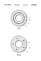
- FIG. 2is an enlarged cross-section on the line II--II of FIG. 1 showing a first preferred embodiment of the invention
- FIG. 3is an enlarged cross-section on the line II--II of FIG. 1 showing a second preferred embodiment of the invention
- FIG. 4is an enlarged cross-section on the line II--II of FIG. 1 showing a third preferred embodiment
- FIG. 5is an enlarged cross-section on the line II--II of FIG. 1 showing a fourth preferred embodiment
- FIG. 6is an enlarged cross-section on the line VI--VI of FIG. 1 showing the stopping flange of the electrosurgery probe according to the invention.
- FIG. 1there is shown an auxiliary tubing probe 1 according to the invention, for converting a monopolar electrosurgery probe 3 shown in dotted lines into a bipolar electrosurgery probe 5.
- the monopolar electrosurgery probe 3preferably consists of a laparoscopic electrode or an electric conducting cannula.
- the monopolar electrosurgery probe 3has a main electrode 7 at one end having the shape of a hockey stick, and is electrically connected to a power source 9.
- the monopolar electrosurgery probe 3also has a stopping flange 11, for stopping its insertion in the auxiliary probe 1. That stopping flange 11 is star-shaped as shown on FIG. 6.
- the auxiliary tubing probe 1comprises an inner electrically insulated tube 13 in which the monopolar electrosurgery probe 3 is slidably inserted.
- the inner electrically insulated tube 13has a first and a second opposite ends 15 and 17.
- the insulated tube 13preferably consists of polycarbonate. It may also consist of any material acting as an electric insulator.
- At least one electric conductor 19extends externally over and along the inner insulated tube 13.
- This electric conductor 19has a first extremity 21 and a second extremity 23.
- the auxiliary tubing probe 1also comprises an auxiliary electrode 25 projecting forward from the first end 15 of the inner tube 13.
- the auxiliary electrode 25preferably has the shape of a J-hook, but may also have the shape of a needle, a hockey stick, a L-hook or a spatula, as is known in this art.
- the auxiliary electrode 25is connected to the first extremity 21 of the at least one electric conductor 19. When the monopolar electrosurgery probe 3 has been inserted in the auxiliary probe 1, the auxiliary electrode 25 is adjacent to the main electrode 7 of the monopolar electrosurgery probe 3.
- the auxiliary tubing probe 1further comprises an outer electric insulator 27 covering the electrical conductor 19 from its first extremity 21 to its second extremity 23.
- the outer electric insulator 27also covers the inner electrically insulated tube 13.
- the outer electric insulator 27preferably consists of polycarbonate. It may also consist of any material which is biocompatible and may act as an electrical insulator.
- the auxiliary probe 1also has attachment means for retaining the auxiliary probe 1 on the monopolar electrosurgery probe 3.
- the attachment meanscan be of any type but preferably comprises a pair of O-rings 29 mounted in small grooves made in the inner auxiliary probe 1 near the second end 15 of the inner tube 13.
- the attachment meansmay also consist in snug-fitting the auxiliary tubing probe 1 over the monopolar electrosurgery probe 3.
- the auxiliary probefurther comprises a disengaging flange 31 adjacent to the second end 17 of the inner tube 13, used to separate the auxiliary probe 1 from the monopolar electrosurgery probe 3.
- the electrical conductor 19is a metallic weaver 23 enveloping the inner insulated tube 13.
- the metallic weaver disposed in such a manneracts as a Faraday cage surrounding the monopolar electrosurgery probe 3. Such a disposition improves the grounding effect of the auxiliary tubing probe 1.
- the at least one electrical conductor 19is inserted in grooves 25 made in the inner electrically insulated tube 13.
- the outer electric insulator 27 and the inner electrically insulated tube 13are combined in a single tube into which the at least one electric conductor 19 is inserted.
- a first connecting pathmay consist in connecting the monopolar electrosurgery probe to the power source 9, and to use the auxiliary electrosurgery probe 1 as a floating ground.
- a second connecting pathmay be to connect the auxiliary electrosurgery probe 1 to the power source 9 and to use the monopolar electrosurgery probe as a floating ground.
- a third connecting pathmay consist in connecting the monopolar electrosurgery probe 3 and the auxiliary electrosurgery probe 1 to the power source 9.
- the auxiliary tubing probeeasily and temporarily transforms a monopolar electrosurgery probe in a bipolar electrosurgery probe which is electrically safe for both the patient and the surgeon.
Landscapes
- Health & Medical Sciences (AREA)
- Surgery (AREA)
- Engineering & Computer Science (AREA)
- Life Sciences & Earth Sciences (AREA)
- Biomedical Technology (AREA)
- Molecular Biology (AREA)
- Nuclear Medicine, Radiotherapy & Molecular Imaging (AREA)
- Plasma & Fusion (AREA)
- Physics & Mathematics (AREA)
- Heart & Thoracic Surgery (AREA)
- Medical Informatics (AREA)
- Otolaryngology (AREA)
- Animal Behavior & Ethology (AREA)
- General Health & Medical Sciences (AREA)
- Public Health (AREA)
- Veterinary Medicine (AREA)
- Surgical Instruments (AREA)
- Endoscopes (AREA)
- Measuring Leads Or Probes (AREA)
Abstract
Description
a) Field of the Invention
The present invention relates to an auxiliary tubing probe for converting a monopolar electrosurgery probe into a bipolar electrosurgery probe. The expression "electrosurgery probe" as used herein is intended to include all the probes that are or can be used in the medical field, and more particularly for laparoscopy and endoscopy.
b) Description of the Prior Art
Monopolar electrosurgery probes are widely used in laparoscopy and endoscopy, essentially for cutting and healing purposes. They comprise an electrical conducting cannula having one extremity connected to a power source and a second extremity ended by an emitting electrode.
Because of their single polarity, a grounding element is required under or near the patient. Since the grounding element and the emitting electrode are separated by parts of the patient's body, the electric current emitted by the emitting electrode traverses those body parts.
The electric current sometimes causes damages to these body parts, damages that could be avoided by having a nearer grounding element.
It is therefore the object of the present invention to provide means for easily and temporarily transforming a monopolar electrosurgery probe into a bipolar electrosurgery probe, which thanks to its bipolarity is electrically safer for the patient and the surgeon.
In accordance with the present invention, this object is achieved with an auxiliary tubing probe for converting a monopolar electrosurgery probe into a bipolar electrosurgery probe. The monopolar electrosurgery probe which is of a conventional structure, has a main electrode at one end which is electrically connectable to a power source which generates electricity. The auxiliary probe according to the invention comprises:
an inner electrically insulated tube in which the monopolar electrosurgery probe may be slidably inserted, the inner tube having first and second ends;
at least one electric conductor extending externally over and along the inner insulated tube, the electric conductor having a first and a second extremity;
an auxiliary electrode projecting forward from the first end of the inner tube and being connected to the first extremity of the at least one electric conductor, the auxiliary electrode being adjacent to the main electrode when the monopolar electrosurgery probe has been inserted in the auxiliary probe; and
an outer electric insulator covering the electric conductor from the first extremity to the second extremity, whereby, insertion of the auxiliary probe over the monopolar electrosurgery probe and electricity going through said auxiliary electrosurgery probe and monopolar electrosurgery probe converts the monopolar electrosurgery probe into a bipolar electrosurgery probe.
Preferably, the auxiliary tubing probe comprises attachment means for retaining it on the monopolar electrosurgery probe.
Preferably also, the auxiliary tubing probe comprises a disengaging flange adjacent to the second end of the inner tube for use to separate it from the monopolar electrosurgery probe.
As aforesaid, the monopolar electrosurgery probe can be a laparoscopic monopolar electrode. It can also be any other kind of electrode used in the medical field.
The objects, advantages and other features of the present invention will become more apparent upon reading of the following non restrictive description of preferred embodiments thereof, given for the purpose of exemplification only, with reference to the accompanying drawings.
FIG. 1 is an enlarged cross-sectional side elevation view of a conventional monopolar electrosurgery probe shown in dotted lines and provided with an auxiliary tubing probe according to the invention for use to make it bipolar;
FIG. 2 is an enlarged cross-section on the line II--II of FIG. 1 showing a first preferred embodiment of the invention;
FIG. 3 is an enlarged cross-section on the line II--II of FIG. 1 showing a second preferred embodiment of the invention;
FIG. 4 is an enlarged cross-section on the line II--II of FIG. 1 showing a third preferred embodiment;
FIG. 5 is an enlarged cross-section on the line II--II of FIG. 1 showing a fourth preferred embodiment;
FIG. 6 is an enlarged cross-section on the line VI--VI of FIG. 1 showing the stopping flange of the electrosurgery probe according to the invention.
Referring to FIG. 1, there is shown an auxiliary tubing probe 1 according to the invention, for converting amonopolar electrosurgery probe 3 shown in dotted lines into a bipolar electrosurgery probe 5.
Themonopolar electrosurgery probe 3 preferably consists of a laparoscopic electrode or an electric conducting cannula. Themonopolar electrosurgery probe 3 has amain electrode 7 at one end having the shape of a hockey stick, and is electrically connected to a power source 9. Themonopolar electrosurgery probe 3 also has a stoppingflange 11, for stopping its insertion in the auxiliary probe 1. That stoppingflange 11 is star-shaped as shown on FIG. 6.
The auxiliary tubing probe 1 comprises an inner electrically insulatedtube 13 in which themonopolar electrosurgery probe 3 is slidably inserted. The inner electrically insulatedtube 13 has a first and asecond opposite ends tube 13 preferably consists of polycarbonate. It may also consist of any material acting as an electric insulator.
As shown on FIG. 2, at least oneelectric conductor 19 extends externally over and along the inner insulatedtube 13. Thiselectric conductor 19 has afirst extremity 21 and asecond extremity 23.
The auxiliary tubing probe 1 also comprises anauxiliary electrode 25 projecting forward from thefirst end 15 of theinner tube 13. Theauxiliary electrode 25 preferably has the shape of a J-hook, but may also have the shape of a needle, a hockey stick, a L-hook or a spatula, as is known in this art.
Theauxiliary electrode 25 is connected to thefirst extremity 21 of the at least oneelectric conductor 19. When themonopolar electrosurgery probe 3 has been inserted in the auxiliary probe 1, theauxiliary electrode 25 is adjacent to themain electrode 7 of themonopolar electrosurgery probe 3.
The auxiliary tubing probe 1 further comprises an outerelectric insulator 27 covering theelectrical conductor 19 from itsfirst extremity 21 to itssecond extremity 23. The outerelectric insulator 27 also covers the inner electrically insulatedtube 13. The outerelectric insulator 27 preferably consists of polycarbonate. It may also consist of any material which is biocompatible and may act as an electrical insulator.
The auxiliary probe 1 also has attachment means for retaining the auxiliary probe 1 on themonopolar electrosurgery probe 3. The attachment means can be of any type but preferably comprises a pair of O-rings 29 mounted in small grooves made in the inner auxiliary probe 1 near thesecond end 15 of theinner tube 13. The attachment means may also consist in snug-fitting the auxiliary tubing probe 1 over themonopolar electrosurgery probe 3.
The auxiliary probe further comprises a disengagingflange 31 adjacent to thesecond end 17 of theinner tube 13, used to separate the auxiliary probe 1 from themonopolar electrosurgery probe 3.
In a second embodiment of the invention, shown on FIG. 4, theelectrical conductor 19 is ametallic weaver 23 enveloping the inner insulatedtube 13. The metallic weaver disposed in such a manner acts as a Faraday cage surrounding themonopolar electrosurgery probe 3. Such a disposition improves the grounding effect of the auxiliary tubing probe 1.
In a third embodiment of the invention, shown on FIG. 3, the at least oneelectrical conductor 19 is inserted ingrooves 25 made in the inner electrically insulatedtube 13.
In a fourth embodiment of the invention, shown on FIG. 5, the outerelectric insulator 27 and the inner electrically insulatedtube 13 are combined in a single tube into which the at least oneelectric conductor 19 is inserted.
In use, a first connecting path may consist in connecting the monopolar electrosurgery probe to the power source 9, and to use the auxiliary electrosurgery probe 1 as a floating ground. A second connecting path may be to connect the auxiliary electrosurgery probe 1 to the power source 9 and to use the monopolar electrosurgery probe as a floating ground. A third connecting path may consist in connecting themonopolar electrosurgery probe 3 and the auxiliary electrosurgery probe 1 to the power source 9.
In operation, when the auxiliary tubing probe 1 is inserted over themonopolar electrosurgery probe 3 and when electricity circulates in theprobes 1 and 3, themonopolar electrosurgery probe 3 is converted into a bipolar electrosurgery probe 5.
The auxiliary tubing probe easily and temporarily transforms a monopolar electrosurgery probe in a bipolar electrosurgery probe which is electrically safe for both the patient and the surgeon.
Although the present invention has been explained hereinabove by way of preferred embodiments thereof, it should be pointed out that any modifications to these preferred embodiments, within the scope of the appended claims are not deemed to change or alter the nature and scope of the present invention.
Claims (18)
1. An auxiliary tubing probe for converting a monopolar electrosurgery probe into a bipolar electrosurgery probe, said monopolar electrosurgery probe having a main electrode at one end which is electrically connectable to a power source, said power source generating electricity, said auxiliary probe comprising:
an inner electrically insulated tube in which said monopolar electrosurgery probe may be slidably inserted, said inner tube having first and second opposite ends;
at least one electric conductor extending externally over and along said inner insulated tube, said electric conductor having a first and a second extremity;
an auxiliary electrode projecting forward from the first end of said inner tube and being connected to the first extremity of said at least one electric conductor, said auxiliary electrode being adjacent to said main electrode when said monopolar electrosurgery probe has been inserted in said auxiliary probe;
an outer electric insulator covering said at least one electric conductor from said first extremity to said second extremity; and
attachment means for retaining said auxiliary probe on said monopolar electrosurgery probe,
whereby, insertion of said auxiliary probe over the monopolar electrosurgery probe and electricity going through said auxiliary electrosurgery probe and monopolar electrosurgery probe converts said monopolar electrosurgery probe into a bipolar electrosurgery probe.
2. An auxiliary probe according to claim 1 further comprising a disengaging flange connected adjacent to the second end of the inner tube for use to separate said auxiliary probe from said monopolar electrosurgery probe.
3. An auxiliary probe according to claim 1 wherein said attachment means are a pair of O-rings mounted in small grooves in an inner portion of said auxiliary probe near the second end of said inner tube.
4. An auxiliary tubing probe for converting a monopolar electrosurgery probe into a bipolar electrosurgery probe, said monopolar electrosurgery probe having a main electrode at one end which is electrically connectable to a power source, said power source generating electricity, said auxiliary probe comprising:
an inner electrically insulated tube in which said monopolar electrosurgery probe may be slidably inserted, said inner tube having first and second opposite ends;
at least one electric conductor extending externally over and along said inner insulated tube, said electric conductor having a first and a second extremity;
an auxiliary electrode projecting forward from the first end of said inner tube and being connected to the first extremity of said at least one electric conductor, said auxiliary electrode being adjacent to said main electrode when said monopolar electrosurgery probe has been inserted in said auxiliary probe;
an outer electric insulator covering said at least one electric conductor from said first extremity to said second extremity; and
a disengaging flange connected adjacent to the second end of the inner tube for use to separate said auxiliary probe from said monopolar electrosurgery probe,
whereby, insertion of said auxiliary probe over the monopolar electrosurgery probe and electricity going through said auxiliary electrosurgery probe and monopolar electrosurgery probe converts said monopolar electrosurgery probe into a bipolar electrosurgery probe.
5. An auxiliary tubing probe for converting a monopolar electrosurgery probe into a bipolar electrosurgery probe, said monopolar electrosurgery probe having a main electrode at one end which is electrically connectable to a power source, said power source generating electricity, said auxiliary probe comprising:
an inner electrically insulated tube in which said monopolar electrosurgery probe may be slidably inserted, said inner tube having first and second opposite ends;
at least one electric conductor extending externally over and along said inner insulated tube, said electric conductor having a first and a second extremity and consisting of a metallic weaver enveloping said inner insulated tube;
an auxiliary electrode projecting forward from the first end of said inner tube and being connected to the first extremity of said at least one electric conductor, said auxiliary electrode being adjacent to said main electrode when said monopolar electrosurgery probe has been inserted in said auxiliary probe; and
an outer electric insulator covering said at least one electric conductor from said first extremity to said second extremity, whereby, insertion of said auxiliary probe over the monopolar electrosurgery probe and electricity going through said auxiliary electrosurgery probe and monopolar electrosurgery probe converts said monopolar electrosurgery probe into a bipolar electrosurgery probe.
6. An auxiliary probe according to claim 5 wherein said auxiliary electrode has the shape of a J-hook and said main electrode has the shape of a hockey stick.
7. An auxiliary probe according to claim 5 wherein said inner insulated tube and said outer electric insulator are made of polycarbonate.
8. An auxiliary probe according to claim 5 wherein the first extremity of said at least one electric conductor projects outwardly from said first end of said inner electrically insulated tube.
9. An auxiliary probe according to claim 5 further comprising attachment means for retaining said auxiliary probe on said monopolar electrosurgery probe.
10. An auxiliary probe according to claim 9 further comprising a disengaging flange connected adjacent to the second end of the inner tube for use to separate said auxiliary probe from said monopolar electrosurgery probe.
11. An auxiliary probe according to claim 9 wherein said attachment means are a pair of O-rings mounted in small grooves made in an inner portion of said auxiliary probe near the second end of said inner tube.
12. The combination of an auxiliary tubing probe with a monopolar electro-surgery probe, said monopolar electrosurgery probe having a main electrode at one end which is electrically connectable to a power source, said power source generating electricity, said auxiliary probe comprising:
an inner electrically insulated tube in which said monopolar electrosurgery probe is slidably inserted, said inner tube having first and second opposite ends;
at least one electric conductor extending externally over and along said inner insulated tube, said electric conductor having a first and a second extremity and consisting of a metallic weaver enveloping said inner insulated tube;
an auxiliary electrode projecting forward from the first end of said inner tube and being connected to the first extremity of said at least one electric conductor, said auxiliary electrode being adjacent to said main electrode when said monopolar electrosurgery probe is inserted in said auxiliary probe; and
an outer insulator covering said at least one electric conductor from said first extremity to said second extremity,
whereby, insertion of said auxiliary probe over the monopolar electrosurgery probe, and electricity going through said auxiliary electrosurgery probe and monopolar electrosurgery probe converts said monopolar electrosurgery probe into a bipolar electrosurgery probe.
13. The combination according to claim 12 wherein said monopolar electrosurgery probe has a stopping flange for stopping its insertion in said auxiliary probe.
14. The combination according to claim 13 wherein said stopping flange is star-shaped.
15. The combination according to claim 12 wherein said monopolar electrosurgery probe is a laparoscopic monopolar electrode.
16. The combination according to claim 15 wherein said laparoscopic monopolar electrode is an electricity conducting cannula.
17. The combination according to claim 12 wherein:
said monopolar electrosurgery probe is a laparoscopic monopolar electrode;
said auxiliary electrode has the shape of a J-hook and said main electrode has the shape of a hockey stick;
said inner insulated tube and said outer electrical insulator are made of polycarbonate; and
said monopolar electrosurgery probe has a star-shaped stopping flange.
18. The combination according to claim 17 further comprising:
a pair of O-rings mounted in small grooves made in an inner portion of said auxiliary probe near the second end of the inner tube; and
a disengaging flange connected adjacent to the second end of said inner tube for use to separate said auxiliary probe from said monopolar electrosurgery probe.
Priority Applications (2)
| Application Number | Priority Date | Filing Date | Title |
|---|---|---|---|
| US08/187,476US5409487A (en) | 1994-01-28 | 1994-01-28 | Auxiliary tubing probe |
| CA002141661ACA2141661C (en) | 1994-01-28 | 1995-02-01 | Auxiliary tubing probe |
Applications Claiming Priority (2)
| Application Number | Priority Date | Filing Date | Title |
|---|---|---|---|
| US08/187,476US5409487A (en) | 1994-01-28 | 1994-01-28 | Auxiliary tubing probe |
| CA002141661ACA2141661C (en) | 1994-01-28 | 1995-02-01 | Auxiliary tubing probe |
Publications (1)
| Publication Number | Publication Date |
|---|---|
| US5409487Atrue US5409487A (en) | 1995-04-25 |
Family
ID=25677764
Family Applications (1)
| Application Number | Title | Priority Date | Filing Date |
|---|---|---|---|
| US08/187,476Expired - Fee RelatedUS5409487A (en) | 1994-01-28 | 1994-01-28 | Auxiliary tubing probe |
Country Status (2)
| Country | Link |
|---|---|
| US (1) | US5409487A (en) |
| CA (1) | CA2141661C (en) |
Cited By (16)
| Publication number | Priority date | Publication date | Assignee | Title |
|---|---|---|---|---|
| US5957884A (en)* | 1995-02-10 | 1999-09-28 | Enable Medical Corporation | System for morselating and removing tissue from a patient |
| US5989249A (en)* | 1996-04-29 | 1999-11-23 | Kirwan Surgical Products, Inc. | Bipolar suction coagulator |
| US6078830A (en)* | 1997-10-01 | 2000-06-20 | Ep Technologies, Inc. | Molded catheter distal end assembly and process for the manufacture thereof |
| US20020165541A1 (en)* | 2001-04-20 | 2002-11-07 | Whitman Michael P. | Bipolar or ultrasonic surgical device |
| US20040097958A1 (en)* | 2002-07-31 | 2004-05-20 | Whitman Michael P. | Orifice introducer device |
| US7951071B2 (en) | 1999-06-02 | 2011-05-31 | Tyco Healthcare Group Lp | Moisture-detecting shaft for use with an electro-mechanical surgical device |
| US8025199B2 (en) | 2004-02-23 | 2011-09-27 | Tyco Healthcare Group Lp | Surgical cutting and stapling device |
| US8357144B2 (en) | 1999-06-02 | 2013-01-22 | Covidien, LP | Electro-mechanical surgical device |
| EP2884928A4 (en)* | 2012-08-15 | 2016-04-20 | Thermedical Inc | Low profile fluid enhanced ablation therapy devices and methods |
| US9445861B2 (en) | 2011-04-12 | 2016-09-20 | Thermedical, Inc. | Methods and devices for controlling ablation therapy |
| US9610396B2 (en) | 2013-03-15 | 2017-04-04 | Thermedical, Inc. | Systems and methods for visualizing fluid enhanced ablation therapy |
| US9743984B1 (en) | 2016-08-11 | 2017-08-29 | Thermedical, Inc. | Devices and methods for delivering fluid to tissue during ablation therapy |
| US10058385B2 (en) | 2013-03-15 | 2018-08-28 | Thermedical, Inc. | Methods and devices for fluid enhanced microwave ablation therapy |
| JP2020512049A (en)* | 2016-12-23 | 2020-04-23 | ゼニオス アーゲー | A cannula along which the wire extends |
| US11083871B2 (en) | 2018-05-03 | 2021-08-10 | Thermedical, Inc. | Selectively deployable catheter ablation devices |
| US11918277B2 (en) | 2018-07-16 | 2024-03-05 | Thermedical, Inc. | Inferred maximum temperature monitoring for irrigated ablation therapy |
Citations (9)
| Publication number | Priority date | Publication date | Assignee | Title |
|---|---|---|---|---|
| US33925A (en)* | 1861-12-17 | Improvement in fastenings for shoulder-straps | ||
| US3906955A (en)* | 1974-05-06 | 1975-09-23 | Richard R Roberts | Surgical cauterizing tool having suction means |
| US4608986A (en)* | 1984-10-01 | 1986-09-02 | Cordis Corporation | Pacing lead with straight wire conductors |
| US5035695A (en)* | 1987-11-30 | 1991-07-30 | Jaroy Weber, Jr. | Extendable electrocautery surgery apparatus and method |
| US5092333A (en)* | 1987-06-25 | 1992-03-03 | Kouji Tsuchida | Catheter accommodating electrical wires |
| US5197963A (en)* | 1991-12-02 | 1993-03-30 | Everest Medical Corporation | Electrosurgical instrument with extendable sheath for irrigation and aspiration |
| US5277696A (en)* | 1991-11-19 | 1994-01-11 | Delma Elektro- Und Medizinische Apparatebau Gesellschaft Mbh | Medical high frequency coagulation instrument |
| US5304176A (en)* | 1990-05-25 | 1994-04-19 | Phillips Edward H | Tool for laparoscopic surgery |
| US5312401A (en)* | 1991-07-10 | 1994-05-17 | Electroscope, Inc. | Electrosurgical apparatus for laparoscopic and like procedures |
- 1994
- 1994-01-28USUS08/187,476patent/US5409487A/ennot_activeExpired - Fee Related
- 1995
- 1995-02-01CACA002141661Apatent/CA2141661C/ennot_activeExpired - Fee Related
Patent Citations (9)
| Publication number | Priority date | Publication date | Assignee | Title |
|---|---|---|---|---|
| US33925A (en)* | 1861-12-17 | Improvement in fastenings for shoulder-straps | ||
| US3906955A (en)* | 1974-05-06 | 1975-09-23 | Richard R Roberts | Surgical cauterizing tool having suction means |
| US4608986A (en)* | 1984-10-01 | 1986-09-02 | Cordis Corporation | Pacing lead with straight wire conductors |
| US5092333A (en)* | 1987-06-25 | 1992-03-03 | Kouji Tsuchida | Catheter accommodating electrical wires |
| US5035695A (en)* | 1987-11-30 | 1991-07-30 | Jaroy Weber, Jr. | Extendable electrocautery surgery apparatus and method |
| US5304176A (en)* | 1990-05-25 | 1994-04-19 | Phillips Edward H | Tool for laparoscopic surgery |
| US5312401A (en)* | 1991-07-10 | 1994-05-17 | Electroscope, Inc. | Electrosurgical apparatus for laparoscopic and like procedures |
| US5277696A (en)* | 1991-11-19 | 1994-01-11 | Delma Elektro- Und Medizinische Apparatebau Gesellschaft Mbh | Medical high frequency coagulation instrument |
| US5197963A (en)* | 1991-12-02 | 1993-03-30 | Everest Medical Corporation | Electrosurgical instrument with extendable sheath for irrigation and aspiration |
Cited By (49)
| Publication number | Priority date | Publication date | Assignee | Title |
|---|---|---|---|---|
| US5957884A (en)* | 1995-02-10 | 1999-09-28 | Enable Medical Corporation | System for morselating and removing tissue from a patient |
| US6007512A (en)* | 1995-02-10 | 1999-12-28 | Enable Medical Corporation | Apparatus and method for morselating and removing tissue from a patient |
| US6036681A (en)* | 1995-02-10 | 2000-03-14 | Enable Medical Corporation | Apparatus and method for morselating and removing tissue from a patient |
| US5989249A (en)* | 1996-04-29 | 1999-11-23 | Kirwan Surgical Products, Inc. | Bipolar suction coagulator |
| US6078830A (en)* | 1997-10-01 | 2000-06-20 | Ep Technologies, Inc. | Molded catheter distal end assembly and process for the manufacture thereof |
| US6456863B1 (en) | 1997-10-01 | 2002-09-24 | Ep Technologies, Inc. | Molded catheter distal end assembly and process for the manufacture thereof |
| US9113847B2 (en) | 1999-06-02 | 2015-08-25 | Covidien Lp | Electro-mechanical surgical device |
| US9033868B2 (en) | 1999-06-02 | 2015-05-19 | Covidien Lp | Couplings for interconnecting components of an electro-mechanical surgical device |
| US9662514B2 (en) | 1999-06-02 | 2017-05-30 | Covidien Lp | Bipolar or ultrasonic surgical device |
| US7951071B2 (en) | 1999-06-02 | 2011-05-31 | Tyco Healthcare Group Lp | Moisture-detecting shaft for use with an electro-mechanical surgical device |
| US10335143B2 (en) | 1999-06-02 | 2019-07-02 | Covidien Lp | Surgical cutting and stapling device |
| US9364200B2 (en) | 1999-06-02 | 2016-06-14 | Covidien Lp | Electro-mechanical surgical device |
| US8357144B2 (en) | 1999-06-02 | 2013-01-22 | Covidien, LP | Electro-mechanical surgical device |
| US9247940B2 (en) | 1999-06-02 | 2016-02-02 | Covidien Lp | Surgical cutting and stapling device |
| US8628467B2 (en) | 1999-06-02 | 2014-01-14 | Covidien Lp | Moisture-detecting shaft for use with an electro-mechanical surgical device |
| US10314659B2 (en) | 1999-06-02 | 2019-06-11 | Covidien Lp | Electro-mechanical surgical device |
| US8292888B2 (en) | 2001-04-20 | 2012-10-23 | Tyco Healthcare Group Lp | Bipolar or ultrasonic surgical device |
| US8845665B2 (en) | 2001-04-20 | 2014-09-30 | Covidien Lp | Bipolar or ultrasonic surgical device |
| US8523890B2 (en) | 2001-04-20 | 2013-09-03 | Covidien Lp | Bipolar or ultrasonic surgical device |
| US20020165541A1 (en)* | 2001-04-20 | 2002-11-07 | Whitman Michael P. | Bipolar or ultrasonic surgical device |
| US8814785B2 (en) | 2002-07-31 | 2014-08-26 | Covidien Lp | Orifice introducer device |
| US20040097958A1 (en)* | 2002-07-31 | 2004-05-20 | Whitman Michael P. | Orifice introducer device |
| US9554824B2 (en) | 2002-07-31 | 2017-01-31 | Covidien Lp | Orifice introducer device |
| US7874981B2 (en) | 2002-07-31 | 2011-01-25 | Tyco Healthcare Group Lp | Orifice introducer device |
| US11219452B2 (en) | 2004-02-23 | 2022-01-11 | Covidien Lp | Surgical cutting and stapling device |
| US8025199B2 (en) | 2004-02-23 | 2011-09-27 | Tyco Healthcare Group Lp | Surgical cutting and stapling device |
| US10548654B2 (en) | 2011-04-12 | 2020-02-04 | Thermedical, Inc. | Devices and methods for remote temperature monitoring in fluid enhanced ablation therapy |
| US10881443B2 (en) | 2011-04-12 | 2021-01-05 | Thermedical, Inc. | Devices and methods for shaping therapy in fluid enhanced ablation |
| US9877768B2 (en) | 2011-04-12 | 2018-01-30 | Thermedical, Inc. | Methods and devices for heating fluid in fluid enhanced ablation therapy |
| US9937000B2 (en) | 2011-04-12 | 2018-04-10 | Thermedical, Inc. | Methods and devices for controlling ablation therapy |
| US11950829B2 (en) | 2011-04-12 | 2024-04-09 | Thermedical, Inc. | Methods and devices for use of degassed fluids with fluid enhanced ablation devices |
| US11871979B2 (en) | 2011-04-12 | 2024-01-16 | Thermedical, Inc. | Methods and devices for controlling ablation therapy |
| US10307201B2 (en) | 2011-04-12 | 2019-06-04 | Thermedical, Inc. | Methods and devices for use of degassed fluids with fluid enhanced ablation devices |
| US9730748B2 (en) | 2011-04-12 | 2017-08-15 | Thermedical, Inc. | Devices and methods for shaping therapy in fluid enhanced ablation |
| US11583330B2 (en) | 2011-04-12 | 2023-02-21 | Thermedical, Inc. | Devices and methods for remote temperature monitoring in fluid enhanced ablation therapy |
| US10448987B2 (en) | 2011-04-12 | 2019-10-22 | Thermedical, Inc. | Methods and devices for controlling ablation therapy |
| US9445861B2 (en) | 2011-04-12 | 2016-09-20 | Thermedical, Inc. | Methods and devices for controlling ablation therapy |
| US11135000B2 (en) | 2011-04-12 | 2021-10-05 | Thermedical, Inc. | Methods and devices for use of degassed fluids with fluid enhanced ablation devices |
| EP2884928A4 (en)* | 2012-08-15 | 2016-04-20 | Thermedical Inc | Low profile fluid enhanced ablation therapy devices and methods |
| US10022176B2 (en) | 2012-08-15 | 2018-07-17 | Thermedical, Inc. | Low profile fluid enhanced ablation therapy devices and methods |
| US9610396B2 (en) | 2013-03-15 | 2017-04-04 | Thermedical, Inc. | Systems and methods for visualizing fluid enhanced ablation therapy |
| US10058385B2 (en) | 2013-03-15 | 2018-08-28 | Thermedical, Inc. | Methods and devices for fluid enhanced microwave ablation therapy |
| US11013555B2 (en) | 2016-08-11 | 2021-05-25 | Thermedical, Inc. | Devices and methods for delivering fluid to tissue during ablation therapy |
| US9743984B1 (en) | 2016-08-11 | 2017-08-29 | Thermedical, Inc. | Devices and methods for delivering fluid to tissue during ablation therapy |
| US12310651B2 (en) | 2016-08-11 | 2025-05-27 | Thermedical, Inc. | Devices and methods for delivering fluid to tissue during ablation therapy |
| JP2020512049A (en)* | 2016-12-23 | 2020-04-23 | ゼニオス アーゲー | A cannula along which the wire extends |
| US11590318B2 (en) | 2016-12-23 | 2023-02-28 | Xenios Ag | Cannula having a wire that extends along said cannula |
| US11083871B2 (en) | 2018-05-03 | 2021-08-10 | Thermedical, Inc. | Selectively deployable catheter ablation devices |
| US11918277B2 (en) | 2018-07-16 | 2024-03-05 | Thermedical, Inc. | Inferred maximum temperature monitoring for irrigated ablation therapy |
Also Published As
| Publication number | Publication date |
|---|---|
| CA2141661C (en) | 1999-01-19 |
| CA2141661A1 (en) | 1996-08-02 |
Similar Documents
| Publication | Publication Date | Title |
|---|---|---|
| US5409487A (en) | Auxiliary tubing probe | |
| US7763018B2 (en) | Cool-tip thermocouple including two-piece hub | |
| US8267934B2 (en) | Electrosurgical tool | |
| US7122035B2 (en) | Bipolar surgical forceps with argon plasma coagulation capability | |
| US6210409B1 (en) | Electrosurgical handpiece for treating tissue | |
| US7549990B2 (en) | Surgical scissors with argon plasma coagulation capability | |
| US7611511B2 (en) | Bipolar medical instrument and electrosurgical system comprising such an instrument | |
| US20220226039A1 (en) | Rf ablation systems and methods including a cannula with contacts or a connector | |
| US20040116923A1 (en) | Electrode arrangement for surgical instrument | |
| US12329445B2 (en) | RF ablation systems and methods using an integrated cannula and electrode | |
| CA2326155A1 (en) | Improved rf bipolar end effector for use in electrosurgical instruments | |
| US7273480B2 (en) | Composite material braided insulator | |
| US7118569B2 (en) | Bipolar resectoscope electrode | |
| US20230165630A1 (en) | System and method for tissue puncture | |
| US20160235462A1 (en) | System and Method for Plasma Sealing of Tissue | |
| US10543012B2 (en) | Ultrasonic surgical device with reduction in electrical interference | |
| WO2001054602A3 (en) | Electrosurgical wire knife | |
| HUP0001099A2 (en) | Electrosurgical device | |
| US20140031807A1 (en) | Electromagnetic Shielding For An Electrosurgical Unit | |
| WO2024054623A2 (en) | Methods and apparatus for performing medical procedures using radiofrequency energy | |
| US10052169B2 (en) | Shield for electrosurgical suction coagulator and kit including the same | |
| US20080065063A1 (en) | High-frequency endoscopic instrument | |
| JP5629434B2 (en) | Microwave surgical device | |
| CA2244076A1 (en) | Radio frequency dilator sheath |
Legal Events
| Date | Code | Title | Description |
|---|---|---|---|
| AS | Assignment | Owner name:YAB REVO-TECH INC., QUEBEC Free format text:ASSIGNMENT OF ASSIGNORS INTEREST;ASSIGNORS:JALBERT, FERNAND;BELAND, GERMAIN;REEL/FRAME:006849/0743 Effective date:19940122 | |
| AS | Assignment | Owner name:RD-CHUS INC., CANADA Free format text:ASSIGNMENT OF ASSIGNORS INTEREST;ASSIGNOR:YAB REVO-TECH INC.;REEL/FRAME:007978/0588 Effective date:19960515 | |
| FPAY | Fee payment | Year of fee payment:4 | |
| AS | Assignment | Owner name:YAB REVOTECH INC., CANADA Free format text:DECLARATION OF THE TRUSTEE OF RD-CHUS INC.;ASSIGNOR:RD-CHUS INC.;REEL/FRAME:013036/0152 Effective date:20020516 | |
| REMI | Maintenance fee reminder mailed | ||
| LAPS | Lapse for failure to pay maintenance fees | ||
| STCH | Information on status: patent discontinuation | Free format text:PATENT EXPIRED DUE TO NONPAYMENT OF MAINTENANCE FEES UNDER 37 CFR 1.362 | |
| FP | Lapsed due to failure to pay maintenance fee | Effective date:20030425 |