US5409479A - Method for closing tissue wounds using radiative energy beams - Google Patents
Method for closing tissue wounds using radiative energy beamsDownload PDFInfo
- Publication number
- US5409479A US5409479AUS07/934,167US93416792AUS5409479AUS 5409479 AUS5409479 AUS 5409479AUS 93416792 AUS93416792 AUS 93416792AUS 5409479 AUS5409479 AUS 5409479A
- Authority
- US
- United States
- Prior art keywords
- tissue
- optical energy
- recited
- energy
- duration
- Prior art date
- Legal status (The legal status is an assumption and is not a legal conclusion. Google has not performed a legal analysis and makes no representation as to the accuracy of the status listed.)
- Expired - Fee Related
Links
- 238000000034methodMethods0.000titleclaimsabstractdescription34
- 206010052428WoundDiseases0.000titledescription16
- 208000027418Wounds and injuryDiseases0.000titledescription16
- 230000003287optical effectEffects0.000claimsabstractdescription50
- 102000004169proteins and genesHuman genes0.000claimsabstractdescription11
- 108090000623proteins and genesProteins0.000claimsabstractdescription11
- 238000010438heat treatmentMethods0.000claimsabstractdescription5
- 238000010521absorption reactionMethods0.000claimsdescription10
- 210000002435tendonAnatomy0.000claimsdescription8
- 210000003101oviductAnatomy0.000claimsdescription6
- 210000001367arteryAnatomy0.000claimsdescription5
- 230000001112coagulating effectEffects0.000claimsdescription4
- 210000001177vas deferenAnatomy0.000claimsdescription4
- 230000000737periodic effectEffects0.000claimsdescription3
- 239000000835fiberSubstances0.000abstractdescription17
- 230000004044responseEffects0.000abstractdescription6
- 239000003364biologic glueSubstances0.000abstractdescription5
- 230000000694effectsEffects0.000abstractdescription3
- 230000000266injurious effectEffects0.000abstractdescription3
- 230000001105regulatory effectEffects0.000abstract1
- 210000001519tissueAnatomy0.000description138
- 238000003466weldingMethods0.000description11
- 230000003902lesionEffects0.000description10
- 239000000126substanceSubstances0.000description10
- 239000013307optical fiberSubstances0.000description9
- XLYOFNOQVPJJNP-UHFFFAOYSA-NwaterSubstancesOXLYOFNOQVPJJNP-UHFFFAOYSA-N0.000description7
- 229910019655synthetic inorganic crystalline materialInorganic materials0.000description6
- 230000008439repair processEffects0.000description5
- 230000006870functionEffects0.000description4
- 230000008569processEffects0.000description4
- 239000000523sampleSubstances0.000description4
- 230000005540biological transmissionEffects0.000description3
- 239000008280bloodSubstances0.000description3
- 210000004369bloodAnatomy0.000description3
- 230000000994depressogenic effectEffects0.000description3
- 238000010586diagramMethods0.000description3
- 239000003550markerSubstances0.000description3
- 238000012986modificationMethods0.000description3
- 230000004048modificationEffects0.000description3
- JNDMLEXHDPKVFC-UHFFFAOYSA-Naluminum;oxygen(2-);yttrium(3+)Chemical compound[O-2].[O-2].[O-2].[Al+3].[Y+3]JNDMLEXHDPKVFC-UHFFFAOYSA-N0.000description2
- 150000001413amino acidsChemical class0.000description2
- 230000015271coagulationEffects0.000description2
- 238000005345coagulationMethods0.000description2
- 230000001427coherent effectEffects0.000description2
- 238000001816coolingMethods0.000description2
- 230000001351cycling effectEffects0.000description2
- 210000001035gastrointestinal tractAnatomy0.000description2
- 230000035876healingEffects0.000description2
- CPBQJMYROZQQJC-UHFFFAOYSA-Nhelium neonChemical compound[He].[Ne]CPBQJMYROZQQJC-UHFFFAOYSA-N0.000description2
- 150000002500ionsChemical class0.000description2
- 229910052743kryptonInorganic materials0.000description2
- DNNSSWSSYDEUBZ-UHFFFAOYSA-Nkrypton atomChemical compound[Kr]DNNSSWSSYDEUBZ-UHFFFAOYSA-N0.000description2
- 238000013021overheatingMethods0.000description2
- 230000001681protective effectEffects0.000description2
- 238000005086pumpingMethods0.000description2
- 229910001220stainless steelInorganic materials0.000description2
- 230000002792vascularEffects0.000description2
- 238000012795verificationMethods0.000description2
- 230000000007visual effectEffects0.000description2
- 229910019901yttrium aluminum garnetInorganic materials0.000description2
- 102000008186CollagenHuman genes0.000description1
- 108010035532CollagenProteins0.000description1
- 241001269524DuraSpecies0.000description1
- 206010061218InflammationDiseases0.000description1
- 229910052779NeodymiumInorganic materials0.000description1
- 206010072170Skin woundDiseases0.000description1
- 208000002847Surgical WoundDiseases0.000description1
- 230000003213activating effectEffects0.000description1
- 230000006978adaptationEffects0.000description1
- 238000013459approachMethods0.000description1
- 230000031018biological processes and functionsEffects0.000description1
- 230000015572biosynthetic processEffects0.000description1
- 230000000903blocking effectEffects0.000description1
- 210000000845cartilageAnatomy0.000description1
- 229920001436collagenPolymers0.000description1
- 238000012937correctionMethods0.000description1
- 238000005520cutting processMethods0.000description1
- 230000003247decreasing effectEffects0.000description1
- 239000008367deionised waterSubstances0.000description1
- 229910021641deionized waterInorganic materials0.000description1
- 230000001934delayEffects0.000description1
- 230000000881depressing effectEffects0.000description1
- 230000006866deteriorationEffects0.000description1
- 239000006185dispersionSubstances0.000description1
- 238000010304firingMethods0.000description1
- 230000002209hydrophobic effectEffects0.000description1
- 208000015181infectious diseaseDiseases0.000description1
- 230000004054inflammatory processEffects0.000description1
- 238000003780insertionMethods0.000description1
- 230000037431insertionEffects0.000description1
- 238000002955isolationMethods0.000description1
- 238000005304joiningMethods0.000description1
- 238000000960laser coolingMethods0.000description1
- 238000002430laser surgeryMethods0.000description1
- 230000000670limiting effectEffects0.000description1
- 230000033001locomotionEffects0.000description1
- 239000000463materialSubstances0.000description1
- 238000005259measurementMethods0.000description1
- 230000005055memory storageEffects0.000description1
- 238000012544monitoring processMethods0.000description1
- QEFYFXOXNSNQGX-UHFFFAOYSA-Nneodymium atomChemical compound[Nd]QEFYFXOXNSNQGX-UHFFFAOYSA-N0.000description1
- 230000000644propagated effectEffects0.000description1
- 230000005855radiationEffects0.000description1
- 230000002829reductive effectEffects0.000description1
- 230000010076replicationEffects0.000description1
- 230000001850reproductive effectEffects0.000description1
- 230000037390scarringEffects0.000description1
- 210000003786scleraAnatomy0.000description1
- 238000007493shaping processMethods0.000description1
- 210000004872soft tissueAnatomy0.000description1
- 238000001228spectrumMethods0.000description1
- 238000001356surgical procedureMethods0.000description1
- 239000003356suture materialSubstances0.000description1
- 230000017423tissue regenerationEffects0.000description1
- 210000003454tympanic membraneAnatomy0.000description1
- 210000003462veinAnatomy0.000description1
Images


Classifications
- A—HUMAN NECESSITIES
- A61—MEDICAL OR VETERINARY SCIENCE; HYGIENE
- A61B—DIAGNOSIS; SURGERY; IDENTIFICATION
- A61B18/00—Surgical instruments, devices or methods for transferring non-mechanical forms of energy to or from the body
- A61B18/18—Surgical instruments, devices or methods for transferring non-mechanical forms of energy to or from the body by applying electromagnetic radiation, e.g. microwaves
- A61B18/20—Surgical instruments, devices or methods for transferring non-mechanical forms of energy to or from the body by applying electromagnetic radiation, e.g. microwaves using laser
- A61B18/22—Surgical instruments, devices or methods for transferring non-mechanical forms of energy to or from the body by applying electromagnetic radiation, e.g. microwaves using laser the beam being directed along or through a flexible conduit, e.g. an optical fibre; Couplings or hand-pieces therefor
- A—HUMAN NECESSITIES
- A61—MEDICAL OR VETERINARY SCIENCE; HYGIENE
- A61B—DIAGNOSIS; SURGERY; IDENTIFICATION
- A61B17/00—Surgical instruments, devices or methods
- A61B17/00491—Surgical glue applicators
- A—HUMAN NECESSITIES
- A61—MEDICAL OR VETERINARY SCIENCE; HYGIENE
- A61B—DIAGNOSIS; SURGERY; IDENTIFICATION
- A61B18/00—Surgical instruments, devices or methods for transferring non-mechanical forms of energy to or from the body
- A61B18/18—Surgical instruments, devices or methods for transferring non-mechanical forms of energy to or from the body by applying electromagnetic radiation, e.g. microwaves
- A61B18/20—Surgical instruments, devices or methods for transferring non-mechanical forms of energy to or from the body by applying electromagnetic radiation, e.g. microwaves using laser
- A—HUMAN NECESSITIES
- A61—MEDICAL OR VETERINARY SCIENCE; HYGIENE
- A61B—DIAGNOSIS; SURGERY; IDENTIFICATION
- A61B17/00—Surgical instruments, devices or methods
- A61B2017/00017—Electrical control of surgical instruments
- A61B2017/00132—Setting operation time of a device
- A—HUMAN NECESSITIES
- A61—MEDICAL OR VETERINARY SCIENCE; HYGIENE
- A61B—DIAGNOSIS; SURGERY; IDENTIFICATION
- A61B18/00—Surgical instruments, devices or methods for transferring non-mechanical forms of energy to or from the body
- A61B2018/00636—Sensing and controlling the application of energy
Definitions
- This inventionrelates generally to method and apparatus for closing wounds and more particularly, to a method and apparatus for applying optical energy to biological tissue whereby the tissue is converted to a collagenous, denatured protein substance which joins severed tissues and closes wounds without injurious tissue shrinkage.
- the preferred technique for tissue repairis laser welding. This technique is described in detail in co-pending patent application Ser. No. 07/639,025 and U.S. Pat. Nos. 5,001,051, 4,854,320 and 4,672,969 which are incorporated by reference.
- the tissue to be weldedis heated to a predetermined temperature at which optical energy converts biological tissue into a collagenous substance.
- the collagenous substancecontains bonds which can close closely approximated edges of tissue in a wound or lesion, together.
- the laseris controlled so that optical energy is converted into thermal energy bounded by a minimum absorption rate at which tissue is converted to a collagenous substance and a maximum absorption above which the water contained in the tissue wound boils.
- a drawback to the aforementioned laser surgery techniqueis that when the laser converts the tissue to a collagenous substance and heated to a high enough temperature, the tissue begins to shrink. This shrinkage may result in disruptions in the bonds within the collagenous substance. A disruption in the bond has been determined to prevent tissue closure from occurring.
- This inventionprovides a method and apparatus for the controlled application of optical energy to convert biological tissue into a collagenous substance for facilitating healing and wound closure.
- the parameters of a generated beam of optical energy guided to the area of intended junctureare controlled and periodically excited to cause the amount of optical energy delivered to the tissue in the vicinity of the wound to be within a tissue nondestructive range. This range is selected to cause the tissue to be converted to a denatured proteinaceous substance which forms a biological glue that efficaciously closes the wound.
- the intensity and uniformity of the optical energyis controlled such that the rate at which such optical energy is absorbed by the tissue in the vicinity of the wound and converted into thermal energy is within a tissue nondestructive range. This range is bounded by a minimum absorption rate at which the tissue denatures and a maximum absorption rate above which the tissue wound coagulates.
- a beam of optical energyis produced by a source, illustratively a laser, having a wavelength selected such that the optical energy from the laser is propagated without substantial attenuation through water and/or blood, but is absorbed in the biological tissue desired to be repaired.
- a sourceillustratively a laser
- the arrangementis further provided with a guide, such as a flexible stainless steel wire, which provides for a predetermined distance for the beam of optical energy to the wound in the tissue.
- the arrangementis provided with means for controlling the parameters of the beam so that the delivered energy is controlled to remain at a predetermined level.
- the energy level applied to the tissueis selected to convert the tissue in the vicinity of the wound to a collagenous substance.
- the energy level appliedis selected to prevent the tissue being repaired from coagulating, injurious shrinking and thermal overheating.
- the optical energy sourceis constituted by a Nd:YAG laser which is tuned or is tunable to about 1.323 microns.
- Beam intensity controlis provided by circuitry that regulates the laser power source.
- the flexible optical fiberis provided with a shutter and timer on a foot or hand-operated switch to regulate exposure time. The shutter is periodically cycled off and on to provide a controlled and homogenous rise in heat in the tissue being welded along the incision.
- the optical fiberis provided with a hand-piece that includes either a sliding scale or a fixed distance which sets beam spot size at the tissue by establishing the working distance between the beam emitting end of the hand-piece and the tissue being operated on.
- a computerestablishes the parameters for the beam intensity control circuitry, shutter timer and hand-piece scale required to achieve the proper energy level for tissue welding.
- FIG. 1is a schematic view of a laser surgical system for use in accordance with the invention
- FIG. 2is a side sectional view of the hand-piece of FIG. 1;
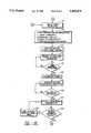
- FIG. 3is a block and schematic diagram of microprocessor control circuitry usable in the system of FIG. 1;
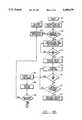
- FIG. 4A, 4B and 4Care flow diagrams of software programs for use by the microprocessor of FIG. 3;
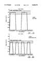
- FIGS. 5A-5Fare examples of heating curves for closing wounds on various types of tissue.
- FIG. 6is a top view of tissue being welded illustrating placement of a laser spot in accordance with the invention.
- Biological tissuecomprises cell layers in a protein framework for tensile strength. All proteins are amino acids which have side chains which are dissolvable either in water or fat.
- Naturationis a process wherein the amino acids fold over, always in the same configuration for each protein type, when the protein leaves the interior of a cell and is confronted with tissue water. In such case, the hydrophobic portion of a side chain folds to the interior of the molecule.
- the proteinaceous components of the tissuecan be unfolded or denatured by the application of heat.
- Optical energycan be applied to the body's own tissues to substantially reproduce the prior tissue structure at a wound or severed tissue site without shrinking the tissue.
- energy from an optical energy sourcesuch as a laser, can be applied in a periodic cycle to bring the temperature of biological tissue somewhere above room temperature, but below the point at which tissue coagulates; preferably above 45 degrees centigrade and particularly to below about 65 degrees centigrade.
- Collagena major source of protein in the body, is denatured by application of such energy in such a way as to go into solution and form a "biological glue" to seal a lesion, anastomize a severed vessel, or reconstruct damaged tissue.
- biological glueWhen the source of heat is removed the proteins begin to re-nature and form an approximate replication of the prior tissue structure. As the body heals, the so-called “biological glue” will be reabsorbed and replaced by natural tissue.
- Optical energy of a particular wavelengthis converted to heat in tissue which absorbs energy at that wavelength.
- optical energy having a wavelength of about 1.2 to 1.4 micrometersis relatively unattenuated in both water and blood and, so, is particularly advantageous for use as an optical energy source for the formation of a "biological glue" in order to effect repair of gastrointestinal tract tissue, close skin wounds (whether originating accidentally, intentionally or through biological processes), and repair and reconstruct tissue such as reproductive tissue, tendons, and vascular tissue, provided the intensity, exposure time and spot size of the beam at its point of incidence on the tissue are controlled to keep the energy absorption by the tissue within the desirable range.
- a suitable wavelengthis obtainable using a commercially available Nd:YAG laser configured to generate optical energy at a wavelength of about 1.32 micrometers.
- FIG. 1illustrates a surgical system for achieving tissue welding in accordance with the invention.
- the systemhas a source of optical energy, laser 20, which is preferably of the Nd:YAG crystalline variety wherein an yttrium-aluminum-garnet(YAG) rod is doped with neodymium (Nd) ions as the active light-producing element.
- a laser 20includes a resonant cavity for amplifying the emitted light and pumping means, such as a DC Krypton arc lamp or diode, for supplying energy to create a population inversion of the normal energy state of Nd ions.
- the population inversionresults in the stimulated emission of light according to well-known laser principles.
- Nd:YAG laserswill emit light at a fundamental dominant wavelength of 1.06 micrometers. Such lasers also emit light at a secondary wavelength of approximately 1.322 micrometers. Proper utilization of this secondary mode in laser operation requires the dominant emission, which has a greater amplitude than the secondary emission, to be suppressed. Typically, peak power output at this secondary emission level is 20-30% of the continuous wave peak power output dominant level. It is the secondary wavelength that is utilized in the method and apparatus of the invention.
- laser 20includes a power supply circuit for activating the pumping arc lamp and cooling means for cooling the laser.
- a suitable Nd:YAG laser for use in this inventionis produced by PROCLOSURE INC., Orlando, Fla. 32809.
- a lens 21is provided to focus the emerging coherent light beam from laser 20 into an optical fiber 22.
- Lens 21may comprise a system of lenses.
- Optical fiber 22efficiently transmits the desired wavelength.
- Optical fiber 22provides a flexible conduit for guiding the optical energy from the laser into a hand-piece or wand 23 which is manipulable by the physician.
- a shutter 24is located, preferably, between laser 20 and lens 21.
- Hand-piece 23contains a shutter switch 25 which is preferably a foot switch that controls release of the laser energy and which may be actuated by either the hand or the foot of the operator.
- a timer 26is provided to control the shutter cycle and duration, and, thereby, the energy exposure of the tissue to the laser.
- Hand-piece 23may include a lens (not shown) for focusing or defocusing the beam.
- hand-piece 23includes means to enable the physician to set the working distance between the tissue to be irradiated and the distalmost end of the optical fiber or lens.
- a sliding scale 27or fixed scale which cooperates with a protective case 28 on the end of optical fiber 22 controls the working distance, and hence the diameter of the beam spot.
- the divergence of the beamis used to control the beam diameter as the distance between the distalmost end of the fiber 22 and the tissue is increased or decreased.
- the following electro-optical parametersrequire proper adjustment for each type of tissue: output power, time exposure, duration between exposure, and beam spot size.
- the thermal effects on the tissuecan be controlled by proper selection of the electro-optical parameters.
- Power densitymeasures the energy concentration of the applied light beam and is typically expressed in watts per square centimeter area of the applied beam spot. Power density is directly related to the amount of heat that will be produced at a given absorptivity. Radiant exposure, expressed in joules per square centimeter, is a measure of the power density multiplied by the exposure time. If the wavelength of the applied beam is poorly absorbed, more heat can be generated by increasing the time of tissue exposure to the applied beam.
- Laser output power and beam spot size selectionsaffect the power density; overall radiant exposure is affected by power density, time exposure and duration between exposures selections.
- Suitable means for control of the power output of laser 20is provided by a control unit 40, described further with reference to FIG. 3, below.
- Optical output power detector 41is provided for initial calibration of the beam of laser 20 at start-up and a second detector 42, which always receives a portion of the beam of laser 20 output.
- the power delivered to the tissue surfaceshould be maintained under 2 watts for a 1-3 mm distance between the tip of a 0.400 ⁇ diameter fiber and the tissue for purposes of tissue reconstruction by laser 20 as described herein.
- the objectis to deliver a specific amount of energy per volume of tissue. For a given spot size, which is related to the volume of tissue exposed, there are many combinations of power output and time exposure which will deliver equivalent amounts of energy. To-wit, power delivered to the tissue typically ranges between 0.5 and 2 watts; although power delivered could go higher if the time exposure were reduced commensurately.
- TEM 00specifically, a more concentrated beam results which can be used for cutting purposes at higher power output or for achieving very small beam spot size for tissue reconstruction.
- multimode transmissioncan be used for tissue reconstruction, but the beam spot size can not be as finely focused as the TEM 00 mode. However, if the beam is defocused, less power is delivered per unit area.
- data relating to appropriate settings of electro-optical parameters for various tissue typescan be coded on a computer memory device, such as floppy disc or programmable read-only memory computer chip.
- the functions of control unit 40 and timer 26can be computer controlled to adjust automatically the power level, and time exposure, duration between exposures, and display the proper spot size upon input of tissue type and the operating conditions by the physician or surgeon.
- the system of FIG. 1also includes a marker laser 30, illustratively a low-power helium-neon laser, which is coaligned with the infrared beam of laser 20.
- Laser 30can be of any type which emits radiation in the visible range of the electromagnetic spectrum.
- the power rating of the helium-neon marker laser 30is preferably between 0.5-5 mWatts. Marker laser 30 can be arranged so that its focal point coincides with that of the main operating laser 20.
- FIG. 3shows suitable circuitry for implementation of the functions of the control unit 40 and timer 26 which utilizes a microprocessor or computer 50, such as provided in a conventional personal computer, for controlling parameters of the optical beam so as to deliver the appropriate amount of energy to the tissue reconstruction site.
- a microprocessor or computer 50such as provided in a conventional personal computer, for controlling parameters of the optical beam so as to deliver the appropriate amount of energy to the tissue reconstruction site.
- the computer 50accesses a data base stored in a memory device to establish appropriate settings for power level, time exposure, duration between exposures, and spot size.
- Optical output poweris controlled by delivery of a signal from the microprocessor to the conventional current control circuitry for the power supply of the laser 20.
- a digital-to-analog converter 62is connected to receive a digital current control signal from the microprocessor 50.
- the analog output of the converter 62is amplified by an amplifier 64 and then converted to a frequency signal by a voltage-to-frequency converter 65.
- the output of the converter 65is used via an isolating circuit 66 to drive a frequency-to-voltage converter 67 to deliver a signal from a power source 68 and voltage regulators 69, 70 through an amplifier 71 to the power control input of the laser 20.
- the isolation between the computer 50 and the laser 20is provided for protective purposes and may be achieved through use of an optocoupler.
- Verification of power setting accuracyis accomplished initially by requiring that the wand 23 end of the optical fiber 22 be inserted in the calibration port of power detector 41 located in a system console (not shown).
- the power detector 41may take the form of a coherent power detector, such as a thermal calorimeter.
- the output of the detector 41is amplified by an amplifier 72 and converted in an analog-to-digital converter 73 for input to the computer 50.
- the computer 50then performs a calibration subroutine to adjust the digital output to the converter 62 and thus to the laser power source, until the desired optical power output is read at the power detector 41. If the intensity of the beam output is too low, the value of the digital signal to converter 62 is incremented; if the output is too high, it is decremented. The computer 50 will then clear the system for operation outside of the receptacle under control of the shutter switches 25 and timer 26.
- Subsequent beam output adjustmentis undertaken by computer 50, in accordance with well-known principles, by which a small amount of the optical output is diverted by the beam splitter 43 (FIG. 1) for measurement by the detector 42, which suitably takes the form of a photodiode connected through an amplifier 74 and an analog-to-digital converter 75 to deliver a power level input to the computer 50.
- the photodiode 42 circuitprovides a continuous feedback loop through the computer 50 for power output verification.
- a shutter switch 25(FIG. 1) is provided control to emissions of the beam toward the tissue.
- the computer 50also serves the function of a timer 26 (FIG. 1) to limit the total time for which shutter 24 permits the beam from laser 20 to reach the tissue on any one shot.
- Computer 50also sets the duration between exposures.
- the shutter 24is arranged to normally be in a beam blocking position.
- the switch 25is connected to the computer 50 with the aid of an amplifier 76, as shown in FIG. 3, and programming is provided so that a counter is set up to increment for each clock pulse received during the time that shutter 24 is open.
- the shutterWhen the count indicates that the total specified exposure time set by computer 50 is reached, the shutter will be closed and blocked from reopening until a predetermined time delay has passed.
- the exact exposure time and time delaysare explained in more detail in FIGS. 5A-5C.
- delay and exposure timeit is ensured that each passage of beam energy from the laser 20 will have the required energy to denature tissue without coagulation. Cycling the tissue exposure in this manner permits the user to overlap welds without overheating the tissue.
- the timer 26 and shutter control circuitryare possible and that, in particular, the function by programming in computer 50 can be replaced by hardwired timer circuitry, if desired.
- the diameter or the beam spot at the point of impact with the tissueis controlled by setting the working distance from the distalmost end of the fiber 22 to the tissue. As shown in FIG. 2, this is accomplished by manual manipulation of the sliding scale 27 (or fixed scale) or probe to achieve the distance specified by the computer 50 to give the required beam diameter and beam energy density required for the subject tissue type and thickness. In response to input of the tissue characteristics, the computer displays the required setting. It will be appreciated that beam shaping may be accomplished in other ways and that the scale movement can be accomplished automatically, if desired. The shown means is, however, a simple workable approach that lends itself readily and inexpensively for use on a disposable optical fiber 22 for use in a sterile environment.
- tissue characteristicsFor input of tissue characteristics to the computer 50 a conventional data input device, such as a keyboard is used. Known touch screen or voice activated input devices may also be used. It is preferable for the input process to be undertaken under prompting by tissue type and thickness selection menus appearing on a visual display.
- FIGS. 4A-4Cpresent an overall flow diagram of the software steps performed by the computer 50 for controlling the parameters of the beam in accordance with selected tissue characteristics.
- the computer 50undergoes a series of checks.
- instructionsare given at 102 on a display device, such as a cathode ray tube screen, for insertion of nonwand end of the fiber into the laser console.
- the fiberIn order to engage the laser power supply, the fiber has to be in the inserted "power output" ready position. If the fiber is not in the correct position the power supply to the system will be disabled at 103, 104, preventing operation of the laser 20 until a correction is made at 105.
- steps 102, 103 and 106can be eliminated if the fiber 22 is built into the laser system.
- the illustrated embodimentcontemplates the use of a key switch on the operating console, so the laser system awaits the positioning of that switch to the on position before proceeding.
- the programUpon receipt at 107 of the awaited keyswitch signal, the program then proceeds, at 110, the program initiates a signal to fire the krypton lamp to activate the laser 20.
- a determinationis made, such as by looking at the signal from detector 42 (FIG. 3) at 111 to ensure that the lamp is on. If the lamp is not on, retriggering is initiated at 112. If after a predetermined number (x) attempts, the lamp does not light, a message is displayed at 114 to replace the lamp or repair the power supply.
- This predetermined number xis adjustable and can be set by the user.
- the programthen proceeds to do some preliminary checks, such as checking the status of the laser cooling system at 108. For example, the deionized water is checked for proper conductivity, pressure and temperature. Other checks and diagnostics can also be run. Also, security subroutines can be implemented at this or another stage to ensure that only authorized individuals operate the beam itself. Should the diagnostics or other checks indicate some discrepancy at 109, the program will be directed to block further operation of the system, as at 104. If everything checks out the program then moves to an input requesting posture to define the beam according to the tissue to which it will be applied. At 115, tissue characteristics are entered into the computer 50.
- a suitable way to accomplish thatis to utilize a menu-driven tissue selection process. Available tissue selections are displayed on the screen, and input is solicited. Once tissue type is entered, the menu will be changed to solicit input as to tissue thickness. When the tissue thickness has been selected, the computer 50 addresses data stored in a memory device, such as a disk in a disk drive, and at 116 determines the laser operation parameters appropriate for the selected tissue characteristics.
- a memory devicesuch as a disk in a disk drive
- tissue type and thicknessit is advisable to provide some feedback to the user on tissue type and thickness to guard against input error. This can be done using any of several well known techniques.
- One wayis to display graphic representations of the selected tissue type and thickness on a display screen to provide an easily identifiable visual check to give reassurance to the user.
- the laser parameters obtained from lookup in the memory storage deviceinclude a combination of laser power (Pr), exposure time (Tr), duration between exposures (Dr) and fiber tip position (Fr) settings that will deliver a controlled amount of optical energy to the selected tissue type and thickness to nondestructively convert it to a denatured proteinaceous collagenous substance to close or join it together without injuriously shrinking the tissue.
- Prlaser power
- Trexposure time
- Drduration between exposures
- Frfiber tip position
- the laser power and exposure time parametersare fed to assembly programs for direct control of the power and shutter control circuitry described previously.
- instructions for manual setting of the fiber guide sliding scale 27 to establish the correct fiber tip position (Fr)are displayed on the screen at 117.
- a handpiece with fiber guidesuch as a flexible stainless steel wire having a fixed length (Fr) is used.
- a handpiece with a guide having a different lengthis selected.
- Shutter switch 25 actuationis monitored at 122.
- the actual laser beam output reading (Pa) detected by the detector 41(FIG. 3) is compared with the computer 50 designated reference output Pr.
- the lamp current control hardwareis adjusted until the measured output power is the same as the computer specified output power.
- the switch 25is then closed at 126.
- the usercan proceed to control the shutter 24 with the switch 25 at 128 in order to conduct the tissue joining process.
- the usercan elect at 129 to revise the parameters to those more suited to another tissue, whereupon the program will repeat the previous steps.
- Depressing the switch 25will open the shutter 24 for tissue welding at 130.
- the shutter open timewill be monitored as already described, with the shutter 24 closing when the timed actual exposure time Ta reaches the specified exposure time Tr, at 131.
- the footswitch status(depressed or released) is determined at 134.
- the timeris reset and the program directed back to step 127 to ready the system for another shot.
- the programcan be modified and embellished to meet specific needs. It can be integrated with a program to display patient case history data and to update the patient file automatically to record the details of the procedure applied to that patient.
- the apparatus of FIG. 1is used for skin closure at a lesion site.
- the tissue edges of the lesionare brought into close approximation by manual manipulation, for example.
- Hand-piece 23is positioned above the lesion at such a distance as to produce the desired beam spot size.
- a 400 ⁇ diameter fiberis used, which has been found to have a total dispersion angle of about 12.0° ⁇ 2°.
- the diameter at the spotis determined to be 400 ⁇ +2 d tan (6.0° ⁇ 1°), where d is the distance between the fiber tip and the tissue.
- the power, time exposure and spot sizeare set so as to heat the tissue above 45 degrees centigrade, but below the temperature at which tissue coagulates (typically 64°-65° C.).
- Typical spot sizesrange from 0.57 mm to 1.2 mm for levels of power delivered to the tissue ranging from 0.5 to 2 watts, and time durations (Dr and Tr) range from about 0.5 to 1.0 seconds.
- the tissue at the lesion siteis heated to a temperature sufficient to cause denaturization of the tissue proteins to the depth necessary to reconstruct the tissue in the lesion irrespective of whether the operating field is bloody or wet.
- the electro-optical parametersare set and controlled in response to input as to tissue type and thickness. Parameters may be specified for the reconstruction of many soft tissues such as; vascular, skin,, tendon, vas deferens, fallopian tubes, gastrointestinal tract, dura, and sclera. With an appropriately controlled moldification of the level of power delivered to the tissue under repair, cartilage and tympanic membranes can also be repaired in accordance with the invention described hereinabove.
- FIG. 5A-5Fthere is shown exemplary heating curves for various tissue types.
- the tissue and laser parameters for these curvesare summarized in the following Table I. These parameters are by no means all exclusive; it is envisioned that other parameters can be used with modifications and it is intended that this table be exemplary of a preferred embodiment only.
- tissueis denatured without coagulating.
- tissueis denatured without coagulating.
- FIG. 6there is shown spot placement using an exemplary technique of closing closely approximated edges of tissue.
- this exemplary techniqueclosely approximated edges along an incision line are placed adjacent each other.
- Probe 27is positioned adjacent the tissue to be welded and the foot pedal is depressed to weld a first spot. While the foot pedal is depressed, the probe 27 is then positioned adjacent to the next spot along the incision line, to a second spot that overlaps the first spot. The user continues to weld in this manner until the incision is completely sealed.
- the tissuecan be continuously welded along the incision line by overlapping exposures and spot.
- the tissueremains at a denaturing temperature while preventing coagulation and shrinkage. Due to preselected (on/off) exposure cycle times repeatedly exposing the same spot to optical energy from hand piece 23 will not injure the tissue or negate the efficacy of closure.
- the laser energycan be transmitted to the patient treatment site by an articulated arm with mirrors or it can be transmitted to the interior of a patient by endoscope.
- materials other than neodymium-doped crystalline yttrium-aluminum-garnetcan be used as a lasing medium to generate optical energy at the desired wavelengths.
Landscapes
- Health & Medical Sciences (AREA)
- Surgery (AREA)
- Life Sciences & Earth Sciences (AREA)
- Physics & Mathematics (AREA)
- Engineering & Computer Science (AREA)
- General Health & Medical Sciences (AREA)
- Nuclear Medicine, Radiotherapy & Molecular Imaging (AREA)
- Veterinary Medicine (AREA)
- Public Health (AREA)
- Biomedical Technology (AREA)
- Heart & Thoracic Surgery (AREA)
- Medical Informatics (AREA)
- Molecular Biology (AREA)
- Animal Behavior & Ethology (AREA)
- Otolaryngology (AREA)
- Optics & Photonics (AREA)
- Electromagnetism (AREA)
- Laser Surgery Devices (AREA)
Abstract
Description
TABLE I __________________________________________________________________________LASER PARAMETERS FOR VARIOUS TISSUE TYPES Approximate Tissue Spot Size Exposure Tissue Final Thickness Probe Diameter Range Of Duration Energy Trans- Tissue In Millimeters Distance (with 400μ fiber) Power (in Watts) On (Tr)/Off (Dr) ferred J/CM.sup.2 __________________________________________________________________________Artery 1 1 mm .575-.646 mm .5-.7 0.5 sec/0.5 sec 4.63 Artery 2 1 mm .575-.646 mm .65-.85 0.5 sec/0.5 sec 5.79 Artery/Vein 3 1 mm .575-.646 mm 1.1-1.3 0.5 sec/0.5 sec 9.26 Fallopian Tube 3 1 mm .575-.646 mm .65-.85 0.5 sec/0.5 sec 5.79 Fallopian Tube 4 1 mm .575-.646 mm .65-.85 0.5 sec/0.5 sec 5.79 Fallopian Tube 5 1 mm .575-.646 mm .65-.85 0.5 sec/0.5 sec 5.79 Skin 3 3 mm .925-1.14 mm 1.65-1.85 1.0 sec/1.0 sec 13.31 Vas Deferens 3 1 mm .574-646 mm .65-.85 0.5 sec/0.5 sec 5.79 Tendon 3 3 mm .925-1.14 mm .65-.85 1.0 sec/1.0 sec 5.7 Tendon 4 3 mm .925-1.14 mm .65-.85 1.0 sec/1.0 sec 5.7 Tendon 5 3 mm .925-1.14 mm .65-.85 1.0 sec/1.0 sec 5.7 __________________________________________________________________________
Claims (16)
Priority Applications (1)
| Application Number | Priority Date | Filing Date | Title |
|---|---|---|---|
| US07/934,167US5409479A (en) | 1983-10-06 | 1992-08-24 | Method for closing tissue wounds using radiative energy beams |
Applications Claiming Priority (5)
| Application Number | Priority Date | Filing Date | Title |
|---|---|---|---|
| US06/539,527US4672969A (en) | 1983-10-06 | 1983-10-06 | Laser healing method |
| US07/062,861US4854320A (en) | 1983-10-06 | 1987-06-16 | Laser healing method and apparatus |
| US07/380,622US5002051A (en) | 1983-10-06 | 1989-07-14 | Method for closing tissue wounds using radiative energy beams |
| US07/639,025US5140984A (en) | 1983-10-06 | 1991-01-09 | Laser healing method and apparatus |
| US07/934,167US5409479A (en) | 1983-10-06 | 1992-08-24 | Method for closing tissue wounds using radiative energy beams |
Related Parent Applications (1)
| Application Number | Title | Priority Date | Filing Date |
|---|---|---|---|
| US07/639,025Continuation-In-PartUS5140984A (en) | 1983-10-06 | 1991-01-09 | Laser healing method and apparatus |
Publications (1)
| Publication Number | Publication Date |
|---|---|
| US5409479Atrue US5409479A (en) | 1995-04-25 |
Family
ID=27490323
Family Applications (1)
| Application Number | Title | Priority Date | Filing Date |
|---|---|---|---|
| US07/934,167Expired - Fee RelatedUS5409479A (en) | 1983-10-06 | 1992-08-24 | Method for closing tissue wounds using radiative energy beams |
Country Status (1)
| Country | Link |
|---|---|
| US (1) | US5409479A (en) |
Cited By (77)
| Publication number | Priority date | Publication date | Assignee | Title |
|---|---|---|---|---|
| US5618284A (en)* | 1985-09-27 | 1997-04-08 | Sunrise Technologies | Collagen treatment apparatus |
| US5713891A (en)* | 1995-06-02 | 1998-02-03 | Children's Medical Center Corporation | Modified solder for delivery of bioactive substances and methods of use thereof |
| US5746735A (en)* | 1994-10-26 | 1998-05-05 | Cynosure, Inc. | Ultra long pulsed dye laser device for treatment of ectatic vessels and method therefor |
| US5810801A (en)* | 1997-02-05 | 1998-09-22 | Candela Corporation | Method and apparatus for treating wrinkles in skin using radiation |
| US5817153A (en)* | 1995-10-11 | 1998-10-06 | Sulzer Innotec Ag | Method of photo-oxidative treatment of tissues containing collagen |
| EP0763371A3 (en)* | 1995-09-15 | 1999-04-14 | ESC Medical Systems Ltd. | Method and apparatus for skin rejuvenation and wrinkle smoothing |
| US5970983A (en)* | 1996-05-15 | 1999-10-26 | Esc Medical Systems Ltd. | Method of laser surgery |
| US6071303A (en)* | 1996-12-08 | 2000-06-06 | Hearten Medical, Inc. | Device for the treatment of infarcted tissue and method of treating infarcted tissue |
| US6211335B1 (en) | 1995-01-20 | 2001-04-03 | The Microsearch Foundation Of Australia | Method of tissue repair |
| US6221068B1 (en)* | 1998-01-15 | 2001-04-24 | Northwestern University | Method for welding tissue |
| US6327506B1 (en)* | 1999-04-14 | 2001-12-04 | Teruaki Yogo | Far infrared heating apparatus |
| US6402739B1 (en)* | 1998-12-08 | 2002-06-11 | Y-Beam Technologies, Inc. | Energy application with cooling |
| US6447503B1 (en)* | 1998-01-29 | 2002-09-10 | International Business Machines Corporation | Laser dermablator and dermablation |
| US6451007B1 (en)* | 1999-07-29 | 2002-09-17 | Dale E. Koop | Thermal quenching of tissue |
| US6494900B1 (en)* | 1997-01-06 | 2002-12-17 | Norman Salansky | Method for localized low energy photon therapy (LEPT) |
| US20020198517A1 (en)* | 2001-04-10 | 2002-12-26 | Alfano Robert R. | Gelatin based and Power-gelTM as solders for Cr4+ laser tissue welding and sealing of lung air leak and fistulas in organs |
| US6530919B1 (en)* | 1998-10-30 | 2003-03-11 | Redfield, Inc. | Infrared coagulator with disposable tip light guide |
| US20030191511A1 (en)* | 1999-04-16 | 2003-10-09 | Tony R. Brown | Device for shaping infarcted heart tissue and method of using the device |
| US6685730B2 (en) | 2001-09-26 | 2004-02-03 | Rice University | Optically-absorbing nanoparticles for enhanced tissue repair |
| US20040034340A1 (en)* | 1999-10-13 | 2004-02-19 | Spineco, Inc., An Ohio Corporation | Smart dissector |
| US6699245B2 (en) | 2001-02-05 | 2004-03-02 | A-Med Systems, Inc. | Anastomosis system and related methods |
| US20040082941A1 (en)* | 1999-03-15 | 2004-04-29 | Connors Kevin P. | Tissue treatment device and method |
| US20040176752A1 (en)* | 2003-03-06 | 2004-09-09 | Alfano Robert R. | System and methods for laser treatment of ocular tissue |
| US20040230185A1 (en)* | 2003-03-27 | 2004-11-18 | Cierra, Inc. | Energy based devices and methods for treatment of patent foramen ovale |
| US20040230260A1 (en)* | 2003-07-18 | 2004-11-18 | Macfarland Dean A. | System and method for low average power dermatologic light treatment device |
| US20040243122A1 (en)* | 2003-02-13 | 2004-12-02 | Coaptus Medical Corporation | Transseptal closure of a patent foramen ovale and other cardiac defects |
| US20040267191A1 (en)* | 2003-03-27 | 2004-12-30 | Cierra, Inc. | Methods and apparatus for treatment of patent foramen ovale |
| US20050021016A1 (en)* | 2003-03-27 | 2005-01-27 | Cierra, Inc. | Energy based devices and methods for treatment of anatomic tissue defects |
| US20050034735A1 (en)* | 2003-03-27 | 2005-02-17 | Cierra, Inc. | Methods and apparatus for treatment of patent foramen ovale |
| US20050049658A1 (en)* | 2003-08-25 | 2005-03-03 | Connors Kevin P. | System and method for heating skin using light to provide tissue treatment |
| US20050080406A1 (en)* | 2003-03-27 | 2005-04-14 | Cierra, Inc. | Energy based devices and methods for treatment of patent foramen ovale |
| US20050137655A1 (en)* | 2003-12-22 | 2005-06-23 | Macfarland Dean A. | System and method for flexible architecture for dermatologic treatments utilizing multiple light sources |
| US20050197681A1 (en)* | 2004-02-06 | 2005-09-08 | Lumiphase Inc. | Method and device for the treatment of mammalian tissues |
| US20050228283A1 (en)* | 2003-06-10 | 2005-10-13 | Gifford Hanson S | Methods and apparatus for non-invasively treating atrial fibrillation using high intensity focused ultrasound |
| US20060025838A1 (en)* | 1999-04-16 | 2006-02-02 | Laufer Michael D | Device for shaping infarcted heart tissue and method of using the device |
| US20060052847A1 (en)* | 2003-08-25 | 2006-03-09 | Davenport Scott A | Method and system for treatment of post-partum abdominal skin redundancy or laxity |
| US20060057903A1 (en)* | 2002-12-11 | 2006-03-16 | Yazaki Corporation | Method of connecting and structure of connecting electric wire and connection terminal |
| US20060069310A1 (en)* | 2004-09-30 | 2006-03-30 | Couvillon Lucien A Jr | Programmable brake control system for use in a medical device |
| US20060074410A1 (en)* | 2004-06-21 | 2006-04-06 | Cierra, Inc. | Energy based devices and methods for treatment of anatomic tissue defects |
| US20060079870A1 (en)* | 2004-10-07 | 2006-04-13 | Barry Robert L | Systems and methods for shrinking and/or securing cardiovascular tissue |
| US20060122680A1 (en)* | 2003-02-13 | 2006-06-08 | Auth David C | Systems and methods for securing cardiovascular tissue |
| US20060212098A1 (en)* | 2005-01-13 | 2006-09-21 | Constantinos Demetriou | Method and apparatus for treating a diseased nail |
| US20060271089A1 (en)* | 2005-04-11 | 2006-11-30 | Cierra, Inc. | Methods and apparatus to achieve a closure of a layered tissue defect |
| US7153298B1 (en)* | 2003-03-28 | 2006-12-26 | Vandolay, Inc. | Vascular occlusion systems and methods |
| US20070073367A1 (en)* | 2005-09-28 | 2007-03-29 | Jones Christopher J | Method of treating cellulite |
| US20070083190A1 (en)* | 2005-10-11 | 2007-04-12 | Yacov Domankevitz | Compression device for a laser handpiece |
| US20070093804A1 (en)* | 2005-10-17 | 2007-04-26 | Coaptus Medical Corporation | Control systems for patient devices, including devices for securing cardiovascular tissue, and associated methods |
| US20070123852A1 (en)* | 2003-03-27 | 2007-05-31 | Cierra, Inc. | Methods and apparatus for closing a layered tissue defect |
| US20070156210A1 (en)* | 2005-01-14 | 2007-07-05 | Co-Repair, Inc., A California Corporation | Method for the treatment of heart tissue |
| US20070162093A1 (en)* | 2006-01-11 | 2007-07-12 | Porter Roger D | Therapeutic laser treatment |
| US20070173799A1 (en)* | 2005-09-01 | 2007-07-26 | Hsia James C | Treatment of fatty tissue adjacent an eye |
| US20070176262A1 (en)* | 2005-08-11 | 2007-08-02 | Ernest Sirkin | Series connection of a diode laser bar |
| US20070198003A1 (en)* | 2005-12-23 | 2007-08-23 | Yacov Domankevitz | Treating dermatological conditions using an alexandrite laser |
| US20080009923A1 (en)* | 2006-06-14 | 2008-01-10 | Paithankar Dilip Y | Treatment of Skin by Spatial Modulation of Thermal Heating |
| US20080140069A1 (en)* | 2006-12-07 | 2008-06-12 | Cierra, Inc. | Multi-electrode apparatus for tissue welding and ablation |
| US20080221649A1 (en)* | 2007-03-09 | 2008-09-11 | Agustina Echague | Method of sequentially treating tissue |
| US20090287204A1 (en)* | 2005-01-14 | 2009-11-19 | Co-Repair, Inc. | System And Method For The Treatment Of Heart Tissue |
| WO2008139444A3 (en)* | 2007-05-10 | 2010-02-18 | Seraffix Ltd. | System and method for bonding living tissue |
| US7722600B2 (en) | 2003-08-25 | 2010-05-25 | Cutera, Inc. | System and method for heating skin using light to provide tissue treatment |
| US20100280545A1 (en)* | 2007-05-10 | 2010-11-04 | Seraffix Ltd. | System and method for bonding living tissue |
| US20110098170A1 (en)* | 2008-04-08 | 2011-04-28 | Marc Le Monnier | Cell-like structure manufacturing method, cell-like structure, and corresponding equipment |
| US7972330B2 (en) | 2003-03-27 | 2011-07-05 | Terumo Kabushiki Kaisha | Methods and apparatus for closing a layered tissue defect |
| US20110172746A1 (en)* | 2010-01-12 | 2011-07-14 | Roger Porter | High Level Laser Therapy Apparatus and Methods |
| US20110190745A1 (en)* | 2009-12-04 | 2011-08-04 | Uebelhoer Nathan S | Treatment of sweat glands |
| US20110230817A1 (en)* | 2010-03-16 | 2011-09-22 | Moy Ronald L | Devices for light treatment of wounds to reduce scar formation |
| US8915948B2 (en) | 2002-06-19 | 2014-12-23 | Palomar Medical Technologies, Llc | Method and apparatus for photothermal treatment of tissue at depth |
| US9028536B2 (en) | 2006-08-02 | 2015-05-12 | Cynosure, Inc. | Picosecond laser apparatus and methods for its operation and use |
| US9780518B2 (en) | 2012-04-18 | 2017-10-03 | Cynosure, Inc. | Picosecond laser apparatus and methods for treating target tissues with same |
| WO2017212404A1 (en)* | 2016-06-09 | 2017-12-14 | Lumenis Ltd. | Apparatus and method for reducing laser beam attentuation in a liquid medium |
| US9907975B1 (en) | 2014-11-19 | 2018-03-06 | Roger D. Porter | Therapeutic laser treatment and transdermal stimulation of stem cell differentiation |
| US10245107B2 (en) | 2013-03-15 | 2019-04-02 | Cynosure, Inc. | Picosecond optical radiation systems and methods of use |
| US10434324B2 (en) | 2005-04-22 | 2019-10-08 | Cynosure, Llc | Methods and systems for laser treatment using non-uniform output beam |
| WO2021030616A1 (en)* | 2019-08-14 | 2021-02-18 | Open Water Internet Inc. | Multi-channel laser |
| CN112842520A (en)* | 2021-01-30 | 2021-05-28 | 南京理工大学 | Laser biological tissue welding seam self-adaptive path planning device and method thereof |
| EP3949886A1 (en)* | 2019-04-05 | 2022-02-09 | Intermedic Arfran, S.A. | Non-surgical system for the retraction of a patient's eyelid tissue, that can be coupled to any laser generator |
| US11418000B2 (en) | 2018-02-26 | 2022-08-16 | Cynosure, Llc | Q-switched cavity dumped sub-nanosecond laser |
| US11419679B2 (en) | 2018-03-29 | 2022-08-23 | Lumenis Ltd. | Optimization of BPH treatment using LEP (laser enucleation of prostate) |
Citations (4)
| Publication number | Priority date | Publication date | Assignee | Title |
|---|---|---|---|---|
| WO1985001445A1 (en)* | 1983-10-06 | 1985-04-11 | Sonomo Corporation | Laser healing method and apparatus |
| US4854320A (en)* | 1983-10-06 | 1989-08-08 | Laser Surgery Software, Inc. | Laser healing method and apparatus |
| US5002051A (en)* | 1983-10-06 | 1991-03-26 | Lasery Surgery Software, Inc. | Method for closing tissue wounds using radiative energy beams |
| US5140984A (en)* | 1983-10-06 | 1992-08-25 | Proclosure, Inc. | Laser healing method and apparatus |
- 1992
- 1992-08-24USUS07/934,167patent/US5409479A/ennot_activeExpired - Fee Related
Patent Citations (5)
| Publication number | Priority date | Publication date | Assignee | Title |
|---|---|---|---|---|
| WO1985001445A1 (en)* | 1983-10-06 | 1985-04-11 | Sonomo Corporation | Laser healing method and apparatus |
| US4672969A (en)* | 1983-10-06 | 1987-06-16 | Sonomo Corporation | Laser healing method |
| US4854320A (en)* | 1983-10-06 | 1989-08-08 | Laser Surgery Software, Inc. | Laser healing method and apparatus |
| US5002051A (en)* | 1983-10-06 | 1991-03-26 | Lasery Surgery Software, Inc. | Method for closing tissue wounds using radiative energy beams |
| US5140984A (en)* | 1983-10-06 | 1992-08-25 | Proclosure, Inc. | Laser healing method and apparatus |
Cited By (181)
| Publication number | Priority date | Publication date | Assignee | Title |
|---|---|---|---|---|
| US5618284A (en)* | 1985-09-27 | 1997-04-08 | Sunrise Technologies | Collagen treatment apparatus |
| US5746735A (en)* | 1994-10-26 | 1998-05-05 | Cynosure, Inc. | Ultra long pulsed dye laser device for treatment of ectatic vessels and method therefor |
| US6579284B2 (en)* | 1994-10-26 | 2003-06-17 | Cynosure, Inc. | Ultra long pulsed dye laser device for treatment of ectatic vessels and method therefor |
| US6391022B1 (en) | 1994-10-26 | 2002-05-21 | Cynosure, Inc. | Ultra long pulsed dye laser device for treatment of ectatic vessels and method therefor |
| US20050079997A1 (en)* | 1995-01-20 | 2005-04-14 | Owen Earl Ronald | Method of tissue repair |
| US6583117B2 (en) | 1995-01-20 | 2003-06-24 | The Microsearch Foundation Of Australia | Method of tissue repair |
| US6211335B1 (en) | 1995-01-20 | 2001-04-03 | The Microsearch Foundation Of Australia | Method of tissue repair |
| US5713891A (en)* | 1995-06-02 | 1998-02-03 | Children's Medical Center Corporation | Modified solder for delivery of bioactive substances and methods of use thereof |
| US6387089B1 (en) | 1995-09-15 | 2002-05-14 | Lumenis Ltd. | Method and apparatus for skin rejuvination and wrinkle smoothing |
| EP0763371A3 (en)* | 1995-09-15 | 1999-04-14 | ESC Medical Systems Ltd. | Method and apparatus for skin rejuvenation and wrinkle smoothing |
| US5817153A (en)* | 1995-10-11 | 1998-10-06 | Sulzer Innotec Ag | Method of photo-oxidative treatment of tissues containing collagen |
| US5970983A (en)* | 1996-05-15 | 1999-10-26 | Esc Medical Systems Ltd. | Method of laser surgery |
| US6071303A (en)* | 1996-12-08 | 2000-06-06 | Hearten Medical, Inc. | Device for the treatment of infarcted tissue and method of treating infarcted tissue |
| US6494900B1 (en)* | 1997-01-06 | 2002-12-17 | Norman Salansky | Method for localized low energy photon therapy (LEPT) |
| US6120497A (en)* | 1997-02-05 | 2000-09-19 | Massachusetts General Hospital | Method and apparatus for treating wrinkles in skin using radiation |
| US5810801A (en)* | 1997-02-05 | 1998-09-22 | Candela Corporation | Method and apparatus for treating wrinkles in skin using radiation |
| US6659999B1 (en) | 1997-02-05 | 2003-12-09 | Candela Corporation | Method and apparatus for treating wrinkles in skin using radiation |
| US6221068B1 (en)* | 1998-01-15 | 2001-04-24 | Northwestern University | Method for welding tissue |
| US6447503B1 (en)* | 1998-01-29 | 2002-09-10 | International Business Machines Corporation | Laser dermablator and dermablation |
| US6530919B1 (en)* | 1998-10-30 | 2003-03-11 | Redfield, Inc. | Infrared coagulator with disposable tip light guide |
| US6402739B1 (en)* | 1998-12-08 | 2002-06-11 | Y-Beam Technologies, Inc. | Energy application with cooling |
| US7618414B2 (en) | 1999-03-15 | 2009-11-17 | Cutera, Inc. | Tissue treatment system |
| US20060122585A1 (en)* | 1999-03-15 | 2006-06-08 | Acme Medical, Inc. | Tissue treatment system |
| US20070208326A1 (en)* | 1999-03-15 | 2007-09-06 | Connors Kevin P | Tissue treatment system |
| US7041094B2 (en) | 1999-03-15 | 2006-05-09 | Cutera, Inc. | Tissue treatment device and method |
| US7465307B2 (en) | 1999-03-15 | 2008-12-16 | Cutera, Inc. | Tissue treatment system |
| US20040082941A1 (en)* | 1999-03-15 | 2004-04-29 | Connors Kevin P. | Tissue treatment device and method |
| US6327506B1 (en)* | 1999-04-14 | 2001-12-04 | Teruaki Yogo | Far infrared heating apparatus |
| US20060025838A1 (en)* | 1999-04-16 | 2006-02-02 | Laufer Michael D | Device for shaping infarcted heart tissue and method of using the device |
| US20030191511A1 (en)* | 1999-04-16 | 2003-10-09 | Tony R. Brown | Device for shaping infarcted heart tissue and method of using the device |
| US7039469B2 (en) | 1999-04-16 | 2006-05-02 | Michael D. Laufer | Device for shaping infarcted heart tissue and method of using the device |
| US8285393B2 (en) | 1999-04-16 | 2012-10-09 | Laufer Michael D | Device for shaping infarcted heart tissue and method of using the device |
| US6451007B1 (en)* | 1999-07-29 | 2002-09-17 | Dale E. Koop | Thermal quenching of tissue |
| US7637906B2 (en) | 1999-07-29 | 2009-12-29 | Cooltouch, Incorporated | Thermal quenching of tissue |
| US20060282067A1 (en)* | 1999-07-29 | 2006-12-14 | Koop Dale E | Thermal quenching of tissue |
| US20040034340A1 (en)* | 1999-10-13 | 2004-02-19 | Spineco, Inc., An Ohio Corporation | Smart dissector |
| US6699245B2 (en) | 2001-02-05 | 2004-03-02 | A-Med Systems, Inc. | Anastomosis system and related methods |
| US20020198517A1 (en)* | 2001-04-10 | 2002-12-26 | Alfano Robert R. | Gelatin based and Power-gelTM as solders for Cr4+ laser tissue welding and sealing of lung air leak and fistulas in organs |
| US7033348B2 (en)* | 2001-04-10 | 2006-04-25 | The Research Foundation Of The City University Of New York | Gelatin based on Power-gel™ as solders for Cr4+laser tissue welding and sealing of lung air leak and fistulas in organs |
| US6685730B2 (en) | 2001-09-26 | 2004-02-03 | Rice University | Optically-absorbing nanoparticles for enhanced tissue repair |
| US10500413B2 (en) | 2002-06-19 | 2019-12-10 | Palomar Medical Technologies, Llc | Method and apparatus for treatment of cutaneous and subcutaneous conditions |
| US8915948B2 (en) | 2002-06-19 | 2014-12-23 | Palomar Medical Technologies, Llc | Method and apparatus for photothermal treatment of tissue at depth |
| US10556123B2 (en) | 2002-06-19 | 2020-02-11 | Palomar Medical Technologies, Llc | Method and apparatus for treatment of cutaneous and subcutaneous conditions |
| US7705265B2 (en)* | 2002-12-11 | 2010-04-27 | Yazaki Corporation | Method of connecting and structure of connecting electric wire and connection terminal |
| US20060057903A1 (en)* | 2002-12-11 | 2006-03-16 | Yazaki Corporation | Method of connecting and structure of connecting electric wire and connection terminal |
| US8052677B2 (en) | 2003-02-13 | 2011-11-08 | Coaptus Medical Corporation | Transseptal left atrial access and septal closure |
| US8021359B2 (en) | 2003-02-13 | 2011-09-20 | Coaptus Medical Corporation | Transseptal closure of a patent foramen ovale and other cardiac defects |
| US7257450B2 (en) | 2003-02-13 | 2007-08-14 | Coaptus Medical Corporation | Systems and methods for securing cardiovascular tissue |
| US20060122680A1 (en)* | 2003-02-13 | 2006-06-08 | Auth David C | Systems and methods for securing cardiovascular tissue |
| US20040243122A1 (en)* | 2003-02-13 | 2004-12-02 | Coaptus Medical Corporation | Transseptal closure of a patent foramen ovale and other cardiac defects |
| US20080312646A9 (en)* | 2003-02-13 | 2008-12-18 | Coaptus Medical Corporation | Transseptal closure of a patent foramen ovale and other cardiac defects |
| WO2004080321A1 (en)* | 2003-03-06 | 2004-09-23 | The Research Foundation Of Cuny | System and methods for laser treatment of ocular tissue |
| US20040176752A1 (en)* | 2003-03-06 | 2004-09-09 | Alfano Robert R. | System and methods for laser treatment of ocular tissue |
| US20060241581A1 (en)* | 2003-03-27 | 2006-10-26 | Cierra, Inc. | Energy based devices and methods for treatment of patent foramen ovale |
| US8038673B2 (en) | 2003-03-27 | 2011-10-18 | Terumo Kabushiki Kaisha | Energy based devices and methods for treatment of patent foramen ovale |
| US8075554B2 (en) | 2003-03-27 | 2011-12-13 | Terumo Kabushiki Kaisha | Energy based devices and methods for treatment of patent foramen ovale |
| US8066701B2 (en) | 2003-03-27 | 2011-11-29 | Terumo Kabushiki Kaisha | Energy based devices and methods for treatment of patent foramen ovale |
| US20060241582A1 (en)* | 2003-03-27 | 2006-10-26 | Cierra, Inc. | Energy based devices and methods for treatment of patent foramen ovale |
| US20060241584A1 (en)* | 2003-03-27 | 2006-10-26 | Cierra, Inc. | Energy based devices and methods for treatment of patent foramen ovale |
| US8465485B2 (en) | 2003-03-27 | 2013-06-18 | Terumo Kabushiki Kaisha | Energy based devices and methods for treatment of patent foramen ovale |
| US8057469B2 (en) | 2003-03-27 | 2011-11-15 | Terumo Kabushiki Kaisha | Methods and apparatus for treatment of patent foramen ovale |
| US8052678B2 (en) | 2003-03-27 | 2011-11-08 | Terumo Kabushiki Kaisha | Energy based devices and methods for treatment of patent foramen ovale |
| US20060276779A1 (en)* | 2003-03-27 | 2006-12-07 | Cierra, Inc. | Energy based devices and methods for treatment of patent foramen ovale |
| US8852181B2 (en) | 2003-03-27 | 2014-10-07 | Terumo Kabushiki Kaisha | Energy based devices and methods for treatment of anatomic tissue defects |
| US20040230185A1 (en)* | 2003-03-27 | 2004-11-18 | Cierra, Inc. | Energy based devices and methods for treatment of patent foramen ovale |
| US7165552B2 (en) | 2003-03-27 | 2007-01-23 | Cierra, Inc. | Methods and apparatus for treatment of patent foramen ovale |
| US20070044811A1 (en)* | 2003-03-27 | 2007-03-01 | Cierra, Inc. | Energy based devices and methods for treatment of patent foramen ovale |
| US7186251B2 (en) | 2003-03-27 | 2007-03-06 | Cierra, Inc. | Energy based devices and methods for treatment of patent foramen ovale |
| US6939348B2 (en) | 2003-03-27 | 2005-09-06 | Cierra, Inc. | Energy based devices and methods for treatment of patent foramen ovale |
| US20070078485A1 (en)* | 2003-03-27 | 2007-04-05 | Cierra, Inc. | Methods and apparatus for treatment of patent foramen ovale |
| US8070747B2 (en) | 2003-03-27 | 2011-12-06 | Terumo Kabushiki Kaisha | Energy based devices and methods for treatment of patent foramen ovale |
| US8038672B2 (en) | 2003-03-27 | 2011-10-18 | Terumo Kabushiki Kaisha | Energy based devices and methods for treatment of patent foramen ovale |
| US8038669B2 (en) | 2003-03-27 | 2011-10-18 | Terumo Kabushiki Kaisha | Energy based devices and methods for treatment of patent foramen ovale |
| US20070123852A1 (en)* | 2003-03-27 | 2007-05-31 | Cierra, Inc. | Methods and apparatus for closing a layered tissue defect |
| US8038671B2 (en) | 2003-03-27 | 2011-10-18 | Terumo Kabushiki Kaisha | Energy based devices and methods for treatment of patent foramen ovale |
| US20050131401A1 (en)* | 2003-03-27 | 2005-06-16 | Cierra, Inc. | Energy based devices and methods for treatment of anatomic tissue defects |
| US8021362B2 (en) | 2003-03-27 | 2011-09-20 | Terumo Kabushiki Kaisha | Methods and apparatus for closing a layered tissue defect |
| US7972330B2 (en) | 2003-03-27 | 2011-07-05 | Terumo Kabushiki Kaisha | Methods and apparatus for closing a layered tissue defect |
| US7922716B2 (en) | 2003-03-27 | 2011-04-12 | Terumo Kabushiki Kaisha | Energy based devices and methods for treatment of anatomic tissue defects |
| US20050131460A1 (en)* | 2003-03-27 | 2005-06-16 | Cierra, Inc. | Methods and apparatus for treatment of patent foramen ovale |
| US7914527B2 (en) | 2003-03-27 | 2011-03-29 | Terumo Kabushiki Kaisha | Energy based devices and methods for treatment of patent foramen ovale |
| US20050080406A1 (en)* | 2003-03-27 | 2005-04-14 | Cierra, Inc. | Energy based devices and methods for treatment of patent foramen ovale |
| US20050034735A1 (en)* | 2003-03-27 | 2005-02-17 | Cierra, Inc. | Methods and apparatus for treatment of patent foramen ovale |
| US7293562B2 (en) | 2003-03-27 | 2007-11-13 | Cierra, Inc. | Energy based devices and methods for treatment of anatomic tissue defects |
| US20050021016A1 (en)* | 2003-03-27 | 2005-01-27 | Cierra, Inc. | Energy based devices and methods for treatment of anatomic tissue defects |
| US20080004658A1 (en)* | 2003-03-27 | 2008-01-03 | Cierra, Inc. | Energy based devices and methods for treatment of anatomic tissue defects |
| US7637924B2 (en) | 2003-03-27 | 2009-12-29 | Terumo Kabushiki Kaisha | Methods and apparatus for treatment of patent foramen ovale |
| US20040267191A1 (en)* | 2003-03-27 | 2004-12-30 | Cierra, Inc. | Methods and apparatus for treatment of patent foramen ovale |
| US7153298B1 (en)* | 2003-03-28 | 2006-12-26 | Vandolay, Inc. | Vascular occlusion systems and methods |
| US20050228283A1 (en)* | 2003-06-10 | 2005-10-13 | Gifford Hanson S | Methods and apparatus for non-invasively treating atrial fibrillation using high intensity focused ultrasound |
| US7311701B2 (en) | 2003-06-10 | 2007-12-25 | Cierra, Inc. | Methods and apparatus for non-invasively treating atrial fibrillation using high intensity focused ultrasound |
| US20080058683A1 (en)* | 2003-06-10 | 2008-03-06 | Cierra, Inc. | Method and apparatus for non-invasively treating patent foramen ovale using high intensity focused ultrasound |
| US20040230260A1 (en)* | 2003-07-18 | 2004-11-18 | Macfarland Dean A. | System and method for low average power dermatologic light treatment device |
| US7291140B2 (en) | 2003-07-18 | 2007-11-06 | Cutera, Inc. | System and method for low average power dermatologic light treatment device |
| US20050049658A1 (en)* | 2003-08-25 | 2005-03-03 | Connors Kevin P. | System and method for heating skin using light to provide tissue treatment |
| US7722600B2 (en) | 2003-08-25 | 2010-05-25 | Cutera, Inc. | System and method for heating skin using light to provide tissue treatment |
| US20060052847A1 (en)* | 2003-08-25 | 2006-03-09 | Davenport Scott A | Method and system for treatment of post-partum abdominal skin redundancy or laxity |
| US8870856B2 (en) | 2003-08-25 | 2014-10-28 | Cutera, Inc. | Method for heating skin using light to provide tissue treatment |
| US8915906B2 (en) | 2003-08-25 | 2014-12-23 | Cutera, Inc. | Method for treatment of post-partum abdominal skin redundancy or laxity |
| US20080097419A1 (en)* | 2003-12-22 | 2008-04-24 | Macfarland Dean A | System and method for flexible architecture for dematologic treatments utilizing multiple light sources |
| US20050137655A1 (en)* | 2003-12-22 | 2005-06-23 | Macfarland Dean A. | System and method for flexible architecture for dermatologic treatments utilizing multiple light sources |
| US7326199B2 (en) | 2003-12-22 | 2008-02-05 | Cutera, Inc. | System and method for flexible architecture for dermatologic treatments utilizing multiple light sources |
| US7780652B2 (en) | 2003-12-22 | 2010-08-24 | Cutera, Inc. | System and method for flexible architecture for dermatologic treatments utilizing multiple light sources |
| US7887533B2 (en) | 2004-02-06 | 2011-02-15 | Clinique Dr Daniel Barolet Inc. | Device for the treatment of mammalian tissues |
| US20050197681A1 (en)* | 2004-02-06 | 2005-09-08 | Lumiphase Inc. | Method and device for the treatment of mammalian tissues |
| US7914523B2 (en) | 2004-02-06 | 2011-03-29 | Clinique Dr Daniel Barolet Inc. | Method for the treatment of mammalian tissues |
| US7367975B2 (en) | 2004-06-21 | 2008-05-06 | Cierra, Inc. | Energy based devices and methods for treatment of anatomic tissue defects |
| US8133221B2 (en) | 2004-06-21 | 2012-03-13 | Terumo Kabushiki Kaisha | Energy based devices and methods for treatment of anatomic tissue defects |
| US20060074410A1 (en)* | 2004-06-21 | 2006-04-06 | Cierra, Inc. | Energy based devices and methods for treatment of anatomic tissue defects |
| US20060069310A1 (en)* | 2004-09-30 | 2006-03-30 | Couvillon Lucien A Jr | Programmable brake control system for use in a medical device |
| US20060079870A1 (en)* | 2004-10-07 | 2006-04-13 | Barry Robert L | Systems and methods for shrinking and/or securing cardiovascular tissue |
| US7473252B2 (en) | 2004-10-07 | 2009-01-06 | Coaptus Medical Corporation | Systems and methods for shrinking and/or securing cardiovascular tissue |
| US8277495B2 (en) | 2005-01-13 | 2012-10-02 | Candela Corporation | Method and apparatus for treating a diseased nail |
| US20060212098A1 (en)* | 2005-01-13 | 2006-09-21 | Constantinos Demetriou | Method and apparatus for treating a diseased nail |
| US20070156210A1 (en)* | 2005-01-14 | 2007-07-05 | Co-Repair, Inc., A California Corporation | Method for the treatment of heart tissue |
| US20090287204A1 (en)* | 2005-01-14 | 2009-11-19 | Co-Repair, Inc. | System And Method For The Treatment Of Heart Tissue |
| US20060271040A1 (en)* | 2005-04-11 | 2006-11-30 | Cierra, Inc. | Methods and electrode apparatus to achieve a closure of a layered tissue defect |
| US8109274B2 (en) | 2005-04-11 | 2012-02-07 | Terumo Kabushiki Kaisha | Methods and electrode apparatus to achieve a closure of a layered tissue defect |
| US20060271089A1 (en)* | 2005-04-11 | 2006-11-30 | Cierra, Inc. | Methods and apparatus to achieve a closure of a layered tissue defect |
| US10434324B2 (en) | 2005-04-22 | 2019-10-08 | Cynosure, Llc | Methods and systems for laser treatment using non-uniform output beam |
| US20070176262A1 (en)* | 2005-08-11 | 2007-08-02 | Ernest Sirkin | Series connection of a diode laser bar |
| US20070173799A1 (en)* | 2005-09-01 | 2007-07-26 | Hsia James C | Treatment of fatty tissue adjacent an eye |
| US9028469B2 (en) | 2005-09-28 | 2015-05-12 | Candela Corporation | Method of treating cellulite |
| US20070073367A1 (en)* | 2005-09-28 | 2007-03-29 | Jones Christopher J | Method of treating cellulite |
| US20070083190A1 (en)* | 2005-10-11 | 2007-04-12 | Yacov Domankevitz | Compression device for a laser handpiece |
| US20070093804A1 (en)* | 2005-10-17 | 2007-04-26 | Coaptus Medical Corporation | Control systems for patient devices, including devices for securing cardiovascular tissue, and associated methods |
| US20070106214A1 (en)* | 2005-10-17 | 2007-05-10 | Coaptus Medical Corporation | Systems and methods for securing cardiovascular tissue, including via asymmetric inflatable members |
| US20070123824A1 (en)* | 2005-10-17 | 2007-05-31 | Coaptus Medical Corporation | Systems and methods for directing valves that control a vacuum applied to a patient |
| US20070198003A1 (en)* | 2005-12-23 | 2007-08-23 | Yacov Domankevitz | Treating dermatological conditions using an alexandrite laser |
| US7891362B2 (en) | 2005-12-23 | 2011-02-22 | Candela Corporation | Methods for treating pigmentary and vascular abnormalities in a dermal region |
| US8033284B2 (en) | 2006-01-11 | 2011-10-11 | Curaelase, Inc. | Therapeutic laser treatment |
| US20070162093A1 (en)* | 2006-01-11 | 2007-07-12 | Porter Roger D | Therapeutic laser treatment |
| US8316860B1 (en) | 2006-01-11 | 2012-11-27 | Curaelase, Inc. | Therapeutic laser treatment method |
| US8246611B2 (en) | 2006-06-14 | 2012-08-21 | Candela Corporation | Treatment of skin by spatial modulation of thermal heating |
| US9486285B2 (en) | 2006-06-14 | 2016-11-08 | Candela Corporation | Treatment of skin by spatial modulation of thermal heating |
| US20080009923A1 (en)* | 2006-06-14 | 2008-01-10 | Paithankar Dilip Y | Treatment of Skin by Spatial Modulation of Thermal Heating |
| US10966785B2 (en) | 2006-08-02 | 2021-04-06 | Cynosure, Llc | Picosecond laser apparatus and methods for its operation and use |
| US11712299B2 (en) | 2006-08-02 | 2023-08-01 | Cynosure, LLC. | Picosecond laser apparatus and methods for its operation and use |
| US9028536B2 (en) | 2006-08-02 | 2015-05-12 | Cynosure, Inc. | Picosecond laser apparatus and methods for its operation and use |
| US10849687B2 (en) | 2006-08-02 | 2020-12-01 | Cynosure, Llc | Picosecond laser apparatus and methods for its operation and use |
| US20080140069A1 (en)* | 2006-12-07 | 2008-06-12 | Cierra, Inc. | Multi-electrode apparatus for tissue welding and ablation |
| US20080221649A1 (en)* | 2007-03-09 | 2008-09-11 | Agustina Echague | Method of sequentially treating tissue |
| WO2008139444A3 (en)* | 2007-05-10 | 2010-02-18 | Seraffix Ltd. | System and method for bonding living tissue |
| US20100280545A1 (en)* | 2007-05-10 | 2010-11-04 | Seraffix Ltd. | System and method for bonding living tissue |
| EP2150182A4 (en)* | 2007-05-10 | 2012-01-18 | Seraffix Ltd | System and method for bonding living tissue |
| US20110098170A1 (en)* | 2008-04-08 | 2011-04-28 | Marc Le Monnier | Cell-like structure manufacturing method, cell-like structure, and corresponding equipment |
| US20110190745A1 (en)* | 2009-12-04 | 2011-08-04 | Uebelhoer Nathan S | Treatment of sweat glands |
| US20110172746A1 (en)* | 2010-01-12 | 2011-07-14 | Roger Porter | High Level Laser Therapy Apparatus and Methods |
| US8778002B2 (en) | 2010-03-16 | 2014-07-15 | Ronald L. Moy | Methods of light treatment of wounds to reduce scar formation |
| EP2547394A4 (en)* | 2010-03-16 | 2013-09-11 | Ronald L Moy | Light treatment of wounds to reduce scar formation |
| US20110230870A1 (en)* | 2010-03-16 | 2011-09-22 | Moy Ronald L | Methods of light treatment of wounds to reduce scar formation |
| US20110230817A1 (en)* | 2010-03-16 | 2011-09-22 | Moy Ronald L | Devices for light treatment of wounds to reduce scar formation |
| US11095087B2 (en) | 2012-04-18 | 2021-08-17 | Cynosure, Llc | Picosecond laser apparatus and methods for treating target tissues with same |
| US10305244B2 (en) | 2012-04-18 | 2019-05-28 | Cynosure, Llc | Picosecond laser apparatus and methods for treating target tissues with same |
| US12431683B2 (en) | 2012-04-18 | 2025-09-30 | Cynosure, Llc | Picosecond laser apparatus and methods for treating target tissues with same |
| US10581217B2 (en) | 2012-04-18 | 2020-03-03 | Cynosure, Llc | Picosecond laser apparatus and methods for treating target tissues with same |
| US12068571B2 (en) | 2012-04-18 | 2024-08-20 | Cynosure, Llc | Picosecond laser apparatus and methods for treating target tissues with same |
| US9780518B2 (en) | 2012-04-18 | 2017-10-03 | Cynosure, Inc. | Picosecond laser apparatus and methods for treating target tissues with same |
| US11664637B2 (en) | 2012-04-18 | 2023-05-30 | Cynosure, Llc | Picosecond laser apparatus and methods for treating target tissues with same |
| US11446086B2 (en) | 2013-03-15 | 2022-09-20 | Cynosure, Llc | Picosecond optical radiation systems and methods of use |
| US10245107B2 (en) | 2013-03-15 | 2019-04-02 | Cynosure, Inc. | Picosecond optical radiation systems and methods of use |
| US12193734B2 (en) | 2013-03-15 | 2025-01-14 | Cynosure, Llc | Picosecond optical radiation systems and methods of use |
| US10765478B2 (en) | 2013-03-15 | 2020-09-08 | Cynosurce, Llc | Picosecond optical radiation systems and methods of use |
| US10285757B2 (en) | 2013-03-15 | 2019-05-14 | Cynosure, Llc | Picosecond optical radiation systems and methods of use |
| US9907975B1 (en) | 2014-11-19 | 2018-03-06 | Roger D. Porter | Therapeutic laser treatment and transdermal stimulation of stem cell differentiation |
| US10799291B2 (en) | 2016-06-09 | 2020-10-13 | Lumenis Ltd. | Apparatus and method for reducing laser beam attentuation in a liquid medium |
| US9895196B2 (en) | 2016-06-09 | 2018-02-20 | Lumenis Ltd. | Apparatus and method for reducing laser beam attentuation in a liquid medium |
| AU2021203575B2 (en)* | 2016-06-09 | 2022-04-14 | Lumenis Ltd | Apparatus And Method For Reducing Laser Beam Attentuation In A Liquid Medium |
| US10231781B2 (en) | 2016-06-09 | 2019-03-19 | Lumenis Ltd. | Apparatus and method for reducing laser beam attenuation in a liquid medium |
| CN108472080A (en)* | 2016-06-09 | 2018-08-31 | 鲁美斯有限公司 | Apparatus and method for reducing attenuation of a laser beam in a liquid medium |
| US11712298B2 (en) | 2016-06-09 | 2023-08-01 | Lumenis, LTD | Apparatus and method for reducing laser beam attentuation in a liquid medium |
| WO2017212404A1 (en)* | 2016-06-09 | 2017-12-14 | Lumenis Ltd. | Apparatus and method for reducing laser beam attentuation in a liquid medium |
| US11418000B2 (en) | 2018-02-26 | 2022-08-16 | Cynosure, Llc | Q-switched cavity dumped sub-nanosecond laser |
| US11791603B2 (en) | 2018-02-26 | 2023-10-17 | Cynosure, LLC. | Q-switched cavity dumped sub-nanosecond laser |
| US11419679B2 (en) | 2018-03-29 | 2022-08-23 | Lumenis Ltd. | Optimization of BPH treatment using LEP (laser enucleation of prostate) |
| EP3949886A1 (en)* | 2019-04-05 | 2022-02-09 | Intermedic Arfran, S.A. | Non-surgical system for the retraction of a patient's eyelid tissue, that can be coupled to any laser generator |
| US20220168587A1 (en)* | 2019-04-05 | 2022-06-02 | Intermèdic Arfran, S.A. | Non-surgical system for the retraction of a patient's eyelid tissue, that can be coupled to any laser generator |
| US11581696B2 (en) | 2019-08-14 | 2023-02-14 | Open Water Internet Inc. | Multi-channel laser |
| WO2021030616A1 (en)* | 2019-08-14 | 2021-02-18 | Open Water Internet Inc. | Multi-channel laser |
| CN112842520A (en)* | 2021-01-30 | 2021-05-28 | 南京理工大学 | Laser biological tissue welding seam self-adaptive path planning device and method thereof |
| CN112842520B (en)* | 2021-01-30 | 2023-12-08 | 南京理工大学 | Device and method for planning self-adaptive path of welding seam of in-vitro laser biological tissue welding |
Similar Documents
| Publication | Publication Date | Title |
|---|---|---|
| US5409479A (en) | Method for closing tissue wounds using radiative energy beams | |
| US4854320A (en) | Laser healing method and apparatus | |
| US5140984A (en) | Laser healing method and apparatus | |
| US5002051A (en) | Method for closing tissue wounds using radiative energy beams | |
| US4672969A (en) | Laser healing method | |
| CA2248180C (en) | Laser surgical device and method of its use | |
| KR100376650B1 (en) | Alexander laser system for the treatment of skin pathological specimens | |
| US6554824B2 (en) | Methods for laser treatment of soft tissue | |
| US5968034A (en) | Pulsed filament lamp for dermatological treatment | |
| AU742982B2 (en) | Pulsed filament lamp for dermatological treatment | |
| US5843072A (en) | Method for treatment of unwanted veins and device therefor | |
| WO1996028212A1 (en) | Laser surgical device and method of its use | |
| Frank | Laser light and tissue: biophysical aspects of medical laser application | |
| JP3577653B2 (en) | Dental gas laser device | |
| Hanna et al. | Laser welding of fascial grafts and its potential application in tympanoplasty: an animal model | |
| McNally et al. | Laser-activated solid protein solder for nerve repair: In vitro studies of tensile strength and Solder/Tissue temperature | |
| Poppas et al. | Laser tissue welding in genitourinary reconstructive surgery: assessment of optimal suture materials | |
| WO2008053491A2 (en) | System and method for tissue soldering | |
| Smith et al. | New trends in carbon dioxide laser microsurgery | |
| JPS5985658A (en) | Laser apparatus for treating speck |
Legal Events
| Date | Code | Title | Description |
|---|---|---|---|
| AS | Assignment | Owner name:PREMIER LASER SYSTEMS, INC., CALIFORNIA Free format text:ASSIGNMENT OF ASSIGNORS INTEREST;ASSIGNOR:PROCLOSURE, INC.;REEL/FRAME:006937/0592 Effective date:19931231 Owner name:PROCLOSURE, INC., FLORIDA Free format text:ASSIGNMENT OF ASSIGNORS INTEREST;ASSIGNORS:ONSET ENTERPRISE ASSOCIATES, L.P.;FRANKLIN CAPITAL ASSOCIATES, L.PL.;NEW ENTERPRISE ASSOCIATES IV;REEL/FRAME:006936/0434;SIGNING DATES FROM 19940302 TO 19940310 | |
| AS | Assignment | Owner name:PREMIER LASER SYSTEMS, INC., CALIFORNIA Free format text:RELEASE OF SECURITY INTEREST AND QUITCLAIM ASSIGNMENT OF COLLATERAL;ASSIGNORS:NEW ENTERPRISE ASSOCIATES IV LIMITED PARTNERSHIP;FRANKLIN CAPITAL ASSOCIATES, L.P.;ONSET ENTERPRISES ASSOCIATES, L.P.;REEL/FRAME:007176/0427;SIGNING DATES FROM 19940909 TO 19940917 | |
| FPAY | Fee payment | Year of fee payment:4 | |
| AS | Assignment | Owner name:STRONG RIVER INVESTMENTS, INC., NEW YORK Free format text:ASSIGNMENT OF ASSIGNORS INTEREST;ASSIGNOR:PREMIER LASER SYSTEMS, INC.;REEL/FRAME:009798/0128 Effective date:19990517 Owner name:HERKIMER L.L.C., CAYMAN ISLANDS Free format text:ASSIGNMENT OF ASSIGNORS INTEREST;ASSIGNOR:PREMIER LASER SYSTEMS, INC.;REEL/FRAME:009798/0128 Effective date:19990517 | |
| AS | Assignment | Owner name:PREMIER LASER SYSTEMS, INC., CALIFORNIA Free format text:CONSENT AND RELEASE OF COLLATERAL;ASSIGNORS:STRONG RIVER INVESTMENTS, INC.;HERKIMER LLC;REEL/FRAME:010859/0001 Effective date:20000307 | |
| AS | Assignment | Owner name:PLS LIQUIDATING LLC, CALIFORNIA Free format text:CONFIRMATION OF ASSIGNMENT;ASSIGNOR:PREMIER LASER SYSTEMS, INC.;REEL/FRAME:012463/0578 Effective date:20020107 | |
| REMI | Maintenance fee reminder mailed | ||
| FPAY | Fee payment | Year of fee payment:8 | |
| SULP | Surcharge for late payment | Year of fee payment:7 | |
| AS | Assignment | Owner name:PROCLOSURE, LLC, CALIFORNIA Free format text:ASSIGNMENT OF ASSIGNORS INTEREST;ASSIGNOR:PLS LIQUIDATING LLC;REEL/FRAME:014484/0521 Effective date:20030613 | |
| REMI | Maintenance fee reminder mailed | ||
| LAPS | Lapse for failure to pay maintenance fees | ||
| STCH | Information on status: patent discontinuation | Free format text:PATENT EXPIRED DUE TO NONPAYMENT OF MAINTENANCE FEES UNDER 37 CFR 1.362 | |
| FP | Lapsed due to failure to pay maintenance fee | Effective date:20070425 |