US5409249A - Bicycle rear suspension system - Google Patents
Bicycle rear suspension systemDownload PDFInfo
- Publication number
- US5409249A US5409249AUS08/121,783US12178393AUS5409249AUS 5409249 AUS5409249 AUS 5409249AUS 12178393 AUS12178393 AUS 12178393AUS 5409249 AUS5409249 AUS 5409249A
- Authority
- US
- United States
- Prior art keywords
- pivotally connected
- seat
- tube
- stay members
- bicycle frame
- Prior art date
- Legal status (The legal status is an assumption and is not a legal conclusion. Google has not performed a legal analysis and makes no representation as to the accuracy of the status listed.)
- Expired - Lifetime
Links
Images


Classifications
- B—PERFORMING OPERATIONS; TRANSPORTING
- B62—LAND VEHICLES FOR TRAVELLING OTHERWISE THAN ON RAILS
- B62K—CYCLES; CYCLE FRAMES; CYCLE STEERING DEVICES; RIDER-OPERATED TERMINAL CONTROLS SPECIALLY ADAPTED FOR CYCLES; CYCLE AXLE SUSPENSIONS; CYCLE SIDE-CARS, FORECARS, OR THE LIKE
- B62K25/00—Axle suspensions
- B62K25/04—Axle suspensions for mounting axles resiliently on cycle frame or fork
- B62K25/28—Axle suspensions for mounting axles resiliently on cycle frame or fork with pivoted chain-stay
- B62K25/30—Axle suspensions for mounting axles resiliently on cycle frame or fork with pivoted chain-stay pivoted on pedal crank shelf
- B—PERFORMING OPERATIONS; TRANSPORTING
- B60—VEHICLES IN GENERAL
- B60G—VEHICLE SUSPENSION ARRANGEMENTS
- B60G2202/00—Indexing codes relating to the type of spring, damper or actuator
- B60G2202/10—Type of spring
- B60G2202/14—Plastic spring, e.g. rubber
- B60G2202/143—Plastic spring, e.g. rubber subjected to compression
- B—PERFORMING OPERATIONS; TRANSPORTING
- B60—VEHICLES IN GENERAL
- B60G—VEHICLE SUSPENSION ARRANGEMENTS
- B60G2204/00—Indexing codes related to suspensions per se or to auxiliary parts
- B60G2204/10—Mounting of suspension elements
- B60G2204/12—Mounting of springs or dampers
- B60G2204/125—Mounting of rubber type springs
- B—PERFORMING OPERATIONS; TRANSPORTING
- B60—VEHICLES IN GENERAL
- B60G—VEHICLE SUSPENSION ARRANGEMENTS
- B60G2204/00—Indexing codes related to suspensions per se or to auxiliary parts
- B60G2204/40—Auxiliary suspension parts; Adjustment of suspensions
- B60G2204/45—Stops limiting travel
- B60G2204/4504—Stops limiting travel using cable or band to prevent extension
- B—PERFORMING OPERATIONS; TRANSPORTING
- B60—VEHICLES IN GENERAL
- B60G—VEHICLE SUSPENSION ARRANGEMENTS
- B60G2300/00—Indexing codes relating to the type of vehicle
- B60G2300/12—Cycles; Motorcycles
Definitions
- the present inventionrelates generally to bicycles, and more particularly to a rear suspension system for a bicycle frame which possesses shock absorbing characteristics and is adapted to enhance the performance of the bicycle.
- the primary structural component of a bicycleis the bicycle frame.
- the bicycle framecomprises an elongate top tube which is rigidly secured to and extends between a head tube of the bicycle and a seat tube of the bicycle.
- the head tubetypically provides a structural base for the stem of the bicycle to which the handle bars are attached.
- the seat tubeprovides a base for a seat post which is generally telescopically received therewithin and to which is secured the saddle or seat of the bicycle.
- the seat tubeincludes a generally cylindrical axle-receiving bracket attached to the lower end thereof which is adapted to receive the bottom bracket axle.
- the bottom bracket axletypically extends between and interconnects the cranks to which are attached the pedals. Rigidly secured to and extending between the head tube and the cylindrical axle-receiving bracket is an elongate down tube.
- first and second chain stay membersrigidly secured to and extending rearwardly from the axle-receiving bracket.
- first and second seat stay membersrigidly secured to and extending downwardly from the upper end of the seat tube are first and second seat stay members having lower ends which are rigidly secured to the back ends of the first and second chain stay members.
- the lower ends of the seat stay members and back ends of the chain stay membersare interconnected in a manner adapted to receive the rear tire axle of the rear wheel.
- the head tube, seat tube, top tube and down tubeare typically secured to each other and to the axle-receiving bracket in a manner defining a main front triangle portion of the bicycle frame.
- the seat stay and chain stay memberswhen connected to the seat tube, axle-receiving bracket and each other, typically define a back triangle portion of the bicycle frame.
- the rear shock absorbing assembliesare typically mounted directly to the main front triangle portion of the bicycle frame, and are configured in a manner which results in the amount of rear wheel travel being greater or less than the amount of shock absorber travel when a shock force is applied to the rear wheel.
- less and less additional forceis required to compress the shock absorber of the assembly for each equal increment in rear wheel movement due to the mechanical advantage of the shock absorber over the rear wheel decreasing throughout the rear wheel travel.
- This type of suspension wherein the wheel rate is regressiveis generally undesirable due to the tendency of the shock absorber to "bottom-out".
- the mounting of the shock absorber assembly to the main front triangle portion of the bicycle framesometimes results in the force of the shock being transmitted directly to the main front triangle portion of the bicycle frame as bending moments or torque which adversely affects the overall smoothness of the bicycle ride. As such, a much more smooth and even ride would be obtained if the shock absorber assembly was not mounted directly to the main front triangle portion of the bicycle frame, and was configured to provide a flat rate of rear wheel travel.
- the present inventionspecifically overcomes these and other deficiencies associated with the prior art shock absorbing bicycle frames.
- a shock-absorbing bicycle rear suspension linkage systemwhich is adapted to provide the bicycle frame and hence the bicycle with enhanced riding comfort and performance.
- the bicycle rear suspension linkage systemgenerally comprises a bicycle frame having an upper link pivotally connected thereto. Pivotally connected to the upper link are the upper ends of a pair of seat stay members, while pivotally connected to the bicycle frame are the front ends of a pair of chain stay members. The back ends of the chain stay members are themselves pivotally connected to the lower ends of the seat stay members.
- the linkage systemfurther comprises a shock absorber having a body portion and a reciprocally movable piston rod extending axially from the body portion which facilitates viscous damping control when working in a hydraulic fluid.
- the piston roddefines a distal end which is pivotally connected to the seat stay members, with the body portion being pivotally connected to the upper link.
- the shock absorberfurther comprises a spring member which extends between the body portion and the seat stay members, with the piston rod extending axially through the spring member.
- the bicycle framecomprises a head tube disposed at the front of the bicycle frame, a seat tube disposed at the rear of the bicycle frame, and an elongate top tube having opposed ends rigidly attached to the head tube and the seat tube.
- a pair of rear wheel axle receiving membersare rigidly attached to the lower ends of the seat stay members, and pivotally connected to the back ends of the chain stay members.
- Rigidly attached to the seat tube and the top tubeis a link mount to which the upper link is pivotally connected.
- rigidly attached to the front ends of the chain stay membersis a chain stay end housing which is pivotally connected to the seat tube, while rigidly attached to the upper ends of the seat stay members is a seat stay end housing which is pivotally connected to the upper link.
- FIG. 1is a perspective view of a bicycle incorporating the rear suspension linkage system constructed in accordance with the present invention
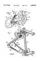
- FIG. 2is a partial perspective view of a portion of the rear suspension linkage system of the present invention.
- FIG. 3is an enlarged perspective view taken along line 3--3 of FIG. 2;
- FIG. 4is a perspective view of the shock absorber shown in FIGS. 2 and 3;
- FIG. 5is a side-elevational view of the rear suspension linkage system in the unactuated state.
- FIG. 6is a side elevational view of the rear suspension linkage system in the actuated state.
- FIG. 1perspectively illustrates a bicycle 10 incorporating a bicycle frame 12 constructed to incorporate the bicycle rear suspension linkage system of the present invention.
- the bicycle frame 12generally comprises a head tube 14 disposed at the front end of the bicycle 10 and a seat tube 16 disposed toward the rear end of the bicycle 10.
- a stem 18Connected to the top end of the head tube 14 is a stem 18 to which is attached the handle bars 20.
- a conventional front shock absorber assembly 22Connected to the bottom end of the stem 18 is a conventional front shock absorber assembly 22 defining a first fork 24 and a second fork 26 between which is mounted the axle 28 of the front wheel 30.
- the front shock absorber assembly 22is adapted to provide the compressive first fork 24 and compressive second fork 26 with shock absorbing capability.
- a seat post 32Telescopically received into the top end of the seat tube 16 is a seat post 32 having a saddle or seat 34 connected thereto.
- axle receiving bracket 38Rigidly attached to and extending between the head tube 14 and seat tube 16 is an elongate top tube 36. Additionally, rigidly attached to the bottom end of the seat tube 16 is an axle receiving bracket 38 having an axle-receiving bore 40 extending axially therethrough. In the preferred embodiment, the axle receiving bracket 38 has a generally cylindrical configuration and is attached to the lower end of the seat tube 16 via a brazed or welded connection. The bore 40 of the axle receiving bracket 38 is sized and configured to receive a bottom bracket axle of the bicycle 10. Attached to the opposed ends of the bottom bracket axle are a pair of cranks 42 to which are attached pedals 44.
- a chainwheel 46which is adapted to rotate concurrently with the bottom bracket axle.
- a chainwheel 46which is adapted to rotate concurrently with the bottom bracket axle.
- Rigidly attached to and extending between the head tube 14 and the axle receiving bracket 38is an elongate down tube 48.
- the head tube 14, top tube 36, axle receiving bracket 38, and down tube 48each have generally cylindrical configurations and are secured to one another via welded or brazed connections.
- link mount 50rigidly attached to the seat tube 16 and top tube 36 is a cylindrically configured link mount 50 defining a bore extending laterally therethrough.
- the link mount 50is attached to the seat tube 16 and top tube 36 via a welding or brazing process.
- the link mount 50is preferably attached to both the seat tube 16 and top tube 36 to provide the resultant bicycle frame 12 with greater structural integrity, it will be recognized that the link mount 50 may be attached solely to either the seat tube 16 or top tube 36.
- the upper link 52Pivotally connected to the link mount 50 is an upper link 52.
- the upper link 52defines a front pair of mounting ears 54, a back pair of mounting ears 56, and a central pair of mounting ears 58. Extending laterally through each pair of mounting ears 54, 56, 58 is a pair of coaxially aligned apertures.
- the upper link 52is pivotally connected to the link mount 50 by initially orienting the front pair of mounting ears 54 adjacent the opposed ends of the link mount 50, i.e. inserting the link mount 50 into the space defined between the front pair of mounting ears 54. In this respect, the distance separating the mounting ears 54 of the front pair is adapted to slidably accommodate the link mount 50.
- the link mount 50When the link mount 50 is properly positioned between the front pair of mounting ears 54, the pair of apertures disposed within the mounting ears 54 will be coaxially aligned with the bore of the link mount 50. Thereafter, a fastener 60 is inserted into the coaxially aligned apertures and bore thus pivotally connecting the upper link 52 to the link mount 50.
- the bicycle frame 12 of the present inventionfurther comprises a pair of identically configured seat stay members 62 which have upper ends rigidly attached to an elongate seat stay end housing 64 via a welding or brazing process.
- the seat stay end housing 64defines a bore extending laterally therethrough, and is pivotally connected to the upper link 52.
- the seat stay end housing 64is inserted into the space defined between the back pair of mounting ears 56 which are spaced from each other a distance sufficient to allow the seat stay end housing 64 to be slidably received therebetween.
- the end housing 64is oriented between the back pair of mounting ears 56 such that the apertures of the mounting ears 56 are coaxially aligned with the bore of the end housing 64.
- a fastener 66is extended through the coaxially aligned apertures and bore, thus pivotally securing the end housing 64, and hence the seat stay members 62, to the upper link 52.
- a fastener 66is extended through the coaxially aligned apertures and bore, thus pivotally securing the end housing 64, and hence the seat stay members 62, to the upper link 52.
- Rigidly attached to the lower ends of the seat stay members 62is a pair of rear wheel axle receiving members 68, one of which is adapted to accommodate a rear derailleur.
- the rear wheel axle receiving members 68are adapted to support the rear wheel axle 70 of the rear wheel 72 therebetween.
- Attached to one end of the rear wheel axle 70is a rear sprocket which is cooperatively engaged to the chainwheel 46 via a chain 74.
- the upper portions of the seat stay members 62are arcuately contoured, and bowed inwardly toward the seat tube 16 when the end housing 64 is pivotally connected to the upper link 52.
- Rigidly attached to the arcuately contoured portions of the seat stay members 62 in opposed relationis a pair of identically configured shock mounts 76 which are also directed inwardly toward the seat tube 16.
- the attachment of the shock mounts 76 and rear wheel axle receiving members 68 to the seat stay members 62is facilitated by a welding or brazing process.
- the bicycle frame 12further includes a pair of chain stay members 78 which have front ends rigidly attached to a chain stay end housing 80 via a welding or brazing process.
- the chain stay end housing 80defines a pair of mounting ears 82 which include a pair of coaxially aligned apertures extending laterally therethrough.
- a chain stay pivot mount 83Disposed within the lower portion of the seat tube 16 is a chain stay pivot mount 83 which is extended through a complimentary aperture extending laterally through the lower portion of the seat tube 16 and rigidly secured therewithin via a welding or brazing process.
- the mounting ears 82 of the chain stay end housing 80are separated from each other a distance sufficient to allow the opposed ends of the chain stay pivot mount 83 to be inserted into the space defined between the mounting ears 82.
- the end housing 80and more particularly the mounting ears 82, are preferably extended about the chain stay pivot mount 83 such that the apertures extending through the mounting ears 82 are coaxially aligned with an aperture extending laterally through the chain stay pivot mount 83.
- a fastener 84is extended through the coaxially aligned apertures, thus pivotally connecting the end housing 80, and hence the chain stay members 78, to the chain stay pivot mount 83.
- Rigidly attached to the back ends of the chain stay members 78 via a welding or brazing processis a pair of identically configured clevis members 86, each of which include a pair of juxtaposed end portions 88 having a pair of coaxially aligned apertures extending laterally therethrough.
- the rear wheel axle receiving members 68 attached to the lower ends of the seat stay members 62are pivotally connected to the clevis members 86 attached to the back ends of the chain stay members 78.
- the frontal portion of each rear wheel axle receiving member 68is inserted into the space defined between the end portions 88 of a respective clevis member 86.
- the end portions 88 of each clevis member 86are separated from each other a distance sufficient to allow the frontal portion of the rear wheel axle receiving member 68 to be slidably inserted therebetween.
- the frontal portion of the rear wheel axle receiving member 68is oriented within the clevis member 86 such that an aperture disposed therein is coaxially aligned with the pair of apertures extending laterally through the end portions 88 of the clevis member 86. Thereafter, fasteners such as pivot pins 90 are extended through the coaxially aligned apertures of the end portions 88 and rear wheel axle receiving members 68, thus pivotally connecting the rear wheel axle receiving members 68 to the clevis members 86, and hence the chain stay members 78.
- the shock absorber 92further comprises a helical spring member 106 disposed between the upper and lower spring retention members 100, 102 in a manner wherein the upper end of the spring member 106 abuts the inner surface of the upper spring retention member 100, the lower end of the spring member 106 abuts the inner surface of the lower spring retention member 102, and the piston rod 96 of the shock absorber 92 extends axially through the center of the spring member 106.
- the tension of the spring member 106and thus the force needed to reciprocate the piston rod 96, is adjustable via the selective placement of the upper spring retention member 100 on the threaded outer surface of the body portion 94.
- shock absorber 92and in particular the body portion 94 thereof, is preferably fluid-filled, with a suitable fluid being infused thereinto via an inlet-outlet valve 108 fluidly coupled to the upper coupling section 98.
- An elastomer bushing 99 of sufficient resiliencyis disposed about the piston rod 96 and attached to the inner surface of the lower spring retention member 102 to serve as a bump-stop for preventing metal-to-metal contact in the event the shock absorber 92 "bottoms-out".
- the upper coupling section 98 of the shock absorber 92is pivotally connected to the upper link 52.
- the upper coupling section 98is sized so as to be slidably receivable into the space defined between the central pair of mounting ears 58 of the upper link 52.
- the pair of apertures disposed within the mounting ears 58are coaxially aligned with an aperture 110 extending laterally through the upper coupling section 98.
- a fastenersuch as a pivot pin 112 is extended through the coaxially aligned mounting ear apertures and aperture 110, thus pivotally connecting the shock absorber 92 to the upper link 52.
- the lower coupling section 104In addition to the pivotal connection of the upper coupling section 98 to the upper link 52, the lower coupling section 104, and hence the piston rod 96, is pivotally connected to the seat stay members 62.
- the lower coupling section 104is positioned within the space defined between the shock mounts 76 rigidly attached to the seat stay members 92, and oriented such that the pair of apertures extending laterally through the shock mounts 76 are coaxially aligned with an aperture 114 extending laterally through the lower coupling section 104.
- a fastenersuch as a pivot pin 116 is extended through the coaxially aligned shock mount apertures and aperture 114, thus pivotally connecting the piston rod 96 to the seat stay members 62.
- shock absorber 92may be mounted between the upper link 52 and seat stay members 62 in a reverse orientation, with the lower coupling section 104 being positioned between and pivotally connected to the mounting ears 58 and the upper coupling section 98 being positioned between and pivotally connected to the shock mounts 76.
- the bicycle frame 12 constructed in the previously described manneressentially comprises a four bar linkage system.
- the main front triangle portion of the bicycle frame 12comprising the head tube 14, seat tube 16, top tube 36, axle receiving bracket 38 and down tube 48 defines the first link of the system (i.e. the ground link of the four bar linkage system), while the chain stay members 78 define the second link of the system.
- the seat stay members 62define the third link of the system, while the upper link 52 defines the fourth and final link of the four bar linkage system.
- the shock absorber 92"floats" since it is pivotally mounted to and extends between the third and fourth links of the linkage system, i.e. the seat stay members 62 and upper link 52, and is not rigidly mounted to the first link or ground link of the linkage system, i.e. the main front triangle portion of the bicycle frame 12.
- the shock absorberis mounted directly to the main front triangle portion of the bicycle frame, thus causing a shock force applied to the rear wheel of the bicycle to be transmitted directly to the main front triangle portion as a bending moment or torque.
- the transmission of bending moments or torque to the main front triangle portionresults in a less smooth ride over bumps or uneven terrain.
- the isolation of the shock absorber 92 from the main front triangle portion of the bicycle frame 12 and the pivotal connection of the upper link 52 and chain stay members 78 to the main front triangle portioneliminates the direct transmission of bending moments or torque to the main front triangle portion when the rear wheel 72 encounters bumps or other obstructions, thus enhancing the smoothness of the ride and the overall performance of the bicycle 10.
- the rear axle of the rear wheelpivots about a single elevated pivot point which typically causes the rear wheel axle to move arcuately rather than vertically in a substantially linear fashion. If the rear wheel axle moves in an arc, efficiency is lost due to suspension oscillations caused by changes in the bicycle wheelbase.
- the various components comprising the bicycle frame 12 of the present inventionare adapted to provide a suspension for the rear wheel 72 of the bicycle 10 which allows the rear wheel axle 70 to move vertically in a substantially linear fashion when the rear wheel 72 encounters a bump or other obstruction.
- the four bar linkage system defined by the bicycle frame 12causes the rear wheel axle 70 to be pivoted relative an instantaneous center of zero velocity or rotation, the location of which is optimized to balance the weight transfer (due to forward acceleration), with the chain force pulling the rear wheel axle 70 in a downward direction.
- the bicycle frame 12is not influenced by pedaling forces.
- the movement of the rear wheel axle receiving members 68 in the direction Aalso causes the chain stay members 78 to pivot upwardly about the center point of the fastener 84 in the direction D.
- the concurrent upward pivoting of the upper link 52 in the direction C, the planar motion of the seat stay members 62 in the direction B, and the upward pivotal movement of the chain stay members 78 in the direction Dcauses the rear wheel axle receiving members 68 and hence the rear wheel axle 70 to move generally vertically upwardly in the direction A when the rear wheel 72 is subjected to a shock force.
- the shock absorber 92Due to the placement of the shock absorber 92 between the upper link 52 and seat stay members 62, the upward pivotal movement of the upper link 52, seat stay members 62, rear wheel axle receiving members 68 and chain stay members 78 is controlled and limited thereby.
- the shock absorber 92is adapted to absorb some of the shock force exerted on the rear wheel 72 as such force is transmitted through the linkage assembly.
- the amount of the shock force absorbed by the shock absorber 92may be selectively adjusted via the positioning of the upper spring retention member 100 along the threaded outer surface of the body portion 94.
- the positioning of the upper spring retention member 100allows the spring preload to be adjusted, thus allowing for adjustments to static ride height, different rider weights and varying riding conditions.
- the mounting of the shock absorber 92 solely to the third and fourth links of the linkage system, i.e. to the upper link 52 and seat stay members 62,also eliminates the transmission of the shock force as bending moments to the main front triangle portion of the bicycle frame 12, thus enhancing the overall performance characteristics of the bicycle 10.
- this particular placement of the shock absorber 92serves to reinforce the primary in-line pivot of the four bar linkage system, i.e. the pivot point defined by the attachment of the seat stay end housing 64 to the upper link 52 via the fastener 66. Since, in most prior art rear suspension linkage systems, the primary pivot point of the linkage system is not reinforced by the shock absorber, the linkage system is more susceptible to mechanical failure.
- the ratio of movement, i.e. the motion ratio, between the rear wheel axle 70 in the direction A and the helical spring member 106 as it is being compressedis constant throughout the range of travel of the rear wheel axle 70, thus providing a relatively flat wheel rate when the rear wheel 72 encounters a shock or other obstruction.
- this flat wheel rateis more desirable than a regressive or progressive wheel rate wherein the shock travel and rear wheel axle travel are disproportionate.
Landscapes
- Engineering & Computer Science (AREA)
- Mechanical Engineering (AREA)
- Axle Suspensions And Sidecars For Cycles (AREA)
Abstract
Description
Claims (17)
Priority Applications (2)
| Application Number | Priority Date | Filing Date | Title |
|---|---|---|---|
| US08/121,783US5409249A (en) | 1993-09-15 | 1993-09-15 | Bicycle rear suspension system |
| US08/227,009US5441292A (en) | 1993-09-15 | 1994-04-13 | Bicycle rear suspension system |
Applications Claiming Priority (1)
| Application Number | Priority Date | Filing Date | Title |
|---|---|---|---|
| US08/121,783US5409249A (en) | 1993-09-15 | 1993-09-15 | Bicycle rear suspension system |
Related Child Applications (1)
| Application Number | Title | Priority Date | Filing Date |
|---|---|---|---|
| US08/227,009Continuation-In-PartUS5441292A (en) | 1993-09-15 | 1994-04-13 | Bicycle rear suspension system |
Publications (1)
| Publication Number | Publication Date |
|---|---|
| US5409249Atrue US5409249A (en) | 1995-04-25 |
Family
ID=22398759
Family Applications (1)
| Application Number | Title | Priority Date | Filing Date |
|---|---|---|---|
| US08/121,783Expired - LifetimeUS5409249A (en) | 1993-09-15 | 1993-09-15 | Bicycle rear suspension system |
Country Status (1)
| Country | Link |
|---|---|
| US (1) | US5409249A (en) |
Cited By (65)
| Publication number | Priority date | Publication date | Assignee | Title |
|---|---|---|---|---|
| WO1996007378A1 (en)* | 1994-09-09 | 1996-03-14 | University Of Toledo | Improved knee joint mechanism for knee disarticulation prosthesis |
| USD368880S (en) | 1994-09-09 | 1996-04-16 | Harrington Jeffrey M | Rear suspension portion of a bicycle frame |
| US5628524A (en)* | 1995-01-25 | 1997-05-13 | Outland Design Techologies, Inc. | Bicycle wheel travel path for selectively applying chainstay lengthening effect and apparatus for providing same |
| USD380990S (en)* | 1996-05-14 | 1997-07-15 | Percy Chien | Bicycle frame |
| US5678837A (en)* | 1992-01-21 | 1997-10-21 | Leitner; Horst | Rear suspension for bicycles |
| US5720491A (en)* | 1996-03-25 | 1998-02-24 | Harper; Bruce M. | Light-weight cycle suspension |
| WO1998018671A1 (en)* | 1996-10-28 | 1998-05-07 | Kramer Massow Klaus | Two wheeled vehicle, especially a bicycle |
| US5797613A (en)* | 1996-06-14 | 1998-08-25 | Gt Bicycles, Inc. | Bicycle flex joint |
| US5826899A (en)* | 1996-07-03 | 1998-10-27 | Klein Bicycle Corporation | High performance suspension bicycle frameset |
| FR2762572A1 (en)* | 1997-04-25 | 1998-10-30 | Renault Sport | REAR SUSPENSION FOR BICYCLE |
| WO1999010224A1 (en)* | 1997-08-29 | 1999-03-04 | Schwinn Cycling & Fitness Inc. | Rear suspension for a bicycle |
| US5909890A (en)* | 1996-09-11 | 1999-06-08 | Sachs; Gregory D. | Device for locking and unlocking bicycle suspension systems |
| US5947499A (en)* | 1996-06-14 | 1999-09-07 | Gt Bicycles, Inc. | Bicycle flexible joint |
| US5957473A (en)* | 1996-03-15 | 1999-09-28 | Schwinn Cycling & Fitness Inc. | Rear suspension bicycle |
| WO1999048711A1 (en)* | 1998-03-27 | 1999-09-30 | Schonfeld Carl W | Torsional shock absorber for bicycle |
| US5997022A (en)* | 1997-07-02 | 1999-12-07 | Shimano Inc. | Bicycle suspension assembly |
| US6029990A (en)* | 1997-05-13 | 2000-02-29 | Gt Bicycles, Inc. | Direct drive bicycle |
| US6073950A (en)* | 1997-10-28 | 2000-06-13 | Busby; James S. | Bicycle with crank assembly suspension system |
| US6076845A (en)* | 1998-09-24 | 2000-06-20 | Schwinn Cycling & Fitness Inc. | Rear suspension for a bicycle having a flexible chain stay |
| US6099010A (en)* | 1997-10-28 | 2000-08-08 | Gt Bicycles, Inc. | Bicycle with crank assembly suspension system |
| US6149175A (en)* | 1998-12-18 | 2000-11-21 | Shimano Inc. | Bicycle suspension |
| US6164676A (en)* | 1998-02-20 | 2000-12-26 | Trek Bicycle Corporation | Variable reduction cross-linkage for rear suspension bicycle |
| US6199886B1 (en) | 1997-03-14 | 2001-03-13 | Peter Guenther | Rear suspension system for bicycle |
| US6203042B1 (en) | 1998-02-20 | 2001-03-20 | Trek Bicycle Corporation | Bicycle rear suspension system providing relative rearward motion of rear axle |
| US6206397B1 (en)* | 1995-01-25 | 2001-03-27 | James B. Klassen | Bicycle wheel travel path for selectively applying chainstay lengthening effect and apparatus for providing same |
| AU737639B2 (en)* | 1997-03-14 | 2001-08-23 | Peter Guenther | Rear suspension system for bicycle |
| US6378885B1 (en) | 1998-03-02 | 2002-04-30 | Anthony S. Ellsworth | Bicycle suspension apparatus and related method |
| FR2821603A1 (en)* | 2001-03-01 | 2002-09-06 | Philippe Lesage | ANTI-PUMPING SYSTEM OF A WHEELED VEHICLE WHOSE TORQUE IS DRIVEN BY A DRIVE CHAIN TO THE DRIVE WHEEL CARRIED BY AN OSCILLATING ARM |
| WO2003018392A1 (en) | 2001-08-22 | 2003-03-06 | Rocky Mountain Bicycles, A Division Of Procycle Group Inc. | Rear suspension system for two-wheeled vehicles, particularly bicycles |
| EP1352823A3 (en)* | 2002-04-10 | 2005-02-09 | Derby Cycle Werke GmbH | Two-wheel frame, in particular for a bicycle |
| US20050067810A1 (en)* | 2003-09-25 | 2005-03-31 | David Weagle | Bicycle suspension systems |
| US20050167801A1 (en)* | 2004-02-04 | 2005-08-04 | Kerr Daniel C. | Structure and method for improved heat conduction for semiconductor devices |
| US20050184483A1 (en)* | 2003-12-12 | 2005-08-25 | Noel Buckley | Rear suspension system for bicycles |
| US20060022429A1 (en)* | 1998-03-02 | 2006-02-02 | Anthony S. Ellsworth | Bicycle suspension apparatus and related method |
| US7066481B1 (en) | 2005-04-13 | 2006-06-27 | Felt Racing, Llc | Bicycle rear suspension |
| USRE39159E1 (en)* | 1995-01-25 | 2006-07-11 | Santa Cruz Bicycles, Inc. | Bicycle wheel travel path for selectively applying chainstay lengthening effect and apparatus for providing same |
| US20060225942A1 (en)* | 2005-04-07 | 2006-10-12 | David Weagle | Vehicle suspension system for stable squat magnitude responses |
| US7222870B2 (en) | 2004-11-24 | 2007-05-29 | Shimano Inc. | Bicycle suspension assembly |
| WO2007104795A1 (en)* | 2006-03-15 | 2007-09-20 | Cycles Lapierre | Bicycle rear suspension |
| FR2898578A1 (en)* | 2006-03-15 | 2007-09-21 | Cycles Lapierre Soc Par Action | Rear suspension system for e.g. bicycle, has arm pivoting around center of rotation when hub is displaced on both sides of reference position corresponding to position of axle, where trajectory of center of rotation is extended behind axle |
| US20080067772A1 (en)* | 2006-08-25 | 2008-03-20 | David Weagle | Vehicle suspension systems for seperated acceleration responses |
| US20090001685A1 (en)* | 2007-06-29 | 2009-01-01 | Specialized Bicycle Components, Inc. | Bicycle frame |
| US20090001686A1 (en)* | 2007-06-28 | 2009-01-01 | Currie Christopher S | Rear wheel suspension system for a two-wheeled vehicle |
| US20090026728A1 (en)* | 2007-07-27 | 2009-01-29 | Niner, Inc. | Bicycle rear suspension |
| USD593457S1 (en) | 2007-06-29 | 2009-06-02 | Specialized Bicycle Components, Inc. | Bicycle frame |
| DE102008008186A1 (en)* | 2008-02-08 | 2009-08-27 | Canyon Bicycles Gmbh | Bicycle frame i.e. mountain bike frame, has spring-loaded body rear end including chain stays that are pivotably connected with main frame element and have articulation element in central area between housing and dropout end |
| US20090315296A1 (en)* | 2008-06-20 | 2009-12-24 | Kona Usa, Inc. | Suspension for mountain bicycles |
| US20100102531A1 (en)* | 2005-11-14 | 2010-04-29 | Santa Cruz Bicycles, Inc. | Bicycle rear suspension system with controlled variable shock rate |
| US20100109282A1 (en)* | 2008-09-16 | 2010-05-06 | David Weagle | Bicycle suspension systems |
| CN101296839B (en)* | 2005-01-19 | 2010-10-13 | 雷诺体育技术公司 | Rear fork for bicycle |
| US20110233892A1 (en)* | 2007-07-27 | 2011-09-29 | Niner, Inc. | Bicycle Rear Suspension |
| WO2011142983A1 (en)* | 2010-05-14 | 2011-11-17 | Specialized Bicycle Components, Inc. | Seatstay suspension mount |
| US8272658B2 (en) | 2004-09-15 | 2012-09-25 | Yeti Cycling, Llc | Rear suspension system for a bicycle |
| WO2016134471A1 (en)* | 2015-02-27 | 2016-09-01 | Cmh Plus Holdings Ltd. | Rear suspension system for a bicycle |
| US9561834B2 (en) | 2010-08-20 | 2017-02-07 | Yeti Cycling, Llc | Link suspension system |
| US9821879B2 (en) | 2010-08-20 | 2017-11-21 | Yeti Cycling, Llc | Reciprocating rail movement suspension system |
| US9981711B2 (en)* | 2016-08-22 | 2018-05-29 | Big Cat Human Powered Vehicles, Llc | Suspended spindle assembly for recumbent tricyles |
| US10766563B2 (en) | 2013-01-16 | 2020-09-08 | Yeti Cyclying, Llc | Rail suspension with integral shock and dampening mechanism |
| US10926830B2 (en) | 2017-07-07 | 2021-02-23 | Yeti Cycling, Llc | Vehicle suspension linkage |
| US11040754B2 (en) | 2019-01-18 | 2021-06-22 | Sram, Llc | Dampers for bicycle suspension components |
| US11173983B2 (en) | 2017-03-17 | 2021-11-16 | Yeti Cycling, Llc | Vehicle suspension linkage |
| USD958702S1 (en) | 2020-08-05 | 2022-07-26 | Specialized Bicycle Components, Inc. | Bicycle frame |
| US12077241B2 (en) | 2019-02-01 | 2024-09-03 | Yeti Cycling, Llc | Multi-body vehicle suspension linkage |
| US12145684B2 (en) | 2019-12-24 | 2024-11-19 | Yeti Cycling, Llc | Constrained multiple instantaneous velocity center linkage assembly for vehicle suspension |
| US12384484B2 (en) | 2020-11-18 | 2025-08-12 | Yeti Cycling, Llc | Integrated motor mount and suspension pivot |
Citations (27)
| Publication number | Priority date | Publication date | Assignee | Title |
|---|---|---|---|---|
| US439095A (en)* | 1890-10-28 | Hugo auguste becker | ||
| US578615A (en)* | 1897-03-09 | Bicycle | ||
| US606323A (en)* | 1898-06-28 | wronski | ||
| US657667A (en)* | 1899-12-09 | 1900-09-11 | Virgel H Mills | Bicycle-frame. |
| US944795A (en)* | 1908-08-21 | 1909-12-28 | Edward H Leet | Frame for motor-cycles, bicycles, and the like. |
| US1047430A (en)* | 1912-01-09 | 1912-12-17 | Minneapolis Motor Company | Motor-cycle frame. |
| GB191515332A (en)* | 1915-11-01 | 1916-09-21 | Claudius William Pidcock | Improvements in Shock-absorbing Devices for the Frames of Motor-cycles and the like. |
| US1257761A (en)* | 1915-06-28 | 1918-02-26 | Andrew Strand | Motor-cycle frame. |
| US1298958A (en)* | 1917-10-11 | 1919-04-01 | William Johnston | Bicycle-frame. |
| US1412012A (en)* | 1913-04-05 | 1922-04-04 | Bruno Carlo | Springing suspension device for cycles |
| GB220760A (en)* | 1923-06-21 | 1924-08-28 | Harry Topham Short | Improvements in or relating to the rear spring suspension of motor cycles, cycles and the like |
| US1594079A (en)* | 1925-01-28 | 1926-07-27 | Tanner William Mostyn | Resilient suspension means for motor cycles |
| US3917313A (en)* | 1973-12-17 | 1975-11-04 | Bultaco Compania Espanola Espa | Motorcycle suspension system |
| DE3033294A1 (en)* | 1979-09-12 | 1981-04-02 | Alberto Martorellas Barcelona Pous Quilez | BICYCLE |
| US4322088A (en)* | 1979-02-13 | 1982-03-30 | Honda Giken Kogyo Kabushiki Kaisha | Rear wheel suspension for a motorcycle |
| US4506755A (en)* | 1981-12-11 | 1985-03-26 | Honda Motor Co Ltd | Rear suspension system for motorcycles |
| US4529056A (en)* | 1982-09-24 | 1985-07-16 | Ceske Zavody Motocyklove, Narodni Podnik | Mechanism for the spring-cushioning of a vehicle wheel |
| US4673053A (en)* | 1984-09-21 | 1987-06-16 | Honda Giken Kogyo Kabushiki Kaisha | Frame-rear suspension assembly for a motorcycle and the like |
| US4789174A (en)* | 1987-04-27 | 1988-12-06 | Mert Lawwill | Suspension bicycle |
| US4951791A (en)* | 1987-02-20 | 1990-08-28 | Belil Creixelli Jose L | Rear wheel suspension mechanism for motorcycles and the like vehicles |
| US4997197A (en)* | 1989-05-08 | 1991-03-05 | Shultz G Merle | Soft suspension bicycle |
| US5098114A (en)* | 1990-09-18 | 1992-03-24 | Jones Gwyndaf M | Pivotless human-powered vehicle suspension system |
| US5121937A (en)* | 1990-12-13 | 1992-06-16 | Mert Lawwill | Suspension bicycle |
| US5205572A (en)* | 1991-08-27 | 1993-04-27 | Schwinn Bicycle Company | Cycle rear suspension system |
| US5244224A (en)* | 1992-05-14 | 1993-09-14 | Gt Bicycles, Inc. | Rocker arm rear suspension bicycle |
| US5259637A (en)* | 1993-01-13 | 1993-11-09 | Gt Bicycles, Inc. | Bicycle rear suspension |
| US5335929A (en)* | 1992-06-17 | 1994-08-09 | Miyata Industry Co., Ltd. | Bicycle frame |
- 1993
- 1993-09-15USUS08/121,783patent/US5409249A/ennot_activeExpired - Lifetime
Patent Citations (27)
| Publication number | Priority date | Publication date | Assignee | Title |
|---|---|---|---|---|
| US439095A (en)* | 1890-10-28 | Hugo auguste becker | ||
| US578615A (en)* | 1897-03-09 | Bicycle | ||
| US606323A (en)* | 1898-06-28 | wronski | ||
| US657667A (en)* | 1899-12-09 | 1900-09-11 | Virgel H Mills | Bicycle-frame. |
| US944795A (en)* | 1908-08-21 | 1909-12-28 | Edward H Leet | Frame for motor-cycles, bicycles, and the like. |
| US1047430A (en)* | 1912-01-09 | 1912-12-17 | Minneapolis Motor Company | Motor-cycle frame. |
| US1412012A (en)* | 1913-04-05 | 1922-04-04 | Bruno Carlo | Springing suspension device for cycles |
| US1257761A (en)* | 1915-06-28 | 1918-02-26 | Andrew Strand | Motor-cycle frame. |
| GB191515332A (en)* | 1915-11-01 | 1916-09-21 | Claudius William Pidcock | Improvements in Shock-absorbing Devices for the Frames of Motor-cycles and the like. |
| US1298958A (en)* | 1917-10-11 | 1919-04-01 | William Johnston | Bicycle-frame. |
| GB220760A (en)* | 1923-06-21 | 1924-08-28 | Harry Topham Short | Improvements in or relating to the rear spring suspension of motor cycles, cycles and the like |
| US1594079A (en)* | 1925-01-28 | 1926-07-27 | Tanner William Mostyn | Resilient suspension means for motor cycles |
| US3917313A (en)* | 1973-12-17 | 1975-11-04 | Bultaco Compania Espanola Espa | Motorcycle suspension system |
| US4322088A (en)* | 1979-02-13 | 1982-03-30 | Honda Giken Kogyo Kabushiki Kaisha | Rear wheel suspension for a motorcycle |
| DE3033294A1 (en)* | 1979-09-12 | 1981-04-02 | Alberto Martorellas Barcelona Pous Quilez | BICYCLE |
| US4506755A (en)* | 1981-12-11 | 1985-03-26 | Honda Motor Co Ltd | Rear suspension system for motorcycles |
| US4529056A (en)* | 1982-09-24 | 1985-07-16 | Ceske Zavody Motocyklove, Narodni Podnik | Mechanism for the spring-cushioning of a vehicle wheel |
| US4673053A (en)* | 1984-09-21 | 1987-06-16 | Honda Giken Kogyo Kabushiki Kaisha | Frame-rear suspension assembly for a motorcycle and the like |
| US4951791A (en)* | 1987-02-20 | 1990-08-28 | Belil Creixelli Jose L | Rear wheel suspension mechanism for motorcycles and the like vehicles |
| US4789174A (en)* | 1987-04-27 | 1988-12-06 | Mert Lawwill | Suspension bicycle |
| US4997197A (en)* | 1989-05-08 | 1991-03-05 | Shultz G Merle | Soft suspension bicycle |
| US5098114A (en)* | 1990-09-18 | 1992-03-24 | Jones Gwyndaf M | Pivotless human-powered vehicle suspension system |
| US5121937A (en)* | 1990-12-13 | 1992-06-16 | Mert Lawwill | Suspension bicycle |
| US5205572A (en)* | 1991-08-27 | 1993-04-27 | Schwinn Bicycle Company | Cycle rear suspension system |
| US5244224A (en)* | 1992-05-14 | 1993-09-14 | Gt Bicycles, Inc. | Rocker arm rear suspension bicycle |
| US5335929A (en)* | 1992-06-17 | 1994-08-09 | Miyata Industry Co., Ltd. | Bicycle frame |
| US5259637A (en)* | 1993-01-13 | 1993-11-09 | Gt Bicycles, Inc. | Bicycle rear suspension |
Non-Patent Citations (32)
| Title |
|---|
| 1992 Cannondale Spec Suspension Mountain Bicycles Article 10 pages.* |
| 1992 Cannondale Spec-Suspension Mountain Bicycles-Article-10 pages. |
| Bicycling, Nov. 1992, pp. 26 27, 58, 63 64, and 105.* |
| Bicycling, Nov. 1992, pp. 26-27, 58, 63-64, and 105. |
| Boulder Intrepid AL 2 pages Mountain Bike Action/Mar. 92.* |
| Boulder Intrepid AL-2 pages-Mountain Bike Action/Mar. '92. |
| Fisher RS 1 Article 4 pages. Mountain Bike Action/Mar. 92.* |
| Fisher RS-1-Article-4 pages.-Mountain Bike Action/Mar. '92. |
| Guide to Suspension and High Performance, vol. 3, 1992, pp. 9, 13 15, 17, 30 31, 36 37, 42 45, 47, 53, 60, 69, 71, 76, 85 87, 92, 96, 98, 100, 108 112, 117 and 119.* |
| Guide to Suspension and High Performance, vol. 3, 1992, pp. 9, 13-15, 17, 30-31, 36-37, 42-45, 47, 53, 60, 69, 71, 76, 85-87, '92, 96, 98, 100, 108-112, 117 and 119. |
| If the Best Motorcycle . . . "Litespeed Suspension", Mountain Bike-Jul. '92 8 pages. |
| If the Best Motorcycle . . . Litespeed Suspension , Mountain Bike Jul. 92 8 pages.* |
| Mountain Bike Action, Oct. 1992, pp. 10, 25 26, 28 29, 31, 36 37, 39 41, 44 45, 47, 58, 70, 73, 76, 79, 123, and 130.* |
| Mountain Bike Action, Oct. 1992, pp. 10, 25-26, 28-29, 31, 36-37, 39-41, 44-45, 47, 58, 70, 73, 76, 79, 123, and 130. |
| Mountain Biking, Nov. 1992, vol. 6, No. 11, pp. 6 9, 25, 48 49, 65, 71, 73, 108 109, 115, 124, 129, 140, 143, 163, and 169.* |
| Mountain Biking, Nov. 1992, vol. 6, No. 11, pp. 6-9, 25, 48-49, 65, 71, 73, 108-109, 115, 124, 129, 140, 143, 163, and 169. |
| Moutain Biking, Dec. 92, pp. 1 2, 5, 18, 44 49, 77, 127, and 160.* |
| Moutain Biking, Dec. '92, pp. 1-2, 5, 18, 44-49, 77, 127, and 160. |
| Moutain Biking, Jan. 93, vol. 7, No. 1, pp. 32 33, 40, 45, 71, 75, 82 83, 115, and 117.* |
| Moutain Biking, Jan. '93, vol. 7, No. 1, pp. 32-33, 40, 45, 71, 75, 82-83, 115, and 117. |
| Offroad Pro Flex 550 3 pages. Offroad.* |
| Offroad Pro-Flex 550-3 pages.-Offroad. |
| Slingshot Mountain & City Biking, 6 pages.* |
| Slingshot-Mountain & City Biking, 6 pages. |
| Suspension Mania Strikes Cycling Mountain Bike Action/Feb. 92 3 pages.* |
| Suspension Mania Strikes Cycling-Mountain Bike Action/Feb. '92 3 pages. |
| Team Shockblok 6 pages. Mountain Bike Action/Jul. 92.* |
| Team Shockblok-6 pages.-Mountain Bike Action/Jul. '92. |
| TREK 9000 Series Spec This Beauty Is A Beast Article 8 pages.* |
| TREK 9000 Series Spec="This Beauty Is A Beast"-Article-8 pages. |
| Welcome to the Next Generation . . . 9 pages. Mountain Bike Jun. 92 Schwinn S.A.S.S. 7 pages. Mountain Bike Action May 92.* |
| Welcome to the Next Generation . . . -9 pages.-Mountain Bike-Jun. '92 Schwinn S.A.S.S.-7 pages.-Mountain Bike Action-May'92. |
Cited By (126)
| Publication number | Priority date | Publication date | Assignee | Title |
|---|---|---|---|---|
| US5678837A (en)* | 1992-01-21 | 1997-10-21 | Leitner; Horst | Rear suspension for bicycles |
| USD368880S (en) | 1994-09-09 | 1996-04-16 | Harrington Jeffrey M | Rear suspension portion of a bicycle frame |
| GB2307415A (en)* | 1994-09-09 | 1997-05-28 | Univ Toledo | Improved knee joint mechanism for knee disarticulation prosthesis |
| GB2307415B (en)* | 1994-09-09 | 1998-08-12 | Univ Toledo | Improved knee joint mechanism for knee disarticulation prosthesis |
| WO1996007378A1 (en)* | 1994-09-09 | 1996-03-14 | University Of Toledo | Improved knee joint mechanism for knee disarticulation prosthesis |
| US5628524A (en)* | 1995-01-25 | 1997-05-13 | Outland Design Techologies, Inc. | Bicycle wheel travel path for selectively applying chainstay lengthening effect and apparatus for providing same |
| US6206397B1 (en)* | 1995-01-25 | 2001-03-27 | James B. Klassen | Bicycle wheel travel path for selectively applying chainstay lengthening effect and apparatus for providing same |
| USRE39159E1 (en)* | 1995-01-25 | 2006-07-11 | Santa Cruz Bicycles, Inc. | Bicycle wheel travel path for selectively applying chainstay lengthening effect and apparatus for providing same |
| US5957473A (en)* | 1996-03-15 | 1999-09-28 | Schwinn Cycling & Fitness Inc. | Rear suspension bicycle |
| US6102421A (en)* | 1996-03-15 | 2000-08-15 | Schwinn Cycling & Fitness Inc. | Rear suspension for a bicycle |
| US5720491A (en)* | 1996-03-25 | 1998-02-24 | Harper; Bruce M. | Light-weight cycle suspension |
| USD380990S (en)* | 1996-05-14 | 1997-07-15 | Percy Chien | Bicycle frame |
| US5947499A (en)* | 1996-06-14 | 1999-09-07 | Gt Bicycles, Inc. | Bicycle flexible joint |
| US5865456A (en)* | 1996-06-14 | 1999-02-02 | Gt Bicycles, Inc. | Bicycle flex joint with non-torsional encasement |
| US5797613A (en)* | 1996-06-14 | 1998-08-25 | Gt Bicycles, Inc. | Bicycle flex joint |
| US5826899A (en)* | 1996-07-03 | 1998-10-27 | Klein Bicycle Corporation | High performance suspension bicycle frameset |
| US5909890A (en)* | 1996-09-11 | 1999-06-08 | Sachs; Gregory D. | Device for locking and unlocking bicycle suspension systems |
| WO1998018671A1 (en)* | 1996-10-28 | 1998-05-07 | Kramer Massow Klaus | Two wheeled vehicle, especially a bicycle |
| US6244610B1 (en) | 1996-10-28 | 2001-06-12 | Klaus Kramer-Massow | Two wheeled vehicle, especially a bicycle |
| US6199886B1 (en) | 1997-03-14 | 2001-03-13 | Peter Guenther | Rear suspension system for bicycle |
| AU737639B2 (en)* | 1997-03-14 | 2001-08-23 | Peter Guenther | Rear suspension system for bicycle |
| US6386568B1 (en) | 1997-04-25 | 2002-05-14 | Renault Sport | Bicycle rear suspension |
| FR2762572A1 (en)* | 1997-04-25 | 1998-10-30 | Renault Sport | REAR SUSPENSION FOR BICYCLE |
| WO1998049046A1 (en)* | 1997-04-25 | 1998-11-05 | Renault Sport | Bicycle rear suspension |
| US6029990A (en)* | 1997-05-13 | 2000-02-29 | Gt Bicycles, Inc. | Direct drive bicycle |
| US6079726A (en)* | 1997-05-13 | 2000-06-27 | Gt Bicycles, Inc. | Direct drive bicycle |
| US6155585A (en)* | 1997-05-13 | 2000-12-05 | Busby; James S. | Direct drive bicycle |
| US5997022A (en)* | 1997-07-02 | 1999-12-07 | Shimano Inc. | Bicycle suspension assembly |
| WO1999010224A1 (en)* | 1997-08-29 | 1999-03-04 | Schwinn Cycling & Fitness Inc. | Rear suspension for a bicycle |
| US6073950A (en)* | 1997-10-28 | 2000-06-13 | Busby; James S. | Bicycle with crank assembly suspension system |
| US6099010A (en)* | 1997-10-28 | 2000-08-08 | Gt Bicycles, Inc. | Bicycle with crank assembly suspension system |
| US6164676A (en)* | 1998-02-20 | 2000-12-26 | Trek Bicycle Corporation | Variable reduction cross-linkage for rear suspension bicycle |
| US6203042B1 (en) | 1998-02-20 | 2001-03-20 | Trek Bicycle Corporation | Bicycle rear suspension system providing relative rearward motion of rear axle |
| US6595538B2 (en) | 1998-03-02 | 2003-07-22 | Anthony S. Ellsworth | Bicycle suspension apparatus and related method |
| US6926298B2 (en) | 1998-03-02 | 2005-08-09 | Anthony S. Ellsworth | Bicycle suspension apparatus and related method |
| US6378885B1 (en) | 1998-03-02 | 2002-04-30 | Anthony S. Ellsworth | Bicycle suspension apparatus and related method |
| US20060022429A1 (en)* | 1998-03-02 | 2006-02-02 | Anthony S. Ellsworth | Bicycle suspension apparatus and related method |
| US7296815B2 (en) | 1998-03-02 | 2007-11-20 | Anthony S. Ellsworth | Bicycle suspension apparatus and related method |
| US20040145149A1 (en)* | 1998-03-02 | 2004-07-29 | Anthony S. Ellsworth | Bicycle suspension apparatus and related method |
| US6471230B2 (en) | 1998-03-02 | 2002-10-29 | Anthony S. Ellsworth | Bicycle suspension apparatus and related method |
| US5975550A (en)* | 1998-03-27 | 1999-11-02 | Schonfeld; Carl W. | Torsional shock absorber for bicycle |
| WO1999048711A1 (en)* | 1998-03-27 | 1999-09-30 | Schonfeld Carl W | Torsional shock absorber for bicycle |
| US6076845A (en)* | 1998-09-24 | 2000-06-20 | Schwinn Cycling & Fitness Inc. | Rear suspension for a bicycle having a flexible chain stay |
| US6149175A (en)* | 1998-12-18 | 2000-11-21 | Shimano Inc. | Bicycle suspension |
| US6834877B2 (en) | 2001-03-01 | 2004-12-28 | Philippe Lesage | Rear suspension of a vehicle with drive wheel borne by an oscillating arm |
| FR2821603A1 (en)* | 2001-03-01 | 2002-09-06 | Philippe Lesage | ANTI-PUMPING SYSTEM OF A WHEELED VEHICLE WHOSE TORQUE IS DRIVEN BY A DRIVE CHAIN TO THE DRIVE WHEEL CARRIED BY AN OSCILLATING ARM |
| WO2002070332A1 (en)* | 2001-03-01 | 2002-09-12 | Philippe Lesage | Rear suspension of a vehicle with drive wheel borne by an oscillating arm |
| US20040070169A1 (en)* | 2001-03-01 | 2004-04-15 | Philippe Lesage | Rear suspension of a vehicle with drive wheel borne by an oscillating arm |
| WO2003018392A1 (en) | 2001-08-22 | 2003-03-06 | Rocky Mountain Bicycles, A Division Of Procycle Group Inc. | Rear suspension system for two-wheeled vehicles, particularly bicycles |
| EP1352823A3 (en)* | 2002-04-10 | 2005-02-09 | Derby Cycle Werke GmbH | Two-wheel frame, in particular for a bicycle |
| US20050067810A1 (en)* | 2003-09-25 | 2005-03-31 | David Weagle | Bicycle suspension systems |
| US20050067806A1 (en)* | 2003-09-25 | 2005-03-31 | David Weagle | Vehicle suspension systems |
| US7128329B2 (en) | 2003-09-25 | 2006-10-31 | David Weagle | Vehicle suspension systems |
| US7048292B2 (en) | 2003-09-25 | 2006-05-23 | David Weagle | Bicycle suspension systems |
| US20060119070A1 (en)* | 2003-09-25 | 2006-06-08 | David Weagle | Bicycle suspension systems |
| US7828314B2 (en) | 2003-09-25 | 2010-11-09 | Dw-Link Incorporated | Vehicle suspension systems |
| US20070024022A1 (en)* | 2003-09-25 | 2007-02-01 | David Weagle | Vehicle suspension systems |
| US7467803B2 (en) | 2003-12-12 | 2008-12-23 | Noel Buckley | Rear suspension system for bicycles |
| US8646797B2 (en) | 2003-12-12 | 2014-02-11 | Noel Buckley | Rear suspension system for bicycles |
| US7980579B2 (en) | 2003-12-12 | 2011-07-19 | Noel Buckley | Rear suspension system for bicycles |
| US11919602B2 (en) | 2003-12-12 | 2024-03-05 | Knolly Bikes, Inc. | Rear suspension system for bicycles |
| US20110233893A1 (en)* | 2003-12-12 | 2011-09-29 | Noel Buckley | Rear suspension system for bicycles |
| US11845510B2 (en) | 2003-12-12 | 2023-12-19 | Knolly Bikes, Inc. | Rear suspension system for bicycles |
| US20050184483A1 (en)* | 2003-12-12 | 2005-08-25 | Noel Buckley | Rear suspension system for bicycles |
| US11312447B2 (en) | 2003-12-12 | 2022-04-26 | Knolly Bikes, Inc. | Rear suspension system for bicycles |
| US10363988B2 (en) | 2003-12-12 | 2019-07-30 | 668598 B.C. Ltd. | Rear suspension system for bicycles |
| US20080258427A1 (en)* | 2003-12-12 | 2008-10-23 | Noel Buckley | Rear suspension system for bicycles |
| US20050167801A1 (en)* | 2004-02-04 | 2005-08-04 | Kerr Daniel C. | Structure and method for improved heat conduction for semiconductor devices |
| US10293881B2 (en) | 2004-09-15 | 2019-05-21 | Yeti Cycling, Llc | Rear suspension system for a bicycle |
| US9221513B2 (en) | 2004-09-15 | 2015-12-29 | Yeti Cycling, Llc | Rear suspension system for a bicycle |
| US8696008B2 (en) | 2004-09-15 | 2014-04-15 | Yeti Cycling, Llc | Rear suspension system for a bicycle |
| US8272658B2 (en) | 2004-09-15 | 2012-09-25 | Yeti Cycling, Llc | Rear suspension system for a bicycle |
| US7222870B2 (en) | 2004-11-24 | 2007-05-29 | Shimano Inc. | Bicycle suspension assembly |
| CN101296839B (en)* | 2005-01-19 | 2010-10-13 | 雷诺体育技术公司 | Rear fork for bicycle |
| US20060225942A1 (en)* | 2005-04-07 | 2006-10-12 | David Weagle | Vehicle suspension system for stable squat magnitude responses |
| US7661503B2 (en) | 2005-04-07 | 2010-02-16 | Orion Dynamics, Inc. | Vehicle suspension system for stable squat magnitude responses |
| US7066481B1 (en) | 2005-04-13 | 2006-06-27 | Felt Racing, Llc | Bicycle rear suspension |
| US8733774B2 (en) | 2005-11-14 | 2014-05-27 | Santa Cruz Bicycles, Inc. | Bicycle rear suspension system with controlled variable shock rate |
| US8641072B2 (en) | 2005-11-14 | 2014-02-04 | Santa Cruz Bicycles, Inc. | Bicycle rear suspension system with controlled variable shock rate |
| US20100102531A1 (en)* | 2005-11-14 | 2010-04-29 | Santa Cruz Bicycles, Inc. | Bicycle rear suspension system with controlled variable shock rate |
| US8272657B2 (en) | 2005-11-14 | 2012-09-25 | Santa Cruz Bicycles, Inc. | Bicycle rear suspension system with controlled variable shock rate |
| FR2898578A1 (en)* | 2006-03-15 | 2007-09-21 | Cycles Lapierre Soc Par Action | Rear suspension system for e.g. bicycle, has arm pivoting around center of rotation when hub is displaced on both sides of reference position corresponding to position of axle, where trajectory of center of rotation is extended behind axle |
| AU2007224443B2 (en)* | 2006-03-15 | 2013-04-04 | Cycles Lapierre | Bicycle rear suspension |
| US8857842B2 (en) | 2006-03-15 | 2014-10-14 | Emmanuel Antonot | Bicycle rear suspension |
| FR2898577A1 (en)* | 2006-03-15 | 2007-09-21 | Cycles Lapierre Soc Par Action | IMPROVEMENT TO A REAR SUSPENSION OF A VEHICLE |
| WO2007104795A1 (en)* | 2006-03-15 | 2007-09-20 | Cycles Lapierre | Bicycle rear suspension |
| US20090102158A1 (en)* | 2006-03-15 | 2009-04-23 | Emmanuel Antonot | Bicycle Rear Suspension |
| CN101400565B (en)* | 2006-03-15 | 2012-08-29 | 拉皮埃尔自行车公司 | bicycle rear suspension |
| US7717212B2 (en) | 2006-08-25 | 2010-05-18 | Split Pivot, Inc. | Vehicle suspension systems for seperated acceleration responses |
| US8002301B2 (en) | 2006-08-25 | 2011-08-23 | Split Pivot, Inc. | Vehicle suspension systems for seperated acceleration responses |
| US20080073868A1 (en)* | 2006-08-25 | 2008-03-27 | David Weagle | Vehicle suspension systems for seperated acceleration responses |
| US20080067772A1 (en)* | 2006-08-25 | 2008-03-20 | David Weagle | Vehicle suspension systems for seperated acceleration responses |
| US20090001686A1 (en)* | 2007-06-28 | 2009-01-01 | Currie Christopher S | Rear wheel suspension system for a two-wheeled vehicle |
| US7815207B2 (en) | 2007-06-28 | 2010-10-19 | Currie Christopher S | Rear wheel suspension system for a two-wheeled vehicle |
| US20090001685A1 (en)* | 2007-06-29 | 2009-01-01 | Specialized Bicycle Components, Inc. | Bicycle frame |
| USD593457S1 (en) | 2007-06-29 | 2009-06-02 | Specialized Bicycle Components, Inc. | Bicycle frame |
| US8590914B2 (en) | 2007-07-27 | 2013-11-26 | Niner, Inc. | Bicycle rear suspension |
| US20090026728A1 (en)* | 2007-07-27 | 2009-01-29 | Niner, Inc. | Bicycle rear suspension |
| US20110233892A1 (en)* | 2007-07-27 | 2011-09-29 | Niner, Inc. | Bicycle Rear Suspension |
| US7934739B2 (en) | 2007-07-27 | 2011-05-03 | Niner, Inc. | Bicycle rear suspension |
| DE102008008186A1 (en)* | 2008-02-08 | 2009-08-27 | Canyon Bicycles Gmbh | Bicycle frame i.e. mountain bike frame, has spring-loaded body rear end including chain stays that are pivotably connected with main frame element and have articulation element in central area between housing and dropout end |
| DE102008008186B4 (en)* | 2008-02-08 | 2012-03-01 | Canyon Bicycles Gmbh | Bicycle frame with sprung rear triangle |
| US7712757B2 (en)* | 2008-06-20 | 2010-05-11 | Kona Usa, Inc. | Suspension for mountain bicycles |
| US20090315296A1 (en)* | 2008-06-20 | 2009-12-24 | Kona Usa, Inc. | Suspension for mountain bicycles |
| US20100109282A1 (en)* | 2008-09-16 | 2010-05-06 | David Weagle | Bicycle suspension systems |
| US8403350B2 (en) | 2010-05-14 | 2013-03-26 | Specialized Bicycle Components, Inc. | Seatstay suspension mount |
| WO2011142983A1 (en)* | 2010-05-14 | 2011-11-17 | Specialized Bicycle Components, Inc. | Seatstay suspension mount |
| US12077243B2 (en) | 2010-08-20 | 2024-09-03 | Yeti Cycling, Llc | Reciprocating rail movement suspension system |
| US9821879B2 (en) | 2010-08-20 | 2017-11-21 | Yeti Cycling, Llc | Reciprocating rail movement suspension system |
| US10822048B2 (en) | 2010-08-20 | 2020-11-03 | Yeti Cycling, Llc | Reciprocating rail movement suspension system |
| US9561834B2 (en) | 2010-08-20 | 2017-02-07 | Yeti Cycling, Llc | Link suspension system |
| US10343742B2 (en) | 2010-08-20 | 2019-07-09 | Yeti Cycling, Llc | Link suspension system |
| US11485447B2 (en) | 2010-08-20 | 2022-11-01 | Yeti Cycling, Llc | Reciprocating rail movement suspension system |
| US10766563B2 (en) | 2013-01-16 | 2020-09-08 | Yeti Cyclying, Llc | Rail suspension with integral shock and dampening mechanism |
| WO2016134471A1 (en)* | 2015-02-27 | 2016-09-01 | Cmh Plus Holdings Ltd. | Rear suspension system for a bicycle |
| US10336398B2 (en) | 2015-02-27 | 2019-07-02 | Cmh Plus Holdings Ltd. | Rear suspension system for a bicycle |
| US9981711B2 (en)* | 2016-08-22 | 2018-05-29 | Big Cat Human Powered Vehicles, Llc | Suspended spindle assembly for recumbent tricyles |
| US11173983B2 (en) | 2017-03-17 | 2021-11-16 | Yeti Cycling, Llc | Vehicle suspension linkage |
| US10926830B2 (en) | 2017-07-07 | 2021-02-23 | Yeti Cycling, Llc | Vehicle suspension linkage |
| USD1023842S1 (en) | 2017-07-07 | 2024-04-23 | Yeti Cycling, Llc | Shock extension |
| US12344347B2 (en) | 2017-07-07 | 2025-07-01 | Yeti Cycling, Llc | Vehicle suspension linkage |
| US11040754B2 (en) | 2019-01-18 | 2021-06-22 | Sram, Llc | Dampers for bicycle suspension components |
| US12077241B2 (en) | 2019-02-01 | 2024-09-03 | Yeti Cycling, Llc | Multi-body vehicle suspension linkage |
| US12145684B2 (en) | 2019-12-24 | 2024-11-19 | Yeti Cycling, Llc | Constrained multiple instantaneous velocity center linkage assembly for vehicle suspension |
| USD958702S1 (en) | 2020-08-05 | 2022-07-26 | Specialized Bicycle Components, Inc. | Bicycle frame |
| US12384484B2 (en) | 2020-11-18 | 2025-08-12 | Yeti Cycling, Llc | Integrated motor mount and suspension pivot |
Similar Documents
| Publication | Publication Date | Title |
|---|---|---|
| US5409249A (en) | Bicycle rear suspension system | |
| US5441292A (en) | Bicycle rear suspension system | |
| US5306036A (en) | Bicycle rear suspension | |
| US5244224A (en) | Rocker arm rear suspension bicycle | |
| US6843494B2 (en) | Rear suspension system for two-wheeled vehicles, particularly bicycles | |
| US6099010A (en) | Bicycle with crank assembly suspension system | |
| US5462302A (en) | Double swingarm front suspension for bicycles and motorcycles | |
| EP2969726B1 (en) | Bicycle rear suspension | |
| US6886846B2 (en) | Rear bicycle suspension | |
| US5226674A (en) | Cycle rear suspension system | |
| US5797613A (en) | Bicycle flex joint | |
| EP3114019B1 (en) | Vehicle terrain-tracking systems | |
| EP2420435B1 (en) | Bicycle frame with rear suspension system | |
| US5370411A (en) | Bicycle frame assembly | |
| US6056307A (en) | Bicycle anti-dive braking system | |
| US5685553A (en) | Suspension for a bicycle having a Y shaped frame | |
| US7350797B2 (en) | Rear bicycle suspension | |
| US6164676A (en) | Variable reduction cross-linkage for rear suspension bicycle | |
| US5269552A (en) | Bicycle frame composition | |
| US6206396B1 (en) | Cycle incorporating shock absorber | |
| US6073950A (en) | Bicycle with crank assembly suspension system | |
| CA2131846A1 (en) | Long-travel rear suspension system for bicycles | |
| GB2292547A (en) | Sprung bicycle frame construction | |
| CA2478003A1 (en) | Front suspension for recreational vehicle | |
| EP0669247A1 (en) | Rear suspension frame for two-wheeled vehicles |
Legal Events
| Date | Code | Title | Description |
|---|---|---|---|
| AS | Assignment | Owner name:GT BICYCLES, INC. (A CORP. OF CALIFORNIA), CALI Free format text:ASSIGNMENT OF ASSIGNORS INTEREST;ASSIGNOR:BUSBY, JAMES S.;REEL/FRAME:007256/0062 Effective date:19941209 | |
| STCF | Information on status: patent grant | Free format text:PATENTED CASE | |
| AS | Assignment | Owner name:BANK OF AMERICA NATIONAL TRUST AND SAVINGS ASSOCIA Free format text:SECURITY AGREEMENT;ASSIGNOR:GT BICYCLES CALIFORNIA, INC.;REEL/FRAME:007803/0598 Effective date:19951129 | |
| FEPP | Fee payment procedure | Free format text:PAT HLDR NO LONGER CLAIMS SMALL ENT STAT AS SMALL BUSINESS (ORIGINAL EVENT CODE: LSM2); ENTITY STATUS OF PATENT OWNER: LARGE ENTITY | |
| AS | Assignment | Owner name:BANKAMERICA BUSINESS CREDIT, INC., CALIFORNIA Free format text:SUPPLEMENTAL SECURITY;ASSIGNOR:GT BICYCLES, INC.;REEL/FRAME:009197/0652 Effective date:19980429 | |
| FPAY | Fee payment | Year of fee payment:4 | |
| AS | Assignment | Owner name:COMERICA BANK, AS AGENT, A MICHIGAN CORPORATION, M Free format text:SECURITY AGREEMENT;ASSIGNOR:GT BICYCLES, INC., A DELAWARE CORPORATION;REEL/FRAME:009875/0282 Effective date:19980930 | |
| AS | Assignment | Owner name:GMAC BUSINESS CREDIT, LLC, ILLINOIS Free format text:SECURITY INTEREST;ASSIGNOR:SCHWINN ACQUISITION, LLC;REEL/FRAME:012166/0310 Effective date:20010920 | |
| FPAY | Fee payment | Year of fee payment:8 | |
| FEPP | Fee payment procedure | Free format text:PAT HOLDER CLAIMS SMALL ENTITY STATUS, ENTITY STATUS SET TO SMALL (ORIGINAL EVENT CODE: LTOS); ENTITY STATUS OF PATENT OWNER: LARGE ENTITY | |
| AS | Assignment | Owner name:SCHWIN ACQUISITION, LLC, WISCONSIN Free format text:ASSIGNMENT OF ASSIGNORS INTEREST;ASSIGNORS:SCHWINN CYCLING & FITNESS, INC;GT BICYCLE, INC.;REEL/FRAME:014926/0571 Effective date:20040802 | |
| FEPP | Fee payment procedure | Free format text:PAT HOLDER NO LONGER CLAIMS SMALL ENTITY STATUS, ENTITY STATUS SET TO UNDISCOUNTED (ORIGINAL EVENT CODE: STOL); ENTITY STATUS OF PATENT OWNER: LARGE ENTITY | |
| REFU | Refund | Free format text:REFUND - PAYMENT OF MAINTENANCE FEE, 12TH YR, SMALL ENTITY (ORIGINAL EVENT CODE: R2553); ENTITY STATUS OF PATENT OWNER: LARGE ENTITY | |
| FPAY | Fee payment | Year of fee payment:12 |