US5409002A - Treatment system with localization - Google Patents
Treatment system with localizationDownload PDFInfo
- Publication number
- US5409002A US5409002AUS08/192,063US19206394AUS5409002AUS 5409002 AUS5409002 AUS 5409002AUS 19206394 AUS19206394 AUS 19206394AUS 5409002 AUS5409002 AUS 5409002A
- Authority
- US
- United States
- Prior art keywords
- living subject
- movable surface
- treatment
- treatment wave
- focal point
- Prior art date
- Legal status (The legal status is an assumption and is not a legal conclusion. Google has not performed a legal analysis and makes no representation as to the accuracy of the status listed.)
- Expired - Fee Related
Links
Images


Classifications
- A—HUMAN NECESSITIES
- A61—MEDICAL OR VETERINARY SCIENCE; HYGIENE
- A61B—DIAGNOSIS; SURGERY; IDENTIFICATION
- A61B17/00—Surgical instruments, devices or methods
- A61B17/22—Implements for squeezing-off ulcers or the like on inner organs of the body; Implements for scraping-out cavities of body organs, e.g. bones; for invasive removal or destruction of calculus using mechanical vibrations; for removing obstructions in blood vessels, not otherwise provided for
- A61B17/225—Implements for squeezing-off ulcers or the like on inner organs of the body; Implements for scraping-out cavities of body organs, e.g. bones; for invasive removal or destruction of calculus using mechanical vibrations; for removing obstructions in blood vessels, not otherwise provided for for extracorporeal shock wave lithotripsy [ESWL], e.g. by using ultrasonic waves
- A61B17/2256—Implements for squeezing-off ulcers or the like on inner organs of the body; Implements for scraping-out cavities of body organs, e.g. bones; for invasive removal or destruction of calculus using mechanical vibrations; for removing obstructions in blood vessels, not otherwise provided for for extracorporeal shock wave lithotripsy [ESWL], e.g. by using ultrasonic waves with means for locating or checking the concrement, e.g. X-ray apparatus, imaging means
- A61B17/2258—Implements for squeezing-off ulcers or the like on inner organs of the body; Implements for scraping-out cavities of body organs, e.g. bones; for invasive removal or destruction of calculus using mechanical vibrations; for removing obstructions in blood vessels, not otherwise provided for for extracorporeal shock wave lithotripsy [ESWL], e.g. by using ultrasonic waves with means for locating or checking the concrement, e.g. X-ray apparatus, imaging means integrated in a central portion of the shock wave apparatus
- A—HUMAN NECESSITIES
- A61—MEDICAL OR VETERINARY SCIENCE; HYGIENE
- A61B—DIAGNOSIS; SURGERY; IDENTIFICATION
- A61B6/00—Apparatus or devices for radiation diagnosis; Apparatus or devices for radiation diagnosis combined with radiation therapy equipment
- A61B6/46—Arrangements for interfacing with the operator or the patient
- A61B6/461—Displaying means of special interest
- A61B6/464—Displaying means of special interest involving a plurality of displays
Definitions
- the inventionrelates to an improved apparatus for the contact free disintegration of a calculus located in the body of a human being.
- the inventionprovides improved localization of the calculus and enhances the ability to direct a focussed sonic wave to a target region in the body.
- Extracorporeal shock-wave lithotripsyis a medical procedure that disintegrates renal (kidney) stones.
- the term, lithotripsyis derived from the Greek and literally means “stone crushing.”
- This medical "stone crushing" techniquehas been demonstrated to be effective on renal (kidney), upper ureteral and biliary stones (gallstones) in human patients.
- the techniqueis noninvasive and eliminates the need for the more conventional stone removal procedures, such as open surgery.
- Stone crushingis achieved by the geometric focussing of energy, such that the area of focus coincides with the stone that is to be shattered.
- the focussing of energyis a principle that is frequently used to obtain a strong effect within a confined area.
- the application of focussed energyis effective on the stone, since it is relatively brittle.
- the application of stressleads to the rapid formation of cracks and eventually to the disintegration of the stone.
- the accumulated small particlesmay lead the care provider into prematurely terminating treatment before completion, due to the inability to accurately view the remaining larger fragments.
- Another problem associated with the production of small particlesis that gravitational forces may cause the small particles to settle into the lower calyces, thereafter requiring an excessive mount of time to effectuate clearing these lower calyces.
- the techniqueis capable of reducing the length of hospital stay from 7 to 14 days for conventional stone removal surgery to 4 days or fewer. It also eliminates the 4 to 6 weeks post-hospitalization convalescence commonly required after major surgery.
- the kidney stone patientwill naturally and spontaneously pass the stones in the urine, much as if the stones were naturally grain-sized. However, after fragmentation, there will be many more grain-sized stones than occur naturally.
- kidney stonesThere are several other techniques presently used to treat kidney stones, as an alternative to major surgery. For example, if the stone remains grain-sized, it usually passes spontaneously in the urine and the patient can be treated with drugs to reduce the pain and to prevent future stone occurrence. However, this technique is usually only effective for very small stones.
- a standard cystoscopecombined with a stone basket or a special stone removal forceps may be used to extract the stone.
- a local anestheticmust be administered to minimize the pain. Additional drawbacks are the possibilities that the ureter will be damaged and the formation of additional stones that would prohibit the repetition of the procedure.
- lithotripsyAs an alternative to open surgery, lithotripsy was explored. However, early lithotriptic treatment employs invasive ultrasonic lithotripsy. The lithotriptic means employed involved an insertion of an ultrasonic probe into a small incision in the patient's side. While this required less recovery time than traditional surgery, it was still surgery, however small the incision and furthermore carried all the inherent risks associated with surgery.
- Noninvasive extra corporeal shockwave lithotripsywas developed and overcame the negative risks of surgery.
- a shock waveis generated and ultimately focussed at the stone.
- the focussed wavestrikes the stone, it disintegrates the stone and the stone fragments are ultimately passed through the ureter.
- An alternative localization techniquerequires the use of two x-ray images, with the focal point at the central point of the two screens.
- the two x-ray devices for locating the stoneare disposed next to the shockwave generator and reflector and are on an opposite side or axis of the generator.
- the two central beams of the two x-ray headsintersect the axis of the reflector running through the two focal points. The intersection should be near or at the location of the stone.
- Establishment of a relationship between a spatially fixed mark and the patientis required.
- the equipmentgenerally is repositioned vis-a-vis the patient.
- the patientWhen using an x-ray procedure, the patient must be positioned or repositioned such that the stone is located at the focal point of the shock wave. For example, when using a stainless steel water tank, the patient is then positioned with a hydraulic system so that the calculus is at a predetermined focal point. While this allows access to a more accurate target region, it is necessary to physically reposition the patient for each image. Disadvantageously, the patient is required to remain immobilized during the location procedure.
- Ultrasound imagingis another suggested alternative means of locating and monitoring the stone. Generally for well-defined stones, ultrasound is sufficient to monitor the progress of treatment. Furthermore, the use of ultrasound eliminates the problems of radiation dosage that arise with the use of x-ray localization techniques.
- Another advantage of ultrasound imagingis the ability to monitor real time progression of the treatment. Additional ultrasound monitors can be positioned within the treatment system in such a way as to virtually eliminate repositioning of the patient.
- ultrasound imagingdoes not provide the same high contrast results or "pictures" that an x-ray unit can provide. Since the resulting images are not as sharp and have as high a contrast, which can be due to the limitations to the technique itself, the size and quantity of the stones, or the size of the patient, can make progressive monitoring of patient and the subsequent treatment somewhat risky and haphazardous.
- the means for producing the shock waveneeded to be improved.
- the prior method of producing focussed acoustic wavesrequired an electric discharge generated across an underwater spark gap, positioned in the focus line of an elliptical reflector.
- the early spark gap systemsgenerated a shockwave in a large tank of water, in which the patient had previously been positioned.
- the processshattered renal stones by a brute force method.
- the treatmentrequired the patient to have an epidural, spinal or general anesthesia in order "to keep the patient under control, to avoid hurting the patient and to aim better at the stone.”
- Improvementsmade it possible to remove the patient from the water tank and to virtually eliminate the need for an epidural or general anesthesia. Generally, a larger ellipsoid for focal precision and a decrease in the power output are credited for the improvements. Accuracy improved as the focussing process was computer controlled, rather than visual sighting by the operator. The computer automatically positions the patient in the shockwave focus by controlling the patient's table.
- the spark gap systemscreate a diverging pulse or explosion.
- the energy producedis distributed over a relatively large area, for example 15-20 square mm and requires that the energy be focussed within a parabolic reflector.
- This diverging pulseinduces arhythmia, pulverizes tissue and causes bruising.
- the shockwavemust be released as a function of ECG or respiratory triggering.
- the spark gap electrodestend to be somewhat costly.
- an alterative means using a piezoelectric transducergenerates a converging pulse and eliminates the need for cardiac or respiratory triggering.
- a converging pulse systemWith a converging pulse system, an area of impact of approximately 2-3 square mm is observed. This results in less tissue damage with approximately the same amount of pressure.
- the patientonly requires a local or a topical anaesthetic, if any at all.
- the piezoelectric crystalis the basis for the piezoelectric transducer.
- a piezoelectric crystalis a piece of natural quartz or other asymmetric crystalline material capable of demonstrating the piezoelectric effect.
- Piezoelectricityis a phenomenon first noticed in 1880 whereby certain crystalline substances generate electrical charges when subjected to mechanical deformation. The reverse effect also occurs, that is, a voltage applied across the crystal causes mechanical deformation or flexing.
- a piezoelectric crystalis deformed by applying a high frequency, high voltage pulse of the proper polarity, thus causing the crystal to compress.
- the voltageis then withdrawn from the crystal, such as shorting the crystal to ground and the crystal expands to it's "normal" state. This results in a pressure wave front that propagates through a medium such as water.
- the shock waveis focussed by arranging piezoelectric crystal elements in a mosaic pattern on the surface of a dish generally shaped as a concave lens.
- the pattern and lensmay be designed such that each individual element is excited by a pulse generator simultaneously.
- the waves produced by the crystalsarrive at the target area focussed and in phase, with a very narrow near ideal shape and with high energy at the focal point.
- the dishis shaped to produce very small focal areas in which the energy is sufficient to destroy the stone but virtually painless.
- a major disadvantage of the multi-element piezoelectric systemis the necessity of simultaneously triggering 300 to 3000 elements on the concave surface of the focussing lens. Disadvantagely, it is necessary to connect all the piezoelectric crystals to act as one to work in conjunction with a single power supply.
- An alternative methodis to connect each individual element to individual power supplies, for example, having 300 elements and therefore 300 very small, individual power supplies triggering simultaneously.
- the waveIn order to ensure that the shockwave generated from the piezoelectric crystal deformation is sufficient to crush the kidney stone, the wave must be focussed.
- One alterative means of focusing the waveis to create a semi-circular dish wherein the piezoelectric crystals are arranged on the upper surface of the dish in a spherical mosaic-like arrangement.
- this type of arrangementrequires careful manufacturing of the crystals such that the bottom is rounded as well as the top to maintain a semi-circular or semi-ellipsoid surface area.
- the crystalscan be manufactured so that they fit like a mosaic within the face of the lens or dish or they may be sufficiently small pieces that, because of their size, they merely fit within the shape of the dish itself.
- a focusing lens with the crystals configured within the concave surface of the lensproduces a very narrow, more ideal shape with a high energy wave at the focal point.
- This narrowed focussed shockwaverequires a shorter duration for the shattering pulse.
- the use of a focussing lens with the piezoelectric crystalshas several other advantages over that of the spark gap technology. Since the lens creates a converging focussed pulse, the problem of cardiac gating or arhythmia may be eliminated. In contrast, the spark gap generators create a diverging pulse and induce arhythmia. Additionally, there can be much more damage to surrounding tissue as well as substantial bruising and the possibility of passing of blood through urine when using ellipsoid reflectors.
- the present inventionovercomes the disadvantages of the prior systems by providing a compact dual prelocalization and real time monitoring system.
- location of the stoneis achieved by using an x-ray prelocalization means such as a fluoroscope or an x-ray tomographic x-ray generator head.
- an x-ray prelocalization meanssuch as a fluoroscope or an x-ray tomographic x-ray generator head.
- the patientis moved by means of a moveable sliding table from the x-ray position to the ultrasound monitoring and treatment position.
- the patientis moved from one position to the other by merely repositioning the planar surface from one end to the other thus eliminating any positioning discrepancies due to patient movement.
- a triggering pulse from a control paneltriggers a piezoelectric crystal generating a shockwave. Once the shockwave is generated, it propagates through an acoustical lens, focussing the shockwave to a point of approximately 2-3 millimeters in diameter. The focussed shockwave strikes the stone within the body thereby shattering the stone.
- the piezoelectric crystal transduceris located on the bottom surface of the acoustical lens, that is the fiat surface.
- the crystal positioningprovides a more efficient means of generating the shockwave necessary to shatter the stones.
- the cost efficiency of manufacturingis enhanced by eliminating the need for expensive crystal shaping.
- FIG. 1is a block diagram of a lithotripsy system of the preferred embodiment of the present invention.
- FIGS. 2(a)-(c)are schematic representations of the relationship between several components of the lithotripsy system and:
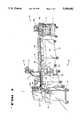
- FIG. 3is a perspective view of a patient table and dual tomographic x-ray generator heads of the x-ray component of the lithotripsy system of the preferred embodiment.
- FIG. 4is a cross-sectional representation of a control unit and a stone breaking unit of the lithotripsy system of the preferred embodiment.
- FIG. 5is a detailed top plan perspective view of an acoustical lens assembly of the lithotripsy system of the preferred embodiment.
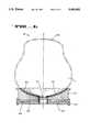
- FIG. 6is a cross-sectional view of the acoustical lens assembly taken as section A--A of FIG. 5.
- FIG. 7is a bottom plan, exploded, perspective view of piezoelectric crystals bonded to the acoustical lens and of coupling copper mesh.
- FIG. 8is a circuit diagram of a piezoelectric crystal triggering circuit as may be utilized by the lithotripsy system of the preferred embodiment.
- FIG. 9is a graphic representation of the timing sequence of the triggering circuit of FIG. 8.
- FIG. 10is a graphic representation of the voltage profile from a crystal of FIG. 8.
- FIG. 1illustrates a perspective overview of the lithotripsy system 100 of the present invention.
- the lithotripsy system 100is comprised of an ultrasound imaging unit 125, a mobile x-ray unit 126 and a lithotripter unit 127.
- the ultrasound imaging unit 125is a self-contained system that can be utilized as a stand alone ultrasound unit, in addition to functioning as a real-time ultrasonic imaging system for the lithotripter 100.
- the ultrasound imaging unit 125is comprised of a control panel 600, a hand-held imaging probe 110, and a monitoring unit 109.
- the x-ray unit 126provides for fluoroscopic image processing and spot film capabilities.
- a urological table 113ais docked to a lithotripter table 113b and locked into place by the docking latch 112.
- the preferred embodimentillustrates the use of docking latch 112
- any means of stably connecting the two tables togetheris within the spirit and scope of the present invention.
- the use of only a single tableis also within the scope of the present invention.
- the urological table 113acan be used as a stand alone examination table for routine urological procedures with or without the use of the x-ray unit 126.
- Table 113ais supported at one end by support 204 and, when docked with table 113b, at the other end by lithotripter unit 127.
- the x-ray unit 126is comprised of mobile C-arm 111, a pair of fluoro exposure monitors 106a and 106b contained within monitor enclosure 106, a control unit 105, and a monitor can 104.
- FIG. 1preferably illustrates a mobile C-arm 111 as a means for providing fluoroscopic images
- a standard x-ray unitis also an acceptable means of providing the necessary fluoroscopic images.
- the mobile C-arm 111, as well as a standard x-ray unitis typically comprised of a tomographic x-ray generator head 101 and a means for receiving fluoroscopic images 102.
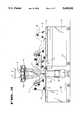
- FIG. 2adescribes the patient P in relationship to the tomographic x-ray generator head 101 and means for receiving fluoroscopic images 102.
- the patient Pis positioned on a planar surface, with the upper portion of the body inclined upward on a headrest 201.
- the lower portion of the bodyis immobilized by placing the patient's knees over a leg rest 202.
- a dual fluoroscopic imageis then obtained by acquiring two oblique images.
- the oblique imagesare obtained by moving the tomographic x-ray generator head 101 off axis by +9 degrees and -9 degrees.
- FIG. 2(b)describes the patient P in relationship to an acoustical lens 205 of the lithotripter unit 127.
- the acoustical lens 205will be described in more detail with reference to FIGS. 5-7.
- the patient Pstill positioned on the planar surface and the headrest 201 and leg rest 202 are moved from one end of a treatment table to the other end of the table.
- An ultrasound probe 206is positioned centrally within the lens 205.
- a focussed shockwave 207is directed at the kidney stone previously located by the dual fluoroscopic images as described in FIG. 2(a). The prelocation procedure is described in more detail below.
- FIG. 2(c)describes the patient P in relationship to an ultrasound imaging probe 206 of the lithotripter unit 127.
- the imaging probe 206is, preferably, centrally located in the acoustical lens 205, allowing for ultrasound localization and real-time monitoring.
- the central location of the imaging probe 206provides a multi-zone focussing array 208 allowing for an extended field-of-view.
- the lithotripsy table 113b docked to the urological treatment table 113a and the x-ray unitis illustrated.
- the two tables 113a and 113bare docked and then latched together for stability providing a platform for a moveable planar surface or a "sled" 107.
- the docking latch 112is dropped into place once the tables are docked together.
- any functionally equivalent latching meansmay be used so long as the latching means provides stability for the tables and allows the use of the sled 107.
- the patient Pis placed on the sled 107.
- the sled 107is located at position 1, which is at the urological table 113a.
- the patient Pmust remain essentially immobile. Immobility is achieved by locking the sled 107 into position and by the careful placement of the patient P.
- the upper portion of the patient's bodyis positioned against a headrest 201, while the patient's legs are placed over the leg rest 202. This allows the patient's back to rest directly and comfortably on the upper surface of the sled 107. In addition to the relative comfort, the patient is made immobile.
- a fluoroscopic exposureis taken of the stone X.
- the precise position of the stone Xis achieved by taking two x-ray views with the tomographic x-ray generator head 101 at a +9 degree oblique setting 101a and a -9 degree oblique setting 101b. After the two oblique views are acquired, the processing unit of the x-ray control unit 105, shown in FIG. 1, calculates the coordinates of the stone X within the body.
- the stone Xis marked on the dual monitors 106 with a marking symbol, such as a cross-hair marker.
- the coordinatesare then calculated with reference to radiopaque markers embedded in the surface of table 113a.
- the patient Pis moved into position 2, via the sled 107, onto the lithotripter housing 103.
- the sled 107is then locked into position.
- the stone coordinates obtained from the x-ray prelocalizationare sent to the lithotripter unit 127 for positioning the stonebreaker focal point.
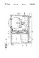
- FIG. 4illustrates the positioning of the acoustical lens 205 and stone-breaking assembly 301 within the lithotripter control housing 103.
- the housing 103is provided with wheels 310, thus increasing the mobility of the lithotripter system 100.
- the wheels 310are not essential to the practice of the present invention.
- a portion of the housing 103is utilized by the several electronic controls units.
- a system controller 307, a pulse modulator 306, a servo amplifier 308 and the servo control unit 309are located within the housing 103. All of the units are typically constructed from well-known prior art circuitry and sequences.
- the servo control unit 309drives the servo amplifier 308, which in turn controls a positioning system 303.
- the control unit 309employs algorithms consisting of prior art sequences typically used to control robotic mechanisms.
- the positioning system 303controls the positioning of the stone-breaking assembly 301 in manner similar to the computer control of a robotic arm.
- the use of robotic algorithms with the positioning system 303virtually eliminates patient handling, since a 5-axis positioning of the acoustical lens 205 is now available.
- the ability to rotate or otherwise position the focussed shock waveadditionally aids in the minimization of pain and the shortening of treatment duration.
- the positioning system 303is able to compensate and rotate to an alternative position, thereby avoiding the rib.
- the housing 103also functions as a base for the lithotripter table 113b.
- An area located directly over a flexible water containment enclosure (waterbag) 302is open, providing for direct patient contact with the water bag 302.
- the patient's backis positioned over the water bag 302, allowing the weight of the patient to force the bag 302 downward causing the waterbag 302 to conform to the shape of the patient's back. This provides necessary coupling between the water bag 302 and the patient so that the shockwaves propagated through the water bag 302 will travel uninhibited to and through the patient's body, ultimately shattering the kidney stone.
- the stone breaking apparatus 301is illustrated.
- the assembly 301is comprised of the acoustical lens 205, a piezoelectric crystal array 405, a coupling means 407, a mechanical standoff 403 and a supporting back plate 404.
- the acoustical lens 205is fabricated in the shape of an ellipsoid.
- the lens 205is shaped from a singular piece of aluminum alloy.
- other materialscould be used that have characteristics that allow the propagation and focussing of energy from piezoelectric crystals and still be within the scope and spirit of the present invention.
- the shape of the lens 205is generally ellipsoid, such that the concave inside surface 408 is defined by the following equation:
- the lens 205 of the preferred embodimentmeasures approximately 18.75 inches from flange to flange with a depth of approximately 3.95 inches from top to bottom.
- a center opening 401allows for placement of an ultrasonic probe approximately 3.31 inches in diameter.
- the stone breaking apparatus 301is provided with an upper flange 402, which allows the lens 205 to be positioned within the apparatus 301 itself.
- the assembly 301is held together with a supporting back plate 404.
- FIG. 6section A--A of FIG. 5 is illustrated.
- the water bag 302is illustrated to show its relationship to the acoustical lens 205.
- the acoustical lens 205is positioned such that the water bag 302 positioned directly on the concave upper surface 408 of the lens 205.
- the back support plate 404holds the stone breaking apparatus 301 together.
- the water bag 302is comprised of two independent bags. There is an inner-bag 1 that is attached by being pinched between the top lens flange 402 and a ring, which is then secured to the lens 205 with screws.
- the outer bag 2is secured to the outside diameter of lens 205 with a hose clamp-line strap. This outer bag 2 serves as a back up seal in case the inner bag 1 should rupture.
- the piezoelectric crystals 405are circularly arranged in an array of approximately 720 square pillars or elements.
- the preferred embodimentpresently uses a C5800 ceramic for the crystals 405.
- any ceramics demonstrating the same or functionally equivalent characteristicsmay be used and still be within the spirit and scope of the present invention.
- the crystals 405are encapsulated. This provides electrical insulation and seals the crystals 405.
- a generic materialsuch as an RTV silicon elastomer is used to encapsulate the crystals 405.
- An acoustical matching layer 410may be placed on the concave surface 408 of the lens 205.
- the matching layer 410may comprise a generic type of epoxy or plastic used to provide a better acoustic impedance match between the lens material and the water. Of necessity, this material is dependent on the lens material.
- the acoustic matching layer 410is illustrated in the preferred embodiment of the present invention, it is not essential to the practice of this invention. However, the epoxy or plastic when used, needs to have similar matching characteristics to the material selected for the lens 205.
- this layerreduces the sharp transition zone at the water/lens interface.
- the piezoelectric crystals 405mounted on the bottom surface of the acoustical lens 205 is described.
- the piezoelectric crystals 405are positioned.
- the crystals 405are positioned in a circular array similar to a mosaic, of approximately 720 square pillars. Each pillar occupies an area of 0.09 square inches. The volume is approximately 0.045 cubic inches.
- a single large crystalmay be shaped to cover the button surface of the lens 205.
- several larger piecesmay be utilized.
- the preferred embodimentprovides 720 pillars to allow for easier replacement of broken pillars.
- the arrangementis preferred since a broken pillar is much easier to replace.
- the mosaic of crystal pillarsdecreases the lateral stress and if any one of the pillars should crack, the crack will not propagate through the entire piezoelectric crystal 405 array.
- the crystals 405are bonded to the bottom surface of the lens 405 using an adhesive available under the trade name of Emerson Cummings 1264 Epoxy.
- the crystals 405are positioned, all the pillars are wired in parallel providing for parallel exitation from a single power supply.
- the parallel wiringis accomplished by placing a voltage coupling means on the bottom of the crystals 405.
- a copper mesh 409is bonded to the top of the crystals 405 using a silver epoxy.
- any voltage coupling means accomplishing the same objectivemay be used and still be within the scope of the present invention.
- FIGS. 8-10illustrate the crystal triggering circuit, the resultant wave form and the timing sequence for the triggering pulse.
- a power supply 501is used to excite the piezoelectric crystal 508.
- the power supply 501 of the preferred embodimentis a Phazon model PM3020A.
- the power supply 501is coupled to a hydrogen spark gap tube 503, the inductor 504 and the piezoelectric crystal 508.
- the pulse generating circuit for the spark gap robe 503is described in FIG. 9.
- a Phazon model PM3020Ais used in the preferred embodiment, any power supply or ramp source having similar characteristics would be acceptable for use with the present invention.
- the power supply 501provides a constant current source manually adjustable from 1 to approximately 60 milliamps.
- the power supplyprovides an output voltage range of to 160 VDC in approximately 128 equal steps with a tolerance of a +/-3% of setting.
- the output currentis adjustable within the range of 0-25 milliamps.
- the currentmust and is stable within a +/-3% of the set current. Transient response is less than 2 milliseconds.
- the power supplyprovides for an input line frequency of 47-67 hertz.
- the supply 501comprises an under voltage protection.
- the initial trigger pulsecomes from the controller panel 600 of the lithotripter system 100.
- the trigger pulsecontrols the ramp output of the power supply 501.
- the power supply 501receives the trigger pulse, the power supply turns on and ramps up to a predetermined voltage.
- the voltage across the capacitive loadwhich in this case is the crystal 508, follows a similar ramp profile.
- the spark gap tube 503encounters a similar ramp voltage.
- the spark gap tube 503triggers, creating a short circuit between the spark gap tube 503, an inductor 504 and the crystal 508.
- a delayed reset pulseis sent to terminal 502. This allows the spark gap tube 503 to be reopened following the discharge of the stored current into the crystal 508. This permits a second pulse or any additional pulses with minimal time delay.
- FIG. 9illustrates a timing diagram of the pulse sequences used for triggering the spark gap tube 503 and the piezoelectric crystal 508.
- Pulse sequence Aillustrates the initial triggering pulse from the controller 600.
- Sequence Billustrates the ramp up of the power supply 501.
- Sequence Cillustrates the corresponding ramp up of the spark gap tube 503.
- Sequence Dshows the generation of the time delay initiated by the firing of the spark gap tube 503. Following this time delay, a reset pulse is sent to the spark gap tube 503 via terminal 502.
- FIG. 10illustrates corresponding voltage ramp across the crystal 503 as the power supply ramps.
- a crystalabsorbs the voltage, flexing continuously until the spark gap tube 503 triggers. Once the tube 502 is triggered, the output voltage across the capacitive load of the crystal 508 is rapidly discharged through inductor 504. The reduction of the voltage on the crystal 508 from its peak 510 to its relaxed state 511 should be essentially instantaneous.
- An advantage of the pulsing circuit of FIG. 8is that due to the relatively slow ramp time of the power supply and the crystal 508 there is minimal stress applied to the crystal 508 until just prior to triggering.
- the slow, continuous rampprovides for a continuous rate of "deformation" of the crystal 508. This is opposed to a rapid deformation of the crystal 508 which could result in premature triggering. Furthermore, when the voltage across the crystal 508 is removed, the theoretical circuitry should affect an instantaneous return to the normal relaxed state of the crystal. To effect a rapid discharge of the crystal voltage, inductor 504 is chosen to produce a critically damp circuit, with the resistance of such a circuit being the intrinsic resistance of the crystal 508. In the preferred embodiment, the inductor 504 is approximately one microhenry. Once the voltage is removed from the crystal 508, this instantaneous return to the normal state produces a disruptive or sonic wave front. This wave front is propogated through the acoustical lens 205 focussing to a narrow focal point coincident with the kidney stone, thus providing the necessary energy to shatter the kidney stone.
- the shockwave generation systemis cost effective, producing a narrow cross-sectional focussed shockwave, with a minimal amount of pain but with a maximum amount of energy efficiency.
Landscapes
- Health & Medical Sciences (AREA)
- Life Sciences & Earth Sciences (AREA)
- Engineering & Computer Science (AREA)
- Medical Informatics (AREA)
- Nuclear Medicine, Radiotherapy & Molecular Imaging (AREA)
- Surgery (AREA)
- Animal Behavior & Ethology (AREA)
- Veterinary Medicine (AREA)
- Biomedical Technology (AREA)
- Heart & Thoracic Surgery (AREA)
- Radiology & Medical Imaging (AREA)
- Molecular Biology (AREA)
- Public Health (AREA)
- General Health & Medical Sciences (AREA)
- Vascular Medicine (AREA)
- Orthopedic Medicine & Surgery (AREA)
- Human Computer Interaction (AREA)
- Physics & Mathematics (AREA)
- Biophysics (AREA)
- High Energy & Nuclear Physics (AREA)
- Optics & Photonics (AREA)
- Pathology (AREA)
- Surgical Instruments (AREA)
Abstract
Description
y=13.525-(182.931-1.060x.sup.2).sup.1/2
Claims (10)
Priority Applications (1)
| Application Number | Priority Date | Filing Date | Title |
|---|---|---|---|
| US08/192,063US5409002A (en) | 1989-07-12 | 1994-02-04 | Treatment system with localization |
Applications Claiming Priority (4)
| Application Number | Priority Date | Filing Date | Title |
|---|---|---|---|
| US07/379,568US5065761A (en) | 1989-07-12 | 1989-07-12 | Lithotripsy system |
| US75095691A | 1991-08-28 | 1991-08-28 | |
| US94078092A | 1992-09-04 | 1992-09-04 | |
| US08/192,063US5409002A (en) | 1989-07-12 | 1994-02-04 | Treatment system with localization |
Related Parent Applications (1)
| Application Number | Title | Priority Date | Filing Date |
|---|---|---|---|
| US94078092AContinuation | 1989-07-12 | 1992-09-04 |
Publications (1)
| Publication Number | Publication Date |
|---|---|
| US5409002Atrue US5409002A (en) | 1995-04-25 |
Family
ID=23497782
Family Applications (2)
| Application Number | Title | Priority Date | Filing Date |
|---|---|---|---|
| US07/379,568Expired - Fee RelatedUS5065761A (en) | 1989-07-12 | 1989-07-12 | Lithotripsy system |
| US08/192,063Expired - Fee RelatedUS5409002A (en) | 1989-07-12 | 1994-02-04 | Treatment system with localization |
Family Applications Before (1)
| Application Number | Title | Priority Date | Filing Date |
|---|---|---|---|
| US07/379,568Expired - Fee RelatedUS5065761A (en) | 1989-07-12 | 1989-07-12 | Lithotripsy system |
Country Status (1)
| Country | Link |
|---|---|
| US (2) | US5065761A (en) |
Cited By (79)
| Publication number | Priority date | Publication date | Assignee | Title |
|---|---|---|---|---|
| US5836898A (en)* | 1994-12-07 | 1998-11-17 | U.S. Philips Corporation | Lithotripsy combination comprising a therapy unit |
| US6007243A (en)* | 1996-02-21 | 1999-12-28 | Lunar Corporation | Combined mobile x-ray imaging system and monitor cart |
| US6156549A (en)* | 1997-06-04 | 2000-12-05 | William Drewes | Method of destroying cells via resonant destruction of intracellular structures |
| US6361531B1 (en) | 2000-01-21 | 2002-03-26 | Medtronic Xomed, Inc. | Focused ultrasound ablation devices having malleable handle shafts and methods of using the same |
| US6409720B1 (en) | 2000-01-19 | 2002-06-25 | Medtronic Xomed, Inc. | Methods of tongue reduction using high intensity focused ultrasound to form an ablated tissue area containing a plurality of lesions |
| US6413254B1 (en) | 2000-01-19 | 2002-07-02 | Medtronic Xomed, Inc. | Method of tongue reduction by thermal ablation using high intensity focused ultrasound |
| US20030013970A1 (en)* | 2001-05-29 | 2003-01-16 | Makin Inder Raj. S. | Deployable ultrasound medical transducers |
| US6585731B1 (en)* | 1998-02-20 | 2003-07-01 | Siemens Aktiengesellschaft | Medical-technical system workstation |
| US6595934B1 (en) | 2000-01-19 | 2003-07-22 | Medtronic Xomed, Inc. | Methods of skin rejuvenation using high intensity focused ultrasound to form an ablated tissue area containing a plurality of lesions |
| US20030191396A1 (en)* | 2003-03-10 | 2003-10-09 | Sanghvi Narendra T | Tissue treatment method and apparatus |
| US6654638B1 (en) | 2000-04-06 | 2003-11-25 | Cardiac Pacemakers, Inc. | Ultrasonically activated electrodes |
| US6685639B1 (en)* | 1998-01-25 | 2004-02-03 | Chongqing Hifu | High intensity focused ultrasound system for scanning and curing tumor |
| US6692450B1 (en) | 2000-01-19 | 2004-02-17 | Medtronic Xomed, Inc. | Focused ultrasound ablation devices having selectively actuatable ultrasound emitting elements and methods of using the same |
| US20040059319A1 (en)* | 2002-07-26 | 2004-03-25 | Dornier Medtech Systems Gmbh | System and method for a lithotripter |
| EP1123640A4 (en)* | 1998-10-19 | 2004-05-06 | Fluoroscan Imaging Systems Inc | Miniature c-arm apparatus with dual monitor system and single driver interface therefor |
| US20040106870A1 (en)* | 2001-05-29 | 2004-06-03 | Mast T. Douglas | Method for monitoring of medical treatment using pulse-echo ultrasound |
| US20040127791A1 (en)* | 2001-05-29 | 2004-07-01 | Mast T. Douglas | Method for mapping temperature rise using pulse-echo ultrasound |
| US20040167397A1 (en)* | 2003-02-25 | 2004-08-26 | Hmt Holding Ag | Medical system |
| US20050010140A1 (en)* | 2001-11-29 | 2005-01-13 | Dornier Medtech Systems Gmbh | Shockwave or pressure-wave type therapeutic apparatus |
| US20050053198A1 (en)* | 2003-01-23 | 2005-03-10 | Dornier Medtech Systems Gmbh | Urological working place |
| AU2003200533B2 (en)* | 1998-01-25 | 2005-04-07 | Chongqing Haifu Medical Technology Co., Ltd. | A High Intensity Focused Ultrasound System for Scanning and Curing Tumors |
| US20050173165A1 (en)* | 2003-02-07 | 2005-08-11 | Dornier Medtech Systems Gmbh | Lithotriptor carriage |
| US20050228286A1 (en)* | 2004-04-07 | 2005-10-13 | Messerly Jeffrey D | Medical system having a rotatable ultrasound source and a piercing tip |
| US20050234438A1 (en)* | 2004-04-15 | 2005-10-20 | Mast T D | Ultrasound medical treatment system and method |
| US20050240124A1 (en)* | 2004-04-15 | 2005-10-27 | Mast T D | Ultrasound medical treatment system and method |
| US20050240125A1 (en)* | 2004-04-16 | 2005-10-27 | Makin Inder Raj S | Medical system having multiple ultrasound transducers or an ultrasound transducer and an RF electrode |
| US20050240127A1 (en)* | 2004-03-02 | 2005-10-27 | Ralf Seip | Ultrasound phased arrays |
| US20050240105A1 (en)* | 2004-04-14 | 2005-10-27 | Mast T D | Method for reducing electronic artifacts in ultrasound imaging |
| US20050256405A1 (en)* | 2004-05-17 | 2005-11-17 | Makin Inder Raj S | Ultrasound-based procedure for uterine medical treatment |
| US20050261588A1 (en)* | 2004-05-21 | 2005-11-24 | Makin Inder Raj S | Ultrasound medical system |
| US20050261587A1 (en)* | 2004-05-20 | 2005-11-24 | Makin Inder R S | Ultrasound medical system and method |
| US20050261585A1 (en)* | 2004-05-20 | 2005-11-24 | Makin Inder Raj S | Ultrasound medical system |
| US20050261611A1 (en)* | 2004-05-21 | 2005-11-24 | Makin Inder Raj S | Ultrasound medical system and method |
| US20050261586A1 (en)* | 2004-05-18 | 2005-11-24 | Makin Inder R S | Medical system having an ultrasound source and an acoustic coupling medium |
| US20050277853A1 (en)* | 2004-06-14 | 2005-12-15 | Mast T D | System and method for medical treatment using ultrasound |
| US20060089626A1 (en)* | 2004-10-22 | 2006-04-27 | Vlegele James W | Surgical device guide for use with an imaging system |
| US20060089624A1 (en)* | 2004-10-22 | 2006-04-27 | Voegele James W | System and method for planning treatment of tissue |
| US20060089625A1 (en)* | 2004-10-22 | 2006-04-27 | Voegele James W | System and method for treatment of tissue using the tissue as a fiducial |
| US20060260804A1 (en)* | 2005-05-17 | 2006-11-23 | O'malley Edward J | Surface activated downhole spark-gap tool |
| US20070010805A1 (en)* | 2005-07-08 | 2007-01-11 | Fedewa Russell J | Method and apparatus for the treatment of tissue |
| US20070016184A1 (en)* | 2005-07-14 | 2007-01-18 | Ethicon Endo-Surgery, Inc. | Medical-treatment electrode assembly and method for medical treatment |
| US20070016112A1 (en)* | 2005-06-09 | 2007-01-18 | Reiner Schultheiss | Shock Wave Treatment Device and Method of Use |
| US20070038096A1 (en)* | 2005-07-06 | 2007-02-15 | Ralf Seip | Method of optimizing an ultrasound transducer |
| US20070055157A1 (en)* | 2005-08-05 | 2007-03-08 | Dornier Medtech Systems Gmbh | Shock wave therapy device with image production |
| US20070219448A1 (en)* | 2004-05-06 | 2007-09-20 | Focus Surgery, Inc. | Method and Apparatus for Selective Treatment of Tissue |
| US20080039724A1 (en)* | 2006-08-10 | 2008-02-14 | Ralf Seip | Ultrasound transducer with improved imaging |
| US20080077056A1 (en)* | 2006-09-21 | 2008-03-27 | Shuhei Kagosaki | HIFU probe for treating tissue with in-line degassing of fluid |
| US20080267927A1 (en)* | 2004-12-15 | 2008-10-30 | Dornier Medtech Systems Gmbh | Methods for improving cell therapy and tissue regeneration in patients with cardiovascular diseases by means of shockwaves |
| US20080319356A1 (en)* | 2005-09-22 | 2008-12-25 | Cain Charles A | Pulsed cavitational ultrasound therapy |
| US7485101B1 (en)* | 2002-03-22 | 2009-02-03 | Faragalla Yousry B | Multiple shockwave focal treatment apparatus with targeting positioning and locating apparatus |
| US20090069677A1 (en)* | 2007-09-11 | 2009-03-12 | Focus Surgery, Inc. | System and method for tissue change monitoring during hifu treatment |
| US20090173492A1 (en)* | 2005-05-17 | 2009-07-09 | Baker Hughes Incorporated | Surface activated downhole spark-gap tool |
| US20090275866A1 (en)* | 2008-05-02 | 2009-11-05 | Daniel Gelbart | Lithotripsy system with automatic 3D tracking |
| US20100069797A1 (en)* | 2005-09-22 | 2010-03-18 | Cain Charles A | Pulsed cavitational ultrasound therapy |
| CN1572270B (en)* | 2003-05-30 | 2010-05-26 | 西门子公司 | Device for holding at least one ultrasound probe |
| US20100286574A1 (en)* | 2006-01-17 | 2010-11-11 | Dornier Medtech Systems Gmbh | Treating apparatus |
| US20110040190A1 (en)* | 2009-08-17 | 2011-02-17 | Jahnke Russell C | Disposable Acoustic Coupling Medium Container |
| US20110054363A1 (en)* | 2009-08-26 | 2011-03-03 | Cain Charles A | Devices and methods for using controlled bubble cloud cavitation in fractionating urinary stones |
| US20110201976A1 (en)* | 2005-06-01 | 2011-08-18 | Focus Surgery, Inc. | Laparoscopic hifu probe |
| US8539813B2 (en) | 2009-09-22 | 2013-09-24 | The Regents Of The University Of Michigan | Gel phantoms for testing cavitational ultrasound (histotripsy) transducers |
| US8852103B2 (en) | 2011-10-17 | 2014-10-07 | Butterfly Network, Inc. | Transmissive imaging and related apparatus and methods |
| US9049783B2 (en) | 2012-04-13 | 2015-06-02 | Histosonics, Inc. | Systems and methods for obtaining large creepage isolation on printed circuit boards |
| US9144694B2 (en) | 2011-08-10 | 2015-09-29 | The Regents Of The University Of Michigan | Lesion generation through bone using histotripsy therapy without aberration correction |
| CN106388903A (en)* | 2016-11-16 | 2017-02-15 | 付现敏 | Intelligent urological extracorporeal lithotripsy system |
| US9636133B2 (en) | 2012-04-30 | 2017-05-02 | The Regents Of The University Of Michigan | Method of manufacturing an ultrasound system |
| US9667889B2 (en) | 2013-04-03 | 2017-05-30 | Butterfly Network, Inc. | Portable electronic devices with integrated imaging capabilities |
| US9943708B2 (en) | 2009-08-26 | 2018-04-17 | Histosonics, Inc. | Automated control of micromanipulator arm for histotripsy prostate therapy while imaging via ultrasound transducers in real time |
| US10219815B2 (en) | 2005-09-22 | 2019-03-05 | The Regents Of The University Of Michigan | Histotripsy for thrombolysis |
| US10293187B2 (en) | 2013-07-03 | 2019-05-21 | Histosonics, Inc. | Histotripsy excitation sequences optimized for bubble cloud formation using shock scattering |
| US10335280B2 (en) | 2000-01-19 | 2019-07-02 | Medtronic, Inc. | Method for ablating target tissue of a patient |
| US10780298B2 (en) | 2013-08-22 | 2020-09-22 | The Regents Of The University Of Michigan | Histotripsy using very short monopolar ultrasound pulses |
| US10820919B2 (en) | 2017-01-06 | 2020-11-03 | Translational Technologies, LLC | Extracorporeal shockwave lithotripsy (ESWL) system and method using in-situ sensing of system and device data and therapeutic/system/device level control |
| US11058399B2 (en) | 2012-10-05 | 2021-07-13 | The Regents Of The University Of Michigan | Bubble-induced color doppler feedback during histotripsy |
| US11135454B2 (en) | 2015-06-24 | 2021-10-05 | The Regents Of The University Of Michigan | Histotripsy therapy systems and methods for the treatment of brain tissue |
| US11432900B2 (en) | 2013-07-03 | 2022-09-06 | Histosonics, Inc. | Articulating arm limiter for cavitational ultrasound therapy system |
| US11648424B2 (en) | 2018-11-28 | 2023-05-16 | Histosonics Inc. | Histotripsy systems and methods |
| US11813485B2 (en) | 2020-01-28 | 2023-11-14 | The Regents Of The University Of Michigan | Systems and methods for histotripsy immunosensitization |
| US12318636B2 (en) | 2022-10-28 | 2025-06-03 | Histosonics, Inc. | Histotripsy systems and methods |
| US12343568B2 (en) | 2020-08-27 | 2025-07-01 | The Regents Of The University Of Michigan | Ultrasound transducer with transmit-receive capability for histotripsy |
Families Citing this family (65)
| Publication number | Priority date | Publication date | Assignee | Title |
|---|---|---|---|---|
| US5230329A (en)* | 1988-11-16 | 1993-07-27 | Medas S.P.A. | Lithotripter with two localization devices in an isocentric system |
| US5065761A (en)* | 1989-07-12 | 1991-11-19 | Diasonics, Inc. | Lithotripsy system |
| US5232853A (en)* | 1989-12-28 | 1993-08-03 | Takeda Chemical Industries, Ltd. | Method for producing (2r,3s)-3-hydroxy-2-methylbutyrate by microbial reduction |
| JP3144849B2 (en)* | 1991-09-30 | 2001-03-12 | 株式会社東芝 | Cardiovascular diagnostic device |
| DE4143540C2 (en)* | 1991-10-24 | 1996-08-08 | Siemens Ag | Therapeutic assembly for treatment by acoustic irradiation |
| US6023165A (en) | 1992-09-28 | 2000-02-08 | Fonar Corporation | Nuclear magnetic resonance apparatus and methods of use and facilities for incorporating the same |
| US5647361A (en)* | 1992-09-28 | 1997-07-15 | Fonar Corporation | Magnetic resonance imaging method and apparatus for guiding invasive therapy |
| US6414490B1 (en) | 1992-12-18 | 2002-07-02 | Fonar Corporation | MRI magnet with enhanced patient entry and positioning |
| US6456075B1 (en) | 1992-12-18 | 2002-09-24 | Fornar Corporation | MRI magnet with enhanced patient entry and positioning |
| US6335623B1 (en) | 1992-12-18 | 2002-01-01 | Fonar Corporation | MRI apparatus |
| US6165139A (en)* | 1993-03-01 | 2000-12-26 | Fonar Corporation | Remotely steerable guide wire with external control wires |
| DE4306459C1 (en)* | 1993-03-02 | 1994-04-28 | Siemens Ag | Ultrasound therapy device using X-ray imaging - uses mounting allowing X-ray imaging from two different directions, with corresponding adjustment of acoustic wave focus |
| JP2878168B2 (en)* | 1995-12-11 | 1999-04-05 | アロカ株式会社 | Bone evaluation device |
| US6752812B1 (en) | 1997-05-15 | 2004-06-22 | Regent Of The University Of Minnesota | Remote actuation of trajectory guide |
| US6267769B1 (en) | 1997-05-15 | 2001-07-31 | Regents Of The Universitiy Of Minnesota | Trajectory guide method and apparatus for use in magnetic resonance and computerized tomographic scanners |
| US7127802B1 (en) | 1997-11-21 | 2006-10-31 | Fonar Corporation | Method of fabricating a composite plate |
| US6185865B1 (en) | 1998-01-26 | 2001-02-13 | University Of Iowa Research Foundation | Method for clearing of fungal spores from seed by ultrasound |
| US6195577B1 (en) | 1998-10-08 | 2001-02-27 | Regents Of The University Of Minnesota | Method and apparatus for positioning a device in a body |
| US6195936B1 (en) | 1999-02-22 | 2001-03-06 | University Of Iowa Research Foundation | Method for uptake of a substance into a seed |
| FR2799109A1 (en)* | 1999-10-01 | 2001-04-06 | Internova Int Innovation | Internal anatomical anomaly location system scans X-ray source to give triangulation for shock wave treatment |
| US6828792B1 (en) | 1999-11-24 | 2004-12-07 | Fonar Corporation | MRI apparatus and method for imaging |
| US6677753B1 (en) | 1999-11-24 | 2004-01-13 | Fonar Corporation | Stand-up MRI apparatus |
| US7366561B2 (en) | 2000-04-07 | 2008-04-29 | Medtronic, Inc. | Robotic trajectory guide |
| US7660621B2 (en) | 2000-04-07 | 2010-02-09 | Medtronic, Inc. | Medical device introducer |
| US8190234B2 (en) | 2000-07-28 | 2012-05-29 | Fonar Corporation | Movable patient support with spatial locating feature |
| US7697971B1 (en) | 2000-07-28 | 2010-04-13 | Fonar Corporation | Positioning system for an MRI |
| US7196519B2 (en)* | 2000-07-28 | 2007-03-27 | Fonar Corporation | Stand-up vertical field MRI apparatus |
| AU2001285071A1 (en) | 2000-08-17 | 2002-02-25 | John David | Trajectory guide with instrument immobilizer |
| US6453609B1 (en) | 2000-09-06 | 2002-09-24 | University Of Iowa Research Foundation | Method for uptake of a substance into a seed |
| US6934574B1 (en) | 2001-06-21 | 2005-08-23 | Fonar Corporation | MRI scanner and method for modular patient handling |
| US6944492B1 (en) | 2001-10-01 | 2005-09-13 | Fonar Corporation | Patient bed support for an open MRI system |
| US7906966B1 (en) | 2001-10-05 | 2011-03-15 | Fonar Corporation | Quadrature foot coil antenna for magnetic resonance imaging |
| US7701209B1 (en) | 2001-10-05 | 2010-04-20 | Fonar Corporation | Coils for horizontal field magnetic resonance imaging |
| US7327863B1 (en) | 2001-11-21 | 2008-02-05 | Fonar Corporation | Stand-up patient handling system control kiosk and controller |
| US6695834B2 (en) | 2002-01-25 | 2004-02-24 | Scimed Life Systems, Inc. | Apparatus and method for stone removal from a body |
| US6866651B2 (en) | 2002-03-20 | 2005-03-15 | Corazon Technologies, Inc. | Methods and devices for the in situ dissolution of renal calculi |
| US7123008B1 (en) | 2002-04-19 | 2006-10-17 | Fonar Corporation | Positional magnetic resonance imaging |
| US8036730B1 (en) | 2002-04-19 | 2011-10-11 | Fonar Corporation | Temporal magnetic resonance imaging |
| US7551954B2 (en)* | 2002-04-25 | 2009-06-23 | Fonar Corporation | Magnetic resonance imaging with adjustable fixture apparatus |
| US7704260B2 (en) | 2002-09-17 | 2010-04-27 | Medtronic, Inc. | Low profile instrument immobilizer |
| US7102353B1 (en) | 2002-11-29 | 2006-09-05 | Fonar Corporation | Magnetic resonance imaging apparatus having moving magnets |
| US7636596B2 (en) | 2002-12-20 | 2009-12-22 | Medtronic, Inc. | Organ access device and method |
| US7275796B2 (en)* | 2003-02-13 | 2007-10-02 | Bochner Ronnie Z | Device for facilitating medical examination |
| US7896889B2 (en) | 2003-02-20 | 2011-03-01 | Medtronic, Inc. | Trajectory guide with angled or patterned lumens or height adjustment |
| US8064984B2 (en) | 2003-03-18 | 2011-11-22 | Esaote S.P.A. | Magnetic resonance imaging apparatus |
| EP1493389A1 (en)* | 2003-07-01 | 2005-01-05 | Siemens Aktiengesellschaft | Method of and device for forming x-ray images of the focal region of a lithotripter |
| US7030612B1 (en) | 2004-01-13 | 2006-04-18 | Fonar Corporation | Body rest for magnetic resonance imaging |
| US20050182420A1 (en) | 2004-02-13 | 2005-08-18 | Schulte Gregory T. | Low profile apparatus for securing a therapy delivery device within a burr hole |
| US8401615B1 (en) | 2004-11-12 | 2013-03-19 | Fonar Corporation | Planar coil flexion fixture for magnetic resonance imaging and use thereof |
| EP1827221A4 (en)* | 2004-11-24 | 2009-08-26 | Fonar Corp | Immobilization fixture for magnetic resonance imaging |
| US7497863B2 (en) | 2004-12-04 | 2009-03-03 | Medtronic, Inc. | Instrument guiding stage apparatus and method for using same |
| US7744606B2 (en) | 2004-12-04 | 2010-06-29 | Medtronic, Inc. | Multi-lumen instrument guide |
| DE102005031118A1 (en)* | 2005-07-04 | 2007-01-11 | Siemens Ag | Method for aligning the focal point of an ultrasonic impact wave with a target in a patient e.g. for pain therapy or stone removal |
| US8401612B1 (en) | 2006-09-11 | 2013-03-19 | Fonar Corporation | Magnetic resonance imaging system and method for detecting chiari malformations |
| US8535250B2 (en)* | 2006-10-13 | 2013-09-17 | University Of Washington Through Its Center For Commercialization | Method and apparatus to detect the fragmentation of kidney stones by measuring acoustic scatter |
| US9386939B1 (en) | 2007-05-10 | 2016-07-12 | Fonar Corporation | Magnetic resonance imaging of the spine to detect scoliosis |
| US8599215B1 (en) | 2008-05-07 | 2013-12-03 | Fonar Corporation | Method, apparatus and system for joining image volume data |
| EP2753250B1 (en) | 2011-09-10 | 2019-03-20 | Cook Medical Technologies LLC | Control handles for medical devices |
| US10349958B2 (en) | 2012-03-27 | 2019-07-16 | Cook Medical Technologies Llc | Lithotripsy probes and methods for performing lithotripsy |
| US9766310B1 (en) | 2013-03-13 | 2017-09-19 | Fonar Corporation | Method and apparatus for magnetic resonance imaging of the cranio-cervical junction |
| US9360124B2 (en) | 2013-03-15 | 2016-06-07 | Cook Medical Technologies Llc | Bi-directional valve device for selective control of fluid flow through multiple converging paths |
| US10350439B2 (en)* | 2013-03-28 | 2019-07-16 | University Of Washington Through Its Center For Commercialization | Focused ultrasound apparatus and methods of use |
| KR102211335B1 (en) | 2013-12-20 | 2021-02-03 | 마이크로벤션, 인코포레이티드 | Device delivery system |
| US9517512B2 (en)* | 2014-09-26 | 2016-12-13 | Chuan Liang Industrial Co., Ltd. | Ultrasonic positioning device for five-axis machine |
| US10252035B2 (en) | 2015-12-07 | 2019-04-09 | Cook Medical Techonologies Llc | Rotatable control handles for medical devices and methods of using rotatable control handles |
Citations (54)
| Publication number | Priority date | Publication date | Assignee | Title |
|---|---|---|---|---|
| US2467301A (en)* | 1945-07-23 | 1949-04-12 | Sperry Prod Inc | Supersonic inspection for flaws lying near the surface of apart |
| US2488290A (en)* | 1946-11-26 | 1949-11-15 | Gen Electric | Piezoelectric crystal holder |
| US2559227A (en)* | 1947-05-24 | 1951-07-03 | Interval Instr Inc | Shock wave generator |
| US3117571A (en)* | 1957-02-28 | 1964-01-14 | Univ Illinois | Production of reversible changes in living tissue by ultrasound |
| US3129366A (en)* | 1960-12-19 | 1964-04-14 | Westinghouse Electric Corp | Power supply for an electro-mechanical vibrating transducer |
| US3237623A (en)* | 1963-02-04 | 1966-03-01 | George A D Gordon | Apparatus for destroying limited groups of cells |
| US3735755A (en)* | 1971-06-28 | 1973-05-29 | Interscience Research Inst | Noninvasive surgery method and apparatus |
| US3756071A (en)* | 1969-06-06 | 1973-09-04 | Realisations Ultrasoniques Sa | Process and apparatus for analyzing materials by means of ultrasonic pulses, employing the transfer function characteristic of each obstacle |
| US3942531A (en)* | 1973-10-12 | 1976-03-09 | Dornier System Gmbh | Apparatus for breaking-up, without contact, concrements present in the body of a living being |
| US3958559A (en)* | 1974-10-16 | 1976-05-25 | New York Institute Of Technology | Ultrasonic transducer |
| US4005258A (en)* | 1973-11-26 | 1977-01-25 | Realization Ultrasoniques | Ultrasonic examination |
| US4187556A (en)* | 1960-04-05 | 1980-02-05 | The United States Of America As Represented By The Secretary Of The Navy | Electro-acoustic transducer with line focus |
| US4281661A (en)* | 1977-11-23 | 1981-08-04 | C. G. R.-Ultrasonic | Medical echo sounding apparatus with a wide sector scanning angle |
| US4311147A (en)* | 1979-05-26 | 1982-01-19 | Richard Wolf Gmbh | Apparatus for contact-free disintegration of kidney stones or other calculi |
| US4315514A (en)* | 1980-05-08 | 1982-02-16 | William Drewes | Method and apparatus for selective cell destruction |
| US4340944A (en)* | 1980-03-07 | 1982-07-20 | Cgr Ultrasonic | Ultrasonic echographic probe having an acoustic lens and an echograph incorporating said probe |
| US4376255A (en)* | 1980-03-14 | 1983-03-08 | Siemens Aktiengesellschaft | Method for pulse triggering of a piezo-electric sound-transmitting transducer |
| EP0018614B1 (en)* | 1979-05-01 | 1983-03-30 | Toray Industries, Inc. | An improved electro-acoustic transducer element |
| DE3142639A1 (en)* | 1981-10-28 | 1983-05-05 | Battelle-Institut E.V., 6000 Frankfurt | Device for radiating and for receiving focused ultrasonic waves |
| US4386530A (en)* | 1980-01-21 | 1983-06-07 | Hitachi, Ltd. | Ultrasonic imaging equipment |
| US4391281A (en)* | 1977-01-06 | 1983-07-05 | Sri International | Ultrasonic transducer system and method |
| GB2113099A (en)* | 1982-01-07 | 1983-08-03 | Technicare Corp | Apparatus for imaging and thermally treating tissue using ultrasound |
| US4418698A (en)* | 1980-07-29 | 1983-12-06 | Jacques Dory | Ultrasonic scanning probe with mechanical sector scanning means |
| US4472975A (en)* | 1982-01-11 | 1984-09-25 | Tac Technical Instrument Corporation | Ultrasonic transducer coupler for flaw detection systems |
| US4474180A (en)* | 1982-05-13 | 1984-10-02 | The United States Of America As Represented By The Administrator Of The National Aeronautics And Space Administration | Apparatus for disintegrating kidney stones |
| US4484569A (en)* | 1981-03-13 | 1984-11-27 | Riverside Research Institute | Ultrasonic diagnostic and therapeutic transducer assembly and method for using |
| US4486680A (en)* | 1982-03-04 | 1984-12-04 | Richard Wolf Gmbh | Ultrasonic piezoelectric disintegrater |
| US4495817A (en)* | 1982-05-26 | 1985-01-29 | The Ontario Cancer Institute | Ultrasonic imaging device |
| US4526168A (en)* | 1981-05-14 | 1985-07-02 | Siemens Aktiengesellschaft | Apparatus for destroying calculi in body cavities |
| US4539989A (en)* | 1981-11-25 | 1985-09-10 | Dornier System Gmbh | Injury-free coupling and decoupling of therapeutic shock waves |
| US4570634A (en)* | 1982-11-06 | 1986-02-18 | Dornier System Gmbh | Shockwave reflector |
| US4617931A (en)* | 1983-12-14 | 1986-10-21 | Jacques Dory | Ultrasonic pulse apparatus for destroying calculuses |
| US4618796A (en)* | 1984-10-12 | 1986-10-21 | Richard Wolf Gmbh | Acoustic diode |
| US4622969A (en)* | 1983-06-10 | 1986-11-18 | Dornier System Gmbh | Shock wave matching in therapeutic equipment |
| US4646756A (en)* | 1982-10-26 | 1987-03-03 | The University Of Aberdeen | Ultra sound hyperthermia device |
| US4655205A (en)* | 1984-05-12 | 1987-04-07 | Dornier System Gmbh | Delineating and limiting the zone of shock waves for therapeutic purposes |
| US4658828A (en)* | 1984-05-03 | 1987-04-21 | Jacques Dory | Apparatus for examining and localizing tumors using ultra sounds, comprising a device for localized hyperthermia treatment |
| US4664111A (en)* | 1985-01-21 | 1987-05-12 | Siemens Aktiengesellschaft | Apparatus for producing time-staggered shock waves |
| US4669483A (en)* | 1984-07-21 | 1987-06-02 | Dornier System Gmbh | Lithotripsy system having locating and orienting apparatus |
| US4669472A (en)* | 1984-11-28 | 1987-06-02 | Wolfgang Eisenmenger | Contactless comminution of concrements in the body of a living being |
| US4674505A (en)* | 1983-08-03 | 1987-06-23 | Siemens Aktiengesellschaft | Apparatus for the contact-free disintegration of calculi |
| US4718421A (en)* | 1985-08-09 | 1988-01-12 | Siemens Aktiengesellschaft | Ultrasound generator |
| US4721106A (en)* | 1984-07-14 | 1988-01-26 | Richard Wolf Gmbh | Piezoelectric transducer for destruction of concretions inside the body |
| US4721108A (en)* | 1982-11-04 | 1988-01-26 | Dornier System Gmbh | Generator for a pulse train of shockwaves |
| US4749897A (en)* | 1986-03-12 | 1988-06-07 | Nippondenso Co., Ltd. | Driving device for piezoelectric element |
| EP0280088A1 (en)* | 1987-02-16 | 1988-08-31 | Siemens Aktiengesellschaft | Sound generator for treating a living being with focused sound waves |
| US4803995A (en)* | 1986-06-27 | 1989-02-14 | Kabushiki Kaisha Toshiba | Ultrasonic lithotrity apparatus |
| US4821730A (en)* | 1985-12-12 | 1989-04-18 | Richard Wolf Gmbh | Ultrasonic scanner and shock wave generator |
| US4860331A (en)* | 1988-09-12 | 1989-08-22 | Williams John F | Image marker device |
| US4858597A (en)* | 1983-06-01 | 1989-08-22 | Richard Wolf Gmbh | Piezoelectric transducer for the destruction of concretions within an animal body |
| US4869239A (en)* | 1985-09-13 | 1989-09-26 | Richard Wolf Gmbh | Device for locating and disintegrating concretions in bodily cavities |
| US4936291A (en)* | 1984-07-18 | 1990-06-26 | Dornier System Gmbh | Concrement locating apparatus utilizing X-rays and ultrasonic detectors |
| US4962754A (en)* | 1988-01-13 | 1990-10-16 | Kabushiki Kaisha Toshiba | Shock wave treatment apparatus |
| US5065761A (en)* | 1989-07-12 | 1991-11-19 | Diasonics, Inc. | Lithotripsy system |
- 1989
- 1989-07-12USUS07/379,568patent/US5065761A/ennot_activeExpired - Fee Related
- 1994
- 1994-02-04USUS08/192,063patent/US5409002A/ennot_activeExpired - Fee Related
Patent Citations (55)
| Publication number | Priority date | Publication date | Assignee | Title |
|---|---|---|---|---|
| US2467301A (en)* | 1945-07-23 | 1949-04-12 | Sperry Prod Inc | Supersonic inspection for flaws lying near the surface of apart |
| US2488290A (en)* | 1946-11-26 | 1949-11-15 | Gen Electric | Piezoelectric crystal holder |
| US2559227A (en)* | 1947-05-24 | 1951-07-03 | Interval Instr Inc | Shock wave generator |
| US3117571A (en)* | 1957-02-28 | 1964-01-14 | Univ Illinois | Production of reversible changes in living tissue by ultrasound |
| US4187556A (en)* | 1960-04-05 | 1980-02-05 | The United States Of America As Represented By The Secretary Of The Navy | Electro-acoustic transducer with line focus |
| US3129366A (en)* | 1960-12-19 | 1964-04-14 | Westinghouse Electric Corp | Power supply for an electro-mechanical vibrating transducer |
| US3237623A (en)* | 1963-02-04 | 1966-03-01 | George A D Gordon | Apparatus for destroying limited groups of cells |
| US3756071A (en)* | 1969-06-06 | 1973-09-04 | Realisations Ultrasoniques Sa | Process and apparatus for analyzing materials by means of ultrasonic pulses, employing the transfer function characteristic of each obstacle |
| US3735755A (en)* | 1971-06-28 | 1973-05-29 | Interscience Research Inst | Noninvasive surgery method and apparatus |
| US3942531A (en)* | 1973-10-12 | 1976-03-09 | Dornier System Gmbh | Apparatus for breaking-up, without contact, concrements present in the body of a living being |
| US4005258A (en)* | 1973-11-26 | 1977-01-25 | Realization Ultrasoniques | Ultrasonic examination |
| US3958559A (en)* | 1974-10-16 | 1976-05-25 | New York Institute Of Technology | Ultrasonic transducer |
| US4391281A (en)* | 1977-01-06 | 1983-07-05 | Sri International | Ultrasonic transducer system and method |
| US4281661A (en)* | 1977-11-23 | 1981-08-04 | C. G. R.-Ultrasonic | Medical echo sounding apparatus with a wide sector scanning angle |
| EP0018614B1 (en)* | 1979-05-01 | 1983-03-30 | Toray Industries, Inc. | An improved electro-acoustic transducer element |
| US4311147A (en)* | 1979-05-26 | 1982-01-19 | Richard Wolf Gmbh | Apparatus for contact-free disintegration of kidney stones or other calculi |
| US4386530A (en)* | 1980-01-21 | 1983-06-07 | Hitachi, Ltd. | Ultrasonic imaging equipment |
| US4340944A (en)* | 1980-03-07 | 1982-07-20 | Cgr Ultrasonic | Ultrasonic echographic probe having an acoustic lens and an echograph incorporating said probe |
| US4376255A (en)* | 1980-03-14 | 1983-03-08 | Siemens Aktiengesellschaft | Method for pulse triggering of a piezo-electric sound-transmitting transducer |
| US4315514A (en)* | 1980-05-08 | 1982-02-16 | William Drewes | Method and apparatus for selective cell destruction |
| US4418698A (en)* | 1980-07-29 | 1983-12-06 | Jacques Dory | Ultrasonic scanning probe with mechanical sector scanning means |
| US4484569A (en)* | 1981-03-13 | 1984-11-27 | Riverside Research Institute | Ultrasonic diagnostic and therapeutic transducer assembly and method for using |
| US4526168A (en)* | 1981-05-14 | 1985-07-02 | Siemens Aktiengesellschaft | Apparatus for destroying calculi in body cavities |
| DE3142639A1 (en)* | 1981-10-28 | 1983-05-05 | Battelle-Institut E.V., 6000 Frankfurt | Device for radiating and for receiving focused ultrasonic waves |
| US4539989A (en)* | 1981-11-25 | 1985-09-10 | Dornier System Gmbh | Injury-free coupling and decoupling of therapeutic shock waves |
| GB2113099A (en)* | 1982-01-07 | 1983-08-03 | Technicare Corp | Apparatus for imaging and thermally treating tissue using ultrasound |
| US4472975A (en)* | 1982-01-11 | 1984-09-25 | Tac Technical Instrument Corporation | Ultrasonic transducer coupler for flaw detection systems |
| US4486680A (en)* | 1982-03-04 | 1984-12-04 | Richard Wolf Gmbh | Ultrasonic piezoelectric disintegrater |
| US4474180A (en)* | 1982-05-13 | 1984-10-02 | The United States Of America As Represented By The Administrator Of The National Aeronautics And Space Administration | Apparatus for disintegrating kidney stones |
| US4495817A (en)* | 1982-05-26 | 1985-01-29 | The Ontario Cancer Institute | Ultrasonic imaging device |
| US4646756A (en)* | 1982-10-26 | 1987-03-03 | The University Of Aberdeen | Ultra sound hyperthermia device |
| US4721108A (en)* | 1982-11-04 | 1988-01-26 | Dornier System Gmbh | Generator for a pulse train of shockwaves |
| US4570634A (en)* | 1982-11-06 | 1986-02-18 | Dornier System Gmbh | Shockwave reflector |
| US4858597A (en)* | 1983-06-01 | 1989-08-22 | Richard Wolf Gmbh | Piezoelectric transducer for the destruction of concretions within an animal body |
| US4622969A (en)* | 1983-06-10 | 1986-11-18 | Dornier System Gmbh | Shock wave matching in therapeutic equipment |
| US4674505A (en)* | 1983-08-03 | 1987-06-23 | Siemens Aktiengesellschaft | Apparatus for the contact-free disintegration of calculi |
| US4617931B1 (en)* | 1983-12-14 | 1988-07-12 | ||
| US4617931A (en)* | 1983-12-14 | 1986-10-21 | Jacques Dory | Ultrasonic pulse apparatus for destroying calculuses |
| US4658828A (en)* | 1984-05-03 | 1987-04-21 | Jacques Dory | Apparatus for examining and localizing tumors using ultra sounds, comprising a device for localized hyperthermia treatment |
| US4655205A (en)* | 1984-05-12 | 1987-04-07 | Dornier System Gmbh | Delineating and limiting the zone of shock waves for therapeutic purposes |
| US4721106A (en)* | 1984-07-14 | 1988-01-26 | Richard Wolf Gmbh | Piezoelectric transducer for destruction of concretions inside the body |
| US4936291A (en)* | 1984-07-18 | 1990-06-26 | Dornier System Gmbh | Concrement locating apparatus utilizing X-rays and ultrasonic detectors |
| US4669483A (en)* | 1984-07-21 | 1987-06-02 | Dornier System Gmbh | Lithotripsy system having locating and orienting apparatus |
| US4618796A (en)* | 1984-10-12 | 1986-10-21 | Richard Wolf Gmbh | Acoustic diode |
| US4669472A (en)* | 1984-11-28 | 1987-06-02 | Wolfgang Eisenmenger | Contactless comminution of concrements in the body of a living being |
| US4664111A (en)* | 1985-01-21 | 1987-05-12 | Siemens Aktiengesellschaft | Apparatus for producing time-staggered shock waves |
| US4718421A (en)* | 1985-08-09 | 1988-01-12 | Siemens Aktiengesellschaft | Ultrasound generator |
| US4869239A (en)* | 1985-09-13 | 1989-09-26 | Richard Wolf Gmbh | Device for locating and disintegrating concretions in bodily cavities |
| US4821730A (en)* | 1985-12-12 | 1989-04-18 | Richard Wolf Gmbh | Ultrasonic scanner and shock wave generator |
| US4749897A (en)* | 1986-03-12 | 1988-06-07 | Nippondenso Co., Ltd. | Driving device for piezoelectric element |
| US4803995A (en)* | 1986-06-27 | 1989-02-14 | Kabushiki Kaisha Toshiba | Ultrasonic lithotrity apparatus |
| EP0280088A1 (en)* | 1987-02-16 | 1988-08-31 | Siemens Aktiengesellschaft | Sound generator for treating a living being with focused sound waves |
| US4962754A (en)* | 1988-01-13 | 1990-10-16 | Kabushiki Kaisha Toshiba | Shock wave treatment apparatus |
| US4860331A (en)* | 1988-09-12 | 1989-08-22 | Williams John F | Image marker device |
| US5065761A (en)* | 1989-07-12 | 1991-11-19 | Diasonics, Inc. | Lithotripsy system |
Non-Patent Citations (50)
| Title |
|---|
| Blume, "Sound, Shock Waves Shatter Kidney Stones," Journal of American Medical Association, May 13, 1983, vol. 249, No. 18, pp. 2434-2435. |
| Blume, Sound, Shock Waves Shatter Kidney Stones, Journal of American Medical Association, May 13, 1983, vol. 249, No. 18, pp. 2434 2435.* |
| Coleman, D. J., et al., "Applications of Therapeutic Ultrasound in Opthalmology" Dept. of Opthalmology, Cornell University Medical Center-The New York Hospital and Riverside Research Institute, New York, N.Y., pp. 263-270. |
| Coleman, D. J., et al., Applications of Therapeutic Ultrasound in Opthalmology Dept. of Opthalmology, Cornell University Medical Center The New York Hospital and Riverside Research Institute, New York, N.Y., pp. 263 270.* |
| Coleman, et al., "Therapeutic Ultrasound in the Production of Ocular Lesions," American Journal of Ophthalmology, vol. 86, No. 2, Aug., 1978, pp. 185-192. |
| Coleman, et al., Therapeutic Ultrasound in the Production of Ocular Lesions, American Journal of Ophthalmology, vol. 86, No. 2, Aug., 1978, pp. 185 192.* |
| Direx advertising brochure on Tripter X1.* |
| Dornier Medical Systems advertising brochure on MFL 5000, Technical Description, Invertigational Dornier Mutlifunction Kidney Lithotripter.* |
| Dornier Medical Systems advertising brochure on MFL 5000, The Urological Unit for Diagnosis and Therapy.* |
| Dornier Medical Systems, Inc. product data sheet on HM4 Kidney Lithotripter.* |
| Dornier Medizintechnik advertising brochure on Dornier Lithotripter MPL 9000.* |
| EDAP International Corp. advertising brochure on EDAP LT 01 Extra Corporeal Lithotripter.* |
| EDAP International Corp. advertising brochure on EDAP LT-01 Extra-Corporeal Lithotripter. |
| EDAP International Corp. advertising brochure on Piezoelectric Lithotripsy.* |
| Fry, F. J., "Intense Focused Ultrasound: Its Production, Effects, and Utilization" Ultrasound: Its Applications in Medicine and Biology, Elsevier Scientific Publishing Co., Amsterdam-Oxford-New York, pp. 689-707 (1978). |
| Fry, F. J., "Precision High Intensity Focusing Ultrasonic Machines for Surgery," pp. 152-156, Reprinted from American Journal of Physical Medicine, vol. 37, No. 3 (Jun. 1958). |
| Fry, F. J., Intense Focused Ultrasound: Its Production, Effects, and Utilization Ultrasound: Its Applications in Medicine and Biology, Elsevier Scientific Publishing Co., Amsterdam Oxford New York, pp. 689 707 (1978).* |
| Fry, F. J., Precision High Intensity Focusing Ultrasonic Machines for Surgery, pp. 152 156, Reprinted from American Journal of Physical Medicine, vol. 37, No. 3 (Jun. 1958).* |
| Goldsmith, "Biliary, as Well as Urinary, Calculi Become the Targets of New, Improved Shock Wave Lithotripsy," Journal of American Medical Association, Sep. 11, 1987, vol. 258, No. 10, pp. 1282-1283, 1285. |
| Goldsmith, "ESWL Now Possible for Patients With Pacemakers," Journal of American Medical Association, Sep. 11, 1987, vol. 258, No. 10, p. 1284. |
| Goldsmith, "Stones Are Crushed and Many Patients Elated By Results of New ESWL Therapy," Journal of American Medical Association, Jul. 25, 1986, vol. 256, No. 4, pp. 437-439. |
| Goldsmith, Biliary, as Well as Urinary, Calculi Become the Targets of New, Improved Shock Wave Lithotripsy, Journal of American Medical Association, Sep. 11, 1987, vol. 258, No. 10, pp. 1282 1283, 1285.* |
| Goldsmith, ESWL Now Possible for Patients With Pacemakers, Journal of American Medical Association, Sep. 11, 1987, vol. 258, No. 10, p. 1284.* |
| Goldsmith, Stones Are Crushed and Many Patients Elated By Results of New ESWL Therapy, Journal of American Medical Association, Jul. 25, 1986, vol. 256, No. 4, pp. 437 439.* |
| Lele, P. P., "Concurrent Detection of the Production of Ultrasonic Lesions," Medical & Biological Engineering, Pergamon Press, Great Britain, vol. 4, pp. 451-456 (1966). |
| Lele, P. P., Concurrent Detection of the Production of Ultrasonic Lesions, Medical & Biological Engineering, Pergamon Press, Great Britain, vol. 4, pp. 451 456 (1966).* |
| Lele, P., "Production of Deep Focal Lesions By Focused Ultrasound-Current Status," Ultrasonics, pp. 105-112 (Apr. 1967). |
| Lele, P., Production of Deep Focal Lesions By Focused Ultrasound Current Status, Ultrasonics, pp. 105 112 (Apr. 1967).* |
| Medstone International, Inc. advertising and data brochure on The 1050 ST System.* |
| Medstone International, Inc. advertising and data brochure on The 1050 ST™ System. |
| Mulley, Jr., "Shock-Wave Lithothripsy," The New England Journal of Medicine, Mar. 27, 1986, vol. 314, No. 13, pp. 845-847. |
| Mulley, Jr., Shock Wave Lithothripsy, The New England Journal of Medicine, Mar. 27, 1986, vol. 314, No. 13, pp. 845 847.* |
| Northgate Research, Inc. advertising brochure on SD 3 Extracorporeal Shock Wave Lithotripter.* |
| Northgate Research, Inc. advertising brochure on SD-3 Extracorporeal Shock Wave Lithotripter. |
| Richard Wolf advertising brochure on Piezolith 2300 With Dual Scanner Location System.* |
| Richard Wolf advertising brochure on Piezolith® 2300 With Dual Scanner Location System. |
| Riedlinger, R., et al., "Generation of High-Energy Ultrasonic Pulses with Focussing Piezoelectric Transducers," pp. 755-758 (1982) (English Translation and original German text). |
| Riedlinger, R., et al., Generation of High Energy Ultrasonic Pulses with Focussing Piezoelectric Transducers, pp. 755 758 (1982) (English Translation and original German text).* |
| Rosenberg, "Ultrasonic Focusing Radiators, Part III," Sources of High-Intensity Ultrasound, vol. 1, Plenum Press, New York, 1969, pp. 288-305. |
| Rosenberg, Ultrasonic Focusing Radiators, Part III, Sources of High Intensity Ultrasound, vol. 1, Plenum Press, New York, 1969, pp. 288 305.* |
| Rozenberg, L. D., et al., "A Focusing Radiator for the Generation of Superhigh Intensity Ultrasound at 1 Mc," Soviet Physics-Acoustics, vol. 9, No. 1, pp. 47-50 (Jul.-Sep. 1963). |
| Rozenberg, L. D., et al., A Focusing Radiator for the Generation of Superhigh Intensity Ultrasound at 1 Mc, Soviet Physics Acoustics, vol. 9, No. 1, pp. 47 50 (Jul. Sep. 1963).* |
| Sackmann, et al., "Shock-Wave Lithotripsy of Gallbladder Stones," The New England Journal of Medicine, Feb. 18, 1988, vol. 318, No. 7, pp. 393-397. |
| Sackmann, et al., Shock Wave Lithotripsy of Gallbladder Stones, The New England Journal of Medicine, Feb. 18, 1988, vol. 318, No. 7, pp. 393 397.* |
| Sauerbruch, et al., "Fragmentation of Gallstones by Extracorporeal Shock Waves," The New England Journal of Medicine, Mar. 27, 1986, vol. 314, No. 13, pp. 818-822. |
| Sauerbruch, et al., Fragmentation of Gallstones by Extracorporeal Shock Waves, The New England Journal of Medicine, Mar. 27, 1986, vol. 314, No. 13, pp. 818 822.* |
| SerVass, "First German Kidney Stone Crusher Arrives in U.S.," The Saturday Evening Post, Mar. 1984, p. 50. |
| SerVass, First German Kidney Stone Crusher Arrives in U.S., The Saturday Evening Post, Mar. 1984, p. 50.* |
| Siemens Aktiengesellschaft advertising brochure on Lithostar Multifunctional Renal Examination Unit for Urological Therapy and Diagnosis.* |
| Technomed International advertising brochure on Sonolith 2000, Extracorporeal Shock Wave Lithotripter.* |
Cited By (148)
| Publication number | Priority date | Publication date | Assignee | Title |
|---|---|---|---|---|
| US5836898A (en)* | 1994-12-07 | 1998-11-17 | U.S. Philips Corporation | Lithotripsy combination comprising a therapy unit |
| US6007243A (en)* | 1996-02-21 | 1999-12-28 | Lunar Corporation | Combined mobile x-ray imaging system and monitor cart |
| US6156549A (en)* | 1997-06-04 | 2000-12-05 | William Drewes | Method of destroying cells via resonant destruction of intracellular structures |
| AU2003200533B2 (en)* | 1998-01-25 | 2005-04-07 | Chongqing Haifu Medical Technology Co., Ltd. | A High Intensity Focused Ultrasound System for Scanning and Curing Tumors |
| US6685639B1 (en)* | 1998-01-25 | 2004-02-03 | Chongqing Hifu | High intensity focused ultrasound system for scanning and curing tumor |
| US6585731B1 (en)* | 1998-02-20 | 2003-07-01 | Siemens Aktiengesellschaft | Medical-technical system workstation |
| EP1123640A4 (en)* | 1998-10-19 | 2004-05-06 | Fluoroscan Imaging Systems Inc | Miniature c-arm apparatus with dual monitor system and single driver interface therefor |
| US7615015B2 (en) | 2000-01-19 | 2009-11-10 | Medtronic, Inc. | Focused ultrasound ablation devices having selectively actuatable emitting elements and methods of using the same |
| US6413254B1 (en) | 2000-01-19 | 2002-07-02 | Medtronic Xomed, Inc. | Method of tongue reduction by thermal ablation using high intensity focused ultrasound |
| US10335280B2 (en) | 2000-01-19 | 2019-07-02 | Medtronic, Inc. | Method for ablating target tissue of a patient |
| US6595934B1 (en) | 2000-01-19 | 2003-07-22 | Medtronic Xomed, Inc. | Methods of skin rejuvenation using high intensity focused ultrasound to form an ablated tissue area containing a plurality of lesions |
| US6936046B2 (en) | 2000-01-19 | 2005-08-30 | Medtronic, Inc. | Methods of using high intensity focused ultrasound to form an ablated tissue area containing a plurality of lesions |
| US20030212351A1 (en)* | 2000-01-19 | 2003-11-13 | Hissong James B. | Methods of using high intensity focused ultrasound to form an ablated tissue area containing a plurality of lesions |
| US6409720B1 (en) | 2000-01-19 | 2002-06-25 | Medtronic Xomed, Inc. | Methods of tongue reduction using high intensity focused ultrasound to form an ablated tissue area containing a plurality of lesions |
| US6692450B1 (en) | 2000-01-19 | 2004-02-17 | Medtronic Xomed, Inc. | Focused ultrasound ablation devices having selectively actuatable ultrasound emitting elements and methods of using the same |
| US6361531B1 (en) | 2000-01-21 | 2002-03-26 | Medtronic Xomed, Inc. | Focused ultrasound ablation devices having malleable handle shafts and methods of using the same |
| US6654638B1 (en) | 2000-04-06 | 2003-11-25 | Cardiac Pacemakers, Inc. | Ultrasonically activated electrodes |
| US9261596B2 (en) | 2001-05-29 | 2016-02-16 | T. Douglas Mast | Method for monitoring of medical treatment using pulse-echo ultrasound |
| US7211044B2 (en) | 2001-05-29 | 2007-05-01 | Ethicon Endo-Surgery, Inc. | Method for mapping temperature rise using pulse-echo ultrasound |
| US20040106870A1 (en)* | 2001-05-29 | 2004-06-03 | Mast T. Douglas | Method for monitoring of medical treatment using pulse-echo ultrasound |
| US20040127791A1 (en)* | 2001-05-29 | 2004-07-01 | Mast T. Douglas | Method for mapping temperature rise using pulse-echo ultrasound |
| US7806892B2 (en) | 2001-05-29 | 2010-10-05 | Ethicon Endo-Surgery, Inc. | Tissue-retaining system for ultrasound medical treatment |
| US9005144B2 (en) | 2001-05-29 | 2015-04-14 | Michael H. Slayton | Tissue-retaining systems for ultrasound medical treatment |
| US20030018270A1 (en)* | 2001-05-29 | 2003-01-23 | Makin Inder Raj. S. | Tissue-retaining system for ultrasound medical treatment |
| US20030013970A1 (en)* | 2001-05-29 | 2003-01-16 | Makin Inder Raj. S. | Deployable ultrasound medical transducers |
| US20030018266A1 (en)* | 2001-05-29 | 2003-01-23 | Makin Inder Raj. S. | Faceted ultrasound medical transducer assembly |
| US20030014093A1 (en)* | 2001-05-29 | 2003-01-16 | Makin Inder Raj. S. | Excisional and ultrasound medical treatment system |
| US7846096B2 (en) | 2001-05-29 | 2010-12-07 | Ethicon Endo-Surgery, Inc. | Method for monitoring of medical treatment using pulse-echo ultrasound |
| US7473224B2 (en) | 2001-05-29 | 2009-01-06 | Ethicon Endo-Surgery, Inc. | Deployable ultrasound medical transducers |
| US20110040184A1 (en)* | 2001-05-29 | 2011-02-17 | Mast T Douglas | Method for monitoring of medical treatment using pulse-echo ultrasound |
| US20050010140A1 (en)* | 2001-11-29 | 2005-01-13 | Dornier Medtech Systems Gmbh | Shockwave or pressure-wave type therapeutic apparatus |
| US7485101B1 (en)* | 2002-03-22 | 2009-02-03 | Faragalla Yousry B | Multiple shockwave focal treatment apparatus with targeting positioning and locating apparatus |
| US7785276B2 (en) | 2002-07-26 | 2010-08-31 | Dornier Medtech Systems Gmbh | System and method for a lithotripter |
| US20040059319A1 (en)* | 2002-07-26 | 2004-03-25 | Dornier Medtech Systems Gmbh | System and method for a lithotripter |
| US20060029187A9 (en)* | 2003-01-23 | 2006-02-09 | Dornier Medtech Systems Gmbh | Urological working place |
| US7063460B2 (en)* | 2003-01-23 | 2006-06-20 | Dornier Medtech Systems Gmbh | Urological working place |
| US20050053198A1 (en)* | 2003-01-23 | 2005-03-10 | Dornier Medtech Systems Gmbh | Urological working place |
| US20050173165A1 (en)* | 2003-02-07 | 2005-08-11 | Dornier Medtech Systems Gmbh | Lithotriptor carriage |
| US20040167397A1 (en)* | 2003-02-25 | 2004-08-26 | Hmt Holding Ag | Medical system |
| US20030191396A1 (en)* | 2003-03-10 | 2003-10-09 | Sanghvi Narendra T | Tissue treatment method and apparatus |
| CN1572270B (en)* | 2003-05-30 | 2010-05-26 | 西门子公司 | Device for holding at least one ultrasound probe |
| US20100022921A1 (en)* | 2004-03-02 | 2010-01-28 | Ralf Seip | Ultrasound phased arrays |
| US20050240127A1 (en)* | 2004-03-02 | 2005-10-27 | Ralf Seip | Ultrasound phased arrays |
| US7662114B2 (en) | 2004-03-02 | 2010-02-16 | Focus Surgery, Inc. | Ultrasound phased arrays |
| US20050228286A1 (en)* | 2004-04-07 | 2005-10-13 | Messerly Jeffrey D | Medical system having a rotatable ultrasound source and a piercing tip |
| US20050240105A1 (en)* | 2004-04-14 | 2005-10-27 | Mast T D | Method for reducing electronic artifacts in ultrasound imaging |
| US20050234438A1 (en)* | 2004-04-15 | 2005-10-20 | Mast T D | Ultrasound medical treatment system and method |
| US20090198156A1 (en)* | 2004-04-15 | 2009-08-06 | Mast T Douglas | Ultrasound medical treatment system and method |
| US20050240124A1 (en)* | 2004-04-15 | 2005-10-27 | Mast T D | Ultrasound medical treatment system and method |
| US20050240125A1 (en)* | 2004-04-16 | 2005-10-27 | Makin Inder Raj S | Medical system having multiple ultrasound transducers or an ultrasound transducer and an RF electrode |
| US7494467B2 (en) | 2004-04-16 | 2009-02-24 | Ethicon Endo-Surgery, Inc. | Medical system having multiple ultrasound transducers or an ultrasound transducer and an RF electrode |
| US20070219448A1 (en)* | 2004-05-06 | 2007-09-20 | Focus Surgery, Inc. | Method and Apparatus for Selective Treatment of Tissue |
| US20050256405A1 (en)* | 2004-05-17 | 2005-11-17 | Makin Inder Raj S | Ultrasound-based procedure for uterine medical treatment |
| US20100256490A1 (en)* | 2004-05-18 | 2010-10-07 | Makin Inder Raj S | Medical system having an ultrasound source and an acoustic coupling medium |
| US7883468B2 (en) | 2004-05-18 | 2011-02-08 | Ethicon Endo-Surgery, Inc. | Medical system having an ultrasound source and an acoustic coupling medium |
| US20050261586A1 (en)* | 2004-05-18 | 2005-11-24 | Makin Inder R S | Medical system having an ultrasound source and an acoustic coupling medium |
| US20050261585A1 (en)* | 2004-05-20 | 2005-11-24 | Makin Inder Raj S | Ultrasound medical system |
| US7951095B2 (en) | 2004-05-20 | 2011-05-31 | Ethicon Endo-Surgery, Inc. | Ultrasound medical system |
| US20110201975A1 (en)* | 2004-05-20 | 2011-08-18 | Makin Inder Raj S | Ultrasound medical system |
| US20050261587A1 (en)* | 2004-05-20 | 2005-11-24 | Makin Inder R S | Ultrasound medical system and method |
| US20080287837A1 (en)* | 2004-05-21 | 2008-11-20 | Ethicon Endo-Surgery, Inc. | Ultrasound medical system and method |
| US7473250B2 (en) | 2004-05-21 | 2009-01-06 | Ethicon Endo-Surgery, Inc. | Ultrasound medical system and method |
| US20050261611A1 (en)* | 2004-05-21 | 2005-11-24 | Makin Inder Raj S | Ultrasound medical system and method |
| US20050261588A1 (en)* | 2004-05-21 | 2005-11-24 | Makin Inder Raj S | Ultrasound medical system |
| US20050277853A1 (en)* | 2004-06-14 | 2005-12-15 | Mast T D | System and method for medical treatment using ultrasound |
| US7806839B2 (en) | 2004-06-14 | 2010-10-05 | Ethicon Endo-Surgery, Inc. | System and method for ultrasound therapy using grating lobes |
| US20100312150A1 (en)* | 2004-06-14 | 2010-12-09 | Mast T Douglas | System and method for medical treatment using ultrasound |
| US9132287B2 (en) | 2004-06-14 | 2015-09-15 | T. Douglas Mast | System and method for ultrasound treatment using grating lobes |
| US20060089626A1 (en)* | 2004-10-22 | 2006-04-27 | Vlegele James W | Surgical device guide for use with an imaging system |
| US7833221B2 (en) | 2004-10-22 | 2010-11-16 | Ethicon Endo-Surgery, Inc. | System and method for treatment of tissue using the tissue as a fiducial |
| US20060089624A1 (en)* | 2004-10-22 | 2006-04-27 | Voegele James W | System and method for planning treatment of tissue |
| US7452357B2 (en) | 2004-10-22 | 2008-11-18 | Ethicon Endo-Surgery, Inc. | System and method for planning treatment of tissue |
| US20060089625A1 (en)* | 2004-10-22 | 2006-04-27 | Voegele James W | System and method for treatment of tissue using the tissue as a fiducial |
| US9060915B2 (en) | 2004-12-15 | 2015-06-23 | Dornier MedTech Systems, GmbH | Methods for improving cell therapy and tissue regeneration in patients with cardiovascular diseases by means of shockwaves |
| US20080267927A1 (en)* | 2004-12-15 | 2008-10-30 | Dornier Medtech Systems Gmbh | Methods for improving cell therapy and tissue regeneration in patients with cardiovascular diseases by means of shockwaves |
| US7584783B2 (en) | 2005-05-17 | 2009-09-08 | Baker Hughes Incorporated | Surface activated downhole spark-gap tool |
| US20090173492A1 (en)* | 2005-05-17 | 2009-07-09 | Baker Hughes Incorporated | Surface activated downhole spark-gap tool |
| US20060260804A1 (en)* | 2005-05-17 | 2006-11-23 | O'malley Edward J | Surface activated downhole spark-gap tool |
| US20110201976A1 (en)* | 2005-06-01 | 2011-08-18 | Focus Surgery, Inc. | Laparoscopic hifu probe |
| US8038631B1 (en) | 2005-06-01 | 2011-10-18 | Sanghvi Narendra T | Laparoscopic HIFU probe |
| US20070016112A1 (en)* | 2005-06-09 | 2007-01-18 | Reiner Schultheiss | Shock Wave Treatment Device and Method of Use |
| US8162859B2 (en)* | 2005-06-09 | 2012-04-24 | General Patent , LLC | Shock wave treatment device and method of use |
| US20070038096A1 (en)* | 2005-07-06 | 2007-02-15 | Ralf Seip | Method of optimizing an ultrasound transducer |
| US20070010805A1 (en)* | 2005-07-08 | 2007-01-11 | Fedewa Russell J | Method and apparatus for the treatment of tissue |
| US10293188B2 (en) | 2005-07-08 | 2019-05-21 | Focus Surgery, Inc. | Method and apparatus for the treatment of tissue |
| US9095695B2 (en) | 2005-07-08 | 2015-08-04 | Focus Surgery, Inc. | Method and apparatus for treatment of tissue |
| US20080091124A1 (en)* | 2005-07-08 | 2008-04-17 | Focus Surgery, Inc. | Method and apparatus for treatment of tissue |
| US20080091123A1 (en)* | 2005-07-08 | 2008-04-17 | Focus Surgery, Inc. | Method and apparatus for treatment of tissue |
| US20070016184A1 (en)* | 2005-07-14 | 2007-01-18 | Ethicon Endo-Surgery, Inc. | Medical-treatment electrode assembly and method for medical treatment |
| US20070055157A1 (en)* | 2005-08-05 | 2007-03-08 | Dornier Medtech Systems Gmbh | Shock wave therapy device with image production |
| US7988631B2 (en) | 2005-08-05 | 2011-08-02 | Dornier Medtech Systems Gmbh | Shock wave therapy device with image production |
| US12303152B2 (en) | 2005-09-22 | 2025-05-20 | The Regents Of The University Of Michigan | Histotripsy for thrombolysis |
| US9642634B2 (en) | 2005-09-22 | 2017-05-09 | The Regents Of The University Of Michigan | Pulsed cavitational ultrasound therapy |
| US8057408B2 (en) | 2005-09-22 | 2011-11-15 | The Regents Of The University Of Michigan | Pulsed cavitational ultrasound therapy |
| US20080319356A1 (en)* | 2005-09-22 | 2008-12-25 | Cain Charles A | Pulsed cavitational ultrasound therapy |
| US12150661B2 (en) | 2005-09-22 | 2024-11-26 | The Regents Of The University Of Michigan | Histotripsy for thrombolysis |
| US11701134B2 (en) | 2005-09-22 | 2023-07-18 | The Regents Of The University Of Michigan | Histotripsy for thrombolysis |
| US20100069797A1 (en)* | 2005-09-22 | 2010-03-18 | Cain Charles A | Pulsed cavitational ultrasound therapy |
| US11364042B2 (en) | 2005-09-22 | 2022-06-21 | The Regents Of The University Of Michigan | Histotripsy for thrombolysis |
| US10219815B2 (en) | 2005-09-22 | 2019-03-05 | The Regents Of The University Of Michigan | Histotripsy for thrombolysis |
| US20100286574A1 (en)* | 2006-01-17 | 2010-11-11 | Dornier Medtech Systems Gmbh | Treating apparatus |
| US20080039724A1 (en)* | 2006-08-10 | 2008-02-14 | Ralf Seip | Ultrasound transducer with improved imaging |
| US7559905B2 (en) | 2006-09-21 | 2009-07-14 | Focus Surgery, Inc. | HIFU probe for treating tissue with in-line degassing of fluid |
| US20080077056A1 (en)* | 2006-09-21 | 2008-03-27 | Shuhei Kagosaki | HIFU probe for treating tissue with in-line degassing of fluid |
| US20090069677A1 (en)* | 2007-09-11 | 2009-03-12 | Focus Surgery, Inc. | System and method for tissue change monitoring during hifu treatment |
| US8235902B2 (en) | 2007-09-11 | 2012-08-07 | Focus Surgery, Inc. | System and method for tissue change monitoring during HIFU treatment |
| US20090275866A1 (en)* | 2008-05-02 | 2009-11-05 | Daniel Gelbart | Lithotripsy system with automatic 3D tracking |
| US8979776B2 (en)* | 2008-05-02 | 2015-03-17 | Daniel Gelbart | Lithotripsy system with automatic 3D tracking |
| US9061131B2 (en) | 2009-08-17 | 2015-06-23 | Histosonics, Inc. | Disposable acoustic coupling medium container |
| US20110040190A1 (en)* | 2009-08-17 | 2011-02-17 | Jahnke Russell C | Disposable Acoustic Coupling Medium Container |
| US9526923B2 (en) | 2009-08-17 | 2016-12-27 | Histosonics, Inc. | Disposable acoustic coupling medium container |
| US9943708B2 (en) | 2009-08-26 | 2018-04-17 | Histosonics, Inc. | Automated control of micromanipulator arm for histotripsy prostate therapy while imaging via ultrasound transducers in real time |
| US20110054363A1 (en)* | 2009-08-26 | 2011-03-03 | Cain Charles A | Devices and methods for using controlled bubble cloud cavitation in fractionating urinary stones |
| US9901753B2 (en) | 2009-08-26 | 2018-02-27 | The Regents Of The University Of Michigan | Ultrasound lithotripsy and histotripsy for using controlled bubble cloud cavitation in fractionating urinary stones |
| US8539813B2 (en) | 2009-09-22 | 2013-09-24 | The Regents Of The University Of Michigan | Gel phantoms for testing cavitational ultrasound (histotripsy) transducers |
| US10071266B2 (en) | 2011-08-10 | 2018-09-11 | The Regents Of The University Of Michigan | Lesion generation through bone using histotripsy therapy without aberration correction |
| US9144694B2 (en) | 2011-08-10 | 2015-09-29 | The Regents Of The University Of Michigan | Lesion generation through bone using histotripsy therapy without aberration correction |
| US9155521B2 (en) | 2011-10-17 | 2015-10-13 | Butterfly Network, Inc. | Transmissive imaging and related apparatus and methods |
| US9149255B2 (en) | 2011-10-17 | 2015-10-06 | Butterfly Network, Inc. | Image-guided high intensity focused ultrasound and related apparatus and methods |
| US9247924B2 (en) | 2011-10-17 | 2016-02-02 | Butterfly Networks, Inc. | Transmissive imaging and related apparatus and methods |
| US9268014B2 (en) | 2011-10-17 | 2016-02-23 | Butterfly Network, Inc. | Transmissive imaging and related apparatus and methods |
| US9268015B2 (en) | 2011-10-17 | 2016-02-23 | Butterfly Network, Inc. | Image-guided high intensity focused ultrasound and related apparatus and methods |
| US9198637B2 (en) | 2011-10-17 | 2015-12-01 | Butterfly Network, Inc. | Transmissive imaging and related apparatus and methods |
| US9033884B2 (en) | 2011-10-17 | 2015-05-19 | Butterfly Network, Inc. | Transmissive imaging and related apparatus and methods |
| US8852103B2 (en) | 2011-10-17 | 2014-10-07 | Butterfly Network, Inc. | Transmissive imaging and related apparatus and methods |
| US9028412B2 (en) | 2011-10-17 | 2015-05-12 | Butterfly Network, Inc. | Transmissive imaging and related apparatus and methods |
| US9022936B2 (en) | 2011-10-17 | 2015-05-05 | Butterfly Network, Inc. | Transmissive imaging and related apparatus and methods |
| US9049783B2 (en) | 2012-04-13 | 2015-06-02 | Histosonics, Inc. | Systems and methods for obtaining large creepage isolation on printed circuit boards |
| US9636133B2 (en) | 2012-04-30 | 2017-05-02 | The Regents Of The University Of Michigan | Method of manufacturing an ultrasound system |
| US11058399B2 (en) | 2012-10-05 | 2021-07-13 | The Regents Of The University Of Michigan | Bubble-induced color doppler feedback during histotripsy |
| US9667889B2 (en) | 2013-04-03 | 2017-05-30 | Butterfly Network, Inc. | Portable electronic devices with integrated imaging capabilities |
| US11432900B2 (en) | 2013-07-03 | 2022-09-06 | Histosonics, Inc. | Articulating arm limiter for cavitational ultrasound therapy system |
| US10293187B2 (en) | 2013-07-03 | 2019-05-21 | Histosonics, Inc. | Histotripsy excitation sequences optimized for bubble cloud formation using shock scattering |
| US11819712B2 (en) | 2013-08-22 | 2023-11-21 | The Regents Of The University Of Michigan | Histotripsy using very short ultrasound pulses |
| US10780298B2 (en) | 2013-08-22 | 2020-09-22 | The Regents Of The University Of Michigan | Histotripsy using very short monopolar ultrasound pulses |
| US12350525B2 (en) | 2013-08-22 | 2025-07-08 | The Regents Of The University Of Michigan | Histotripsy using very short ultrasound pulses |
| US11135454B2 (en) | 2015-06-24 | 2021-10-05 | The Regents Of The University Of Michigan | Histotripsy therapy systems and methods for the treatment of brain tissue |
| US12220602B2 (en) | 2015-06-24 | 2025-02-11 | The Regents Of The University Of Michigan | Histotripsy therapy systems and methods for the treatment of brain tissue |
| CN106388903A (en)* | 2016-11-16 | 2017-02-15 | 付现敏 | Intelligent urological extracorporeal lithotripsy system |
| US10820919B2 (en) | 2017-01-06 | 2020-11-03 | Translational Technologies, LLC | Extracorporeal shockwave lithotripsy (ESWL) system and method using in-situ sensing of system and device data and therapeutic/system/device level control |
| US11980778B2 (en) | 2018-11-28 | 2024-05-14 | Histosonics, Inc. | Histotripsy systems and methods |
| US11813484B2 (en) | 2018-11-28 | 2023-11-14 | Histosonics, Inc. | Histotripsy systems and methods |
| US11648424B2 (en) | 2018-11-28 | 2023-05-16 | Histosonics Inc. | Histotripsy systems and methods |
| US12420118B2 (en) | 2018-11-28 | 2025-09-23 | Histosonics, Inc. | Histotripsy systems and methods |
| US11813485B2 (en) | 2020-01-28 | 2023-11-14 | The Regents Of The University Of Michigan | Systems and methods for histotripsy immunosensitization |
| US12343568B2 (en) | 2020-08-27 | 2025-07-01 | The Regents Of The University Of Michigan | Ultrasound transducer with transmit-receive capability for histotripsy |
| US12318636B2 (en) | 2022-10-28 | 2025-06-03 | Histosonics, Inc. | Histotripsy systems and methods |
| US12390665B1 (en) | 2022-10-28 | 2025-08-19 | Histosonics, Inc. | Histotripsy systems and methods |
Also Published As
| Publication number | Publication date |
|---|---|
| US5065761A (en) | 1991-11-19 |
Similar Documents
| Publication | Publication Date | Title |
|---|---|---|
| US5409002A (en) | Treatment system with localization | |
| US5033456A (en) | Acoustical lens assembly for focusing ultrasonic energy | |
| US5134988A (en) | Lens assembly for focusing energy | |
| US4945898A (en) | Power supply | |
| US5595178A (en) | System, method and apparatus for treatment of degenerative bone | |
| Sukul et al. | The effect of high energy shock waves focused on cortical bone: an in vitro study | |
| Chaussy et al. | First clinical experience with extracorporeally induced destruction of kidney stones by shock waves | |
| US8257282B2 (en) | Pressure pulse/shock wave apparatus for generating waves having plane, nearly plane, convergent off target or divergent characteristics | |
| US6755796B2 (en) | Pressure-pulse therapy apparatus | |
| US7610079B2 (en) | Shock wave imaging system | |
| US20170027596A1 (en) | Acoustic therapy device | |
| JPS62120846A (en) | Method and apparatus for positioning and treating stone by ultrasonic wave | |
| EP0314771A1 (en) | Method and apparatus for medical treatment of the pathological state of bones | |
| WO2002034104A2 (en) | Pressure-pulse therapy device for treatment of deposits | |
| JPH07108298B2 (en) | Patient laying bed for lithotripter | |
| US7311678B2 (en) | Pressure-pulse therapy apparatus | |
| Zwergel et al. | Results and clinical management of extracorporeal piezoelectric lithotripsy (EPL) in 1321 consecutive treatments | |
| Reichenberger | Lithotripter systems | |
| US7485101B1 (en) | Multiple shockwave focal treatment apparatus with targeting positioning and locating apparatus | |
| Vergunst et al. | Assessment of shockwave pressure profiles in vitro: clinical implications | |
| CN1048388C (en) | Method and apparatus for medical treatment of bone pathology | |
| US20020133099A1 (en) | Multiple source shockwave device | |
| Loske | Shock wave lithotripsy | |
| FLAM et al. | Electroconductive lithotripsy: principles, experimental data, and first clinical results of the Sonolith 4000 | |
| Delius | History of shock wave lithotripsy |
Legal Events
| Date | Code | Title | Description |
|---|---|---|---|
| AS | Assignment | Owner name:THS INTERNATIONAL, INC., CALIFORNIA Free format text:ASSIGNMENT OF ASSIGNORS INTEREST;ASSIGNOR:FOCUS SURGERY, INC. (FORMERLY FOCAL SURGERY, INC.);REEL/FRAME:008194/0189 Effective date:19960822 | |
| REMI | Maintenance fee reminder mailed | ||
| FP | Lapsed due to failure to pay maintenance fee | Effective date:19990425 | |
| FEPP | Fee payment procedure | Free format text:PETITION RELATED TO MAINTENANCE FEES FILED (ORIGINAL EVENT CODE: PMFP); ENTITY STATUS OF PATENT OWNER: SMALL ENTITY | |
| FEPP | Fee payment procedure | Free format text:PAT HOLDER CLAIMS SMALL ENTITY STATUS - SMALL BUSINESS (ORIGINAL EVENT CODE: SM02); ENTITY STATUS OF PATENT OWNER: SMALL ENTITY | |
| FEPP | Fee payment procedure | Free format text:PETITION RELATED TO MAINTENANCE FEES GRANTED (ORIGINAL EVENT CODE: PMFG); ENTITY STATUS OF PATENT OWNER: SMALL ENTITY | |
| FPAY | Fee payment | Year of fee payment:4 | |
| SULP | Surcharge for late payment | ||
| FEPP | Fee payment procedure | Free format text:PAYOR NUMBER ASSIGNED (ORIGINAL EVENT CODE: ASPN); ENTITY STATUS OF PATENT OWNER: SMALL ENTITY | |
| FPAY | Fee payment | Year of fee payment:8 | |
| SULP | Surcharge for late payment | Year of fee payment:7 | |
| REMI | Maintenance fee reminder mailed | ||
| LAPS | Lapse for failure to pay maintenance fees | ||
| STCH | Information on status: patent discontinuation | Free format text:PATENT EXPIRED DUE TO NONPAYMENT OF MAINTENANCE FEES UNDER 37 CFR 1.362 | |
| FP | Lapsed due to failure to pay maintenance fee | Effective date:20070425 | |
| AS | Assignment | Owner name:MMV FINANCE INC., CANADA Free format text:SECURITY INTEREST, LIEN AND CHARGE;ASSIGNOR:FOCUS SURGERY, INC.;REEL/FRAME:023094/0812 Effective date:20090727 Owner name:MMV FINANCE INC.,CANADA Free format text:SECURITY INTEREST, LIEN AND CHARGE;ASSIGNOR:FOCUS SURGERY, INC.;REEL/FRAME:023094/0812 Effective date:20090727 |