US5408877A - Micromechanical gyroscopic transducer with improved drive and sense capabilities - Google Patents
Micromechanical gyroscopic transducer with improved drive and sense capabilitiesDownload PDFInfo
- Publication number
- US5408877A US5408877AUS07/851,913US85191392AUS5408877AUS 5408877 AUS5408877 AUS 5408877AUS 85191392 AUS85191392 AUS 85191392AUS 5408877 AUS5408877 AUS 5408877A
- Authority
- US
- United States
- Prior art keywords
- sense
- drive
- gimbal plate
- flexible elements
- electrode
- Prior art date
- Legal status (The legal status is an assumption and is not a legal conclusion. Google has not performed a legal analysis and makes no representation as to the accuracy of the status listed.)
- Expired - Lifetime
Links
Images


Classifications
- G—PHYSICS
- G01—MEASURING; TESTING
- G01C—MEASURING DISTANCES, LEVELS OR BEARINGS; SURVEYING; NAVIGATION; GYROSCOPIC INSTRUMENTS; PHOTOGRAMMETRY OR VIDEOGRAMMETRY
- G01C19/00—Gyroscopes; Turn-sensitive devices using vibrating masses; Turn-sensitive devices without moving masses; Measuring angular rate using gyroscopic effects
- G01C19/56—Turn-sensitive devices using vibrating masses, e.g. vibratory angular rate sensors based on Coriolis forces
- G01C19/5719—Turn-sensitive devices using vibrating masses, e.g. vibratory angular rate sensors based on Coriolis forces using planar vibrating masses driven in a translation vibration along an axis
Definitions
- This inventionrelates to micromachined gyroscopic transducers and more particularly, to a micromachined gyroscope with improved separation between drive and sense functions.
- Micromechanical gyroscopic transducerswhich are micromachined from single unitary substrates such as single crystal or polycrystalline silicon or quartz are now well known in the art. Such micromechanical gyroscopes have the potential for achieving high sensitivity and reliability at the low cost of a mass produced device.
- the design of such devicesseeks to optimize the performance of the device within the design constraints imposed by the choice of materials, while retaining a cost advantage.
- This high signal noiseis a function of the capacitance between the stationary electrodes and the moving plate from which rate information is available.
- the signal to noise ratiois improved by having the largest capacitance possible and the largest change in that capacitance with rate. This translates into larger and closely spaced electrode plates.
- the present inventionfeatures an improved signal to noise ratio in a double or dual gimballed micromechanical gyroscopic transducer by having the sense electrodes of the gyroscope associated with the outer gimbal plate rather than the inner gimbal plate as was done in the prior art, while the drive function is respectively transferred to the inner gimbal plate from the outer gimbal plate as was also done in the prior art.
- the electrodesare not then constrained by the motional requirements of the drive gimbal plate and can be closer to the sense gimbal plate and bigger.
- a further advantageis that under conditions of torque restoration or rebalance to the sense plate, there is no superimposed signal from the drive motion.
- the inner drive gimbal plateis free to vibrate or oscillate about its supporting flexible elements without also causing rotation of the sense gimbal plate as occurred in the prior art, absent an angular rate about the input axis of the present invention.
- the sense gapthat is the gap between the sense electrodes and the outer gimbal plate, can be made very small, thus greatly increasing the sensitivity of the capacitive sense circuit, leading to a corresponding desired reduction in readout signal noise.
- the present inventionthus includes a dual or double gimballed micromachined gyroscopic transducer which is comprised of a substrate including a pit extending downwardly from a top surface of the substrate.
- a gyroscopic transducer elementis suspended above the bottom of the pit.
- the gyroscopic transducer elementcomprises a sense gimbal plate which is integral with the substrate.
- the sense gimbal platemay take the form of a ring.
- the sense gimbal plateis coupled to the substrate by first and second flexible elements. A first end of each of the first and second flexible elements is coupled to opposite ends of the sense gimbal plate, while a second end of each of the first and second flexible elements is coupled to the substrate.
- the first and second flexible elementsare axially aligned to permit oscillatory motion about a sense axis which passes through the first and second flexible elements and the sense gimbal plate.
- the gyroscopic transducer elementfurther includes a drive gimbal plate integral with and interior to the sense gimbal plate.
- the drive gimbal plateis coupled to the sense gimbal plate by third and fourth flexible elements.
- a first end of each of the third and fourth flexible elementsis coupled to opposite ends of the drive gimbal plate, while a second end of each of the third and fourth flexible elements is coupled to the sense gimbal plate.
- the third and fourth flexible elementsare also axially aligned to permit oscillatory motion of the drive gimbal plate about a drive axis which passes through the third and fourth flexible elements.
- the drive axis and therefore, the third and fourth flexible elementsare disposed orthogonal to the sense axis and the first and second flexible elements.
- the drive gimbal platefurther includes a balanced mass generally centrally located on the drive gimbal plate.
- the micromechanical gyroscopic transducer with improved drive and sense capabilityalso includes means for causing the drive gimbal plate to oscillate about the drive axis.
- This meansincludes at least one drive electrode, coupled to circuitry for energizing the drive electrode.
- the drive electrodeis disposed in spaced relationship to at least a portion of the drive gimbal plate.
- the energizing circuitry and the at least one drive electrodeare operative for causing the drive gimbal plate to oscillate about the drive axis.
- the drive gimbal plateis caused to oscillate near or at its resonant frequency.
- the gyroscopic transducer of the present inventionalso includes means for sensing rotation of the sense gimbal plate, including at least one sense electrode, coupled to an electronic circuit for sensing rotation of the sense gimbal plate.
- the sense electrodeis disposed in spaced relationship to at least a portion of the sense gimbal plate.
- the sense electrodeis further disposed so as not to be in close proximity to, and interfere with free oscillatory motion of, the drive gimbal plate.
- the sensing circuit and the at least one sense electrodeare operative for sensing rotation of the sense gimbal plate about the sense axis, and for providing an indication of angular rotation of the transducer about an input axis orthogonal to the drive and sense axes and which is detected by the gyroscopic transducer.
- the at least one sense electrodeincludes a pair of bridge electrodes disposed parallel to the sense gimbal plate and to the sense axis, for preventing interference with the oscillation of the drive gimbal plate about the drive axis.
- the drive electrodetypically includes a pair of buried electrodes integral with the bottom region of the pit.
- both the drive and sense electrodesare located in the bottom region of the pit.
- the drive and sense electrodesmay cross or intersect, with an intervening layer of insulative semiconductor material separating the two electrodes.
- the sense electrodeis located at the topmost region of the bottom of the pit, approximately 2 to 5 microns from the sense gimbal plate, while the drive electrode is located within approximately 10 to 30 microns below the drive gimbal plate.
- the gyroscopic transducer of the present inventionis fabricated from a single or monolithic semiconductor wafer. Accordingly, the drive and sense gimbal plates as well as the first through fourth flexible elements are defined by doping to make these elements resistant to selective etching such as anisotropic, EDP, electrochemical and photochemical etching. After doping the desired regions, a selective etching defines the pit region beneath the gimbal plates as well as the gimbal plates and connecting flexible elements.
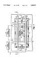
- FIG. 1is a top view of a schematic representation of the micromechanical gyroscopic transducer with improved drive and sense capabilities according to the present invention
- FIG. 2is a cross-sectional view of the gyroscopic transducer of the present invention taken along lines 2--2 of FIG. 1;
- FIG. 3is a cross-sectional view of another embodiment of the present invention taken along lines 3--3 of FIG. 1, wherein both drive and sense electrodes are defined in the bottom of the pit beneath the transducer element.
- the micromechanical gyroscopic transducer with improved drive and sense capabilitiesis shown, in a preferred embodiment, in FIG. 1 and includes a substrate 10 of preferably N-type mono- or polycrystalline silicon.
- a substrate 10of preferably N-type mono- or polycrystalline silicon.
- Selective doping and anisotropic, EDP, electrochemical, photochemical, or other selective type etchingyields the gyroscopic transducer element 12 suspended above pit 14.
- the process of silicon doping and selective etchingis well known to those skilled in the art.
- the gyroscopic transducer element 12is comprised of an outer sense gimbal 16 integral with substrate 10.
- the outer sense gimbal 16is suspended and coupled to substrate 10 by first and second flexible elements 18 and 20, respectively.
- the first and second elementsare disposed on opposite ends of the sense gimbal plate 16 and are axially aligned to permit oscillatory motion of the sense gimbal plate 16 about a sense axis 22 which passes through the first and second flexible elements.
- Gyroscopic transducer element 12also includes a drive gimbal plate 24 integral with and interior to the outer sense gimbal plate 16.
- the inner/drive gimbal plate 24is coupled to the sense gimbal plate 16 by third and fourth flexible elements 26 and 28, respectively.
- the third and fourth flexible elementsare also coupled to opposite sides or ends of drive gimbal plate 24.
- the third and fourth flexible elementsare also axially aligned to permit oscillatory motion of the drive gimbal plate about a drive axis 30 which passes through the third and fourth flexible elements 26, 28.
- the drive axis and the third and fourth flexible elementsare disposed orthogonal to the sense axis 22.
- the drive gimbal plate 24also includes a balanced inertial mass 32 generally centrally located on the drive gimbal plate.
- the inertial massmay be formed by depositing metal, such as gold, on the surface of the gimbal plate, and preferably also includes a silicon tub extending below the drive gimbal plate.
- the tubis preferably back-filled with polysilicon or a metal such as gold.
- the gyroscopic transducer of the present inventionalso includes electronics necessary to cause the drive gimbal plate to oscillate. These necessary electronics include drive electronics 34 coupled to one or more drive electrodes 36.
- the drive electrodes 36are buried electrodes formed in the bottom of the anisotropically etched pit 14. Drive electrodes 36 are formed by selectively doping the desired regions in the bottom of the pit.
- Drive electrodes 36are coupled to drive electronics 34 by means of metallization layers on the semiconductor wafer. The method of forming the buried electrodes and coupling them to the drive electronics are also well known to those skilled in the art. Additionally, various drive electronics located both on and off the semiconductor wafer itself are contemplated by the present invention and described in greater detail in U.S. Pat. No. 5,016,072.
- the present gyroscopic transduceralso includes at least one sense electrode 38 coupled to sense electronics 40 also by means of a metallization or conducting strip 41.
- sense electrode 38includes a pair of bridge electrodes disposed parallel to sense gimbal plate 16.
- the gyroscopic transducerWhen the gyroscopic transducer detects an angular rate about the input axis 42, FIG. 2, which is orthogonal to both the drive and sense axes, the gyroscopic action of the transducer initiated by the oscillating drive gimbal plate causes displacement of the sense gimbal plate 16 about the sense axis 22 as shown by arrow 44. This displacement is detected by the bridge electrodes 38. The sense electronics subsequently convert the displacement signal into an indication of angular rotation detected by the gyroscope. Most importantly, since the sense gimbal plate is the outermost gimbal plate, the bridge electrodes 38 may be placed in very close proximity to the plate, that is, within 2 to 5 microns from the plate.
- the sensitivity of the capacitive sense electronicscan be greatly increased, thus leading to a corresponding desired reduction in read-out signal noise.
- the gyroscopeis operated in a closed-loop rebalance mode wherein the sense gimbal plate is nulled about the sense axis, complete separation between the gyroscopic action of the inner drive gimbal plate which serves as the gyroscopic element from the outer sense gimbal plate is achieved, thereby resulting in a device with no conflicting geometric designs.
- the sense electrodessuch as electrode 38a, FIG. 3, may be buried electrodes similar to drive electrodes 36.
- the shown sense electrode 38ais formed in the bottom of the selectively etched pit 14 and disposed below the sense gimbal plate 16.
- Buried drive electrodes 36are first diffused through the surface 35 of wafer 37.
- a first epitaxial layer 48 of approximately 16 microns in thicknessis subsequently grown over wafer 37.
- Buried sense electrode 38ais then diffused in the first epitaxial layer 48.
- second epitaxial layer 51of approximately 8 microns in thickness as indicated by arrow 47 is grown on top of the first epitaxial layer 48.
- Sense gimbal plate 16 and the drive gimbal plateare then diffused into the surface 53 of the second epitaxial layer. Both the drive and sense gimbal plates are diffused approximately 4 microns into the second epitaxial layer. During thermal processing of the device, both the drive and sense electrodes will up-diffuse into the adjacent epitaxial regions. Thus, since buried sense electrode 38a up-diffuses approximately 2 microns, an approximately 2 micron gap indicated by arrow 50 will result after selective etching between buried sense electrode 38a and sense gimbal plate 50. Similarly, drive electrodes 36 will up-diffuse approximately 4 microns resulting in a net distance of approximately 16 microns, as indicated by arrow 49, between the buried drive electrodes and the drive gimbal plate (not shown).
- buried sense electrode 38amay be located in very close proximity to sense gimbal plate 16 since the gyroscopic action of the inner drive gimbal plate is now completely separate and distinct from the outer sense gimbal plate.
- the buried sense electrode 38amay also be used in a manner similar to the bridge sense electrode that is, in a closed-loop rebalance mode to null the sense gimbal plate and provide an indication of angular rate about the input axis.
Landscapes
- Physics & Mathematics (AREA)
- Engineering & Computer Science (AREA)
- General Physics & Mathematics (AREA)
- Radar, Positioning & Navigation (AREA)
- Remote Sensing (AREA)
- Gyroscopes (AREA)
Abstract
Description
This invention relates to micromachined gyroscopic transducers and more particularly, to a micromachined gyroscope with improved separation between drive and sense functions.
Micromechanical gyroscopic transducers which are micromachined from single unitary substrates such as single crystal or polycrystalline silicon or quartz are now well known in the art. Such micromechanical gyroscopes have the potential for achieving high sensitivity and reliability at the low cost of a mass produced device.
An exemplary gyroscopic transducer fabricated from a semiconductor wafer is disclosed in U.S. Pat. No. 5,016,072 entitled "Semiconductor Chip Gyroscopic Transducer", assigned to the assignee of the present invention.
The design of such devices seeks to optimize the performance of the device within the design constraints imposed by the choice of materials, while retaining a cost advantage.
Among the performance demands are a high signal to noise ratio in the readout or sense circuitry of the gyroscope. This high signal noise is a function of the capacitance between the stationary electrodes and the moving plate from which rate information is available. The signal to noise ratio is improved by having the largest capacitance possible and the largest change in that capacitance with rate. This translates into larger and closely spaced electrode plates.
The present invention features an improved signal to noise ratio in a double or dual gimballed micromechanical gyroscopic transducer by having the sense electrodes of the gyroscope associated with the outer gimbal plate rather than the inner gimbal plate as was done in the prior art, while the drive function is respectively transferred to the inner gimbal plate from the outer gimbal plate as was also done in the prior art. The electrodes are not then constrained by the motional requirements of the drive gimbal plate and can be closer to the sense gimbal plate and bigger.
A further advantage is that under conditions of torque restoration or rebalance to the sense plate, there is no superimposed signal from the drive motion. In particular, when the outer or sense gimbal plate is rebalanced, the inner drive gimbal plate is free to vibrate or oscillate about its supporting flexible elements without also causing rotation of the sense gimbal plate as occurred in the prior art, absent an angular rate about the input axis of the present invention. Additionally, since the sense axis is held in a truly fixed position, the sense gap, that is the gap between the sense electrodes and the outer gimbal plate, can be made very small, thus greatly increasing the sensitivity of the capacitive sense circuit, leading to a corresponding desired reduction in readout signal noise.
The present invention thus includes a dual or double gimballed micromachined gyroscopic transducer which is comprised of a substrate including a pit extending downwardly from a top surface of the substrate. A gyroscopic transducer element is suspended above the bottom of the pit. The gyroscopic transducer element comprises a sense gimbal plate which is integral with the substrate. The sense gimbal plate may take the form of a ring. The sense gimbal plate is coupled to the substrate by first and second flexible elements. A first end of each of the first and second flexible elements is coupled to opposite ends of the sense gimbal plate, while a second end of each of the first and second flexible elements is coupled to the substrate. The first and second flexible elements are axially aligned to permit oscillatory motion about a sense axis which passes through the first and second flexible elements and the sense gimbal plate.
The gyroscopic transducer element further includes a drive gimbal plate integral with and interior to the sense gimbal plate. The drive gimbal plate is coupled to the sense gimbal plate by third and fourth flexible elements. A first end of each of the third and fourth flexible elements is coupled to opposite ends of the drive gimbal plate, while a second end of each of the third and fourth flexible elements is coupled to the sense gimbal plate. Thus, the third and fourth flexible elements are also axially aligned to permit oscillatory motion of the drive gimbal plate about a drive axis which passes through the third and fourth flexible elements. The drive axis and therefore, the third and fourth flexible elements, are disposed orthogonal to the sense axis and the first and second flexible elements. The drive gimbal plate further includes a balanced mass generally centrally located on the drive gimbal plate.
The micromechanical gyroscopic transducer with improved drive and sense capability according to the present invention also includes means for causing the drive gimbal plate to oscillate about the drive axis. This means includes at least one drive electrode, coupled to circuitry for energizing the drive electrode. The drive electrode is disposed in spaced relationship to at least a portion of the drive gimbal plate. Together, the energizing circuitry and the at least one drive electrode are operative for causing the drive gimbal plate to oscillate about the drive axis. In the preferred embodiment, the drive gimbal plate is caused to oscillate near or at its resonant frequency.
The gyroscopic transducer of the present invention also includes means for sensing rotation of the sense gimbal plate, including at least one sense electrode, coupled to an electronic circuit for sensing rotation of the sense gimbal plate. The sense electrode is disposed in spaced relationship to at least a portion of the sense gimbal plate. The sense electrode is further disposed so as not to be in close proximity to, and interfere with free oscillatory motion of, the drive gimbal plate. Thus, the sensing circuit and the at least one sense electrode are operative for sensing rotation of the sense gimbal plate about the sense axis, and for providing an indication of angular rotation of the transducer about an input axis orthogonal to the drive and sense axes and which is detected by the gyroscopic transducer.
In the preferred embodiment, the at least one sense electrode includes a pair of bridge electrodes disposed parallel to the sense gimbal plate and to the sense axis, for preventing interference with the oscillation of the drive gimbal plate about the drive axis. In the preferred embodiment, the drive electrode typically includes a pair of buried electrodes integral with the bottom region of the pit.
In an alternative embodiment, both the drive and sense electrodes are located in the bottom region of the pit. In such an embodiment, the drive and sense electrodes may cross or intersect, with an intervening layer of insulative semiconductor material separating the two electrodes. In this embodiment, the sense electrode is located at the topmost region of the bottom of the pit, approximately 2 to 5 microns from the sense gimbal plate, while the drive electrode is located within approximately 10 to 30 microns below the drive gimbal plate.
Also in the preferred embodiment, the gyroscopic transducer of the present invention is fabricated from a single or monolithic semiconductor wafer. Accordingly, the drive and sense gimbal plates as well as the first through fourth flexible elements are defined by doping to make these elements resistant to selective etching such as anisotropic, EDP, electrochemical and photochemical etching. After doping the desired regions, a selective etching defines the pit region beneath the gimbal plates as well as the gimbal plates and connecting flexible elements.
These, and other features and advantages of the present invention will be better understood by reading the following detailed description taken together with the drawings, wherein:
FIG. 1 is a top view of a schematic representation of the micromechanical gyroscopic transducer with improved drive and sense capabilities according to the present invention;
FIG. 2 is a cross-sectional view of the gyroscopic transducer of the present invention taken alonglines 2--2 of FIG. 1; and
FIG. 3 is a cross-sectional view of another embodiment of the present invention taken alonglines 3--3 of FIG. 1, wherein both drive and sense electrodes are defined in the bottom of the pit beneath the transducer element.
The micromechanical gyroscopic transducer with improved drive and sense capabilities according to the present invention is shown, in a preferred embodiment, in FIG. 1 and includes asubstrate 10 of preferably N-type mono- or polycrystalline silicon. Selective doping and anisotropic, EDP, electrochemical, photochemical, or other selective type etching yields thegyroscopic transducer element 12 suspended abovepit 14. The process of silicon doping and selective etching is well known to those skilled in the art.
Thegyroscopic transducer element 12 is comprised of anouter sense gimbal 16 integral withsubstrate 10. Theouter sense gimbal 16 is suspended and coupled tosubstrate 10 by first and secondflexible elements sense gimbal plate 16 and are axially aligned to permit oscillatory motion of thesense gimbal plate 16 about asense axis 22 which passes through the first and second flexible elements.
The gyroscopic transducer of the present invention also includes electronics necessary to cause the drive gimbal plate to oscillate. These necessary electronics includedrive electronics 34 coupled to one ormore drive electrodes 36. In the preferred embodiment, thedrive electrodes 36 are buried electrodes formed in the bottom of the anisotropically etchedpit 14. Driveelectrodes 36 are formed by selectively doping the desired regions in the bottom of the pit. Driveelectrodes 36 are coupled to driveelectronics 34 by means of metallization layers on the semiconductor wafer. The method of forming the buried electrodes and coupling them to the drive electronics are also well known to those skilled in the art. Additionally, various drive electronics located both on and off the semiconductor wafer itself are contemplated by the present invention and described in greater detail in U.S. Pat. No. 5,016,072.
The present gyroscopic transducer also includes at least onesense electrode 38 coupled to senseelectronics 40 also by means of a metallization or conductingstrip 41. In the preferred embodiment,sense electrode 38 includes a pair of bridge electrodes disposed parallel to sensegimbal plate 16.
The advantages of the gyroscopic transducer with improved drive and sense capabilities of the present invention will be better understood by referring to the operation of the transducer in which driveelectronics 34 energizedrive electrodes 36 and cause the inner/drive gimbal plate 24 to oscillate about thedrive axis 30. Since there is no bridge electrode above thedrive gimbal plate 24, the drive plate, which also serves as the gyroscopic element, may freely rotate about the drive axis without interference from overhead bridge electrodes as in the prior art.
When the gyroscopic transducer detects an angular rate about theinput axis 42, FIG. 2, which is orthogonal to both the drive and sense axes, the gyroscopic action of the transducer initiated by the oscillating drive gimbal plate causes displacement of thesense gimbal plate 16 about thesense axis 22 as shown byarrow 44. This displacement is detected by thebridge electrodes 38. The sense electronics subsequently convert the displacement signal into an indication of angular rotation detected by the gyroscope. Most importantly, since the sense gimbal plate is the outermost gimbal plate, thebridge electrodes 38 may be placed in very close proximity to the plate, that is, within 2 to 5 microns from the plate.
Thus, by greatly reducing the distance between the bridge sense electrodes and the sense gimbal plate, referred to as the "sense gap," the sensitivity of the capacitive sense electronics can be greatly increased, thus leading to a corresponding desired reduction in read-out signal noise. Further, when the gyroscope is operated in a closed-loop rebalance mode wherein the sense gimbal plate is nulled about the sense axis, complete separation between the gyroscopic action of the inner drive gimbal plate which serves as the gyroscopic element from the outer sense gimbal plate is achieved, thereby resulting in a device with no conflicting geometric designs.
In another embodiment of the present invention, the sense electrodes such aselectrode 38a, FIG. 3, may be buried electrodes similar to driveelectrodes 36. In this embodiment, the shownsense electrode 38a is formed in the bottom of the selectively etchedpit 14 and disposed below thesense gimbal plate 16.
By only lightly doping the drive and sense electrodes to a level of approximately 5×10-18 ions/cm2, and doping the N epitaxial regions to as high a level as possible, limited only by reverse voltage breakdown, subsequent processing of the gyroscopic transducer device will not cause the bridge and sense electrodes to diffuse into one another, as would happen with heavily doped areas.
Thus, as with the bridge sense electrode, buriedsense electrode 38a may be located in very close proximity to sensegimbal plate 16 since the gyroscopic action of the inner drive gimbal plate is now completely separate and distinct from the outer sense gimbal plate. The buriedsense electrode 38a may also be used in a manner similar to the bridge sense electrode that is, in a closed-loop rebalance mode to null the sense gimbal plate and provide an indication of angular rate about the input axis.
Other embodiments, modifications and substitutions by those of ordinary skill in the art are considered to be within the scope of the present invention, which is not to be limited except by the claims which follow.
Claims (8)
1. A dual gimbal micromachined gyroscopic transducer comprising:
a substrate including a pit having a bottom region, said pit extending downwardly from a top surface of said substrate;
a gyroscopic transducer element suspended above the bottom region of said pit, said gyroscopic transducer element comprising:
a sense gimbal plate integral with said substrate, said sense gimbal plate coupled to said substrate by first and second flexible elements, a first end of each of said first and second flexible elements coupled to opposite ends of said sense gimbal plate, and a second end of each of said first and second flexible elements coupled to said substrate, said first and second flexible elements axially aligned to permit oscillatory motion about a sense axis which passes through said first and second flexible elements;
a drive gimbal plate integral with and interior to said sense gimbal plate, said drive gimbal plate coupled to said sense gimbal plate by third and fourth flexible elements, a first end of each of said third and fourth flexible elements coupled to opposite ends of said drive gimbal plate, and a second end of each of said third and fourth flexible elements coupled to said sense gimbal plate, said third and fourth flexible elements axially aligned to permit oscillatory motion about a drive axis which passes through said third and fourth flexible elements, said drive axis disposed orthogonal to said sense axis, said drive gimbal plate further including a balanced mass generally centrally located on said drive gimbal plate;
means for oscillating said drive gimbal plate including at least one drive electrode, coupled to means for energizing said drive electrode, said at least one drive electrode disposed in spaced relationship to at least a portion of said drive gimbal plate, said means for energizing said at least one drive electrode operative for causing said drive gimbal plate to oscillate about said drive axis; and
means for sensing rotation of said sense gimbal plate, said means for sensing including at least one sense electrode, coupled to said means for sensing rotation of said sense gimbal plate, said at least one sense electrode disposed in spaced relationship to at least a portion of said sense gimbal plate, said at least one sense electrode disposed so as not to be in close proximity to, and interfere with free oscillatory motion of said drive gimbal plate, said means for sensing and said at least one sense electrode operative for sensing rotation of said sense gimbal plate about said sense axis, said means for sensing for providing an indication of angular rotation detected by said gyroscopic transducer about an input axis orthogonal to said drive and sense axes.
2. The gyroscopic transducer of claim 1 wherein said at least one drive electrode includes a buried electrode integral with said bottom region of said pit.
3. The gyroscopic transducer of claim 1 wherein said at least one sense electrode includes at least one buried electrode integral with said bottom region of said pit.
4. The gyroscopic transducer of claim 1 wherein said substrate includes a semiconductor material; and
wherein said drive and sense gimbal plates, and said first, second, third and fourth flexible elements are doped to resist selective etching.
5. The gyroscopic transducer of claim 4
wherein said pit, said drive and sense gimbal plates, and said first, second, third and fourth flexible elements are defined from said semiconductor material utilizing selective etching.
6. The gyroscopic transducer of claim 1 wherein said means for oscillating said drive gimbal plate causes said drive gimbal plate to oscillate at the resonant frequency of the drive gimbal plate.
7. A dual gimbal micromachined gyroscopic transducer comprising:
a substrate including a pit having a bottom region, said pit extending downwardly from a top surface of said substrate;
a gyroscopic transducer element suspended above the bottom region of said pit, said gyroscopic transducer element comprising:
a sense gimbal plate integral with said substrate, said sense gimbal plate coupled to said substrate by first and second flexible elements, a first end of each of said first and second flexible elements Coupled to opposite ends of said sense gimbal plate, and a second end of each of said first and second flexible elements coupled to said substrate, said first and second flexible elements axially aligned to permit oscillatory motion about a sense axis which passes through said first and second flexible elements;
a drive gimbal plate integral with and interior to said sense gimbal plate, said drive gimbal plate coupled to said sense gimbal plate by third and fourth flexible elements, a first end of each of said third and fourth flexible elements coupled to opposite ends of said drive gimbal plate, and a second end of each of said third and fourth flexible elements coupled to said sense gimbal plate, said third and fourth flexible elements axially aligned to permit oscillatory motion about a drive axis which passes through said third and fourth flexible elements, said drive axis disposed orthogonal to said sense axis, said drive gimbal plate further including a balanced mass generally centrally located on said drive gimbal plate;
means for oscillating said drive gimbal plate including at least one drive electrode, coupled to means for energizing said drive electrode, said at least one drive electrode disposed in spaced relationship to at least a portion of said drive gimbal plate, said means for energizing said at least one drive electrode operative for causing said drive gimbal plate to oscillate about said drive axis; and
means for sensing rotation of said sense gimbal plate, said means for sensing including at least one sense electrode, coupled to said means for sensing rotation of said sense gimbal plate, said at least one sense electrode disposed in spaced relationship to at least a portion of said sense gimbal plate, said at least one sense electrode disposed so as not to be in close proximity to, and interfere with free oscillatory motion of said drive gimbal plate, said means for sensing and said at least one sense electrode operative for sensing rotation of said sense gimbal plate about said sense axis, said means for sensing for providing an indication of angular rotation detected by said gyroscopic transducer about an input axis orthogonal to said drive and sense axes,
wherein said at least one sense electrode includes at least one bridge sense electrode; and
wherein said at least one bridge sense electrode is disposed parallel to said sense gimbal plate and to said sense axis, for preventing interference with the oscillation of said drive gimbal plate about said drive axis by said at least one bridge sense electrode.
8. The gyroscopic transducer of claim 7 wherein said at least one bridge sense electrode disposed in spaced relationship to at least a portion of said sense gimbal plate is disposed a predetermined distance in the range of 2 to 5 microns from said sense gimbal plate.
Priority Applications (2)
| Application Number | Priority Date | Filing Date | Title |
|---|---|---|---|
| US07/851,913US5408877A (en) | 1992-03-16 | 1992-03-16 | Micromechanical gyroscopic transducer with improved drive and sense capabilities |
| US08/425,857US5515724A (en) | 1992-03-16 | 1995-04-20 | Micromechanical gyroscopic transducer with improved drive and sense capabilities |
Applications Claiming Priority (1)
| Application Number | Priority Date | Filing Date | Title |
|---|---|---|---|
| US07/851,913US5408877A (en) | 1992-03-16 | 1992-03-16 | Micromechanical gyroscopic transducer with improved drive and sense capabilities |
Related Child Applications (1)
| Application Number | Title | Priority Date | Filing Date |
|---|---|---|---|
| US08/425,857ContinuationUS5515724A (en) | 1992-03-16 | 1995-04-20 | Micromechanical gyroscopic transducer with improved drive and sense capabilities |
Publications (1)
| Publication Number | Publication Date |
|---|---|
| US5408877Atrue US5408877A (en) | 1995-04-25 |
Family
ID=25312036
Family Applications (2)
| Application Number | Title | Priority Date | Filing Date |
|---|---|---|---|
| US07/851,913Expired - LifetimeUS5408877A (en) | 1992-03-16 | 1992-03-16 | Micromechanical gyroscopic transducer with improved drive and sense capabilities |
| US08/425,857Expired - LifetimeUS5515724A (en) | 1992-03-16 | 1995-04-20 | Micromechanical gyroscopic transducer with improved drive and sense capabilities |
Family Applications After (1)
| Application Number | Title | Priority Date | Filing Date |
|---|---|---|---|
| US08/425,857Expired - LifetimeUS5515724A (en) | 1992-03-16 | 1995-04-20 | Micromechanical gyroscopic transducer with improved drive and sense capabilities |
Country Status (1)
| Country | Link |
|---|---|
| US (2) | US5408877A (en) |
Cited By (39)
| Publication number | Priority date | Publication date | Assignee | Title |
|---|---|---|---|---|
| US5530342A (en)* | 1994-09-30 | 1996-06-25 | Rockwell International Corporation | Micromachined rate sensor comb drive device and method |
| US5600065A (en)* | 1995-10-25 | 1997-02-04 | Motorola, Inc. | Angular velocity sensor |
| US5638946A (en)* | 1996-01-11 | 1997-06-17 | Northeastern University | Micromechanical switch with insulated switch contact |
| WO1997024578A1 (en)* | 1995-12-27 | 1997-07-10 | Tovarischestvo S Ogranichennoi Otvetstvennostju Nauchno-Proizvodstvennaya Kompania 'vektor' | Micromechanical vibration gyroscope |
| DE19745083A1 (en)* | 1997-10-11 | 1999-04-15 | Bodenseewerk Geraetetech | Rotation rate sensor using Coriolis effect |
| US5914801A (en)* | 1996-09-27 | 1999-06-22 | Mcnc | Microelectromechanical devices including rotating plates and related methods |
| US5955668A (en)* | 1997-01-28 | 1999-09-21 | Irvine Sensors Corporation | Multi-element micro gyro |
| US5955932A (en)* | 1992-12-11 | 1999-09-21 | The Regents Of The University Of California | Q-controlled microresonators and tunable electric filters using such resonators |
| US5992233A (en)* | 1996-05-31 | 1999-11-30 | The Regents Of The University Of California | Micromachined Z-axis vibratory rate gyroscope |
| WO2000029855A1 (en)* | 1998-10-14 | 2000-05-25 | Irvine Sensors Corporation | Multi-element micro-gyro |
| US6128953A (en)* | 1992-10-13 | 2000-10-10 | Nippondenso Co., Ltd | Dynamical quantity sensor |
| US6250156B1 (en) | 1996-05-31 | 2001-06-26 | The Regents Of The University Of California | Dual-mass micromachined vibratory rate gyroscope |
| US6275320B1 (en) | 1999-09-27 | 2001-08-14 | Jds Uniphase, Inc. | MEMS variable optical attenuator |
| WO2001079862A1 (en)* | 2000-04-14 | 2001-10-25 | Microsensors, Inc. | Z-axis micro-gyro |
| US6373682B1 (en) | 1999-12-15 | 2002-04-16 | Mcnc | Electrostatically controlled variable capacitor |
| US6377438B1 (en) | 2000-10-23 | 2002-04-23 | Mcnc | Hybrid microelectromechanical system tunable capacitor and associated fabrication methods |
| US6396620B1 (en) | 2000-10-30 | 2002-05-28 | Mcnc | Electrostatically actuated electromagnetic radiation shutter |
| US6485273B1 (en) | 2000-09-01 | 2002-11-26 | Mcnc | Distributed MEMS electrostatic pumping devices |
| US6494094B1 (en) | 1999-11-01 | 2002-12-17 | Mitsubishi Denki Kabushiki Kaisha | Angular rate sensor |
| US6497148B1 (en)* | 1999-09-08 | 2002-12-24 | Alps Electric Co., Ltd. | Gyroscope and input apparatus using the same |
| WO2002103365A2 (en) | 2001-06-19 | 2002-12-27 | Microsensors, Inc. | Mems sensor with single central anchor and motion-limiting connection geometry |
| US6584840B2 (en) | 2001-03-30 | 2003-07-01 | Mitsubishi Denki Kabushiki Kaisha | Angular velocity sensor |
| US6590267B1 (en) | 2000-09-14 | 2003-07-08 | Mcnc | Microelectromechanical flexible membrane electrostatic valve device and related fabrication methods |
| US20040011130A1 (en)* | 2000-08-18 | 2004-01-22 | Karin Bauer | Micromechanical speed sensor and a method for the production thereof |
| US6715352B2 (en) | 2001-06-26 | 2004-04-06 | Microsensors, Inc. | Method of designing a flexure system for tuning the modal response of a decoupled micromachined gyroscope and a gyroscoped designed according to the method |
| US20040065638A1 (en)* | 2002-10-07 | 2004-04-08 | Bishnu Gogoi | Method of forming a sensor for detecting motion |
| US20040069062A1 (en)* | 2002-10-12 | 2004-04-15 | Cho Jin-Woo | Microgyroscope tunable for translational acceleration |
| US20040083812A1 (en)* | 2002-11-04 | 2004-05-06 | Toshihiko Ichinose | Z-axis vibration gyroscope |
| US20040222647A1 (en)* | 2003-05-07 | 2004-11-11 | Smith Kelly K. | Low profile mechanical assist hood latch |
| US20050056094A1 (en)* | 2002-02-06 | 2005-03-17 | Geen John A. | Micromachined apparatus utilizing box suspensions |
| US20050139005A1 (en)* | 2002-02-06 | 2005-06-30 | Analog Devices, Inc. | Micromachined sensor with quadrature suppression |
| US20050229705A1 (en)* | 2004-04-14 | 2005-10-20 | Geen John A | Inertial sensor with a linear array of sensor elements |
| US20060016481A1 (en)* | 2004-07-23 | 2006-01-26 | Douglas Kevin R | Methods of operating microvalve assemblies and related structures and related devices |
| US20060144174A1 (en)* | 2004-10-01 | 2006-07-06 | Geen John A | Common centroid micromachine driver |
| US7421897B2 (en) | 2005-04-14 | 2008-09-09 | Analog Devices, Inc. | Cross-quad and vertically coupled inertial sensors |
| US20110265565A1 (en)* | 2010-04-30 | 2011-11-03 | Qualcomm Mems Technologies, Inc. | Micromachined piezoelectric X-axis gyroscope |
| CN102679967A (en)* | 2012-05-07 | 2012-09-19 | 上海交通大学 | Piezoelectric biaxial micro gyroscope with rocking mass block |
| US20120297873A1 (en)* | 2011-05-23 | 2012-11-29 | Senodia Technologies (Shanghai) Co., Ltd. | Mems devices sensing both rotation and acceleration |
| EP3347674B1 (en)* | 2015-09-09 | 2020-07-15 | Murata Manufacturing Co., Ltd. | An electrode for a microelectromechanical device |
Families Citing this family (7)
| Publication number | Priority date | Publication date | Assignee | Title |
|---|---|---|---|---|
| US5945599A (en)* | 1996-12-13 | 1999-08-31 | Kabushiki Kaisha Toyota Chuo Kenkyusho | Resonance type angular velocity sensor |
| ATE254715T1 (en)* | 1999-01-13 | 2003-12-15 | Vermeer Mfg Co | AUTOMATED DRILLING PLANNING METHOD AND APPARATUS FOR HORIZONTAL DIRECTIONAL DRILLING |
| US6315062B1 (en) | 1999-09-24 | 2001-11-13 | Vermeer Manufacturing Company | Horizontal directional drilling machine employing inertial navigation control system and method |
| KR100373484B1 (en)* | 2000-01-27 | 2003-02-25 | 국방과학연구소 | vibrating micromachined gyroscope |
| US7421898B2 (en)* | 2004-08-16 | 2008-09-09 | The Regents Of The University Of California | Torsional nonresonant z-axis micromachined gyroscope with non-resonant actuation to measure the angular rotation of an object |
| JP7276008B2 (en)* | 2019-08-29 | 2023-05-18 | セイコーエプソン株式会社 | Vibration devices, electronic equipment and moving bodies |
| ES2820674A1 (en)* | 2020-02-28 | 2021-04-21 | Stockholm Prec Tools S L | TOOL, SYSTEM AND PROCEDURE FOR THE ORIENTATION OF CORE SAMPLES IN THE DRILLING OF WELLS (Machine-translation by Google Translate, not legally binding) |
Citations (100)
| Publication number | Priority date | Publication date | Assignee | Title |
|---|---|---|---|---|
| US3053095A (en)* | 1957-07-20 | 1962-09-11 | Bolkow Entwicklungen Kg | Apparatus for measuring and regulating very low speeds |
| US3251231A (en)* | 1961-07-11 | 1966-05-17 | Hunt Geoffrey Harold | Gyroscope apparatus |
| US3370458A (en)* | 1965-09-10 | 1968-02-27 | W C Dillon & Company Inc | Mechanical force gauge |
| US3696429A (en)* | 1971-05-24 | 1972-10-03 | Cutler Hammer Inc | Signal cancellation system |
| US3913035A (en)* | 1974-07-01 | 1975-10-14 | Motorola Inc | Negative resistance high-q-microwave oscillator |
| US4044305A (en)* | 1975-03-17 | 1977-08-23 | The Charles Stark Draper Laboratory, Inc. | Apparatus for providing a displacement representative of the magnitude of a signal |
| US4122448A (en)* | 1977-07-21 | 1978-10-24 | Westinghouse Electric Corp. | Automatic phase and gain balance controller for a baseband processor |
| US4144764A (en)* | 1978-05-11 | 1979-03-20 | Schaevitz Engineering | Servo amplifier for an electrically damped accelerometer |
| US4155257A (en)* | 1977-05-23 | 1979-05-22 | The Singer Company | Temperature compensated vibrating beam accelerometer |
| US4234666A (en)* | 1978-07-26 | 1980-11-18 | Western Electric Company, Inc. | Carrier tapes for semiconductor devices |
| US4321500A (en)* | 1979-12-17 | 1982-03-23 | Paroscientific, Inc. | Longitudinal isolation system for flexurally vibrating force transducers |
| US4336718A (en)* | 1980-09-08 | 1982-06-29 | Lear Siegler, Inc. | Control circuit for accelerometer |
| US4342227A (en)* | 1980-12-24 | 1982-08-03 | International Business Machines Corporation | Planar semiconductor three direction acceleration detecting device and method of fabrication |
| US4381672A (en)* | 1981-03-04 | 1983-05-03 | The Bendix Corporation | Vibrating beam rotation sensor |
| US4406992A (en)* | 1981-04-20 | 1983-09-27 | Kulite Semiconductor Products, Inc. | Semiconductor pressure transducer or other product employing layers of single crystal silicon |
| US4411741A (en)* | 1982-01-12 | 1983-10-25 | University Of Utah | Apparatus and method for measuring the concentration of components in fluids |
| US4414852A (en)* | 1981-09-14 | 1983-11-15 | Gould Inc. | Automatic zero balance circuit |
| US4447753A (en)* | 1981-03-25 | 1984-05-08 | Seiko Instruments & Electronics Ltd. | Miniature GT-cut quartz resonator |
| US4468584A (en)* | 1976-10-01 | 1984-08-28 | Sharp Kabushiki Kaisha | Unidirectional flexure type tuning fork crystal vibrator |
| US4478077A (en)* | 1982-09-30 | 1984-10-23 | Honeywell Inc. | Flow sensor |
| US4478076A (en)* | 1982-09-30 | 1984-10-23 | Honeywell Inc. | Flow sensor |
| US4483194A (en)* | 1981-07-02 | 1984-11-20 | Centre Electronique Horloger S.A. | Accelerometer |
| US4484382A (en)* | 1981-05-15 | 1984-11-27 | Seiko Instruments & Electronics Ltd. | Method of adjusting resonant frequency of a coupling resonator |
| US4490772A (en)* | 1983-06-13 | 1984-12-25 | Blickstein Martin J | Voltage and mechanically variable trimmer capacitor |
| US4495499A (en)* | 1981-09-08 | 1985-01-22 | David Richardson | Integrated oscillator-duplexer-mixer |
| US4499778A (en)* | 1981-02-03 | 1985-02-19 | Northrop Corporation | Flexure mount assembly for a dynamically tuned gyroscope and method of manufacturing same |
| US4502042A (en)* | 1981-03-30 | 1985-02-26 | M.A.N.-Roland Druckmaschinen Aktiengesellschaft | Proximity switch, which indicates the presence or absence of field changing objects at a defined distance from the proximity switch by a binary signal with the aid of excitation and detection of a field |
| US4522072A (en)* | 1983-04-22 | 1985-06-11 | Insouth Microsystems, Inc. | Electromechanical transducer strain sensor arrangement and construction |
| US4524619A (en)* | 1984-01-23 | 1985-06-25 | Piezoelectric Technology Investors, Limited | Vibratory angular rate sensor system |
| US4538461A (en)* | 1984-01-23 | 1985-09-03 | Piezoelectric Technology Investors, Inc. | Vibratory angular rate sensing system |
| US4585083A (en)* | 1983-11-01 | 1986-04-29 | Shinko Denshi Company Ltd. | Mechanism for detecting load |
| US4590801A (en)* | 1983-09-02 | 1986-05-27 | Sundstrand Data Control, Inc. | Apparatus for measuring inertial specific force and angular rate of a moving body |
| US4592242A (en)* | 1982-04-14 | 1986-06-03 | Bodenseewerk Geratetechnik Gmbh | Dynamically tuned gimbal suspension with flexural pivots for a two-degree-of-freedom gyro |
| US4596158A (en)* | 1983-01-05 | 1986-06-24 | Litton Systems, Inc. | Tuned gyroscope with dynamic absorber |
| US4598585A (en)* | 1984-03-19 | 1986-07-08 | The Charles Stark Draper Laboratory, Inc. | Planar inertial sensor |
| US4600934A (en)* | 1984-01-06 | 1986-07-15 | Harry E. Aine | Method of undercut anisotropic etching of semiconductor material |
| US4619001A (en)* | 1983-08-02 | 1986-10-21 | Matsushita Electric Industrial Co., Ltd. | Tuning systems on dielectric substrates |
| US4621925A (en)* | 1982-11-11 | 1986-11-11 | Fujitsu Limited | Fiber-optic gyro |
| US4628283A (en)* | 1983-11-07 | 1986-12-09 | The Narda Microwave Corporation | Hermetically sealed oscillator with dielectric resonator tuned through dielectric window by adjusting screw |
| US4629957A (en)* | 1984-03-27 | 1986-12-16 | Emi Limited | Sensing apparatus |
| US4639690A (en)* | 1985-07-05 | 1987-01-27 | Litton Systems, Inc. | Tunable, dielectric-resonator-stabilized oscillator and method of tuning same |
| US4644793A (en)* | 1984-09-07 | 1987-02-24 | The Marconi Company Limited | Vibrational gyroscope |
| US4651564A (en)* | 1982-09-30 | 1987-03-24 | Honeywell Inc. | Semiconductor device |
| US4653326A (en)* | 1984-01-12 | 1987-03-31 | Commissariat A L'energie Atomique | Directional accelerometer and its microlithographic fabrication process |
| US4654663A (en)* | 1981-11-16 | 1987-03-31 | Piezoelectric Technology Investors, Ltd. | Angular rate sensor system |
| US4670092A (en)* | 1986-04-18 | 1987-06-02 | Rockwell International Corporation | Method of fabricating a cantilever beam for a monolithic accelerometer |
| US4671112A (en)* | 1984-03-22 | 1987-06-09 | Matsushita Electric Industrial Co., Ltd. | Angular velocity sensor |
| US4674180A (en)* | 1984-05-01 | 1987-06-23 | The Foxboro Company | Method of making a micromechanical electric shunt |
| US4674319A (en)* | 1985-03-20 | 1987-06-23 | The Regents Of The University Of California | Integrated circuit sensor |
| US4680606A (en)* | 1984-06-04 | 1987-07-14 | Tactile Perceptions, Inc. | Semiconductor transducer |
| US4679434A (en)* | 1985-07-25 | 1987-07-14 | Litton Systems, Inc. | Integrated force balanced accelerometer |
| US4699006A (en)* | 1984-03-19 | 1987-10-13 | The Charles Stark Draper Laboratory, Inc. | Vibratory digital integrating accelerometer |
| US4705659A (en)* | 1985-04-01 | 1987-11-10 | Motorola, Inc. | Carbon film oxidation for free-standing film formation |
| US4706374A (en)* | 1984-10-19 | 1987-11-17 | Nissan Motor Co., Ltd. | Method of manufacture for semiconductor accelerometer |
| US4712439A (en)* | 1986-02-24 | 1987-12-15 | Henry North | Apparatus for producing a force |
| US4727752A (en)* | 1987-02-04 | 1988-03-01 | Sundstrand Data Control, Inc. | Pseudosinusoidal oscillator drive system |
| US4735506A (en)* | 1985-04-01 | 1988-04-05 | Litton Systems, Inc. | Phase nulling optical gyroscope |
| US4736629A (en)* | 1985-12-20 | 1988-04-12 | Silicon Designs, Inc. | Micro-miniature accelerometer |
| US4743789A (en)* | 1987-01-12 | 1988-05-10 | Puskas William L | Variable frequency drive circuit |
| US4744248A (en)* | 1985-07-25 | 1988-05-17 | Litton Systems, Inc. | Vibrating accelerometer-multisensor |
| US4744249A (en)* | 1985-07-25 | 1988-05-17 | Litton Systems, Inc. | Vibrating accelerometer-multisensor |
| US4747312A (en)* | 1986-02-21 | 1988-05-31 | Fischer & Porter Co. | Double-loop Coriolis type mass flowmeter |
| US4750364A (en)* | 1985-10-21 | 1988-06-14 | Hitachi, Ltd. | Angular velocity and acceleration sensor |
| US4761743A (en)* | 1985-12-02 | 1988-08-02 | The Singer Company | Dynamic system analysis in a vibrating beam accelerometer |
| US4764244A (en)* | 1985-06-11 | 1988-08-16 | The Foxboro Company | Resonant sensor and method of making same |
| US4776924A (en)* | 1986-10-02 | 1988-10-11 | Commissariat A L'energie Atomique | Process for the production of a piezoresistive gauge and to an accelerometer incorporating such a gauge |
| US4783237A (en)* | 1983-12-01 | 1988-11-08 | Harry E. Aine | Solid state transducer and method of making same |
| US4789803A (en)* | 1987-08-04 | 1988-12-06 | Sarcos, Inc. | Micropositioner systems and methods |
| US4792676A (en)* | 1985-10-22 | 1988-12-20 | Kabushiki Kaisha Tokyo Keiki | Gyro apparatus with a vibration portion |
| US4805456A (en)* | 1987-05-19 | 1989-02-21 | Massachusetts Institute Of Technology | Resonant accelerometer |
| US4808948A (en)* | 1987-09-28 | 1989-02-28 | Kulicke And Soffa Indusries, Inc. | Automatic tuning system for ultrasonic generators |
| US4834538A (en)* | 1987-03-19 | 1989-05-30 | Stc Plc | Fibre optic gyroscope with nulling feedback control loop |
| USRE32931E (en)* | 1984-01-23 | 1989-05-30 | Piezoelectric Technology Investors, Inc. | Vibratory angular rate sensor system |
| US4851080A (en)* | 1987-06-29 | 1989-07-25 | Massachusetts Institute Of Technology | Resonant accelerometer |
| US4855544A (en)* | 1988-09-01 | 1989-08-08 | Honeywell Inc. | Multiple level miniature electromechanical accelerometer switch |
| US4869107A (en)* | 1986-08-06 | 1989-09-26 | Nissan Motor Co., Ltd. | Acceleration sensor for use in automotive vehicle |
| US4882933A (en)* | 1988-06-03 | 1989-11-28 | Novasensor | Accelerometer with integral bidirectional shock protection and controllable viscous damping |
| US4884446A (en)* | 1987-03-12 | 1989-12-05 | Ljung Per B | Solid state vibrating gyro |
| US4890812A (en)* | 1988-02-01 | 1990-01-02 | Litton Systems, Inc. | Temperature compensated mount for supporting a ring laser gyro |
| US4893509A (en)* | 1988-12-27 | 1990-01-16 | General Motors Corporation | Method and product for fabricating a resonant-bridge microaccelerometer |
| US4898032A (en)* | 1987-07-08 | 1990-02-06 | Thorn Emi Electronics Limited | Rate sensor |
| GB2183040B (en) | 1985-11-19 | 1990-02-07 | Stc Plc | Transducer |
| US4900971A (en)* | 1988-03-10 | 1990-02-13 | Seiko Electronic Components Ltd. | Face shear mode quartz crystal resonator |
| US4899587A (en)* | 1984-01-23 | 1990-02-13 | Piezoelectric Technology Investors, Limited | Method for sensing rotation using vibrating piezoelectric elements |
| US4901586A (en)* | 1989-02-27 | 1990-02-20 | Sundstrand Data Control, Inc. | Electrostatically driven dual vibrating beam force transducer |
| US4916520A (en)* | 1987-09-24 | 1990-04-10 | Nec Corporation | Semiconductor device with airbridge interconnection |
| US4922756A (en)* | 1988-06-20 | 1990-05-08 | Triton Technologies, Inc. | Micro-machined accelerometer |
| US4929860A (en)* | 1988-05-17 | 1990-05-29 | Sundstrand Data Control, Inc. | Electrode configuration for vibrating beam transducers |
| USRE33479E (en)* | 1984-01-23 | 1990-12-11 | Piezoelectric Technology Investors | Vibratory angular rate sensing system |
| US4981359A (en)* | 1989-06-19 | 1991-01-01 | Litton Systems, Inc. | Ring laser gyroscope dither drive system and method |
| US5001383A (en)* | 1988-09-09 | 1991-03-19 | Seiko Electronic Components Ltd. | Longitudinal quartz crystal resonator |
| US5016072A (en)* | 1988-01-13 | 1991-05-14 | The Charles Stark Draper Laboratory, Inc. | Semiconductor chip gyroscopic transducer |
| US5090809A (en)* | 1990-06-04 | 1992-02-25 | Ferrar Carl M | Modulation frequency control in a fiber optic rotation sensor |
| US5094537A (en)* | 1991-03-08 | 1992-03-10 | Honeywell Inc. | Signal processing system for correcting ring laser gyroscope readout |
| US5138883A (en)* | 1989-09-29 | 1992-08-18 | Minister Of National Defence Of Her Majesty's Canadian Government | Analog torque rebalance loop for a tuned rotor gyroscope |
| US5195371A (en)* | 1988-01-13 | 1993-03-23 | The Charles Stark Draper Laboratory, Inc. | Semiconductor chip transducer |
| US5205171A (en)* | 1991-01-11 | 1993-04-27 | Northrop Corporation | Miniature silicon accelerometer and method |
| US5226321A (en)* | 1990-05-18 | 1993-07-13 | British Aerospace Public Limited Company | Vibrating planar gyro |
| US5233874A (en)* | 1991-08-19 | 1993-08-10 | General Motors Corporation | Active microaccelerometer |
| US5241861A (en)* | 1991-02-08 | 1993-09-07 | Sundstrand Corporation | Micromachined rate and acceleration sensor |
Family Cites Families (4)
| Publication number | Priority date | Publication date | Assignee | Title |
|---|---|---|---|---|
| US5216490A (en) | 1988-01-13 | 1993-06-01 | Charles Stark Draper Laboratory, Inc. | Bridge electrodes for microelectromechanical devices |
| US5060039A (en)* | 1988-01-13 | 1991-10-22 | The Charles Stark Draper Laboratory, Inc. | Permanent magnet force rebalance micro accelerometer |
| US5025346A (en)* | 1989-02-17 | 1991-06-18 | Regents Of The University Of California | Laterally driven resonant microstructures |
| US5203208A (en)* | 1991-04-29 | 1993-04-20 | The Charles Stark Draper Laboratory | Symmetrical micromechanical gyroscope |
- 1992
- 1992-03-16USUS07/851,913patent/US5408877A/ennot_activeExpired - Lifetime
- 1995
- 1995-04-20USUS08/425,857patent/US5515724A/ennot_activeExpired - Lifetime
Patent Citations (101)
| Publication number | Priority date | Publication date | Assignee | Title |
|---|---|---|---|---|
| US3053095A (en)* | 1957-07-20 | 1962-09-11 | Bolkow Entwicklungen Kg | Apparatus for measuring and regulating very low speeds |
| US3251231A (en)* | 1961-07-11 | 1966-05-17 | Hunt Geoffrey Harold | Gyroscope apparatus |
| US3370458A (en)* | 1965-09-10 | 1968-02-27 | W C Dillon & Company Inc | Mechanical force gauge |
| US3696429A (en)* | 1971-05-24 | 1972-10-03 | Cutler Hammer Inc | Signal cancellation system |
| US3913035A (en)* | 1974-07-01 | 1975-10-14 | Motorola Inc | Negative resistance high-q-microwave oscillator |
| US4044305A (en)* | 1975-03-17 | 1977-08-23 | The Charles Stark Draper Laboratory, Inc. | Apparatus for providing a displacement representative of the magnitude of a signal |
| US4468584A (en)* | 1976-10-01 | 1984-08-28 | Sharp Kabushiki Kaisha | Unidirectional flexure type tuning fork crystal vibrator |
| US4155257A (en)* | 1977-05-23 | 1979-05-22 | The Singer Company | Temperature compensated vibrating beam accelerometer |
| US4122448A (en)* | 1977-07-21 | 1978-10-24 | Westinghouse Electric Corp. | Automatic phase and gain balance controller for a baseband processor |
| US4144764A (en)* | 1978-05-11 | 1979-03-20 | Schaevitz Engineering | Servo amplifier for an electrically damped accelerometer |
| US4234666A (en)* | 1978-07-26 | 1980-11-18 | Western Electric Company, Inc. | Carrier tapes for semiconductor devices |
| US4321500A (en)* | 1979-12-17 | 1982-03-23 | Paroscientific, Inc. | Longitudinal isolation system for flexurally vibrating force transducers |
| US4336718A (en)* | 1980-09-08 | 1982-06-29 | Lear Siegler, Inc. | Control circuit for accelerometer |
| US4342227A (en)* | 1980-12-24 | 1982-08-03 | International Business Machines Corporation | Planar semiconductor three direction acceleration detecting device and method of fabrication |
| US4499778A (en)* | 1981-02-03 | 1985-02-19 | Northrop Corporation | Flexure mount assembly for a dynamically tuned gyroscope and method of manufacturing same |
| US4381672A (en)* | 1981-03-04 | 1983-05-03 | The Bendix Corporation | Vibrating beam rotation sensor |
| US4447753A (en)* | 1981-03-25 | 1984-05-08 | Seiko Instruments & Electronics Ltd. | Miniature GT-cut quartz resonator |
| US4502042A (en)* | 1981-03-30 | 1985-02-26 | M.A.N.-Roland Druckmaschinen Aktiengesellschaft | Proximity switch, which indicates the presence or absence of field changing objects at a defined distance from the proximity switch by a binary signal with the aid of excitation and detection of a field |
| US4406992A (en)* | 1981-04-20 | 1983-09-27 | Kulite Semiconductor Products, Inc. | Semiconductor pressure transducer or other product employing layers of single crystal silicon |
| US4484382A (en)* | 1981-05-15 | 1984-11-27 | Seiko Instruments & Electronics Ltd. | Method of adjusting resonant frequency of a coupling resonator |
| US4483194A (en)* | 1981-07-02 | 1984-11-20 | Centre Electronique Horloger S.A. | Accelerometer |
| US4495499A (en)* | 1981-09-08 | 1985-01-22 | David Richardson | Integrated oscillator-duplexer-mixer |
| US4414852A (en)* | 1981-09-14 | 1983-11-15 | Gould Inc. | Automatic zero balance circuit |
| US4654663A (en)* | 1981-11-16 | 1987-03-31 | Piezoelectric Technology Investors, Ltd. | Angular rate sensor system |
| US4411741A (en)* | 1982-01-12 | 1983-10-25 | University Of Utah | Apparatus and method for measuring the concentration of components in fluids |
| US4592242A (en)* | 1982-04-14 | 1986-06-03 | Bodenseewerk Geratetechnik Gmbh | Dynamically tuned gimbal suspension with flexural pivots for a two-degree-of-freedom gyro |
| US4665605A (en)* | 1982-04-14 | 1987-05-19 | Bodenseewerk Geratetechnic GmbH | Method of making dynamically tuned gimbal suspension |
| US4478076A (en)* | 1982-09-30 | 1984-10-23 | Honeywell Inc. | Flow sensor |
| US4478077A (en)* | 1982-09-30 | 1984-10-23 | Honeywell Inc. | Flow sensor |
| US4651564A (en)* | 1982-09-30 | 1987-03-24 | Honeywell Inc. | Semiconductor device |
| US4621925A (en)* | 1982-11-11 | 1986-11-11 | Fujitsu Limited | Fiber-optic gyro |
| US4596158A (en)* | 1983-01-05 | 1986-06-24 | Litton Systems, Inc. | Tuned gyroscope with dynamic absorber |
| US4522072A (en)* | 1983-04-22 | 1985-06-11 | Insouth Microsystems, Inc. | Electromechanical transducer strain sensor arrangement and construction |
| US4490772A (en)* | 1983-06-13 | 1984-12-25 | Blickstein Martin J | Voltage and mechanically variable trimmer capacitor |
| US4619001A (en)* | 1983-08-02 | 1986-10-21 | Matsushita Electric Industrial Co., Ltd. | Tuning systems on dielectric substrates |
| US4590801A (en)* | 1983-09-02 | 1986-05-27 | Sundstrand Data Control, Inc. | Apparatus for measuring inertial specific force and angular rate of a moving body |
| US4585083A (en)* | 1983-11-01 | 1986-04-29 | Shinko Denshi Company Ltd. | Mechanism for detecting load |
| US4628283A (en)* | 1983-11-07 | 1986-12-09 | The Narda Microwave Corporation | Hermetically sealed oscillator with dielectric resonator tuned through dielectric window by adjusting screw |
| US4783237A (en)* | 1983-12-01 | 1988-11-08 | Harry E. Aine | Solid state transducer and method of making same |
| US4600934A (en)* | 1984-01-06 | 1986-07-15 | Harry E. Aine | Method of undercut anisotropic etching of semiconductor material |
| US4653326A (en)* | 1984-01-12 | 1987-03-31 | Commissariat A L'energie Atomique | Directional accelerometer and its microlithographic fabrication process |
| USRE32931E (en)* | 1984-01-23 | 1989-05-30 | Piezoelectric Technology Investors, Inc. | Vibratory angular rate sensor system |
| US4538461A (en)* | 1984-01-23 | 1985-09-03 | Piezoelectric Technology Investors, Inc. | Vibratory angular rate sensing system |
| USRE33479E (en)* | 1984-01-23 | 1990-12-11 | Piezoelectric Technology Investors | Vibratory angular rate sensing system |
| US4524619A (en)* | 1984-01-23 | 1985-06-25 | Piezoelectric Technology Investors, Limited | Vibratory angular rate sensor system |
| US4899587A (en)* | 1984-01-23 | 1990-02-13 | Piezoelectric Technology Investors, Limited | Method for sensing rotation using vibrating piezoelectric elements |
| US4598585A (en)* | 1984-03-19 | 1986-07-08 | The Charles Stark Draper Laboratory, Inc. | Planar inertial sensor |
| US4699006A (en)* | 1984-03-19 | 1987-10-13 | The Charles Stark Draper Laboratory, Inc. | Vibratory digital integrating accelerometer |
| US4671112A (en)* | 1984-03-22 | 1987-06-09 | Matsushita Electric Industrial Co., Ltd. | Angular velocity sensor |
| US4629957A (en)* | 1984-03-27 | 1986-12-16 | Emi Limited | Sensing apparatus |
| US4674180A (en)* | 1984-05-01 | 1987-06-23 | The Foxboro Company | Method of making a micromechanical electric shunt |
| US4680606A (en)* | 1984-06-04 | 1987-07-14 | Tactile Perceptions, Inc. | Semiconductor transducer |
| US4644793A (en)* | 1984-09-07 | 1987-02-24 | The Marconi Company Limited | Vibrational gyroscope |
| US4706374A (en)* | 1984-10-19 | 1987-11-17 | Nissan Motor Co., Ltd. | Method of manufacture for semiconductor accelerometer |
| US4674319A (en)* | 1985-03-20 | 1987-06-23 | The Regents Of The University Of California | Integrated circuit sensor |
| US4705659A (en)* | 1985-04-01 | 1987-11-10 | Motorola, Inc. | Carbon film oxidation for free-standing film formation |
| US4735506A (en)* | 1985-04-01 | 1988-04-05 | Litton Systems, Inc. | Phase nulling optical gyroscope |
| US4764244A (en)* | 1985-06-11 | 1988-08-16 | The Foxboro Company | Resonant sensor and method of making same |
| US4639690A (en)* | 1985-07-05 | 1987-01-27 | Litton Systems, Inc. | Tunable, dielectric-resonator-stabilized oscillator and method of tuning same |
| US4744248A (en)* | 1985-07-25 | 1988-05-17 | Litton Systems, Inc. | Vibrating accelerometer-multisensor |
| US4744249A (en)* | 1985-07-25 | 1988-05-17 | Litton Systems, Inc. | Vibrating accelerometer-multisensor |
| US4679434A (en)* | 1985-07-25 | 1987-07-14 | Litton Systems, Inc. | Integrated force balanced accelerometer |
| US4750364A (en)* | 1985-10-21 | 1988-06-14 | Hitachi, Ltd. | Angular velocity and acceleration sensor |
| US4792676A (en)* | 1985-10-22 | 1988-12-20 | Kabushiki Kaisha Tokyo Keiki | Gyro apparatus with a vibration portion |
| GB2183040B (en) | 1985-11-19 | 1990-02-07 | Stc Plc | Transducer |
| US4761743A (en)* | 1985-12-02 | 1988-08-02 | The Singer Company | Dynamic system analysis in a vibrating beam accelerometer |
| US4736629A (en)* | 1985-12-20 | 1988-04-12 | Silicon Designs, Inc. | Micro-miniature accelerometer |
| US4747312A (en)* | 1986-02-21 | 1988-05-31 | Fischer & Porter Co. | Double-loop Coriolis type mass flowmeter |
| US4712439A (en)* | 1986-02-24 | 1987-12-15 | Henry North | Apparatus for producing a force |
| US4670092A (en)* | 1986-04-18 | 1987-06-02 | Rockwell International Corporation | Method of fabricating a cantilever beam for a monolithic accelerometer |
| US4869107A (en)* | 1986-08-06 | 1989-09-26 | Nissan Motor Co., Ltd. | Acceleration sensor for use in automotive vehicle |
| US4776924A (en)* | 1986-10-02 | 1988-10-11 | Commissariat A L'energie Atomique | Process for the production of a piezoresistive gauge and to an accelerometer incorporating such a gauge |
| US4743789A (en)* | 1987-01-12 | 1988-05-10 | Puskas William L | Variable frequency drive circuit |
| US4727752A (en)* | 1987-02-04 | 1988-03-01 | Sundstrand Data Control, Inc. | Pseudosinusoidal oscillator drive system |
| US4884446A (en)* | 1987-03-12 | 1989-12-05 | Ljung Per B | Solid state vibrating gyro |
| US4834538A (en)* | 1987-03-19 | 1989-05-30 | Stc Plc | Fibre optic gyroscope with nulling feedback control loop |
| US4805456A (en)* | 1987-05-19 | 1989-02-21 | Massachusetts Institute Of Technology | Resonant accelerometer |
| US4851080A (en)* | 1987-06-29 | 1989-07-25 | Massachusetts Institute Of Technology | Resonant accelerometer |
| US4898032A (en)* | 1987-07-08 | 1990-02-06 | Thorn Emi Electronics Limited | Rate sensor |
| US4789803A (en)* | 1987-08-04 | 1988-12-06 | Sarcos, Inc. | Micropositioner systems and methods |
| US4916520A (en)* | 1987-09-24 | 1990-04-10 | Nec Corporation | Semiconductor device with airbridge interconnection |
| US4808948A (en)* | 1987-09-28 | 1989-02-28 | Kulicke And Soffa Indusries, Inc. | Automatic tuning system for ultrasonic generators |
| US5016072A (en)* | 1988-01-13 | 1991-05-14 | The Charles Stark Draper Laboratory, Inc. | Semiconductor chip gyroscopic transducer |
| US5195371A (en)* | 1988-01-13 | 1993-03-23 | The Charles Stark Draper Laboratory, Inc. | Semiconductor chip transducer |
| US4890812A (en)* | 1988-02-01 | 1990-01-02 | Litton Systems, Inc. | Temperature compensated mount for supporting a ring laser gyro |
| US4900971A (en)* | 1988-03-10 | 1990-02-13 | Seiko Electronic Components Ltd. | Face shear mode quartz crystal resonator |
| US4929860A (en)* | 1988-05-17 | 1990-05-29 | Sundstrand Data Control, Inc. | Electrode configuration for vibrating beam transducers |
| US4882933A (en)* | 1988-06-03 | 1989-11-28 | Novasensor | Accelerometer with integral bidirectional shock protection and controllable viscous damping |
| US4922756A (en)* | 1988-06-20 | 1990-05-08 | Triton Technologies, Inc. | Micro-machined accelerometer |
| US4855544A (en)* | 1988-09-01 | 1989-08-08 | Honeywell Inc. | Multiple level miniature electromechanical accelerometer switch |
| US5001383A (en)* | 1988-09-09 | 1991-03-19 | Seiko Electronic Components Ltd. | Longitudinal quartz crystal resonator |
| US4893509A (en)* | 1988-12-27 | 1990-01-16 | General Motors Corporation | Method and product for fabricating a resonant-bridge microaccelerometer |
| US4901586A (en)* | 1989-02-27 | 1990-02-20 | Sundstrand Data Control, Inc. | Electrostatically driven dual vibrating beam force transducer |
| US4981359A (en)* | 1989-06-19 | 1991-01-01 | Litton Systems, Inc. | Ring laser gyroscope dither drive system and method |
| US5138883A (en)* | 1989-09-29 | 1992-08-18 | Minister Of National Defence Of Her Majesty's Canadian Government | Analog torque rebalance loop for a tuned rotor gyroscope |
| US5226321A (en)* | 1990-05-18 | 1993-07-13 | British Aerospace Public Limited Company | Vibrating planar gyro |
| US5090809A (en)* | 1990-06-04 | 1992-02-25 | Ferrar Carl M | Modulation frequency control in a fiber optic rotation sensor |
| US5205171A (en)* | 1991-01-11 | 1993-04-27 | Northrop Corporation | Miniature silicon accelerometer and method |
| US5241861A (en)* | 1991-02-08 | 1993-09-07 | Sundstrand Corporation | Micromachined rate and acceleration sensor |
| US5094537A (en)* | 1991-03-08 | 1992-03-10 | Honeywell Inc. | Signal processing system for correcting ring laser gyroscope readout |
| US5233874A (en)* | 1991-08-19 | 1993-08-10 | General Motors Corporation | Active microaccelerometer |
Non-Patent Citations (24)
| Title |
|---|
| "Quartz Rate Sensor Replaces Gyros," Defense Electronics, Nov. 1984, p. 177. |
| Barth, P. W. et al., "A Monolithic Silicon Accelerometer With Integral Air Damping and Overrange Protection," 1988 IEEE, pp. 35-38. |
| Barth, P. W. et al., A Monolithic Silicon Accelerometer With Integral Air Damping and Overrange Protection, 1988 IEEE, pp. 35 38.* |
| Boxenhorn, B., et al., "A Vibratory Micromechanical Gyroscope," AIAA Guidance, Navigation and Control Conference, Minneapolis, Aug. 15-17, 1988, pp. 1033-1040. |
| Boxenhorn, B., et al., "An Electrostatically Rebalanced Micromechanical Accelerometer," AIAA Guidance, Navigation and Control Conference, Boston, Aug. 14-16, 1989, pp. 118-122. |
| Boxenhorn, B., et al., "Micromechanical Inertial Guidance System and its Application," Fourteenth Biennial Guidance Test Symposium, vol. 1, Oct. 3-5, 1989, pp. 113-131. |
| Boxenhorn, B., et al., "Monolithic Silicon Accelerometer," Transducers '89, Jun. 25-30, 1989, pp. 273-277. |
| Boxenhorn, B., et al., A Vibratory Micromechanical Gyroscope, AIAA Guidance, Navigation and Control Conference, Minneapolis, Aug. 15 17, 1988, pp. 1033 1040.* |
| Boxenhorn, B., et al., An Electrostatically Rebalanced Micromechanical Accelerometer, AIAA Guidance, Navigation and Control Conference, Boston, Aug. 14 16, 1989, pp. 118 122.* |
| Boxenhorn, B., et al., Micromechanical Inertial Guidance System and its Application, Fourteenth Biennial Guidance Test Symposium, vol. 1, Oct. 3 5, 1989, pp. 113 131.* |
| Boxenhorn, B., et al., Monolithic Silicon Accelerometer, Transducers 89, Jun. 25 30, 1989, pp. 273 277.* |
| Howe, R., et al., "Silicon Micromechanics: Sensors and Acutators On a Chip," IEEE Spectrum, Jul. 1990, pp. 29-35. |
| Howe, R., et al., Silicon Micromechanics: Sensors and Acutators On a Chip, IEEE Spectrum, Jul. 1990, pp. 29 35.* |
| Moskalik, L., "Tensometric Accelerometers with Overload Protection," Meas. Tech. (USA), vol. 22, No. 12, Dec. 1979 (publ. May 1980), pp. 1469-1471. |
| Moskalik, L., Tensometric Accelerometers with Overload Protection, Meas. Tech. (USA), vol. 22, No. 12, Dec. 1979 (publ. May 1980), pp. 1469 1471.* |
| Nakamura, M., et al., "Novel Electrochemical Micro-Machining and Its Applications for Semiconductor Acceleration Sensor IC," Digest of Technical Papers (1987) Institute of Electrical Engineers of Japan, pp. 112-115. |
| Nakamura, M., et al., Novel Electrochemical Micro Machining and Its Applications for Semiconductor Acceleration Sensor IC, Digest of Technical Papers (1987) Institute of Electrical Engineers of Japan, pp. 112 115.* |
| Petersen, K. E. et al., "Micromechanical Accelerometer Integrated with MOS Detection Circuitry," IEEE, vol. ED-29, No. 1 (Jan. 1982), pp. 23-27. |
| Petersen, K. E. et al., Micromechanical Accelerometer Integrated with MOS Detection Circuitry, IEEE, vol. ED 29, No. 1 (Jan. 1982), pp. 23 27.* |
| Petersen, Kurt E., et al., "Silicon as a Mechanical Material," Proceedings of the IEEE, vol 70, No. 5, May 1982, pp. 420-457. |
| Petersen, Kurt E., et al., Silicon as a Mechanical Material, Proceedings of the IEEE, vol 70, No. 5, May 1982, pp. 420 457.* |
| Quartz Rate Sensor Replaces Gyros, Defense Electronics, Nov. 1984, p. 177.* |
| Rosen, Jerome, "Machining In the Micro Domain," Mechanical Engineering, Mar. 1989, pp. 40-46. |
| Rosen, Jerome, Machining In the Micro Domain, Mechanical Engineering, Mar. 1989, pp. 40 46.* |
Cited By (82)
| Publication number | Priority date | Publication date | Assignee | Title |
|---|---|---|---|---|
| US6128953A (en)* | 1992-10-13 | 2000-10-10 | Nippondenso Co., Ltd | Dynamical quantity sensor |
| USRE42359E1 (en) | 1992-10-13 | 2011-05-17 | Denso Corporation | Dynamical quantity sensor |
| US6470747B1 (en) | 1992-10-13 | 2002-10-29 | Denso Corporation | Dynamical quantity sensor |
| US5955932A (en)* | 1992-12-11 | 1999-09-21 | The Regents Of The University Of California | Q-controlled microresonators and tunable electric filters using such resonators |
| US6236281B1 (en) | 1992-12-11 | 2001-05-22 | The Regents Of The University Of California | Q-controlled microresonators and tunable electronic filters using such resonators |
| US5530342A (en)* | 1994-09-30 | 1996-06-25 | Rockwell International Corporation | Micromachined rate sensor comb drive device and method |
| US5600065A (en)* | 1995-10-25 | 1997-02-04 | Motorola, Inc. | Angular velocity sensor |
| WO1997024578A1 (en)* | 1995-12-27 | 1997-07-10 | Tovarischestvo S Ogranichennoi Otvetstvennostju Nauchno-Proizvodstvennaya Kompania 'vektor' | Micromechanical vibration gyroscope |
| US5638946A (en)* | 1996-01-11 | 1997-06-17 | Northeastern University | Micromechanical switch with insulated switch contact |
| US5992233A (en)* | 1996-05-31 | 1999-11-30 | The Regents Of The University Of California | Micromachined Z-axis vibratory rate gyroscope |
| US6296779B1 (en) | 1996-05-31 | 2001-10-02 | The Regents Of The University Of California | Method of fabricating a sensor |
| US6067858A (en)* | 1996-05-31 | 2000-05-30 | The Regents Of The University Of California | Micromachined vibratory rate gyroscope |
| US6250156B1 (en) | 1996-05-31 | 2001-06-26 | The Regents Of The University Of California | Dual-mass micromachined vibratory rate gyroscope |
| US6256134B1 (en) | 1996-09-27 | 2001-07-03 | Mcnc | Microelectromechanical devices including rotating plates and related methods |
| US6087747A (en)* | 1996-09-27 | 2000-07-11 | Mcnc | Microelectromechanical beam for allowing a plate to rotate in relation to a frame in a microelectromechanical device |
| US6555201B1 (en) | 1996-09-27 | 2003-04-29 | Mcnc | Method for fabricating a microelectromechanical bearing |
| US6134042A (en)* | 1996-09-27 | 2000-10-17 | Mcnc | Reflective mems actuator with a laser |
| US5914801A (en)* | 1996-09-27 | 1999-06-22 | Mcnc | Microelectromechanical devices including rotating plates and related methods |
| US5955668A (en)* | 1997-01-28 | 1999-09-21 | Irvine Sensors Corporation | Multi-element micro gyro |
| DE19745083A1 (en)* | 1997-10-11 | 1999-04-15 | Bodenseewerk Geraetetech | Rotation rate sensor using Coriolis effect |
| WO2000029855A1 (en)* | 1998-10-14 | 2000-05-25 | Irvine Sensors Corporation | Multi-element micro-gyro |
| US6497148B1 (en)* | 1999-09-08 | 2002-12-24 | Alps Electric Co., Ltd. | Gyroscope and input apparatus using the same |
| US6275320B1 (en) | 1999-09-27 | 2001-08-14 | Jds Uniphase, Inc. | MEMS variable optical attenuator |
| US6494094B1 (en) | 1999-11-01 | 2002-12-17 | Mitsubishi Denki Kabushiki Kaisha | Angular rate sensor |
| US6373682B1 (en) | 1999-12-15 | 2002-04-16 | Mcnc | Electrostatically controlled variable capacitor |
| WO2001079862A1 (en)* | 2000-04-14 | 2001-10-25 | Microsensors, Inc. | Z-axis micro-gyro |
| US6898972B2 (en)* | 2000-08-18 | 2005-05-31 | Eads Deutschland Gmbh | Micromechanical speed sensor |
| US20040011130A1 (en)* | 2000-08-18 | 2004-01-22 | Karin Bauer | Micromechanical speed sensor and a method for the production thereof |
| US6485273B1 (en) | 2000-09-01 | 2002-11-26 | Mcnc | Distributed MEMS electrostatic pumping devices |
| US6590267B1 (en) | 2000-09-14 | 2003-07-08 | Mcnc | Microelectromechanical flexible membrane electrostatic valve device and related fabrication methods |
| US6377438B1 (en) | 2000-10-23 | 2002-04-23 | Mcnc | Hybrid microelectromechanical system tunable capacitor and associated fabrication methods |
| US6396620B1 (en) | 2000-10-30 | 2002-05-28 | Mcnc | Electrostatically actuated electromagnetic radiation shutter |
| US6584840B2 (en) | 2001-03-30 | 2003-07-01 | Mitsubishi Denki Kabushiki Kaisha | Angular velocity sensor |
| WO2002103365A2 (en) | 2001-06-19 | 2002-12-27 | Microsensors, Inc. | Mems sensor with single central anchor and motion-limiting connection geometry |
| US6715352B2 (en) | 2001-06-26 | 2004-04-06 | Microsensors, Inc. | Method of designing a flexure system for tuning the modal response of a decoupled micromachined gyroscope and a gyroscoped designed according to the method |
| US20050056094A1 (en)* | 2002-02-06 | 2005-03-17 | Geen John A. | Micromachined apparatus utilizing box suspensions |
| US7204144B2 (en) | 2002-02-06 | 2007-04-17 | Analog Devices, Inc. | Micromachined apparatus with drive/sensing fingers in coupling levers |
| US7216539B2 (en) | 2002-02-06 | 2007-05-15 | Analog Devices, Inc. | Micromachined apparatus with split vibratory masses |
| US7357025B2 (en) | 2002-02-06 | 2008-04-15 | Analog Devices, Inc. | Micromachined apparatus with co-linear drive arrays |
| US20060191339A1 (en)* | 2002-02-06 | 2006-08-31 | Geen John A | Micromachined apparatus with drive/sensing fingers in coupling levers |
| US20060191340A1 (en)* | 2002-02-06 | 2006-08-31 | Geen John A | Micromachined apparatus with split vibratory masses |
| US20050139005A1 (en)* | 2002-02-06 | 2005-06-30 | Analog Devices, Inc. | Micromachined sensor with quadrature suppression |
| US20060179945A1 (en)* | 2002-02-06 | 2006-08-17 | Geen John A | Micromachined apparatus with co-linear drive arrays |
| US7089792B2 (en) | 2002-02-06 | 2006-08-15 | Analod Devices, Inc. | Micromachined apparatus utilizing box suspensions |
| US7032451B2 (en) | 2002-02-06 | 2006-04-25 | Analog Devices, Inc. | Micromachined sensor with quadrature suppression |
| US20040065638A1 (en)* | 2002-10-07 | 2004-04-08 | Bishnu Gogoi | Method of forming a sensor for detecting motion |
| US20040069062A1 (en)* | 2002-10-12 | 2004-04-15 | Cho Jin-Woo | Microgyroscope tunable for translational acceleration |
| US6860150B2 (en)* | 2002-10-12 | 2005-03-01 | Samsung Electro-Mechanics Co., Ltd. | Microgyroscope tunable for translational acceleration |
| US20040083812A1 (en)* | 2002-11-04 | 2004-05-06 | Toshihiko Ichinose | Z-axis vibration gyroscope |
| US6823733B2 (en) | 2002-11-04 | 2004-11-30 | Matsushita Electric Industrial Co., Ltd. | Z-axis vibration gyroscope |
| US20040222647A1 (en)* | 2003-05-07 | 2004-11-11 | Smith Kelly K. | Low profile mechanical assist hood latch |
| US20080061563A1 (en)* | 2003-05-07 | 2008-03-13 | Hewlett-Packard Development Company, L.P. | Low profile mechanical assist hood latch |
| US20050229703A1 (en)* | 2004-04-14 | 2005-10-20 | Geen John A | Coupling apparatus for inertial sensors |
| US20050229705A1 (en)* | 2004-04-14 | 2005-10-20 | Geen John A | Inertial sensor with a linear array of sensor elements |
| US7287428B2 (en) | 2004-04-14 | 2007-10-30 | Analog Devices, Inc. | Inertial sensor with a linear array of sensor elements |
| US7347094B2 (en) | 2004-04-14 | 2008-03-25 | Analog Devices, Inc. | Coupling apparatus for inertial sensors |
| US7448412B2 (en) | 2004-07-23 | 2008-11-11 | Afa Controls Llc | Microvalve assemblies and related structures and related methods |
| US20090032112A1 (en)* | 2004-07-23 | 2009-02-05 | Afa Controls Llc | Methods of Packaging Valve Chips and Related Valve Assemblies |
| US7753072B2 (en) | 2004-07-23 | 2010-07-13 | Afa Controls Llc | Valve assemblies including at least three chambers and related methods |
| US20100236644A1 (en)* | 2004-07-23 | 2010-09-23 | Douglas Kevin R | Methods of Operating Microvalve Assemblies and Related Structures and Related Devices |
| US20060016481A1 (en)* | 2004-07-23 | 2006-01-26 | Douglas Kevin R | Methods of operating microvalve assemblies and related structures and related devices |
| US7946308B2 (en) | 2004-07-23 | 2011-05-24 | Afa Controls Llc | Methods of packaging valve chips and related valve assemblies |
| US20110132484A1 (en)* | 2004-07-23 | 2011-06-09 | Teach William O | Valve Assemblies Including Electrically Actuated Valves |
| US20060144174A1 (en)* | 2004-10-01 | 2006-07-06 | Geen John A | Common centroid micromachine driver |
| US7478557B2 (en) | 2004-10-01 | 2009-01-20 | Analog Devices, Inc. | Common centroid micromachine driver |
| US7421897B2 (en) | 2005-04-14 | 2008-09-09 | Analog Devices, Inc. | Cross-quad and vertically coupled inertial sensors |
| US9021880B2 (en) | 2010-04-30 | 2015-05-05 | Qualcomm Mems Technologies, Inc. | Micromachined piezoelectric three-axis gyroscope and stacked lateral overlap transducer (slot) based three-axis accelerometer |
| US9032796B2 (en) | 2010-04-30 | 2015-05-19 | Qualcomm Mems Technologies, Inc. | Stacked lateral overlap transducer (SLOT) based three-axis accelerometer |
| US10209072B2 (en) | 2010-04-30 | 2019-02-19 | Snaptrack Inc. | Stacked lateral overlap transducer (SLOT) based three-axis accelerometer |
| US9605965B2 (en) | 2010-04-30 | 2017-03-28 | Snaptrack, Inc. | Micromachined piezoelectric x-axis gyroscope |
| US8516886B2 (en)* | 2010-04-30 | 2013-08-27 | Qualcomm Mems Technologies, Inc. | Micromachined piezoelectric X-Axis gyroscope |
| US8516887B2 (en) | 2010-04-30 | 2013-08-27 | Qualcomm Mems Technologies, Inc. | Micromachined piezoelectric z-axis gyroscope |
| US8584522B2 (en)* | 2010-04-30 | 2013-11-19 | Qualcomm Mems Technologies, Inc. | Micromachined piezoelectric x-axis gyroscope |
| US9459099B2 (en) | 2010-04-30 | 2016-10-04 | Qualcomm Mems Technologies, Inc. | Micromachined piezoelectric x-axis gyroscope |
| US9410805B2 (en) | 2010-04-30 | 2016-08-09 | Qualcomm Mems Technologies, Inc. | Micromachined piezoelectric z-axis gyroscope |
| US20110265565A1 (en)* | 2010-04-30 | 2011-11-03 | Qualcomm Mems Technologies, Inc. | Micromachined piezoelectric X-axis gyroscope |
| US20110265564A1 (en)* | 2010-04-30 | 2011-11-03 | Qualcomm Mems Technologies, Inc. | Micromachined piezoelectric x-axis gyroscope |
| US9010184B2 (en)* | 2011-05-23 | 2015-04-21 | Senodia Technologies (Shanghai) Co., Ltd. | MEMS devices sensing both rotation and acceleration |
| US20120297873A1 (en)* | 2011-05-23 | 2012-11-29 | Senodia Technologies (Shanghai) Co., Ltd. | Mems devices sensing both rotation and acceleration |
| CN102679967B (en)* | 2012-05-07 | 2014-12-10 | 上海交通大学 | Piezoelectric biaxial micro gyroscope with rocking mass block |
| CN102679967A (en)* | 2012-05-07 | 2012-09-19 | 上海交通大学 | Piezoelectric biaxial micro gyroscope with rocking mass block |
| EP3347674B1 (en)* | 2015-09-09 | 2020-07-15 | Murata Manufacturing Co., Ltd. | An electrode for a microelectromechanical device |
Also Published As
| Publication number | Publication date |
|---|---|
| US5515724A (en) | 1996-05-14 |
Similar Documents
| Publication | Publication Date | Title |
|---|---|---|
| US5408877A (en) | Micromechanical gyroscopic transducer with improved drive and sense capabilities | |
| CA2034663C (en) | Method and apparatus for semiconductor chip transducer | |
| US5349855A (en) | Comb drive micromechanical tuning fork gyro | |
| EP0604519B1 (en) | Micromechanical tuning fork angular rate sensor | |
| US5767405A (en) | Comb-drive micromechanical tuning fork gyroscope with piezoelectric readout | |
| US5635639A (en) | Micromechanical tuning fork angular rate sensor | |
| US5275047A (en) | Rotation rate sensor | |
| JP3199775B2 (en) | Acceleration sensor | |
| JP3469600B2 (en) | Rotational vibration gyroscope and method of manufacturing the same | |
| US6189381B1 (en) | Angular rate sensor made from a structural wafer of single crystal silicon | |
| US6928872B2 (en) | Integrated gyroscope of semiconductor material with at least one sensitive axis in the sensor plane | |
| CA2385873C (en) | Microfabricated tuning fork gyroscope and associated three-axis inertial measurement system to sense out-of-plane rotation | |
| US8733172B2 (en) | Microelectromechanical gyroscope with rotary driving motion and improved electrical properties | |
| JP3713019B2 (en) | Gyroscope and manufacturing method thereof | |
| JP3077077B2 (en) | Inertial rate sensor | |
| JPH11505021A (en) | Vibratory gyroscope with gimbal-supported strain relief | |
| JPH11325916A (en) | Integrated angular velocity sensor device and its manufacture | |
| EP0664438B1 (en) | Comb drive micromechanical tuning fork gyro | |
| US5533395A (en) | Thin film rotation sensor | |
| US6405594B1 (en) | Silicon base plate with low parasitic electrical interference for sensors | |
| US20060101909A1 (en) | Angular rate sensor with temperature compensation and vibration compensation | |
| JPH04192370A (en) | semiconductor acceleration sensor | |
| Bochobza-Degani et al. | FROM SINGLE TO MULTI-AXIAL, DECOUPLED MODE MICROMACHINED INERTIAL SENSORS WITH MIDOS |
Legal Events
| Date | Code | Title | Description |
|---|---|---|---|
| AS | Assignment | Owner name:CHARLES STARK DRAPER LABORATORY, INC. A MA CORPOR Free format text:ASSIGNMENT OF ASSIGNORS INTEREST.;ASSIGNORS:GREIFF, PAUL;BOXENHORN, BURTON;REEL/FRAME:006063/0695 Effective date:19920313 | |
| STCF | Information on status: patent grant | Free format text:PATENTED CASE | |
| FPAY | Fee payment | Year of fee payment:4 | |
| FEPP | Fee payment procedure | Free format text:PAT HOLDER NO LONGER CLAIMS SMALL ENTITY STATUS, ENTITY STATUS SET TO UNDISCOUNTED (ORIGINAL EVENT CODE: STOL); ENTITY STATUS OF PATENT OWNER: LARGE ENTITY Free format text:PAYOR NUMBER ASSIGNED (ORIGINAL EVENT CODE: ASPN); ENTITY STATUS OF PATENT OWNER: LARGE ENTITY | |
| FPAY | Fee payment | Year of fee payment:8 | |
| FPAY | Fee payment | Year of fee payment:12 |