US5408708A - Flow-control for a pump - Google Patents
Flow-control for a pumpDownload PDFInfo
- Publication number
- US5408708A US5408708AUS08/172,382US17238293AUS5408708AUS 5408708 AUS5408708 AUS 5408708AUS 17238293 AUS17238293 AUS 17238293AUS 5408708 AUS5408708 AUS 5408708A
- Authority
- US
- United States
- Prior art keywords
- flow
- pump
- valve
- valve means
- outlet
- Prior art date
- Legal status (The legal status is an assumption and is not a legal conclusion. Google has not performed a legal analysis and makes no representation as to the accuracy of the status listed.)
- Expired - Lifetime
Links
Images


Classifications
- F—MECHANICAL ENGINEERING; LIGHTING; HEATING; WEAPONS; BLASTING
- F04—POSITIVE - DISPLACEMENT MACHINES FOR LIQUIDS; PUMPS FOR LIQUIDS OR ELASTIC FLUIDS
- F04D—NON-POSITIVE-DISPLACEMENT PUMPS
- F04D29/00—Details, component parts, or accessories
- F04D29/66—Combating cavitation, whirls, noise, vibration or the like; Balancing
- F04D29/669—Combating cavitation, whirls, noise, vibration or the like; Balancing especially adapted for liquid pumps
- A—HUMAN NECESSITIES
- A61—MEDICAL OR VETERINARY SCIENCE; HYGIENE
- A61H—PHYSICAL THERAPY APPARATUS, e.g. DEVICES FOR LOCATING OR STIMULATING REFLEX POINTS IN THE BODY; ARTIFICIAL RESPIRATION; MASSAGE; BATHING DEVICES FOR SPECIAL THERAPEUTIC OR HYGIENIC PURPOSES OR SPECIFIC PARTS OF THE BODY
- A61H33/00—Bathing devices for special therapeutic or hygienic purposes
- A61H33/0087—Therapeutic baths with agitated or circulated water
- A—HUMAN NECESSITIES
- A61—MEDICAL OR VETERINARY SCIENCE; HYGIENE
- A61H—PHYSICAL THERAPY APPARATUS, e.g. DEVICES FOR LOCATING OR STIMULATING REFLEX POINTS IN THE BODY; ARTIFICIAL RESPIRATION; MASSAGE; BATHING DEVICES FOR SPECIAL THERAPEUTIC OR HYGIENIC PURPOSES OR SPECIFIC PARTS OF THE BODY
- A61H33/00—Bathing devices for special therapeutic or hygienic purposes
- A61H33/60—Components specifically designed for the therapeutic baths of groups A61H33/00
- F—MECHANICAL ENGINEERING; LIGHTING; HEATING; WEAPONS; BLASTING
- F04—POSITIVE - DISPLACEMENT MACHINES FOR LIQUIDS; PUMPS FOR LIQUIDS OR ELASTIC FLUIDS
- F04D—NON-POSITIVE-DISPLACEMENT PUMPS
- F04D15/00—Control, e.g. regulation, of pumps, pumping installations or systems
- F04D15/0005—Control, e.g. regulation, of pumps, pumping installations or systems by using valves
- F04D15/0022—Control, e.g. regulation, of pumps, pumping installations or systems by using valves throttling valves or valves varying the pump inlet opening or the outlet opening
- A—HUMAN NECESSITIES
- A61—MEDICAL OR VETERINARY SCIENCE; HYGIENE
- A61H—PHYSICAL THERAPY APPARATUS, e.g. DEVICES FOR LOCATING OR STIMULATING REFLEX POINTS IN THE BODY; ARTIFICIAL RESPIRATION; MASSAGE; BATHING DEVICES FOR SPECIAL THERAPEUTIC OR HYGIENIC PURPOSES OR SPECIFIC PARTS OF THE BODY
- A61H33/00—Bathing devices for special therapeutic or hygienic purposes
- A61H33/005—Electrical circuits therefor
- A61H2033/0058—Electrical circuits therefor controlled by the user
- A—HUMAN NECESSITIES
- A61—MEDICAL OR VETERINARY SCIENCE; HYGIENE
- A61H—PHYSICAL THERAPY APPARATUS, e.g. DEVICES FOR LOCATING OR STIMULATING REFLEX POINTS IN THE BODY; ARTIFICIAL RESPIRATION; MASSAGE; BATHING DEVICES FOR SPECIAL THERAPEUTIC OR HYGIENIC PURPOSES OR SPECIFIC PARTS OF THE BODY
- A61H33/00—Bathing devices for special therapeutic or hygienic purposes
- A61H33/60—Components specifically designed for the therapeutic baths of groups A61H33/00
- A61H33/601—Inlet to the bath
- A61H33/6021—Nozzles
- A61H33/6063—Specifically adapted for fitting in bathtub walls
- A—HUMAN NECESSITIES
- A61—MEDICAL OR VETERINARY SCIENCE; HYGIENE
- A61H—PHYSICAL THERAPY APPARATUS, e.g. DEVICES FOR LOCATING OR STIMULATING REFLEX POINTS IN THE BODY; ARTIFICIAL RESPIRATION; MASSAGE; BATHING DEVICES FOR SPECIAL THERAPEUTIC OR HYGIENIC PURPOSES OR SPECIFIC PARTS OF THE BODY
- A61H33/00—Bathing devices for special therapeutic or hygienic purposes
- A61H33/60—Components specifically designed for the therapeutic baths of groups A61H33/00
- A61H33/6068—Outlet from the bath
- A61H33/6073—Intake mouths for recirculation of fluid in whirlpool baths
Definitions
- This inventionrelates to improvements in controlling or regulating the flow from a liquid pump. More particularly, it relates to regulating the flow from a liquid pump supplying water to hydro-therapeutic apparatus, such as a spa, hot tub or Jacuzzi, although it will be understood that other applications of the invention are possible and desirable.
- Hydro-therapeutic treatment apparatussuch as spas, hot tubs and whirlpool baths, usually involves a tub having nozzles in its side-walls to which water is supplied by an electrically powered centrifugal pump. The water in the tub then is recirculated back to the inlet of the pump.
- an occupant of the tubit is desirable for an occupant of the tub to be able to regulate the velocity or flow of the water exiting, sometimes as jets, from the various nozzles mounted in the sides of the tub. In the past this has been accomplished by controlling the motor of the pump to provide a high or a low speed with commensurate flow, i.e. by a control which changes the motor windings.
- Desirable continuously variable or incremental regulationis not provided with such a control, however, because such a motor would be prohibitively expensive for hydro-therapeutic treatment apparatus, especially for a spa, hot tub or a whirlpool bath. It also has been suggested to continuously regulate the flow by a flow control valve mounted between the pump and the lines or piping supplying the water to the tub nozzles, such as disclosed in the U.S. Pat. Nos. to Friend, 2,772,421, Dec. 4, 1956, Kline, 4,110,852, Sep. 5, 1978, and Henkin et al, 4,679,258, Jul. 14, 1987.
- the foregoing objectsare accomplished by locating a flow-regulating means in the outlet of a centrifugal pump which is an actual part of the pump housing, and wherein these means are controlled. This may be done by a flexible cable or rod extending to a manually-operable knob readily accessible to the occupant of the therapeutic treatment apparatus, such as a spa, whirlpool bath or a hot tub.
- the flow-regulating means arrangementcan also be in the form of an electric motor with the switch control for the motor not only accessibly located to an occupant of the tub but also arranged to turn the motor for the pump off and on.
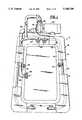
- FIG. 1is a perspective view of a whirlpool bath with parts broken away to show the piping system, pump and flow-regulating control embodying this invention
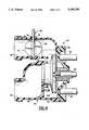
- FIG. 2is a sectional view through the pump shown in FIG. 1 showing the flow-regulating valve means embodying this invention in open position;
- FIG. 3is a fragmentary view corresponding to FIG. 2 showing the valve means in closed position
- FIG. 4is a sectional view corresponding to FIG. 2 showing a modification of the invention
- FIG. 5is a fragmentary view, partly in section, showing a modification of the invention for operating the flow regulating valve.
- FIG. 1there is shown an illustrative application of this invention to a conventional whirlpool bath 10 having the usual tub 12 provided with side walls 14, a flat extended rim or lip 16, and enclosure walls 18 depending from the outer periphery of the rim.
- the tub 12has nozzles 20 mounted in the side walls 14 to direct streams or jets of water into the tub.
- the nozzles 20are supplied with water through supply piping 22 connected to the outlet 24 of a centrifugal pump 26.
- the systemalso includes a suction head 28 in the tub 12 connected to a return flow pipe 30 connected to the inlet 32 of the pump 26.
- the pump 26usually is driven by an electric motor 34.
- the pump 26is substantially conventional in that it has a housing 36 including an integral housing body 38 defining the pump inlet 32, in the form of an exteriorly threaded tubular stub or neck for connection of the return flow pipe 30 thereto, and the outlet 24, also in the form of an exteriorly threaded tubular stub or neck for connection of the piping 22 thereto.
- the housing body 38also defines a rotor or impeller chamber 40 having a side opening 42 thereto for reception of an impeller 44 secured to the end of a driving shaft 46 which sealingly extends from the motor 34 through a detachable housing cover 48 for the opening.
- the cover 48is secured to the body 38 by bolts 50 and is supported on one end of the motor 34 by supports 52.
- the body 38is shown as one integral part, it may be made in the form of two or more appropriately connected parts.
- the pump outlet 24conventionally is circular and according to this invention there is rotatably mounted therein a flow-regulating valve in the form of a butterfly valve 54 comprising a valve disc 56 fastened by a pin 57 on an operating shaft 58 having a stub end 60 journalled in a socket 62 in the wall of the outlet and the other end 64 extended oppositely through that wall to the exterior thereof. Where it extends through the wall, the shaft 58 is sealed so as to prevent leakage to the exterior. While such a seal can be effected by any number of ways, the valve disc 56 is circularly enlarged, as at 66, adjacent a flat 68 on the wall, the enlargement provided with an annular groove 70 facing that flat and an O-ring 72 is mounted in that groove for engagement with the flat.
- the valve 54may be moved, i.e. rotated, continuously in either direction by the shaft 58 to adjust the position of the valve to regulate flow from the pump 26.
- the outer end 64 of the shaft 58has one end of a flexible cable 74, similar to a speedometer cable, attached thereto for rotating the valve disc 56.
- the attachmentcan be made by fixing the cable end in a socket in the shaft end with a set screw, as shown.
- the other end of the cable 74extends to a position beneath the lip or rim 16 of the tub 12 where it is fastened to the stem (not shown) of a knob 76.
- the knob 76is on the upper side of the rim 16 in a position to be readily accessible to an occupant of the tub 12 without the necessity of getting out of the tub or standing up therein.
- the stemis rotatably mounted in the lip 16 so that rotation of the knob 76 rotates the valve disc 56 in either direction to adjust the flow to a desired rate.
- the foregoing constructionnot only is more compact and space saving but also is less expensive than a separate flow regulating valve installed in piping downstream of the pump. Not only is expense lessened but also the foregoing construction is labor saving as contrasted to the installation of a flow regulating valve in downstream piping.
- FIG. 4there is shown a modification of the invention wherein the pump outlet 24 is substantially parallel to the pump inlet 32 instead of extending generally at right angles thereto as shown in FIG. 3.
- the flexible cable 74While the flexible cable 74, comparable to a speedometer cable, operates satisfactorily to operate the valve 54 with the knob 76, also it has been found that the cable can be replaced satisfactorily with a flexible rod (not shown) made of polycarbonate. In operation, the rod functions substantially the same as a flexible cable.
- valve 54also can be operated electrically, as shown in FIG. 5, wherein the outer end 64 of the valve shaft 58 is connected to the output shaft 78 of an electric reduction-geared motor 80 by a short flexible cable or rod 82.
- the motor 80may be located in a housing 84 secured, as by straps 86, to the pump drive motor 34 to provide a unitary package which includes the pump 26, drive motor 34, flow regulating valve 54, valve motor 80 and electric motor control switches 88 in the housing.
- the packageis powered by an electric cable 90 extending from the switches 88 out of the housing 84 to any appropriate electric power source, e.g. 110 v AC.
- Electric power cables 92, 94also extend from the switches 88, respectively, out of the housing 84 to the pump motor 34 and within the housing to the valve motor 80.
- the switches 88are controlled by a push button 96 connected to the switches and which may be located conveniently in the lip 16 of the tub 12 where it is readily accessible to an occupant of the tub.
- the button 96When the button 96 is in raised position, the valve motor 80 is disconnected from the cable 90, i.e. from the power source, but in depressed position the motor 80 is connected to the power source.
- the button 96is first pressed down the pump motor 34 is connected to the power cable 90, i.e. the power source, and when released that connection is maintained.
- the pump motor 34is disconnected from the power cable 90.
- the switches 88, push button 96 and its connection to the switchesmay be of any suitable type, in actual practice air-operated switches have been used and the push button includes a bellows, or equivalent air-pressurizing device, connected to the switches by a tube.
- the push button 96may be pressed. This operates the switches 88 to start both the pump motor 34 and the valve motor 80.
- both motors 34 and 80continue to run and the motor 80 slowly rotates the valve 54 in one direction to any selected adjusted position to regulate the flow as desired.
- the switches 88continue to operate the pump motor 34 but stop the valve motor 80 and the latter retains the valve 54 in its attained desired flow-regulating position.
- the switches 88stop the pump motor 34 and flow from the pump 26. Then when the button 96 is again released the valve 54 is left substantially in its adjusted flow regulating position because the period of depression of the button is so brief that the motor 80 barely moves the valve, if at all. The operation may then be repeated.
Landscapes
- Health & Medical Sciences (AREA)
- Public Health (AREA)
- Engineering & Computer Science (AREA)
- Life Sciences & Earth Sciences (AREA)
- Physical Education & Sports Medicine (AREA)
- Rehabilitation Therapy (AREA)
- Pain & Pain Management (AREA)
- Animal Behavior & Ethology (AREA)
- General Health & Medical Sciences (AREA)
- Veterinary Medicine (AREA)
- Epidemiology (AREA)
- Mechanical Engineering (AREA)
- General Engineering & Computer Science (AREA)
- Percussion Or Vibration Massage (AREA)
- Structures Of Non-Positive Displacement Pumps (AREA)
Abstract
Description
Claims (10)
Priority Applications (1)
| Application Number | Priority Date | Filing Date | Title |
|---|---|---|---|
| US08/172,382US5408708A (en) | 1993-10-29 | 1993-12-23 | Flow-control for a pump |
Applications Claiming Priority (2)
| Application Number | Priority Date | Filing Date | Title |
|---|---|---|---|
| US60423793A | 1993-10-29 | 1993-10-29 | |
| US08/172,382US5408708A (en) | 1993-10-29 | 1993-12-23 | Flow-control for a pump |
Related Parent Applications (1)
| Application Number | Title | Priority Date | Filing Date |
|---|---|---|---|
| US60423793ADivision | 1993-10-29 | 1993-10-29 |
Publications (1)
| Publication Number | Publication Date |
|---|---|
| US5408708Atrue US5408708A (en) | 1995-04-25 |
Family
ID=24418779
Family Applications (1)
| Application Number | Title | Priority Date | Filing Date |
|---|---|---|---|
| US08/172,382Expired - LifetimeUS5408708A (en) | 1993-10-29 | 1993-12-23 | Flow-control for a pump |
Country Status (1)
| Country | Link |
|---|---|
| US (1) | US5408708A (en) |
Cited By (17)
| Publication number | Priority date | Publication date | Assignee | Title |
|---|---|---|---|---|
| US5681025A (en)* | 1995-01-20 | 1997-10-28 | Kohler Co. | Motor operated butterfly valve with a multi-function seal |
| US6056506A (en)* | 1998-09-23 | 2000-05-02 | Emerson Electric Co. | Pump assembly for jetted tub |
| US6102657A (en)* | 1998-11-09 | 2000-08-15 | Hydrabaths, Inc. | Self-draining centrifugal pump having an improved inlet |
| US6155790A (en)* | 1998-06-01 | 2000-12-05 | Neles Controls Oy | Method and equipment for controlling a pipe network |
| US20060218715A1 (en)* | 2005-04-04 | 2006-10-05 | Gardenier W J | Valve system for a spa and a spa incorporating same |
| US20060275162A1 (en)* | 2005-05-20 | 2006-12-07 | Mayleben Philip A | Pump with combined floating wear ring and liquid director |
| US20080210309A1 (en)* | 2007-03-01 | 2008-09-04 | Randy Tan | Diverter valve |
| US20100031435A1 (en)* | 2008-08-06 | 2010-02-11 | Guy Lemire | Bypass system to control liquid volume |
| US20130011250A1 (en)* | 2010-02-16 | 2013-01-10 | Pierburg Pump Technology Gmbh | Mechanical coolant pump |
| US20170037856A1 (en)* | 2015-08-03 | 2017-02-09 | Parker-Hannifin Corporation | Integral pump pressure relief valve |
| US9775772B2 (en) | 2015-03-03 | 2017-10-03 | Kohler Co. | Whirlpool bathtub and purging system |
| US9979182B2 (en) | 2014-02-24 | 2018-05-22 | Intex Marketing Ltd. | Wave-making mechanism |
| US10960282B2 (en) | 2017-01-11 | 2021-03-30 | Intex Marketing Ltd. | Pool with an annular lane |
| US20210129002A1 (en) | 2019-11-01 | 2021-05-06 | Intex Industries Xiamen Co. Ltd. | Attachment structure for a swimming machine |
| US11522326B2 (en) | 2020-01-29 | 2022-12-06 | Balboa Water Group, Llc | Whirlpool bath controller with intelligent load control to reduce power requirements |
| US11583743B2 (en) | 2017-06-22 | 2023-02-21 | Intex Marketing Ltd. | Adjustable hanging assembly for flow generating device |
| US11959494B2 (en) | 2020-11-04 | 2024-04-16 | Gecko Alliance Group Inc. | Water-cooled pump assembly for bathing unit system and pump assembly for bathing unit system with mounting brackets |
Citations (11)
| Publication number | Priority date | Publication date | Assignee | Title |
|---|---|---|---|---|
| US1482405A (en)* | 1920-11-26 | 1924-02-05 | Moody Lewis Ferry | Operating mechanism for hydraulic turbines |
| US3396412A (en)* | 1965-07-02 | 1968-08-13 | Lawrence R. Francom | Bathtub |
| US3625628A (en)* | 1970-08-03 | 1971-12-07 | Carrier Corp | Capacity control operating mechanism for centrifugal compressor |
| US3635580A (en)* | 1970-02-26 | 1972-01-18 | Westinghouse Electric Corp | Centrifugal refrigerant gas compressor capacity control |
| US3698832A (en)* | 1970-06-18 | 1972-10-17 | Carl Price | Pump impeller housing with integral flow regulator |
| DE3408217A1 (en)* | 1984-03-07 | 1985-09-12 | Hugo Lahme GmbH, 5828 Ennepetal | Bath tub with a circulation unit, especially a whirlpool or bubbling bath tub |
| US4586204A (en)* | 1984-09-24 | 1986-05-06 | Daniels Phillip D | Recirculating bathtub |
| US4780917A (en)* | 1987-01-05 | 1988-11-01 | Hancock James W | Spa construction with integrated spa side and inside control system |
| US4844333A (en)* | 1988-04-08 | 1989-07-04 | Tridelta Industries, Inc. | Spa side control unit |
| DE3820350A1 (en)* | 1988-06-15 | 1989-12-21 | Keramag Keramische Werke Ag | Device for circulating water in sanitary installations |
| WO1990001917A1 (en)* | 1988-08-16 | 1990-03-08 | Gustavsberg Industri Ab | A pump arrangement intended for whirlpool baths and jacuzzi baths |
- 1993
- 1993-12-23USUS08/172,382patent/US5408708A/ennot_activeExpired - Lifetime
Patent Citations (11)
| Publication number | Priority date | Publication date | Assignee | Title |
|---|---|---|---|---|
| US1482405A (en)* | 1920-11-26 | 1924-02-05 | Moody Lewis Ferry | Operating mechanism for hydraulic turbines |
| US3396412A (en)* | 1965-07-02 | 1968-08-13 | Lawrence R. Francom | Bathtub |
| US3635580A (en)* | 1970-02-26 | 1972-01-18 | Westinghouse Electric Corp | Centrifugal refrigerant gas compressor capacity control |
| US3698832A (en)* | 1970-06-18 | 1972-10-17 | Carl Price | Pump impeller housing with integral flow regulator |
| US3625628A (en)* | 1970-08-03 | 1971-12-07 | Carrier Corp | Capacity control operating mechanism for centrifugal compressor |
| DE3408217A1 (en)* | 1984-03-07 | 1985-09-12 | Hugo Lahme GmbH, 5828 Ennepetal | Bath tub with a circulation unit, especially a whirlpool or bubbling bath tub |
| US4586204A (en)* | 1984-09-24 | 1986-05-06 | Daniels Phillip D | Recirculating bathtub |
| US4780917A (en)* | 1987-01-05 | 1988-11-01 | Hancock James W | Spa construction with integrated spa side and inside control system |
| US4844333A (en)* | 1988-04-08 | 1989-07-04 | Tridelta Industries, Inc. | Spa side control unit |
| DE3820350A1 (en)* | 1988-06-15 | 1989-12-21 | Keramag Keramische Werke Ag | Device for circulating water in sanitary installations |
| WO1990001917A1 (en)* | 1988-08-16 | 1990-03-08 | Gustavsberg Industri Ab | A pump arrangement intended for whirlpool baths and jacuzzi baths |
Cited By (26)
| Publication number | Priority date | Publication date | Assignee | Title |
|---|---|---|---|---|
| US5681025A (en)* | 1995-01-20 | 1997-10-28 | Kohler Co. | Motor operated butterfly valve with a multi-function seal |
| US6155790A (en)* | 1998-06-01 | 2000-12-05 | Neles Controls Oy | Method and equipment for controlling a pipe network |
| US6056506A (en)* | 1998-09-23 | 2000-05-02 | Emerson Electric Co. | Pump assembly for jetted tub |
| US6102657A (en)* | 1998-11-09 | 2000-08-15 | Hydrabaths, Inc. | Self-draining centrifugal pump having an improved inlet |
| US20060218715A1 (en)* | 2005-04-04 | 2006-10-05 | Gardenier W J | Valve system for a spa and a spa incorporating same |
| US20080189846A1 (en)* | 2005-04-04 | 2008-08-14 | Gardenier W John | Diverter Valve System for a Spa and a Spa Incorporating Same |
| US7544041B2 (en) | 2005-05-20 | 2009-06-09 | Wayne/Scott Fetzer Company | Pump with combined floating wear ring and liquid director |
| US20060275162A1 (en)* | 2005-05-20 | 2006-12-07 | Mayleben Philip A | Pump with combined floating wear ring and liquid director |
| US8910662B2 (en) | 2007-03-01 | 2014-12-16 | Zodiac Pool Systems, Inc. | Diverter valve |
| US7849877B2 (en) | 2007-03-01 | 2010-12-14 | Zodiac Pool Systems, Inc. | Diverter valve |
| US20080210309A1 (en)* | 2007-03-01 | 2008-09-04 | Randy Tan | Diverter valve |
| US20100031435A1 (en)* | 2008-08-06 | 2010-02-11 | Guy Lemire | Bypass system to control liquid volume |
| US20130011250A1 (en)* | 2010-02-16 | 2013-01-10 | Pierburg Pump Technology Gmbh | Mechanical coolant pump |
| US10193329B2 (en) | 2014-02-24 | 2019-01-29 | Intex Marketing Ltd. | Wave-making mechanism |
| US9979182B2 (en) | 2014-02-24 | 2018-05-22 | Intex Marketing Ltd. | Wave-making mechanism |
| US9775772B2 (en) | 2015-03-03 | 2017-10-03 | Kohler Co. | Whirlpool bathtub and purging system |
| US10071018B2 (en) | 2015-03-03 | 2018-09-11 | Kohler Co. | Whirlpool bathtub and purging system |
| US20170037856A1 (en)* | 2015-08-03 | 2017-02-09 | Parker-Hannifin Corporation | Integral pump pressure relief valve |
| US10513343B2 (en)* | 2015-08-03 | 2019-12-24 | Parker-Hannifin Corporation | Integral pump pressure relief valve |
| US10960282B2 (en) | 2017-01-11 | 2021-03-30 | Intex Marketing Ltd. | Pool with an annular lane |
| US11583743B2 (en) | 2017-06-22 | 2023-02-21 | Intex Marketing Ltd. | Adjustable hanging assembly for flow generating device |
| US20210129002A1 (en) | 2019-11-01 | 2021-05-06 | Intex Industries Xiamen Co. Ltd. | Attachment structure for a swimming machine |
| US11890522B2 (en) | 2019-11-01 | 2024-02-06 | Intex Marketing Ltd. | Attachment structure for a swimming machine |
| US11522326B2 (en) | 2020-01-29 | 2022-12-06 | Balboa Water Group, Llc | Whirlpool bath controller with intelligent load control to reduce power requirements |
| US11959494B2 (en) | 2020-11-04 | 2024-04-16 | Gecko Alliance Group Inc. | Water-cooled pump assembly for bathing unit system and pump assembly for bathing unit system with mounting brackets |
| US12410817B2 (en) | 2020-11-04 | 2025-09-09 | Gecko Alliance Group Inc. | Water-cooled pump assembly for bathing unit system and pump assembly for bathing unit system with mounting brackets |
Similar Documents
| Publication | Publication Date | Title |
|---|---|---|
| US5408708A (en) | Flow-control for a pump | |
| US5056168A (en) | Whirlpool bathtub | |
| US4841590A (en) | Water powered rotating shower brush | |
| US5983416A (en) | Electrically powdered spa jet unit | |
| US5742954A (en) | Electrically powered spa jet unit | |
| US6009574A (en) | Method and apparatus for providing a pulsed water massage | |
| US4432355A (en) | Hydromechanical massaging device | |
| US3846848A (en) | Control assembly for bathtub hydrotherapy unit | |
| ATE128855T1 (en) | WHIRLPOOL BATHTUB WITH DEVICES FOR GENERATING WATER AND/OR AIR JETS. | |
| US11359743B2 (en) | Electric water diverter | |
| US4689839A (en) | Tap water powered hydrotherapy method and apparatus | |
| US5634888A (en) | Hand held tap water powered water discharge apparatus | |
| US4823413A (en) | Combined pneumatic switch and air control for use in whirpool baths | |
| US4248570A (en) | Air blower for spas or the like | |
| JPH04219157A (en) | Shower device | |
| NL8802541A (en) | Agitating pump system fitted to conventional bath - draws water through bath wall, mixes with air bubbles and re-injects mixt. into bath water | |
| GB2075831A (en) | Shower mixers | |
| KR100233751B1 (en) | The apparatus for opening and shutting the cover in the hot house | |
| JPH0523231Y2 (en) | ||
| KR200268339Y1 (en) | Showering apparatus having shower-head mounted with water temperature and/or water flowing amount controller | |
| GB2141625A (en) | Shower installation including water pump | |
| KR200178008Y1 (en) | Air bed control box | |
| US4788725A (en) | Spa with slide valve | |
| KR910003546Y1 (en) | Fluid flow control apparatus for centrifugal pump | |
| JPH0732610Y2 (en) | Structure of manual stopcock for electrically controlled faucet |
Legal Events
| Date | Code | Title | Description |
|---|---|---|---|
| AS | Assignment | Owner name:VICO PRODUCTS MANUFACTURING CO., INC. Free format text:ASSIGNMENT OF ASSIGNORS INTEREST;ASSIGNOR:MATHIS, CLEO D.;REEL/FRAME:007156/0080 Effective date:19940926 | |
| FPAY | Fee payment | Year of fee payment:4 | |
| AS | Assignment | Owner name:STA-RITE INDUSTRIES, INC., WISCONSIN Free format text:ASSIGNMENT OF ASSIGNORS INTEREST;ASSIGNOR:VICO PRODUCTS MANUFACTURING CO., INC.;REEL/FRAME:012721/0171 Effective date:20020228 | |
| FEPP | Fee payment procedure | Free format text:PETITION RELATED TO MAINTENANCE FEES FILED (ORIGINAL EVENT CODE: PMFP); ENTITY STATUS OF PATENT OWNER: LARGE ENTITY | |
| REMI | Maintenance fee reminder mailed | ||
| REIN | Reinstatement after maintenance fee payment confirmed | ||
| FP | Lapsed due to failure to pay maintenance fee | Effective date:20030425 | |
| FEPP | Fee payment procedure | Free format text:PETITION RELATED TO MAINTENANCE FEES GRANTED (ORIGINAL EVENT CODE: PMFG); ENTITY STATUS OF PATENT OWNER: LARGE ENTITY | |
| FPAY | Fee payment | Year of fee payment:8 | |
| SULP | Surcharge for late payment | ||
| PRDP | Patent reinstated due to the acceptance of a late maintenance fee | Effective date:20040105 | |
| STCF | Information on status: patent grant | Free format text:PATENTED CASE | |
| FEPP | Fee payment procedure | Free format text:PAT HOLDER NO LONGER CLAIMS SMALL ENTITY STATUS, ENTITY STATUS SET TO UNDISCOUNTED (ORIGINAL EVENT CODE: STOL); ENTITY STATUS OF PATENT OWNER: LARGE ENTITY | |
| REFU | Refund | Free format text:REFUND - PAYMENT OF MAINTENANCE FEE, 12TH YR, SMALL ENTITY (ORIGINAL EVENT CODE: R2553); ENTITY STATUS OF PATENT OWNER: LARGE ENTITY | |
| FPAY | Fee payment | Year of fee payment:12 | |
| SULP | Surcharge for late payment | Year of fee payment:11 | |
| AS | Assignment | Owner name:STA-RITE INDUSTRIES, LLC, WISCONSIN Free format text:CHANGE OF NAME;ASSIGNOR:STA-RITE INDUSTRIES, INC.;REEL/FRAME:021985/0634 Effective date:20031223 Owner name:G-G DISTRIBUTION AND DEVELOPMENT CO., INC., CALIFO Free format text:ASSIGNMENT OF ASSIGNORS INTEREST;ASSIGNOR:STA-RITE INDUSTRIES, LLC;REEL/FRAME:021985/0652 Effective date:20081215 | |
| AS | Assignment | Owner name:DYMAS FUNDING COMPANY, LLC, AS ADMINISTRATIVE AGEN Free format text:SECURITY AGREEMENT;ASSIGNOR:G-G DISTRIBUTION AND DEVELOPMENT CO., INC.;REEL/FRAME:022012/0493 Effective date:20081215 | |
| AS | Assignment | Owner name:PNC BANK, NATIONAL ASSOCIATION, PENNSYLVANIA Free format text:SECURITY AGREEMENT;ASSIGNORS:BALBOA WATER GROUP, INC.;BALBOA INSTRUMENTS, INC.;G-G DISTRIBUTION AND DEVELOPMENT CO., INC.;REEL/FRAME:023538/0406 Effective date:20091105 Owner name:PNC BANK, NATIONAL ASSOCIATION,PENNSYLVANIA Free format text:SECURITY AGREEMENT;ASSIGNORS:BALBOA WATER GROUP, INC.;BALBOA INSTRUMENTS, INC.;G-G DISTRIBUTION AND DEVELOPMENT CO., INC.;REEL/FRAME:023538/0406 Effective date:20091105 | |
| FEPP | Fee payment procedure | Free format text:PAYER NUMBER DE-ASSIGNED (ORIGINAL EVENT CODE: RMPN); ENTITY STATUS OF PATENT OWNER: LARGE ENTITY Free format text:PAYOR NUMBER ASSIGNED (ORIGINAL EVENT CODE: ASPN); ENTITY STATUS OF PATENT OWNER: LARGE ENTITY | |
| AS | Assignment | Owner name:BALBOA WATER GROUP, INC., CALIFORNIA Free format text:ASSIGNMENT OF ASSIGNORS INTEREST;ASSIGNOR:G-G DISTRIBUTION AND DEVELOPMENT CO., INC.;REEL/FRAME:030963/0703 Effective date:20130731 | |
| AS | Assignment | Owner name:BMO HARRIS BANK N.A., AS ADMINISTRATIVE AGENT, ILLINOIS Free format text:PATENT SECURITY AGREEMENT;ASSIGNOR:BALBOA WATER GROUP, LLC;REEL/FRAME:051906/0375 Effective date:20151117 | |
| AS | Assignment | Owner name:BALBOA INSTRUMENTS, INC., CALIFORNIA Free format text:RELEASE BY SECURED PARTY;ASSIGNOR:PNC BANK, NATIONAL ASSOCIATION;REEL/FRAME:052918/0717 Effective date:20151117 Owner name:G-G DISTRIBUTION AND DEVELOPMENT CO., INC., CALIFORNIA Free format text:RELEASE BY SECURED PARTY;ASSIGNOR:PNC BANK, NATIONAL ASSOCIATION;REEL/FRAME:052918/0717 Effective date:20151117 Owner name:BALBOA WATER GROUP, LLC, CALIFORNIA Free format text:RELEASE BY SECURED PARTY;ASSIGNOR:PNC BANK, NATIONAL ASSOCIATION;REEL/FRAME:052918/0717 Effective date:20151117 Owner name:SPA & BATH HOLDINGS, INC., CALIFORNIA Free format text:RELEASE BY SECURED PARTY;ASSIGNOR:PNC BANK, NATIONAL ASSOCIATION;REEL/FRAME:052918/0717 Effective date:20151117 Owner name:BALBOA WATER GROUP, INC., CALIFORNIA Free format text:RELEASE BY SECURED PARTY;ASSIGNOR:PNC BANK, NATIONAL ASSOCIATION;REEL/FRAME:052918/0717 Effective date:20151117 | |
| AS | Assignment | Owner name:G-G DISTRIBUTION AND DEVELOPMENT CO., INC., CALIFORNIA Free format text:RELEASE BY SECURED PARTY;ASSIGNOR:DYMAS FUNDING COMPANY, LLC;REEL/FRAME:052197/0760 Effective date:20091101 | |
| AS | Assignment | Owner name:BALBOA WATER GROUP, LLC, CALIFORNIA Free format text:RELEASE BY SECURED PARTY;ASSIGNOR:BMO HARRIS BANK, N.A.;REEL/FRAME:054344/0627 Effective date:20201106 | |
| AS | Assignment | Owner name:BALBOA WATER GROUP, LLC, CALIFORNIA Free format text:CORRECTIVE ASSIGNMENT TO CORRECT THE PROPERTY NUMBER 8191183 PREVIOUSLY RECORDED AT REEL: 054344 FRAME: 0637. ASSIGNOR(S) HEREBY CONFIRMS THE RELEASE OF SECURITY INTEREST;ASSIGNOR:BMO HARRIS BANK, N.A.;REEL/FRAME:057144/0919 Effective date:20201106 |