US5408535A - Video test strip reader and method for evaluating test strips - Google Patents
Video test strip reader and method for evaluating test stripsDownload PDFInfo
- Publication number
- US5408535A US5408535AUS08/117,782US11778293AUS5408535AUS 5408535 AUS5408535 AUS 5408535AUS 11778293 AUS11778293 AUS 11778293AUS 5408535 AUS5408535 AUS 5408535A
- Authority
- US
- United States
- Prior art keywords
- test
- test strip
- image
- processor
- video
- Prior art date
- Legal status (The legal status is an assumption and is not a legal conclusion. Google has not performed a legal analysis and makes no representation as to the accuracy of the status listed.)
- Expired - Lifetime
Links
- 238000012360testing methodMethods0.000titleclaimsabstractdescription450
- 238000000034methodMethods0.000titleclaimsdescription31
- 239000000470constituentSubstances0.000claimsabstractdescription23
- 239000003153chemical reaction reagentSubstances0.000claimsabstractdescription19
- 230000007723transport mechanismEffects0.000claimsdescription34
- 238000005286illuminationMethods0.000claimsdescription16
- 230000007246mechanismEffects0.000claimsdescription15
- 239000002699waste materialSubstances0.000claimsdescription11
- 238000004458analytical methodMethods0.000claimsdescription9
- 230000032258transportEffects0.000claimsdescription7
- 238000001514detection methodMethods0.000claimsdescription5
- 238000003384imaging methodMethods0.000claimsdescription5
- 230000003287optical effectEffects0.000claimsdescription5
- 230000011664signalingEffects0.000claimsdescription3
- 230000001360synchronised effectEffects0.000claimsdescription3
- 230000003760hair shineEffects0.000claims2
- 238000000151depositionMethods0.000claims1
- 230000005484gravityEffects0.000abstractdescription2
- 239000011159matrix materialSubstances0.000description8
- 238000011534incubationMethods0.000description7
- 230000033001locomotionEffects0.000description7
- 230000000007visual effectEffects0.000description7
- 238000005259measurementMethods0.000description6
- BPYKTIZUTYGOLE-IFADSCNNSA-NBilirubinChemical compoundN1C(=O)C(C)=C(C=C)\C1=C\C1=C(C)C(CCC(O)=O)=C(CC2=C(C(C)=C(\C=C/3C(=C(C=C)C(=O)N\3)C)N2)CCC(O)=O)N1BPYKTIZUTYGOLE-IFADSCNNSA-N0.000description5
- 230000008859changeEffects0.000description5
- 239000007788liquidSubstances0.000description5
- 210000002700urineAnatomy0.000description4
- 238000010586diagramMethods0.000description3
- 238000005375photometryMethods0.000description3
- 238000001228spectrumMethods0.000description3
- 210000004369bloodAnatomy0.000description2
- 239000008280bloodSubstances0.000description2
- 210000000601blood cellAnatomy0.000description2
- 230000015556catabolic processEffects0.000description2
- 230000008878couplingEffects0.000description2
- 238000010168coupling processMethods0.000description2
- 238000005859coupling reactionMethods0.000description2
- 238000006731degradation reactionMethods0.000description2
- 230000000593degrading effectEffects0.000description2
- BXFFHSIDQOFMLE-UHFFFAOYSA-Nindoxyl sulfateChemical compoundC1=CC=C2C(OS(=O)(=O)O)=CNC2=C1BXFFHSIDQOFMLE-UHFFFAOYSA-N0.000description2
- 230000004044responseEffects0.000description2
- 238000012935AveragingMethods0.000description1
- 230000002411adverseEffects0.000description1
- 239000012491analyteSubstances0.000description1
- 238000003491arrayMethods0.000description1
- 239000003086colorantSubstances0.000description1
- 238000010276constructionMethods0.000description1
- 238000012937correctionMethods0.000description1
- 230000001351cycling effectEffects0.000description1
- 238000011161developmentMethods0.000description1
- 201000010099diseaseDiseases0.000description1
- 208000037265diseases, disorders, signs and symptomsDiseases0.000description1
- 238000003708edge detectionMethods0.000description1
- 239000000835fiberSubstances0.000description1
- 230000006870functionEffects0.000description1
- 230000005802health problemEffects0.000description1
- 230000036039immunityEffects0.000description1
- 238000002347injectionMethods0.000description1
- 239000007924injectionSubstances0.000description1
- 238000002372labellingMethods0.000description1
- 239000000463materialSubstances0.000description1
- 238000012986modificationMethods0.000description1
- 230000004048modificationEffects0.000description1
- 238000000926separation methodMethods0.000description1
- 230000003595spectral effectEffects0.000description1
Images


Classifications
- G—PHYSICS
- G01—MEASURING; TESTING
- G01N—INVESTIGATING OR ANALYSING MATERIALS BY DETERMINING THEIR CHEMICAL OR PHYSICAL PROPERTIES
- G01N21/00—Investigating or analysing materials by the use of optical means, i.e. using sub-millimetre waves, infrared, visible or ultraviolet light
- G01N21/84—Systems specially adapted for particular applications
- G01N21/8483—Investigating reagent band
- G—PHYSICS
- G01—MEASURING; TESTING
- G01N—INVESTIGATING OR ANALYSING MATERIALS BY DETERMINING THEIR CHEMICAL OR PHYSICAL PROPERTIES
- G01N21/00—Investigating or analysing materials by the use of optical means, i.e. using sub-millimetre waves, infrared, visible or ultraviolet light
- G01N21/17—Systems in which incident light is modified in accordance with the properties of the material investigated
- G01N2021/1765—Method using an image detector and processing of image signal
- G01N2021/177—Detector of the video camera type
- G—PHYSICS
- G01—MEASURING; TESTING
- G01N—INVESTIGATING OR ANALYSING MATERIALS BY DETERMINING THEIR CHEMICAL OR PHYSICAL PROPERTIES
- G01N35/00—Automatic analysis not limited to methods or materials provided for in any single one of groups G01N1/00 - G01N33/00; Handling materials therefor
- G01N35/00029—Automatic analysis not limited to methods or materials provided for in any single one of groups G01N1/00 - G01N33/00; Handling materials therefor provided with flat sample substrates, e.g. slides
- G01N2035/00099—Characterised by type of test elements
- G01N2035/00108—Test strips, e.g. paper
- Y—GENERAL TAGGING OF NEW TECHNOLOGICAL DEVELOPMENTS; GENERAL TAGGING OF CROSS-SECTIONAL TECHNOLOGIES SPANNING OVER SEVERAL SECTIONS OF THE IPC; TECHNICAL SUBJECTS COVERED BY FORMER USPC CROSS-REFERENCE ART COLLECTIONS [XRACs] AND DIGESTS
- Y02—TECHNOLOGIES OR APPLICATIONS FOR MITIGATION OR ADAPTATION AGAINST CLIMATE CHANGE
- Y02A—TECHNOLOGIES FOR ADAPTATION TO CLIMATE CHANGE
- Y02A90/00—Technologies having an indirect contribution to adaptation to climate change
- Y02A90/10—Information and communication technologies [ICT] supporting adaptation to climate change, e.g. for weather forecasting or climate simulation
- Y—GENERAL TAGGING OF NEW TECHNOLOGICAL DEVELOPMENTS; GENERAL TAGGING OF CROSS-SECTIONAL TECHNOLOGIES SPANNING OVER SEVERAL SECTIONS OF THE IPC; TECHNICAL SUBJECTS COVERED BY FORMER USPC CROSS-REFERENCE ART COLLECTIONS [XRACs] AND DIGESTS
- Y10—TECHNICAL SUBJECTS COVERED BY FORMER USPC
- Y10T—TECHNICAL SUBJECTS COVERED BY FORMER US CLASSIFICATION
- Y10T436/00—Chemistry: analytical and immunological testing
- Y10T436/11—Automated chemical analysis
Definitions
- the present inventiongenerally relates to the field of clinical chemistry. More particularly, the present invention relates to a visual imaging system that analyzes the color change associated with one or more test areas on a test strip following contact thereof with a liquid specimen, such as urine or blood.
- Reagent test stripsare widely used in the field of clinical chemistry.
- a test stripusually has one or more test areas, and each test area is capable of undergoing a color change in response to contact with a liquid specimen.
- the liquid specimenusually contains one or more constituents or properties of interest. The presence and concentrations of these constituents of interest in the specimen are determinable by an analysis of the color changes undergone by the test strip. Usually, this analysis involves a color comparison between the test area or test pad and a color standard or scale. In this way, reagent test strips assist physicians in diagnosing the existence of diseases and other health problems.
- strip reading instrumentsexist that employ reflectance photometry for reading test strip color changes. These instruments accurately determine the color change of a test strip within a limited wavelength range or bandwidth but sometimes fail to measure minute color inconsistencies outside the limited bandwidth. For example, such an instrument can fail to detect traces of blood within a urine specimen on a MULTISTIX® reagent strip of the type sold by Miles Inc., Diagnostics Division, of Elkhart, Ind. 46515. After the urine specimen contacts the test pad of a MULTISTIX® reagent strip, intact blood cells appear as tiny green blotches on the yellow test area.
- the first commercially available strip reading instruments of this typewere effective but unable to adequately cope with the large numbers of specimens handled by clinical laboratories. These instruments require inserting a single test strip, reading the test strip and removing the test strip from the instrument before the instrument can analyze the next test strip. Moreover, with certain instruments the speed of operation is limited by the requirement of precise placement of the strip in the instrument.
- U.S. Pat. No. 5,055,261discloses a multiple-strip reading instrument utilizing reflectance photometry to read test strips. An operator sequentially places the test strips transversely in a loading area. A blotter arm orients the test strips on rails extending from the loading area to one or more reading stations employing read heads and then to a waste receptacle.
- This instrumentprovides for the reading of reagent strips with multiple test areas having varying incubation times.
- An indexing mechanism in timed relation with the blotter armincrementally advances the strips in spaced parallel relation a predetermined distance along the rails. After each incremental advance, each test strip dwells for a predetermined time period in its new position. Consequently, individual test strips sequentially advance to a reading position where, during the dwell period, certain test areas are read. Subsequently, the instrument advances the test strip to the next reading position where the instrument reads the other test areas on the test strip with longer incubation times.
- the instrument embodied in U.S. Pat. No. 5,143,694also transports test strips at a right angle to their longitudinal direction from a strip loading area, along a transport path under the read heads to a waste receptacle. In order to obtain accurate results, these instruments require that the test strips be read at the appropriate time.
- a common feature of these instrumentsis a visual and auditory prompt signalling the operator to dip a strip in the sample and place it in the loading area of the instrument.
- these promptsoccur at fixed time intervals, such as every 10 or 12 seconds.
- operators frequently fail to comply with the promptsby either not understanding or choosing to ignore the manufacturer's instruction about immersing the test strip when the tone is presented.
- This timing differential between the instrument prompt and when the operator actually dips the test stripcan cause a degradation of measurement results.
- forcing the user to dip and place strips as dictated by the instrumentadds pressure onto the operator and can lead to human error.
- the present inventionefficiently provides enhanced reagent test strip measurement results, improves test strip reading efficiency, eliminates the inflexibility associated with prior reagent test strip readers and reduces the potential for human error degrading test results.
- the present inventionaccomplishes this by utilizing a color video imager or camera aimed at a viewing field containing reagent test strips. Each test strip has test pads reacted with a specimen containing constituents of interest.
- the video imagerproduces an analog signal representing an image of the viewing field.
- An image handler coupled to the video imagerincludes a signal converter that converts or digitizes the analog signal into a digital signal representing the image. Alternatively, the video imager can include the signal converter such that the video imager provides a digital signal representing the image to the image handler.
- the image handierstores the image, represented by the digital signal, in the form of an array of pixels representing the image. Each pixel contains color information broken down into red, green or blue (RGB).
- a processor coupled to the image handleranalyzes the array of pixels, determines the location and orientation of a test strip and its test pads, measures the corresponding test areas or pads on the strip at the proper time and calculates the test results for the specimen.
- the present inventionimproves the efficiency of the strip reader by simultaneously analyzing and time tracking multiple test strips on the viewing field.
- the processor for the video strip readerdetects the placement and removal of a test strip on the viewing field.
- Test strip placementoccurs when an operator dips the test strip in a specimen and places the test strip on the viewing field.
- the processordetects the placement of a test strip onto the viewing field by detecting the test strip as having pixel values above a background threshold level.
- the processoralso detects the removal from the viewing field of an existing test strip when the previous pixel values corresponding to the test strip have fallen below the background threshold level. If the operator adds a new test strip, the processor locates the test pads for the test strip by analyzing the pixel array and finding the boundaries of the test strip.
- the processoralso tracks the amount of time that the test strip is on the viewing field. At the proper time, the processor analyzes the appropriate test areas or pads and calculates the test results, such as the concentrations of the constituents of interest.
- the video reader of the present inventioneliminates the potential degradation of measurement results due to human error, and, at the same time improves the efficiency of test strip reading.
- the operatoris not required to comply with timed prompts from the test strip reader to dip a test strip in a specimen and immediately place the test strip on the loading area.
- the operatorjust dips the test strip in a specimen and immediately places the test strip in the viewing field of the present invention, prompting the machine to time and analyze each strip placed in the viewing field.
- Strip reading efficiencyimproves because the video reader, can analyze multiple test strips simultaneously, and the operator is also not constrained by the time prompts of previous strip readers.
- a transport mechanismtransports test strips from a loading area into the viewing field and into a waste receptacle.
- the processor of the video test strip reader itself or a separate loading area sensordetects the placement of a test strip on the loading area. Upon the placement of the test strip on the loading area, the processor tracks the timing for the corresponding test strip.
- the placement of the test strip on the loading areatriggers the transport mechanism to move the test strip in the viewing field. After entering the viewing field, the test strip does not move until another test strip is placed in the loading area. At that time, the transport mechanism moves or indexes the test strip a fixed distance in the viewing field. The test strips in the viewing field will move the same fixed distance with each subsequent index of another test strip.
- the transport mechanismindexes multiple test strips in the viewing field and, thereby, maximizes the number of test strips in the viewing field and improves the efficiency of the test strip reader.
- the present inventionalso encompasses a test strip reader where the processor controls the movement of the transport mechanism according to the timing of the various test strips in the viewing field.
- the video test strip reader of the present inventionpermits enhanced test strip reading capabilities because of its video imaging capabilities.
- the present inventioncan utilize markings incorporated on each test strip to distinguish between individual test strips or between different types of test strips.
- the present inventioncan also utilize a color standard contained in the viewing field, providing an absolute reflectance standard for the processor.
- the present inventionhas a wavelength response similar to the human eye and uses the entire visual spectrum to view the viewing field.
- the video test strip readercan detect small spots or other color distortions on a test pad, such as the green spots representing intact blood cells in a urine specimen and the color distortion in a bilirubin test that signals a false positive bilirubin result.
- the present inventionis capable of measuring test strips whose format does not conform to that of a MULTISTIX® reagent strip.
- Certain immunodiagnostic stripsare constructed such that the presence of an analyte in the sample produces a narrow band of color across the width of the strip. The presence of multiple analytes would be indicated by the development of colored bands at different locations along the length of the strip.
- Certain other immunodiagnostic stripsmay consist of adjacent pads with no physical separation between them.
- the video test strip readercan locate each band of color, determine the physical extent of each color band and measure spectral reflectance within each color band.
- the present inventionprovides enhanced, efficient and flexible reading of different test strips while reducing the risk of human error.
- the present inventionaccomplishes this by utilizing a video imaging system to perform test strip measurement on test pads located by the processor.
- the video strip readeroperates similar to the human eye and provides enhanced detection because the entire visual spectrum is analyzed.
- the visual readercan simultaneously time and analyze multiple test strips, improving efficiency and flexibility. Flexibility is further improved because the timing for the present invention does not rely on the fixed mechanical structure of the test strip reader itself.
- FIG. 1shows an embodiment of the visual test strip reader in accordance with the present invention
- FIG. 2shows an alternative embodiment of the video test strip reader in accordance with the present invention
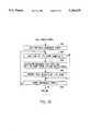
- FIG. 3shows an image of the viewing area with two strips and a color standard thereon
- FIG. 4is a flow chart diagram illustrating the operation of the video test strip reader in accordance with the present invention.
- FIGS. 5-10are flow chart diagrams detailing the individual operations illustrated in FIG. 4.
- the video reader 10provides enhanced measurement results, eliminates the inflexibility associated with prior reagent test strip readers and reduces the potential for human error degrading test results. Moreover, the video strip reader 10 improves the efficiency of the strip reader because the present invention can simultaneously locate, color analyze and time track multiple test strips on the viewing field.
- the video strip reader 10utilizes a color video imager 12 or camera that views a reading field 14 containing a reagent test strip 16.
- Each test strip 16has test pads 28 reacted with a specimen containing constituents of interest. The test pads 28 change color when reacted with a liquid specimen containing constituents of interest. By analyzing the color of a test pad 28 after one or more read times for the test pad 28 have expired, the concentration or presence of a constituent of interest can be determined as well as other measurable properties of the liquid specimen such as color or specific gravity.
- the video imager 12produces an analog signal representing a color image of the viewing field 14.
- An example of the video imager 12is a Model WAT-201 color video camera sold by Watec Co., Ltd.
- the present inventionalso encompasses using as the video imager a CID (charge injection device), a monochrome CCD camera having external color filters or a vidicon camera.
- An illumination source 13illuminates the viewing field 14.
- the illumination source 13should evenly illuminate the viewing field 14 in order for video imager 12 to accurately measure the color or reflectance of the various test pads 28.
- the illumination source 13is preferably a DC light source with a control feedback to minimize light fluctuations.
- This illumination source 13is shown in FIG. 1 as a fiber optic illumination ring connected to a stabilized source 15. Alternatively, a lamp positioned in place of illumination source 13 can be used.
- the video test strip reader 10 of FIG. 1is illustrated with a conventional personal computer 33.
- the personal computerincludes an image handler 18 conventionally coupled to the video imager 12.
- the image handler 18includes a signal converter 20 that converts or digitizes the analog signal from the video imager 12 into a digital signal representing the image.
- the image handler 18also stores the image represented by the digital signal in the form of a two-dimensional array or matrix of pixels.
- the image handler 18is a commercial frame-grabber board coupled to an I/O port of the personal computer 33.
- commercial frame-grabber boardsinclude a signal converter 20 for converting the analog signal from the video imager 12 to a digital signal.
- FIG. 1illustrates the image handler 18 as including the signal converter 20, but the signal converter 20 can be separate from the image handler 18.
- the image handler 18can be a MVPAT frame-grabber board sold by Matrox.
- the personal computer 33includes a processor 24 and storage memory 26.
- the processor 24then analyzes successive arrays of pixels to determine the placement of the test strip 16 on the viewing field 14 and, with a timing mechanism (not shown), keeps track of an elapsed time from the placement of the corresponding test strip 16 on the viewing field 14.
- the timing mechanism of the processor 24can include a system clock running at a known frequency. After the placement of a test strip 16 on the viewing field 14, the processor 24 determines the location and orientation of the test strip 16 and its test pads 28 from a current array of pixels.
- the processor 24measures the reflectance for that test area or test pad 28. When multiple read times are used, the previous step is repeated for each read time. The processor 24 then calculates the concentration of the constituents of interest in the specimen or other test results using the reflectance reference matrices and the reflectance values for those portions of the array of pixels representing the test pads 28. At this point, the test strip 16 is finished.
- the processor 24is conventionally coupled to a display 30 or a printing mechanism 32 for displaying the test results.
- the processor 24is also coupled to a storage memory 26 for storing analysis data, instructions and calculation results.
- the personal computer 33is an IBM AT personal computer with a 286 microprocessor or compatible shown with the display 30, the printing mechanism 32, a secondary storage 34, such as disk storage, and a keyboard 29.
- FIG. 2illustrates another video strip reader in accordance with the present invention, generally designated by the reference numeral 11.
- Video reader 11also includes a video imager 12, an image handler 19, a processor 25 and storage memory 27 that operate as the corresponding elements shown in FIG. 1, but the embodiment of FIG. 2 shows these elements as being together within a housing 35 of the video test strip reader 11.
- the housing 35prevents outside interference from adversely affecting test strip analysis.
- the processor 25can be a DSP (digital signal processor) on a dedicated board along with storage memory 27.
- the image handler 19can be a separate frame grabber board or a custom frame-grabber on the same or a different dedicated board. As stated above, the image handier 19 is described as including a signal converter 21.
- the signal converter 21can be a conventional video analog to digital converter.
- the processor 25, the image handler 19 and the storage memory 27can take the form of hard-wired circuitry.
- FIG. 2shows an illumination source 13 shining on the viewing field 14 with a test strip 16.
- the processor 25is also shown as being coupled to a secondary storage, a display 31, a printer 33, and a key pad 39.
- the video strip reader 11uses a transport mechanism 36 to transport the test strip 16 from a loading area 38 into the viewing field 14 and into a waste receptacle 40.
- the loading area 38is not shown as being in the viewing field 14 in FIG. 2, placement of the loading area 38 can be alternatively positioned within the viewing field 14.
- the test strip reader 11can detect the placement of a test strip 16 onto the viewing field 14 by utilizing the processor 25 to analyze a current pixel array representing an image of the viewing field 14.
- the processor 25Upon detecting the placement of a test strip 16 on the viewing field 14, the processor 25, which includes a known timing mechanism (not shown), keeps track of an elapsed time from the placement of the corresponding test strip 16 on the viewing field 14.
- the timing mechanism of the processor 25can include a system clock running at a known frequency.
- the processor 25detects the placement of the test strip 16 on the loading area in the viewing field 14, the processor 25 is coupled to and signals the transport mechanism 36 to transport the test strip 16. Additionally, the processor 25 can control the movement of the transport mechanism 36 according to the status of the various test strips 16 on the viewing field 14. For example, if all the test strips 16 are finished, the processor 25 can signal the transport mechanism 36 to transport the test strips 16 to the waste receptacle 40.
- a loading sensor 42detects the placement of the test strip 16 on the loading area 38 and signals the processor 25 that the operator has placed a new test strip 16 in the loading area 38.
- the loading area sensor 42couples to the processor 25 by a control line 43.
- the processor 25uses the timing mechanism to keep track of an elapsed time from the placement of the corresponding test strip 16 on the loading area 38 as described above.
- the loading area sensor 42can include an optical interrupter utilizing a modulated LED 44 and a synchronous photodetector 46.
- this same loading area sensor signalalso triggers the transport mechanism 36 to move the test strip 16 in the viewing field 14 either directly through a control line coupling the loading area sensor 42 to the transport mechanism 36 or indirectly through a control line coupling the processor 25 to the transport mechanism 36.
- the transport mechanism 36includes a motor control circuitry 49 that controls the operation of a motor 50.
- the motor control circuitry 49is coupled to the motor 50 and can vary widely in form depending on the embodiment.
- the motor control circuitry 49can be coupled directly to the loading area sensor 42, the processor 25 or both depending on the embodiment. If an embodiment utilizes processor 25 to determine the placement of a test strip 16 on the loading area and not a loading sensor, then the motor control circuitry 49 couples to the processor 25 through a control line. But if the loading area sensor 42 detects new strip placement as in FIG. 2, the motor control circuitry 49 can couple to the loading area sensor 42 through a control line 45 in order to receive loading area sensor signals.
- the motor control circuitry 49can alternatively couple to the processor 25 through a control line 47 to receive motor control signals from the processor 25 after the processor 25 receives a loading area sensor signal.
- FIG. 2shows both the processor 25 and the loading sensor 42 coupled to the motor control circuitry 25, so both can signal the motor control circuitry 49.
- the transport mechanism 36further includes the motor 50, a strip conveyor 48, a movement assembly 53, such as a conventional Geneva assembly 53, and a blotter arm 51.
- the motor 50provides the power to mechanically operate the transport mechanism 36.
- the motor 50is mechanically linked to the Geneva assembly 53.
- the Geneva assembly 53is mechanically linked in a timed relation to the strip conveyor 48 and the blotter arm 51 to coordinate the movement of both the strip conveyor 48 and the blotter arm 51 according to the characteristics of the Geneva assembly 53.
- the coordinated movement of the strip conveyor 48 and the blotter arm 51efficiently indexes the test strips 16 onto the strip conveyor 48 as described below.
- FIG. 2shows the blotter arm 51 on the loading area 38.
- the motor control circuitry 49receives a signal from either the processor 25 or the loading area sensor 42.
- the motor control circuitry 49activates motor 50 causing the blotter arm 51 to move the test strip 16 onto the strip conveyer 48.
- the test strip 16does not move on the strip conveyor 48 until another test strip is placed in the loading area 38.
- the blotter arm 51moves the next test strip onto the strip conveyor 48 while conveyor 48 moves the test strip 16 a fixed distance.
- Each test strip 16 in the viewing field 14will move the same fixed distance with each subsequent index of another test strip. This calibrated and intermittent movement permits the proper indexing of test strips and is accomplished with the Geneva assembly 53. Consequently, the transport mechanism 36 indexes multiple test strips 16 in the viewing field 14 and, thereby, maximizes the number of test strips 16 in the viewing field 14 and improves the efficiency of the video strip reader 11.
- FIG. 3shows an image 52 of the viewing field 14.
- the image 52is composed of a two-dimensional array of pixels representing the viewing field 14.
- the upper left hand comer of the image 52represents the origin of this two-dimensional array with coordinates (0,0) in pixels.
- the x-axis pixel coordinatesincrease by moving horizontally from left to right across the image 52 along a horizontal line of pixels, and the y-axis pixel coordinates increase vertically from top to bottom along a vertical column of pixels.
- Each pixelcontains color information broken down into red, green or blue (RGB).
- the processor 25analyzes the image 52 to determine the location and orientation of the test strip 16 and its test pads 28.
- the processor 25measures the reflectance for that portion of the two dimensional pixel array or image 52 representing that test area or test pad 28. This step is repeated for multiple read times. The processor 25 then calculates the concentration of the constituents of interest in the specimen or other test results.
- the present inventioncan utilize markings 54 incorporated on each test strip 16 to distinguish between individual test strips and different types of test strips.
- the present inventioncan evaluate the alphanumeric or bar code information and report the results for each specimen or patient, reducing the possibility of human recording error.
- the ability to distinguish between different types of test stripsenhances the flexibility of the present invention because the present invention can alter its analysis or timing to accommodate for the different type of test strip 16.
- the video strip reader of the present inventioncan also utilize a color standard 56 contained in the viewing field to ensure that the present invention accurately analyzes the test strips.
- FIG. 3illustrates a color standard 56 on the image 52 in the form of a color strip.
- an absolute reflectance standardis always present for the processor 25 when analyzing the image 52.
- the color standard 56permits continuous correction for illumination changes.
- the color standard 56can be located on the test strip itself.
- FIG. 4is a flow chart diagram of the overall operation of the embodiment illustrated in FIG. 1.
- step 100calibrates the reflectance for the video strip reader 10.
- the processor 24builds RGB reflectance reference matrices or calibration matrices for the viewing field 14 by reading the red, green and blue reflectance values for the viewing field 14.
- Step 102calculates a background threshold for reflectance from the blue reflectance reference matrix.
- the processor 24rejects any reflectance values below the background threshold as noise, but reflectance values above the background threshold can represent the presence of a test strip 16 on the viewing field 14.
- Step 104sets a loop in which processor 24 cycles through steps 106-128 about every two seconds when unfinished test strips are present on the viewing field 14.
- Step 106creates raw reflectance matrices for the red, green and blue colors (RGB) of the image 52 by grabbing the RGB image 52 three times and averaging the raw pixel signals to complete the raw RGB reflectance matrices.
- Step 108determines whether there are unfinished test strips on the viewing field 14. If not, the processor 24 proceeds to step 122 to detect any new test strips and classify any new test strips as "pending.”
- step 110the processor 24 performs step 110 by checking every test pad 28 on each unfinished test strip.
- Step 110calculates the RGB reflectance values for each test pad with a current read time.
- step 120checks if a new test strip is "pending.” If no new test strip is "pending,” the processor proceeds to step 122 to detect any new test strips and classify any new strips as “pending.” If a "pending" new test strip exists, step 124 finds the location for each test pad 28 by locating the four comers of each test pad 28 of a "pending” new test strip and releases the "pending" status of the new test strip.
- step 110After labeling any new test strips as "pending” or locating the test pads 28 for a previously “pending” test strip, the present invention checks all test strips to determine whether a test strip is finished.
- a test strip 16is finished when the read time or times for every test pad 28 on the test strip 16 has expired and the RGB reflectance values for every test pad 28 on the finished test strip was determined at step 110. If a test strip 16 is finished, step 126 reports the test results derived from the timed RGB reflectance values for that test strip 16. Finally, step 128 determines whether any unfinished strips remain. If so, the processor 24 cycles back to step 104, grabs a new set of RGB images, averages the raw pixel signals to construct another set of raw RGB reflectance matrices, and proceeds through the steps 106-128.
- step 130determines whether a predetermined amount of time has passed since a new test strip has been placed onto the viewing field 14. If the time limit has expired, the illustrative system stops, but if the time limit is not exceeded, the processor 24 continues cycling through steps 106-130 every two seconds.
- FIG. 5details how step 102 of FIG. 4 calculates the background threshold level for a background image in order to accomplish strip-edge detection of steps 122 and 124.
- step 200grabs the blue reflectance reference matrix of the background image created at step 100 of FIG. 4.
- step 202calculates the average blue reflectance value for the background image using the blue reflectance reference matrix as well as the standard deviation.
- Step 204determines the background threshold level with the equation:
- step 110 of FIG. 4checks every test pad on each unfinished test strip and calculates its RGB reflectance if the read time for the test pad has expired.
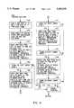
- FIG. 6details the operation of step 110 of FIG. 4.
- Step 300establishes an unfinished test strip loop based on the number of unfinished test strips.
- Step 302adds two seconds to the time counter for an I-th unfinished test strip within the unfinished test strip loop of step 300.
- Step 304establishes a test pad loop within the unfinished test strip loop based on the number of test pads for the I-th unfinished test strip.
- step 306determines whether the time counter or current time for the I-th unfinished test strip equals or exceeds the read time for the J-th test pad. If not, the processor 24 advances the test pad loop to the next test pad on the I-th unfinished test strip and proceeds back to step 306.
- step 306determines that the read time of the J-th test pad on the I-th test strip has expired, the processor 24 must calculate the RGB reflectance values for the J-th pad.
- step 308calculates an average raw RGB reflectance for the J-th test pad on the I-th test strip.
- step 310derives the average reflectance reference levels from the RGB reflectance reference matrices or calibration matrices of step 100. With the average reflectance reference levels and the average raw RGB reflectance corresponding to the J-th pad on the I-th strip, step 312 derives the RGB reflectance values for the J-th pad on the I-th strip.
- Step 314stores the RGB reflectance values for the J-th pad on the I-th strip. If more test pads exist on the I-th test strip, processor 24 advances to the next test strip and proceeds to step 306. But if the test pad loop finishes, the processor 24 advances to the next test strip and proceeds to step 302. When the unfinished test strip loop finishes, the processor returns to step 120 of FIG. 4.
- FIG. 7details step 122 of FIG. 4 for detecting the presence of a new test strip on the viewing field.
- Step 400begins by reading a predetermined low row from the raw blue reflectance matrix of the raw RGB reflectance matrices of step 106.
- Step 402establishes an existing test strip loop.
- step 404determines whether three consecutive pixels of the existing I-th test strip are below the background threshold level calculated in FIG. 5. If the three consecutive pixels of the existing I-th strip are below the background threshold level, then step 406 recognizes that the existing I-th test strip has been removed from the viewing field 14. But if the three consecutive pixels of the existing I-th test strip remain above the background threshold level, step 408 recognizes that the existing I-th test strip remains on the viewing field 14, and step 408 masks the pixels of the existing I-th test strip with the background threshold level.
- Step 412detects the presence of new test strips by checking from left to right on the low row for three consecutive pixels above the background threshold value (three consecutive pixels were chosen only to provide good "noise” immunity), signalling the edge of a new test strip on the viewing field 14. Step 412 sets the status of any new test strip as "pending” and returns the processor 24 to step 126 of FIG. 1.
- step 120the processor 24 determines that a new strip is "pending" from the previous cycle through the new strip detection mechanism of FIG. 7, step 124 locates the four comers of each pad of a new strip and releases the "pending" status for a new test strip.
- FIG. 8details an initial portion of step 124 in which processor 24 finds four boundary points for a "pending" new test strip.
- Step 500reads a high row (Yh) and a low row (Yl) from the raw blue reflectance matrix of step 106. On those high and low rows selected by step 500, step 502 masks pixels of existing test strips with the background level.
- Step 504finds the left upper edge boundary point, X1h, of the "pending" new test strip by checking the high row from left to right to find the X1h that marks the boundary point between the background of the viewing field 14 and the "pending" new strip.
- Step 504determines X1h by finding the point along tile high row, Yh, where the pixel values at X1h-2 and X1h-1 are less than the background threshold level and the pixel values at X1h+1 and X1h+2 are greater than the background threshold level.
- Step 508finds X2h by checking the high row Yh to the right of X1h+3 and finding the point where the pixel values at X2h-2 and X2h-1 are greater than the background threshold level and the pixel values at X2h+1 and X2h+2 are less than the background threshold level. If either X1h or X2h is not found, processor 24 proceeds to step 530 to determine where the error occurred because any "pending" new strip must have these upper boundary points.
- processor 24locates the lower edge boundary points for a "pending" new test strip.
- Step 522finds the left lower edge boundary point, X11, along the low row, Y1, of step 500.
- Step 522searches for X11 along the low row such that the pixel values at X11-2 and X11-1 are less than the background threshold level and the pixel values at X11+1 and X11+2 are greater than the background threshold value.
- step 526locates the right lower edge boundary point, X21, along Y1 for the "pending" new test strip.
- Step 526finds X21 as the point along Y1 where the pixel values at X21-2 and X21-1 are greater than the background threshold level and the pixel values at X21+1 and X21+2 are less than the background threshold level.
- Step 524 or step 528directs processor 24 to a error handing step 530 if processor 24 fails to find either lower edge boundary points, X11 or X21.
- Step 540ensures that the four edge boundary points are reasonable by checking the consistency of the four edge boundary points against values representing the minimum test strip width (MIN -- STRIP -- WIDTH), the maximum test strip width (MAX -- STRIP -- WIDTH) and the maximum angle offset (MAX -- ANGLE -- OFFSET). Step 540 checks if:
- step 542directs the processor 24 to an error handing step 560. But if the four edge boundary points are consistent with a test strip 16, step 544 finds a middle line for the "pending" new strip. Step 544 derives the middle line equation for the new test strip with the following proportion: ##EQU1##
- Step 546finds the top edge of the top test pad on the test strip.
- Step 546checks along the middle line from the top and searches for a Y1 where the pixel values at Y1, Y1+1 and Y1+2 are greater than the background threshold value.
- the top edge of the top test padforms the top edge of the test strip itself as shown in FIG. 3. If a top edge is not found, step 548 directs processor 24 to the error handling step 560. If step 546 finds a top edge for the top test pad, step 550 finds the bottom edge of the bottom test pad.
- Step 550searches along the middle line from the bottom for a Y2 such that the pixel values at Y2-2, Y2-1 and Y2 are greater than the background threshold level and the pixel values at Y2+1 and Y2+2 are greater than a white background threshold level. If a bottom edge is not found, step 552 directs the processor 24 to the error handling step 560. Otherwise, step 554 calculates the four corners for each test pad using Y1, Y2, the middle line for the test strip and the known test pad characteristics for the test strip 16. Finally, step 554 releases the "pending" status for the test strip 16.
- step 600establishes a loop based on the number of unfinished test strips. For each I-th unfinished test strip within the unfinished test strip loop, step 602 determines whether the processor 24 has sampled final timed RGB reflectance values of the last pad on the I-th unfinished test strip. If not, the test pad remains unfinished, and the processor 24 moves to the next unfinished test strip. If the processor 24 has sampled the last pad, then the test strip 16 is finished, and step 604 calculates the readings for each pad 28 of the test strip 16 using the timed RGB reflectance values for that test pad 28. After calculating the readings for the finished test pad, step 606 reports the test results for the finished test strip.
- the present inventionhas been described as using a color CCD camera.
- the present inventioncan employ a monochrome camera using color filters.
- the monochrome camerahas a higher resolution than color cameras and the use of the monochrome camera arrangement can be advantageous.
- the present inventionis described as scanning the blue matrix of the raw RGB reflectance matrices to detect a new test strip and the RGB reflectance reference matrices to locate the pads on a "pending" new strip.
- the present inventionencompasses scanning any color matrix to perform these functions.
- the present inventionalso encompasses constructing new RGB reflectance reference matrices or calibration matrices periodically in order to provide updated RGB reflectance reference matrices.
Landscapes
- Health & Medical Sciences (AREA)
- Life Sciences & Earth Sciences (AREA)
- Molecular Biology (AREA)
- Physics & Mathematics (AREA)
- Chemical & Material Sciences (AREA)
- Analytical Chemistry (AREA)
- Biochemistry (AREA)
- General Health & Medical Sciences (AREA)
- General Physics & Mathematics (AREA)
- Immunology (AREA)
- Pathology (AREA)
- Investigating Or Analysing Biological Materials (AREA)
- Investigating Or Analysing Materials By The Use Of Chemical Reactions (AREA)
- Testing, Inspecting, Measuring Of Stereoscopic Televisions And Televisions (AREA)
- Eye Examination Apparatus (AREA)
- Investigating Or Analyzing Non-Biological Materials By The Use Of Chemical Means (AREA)
- Investigating Materials By The Use Of Optical Means Adapted For Particular Applications (AREA)
- Automatic Analysis And Handling Materials Therefor (AREA)
- Closed-Circuit Television Systems (AREA)
Abstract
Description
The present invention generally relates to the field of clinical chemistry. More particularly, the present invention relates to a visual imaging system that analyzes the color change associated with one or more test areas on a test strip following contact thereof with a liquid specimen, such as urine or blood.
Reagent test strips are widely used in the field of clinical chemistry. A test strip usually has one or more test areas, and each test area is capable of undergoing a color change in response to contact with a liquid specimen. The liquid specimen usually contains one or more constituents or properties of interest. The presence and concentrations of these constituents of interest in the specimen are determinable by an analysis of the color changes undergone by the test strip. Usually, this analysis involves a color comparison between the test area or test pad and a color standard or scale. In this way, reagent test strips assist physicians in diagnosing the existence of diseases and other health problems.
Color comparisons made with the naked eye can lead to imprecise measurement. Today, strip reading instruments exist that employ reflectance photometry for reading test strip color changes. These instruments accurately determine the color change of a test strip within a limited wavelength range or bandwidth but sometimes fail to measure minute color inconsistencies outside the limited bandwidth. For example, such an instrument can fail to detect traces of blood within a urine specimen on a MULTISTIX® reagent strip of the type sold by Miles Inc., Diagnostics Division, of Elkhart, Ind. 46515. After the urine specimen contacts the test pad of a MULTISTIX® reagent strip, intact blood cells appear as tiny green blotches on the yellow test area. Existing strip readers detect the overall color of the test pad but can ignore the small blotches of green. In addition, existing strip reading instruments using one or more wavelengths can lead to a false positive bilirubin result in the presence of interference from indoxyl sulfate. Visually, the atypical color is easily detected but not by prior strip readers that only analyze a limited bandwidth of the entire visual spectrum.
The first commercially available strip reading instruments of this type were effective but unable to adequately cope with the large numbers of specimens handled by clinical laboratories. These instruments require inserting a single test strip, reading the test strip and removing the test strip from the instrument before the instrument can analyze the next test strip. Moreover, with certain instruments the speed of operation is limited by the requirement of precise placement of the strip in the instrument.
Automation of strip reading instruments has significantly improved the speed with which specimens are processed. U.S. Pat. No. 5,055,261 discloses a multiple-strip reading instrument utilizing reflectance photometry to read test strips. An operator sequentially places the test strips transversely in a loading area. A blotter arm orients the test strips on rails extending from the loading area to one or more reading stations employing read heads and then to a waste receptacle.
This instrument provides for the reading of reagent strips with multiple test areas having varying incubation times. An indexing mechanism in timed relation with the blotter arm incrementally advances the strips in spaced parallel relation a predetermined distance along the rails. After each incremental advance, each test strip dwells for a predetermined time period in its new position. Consequently, individual test strips sequentially advance to a reading position where, during the dwell period, certain test areas are read. Subsequently, the instrument advances the test strip to the next reading position where the instrument reads the other test areas on the test strip with longer incubation times. This arrangement is somewhat inflexible to variations in incubation times for varying test strips because the timing of this instrument accounts for the distance that the test strip travels from the loading area to the read heads, the incubation times for a certain test area and the indexing rate of the indexing mechanism. Thus, if the instrument reads a test strip having test areas with different incubation times than the typical test strip, the instrument can obtain inaccurate results.
The instrument embodied in U.S. Pat. No. 5,143,694 also transports test strips at a right angle to their longitudinal direction from a strip loading area, along a transport path under the read heads to a waste receptacle. In order to obtain accurate results, these instruments require that the test strips be read at the appropriate time.
A common feature of these instruments is a visual and auditory prompt signalling the operator to dip a strip in the sample and place it in the loading area of the instrument. Typically, these prompts occur at fixed time intervals, such as every 10 or 12 seconds. Unfortunately, operators frequently fail to comply with the prompts by either not understanding or choosing to ignore the manufacturer's instruction about immersing the test strip when the tone is presented. This timing differential between the instrument prompt and when the operator actually dips the test strip can cause a degradation of measurement results. Moreover, forcing the user to dip and place strips as dictated by the instrument adds pressure onto the operator and can lead to human error.
The present invention efficiently provides enhanced reagent test strip measurement results, improves test strip reading efficiency, eliminates the inflexibility associated with prior reagent test strip readers and reduces the potential for human error degrading test results. The present invention accomplishes this by utilizing a color video imager or camera aimed at a viewing field containing reagent test strips. Each test strip has test pads reacted with a specimen containing constituents of interest. The video imager produces an analog signal representing an image of the viewing field. An image handler coupled to the video imager includes a signal converter that converts or digitizes the analog signal into a digital signal representing the image. Alternatively, the video imager can include the signal converter such that the video imager provides a digital signal representing the image to the image handler. The image handier stores the image, represented by the digital signal, in the form of an array of pixels representing the image. Each pixel contains color information broken down into red, green or blue (RGB). A processor coupled to the image handler analyzes the array of pixels, determines the location and orientation of a test strip and its test pads, measures the corresponding test areas or pads on the strip at the proper time and calculates the test results for the specimen. The present invention improves the efficiency of the strip reader by simultaneously analyzing and time tracking multiple test strips on the viewing field.
In a preferred embodiment of the present invention, the processor for the video strip reader detects the placement and removal of a test strip on the viewing field. Test strip placement occurs when an operator dips the test strip in a specimen and places the test strip on the viewing field. The processor detects the placement of a test strip onto the viewing field by detecting the test strip as having pixel values above a background threshold level. The processor also detects the removal from the viewing field of an existing test strip when the previous pixel values corresponding to the test strip have fallen below the background threshold level. If the operator adds a new test strip, the processor locates the test pads for the test strip by analyzing the pixel array and finding the boundaries of the test strip. The processor also tracks the amount of time that the test strip is on the viewing field. At the proper time, the processor analyzes the appropriate test areas or pads and calculates the test results, such as the concentrations of the constituents of interest.
In this way, the video reader of the present invention eliminates the potential degradation of measurement results due to human error, and, at the same time improves the efficiency of test strip reading. The operator is not required to comply with timed prompts from the test strip reader to dip a test strip in a specimen and immediately place the test strip on the loading area. The operator just dips the test strip in a specimen and immediately places the test strip in the viewing field of the present invention, prompting the machine to time and analyze each strip placed in the viewing field. Strip reading efficiency improves because the video reader, can analyze multiple test strips simultaneously, and the operator is also not constrained by the time prompts of previous strip readers.
In another embodiment of the present invention, a transport mechanism transports test strips from a loading area into the viewing field and into a waste receptacle. The processor of the video test strip reader itself or a separate loading area sensor detects the placement of a test strip on the loading area. Upon the placement of the test strip on the loading area, the processor tracks the timing for the corresponding test strip. In one embodiment, the placement of the test strip on the loading area triggers the transport mechanism to move the test strip in the viewing field. After entering the viewing field, the test strip does not move until another test strip is placed in the loading area. At that time, the transport mechanism moves or indexes the test strip a fixed distance in the viewing field. The test strips in the viewing field will move the same fixed distance with each subsequent index of another test strip. The transport mechanism indexes multiple test strips in the viewing field and, thereby, maximizes the number of test strips in the viewing field and improves the efficiency of the test strip reader. The present invention also encompasses a test strip reader where the processor controls the movement of the transport mechanism according to the timing of the various test strips in the viewing field.
The video test strip reader of the present invention permits enhanced test strip reading capabilities because of its video imaging capabilities. For example, the present invention can utilize markings incorporated on each test strip to distinguish between individual test strips or between different types of test strips. The present invention can also utilize a color standard contained in the viewing field, providing an absolute reflectance standard for the processor. Furthermore, the present invention has a wavelength response similar to the human eye and uses the entire visual spectrum to view the viewing field. In contrast to prior optical instruments employing reflectance photometry within a limited bandwidth, the video test strip reader can detect small spots or other color distortions on a test pad, such as the green spots representing intact blood cells in a urine specimen and the color distortion in a bilirubin test that signals a false positive bilirubin result.
In addition, the present invention is capable of measuring test strips whose format does not conform to that of a MULTISTIX® reagent strip. Certain immunodiagnostic strips are constructed such that the presence of an analyte in the sample produces a narrow band of color across the width of the strip. The presence of multiple analytes would be indicated by the development of colored bands at different locations along the length of the strip. Certain other immunodiagnostic strips may consist of adjacent pads with no physical separation between them. In contrast to prior optical instruments which require a fixed test pad size and fixed spacing between test pad areas, the video test strip reader can locate each band of color, determine the physical extent of each color band and measure spectral reflectance within each color band.
Thus, the present invention provides enhanced, efficient and flexible reading of different test strips while reducing the risk of human error. The present invention accomplishes this by utilizing a video imaging system to perform test strip measurement on test pads located by the processor. The video strip reader operates similar to the human eye and provides enhanced detection because the entire visual spectrum is analyzed. In addition, the visual reader can simultaneously time and analyze multiple test strips, improving efficiency and flexibility. Flexibility is further improved because the timing for the present invention does not rely on the fixed mechanical structure of the test strip reader itself.
The advantages of the present invention will become apparent upon reading the following detailed description and upon reference to the accompanying drawings in which:
FIG. 1 shows an embodiment of the visual test strip reader in accordance with the present invention;
FIG. 2 shows an alternative embodiment of the video test strip reader in accordance with the present invention;
FIG. 3 shows an image of the viewing area with two strips and a color standard thereon;
FIG. 4 is a flow chart diagram illustrating the operation of the video test strip reader in accordance with the present invention; and
FIGS. 5-10 are flow chart diagrams detailing the individual operations illustrated in FIG. 4.
Referring now to the drawings, and more particularly to FIG. 1, there is illustrated a video test strip reader in accordance with the present invention, generally designated by thereference numeral 10. Thevideo reader 10 provides enhanced measurement results, eliminates the inflexibility associated with prior reagent test strip readers and reduces the potential for human error degrading test results. Moreover, thevideo strip reader 10 improves the efficiency of the strip reader because the present invention can simultaneously locate, color analyze and time track multiple test strips on the viewing field. Thevideo strip reader 10 utilizes acolor video imager 12 or camera that views a readingfield 14 containing areagent test strip 16. Eachtest strip 16 hastest pads 28 reacted with a specimen containing constituents of interest. Thetest pads 28 change color when reacted with a liquid specimen containing constituents of interest. By analyzing the color of atest pad 28 after one or more read times for thetest pad 28 have expired, the concentration or presence of a constituent of interest can be determined as well as other measurable properties of the liquid specimen such as color or specific gravity.
Thevideo imager 12 produces an analog signal representing a color image of theviewing field 14. An example of thevideo imager 12 is a Model WAT-201 color video camera sold by Watec Co., Ltd. The present invention also encompasses using as the video imager a CID (charge injection device), a monochrome CCD camera having external color filters or a vidicon camera. Anillumination source 13 illuminates theviewing field 14. Theillumination source 13 should evenly illuminate theviewing field 14 in order forvideo imager 12 to accurately measure the color or reflectance of thevarious test pads 28. Theillumination source 13 is preferably a DC light source with a control feedback to minimize light fluctuations. Thisillumination source 13 is shown in FIG. 1 as a fiber optic illumination ring connected to a stabilizedsource 15. Alternatively, a lamp positioned in place ofillumination source 13 can be used.
The videotest strip reader 10 of FIG. 1 is illustrated with a conventionalpersonal computer 33. The personal computer includes animage handler 18 conventionally coupled to thevideo imager 12. Theimage handler 18 includes asignal converter 20 that converts or digitizes the analog signal from thevideo imager 12 into a digital signal representing the image. Theimage handler 18 also stores the image represented by the digital signal in the form of a two-dimensional array or matrix of pixels. Theimage handler 18 is a commercial frame-grabber board coupled to an I/O port of thepersonal computer 33. Typically, commercial frame-grabber boards include asignal converter 20 for converting the analog signal from thevideo imager 12 to a digital signal. Accordingly, FIG. 1 illustrates theimage handler 18 as including thesignal converter 20, but thesignal converter 20 can be separate from theimage handler 18. Theimage handler 18 can be a MVPAT frame-grabber board sold by Matrox.
Thepersonal computer 33 includes aprocessor 24 andstorage memory 26. Theprocessor 24, conventionally coupled to theimage handler 18, initially calibrates and produces reflectance reference matrices for thevideo strip reader 10 by reading the reflectance values for theviewing field 14. Theprocessor 24 then analyzes successive arrays of pixels to determine the placement of thetest strip 16 on theviewing field 14 and, with a timing mechanism (not shown), keeps track of an elapsed time from the placement of thecorresponding test strip 16 on theviewing field 14. The timing mechanism of theprocessor 24 can include a system clock running at a known frequency. After the placement of atest strip 16 on theviewing field 14, theprocessor 24 determines the location and orientation of thetest strip 16 and itstest pads 28 from a current array of pixels. When the elapsed time for atest strip 16 exceeds the read time or incubation time for atest pad 28 on thattest strip 16, theprocessor 24 measures the reflectance for that test area ortest pad 28. When multiple read times are used, the previous step is repeated for each read time. Theprocessor 24 then calculates the concentration of the constituents of interest in the specimen or other test results using the reflectance reference matrices and the reflectance values for those portions of the array of pixels representing thetest pads 28. At this point, thetest strip 16 is finished. Theprocessor 24 is conventionally coupled to adisplay 30 or aprinting mechanism 32 for displaying the test results. Theprocessor 24 is also coupled to astorage memory 26 for storing analysis data, instructions and calculation results. Thepersonal computer 33 is an IBM AT personal computer with a 286 microprocessor or compatible shown with thedisplay 30, theprinting mechanism 32, asecondary storage 34, such as disk storage, and akeyboard 29.
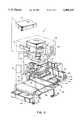
FIG. 2 illustrates another video strip reader in accordance with the present invention, generally designated by the reference numeral 11. Video reader 11 also includes avideo imager 12, an image handler 19, aprocessor 25 andstorage memory 27 that operate as the corresponding elements shown in FIG. 1, but the embodiment of FIG. 2 shows these elements as being together within ahousing 35 of the video test strip reader 11. Thehousing 35 prevents outside interference from adversely affecting test strip analysis. Theprocessor 25 can be a DSP (digital signal processor) on a dedicated board along withstorage memory 27. The image handler 19 can be a separate frame grabber board or a custom frame-grabber on the same or a different dedicated board. As stated above, the image handier 19 is described as including asignal converter 21. Thesignal converter 21 can be a conventional video analog to digital converter. Alternatively, theprocessor 25, the image handler 19 and thestorage memory 27 can take the form of hard-wired circuitry. As in FIG. 1, FIG. 2 shows anillumination source 13 shining on theviewing field 14 with atest strip 16. Theprocessor 25 is also shown as being coupled to a secondary storage, adisplay 31, aprinter 33, and akey pad 39.
In FIG. 2, the video strip reader 11 uses atransport mechanism 36 to transport thetest strip 16 from a loading area 38 into theviewing field 14 and into awaste receptacle 40. Although the loading area 38 is not shown as being in theviewing field 14 in FIG. 2, placement of the loading area 38 can be alternatively positioned within theviewing field 14. If the loading area 38 is in theviewing field 14, the test strip reader 11 can detect the placement of atest strip 16 onto theviewing field 14 by utilizing theprocessor 25 to analyze a current pixel array representing an image of theviewing field 14. Upon detecting the placement of atest strip 16 on theviewing field 14, theprocessor 25, which includes a known timing mechanism (not shown), keeps track of an elapsed time from the placement of thecorresponding test strip 16 on theviewing field 14. The timing mechanism of theprocessor 25 can include a system clock running at a known frequency. In the embodiment where theprocessor 25 detects the placement of thetest strip 16 on the loading area in theviewing field 14, theprocessor 25 is coupled to and signals thetransport mechanism 36 to transport thetest strip 16. Additionally, theprocessor 25 can control the movement of thetransport mechanism 36 according to the status of thevarious test strips 16 on theviewing field 14. For example, if all thetest strips 16 are finished, theprocessor 25 can signal thetransport mechanism 36 to transport thetest strips 16 to thewaste receptacle 40.
If the loading area 38 is not within theviewing field 14 as in FIG. 2, then aloading sensor 42 detects the placement of thetest strip 16 on the loading area 38 and signals theprocessor 25 that the operator has placed anew test strip 16 in the loading area 38. In this case, theloading area sensor 42 couples to theprocessor 25 by acontrol line 43. Upon receiving the loading area sensor signal from theloading area sensor 42, theprocessor 25 uses the timing mechanism to keep track of an elapsed time from the placement of thecorresponding test strip 16 on the loading area 38 as described above. Theloading area sensor 42 can include an optical interrupter utilizing a modulatedLED 44 and asynchronous photodetector 46. When atest strip 16 is placed on the loading area 38, a beam from theLED 44 is broken, and thephotodetector 46 detecting the corresponding signal change, triggers the loading area sensor signal from theloading area sensor 42 to theprocessor 25. Other apparatus or methods of detecting test strip placement are possible, such as motion detection by reflection of infrared light or ultrasonic pulses or detection of capacitance changes. In the embodiment of FIG. 2, this same loading area sensor signal also triggers thetransport mechanism 36 to move thetest strip 16 in theviewing field 14 either directly through a control line coupling theloading area sensor 42 to thetransport mechanism 36 or indirectly through a control line coupling theprocessor 25 to thetransport mechanism 36.
Thetransport mechanism 36 includes amotor control circuitry 49 that controls the operation of amotor 50. Themotor control circuitry 49 is coupled to themotor 50 and can vary widely in form depending on the embodiment. Themotor control circuitry 49 can be coupled directly to theloading area sensor 42, theprocessor 25 or both depending on the embodiment. If an embodiment utilizesprocessor 25 to determine the placement of atest strip 16 on the loading area and not a loading sensor, then themotor control circuitry 49 couples to theprocessor 25 through a control line. But if theloading area sensor 42 detects new strip placement as in FIG. 2, themotor control circuitry 49 can couple to theloading area sensor 42 through acontrol line 45 in order to receive loading area sensor signals. Themotor control circuitry 49 can alternatively couple to theprocessor 25 through acontrol line 47 to receive motor control signals from theprocessor 25 after theprocessor 25 receives a loading area sensor signal. FIG. 2 shows both theprocessor 25 and theloading sensor 42 coupled to themotor control circuitry 25, so both can signal themotor control circuitry 49.
In FIG. 2, thetransport mechanism 36 further includes themotor 50, astrip conveyor 48, amovement assembly 53, such as aconventional Geneva assembly 53, and ablotter arm 51. Themotor 50 provides the power to mechanically operate thetransport mechanism 36. Themotor 50 is mechanically linked to theGeneva assembly 53. TheGeneva assembly 53 is mechanically linked in a timed relation to thestrip conveyor 48 and theblotter arm 51 to coordinate the movement of both thestrip conveyor 48 and theblotter arm 51 according to the characteristics of theGeneva assembly 53. The coordinated movement of thestrip conveyor 48 and theblotter arm 51 efficiently indexes thetest strips 16 onto thestrip conveyor 48 as described below.
FIG. 2 shows theblotter arm 51 on the loading area 38. Whenever atest strip 16 is placed onto the loading area 38, themotor control circuitry 49 receives a signal from either theprocessor 25 or theloading area sensor 42. Themotor control circuitry 49 activatesmotor 50 causing theblotter arm 51 to move thetest strip 16 onto thestrip conveyer 48. Thetest strip 16 does not move on thestrip conveyor 48 until another test strip is placed in the loading area 38. At that time, theblotter arm 51 moves the next test strip onto thestrip conveyor 48 whileconveyor 48 moves the test strip 16 a fixed distance. Eachtest strip 16 in theviewing field 14 will move the same fixed distance with each subsequent index of another test strip. This calibrated and intermittent movement permits the proper indexing of test strips and is accomplished with theGeneva assembly 53. Consequently, thetransport mechanism 36 indexesmultiple test strips 16 in theviewing field 14 and, thereby, maximizes the number oftest strips 16 in theviewing field 14 and improves the efficiency of the video strip reader 11.
FIG. 3 shows animage 52 of theviewing field 14. Theimage 52 is composed of a two-dimensional array of pixels representing theviewing field 14. The upper left hand comer of theimage 52 represents the origin of this two-dimensional array with coordinates (0,0) in pixels. The x-axis pixel coordinates increase by moving horizontally from left to right across theimage 52 along a horizontal line of pixels, and the y-axis pixel coordinates increase vertically from top to bottom along a vertical column of pixels. Each pixel contains color information broken down into red, green or blue (RGB). Theprocessor 25 analyzes theimage 52 to determine the location and orientation of thetest strip 16 and itstest pads 28. When the elapsed time for thetest strip 16 exceeds an incubation time for atest pad 28 on thattest strip 16, theprocessor 25 measures the reflectance for that portion of the two dimensional pixel array orimage 52 representing that test area ortest pad 28. This step is repeated for multiple read times. Theprocessor 25 then calculates the concentration of the constituents of interest in the specimen or other test results.
Because of its video imaging capabilities, the present invention can utilizemarkings 54 incorporated on eachtest strip 16 to distinguish between individual test strips and different types of test strips. By utilizing a patient or sample ID on eachtest strip 16, the present invention can evaluate the alphanumeric or bar code information and report the results for each specimen or patient, reducing the possibility of human recording error. In addition, the ability to distinguish between different types of test strips enhances the flexibility of the present invention because the present invention can alter its analysis or timing to accommodate for the different type oftest strip 16.
The video strip reader of the present invention can also utilize acolor standard 56 contained in the viewing field to ensure that the present invention accurately analyzes the test strips. FIG. 3 illustrates acolor standard 56 on theimage 52 in the form of a color strip. By having acolor standard 56 on the viewing field, an absolute reflectance standard is always present for theprocessor 25 when analyzing theimage 52. The color standard 56 permits continuous correction for illumination changes. Alternatively, thecolor standard 56 can be located on the test strip itself.
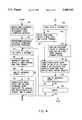
FIG. 4 is a flow chart diagram of the overall operation of the embodiment illustrated in FIG. 1. Initially,step 100 calibrates the reflectance for thevideo strip reader 10. Theprocessor 24 builds RGB reflectance reference matrices or calibration matrices for theviewing field 14 by reading the red, green and blue reflectance values for theviewing field 14. Step 102 calculates a background threshold for reflectance from the blue reflectance reference matrix. Theprocessor 24 rejects any reflectance values below the background threshold as noise, but reflectance values above the background threshold can represent the presence of atest strip 16 on theviewing field 14. Step 104 sets a loop in whichprocessor 24 cycles through steps 106-128 about every two seconds when unfinished test strips are present on theviewing field 14. Step 106 creates raw reflectance matrices for the red, green and blue colors (RGB) of theimage 52 by grabbing theRGB image 52 three times and averaging the raw pixel signals to complete the raw RGB reflectance matrices. Step 108 determines whether there are unfinished test strips on theviewing field 14. If not, theprocessor 24 proceeds to step 122 to detect any new test strips and classify any new test strips as "pending."
If unfinished test strips exist, theprocessor 24 performsstep 110 by checking everytest pad 28 on each unfinished test strip. Step 110 calculates the RGB reflectance values for each test pad with a current read time. Next, step 120 checks if a new test strip is "pending." If no new test strip is "pending," the processor proceeds to step 122 to detect any new test strips and classify any new strips as "pending." If a "pending" new test strip exists,step 124 finds the location for eachtest pad 28 by locating the four comers of eachtest pad 28 of a "pending" new test strip and releases the "pending" status of the new test strip.
After labeling any new test strips as "pending" or locating thetest pads 28 for a previously "pending" test strip, the present invention checks all test strips to determine whether a test strip is finished. Atest strip 16 is finished when the read time or times for everytest pad 28 on thetest strip 16 has expired and the RGB reflectance values for everytest pad 28 on the finished test strip was determined atstep 110. If atest strip 16 is finished, step 126 reports the test results derived from the timed RGB reflectance values for thattest strip 16. Finally,step 128 determines whether any unfinished strips remain. If so, theprocessor 24 cycles back to step 104, grabs a new set of RGB images, averages the raw pixel signals to construct another set of raw RGB reflectance matrices, and proceeds through the steps 106-128.
Theprocessor 24 performs an operation cycle every two seconds atstep 104. If all strips are finished,step 130 determines whether a predetermined amount of time has passed since a new test strip has been placed onto theviewing field 14. If the time limit has expired, the illustrative system stops, but if the time limit is not exceeded, theprocessor 24 continues cycling through steps 106-130 every two seconds.
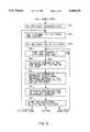
FIG. 5 details howstep 102 of FIG. 4 calculates the background threshold level for a background image in order to accomplish strip-edge detection ofsteps step 100 of FIG. 4. Step 202 calculates the average blue reflectance value for the background image using the blue reflectance reference matrix as well as the standard deviation. Step 204 determines the background threshold level with the equation:
THRESHOLD=AVERAGE+C * STANDARD DEVIATION,
where C is a factor from 3 to 8.
After the present invention determines that unfinished test strips exist atstep 108 of FIG. 4, step 110 of FIG. 4 checks every test pad on each unfinished test strip and calculates its RGB reflectance if the read time for the test pad has expired. FIG. 6 details the operation ofstep 110 of FIG. 4. Step 300 establishes an unfinished test strip loop based on the number of unfinished test strips. Step 302 adds two seconds to the time counter for an I-th unfinished test strip within the unfinished test strip loop ofstep 300. Step 304 establishes a test pad loop within the unfinished test strip loop based on the number of test pads for the I-th unfinished test strip. For a J-th test pad on the I-th unfinished test strip,step 306 determines whether the time counter or current time for the I-th unfinished test strip equals or exceeds the read time for the J-th test pad. If not, theprocessor 24 advances the test pad loop to the next test pad on the I-th unfinished test strip and proceeds back tostep 306.
Ifstep 306 determines that the read time of the J-th test pad on the I-th test strip has expired, theprocessor 24 must calculate the RGB reflectance values for the J-th pad. First,step 308 calculates an average raw RGB reflectance for the J-th test pad on the I-th test strip. Next, for the area corresponding to the J-th test pad on the I-th test strip,step 310 derives the average reflectance reference levels from the RGB reflectance reference matrices or calibration matrices ofstep 100. With the average reflectance reference levels and the average raw RGB reflectance corresponding to the J-th pad on the I-th strip,step 312 derives the RGB reflectance values for the J-th pad on the I-th strip. Step 314 stores the RGB reflectance values for the J-th pad on the I-th strip. If more test pads exist on the I-th test strip,processor 24 advances to the next test strip and proceeds to step 306. But if the test pad loop finishes, theprocessor 24 advances to the next test strip and proceeds to step 302. When the unfinished test strip loop finishes, the processor returns to step 120 of FIG. 4.
FIG. 7 details step 122 of FIG. 4 for detecting the presence of a new test strip on the viewing field. Step 400 begins by reading a predetermined low row from the raw blue reflectance matrix of the raw RGB reflectance matrices ofstep 106. Step 402 establishes an existing test strip loop. For each existing I-th test strip within the existing test strip loop,step 404 determines whether three consecutive pixels of the existing I-th test strip are below the background threshold level calculated in FIG. 5. If the three consecutive pixels of the existing I-th strip are below the background threshold level, then step 406 recognizes that the existing I-th test strip has been removed from theviewing field 14. But if the three consecutive pixels of the existing I-th test strip remain above the background threshold level,step 408 recognizes that the existing I-th test strip remains on theviewing field 14, and step 408 masks the pixels of the existing I-th test strip with the background threshold level.
After theprocessor 24 determines the status of all existing test strips and masks those pixels on the low row corresponding to existing test strips,processor 24 proceeds fromstep 410 to step 412. Step 412 detects the presence of new test strips by checking from left to right on the low row for three consecutive pixels above the background threshold value (three consecutive pixels were chosen only to provide good "noise" immunity), signalling the edge of a new test strip on theviewing field 14. Step 412 sets the status of any new test strip as "pending" and returns theprocessor 24 to step 126 of FIG. 1.
If, atstep 120, theprocessor 24 determines that a new strip is "pending" from the previous cycle through the new strip detection mechanism of FIG. 7,step 124 locates the four comers of each pad of a new strip and releases the "pending" status for a new test strip.
FIG. 8 details an initial portion ofstep 124 in whichprocessor 24 finds four boundary points for a "pending" new test strip. Step 500 reads a high row (Yh) and a low row (Yl) from the raw blue reflectance matrix ofstep 106. On those high and low rows selected bystep 500, step 502 masks pixels of existing test strips with the background level. Step 504 finds the left upper edge boundary point, X1h, of the "pending" new test strip by checking the high row from left to right to find the X1h that marks the boundary point between the background of theviewing field 14 and the "pending" new strip. Step 504 determines X1h by finding the point along tile high row, Yh, where the pixel values at X1h-2 and X1h-1 are less than the background threshold level and the pixel values at X1h+1 and X1h+2 are greater than the background threshold level.
After finding the left upper edge point, X1h, of the "pending" new strip atstep 504, theprocessor 24 locates the right upper edge boundary point, X2h, for the "pending" new test strip atstep 508. Step 508 finds X2h by checking the high row Yh to the right of X1h+3 and finding the point where the pixel values at X2h-2 and X2h-1 are greater than the background threshold level and the pixel values at X2h+1 and X2h+2 are less than the background threshold level. If either X1h or X2h is not found,processor 24 proceeds to step 530 to determine where the error occurred because any "pending" new strip must have these upper boundary points.
Similarly,processor 24 then locates the lower edge boundary points for a "pending" new test strip. Step 522 finds the left lower edge boundary point, X11, along the low row, Y1, ofstep 500. Step 522 searches for X11 along the low row such that the pixel values at X11-2 and X11-1 are less than the background threshold level and the pixel values at X11+1 and X11+2 are greater than the background threshold value. Finally,step 526 locates the right lower edge boundary point, X21, along Y1 for the "pending" new test strip. Step 526 finds X21 as the point along Y1 where the pixel values at X21-2 and X21-1 are greater than the background threshold level and the pixel values at X21+1 and X21+2 are less than the background threshold level. Step 524 or step 528 directsprocessor 24 to aerror handing step 530 ifprocessor 24 fails to find either lower edge boundary points, X11 or X21.
Upon reachingconnector 535,processor 24 has located the two upper edge boundary points along high row, Yh, and the two lower edge boundary points along low row, Y1. FIG. 9 shows howprocessor 24 takes the four edge boundary points and determines the test pad locations for a "pending" new test strip from these four edge boundary points. Step 540 ensures that the four edge boundary points are reasonable by checking the consistency of the four edge boundary points against values representing the minimum test strip width (MIN-- STRIP-- WIDTH), the maximum test strip width (MAX-- STRIP-- WIDTH) and the maximum angle offset (MAX-- ANGLE-- OFFSET). Step 540 checks if:
1) MIN-- STRIP-- WIDTH<X2h-X1h<MAX-- STRIP-- WIDTH;
2) MIN-- STRIP-- WIDTH<X21-X11<MAX-- STRIP-- WIDTH; and
3) X1h-X11<MAX-- ANGLE-- OFFSET. If the four edge boundary points are not consistent with atest strip 16,step 542 directs theprocessor 24 to anerror handing step 560. But if the four edge boundary points are consistent with atest strip 16,step 544 finds a middle line for the "pending" new strip. Step 544 derives the middle line equation for the new test strip with the following proportion: ##EQU1##
Step 546 finds the top edge of the top test pad on the test strip. Step 546 checks along the middle line from the top and searches for a Y1 where the pixel values at Y1, Y1+1 and Y1+2 are greater than the background threshold value. According to the MULTISTIX® reagent test strips currently used, the top edge of the top test pad forms the top edge of the test strip itself as shown in FIG. 3. If a top edge is not found,step 548 directsprocessor 24 to theerror handling step 560. Ifstep 546 finds a top edge for the top test pad,step 550 finds the bottom edge of the bottom test pad. Step 550 searches along the middle line from the bottom for a Y2 such that the pixel values at Y2-2, Y2-1 and Y2 are greater than the background threshold level and the pixel values at Y2+1 and Y2+2 are greater than a white background threshold level. If a bottom edge is not found,step 552 directs theprocessor 24 to theerror handling step 560. Otherwise,step 554 calculates the four corners for each test pad using Y1, Y2, the middle line for the test strip and the known test pad characteristics for thetest strip 16. Finally, step 554 releases the "pending" status for thetest strip 16.
After completing either step 122 or step 124 of FIG. 4,processor 24 proceeds to step 126 in order to finish unfinished test strips. FIG. 10 details step 126 of FIG. 4. Step 600 establishes a loop based on the number of unfinished test strips. For each I-th unfinished test strip within the unfinished test strip loop,step 602 determines whether theprocessor 24 has sampled final timed RGB reflectance values of the last pad on the I-th unfinished test strip. If not, the test pad remains unfinished, and theprocessor 24 moves to the next unfinished test strip. If theprocessor 24 has sampled the last pad, then thetest strip 16 is finished, and step 604 calculates the readings for eachpad 28 of thetest strip 16 using the timed RGB reflectance values for thattest pad 28. After calculating the readings for the finished test pad, step 606 reports the test results for the finished test strip.
The present invention has been described as using a color CCD camera. The present invention, however, can employ a monochrome camera using color filters. Typically, the monochrome camera has a higher resolution than color cameras and the use of the monochrome camera arrangement can be advantageous. Also, the present invention is described as scanning the blue matrix of the raw RGB reflectance matrices to detect a new test strip and the RGB reflectance reference matrices to locate the pads on a "pending" new strip. The present invention, however, encompasses scanning any color matrix to perform these functions. Additionally, the present invention also encompasses constructing new RGB reflectance reference matrices or calibration matrices periodically in order to provide updated RGB reflectance reference matrices.
Thus, the video test strip reader and method of the present invention and many of its attendant advantages will be understood from the foregoing description and various modifications may be made in the form, construction and arrangement of the parts thereof without departing from the spirit and scope of the invention or sacrificing all of its material advantages, the form described above being merely a preferred embodiment thereof.
Claims (59)
1. A video test strip reader for reading reagent test strips, said test strips each having test pads, each of said test pads reacting with a sample when contacting said sample and changing color according to one or more read times for each of said test pads and an amount of a constituent or property in said sample, comprising:
a video imager adjacent to a viewing area for converting an image of said viewing area to an analog signal representing said image;
a signal converter responsive to said analog signal, said signal converter converting said analog signal into a digital signal representing said image;
an image handler responsive to said digital signal, said image handler storing said image represented by said digital signal; and
a processor coupled to said image handler for analyzing said image to determine a placement of a test strip at any location on said viewing area, said processor determining the location and orientation of a test strip on said viewing area and identifying a test pad for said test strip, said processor including a timing mechanism for tracking an elapsed time from said placement of each of said test strips, said processor analyzing a portion of said image representing an identified test pad of said test strip after said read times for said test pad, said processor calculating said amount of said constituent or property in said sample from said analysis of said portion of said image.
2. The video reader of claim 1 further comprising a transport mechanism with at least a portion of said transport mechanism being in said viewing field, said transport mechanism transporting said test strips across said viewing field.
3. The video test strip reader of claim 1 wherein said video imager is a color camera.
4. The video test strip reader of claim 1 wherein said video imager is a monochrome camera having a plurality of color filters.
5. The video test strip reader of claim 3 or 4 wherein said image handler is a frame-grabber board.
6. The video test strip reader of claim 5 wherein said processor includes a conventional personal computer, said frame-grabber board coupled to an I/O port of said personal computer.
7. The video test strip reader of claim 1 wherein said video imager includes said signal converter.
8. The video test strip reader of claim 1 wherein said image handler includes said signal converter.
9. The video test strip reader of claim 1 wherein said processor is a DSP processor on a dedicated board.
10. The video test strip reader of claim 1 further comprising an illumination source illuminating said viewing area.
11. The video test strip reader of claim 1 further comprising a storage memory coupled to said processor, said processor storing reference values in said storage memory, said processor using said reference values to calibrate said video test strip reader and compensate for any illumination variations on the viewing area.
12. The video test strip reader of claim 1 further comprising a displayer coupled to said processor.
13. A video test strip reader for reading reagent test strips, said test strips each having test pads, each of said test pads reacting with a sample when contacting said sample and changing color in proportion with one or more read times for each of said test pads and an amount of a constituent or property in said sample, comprising:
a video imager adjacent to a viewing area for converting an image of said viewing area to an analog signal representing said image;
a signal converter responsive to said analog signal, said signal converter converting said analog signal into a digital signal representing said image;
an image handler responsive to said digital signal, said image handler storing said image represented by said digital signal;
a transport mechanism with at least a portion of said transport mechanism being in said viewing area, said transport mechanism receiving said test strips and transporting said test strips across said viewing area; and
a processor coupled to said image handler for analyzing said image to determine a location and orientation for a test strip placed at any location on said viewing area, said processor identifying a test pad relative to said location and orientation for said test strip, said processor including a timing mechanism for tracking an elapsed time from the placement of said test strip, said processor analyzing a portion of said image representing a test pad of said test strip after said read time for said test pad, said processor calculating said amount of said constituent in said sample from said analysis of said portion of said image.
14. The video test strip reader of claim 13 wherein said transport mechanism has a loading end and a waste end, said viewing area is between said loading end and said waste end, said transport mechanism receives said test strips at said loading end, said transport mechanism transports said test strips across said viewing area for analysis and deposits said test strips in a waste receptacle at said waste end.
15. The video test strip reader of claim 14 further comprising a loading sensor at said loading end of said transport mechanism, said loading sensor signalling said processor that said transport mechanism has received said test strip, said processor triggering said timing mechanism for said test strip upon receiving said signal.
16. The video test strip reader of claim 15 wherein said loading sensor includes an optical interrupter utilizing a modulated light source and a synchronous photodetector such that said light source shines a light beam across said loading end of said transport mechanism directly at said photodetector, said light beam is broken upon said transport mechanism receiving said test strip, said loading sensor signals said processor upon receiving said test strip.
17. The video test strip reader of claim 13 wherein said video imager is a color camera.
18. The video test strip reader of claim 13 wherein said video imager is a monochrome camera having a plurality of color filters.
19. The video test strip reader of claim 17 or 18 wherein said image handler is a frame-grabber board.
20. The video test strip reader of claim 19 wherein said processor includes a conventional personal computer, said frame-grabber board is coupled to an I/O port of said personal computer.
21. The video test strip reader of claim 13 wherein said video imager includes said signal converter.
22. The video test strip reader of claim 13 wherein said image handler includes said signal converter.
23. The video test strip reader of claim 13 wherein said processor is a DSP processor on a dedicated board.
24. The video test strip reader of claim 13 further comprising an illumination source illuminating said viewing area.
25. The video test strip reader of claim 13 further comprising a storage memory coupled to said processor, said processor storing reference values in said storage memory, said processor using said reference values to calibrate said video test strip reader and compensate for any illumination variations on the viewing area.
26. The video test strip reader of claim 13 further comprising a displayer coupled to said processor.
27. A video test strip analyzer for analyzing an image represented by a digital signal, said image being of a viewing field with reagent test strips, said test strips each having test pads, each of said test pads reacting with a sample when contacting said sample and changing color according to one or more read times for each of said test pads and an amount of a constituent or property in said sample, comprising a processor analyzing said image to determine a location and orientation for a test strip placed at any location on said viewing area, said processor identifying a test pad for said test strip, said processor including a timing mechanism for tracking an elapsed time from said placement of said test strip, said processor analyzing a portion of said image representing a test pad of said test strip after said read times for said test pad, said processor calculating said amount of said constituent or property in said sample from said analysis of said portion of said image.
28. The video test strip analyzer of claim 27 wherein said processor includes a conventional personal computer.
29. The video test strip analyzer of claim 27 wherein said processor is a DSP processor on a dedicated board.
30. The video test strip analyzer of claim 27 further comprising a storage memory coupled to said processor, said processor storing reference values in said storage memory, said processor using said reference values to calibrate said video test strip reader and compensate for any illumination variations on the viewing area.
31. The video test strip analyzer of claim 27 further comprising a displayer coupled to said processor.
32. A method for reading reagent test strips each having test pads, each of said test pads reacting with a sample when contacting said sample and changing color in proportion to one or more read times for each of said test pads and an amount of a constituent or property in said sample, comprising the steps of:
converting an image of a viewing area into a digital signal representing said image;
storing said digital signal representing said image;
detecting a test strip placed at any location on said viewing area by analyzing said digital signal representing said image;
determining the location and orientation of said test strip on said image;
identifying portions of said image representing a test pad on said test strip;
timing said test strip starting at said detection of said test strip to obtain a current time for said test strip;
determining whether said read time for said test pad has expired by comparing said read time with the current time for said test strip;
analyzing said portion of said image representing said expired test pad to obtain a raw reflectance value for a portion of said image representing said expired test pad; and
calculating said mount of said constituent or property in said sample from said raw reflectance value for said portion of said image representing said expired test pad.
33. The method of claim 32 further comprising the initial steps of:
converting a reflectance reference image into a digital signal;
storing said digital signal in reflectance reference matrices; and
obtaining a threshold signal level from said reflectance reference matrices.
34. The method of claim 33 wherein said step of calculating further comprises compensating said raw reflectance value with said reflectance reference matrices to correct illumination variations on said viewing area and to obtain a reflectance value for said expired test pad.
35. The method of claim 32 further comprising the step of transporting said test strip across said viewing field.
36. The method of claim 32 further comprising the step of displaying results from said calculation.
37. The method of claim 32 wherein said steps following said step of converting further comprise employing a conventional personal computer.
38. The method of claim 32 wherein said steps following said step of converting further comprise employing a DSP processor on a dedicated board.
39. The method of claim 32 further comprising the step of illuminating said viewing area.
40. A method for reading reagent test strips each having test pads, each of said test pads reacting with a sample when contacting said sample and changing color according to one or more read times for each of said test pads and an amount of a constituent or property in said sample, comprising the steps of:
receiving a test strip;
transporting said test strip across a viewing area;
converting an image of said viewing area into a digital signal representing said image;
storing said digital signal representing said image;
determining a location and orientation for said test strip at any location on said viewing area by analyzing said image represented by said digital signal;
identifying portions of said image relative to said location and orientation representing a test pad on said test strip;
timing said test strip starting at said receiving of said test strip to obtain a current time for said test strip;
determining whether said read time for said test pads of said test strip has expired by comparing said read time with said current time for said test strip;
analyzing a portion of said image representing said expired test pad to obtain a raw reflectance value for said portion of said image representing said expired test pad: and
calculating said amount of said constituent or property in said sample from said raw reflectance value for said portion of said image representing said expired test pad.
41. The method of claim 40 further comprising the initial steps of:
converting a reflectance reference image into a digital signal;
storing said digital signal in reflectance reference matrices; and
obtaining a threshold signal level from said reflectance reference matrices.
42. The method of claim 41 wherein said step of calculating further comprises compensating said raw reflectance value with said reflectance reference matrices to correct illumination variations on said viewing area and to obtain a reflectance value for said expired test pad.
43. The method of claim 40 wherein said step of receiving further comprises receiving said test strip at a loading end of a transport mechanism.
44. The method of claim 40 further comprising the step of depositing said test strips in a waste receptacle at said waste end of said transport mechanism.
45. The method of claim 43 wherein said step of receiving further comprises the steps of:
employing a loading sensor at said loading end of said transport mechanism for detecting said receiving said test strip;
providing a signal that said transport mechanism has received said test strip; and
triggering a timing mechanism with said signal for said test strip.
46. The method of claim 45 further comprising the steps of:
employing an optical interrupter utilizing a modulated light source and a synchronous photodetector such that said light source shines a light beam across said loading end of said transport mechanism directly at said photodetector as said loading sensor: and
providing said signal upon said light beam being broken.
47. The method of claim 40 wherein said step of converting further comprises the step of employing a color camera.
48. The method of claim 40 wherein said step of converting further comprises the step of employing a monochrome camera having a plurality of color filters.
49. The method of claim 40 wherein said steps following said step of converting further comprise the step of employing a conventional personal computer.
50. The method of claim 40 further comprising the step of displaying results from said calculation.
51. The method of claim 40 wherein said steps following said step of converting further comprise employing a conventional personal computer.
52. The method of claim 40 wherein said steps following said step of converting further comprise employing a DSP processor on a dedicated board.
53. The method of claim 40 further comprising the step of illuminating said viewing area.
54. A method for analyzing an image represented by a digital signal, said image being of a viewing field with reagent test strips each having test pads, each of said test pads reacting with a sample when contacting said sample and changing color according to one or more read times for each of said test pads and an amount of a constituent or property in said sample, comprising the steps of:
determining a location and orientation of a test strip placed at any location on said viewing field;
identifying portions of said image representing a test pad on said test strip;
timing said test strip to obtain a current time for said test strip;
determining whether said read time for said test pad on said test strip has expired by comparing said read time with the current time for said test strip;
analyzing said portion of said image representing said expired test pad to obtain a raw reflectance value for a portion of said image representing said expired test pad; and
calculating said amount of said constituent or property in said sample from said raw reflectance value for said portion of said imaging representing said expired test pad.
55. The method of claim 54 further comprising the initial steps of:
constructing reflectance reference matrices from a digital signal representing a reflectance reference image; and
obtaining a threshold signal level from said reflectance reference matrices.
56. The method of claim 55 wherein said step of calculating further comprises compensating said raw reflectance value with said reflectance reference matrices to correct illumination variations on said viewing area and to obtain a reflectance value for said expired test pad.
57. The method of claim 54 further comprising the step of outputting said results from said calculation.
58. The method of claim 54 further comprising employing a conventional personal computer.
59. The method of claim 54 further comprising employing a DSP processor on a dedicated board.
Priority Applications (7)
| Application Number | Priority Date | Filing Date | Title |
|---|---|---|---|
| US08/117,782US5408535A (en) | 1993-09-07 | 1993-09-07 | Video test strip reader and method for evaluating test strips |
| AU70327/94AAU661945B2 (en) | 1993-09-07 | 1994-08-17 | Video test strip reader and method for evaluating test strips |
| AT94113313TATE254279T1 (en) | 1993-09-07 | 1994-08-25 | VIDEO TEST STRIP READER AND METHOD FOR ASSESSING TEST STRIPS |
| EP94113313AEP0646784B1 (en) | 1993-09-07 | 1994-08-25 | Video test strip reader and method for evaluating test strips |
| DE69433317TDE69433317T2 (en) | 1993-09-07 | 1994-08-25 | Video test strip reader and method for evaluating test strips |
| CA002130970ACA2130970A1 (en) | 1993-09-07 | 1994-08-26 | Video test strip reader and method for evaluating test strips |
| JP21280294AJP3628727B2 (en) | 1993-09-07 | 1994-09-06 | Video test strip reader and test strip evaluation method |
Applications Claiming Priority (1)
| Application Number | Priority Date | Filing Date | Title |
|---|---|---|---|
| US08/117,782US5408535A (en) | 1993-09-07 | 1993-09-07 | Video test strip reader and method for evaluating test strips |
Publications (1)
| Publication Number | Publication Date |
|---|---|
| US5408535Atrue US5408535A (en) | 1995-04-18 |
Family
ID=22374786
Family Applications (1)
| Application Number | Title | Priority Date | Filing Date |
|---|---|---|---|
| US08/117,782Expired - LifetimeUS5408535A (en) | 1993-09-07 | 1993-09-07 | Video test strip reader and method for evaluating test strips |
Country Status (7)
| Country | Link |
|---|---|
| US (1) | US5408535A (en) |
| EP (1) | EP0646784B1 (en) |
| JP (1) | JP3628727B2 (en) |
| AT (1) | ATE254279T1 (en) |
| AU (1) | AU661945B2 (en) |
| CA (1) | CA2130970A1 (en) |
| DE (1) | DE69433317T2 (en) |
Cited By (128)
| Publication number | Priority date | Publication date | Assignee | Title |
|---|---|---|---|---|
| US5905808A (en)* | 1997-03-13 | 1999-05-18 | Ortho Diagnostic Systems, Inc. | Method and apparatus for calibrating imaging systems for analyzing agglutination reactions |
| US6097831A (en)* | 1997-10-14 | 2000-08-01 | Chiron Corporation | Non-contract method for assay reagent volume dispense verification |
| USD432244S (en)* | 1998-04-20 | 2000-10-17 | Adeza Biomedical Corporation | Device for encasing an assay test strip |
| USD434153S (en)* | 1998-04-20 | 2000-11-21 | Adeza Biomedical Corporation | Point of care analyte detector system |
| US6261522B1 (en)* | 1998-10-13 | 2001-07-17 | Bayer Corporation | Spectrophotometric apparatus with reagent strip detection |
| US6267722B1 (en) | 1998-02-03 | 2001-07-31 | Adeza Biomedical Corporation | Point of care diagnostic systems |
| US20010034068A1 (en)* | 1998-07-14 | 2001-10-25 | Spivey Robin James | Screening device and methods of screening immunoassay tests and agglutination tests |
| US6394952B1 (en) | 1998-02-03 | 2002-05-28 | Adeza Biomedical Corporation | Point of care diagnostic systems |
| WO2002071044A1 (en)* | 2001-02-28 | 2002-09-12 | Home Diagnostics, Inc. | Distinguishing test types through spectral analysis |
| US20020136436A1 (en)* | 2001-02-23 | 2002-09-26 | Schrier Wayne H. | Devices and methods for reading and interpreting guaiac-based occult blood tests |
| US20030003436A1 (en)* | 2001-02-05 | 2003-01-02 | Willson C. Grant | Use of mesoscale self-assembly and recognition to effect delivery of sensing reagent for arrayed sensors |
| US6511814B1 (en) | 1999-03-26 | 2003-01-28 | Idexx Laboratories, Inc. | Method and device for detecting analytes in fluids |
| US6514461B1 (en)* | 1997-02-14 | 2003-02-04 | Escreen, Inc. | System for automatically testing a fluid specimen |
| US6551842B1 (en) | 1999-03-26 | 2003-04-22 | Idexx Laboratories, Inc. | Method and device for detecting analytes in fluids |
| US6567170B2 (en)* | 2001-06-25 | 2003-05-20 | Xerox Corporation | Simultaneous plural colors analysis spectrophotometer |
| US6602719B1 (en) | 1999-03-26 | 2003-08-05 | Idexx Laboratories, Inc. | Method and device for detecting analytes in fluids |
| US20030179445A1 (en)* | 1999-10-29 | 2003-09-25 | Garrick Maenle | Cytological imaging systems and methods |
| US20030187590A1 (en)* | 2002-03-28 | 2003-10-02 | Yoshihide Iwaki | Humoral testing unit |
| US20030185711A1 (en)* | 2002-03-28 | 2003-10-02 | Yoshihide Iwaki | Humoral testing apparatus |
| US20030186457A1 (en)* | 2002-03-28 | 2003-10-02 | Yoshihide Iwaki | Blood testing unit and blood testing method and apparatus |
| US20030207441A1 (en)* | 2002-05-01 | 2003-11-06 | Eyster Curt R. | Devices and methods for analyte concentration determination |
| US20030206302A1 (en)* | 2002-05-01 | 2003-11-06 | Pugh Jerry T. | Apparatuses and methods for analyte concentration determination |
| RU2217755C2 (en)* | 2001-05-23 | 2003-11-27 | Научно-исследовательский институт морфологии человека РАМН | Method for giving quantitative estimation of immunochromatographic analysis results |
| RU2217756C2 (en)* | 2001-05-23 | 2003-11-27 | Научно-исследовательский институт морфологии человека РАМН | Method for giving quantitative estimation of immunoenzyme analysis results |
| US6661501B1 (en) | 1999-10-29 | 2003-12-09 | Cytyc Corporation | Cytological stain composition including verification characteristic |
| US6665060B1 (en) | 1999-10-29 | 2003-12-16 | Cytyc Corporation | Cytological imaging system and method |
| US20040131238A1 (en)* | 2003-01-02 | 2004-07-08 | Veutron Corporation | Method for detecting a response of each probe zone on a test strip |
| US20040162690A1 (en)* | 2002-11-19 | 2004-08-19 | Lee Jin Po | Method and system for analyzing test devices |
| US20050003522A1 (en)* | 2003-05-19 | 2005-01-06 | Lattec I/S | Apparatus for analysing fluid taken from a body |
| US20050019796A1 (en)* | 2003-05-16 | 2005-01-27 | Meiring Jason E. | Image and part recognition technology |
| US20050064452A1 (en)* | 2003-04-25 | 2005-03-24 | Schmid Matthew J. | System and method for the detection of analytes |
| US20050095697A1 (en)* | 2003-11-04 | 2005-05-05 | Bachur Nicholas R.Jr. | Apparatus and method for using optical mouse engine to determine speed, direction, position of scanned device and to obtain quantitative or qualitative data from same |
| US20050160092A1 (en)* | 2004-01-16 | 2005-07-21 | Xerox Corporation | Reference database and method for determining spectra using measurements from an LED color sensor, and method of generating a reference database |
| US20050163661A1 (en)* | 2001-11-20 | 2005-07-28 | Ziegler Walter M. | Test strip analysis apparatus |
| US20050168747A1 (en)* | 2004-01-29 | 2005-08-04 | Fox Shaw G. | Information-encoded tests and method |
| WO2005088519A1 (en)* | 2004-03-05 | 2005-09-22 | Bayer Healthcare Llc | Hadheld optical diagnostic device having image system array |
| US20050237531A1 (en)* | 2004-03-05 | 2005-10-27 | Roman Juan F | Miniature optical readhead for optical diagnostic device |
| US20060018792A1 (en)* | 2004-07-20 | 2006-01-26 | Stock Nicholas T | Read-head for optical diagnostic device |
| US7006674B1 (en) | 1999-10-29 | 2006-02-28 | Cytyc Corporation | Apparatus and methods for verifying the location of areas of interest within a sample in an imaging system |
| US20060094127A1 (en)* | 2003-05-22 | 2006-05-04 | Wen-Chao Tseng | Method of automatically detecting a test result of a probe zone of a test strip |
| US20060104499A1 (en)* | 1999-10-29 | 2006-05-18 | Cytyc Corporation | Apparatus and methods for verifying the location of areas of interest within a sample in an imaging system |
| US20060152718A1 (en)* | 2005-01-13 | 2006-07-13 | Xerox Corporation | Systems and methods for selecting a reference database for determining a spectrum of an object based on fluorescence of the object |
| US20060222567A1 (en)* | 2005-04-01 | 2006-10-05 | Hafellner | Body fluid testing component for simultaneous analyte detection |
| US20060263902A1 (en)* | 2005-05-23 | 2006-11-23 | Bayer Healthcare Llc | Dispensing of a diagnostic liquid onto a diagnostic reagent |
| US20070123782A1 (en)* | 2005-11-30 | 2007-05-31 | Jackson Connolly | On-site healthcare diagnostic device |
| US7267799B1 (en)* | 2002-08-14 | 2007-09-11 | Detekt Biomedical, L.L.C. | Universal optical imaging and processing system |
| US20070223781A1 (en)* | 2002-12-27 | 2007-09-27 | Kuo-Jeng Wang | Method for determining a response of each probe zone on a test strip |
| US20070253867A1 (en)* | 2006-04-26 | 2007-11-01 | Kaiwood Technology Co., Ltd. | Cylindrical reagent chip analyzer |
| US20080023647A1 (en)* | 2006-01-31 | 2008-01-31 | Patel Gordhanbhai N | General purpose, high accuracy dosimeter reader |
| US20080186499A1 (en)* | 2005-05-18 | 2008-08-07 | Siemens Medical Solutions Diagnostics | Verification Apparatus and Methods For Optical Inpection Machine |
| US20080219499A1 (en)* | 2007-03-10 | 2008-09-11 | Walter Jay Gregory | Method for reading test strips |
| US20080254544A1 (en)* | 2007-04-12 | 2008-10-16 | Modzelewski Brent E | Error detection and rejection for a diagnostic testing system |
| WO2008130643A1 (en)* | 2007-04-18 | 2008-10-30 | Iris International, Inc. | Chemistry strip reader and method |
| US20080267445A1 (en)* | 2007-04-18 | 2008-10-30 | Dale Capewell | Chemistry strip reader and method |
| US20090116015A1 (en)* | 2006-04-08 | 2009-05-07 | Roche Diagnostics Operations, Inc. | Analysis of Optical Data with the Aid of Histograms |
| US20090128816A1 (en)* | 2007-11-20 | 2009-05-21 | Siemens Medical Solutions Diagnostics | Miniature Optical Readhead and Colorimeter for Analysis Media |
| WO2009063185A1 (en)* | 2007-11-14 | 2009-05-22 | Surescreen Diagnostics Limited | Test results reading method and apparatus |
| US20090154776A1 (en)* | 2007-12-12 | 2009-06-18 | Jadak, Llc | Optical Imaging Clinical Sampler |
| US20090304247A1 (en)* | 2006-12-20 | 2009-12-10 | Wolfgang Petrich | Measurement system with optical referencing |
| US20090316140A1 (en)* | 2001-01-17 | 2009-12-24 | Siemens Healthcare Diagnostics Inc. | Method and apparatus for using infrared readings to detect misidentification of a diagnostic test strip in a reflectance spectrometer |
| US20100045789A1 (en)* | 2008-08-22 | 2010-02-25 | Fleming James E | Apparatus, method and article to perform assays using assay strips |
| US20100239137A1 (en)* | 2007-10-09 | 2010-09-23 | Siemens Healthcare Diagnostics Inc. | Two Dimensional Imaging of Reacted Areas On a Reagent |
| US20100284583A1 (en)* | 2007-08-22 | 2010-11-11 | Phadia Ab | Read-out method and apparatus |
| US20100315644A1 (en)* | 2009-04-07 | 2010-12-16 | Nexus Dx, Inc. | Hand-held scanner systems and methods for reading point of care test results |
| US20110111522A1 (en)* | 2007-08-30 | 2011-05-12 | Siemens Healthcare Diagnostics Inc. | Non-visible detectable marking for medical diagnostics |
| US20110198487A1 (en)* | 2008-10-21 | 2011-08-18 | Bayer Healthcare Llc | Optical readhead and method of using the same |
| US20110223673A1 (en)* | 2008-11-19 | 2011-09-15 | Siemens Healthcare Diagnostics Inc. | Polarized Optics for Optical Diagnostic Device |
| US20110244590A1 (en)* | 2010-03-31 | 2011-10-06 | Fujifilm Corporation | Analysis apparatus and method |
| CN102244789A (en)* | 2010-05-12 | 2011-11-16 | 索尼公司 | Imaging apparatus |
| US20110293153A1 (en)* | 2008-11-14 | 2011-12-01 | Optricon Gmbh | Appliance and method for evaluation and assessment of a test strip |
| US20120063652A1 (en)* | 2010-09-15 | 2012-03-15 | Teco Diagnostics | Method and apparatus for performing color-based reaction testing of biological materials |
| US20120178101A1 (en)* | 2009-09-03 | 2012-07-12 | Infopia Co., Ltd. | Device, method, and system for quantitatively measuring a specimen using a camera |
| CN102608107A (en)* | 2011-01-20 | 2012-07-25 | 中研应用感测科技股份有限公司 | Automatic test piece interpretation method and system |
| US20120188378A1 (en)* | 2011-01-20 | 2012-07-26 | Middleland Sensing Technology Inc. | Automatic analyzing method and system for test strips |
| US20120329170A1 (en)* | 2011-06-23 | 2012-12-27 | Ushio Inc. | Analyzing apparatus and analyzing method |
| WO2013096804A2 (en) | 2011-12-23 | 2013-06-27 | Abbott Point Of Care Inc | Optical assay device with pneumatic sample actuation |
| WO2013096817A2 (en) | 2011-12-23 | 2013-06-27 | Abbott Point Of Care Inc | Integrated test device for optical detection of microarrays |
| US8506901B2 (en) | 2010-11-03 | 2013-08-13 | Teco Diagnostics | All-in-one specimen cup with optically readable results |
| WO2013173674A1 (en) | 2012-05-18 | 2013-11-21 | Siemens Healthcare Diagnostics Inc. | Fish eye lens analyzer |
| WO2014015420A1 (en)* | 2012-07-24 | 2014-01-30 | Fio Corporation | Immunoassay rapid diagnostic test universal analysis device, system, method and computer readable medium |
| EP2733217A1 (en) | 2009-01-26 | 2014-05-21 | Siemens Healthcare Diagnostics Inc. | Device and method for detection of humidity-compromised urine test strips |
| CN103988065A (en)* | 2011-12-16 | 2014-08-13 | 西门子医疗保健诊断公司 | Reagent Card Alignment Systems and Methods |
| CN104040321A (en)* | 2011-11-23 | 2014-09-10 | 卡尔马克瑞典股份公司 | Testing system arrangement and method for testing |
| US20140286550A1 (en)* | 2013-03-21 | 2014-09-25 | Microdiscovery Gmbh | Portable reader module, portable reader, and method for quantitative analysis of an assay |
| WO2015038717A1 (en)* | 2013-09-11 | 2015-03-19 | Wellumina Health, Inc. | System for diagnostic testing of liquid samples |
| US9113235B2 (en) | 2012-11-14 | 2015-08-18 | Symbol Technologies, Llc | Device and method for functionality sequencing |
| US9188510B2 (en)* | 2009-02-26 | 2015-11-17 | Chemspectra, Inc. | Test swipe for portable explosive or drug detection system |
| US9194859B2 (en) | 2011-12-23 | 2015-11-24 | Abbott Point Of Care Inc. | Reader devices for optical and electrochemical test devices |
| US9228953B2 (en) | 2011-11-23 | 2016-01-05 | Calmark Sweden Ab | Testing system and method for testing |
| CN105223194A (en)* | 2015-09-29 | 2016-01-06 | 上海新窝信息科技有限公司 | A kind of integrated urine examination method and system |
| CN105241875A (en)* | 2015-09-29 | 2016-01-13 | 上海新窝信息科技有限公司 | Urinalysis method and system |
| US9285323B2 (en) | 2012-08-08 | 2016-03-15 | Scanadu Incorporated | Quantifying color changes of chemical test pads induced concentrations of biological analytes under different lighting conditions |
| US9311520B2 (en) | 2012-08-08 | 2016-04-12 | Scanadu Incorporated | Method and apparatus for performing and quantifying color changes induced by specific concentrations of biological analytes in an automatically calibrated environment |
| US9317922B2 (en) | 2003-05-16 | 2016-04-19 | Board Of Regents The University Of Texas System | Image and part recognition technology |
| JP2016061747A (en)* | 2014-09-20 | 2016-04-25 | テラメックス株式会社 | Test unit and sample analyzer |
| US9335290B2 (en) | 2011-12-23 | 2016-05-10 | Abbott Point Of Care, Inc. | Integrated test device for optical and electrochemical assays |
| EP2941630A4 (en)* | 2013-01-07 | 2016-08-24 | Ixensor Inc | REACTIVE STRIPS AND METHOD FOR REACTIVE STRIP READING |
| US9466104B2 (en) | 2012-04-06 | 2016-10-11 | Ixensor Inc. | Reading test strip with multiple reaction areas under different exposures or light intensities |
| US9465023B2 (en) | 2013-08-05 | 2016-10-11 | Siemens Healthcare Diagnostis Inc. | Device and method for unit use sensor testing |
| US9528941B2 (en) | 2012-08-08 | 2016-12-27 | Scanadu Incorporated | Method and apparatus for determining analyte concentration by quantifying and interpreting color information captured in a continuous or periodic manner |
| US9569858B2 (en) | 2014-02-13 | 2017-02-14 | James Bennett Babcock | Cloud-based system for water analysis |
| US9679180B2 (en) | 2014-12-23 | 2017-06-13 | Symbol Technologies, Llc | Portable data capture device |
| US9778200B2 (en) | 2012-12-18 | 2017-10-03 | Ixensor Co., Ltd. | Method and apparatus for analyte measurement |
| US20170299502A1 (en)* | 2016-04-19 | 2017-10-19 | Ariana Schanzer | Contaminant monitor system and method |
| CN107561255A (en)* | 2017-10-19 | 2018-01-09 | 杨勇 | The apparatus and method for detecting drugs content in urine |
| US9863811B2 (en) | 2014-08-15 | 2018-01-09 | Scanadu Incorporated | Precision luxmeter methods for digital cameras to quantify colors in uncontrolled lighting environments |
| US9973671B2 (en) | 2014-08-27 | 2018-05-15 | Symbol Technologies, Llc | Method and apparatus for directing data capture devices in a mobile unit with a single operation |
| CN108226546A (en)* | 2017-12-21 | 2018-06-29 | 新绎健康科技有限公司 | A kind of localization method of test paper color lump |
| WO2018194525A1 (en) | 2017-04-18 | 2018-10-25 | Yeditepe Universitesi | Biochemical analyser based on a machine learning algorithm using test strips and a smartdevice |
| TWI672491B (en)* | 2017-03-13 | 2019-09-21 | 美商碩騰服務有限責任公司 | A lateral flow test system |
| CN110431401A (en)* | 2016-12-15 | 2019-11-08 | 拜克门寇尔特公司 | Shear pad detection system and method |
| WO2019222081A1 (en)* | 2018-05-14 | 2019-11-21 | Reliant Immune Diagnostics, Inc. | System and method for image processing of medical test results using generalized curve field transform |
| US10576475B2 (en) | 2016-09-15 | 2020-03-03 | Genprime, Inc. | Diagnostic assay strip cassette |
| US10690597B2 (en) | 2009-01-26 | 2020-06-23 | Siemens Healthcare Diagnostics Inc. | Device and method for detection of humidity-compromised urine test strips |
| US10983065B2 (en) | 2012-08-08 | 2021-04-20 | Healthy.Io Ltd. | Method, apparatus and system for detecting and determining compromised reagent pads by quantifying color changes induced by exposure to a hostile environment |
| US10991096B2 (en) | 2014-05-12 | 2021-04-27 | Healthy.Io Ltd. | Utilizing personal communications devices for medical testing |
| US11030778B2 (en) | 2014-03-31 | 2021-06-08 | Healthy.Io Ltd. | Methods and apparatus for enhancing color vision and quantifying color interpretation |
| US11087467B2 (en) | 2014-05-12 | 2021-08-10 | Healthy.Io Ltd. | Systems and methods for urinalysis using a personal communications device |
| US11158420B2 (en) | 2019-01-02 | 2021-10-26 | Healthy.Io Ltd. | Tracking wound healing progress using remote image analysis |
| US11161916B2 (en) | 2011-04-01 | 2021-11-02 | Boehringer Ingelheim International Gmbh | Bispecific binding molecules binding to VEGF and Ang2 |
| US11192100B2 (en)* | 2020-03-25 | 2021-12-07 | Vessel Health, Inc. | Multi-factor urine test system that adjusts for lighting and timing |
| US11268907B2 (en) | 2016-12-13 | 2022-03-08 | Siemens Healthcare Diagnostics Inc. | Devices and methods for minimizing false results for test sample reagents on instrument-based systems |
| USD970033S1 (en) | 2020-10-23 | 2022-11-15 | Becton, Dickinson And Company | Cartridge imaging background device |
| US11988596B2 (en) | 2020-10-23 | 2024-05-21 | Becton, Dickinson And Company | Systems and methods for imaging and image-based analysis of test devices |
| US11996183B2 (en) | 2020-09-17 | 2024-05-28 | Scanwell Health, Inc. | Methods of analyzing diagnostic test kits |
| US12146878B2 (en) | 2012-08-08 | 2024-11-19 | Healthy.Io Ltd. | Method, apparatus and system for detecting and determining comprised reagent pads by quantifying color changes induced by exposure to a hostile environment |
| US12235217B2 (en) | 2019-11-13 | 2025-02-25 | Scanwell Health, Inc. | Diagnostic test kits for sample preparation and analysis |
| WO2025122831A1 (en)* | 2023-12-08 | 2025-06-12 | Sensill, Inc. | Devices, methods, and systems for measuring and recording a reactant array |
Families Citing this family (37)
| Publication number | Priority date | Publication date | Assignee | Title |
|---|---|---|---|---|
| US6582921B2 (en) | 1996-07-29 | 2003-06-24 | Nanosphere, Inc. | Nanoparticles having oligonucleotides attached thereto and uses thereof |
| GB9700729D0 (en)* | 1997-01-15 | 1997-03-05 | Axis Biochemicals As | System |
| AUPO625497A0 (en) | 1997-04-16 | 1997-05-15 | Macquarie Research Limited | Analysis of molecules |
| AU722578B2 (en)* | 1997-04-16 | 2000-08-10 | Shimadzu Corporation | Analysis of molecules |
| US6306347B1 (en)* | 1998-01-21 | 2001-10-23 | Bayer Corporation | Optical sensor and method of operation |
| HUP9800290A3 (en)* | 1998-02-11 | 2000-03-28 | 77 Elektronika Mueszeripari Kf | Device for automatically analyzing a test stripe |
| US6337490B1 (en)* | 1998-08-06 | 2002-01-08 | Kyoto Daiichi Kagaku Co., Ltd. | Test piece analyzing apparatus having an excessive portion removal |
| US6702988B1 (en)* | 1999-04-21 | 2004-03-09 | Peter J. Sagona | Automatic on-site drug testing system and method |
| AU779752B2 (en) | 1999-05-19 | 2005-02-10 | Eppendorf Array Technologies S.A. | Method for the identification and/or the quantification of a target compound |
| EP1126272A1 (en)* | 2000-02-18 | 2001-08-22 | Advanced Array Technologies S.A. | Detection and/or quantification device of a precipitate upon the surface of a solid support |
| ITUD20020058A1 (en)* | 2002-03-12 | 2003-09-12 | Sire Analytical Systems Srl | PROCEDURE AND APPARATUS TO DETERMINE THE PRESENCE OF SPECIFIC SUBSTANCES IN A SAMPLE |
| FR2853068B1 (en)* | 2003-03-26 | 2006-06-16 | Bernard Pierre Andre Genot | AUTOMATIC CORRECTION PROCEDURE FOR OPTOELECTRONIC MEASURING APPARATUS AND RELATED MEANS |
| DK1646862T3 (en) | 2003-06-03 | 2018-07-23 | Siemens Healthcare Diagnostics Inc | Automatic identification of reagent test strips using reflection values |
| US20080019596A1 (en)* | 2004-09-16 | 2008-01-24 | Koninklijke Philips Electronics, N.V. | Imaging Method and Apparatus for Analysing Objects |
| JP2007212261A (en)* | 2006-02-09 | 2007-08-23 | Wako Pure Chem Ind Ltd | Test paper measuring instrument and test paper measuring method |
| EP2034310A1 (en)* | 2007-09-08 | 2009-03-11 | Kaiwood Technology Co. Ltd. | Image detection method for diagnostic plates |
| ES2614988T3 (en)* | 2007-10-23 | 2017-06-02 | Skannex As | Immunoassay Analysis Method |
| DE202007014923U1 (en) | 2007-10-24 | 2009-02-26 | Bioscitec Gmbh | Tub-shaped container for optically analyzed test objects and manufacturing apparatus therefor |
| EP2151686A1 (en) | 2008-08-04 | 2010-02-10 | Roche Diagnostics GmbH | Analysis system with encryption detection |
| CN102164531A (en)* | 2008-08-05 | 2011-08-24 | 美艾利尔瑞士股份有限公司 | A universal testing platform for medical diagnostics and an apparatus for reading testing platforms |
| MX2013000776A (en) | 2010-07-20 | 2013-07-05 | Dow Agrosciences Llc | Systems and methods to analyze an immunoassay test strip comb member. |
| CN102279263B (en)* | 2011-05-06 | 2014-06-18 | 杭州顿力医疗器械股份有限公司 | CCD-type quantitative analysis system of colloidal gold immunity chromatography diagnosis test papers |
| CN102445414B (en)* | 2011-09-21 | 2013-06-05 | 艾康生物技术(杭州)有限公司 | Test device used for medical examination |
| CN102401835B (en)* | 2011-09-21 | 2015-05-06 | 艾康生物技术(杭州)有限公司 | Biochemical analyzer |
| CN103018626B (en)* | 2011-09-23 | 2015-03-04 | 东莞宇球电子有限公司 | Machine and method for automatically identifying color of audio and video connector |
| CA2872215C (en)* | 2012-06-22 | 2018-03-13 | F. Hoffmann-La Roche Ag | Method and device for detecting an analyte in a body fluid |
| DE102012014504A1 (en) | 2012-07-20 | 2014-01-23 | Dräger Safety AG & Co. KGaA | Gas Detection System |
| ES2974570T3 (en)* | 2013-07-12 | 2024-06-27 | Nowdiagnostics Inc | A universal rapid diagnostic test reader with trans-visual sensitivity |
| CN103543285B (en)* | 2013-10-25 | 2015-03-18 | 万华普曼生物工程有限公司 | Automatic fecal occult blood detection device |
| JP2015187562A (en)* | 2014-03-26 | 2015-10-29 | テルモ株式会社 | urine test information acquisition device and urine test information management system |
| CN106645767B (en)* | 2015-10-30 | 2019-10-11 | 万华普曼生物工程有限公司 | Rotating disc type stool occult blood detection analysis instrument |
| US10900891B2 (en)* | 2016-05-27 | 2021-01-26 | The Government Of The United States Of America, As Represented By The Secretary Of The Navy | Analyzing reflectance based color changes in sensing applications |
| US10222254B2 (en)* | 2016-11-07 | 2019-03-05 | Molecular Devices (Austria) GmbH | System for optically monitoring operating conditions in a sample analyzing apparatus |
| CN108037120A (en)* | 2017-12-14 | 2018-05-15 | 长春理工大学 | A method for detecting hemoglobin before blood donation |
| US10605741B2 (en)* | 2018-06-28 | 2020-03-31 | International Business Machines Corporation | Accurate colorimetric based test strip reader system |
| KR20200025042A (en)* | 2018-08-29 | 2020-03-10 | 주식회사 핏펫 | Computer program and terminal providing urine test using colorimetric table |
| TWI847447B (en)* | 2022-12-23 | 2024-07-01 | 財團法人工業技術研究院 | Water quality detection system and detection method thereof |
Citations (12)
| Publication number | Priority date | Publication date | Assignee | Title |
|---|---|---|---|---|
| US3486179A (en)* | 1965-10-22 | 1969-12-30 | Lamson & Sessions Co | Method and machine for making locking fasteners |
| US3705504A (en)* | 1971-09-07 | 1972-12-12 | Dewey F Johnson | Chain door latch device |
| US3825056A (en)* | 1972-08-02 | 1974-07-23 | Steel Corp | Apparatus for handling and top-charging a starter bar |
| US4230540A (en)* | 1978-04-27 | 1980-10-28 | Alcan Research And Development Limited | Technique for automatic quenching of anode effects in aluminium reduction cells |
| US4648048A (en)* | 1983-01-29 | 1987-03-03 | M.A.N.-Roland Druckmaschinen Aktiengesellschaft | Apparatus for determining and evaluating color measurement strips on a printed sheet |
| US4798703A (en)* | 1984-12-07 | 1989-01-17 | Kabushiki Kaisha Toshiba | Photometric apparatus in automatic chemical analyzer |
| US4817785A (en)* | 1985-03-01 | 1989-04-04 | Sherwood Medical Company | Automated microbiological testing apparatus |
| US4867946A (en)* | 1986-09-10 | 1989-09-19 | Hoechst Aktiengesellschaft | Device for evaluating test strips |
| US5055261A (en)* | 1984-09-11 | 1991-10-08 | Miles Inc. | Reagent test strip reading instrument |
| US5143694A (en)* | 1989-12-05 | 1992-09-01 | Boehringer Mannheim Gmbh | Test strip evaluating instrument for multiple test strips |
| US5181257A (en)* | 1990-04-20 | 1993-01-19 | Man Roland Druckmaschinen Ag | Method and apparatus for determining register differences from a multi-color printed image |
| US5290701A (en)* | 1991-08-28 | 1994-03-01 | Wilkins Judd R | Microbial detection system and process |
Family Cites Families (6)
| Publication number | Priority date | Publication date | Assignee | Title |
|---|---|---|---|---|
| US5157703A (en)* | 1981-10-01 | 1992-10-20 | Wolf Hans Detlef | Method and device for the examination of cellular changes in an organism |
| DE3686067T2 (en)* | 1985-02-27 | 1993-03-18 | Sherwood Medical Co | METHOD AND DEVICE FOR AUTOMATIC MICROBIOLOGICAL ANALYSIS. |
| EP0194132A3 (en)* | 1985-03-06 | 1988-08-03 | Murex Corporation | Imaging immunoassay detection system and method |
| US4935346A (en)* | 1986-08-13 | 1990-06-19 | Lifescan, Inc. | Minimum procedure system for the determination of analytes |
| WO1990002326A1 (en)* | 1988-08-23 | 1990-03-08 | Bio-Mediq (Australia) Pty. Ltd. | Optical fluid analysis imaging and positioning |
| DE4026150C2 (en)* | 1989-08-17 | 1994-06-16 | Olympus Optical Co | Particle agglutination assessment method |
- 1993
- 1993-09-07USUS08/117,782patent/US5408535A/ennot_activeExpired - Lifetime
- 1994
- 1994-08-17AUAU70327/94Apatent/AU661945B2/ennot_activeCeased
- 1994-08-25DEDE69433317Tpatent/DE69433317T2/ennot_activeExpired - Fee Related
- 1994-08-25EPEP94113313Apatent/EP0646784B1/ennot_activeExpired - Lifetime
- 1994-08-25ATAT94113313Tpatent/ATE254279T1/ennot_activeIP Right Cessation
- 1994-08-26CACA002130970Apatent/CA2130970A1/ennot_activeAbandoned
- 1994-09-06JPJP21280294Apatent/JP3628727B2/ennot_activeExpired - Lifetime
Patent Citations (12)
| Publication number | Priority date | Publication date | Assignee | Title |
|---|---|---|---|---|
| US3486179A (en)* | 1965-10-22 | 1969-12-30 | Lamson & Sessions Co | Method and machine for making locking fasteners |
| US3705504A (en)* | 1971-09-07 | 1972-12-12 | Dewey F Johnson | Chain door latch device |
| US3825056A (en)* | 1972-08-02 | 1974-07-23 | Steel Corp | Apparatus for handling and top-charging a starter bar |
| US4230540A (en)* | 1978-04-27 | 1980-10-28 | Alcan Research And Development Limited | Technique for automatic quenching of anode effects in aluminium reduction cells |
| US4648048A (en)* | 1983-01-29 | 1987-03-03 | M.A.N.-Roland Druckmaschinen Aktiengesellschaft | Apparatus for determining and evaluating color measurement strips on a printed sheet |
| US5055261A (en)* | 1984-09-11 | 1991-10-08 | Miles Inc. | Reagent test strip reading instrument |
| US4798703A (en)* | 1984-12-07 | 1989-01-17 | Kabushiki Kaisha Toshiba | Photometric apparatus in automatic chemical analyzer |
| US4817785A (en)* | 1985-03-01 | 1989-04-04 | Sherwood Medical Company | Automated microbiological testing apparatus |
| US4867946A (en)* | 1986-09-10 | 1989-09-19 | Hoechst Aktiengesellschaft | Device for evaluating test strips |
| US5143694A (en)* | 1989-12-05 | 1992-09-01 | Boehringer Mannheim Gmbh | Test strip evaluating instrument for multiple test strips |
| US5181257A (en)* | 1990-04-20 | 1993-01-19 | Man Roland Druckmaschinen Ag | Method and apparatus for determining register differences from a multi-color printed image |
| US5290701A (en)* | 1991-08-28 | 1994-03-01 | Wilkins Judd R | Microbial detection system and process |
Cited By (262)
| Publication number | Priority date | Publication date | Assignee | Title |
|---|---|---|---|---|
| US6514461B1 (en)* | 1997-02-14 | 2003-02-04 | Escreen, Inc. | System for automatically testing a fluid specimen |
| US7537733B2 (en) | 1997-02-14 | 2009-05-26 | Escreen, Inc. | System for automatically testing a fluid specimen |
| US20050074362A1 (en)* | 1997-02-14 | 2005-04-07 | Lappe Murray I. | System for automatically testing a fluid specimen |
| US20050214865A1 (en)* | 1997-02-14 | 2005-09-29 | Murray Lappe | Changeable machine readable assaying indicia |
| US20070298436A1 (en)* | 1997-02-14 | 2007-12-27 | Murray Lappe | Changeable machine readable assaying indicia |
| US20040166023A1 (en)* | 1997-02-14 | 2004-08-26 | Lappe Murray I. | System for automatically testing a fluid specimen |
| US6964752B2 (en) | 1997-02-14 | 2005-11-15 | Escreen, Inc. | System for automatically testing a fluid specimen |
| US5905808A (en)* | 1997-03-13 | 1999-05-18 | Ortho Diagnostic Systems, Inc. | Method and apparatus for calibrating imaging systems for analyzing agglutination reactions |
| US6097831A (en)* | 1997-10-14 | 2000-08-01 | Chiron Corporation | Non-contract method for assay reagent volume dispense verification |
| US6394952B1 (en) | 1998-02-03 | 2002-05-28 | Adeza Biomedical Corporation | Point of care diagnostic systems |
| US6936476B1 (en) | 1998-02-03 | 2005-08-30 | Adeza Biomedical Corporation | Point of care diagnostic systems |
| US20040241752A1 (en)* | 1998-02-03 | 2004-12-02 | Anderson Emory V. | Point of care diagnostic systems |
| US7270970B2 (en) | 1998-02-03 | 2007-09-18 | Adeza Biomedical Corporation | Point of care diagnostic systems |
| US6867051B1 (en) | 1998-02-03 | 2005-03-15 | Adeza Biomedical, Inc. | Point of care diagnostic systems |
| US20060008923A1 (en)* | 1998-02-03 | 2006-01-12 | Anderson Emory V | Point of care diagnostic systems |
| US20060014302A1 (en)* | 1998-02-03 | 2006-01-19 | Martinez Ricardo R | Point of care diagnostic systems |
| US6267722B1 (en) | 1998-02-03 | 2001-07-31 | Adeza Biomedical Corporation | Point of care diagnostic systems |
| USD434153S (en)* | 1998-04-20 | 2000-11-21 | Adeza Biomedical Corporation | Point of care analyte detector system |
| USD432244S (en)* | 1998-04-20 | 2000-10-17 | Adeza Biomedical Corporation | Device for encasing an assay test strip |
| US7070920B2 (en) | 1998-07-14 | 2006-07-04 | Cozart Bioscience Limited | Screening arrangment for screening immunoassay tests and agglutination tests |
| US20010034068A1 (en)* | 1998-07-14 | 2001-10-25 | Spivey Robin James | Screening device and methods of screening immunoassay tests and agglutination tests |
| US7803633B2 (en) | 1998-07-14 | 2010-09-28 | Cozart Bioscience Limited | Screening arrangement for screening immunoassay tests and agglutination tests |
| US20060003396A1 (en)* | 1998-07-14 | 2006-01-05 | Spivey Robin J | Screening arrangement for screening immunoassay tests and agglutination tests |
| US20080287316A1 (en)* | 1998-07-14 | 2008-11-20 | Cozart Bioscience Limited | Screening arrangement for screening immunoassay tests and agglutination tests |
| US6261522B1 (en)* | 1998-10-13 | 2001-07-17 | Bayer Corporation | Spectrophotometric apparatus with reagent strip detection |
| US6602719B1 (en) | 1999-03-26 | 2003-08-05 | Idexx Laboratories, Inc. | Method and device for detecting analytes in fluids |
| US6551842B1 (en) | 1999-03-26 | 2003-04-22 | Idexx Laboratories, Inc. | Method and device for detecting analytes in fluids |
| US6511814B1 (en) | 1999-03-26 | 2003-01-28 | Idexx Laboratories, Inc. | Method and device for detecting analytes in fluids |
| US20080018994A1 (en)* | 1999-10-29 | 2008-01-24 | Cytyc Corporation | Cytological imaging systems and methods |
| US20030179445A1 (en)* | 1999-10-29 | 2003-09-25 | Garrick Maenle | Cytological imaging systems and methods |
| US20040132197A1 (en)* | 1999-10-29 | 2004-07-08 | Cytyc Corporation | Cytological imaging system and method |
| US6665060B1 (en) | 1999-10-29 | 2003-12-16 | Cytyc Corporation | Cytological imaging system and method |
| US7468836B2 (en) | 1999-10-29 | 2008-12-23 | Cytyc Corporation | Cytological imaging systems and methods |
| US6661501B1 (en) | 1999-10-29 | 2003-12-09 | Cytyc Corporation | Cytological stain composition including verification characteristic |
| US7446935B2 (en) | 1999-10-29 | 2008-11-04 | Cytyc Corporation | Cytological imaging systems and methods |
| US20060077538A1 (en)* | 1999-10-29 | 2006-04-13 | Cytyc Corporation | Cytological imaging systems and methods |
| US20060077541A1 (en)* | 1999-10-29 | 2006-04-13 | Cytyc Corporation | Cytological imaging systems and methods |
| US7411664B2 (en) | 1999-10-29 | 2008-08-12 | Cytyc Corporation | Cytological imaging system and method |
| US7006674B1 (en) | 1999-10-29 | 2006-02-28 | Cytyc Corporation | Apparatus and methods for verifying the location of areas of interest within a sample in an imaging system |
| US7538861B2 (en) | 1999-10-29 | 2009-05-26 | Cytyc Corporation | Cytological imaging system and method |
| US7369304B2 (en) | 1999-10-29 | 2008-05-06 | Cytyc Corporation | Cytological autofocusing imaging systems and methods |
| US20060104499A1 (en)* | 1999-10-29 | 2006-05-18 | Cytyc Corporation | Apparatus and methods for verifying the location of areas of interest within a sample in an imaging system |
| US20080013812A1 (en)* | 1999-10-29 | 2008-01-17 | Cytyc Corporation | Cytological imaging systems and methods |
| US20100128944A1 (en)* | 1999-10-29 | 2010-05-27 | Cytyc Corporation | Cytological imaging systems and methods |
| US20080013168A1 (en)* | 1999-10-29 | 2008-01-17 | Cytyc Corporation | Cytological imaging systems and methods |
| US7667890B2 (en) | 1999-10-29 | 2010-02-23 | Cytyc Corporation | Cytological imaging systems and methods |
| US20090316140A1 (en)* | 2001-01-17 | 2009-12-24 | Siemens Healthcare Diagnostics Inc. | Method and apparatus for using infrared readings to detect misidentification of a diagnostic test strip in a reflectance spectrometer |
| US20030003436A1 (en)* | 2001-02-05 | 2003-01-02 | Willson C. Grant | Use of mesoscale self-assembly and recognition to effect delivery of sensing reagent for arrayed sensors |
| US20020136436A1 (en)* | 2001-02-23 | 2002-09-26 | Schrier Wayne H. | Devices and methods for reading and interpreting guaiac-based occult blood tests |
| US6850633B2 (en) | 2001-02-23 | 2005-02-01 | Beckman Coulter, Inc. | Devices and methods for reading and interpreting guaiac-based occult blood tests |
| US7390665B2 (en) | 2001-02-28 | 2008-06-24 | Gilmour Steven B | Distinguishing test types through spectral analysis |
| US6562625B2 (en)* | 2001-02-28 | 2003-05-13 | Home Diagnostics, Inc. | Distinguishing test types through spectral analysis |
| WO2002071044A1 (en)* | 2001-02-28 | 2002-09-12 | Home Diagnostics, Inc. | Distinguishing test types through spectral analysis |
| RU2217755C2 (en)* | 2001-05-23 | 2003-11-27 | Научно-исследовательский институт морфологии человека РАМН | Method for giving quantitative estimation of immunochromatographic analysis results |
| RU2217756C2 (en)* | 2001-05-23 | 2003-11-27 | Научно-исследовательский институт морфологии человека РАМН | Method for giving quantitative estimation of immunoenzyme analysis results |
| US6567170B2 (en)* | 2001-06-25 | 2003-05-20 | Xerox Corporation | Simultaneous plural colors analysis spectrophotometer |
| US7820104B2 (en)* | 2001-11-20 | 2010-10-26 | Iris Deutschland Gmbh | Test strip analysis apparatus |
| US20050163661A1 (en)* | 2001-11-20 | 2005-07-28 | Ziegler Walter M. | Test strip analysis apparatus |
| US7410613B2 (en)* | 2002-03-28 | 2008-08-12 | Fujifilm Corporation | Humoral testing apparatus |
| US20030185711A1 (en)* | 2002-03-28 | 2003-10-02 | Yoshihide Iwaki | Humoral testing apparatus |
| US7282179B2 (en) | 2002-03-28 | 2007-10-16 | Fujifilm Corporation | Blood testing unit and blood testing method and apparatus |
| US20030186457A1 (en)* | 2002-03-28 | 2003-10-02 | Yoshihide Iwaki | Blood testing unit and blood testing method and apparatus |
| US20030187590A1 (en)* | 2002-03-28 | 2003-10-02 | Yoshihide Iwaki | Humoral testing unit |
| US7300629B2 (en) | 2002-03-28 | 2007-11-27 | Fujifilm Corporation | Humoral testing unit |
| US20030206302A1 (en)* | 2002-05-01 | 2003-11-06 | Pugh Jerry T. | Apparatuses and methods for analyte concentration determination |
| US6847451B2 (en) | 2002-05-01 | 2005-01-25 | Lifescan, Inc. | Apparatuses and methods for analyte concentration determination |
| US20030207441A1 (en)* | 2002-05-01 | 2003-11-06 | Eyster Curt R. | Devices and methods for analyte concentration determination |
| US7267799B1 (en)* | 2002-08-14 | 2007-09-11 | Detekt Biomedical, L.L.C. | Universal optical imaging and processing system |
| US20040162690A1 (en)* | 2002-11-19 | 2004-08-19 | Lee Jin Po | Method and system for analyzing test devices |
| US20070223781A1 (en)* | 2002-12-27 | 2007-09-27 | Kuo-Jeng Wang | Method for determining a response of each probe zone on a test strip |
| US7885444B2 (en)* | 2002-12-27 | 2011-02-08 | Transpacific Systems, Llc | Method for determining a response of each probe zone on a test strip |
| US7197169B2 (en)* | 2003-01-02 | 2007-03-27 | Kuo-Jeng Wang | Method for detecting a response of each probe zone on a test strip |
| US20040131238A1 (en)* | 2003-01-02 | 2004-07-08 | Veutron Corporation | Method for detecting a response of each probe zone on a test strip |
| US7822245B2 (en) | 2003-01-02 | 2010-10-26 | Kuo-Jeng Wang | Method for detecting a response of each probe zone on a test strip |
| US20070196862A1 (en)* | 2003-01-02 | 2007-08-23 | Kuo-Jeng Wang | Method for detecting a response of each probe zone on a test strip |
| US20050064452A1 (en)* | 2003-04-25 | 2005-03-24 | Schmid Matthew J. | System and method for the detection of analytes |
| US7901945B2 (en)* | 2003-05-16 | 2011-03-08 | Board Of Regents The University Of Texas System | Image and part recognition technology |
| US20050019796A1 (en)* | 2003-05-16 | 2005-01-27 | Meiring Jason E. | Image and part recognition technology |
| US7651850B2 (en) | 2003-05-16 | 2010-01-26 | Board Of Regents, The University Of Texas System | Image and part recognition technology |
| US20080273748A1 (en)* | 2003-05-16 | 2008-11-06 | Board Of Regents, The University Of Texas System | Image And Part Recognition Technology |
| US9317922B2 (en) | 2003-05-16 | 2016-04-19 | Board Of Regents The University Of Texas System | Image and part recognition technology |
| US8262991B2 (en) | 2003-05-19 | 2012-09-11 | Lattec I/S | Apparatus for analysing fluid taken from a body |
| US20050003522A1 (en)* | 2003-05-19 | 2005-01-06 | Lattec I/S | Apparatus for analysing fluid taken from a body |
| US7344081B2 (en)* | 2003-05-22 | 2008-03-18 | Transpacific Ip, Ltd. | Method of automatically detecting a test result of a probe zone of a test strip |
| US20060094127A1 (en)* | 2003-05-22 | 2006-05-04 | Wen-Chao Tseng | Method of automatically detecting a test result of a probe zone of a test strip |
| US20050095697A1 (en)* | 2003-11-04 | 2005-05-05 | Bachur Nicholas R.Jr. | Apparatus and method for using optical mouse engine to determine speed, direction, position of scanned device and to obtain quantitative or qualitative data from same |
| US7444005B2 (en)* | 2003-11-04 | 2008-10-28 | Becton, Dickinson And Company | Apparatus and method for using optical mouse engine to determine speed, direction, position of scanned device and to obtain quantitative or qualitative data from same |
| US20070203905A1 (en)* | 2004-01-16 | 2007-08-30 | Xerox Corporation | Reference database and method for determining spectra using measurements from an LED color sensor, and method of generating a reference database |
| US7383261B2 (en) | 2004-01-16 | 2008-06-03 | Xerox Corporation | Reference database and method for determining spectra using measurements from an LED color sensor, and method of generating a reference database |
| US20050160092A1 (en)* | 2004-01-16 | 2005-07-21 | Xerox Corporation | Reference database and method for determining spectra using measurements from an LED color sensor, and method of generating a reference database |
| US7839498B2 (en) | 2004-01-16 | 2010-11-23 | Xerox Corporation | Reference database and method for determining spectra using measurements from an LED color sensor, and method of generating a reference database |
| US20050168747A1 (en)* | 2004-01-29 | 2005-08-04 | Fox Shaw G. | Information-encoded tests and method |
| US20070183930A1 (en)* | 2004-03-05 | 2007-08-09 | Roman Juan F | Handheld optical diagnostic device having image system array |
| WO2005088519A1 (en)* | 2004-03-05 | 2005-09-22 | Bayer Healthcare Llc | Hadheld optical diagnostic device having image system array |
| US7339673B2 (en) | 2004-03-05 | 2008-03-04 | Siemens Healthcare Diagnostics Inc. | Miniature optical readhead for optical diagnostic device |
| US20050237531A1 (en)* | 2004-03-05 | 2005-10-27 | Roman Juan F | Miniature optical readhead for optical diagnostic device |
| US7313257B2 (en) | 2004-03-05 | 2007-12-25 | Siemens Medical Solutions Diagnostics | Handheld optical diagnostic device having image system array |
| US20060018792A1 (en)* | 2004-07-20 | 2006-01-26 | Stock Nicholas T | Read-head for optical diagnostic device |
| US7264971B2 (en) | 2004-07-20 | 2007-09-04 | Siemens Medical Solutions Diagnostics | Read-head for optical diagnostic device |
| US7471385B2 (en) | 2005-01-13 | 2008-12-30 | Xerox Corporation | Systems and methods for selecting a reference database for determining a spectrum of an object based on fluorescence of the object |
| US20060152718A1 (en)* | 2005-01-13 | 2006-07-13 | Xerox Corporation | Systems and methods for selecting a reference database for determining a spectrum of an object based on fluorescence of the object |
| US8145431B2 (en)* | 2005-04-01 | 2012-03-27 | Advanced Medical Products Gmbh | Body fluid testing component for simultaneous analyte detection |
| US8935007B2 (en) | 2005-04-01 | 2015-01-13 | 4A Medicom Gmbh | Body fluid testing component for simultaneous analyte detection |
| US20060222567A1 (en)* | 2005-04-01 | 2006-10-05 | Hafellner | Body fluid testing component for simultaneous analyte detection |
| US20080186499A1 (en)* | 2005-05-18 | 2008-08-07 | Siemens Medical Solutions Diagnostics | Verification Apparatus and Methods For Optical Inpection Machine |
| US7847946B2 (en)* | 2005-05-18 | 2010-12-07 | Siemens Healthcare Diagnostics Inc. | Verification apparatus and methods for optical inspection machine |
| US20060263902A1 (en)* | 2005-05-23 | 2006-11-23 | Bayer Healthcare Llc | Dispensing of a diagnostic liquid onto a diagnostic reagent |
| US8486715B2 (en) | 2005-05-23 | 2013-07-16 | Siemens Healthcare Diagnostics Inc. | Dispensing of a diagnostic liquid onto a diagnostic reagent |
| US8263414B2 (en) | 2005-05-23 | 2012-09-11 | Siemens Healthcare Diagnostics Inc. | Dispensing of a diagnostic liquid onto a diagnostic reagent |
| US20110208543A1 (en)* | 2005-11-30 | 2011-08-25 | Polymer Technology Systems, Inc. | On-site healthcare diagnostic device |
| US20070123782A1 (en)* | 2005-11-30 | 2007-05-31 | Jackson Connolly | On-site healthcare diagnostic device |
| US7652268B2 (en) | 2006-01-31 | 2010-01-26 | Jp Laboratories, Inc | General purpose, high accuracy dosimeter reader |
| US20080023647A1 (en)* | 2006-01-31 | 2008-01-31 | Patel Gordhanbhai N | General purpose, high accuracy dosimeter reader |
| US7889329B2 (en)* | 2006-04-08 | 2011-02-15 | Roche Diagnostics Operations, Inc. | Analysis of optical data with the aid of histograms |
| US20090116015A1 (en)* | 2006-04-08 | 2009-05-07 | Roche Diagnostics Operations, Inc. | Analysis of Optical Data with the Aid of Histograms |
| US20070253867A1 (en)* | 2006-04-26 | 2007-11-01 | Kaiwood Technology Co., Ltd. | Cylindrical reagent chip analyzer |
| US20090304247A1 (en)* | 2006-12-20 | 2009-12-10 | Wolfgang Petrich | Measurement system with optical referencing |
| US8173439B2 (en)* | 2006-12-20 | 2012-05-08 | Roche Diagnostics Operations, Inc. | Measurement system with optical referencing |
| US8068666B2 (en) | 2007-03-10 | 2011-11-29 | Rohm And Haas Company | Method for reading test strips |
| US20080219499A1 (en)* | 2007-03-10 | 2008-09-11 | Walter Jay Gregory | Method for reading test strips |
| US9029157B2 (en) | 2007-04-12 | 2015-05-12 | Nipro Diagnostics, Inc. | Error detection and rejection for a diagnostic testing system |
| US20080254544A1 (en)* | 2007-04-12 | 2008-10-16 | Modzelewski Brent E | Error detection and rejection for a diagnostic testing system |
| US10013297B2 (en) | 2007-04-12 | 2018-07-03 | Trividia Health, Inc. | Error detection and rejection for a diagnostic testing system |
| US11327823B2 (en) | 2007-04-12 | 2022-05-10 | Trividia Health, Inc. | Error detection and rejection for a diagnostic testing system |
| US10459781B2 (en) | 2007-04-12 | 2019-10-29 | Trividia Health, Inc. | Error detection and rejection for a diagnostic testing system |
| WO2008130643A1 (en)* | 2007-04-18 | 2008-10-30 | Iris International, Inc. | Chemistry strip reader and method |
| US20080267446A1 (en)* | 2007-04-18 | 2008-10-30 | Dale Capewell | Chemistry strip reader and method |
| US20110096160A1 (en)* | 2007-04-18 | 2011-04-28 | Dale Capewell | Chemistry Strip Reader And Method |
| US20080267445A1 (en)* | 2007-04-18 | 2008-10-30 | Dale Capewell | Chemistry strip reader and method |
| US8150115B2 (en) | 2007-04-18 | 2012-04-03 | Iris International, Inc. | Chemistry strip reader and method |
| WO2008130622A1 (en)* | 2007-04-18 | 2008-10-30 | Iris International Inc. | Chemistry strip reader and method |
| US20100284583A1 (en)* | 2007-08-22 | 2010-11-11 | Phadia Ab | Read-out method and apparatus |
| US8611619B2 (en)* | 2007-08-22 | 2013-12-17 | Phadia Ab | Read-out method and apparatus |
| US9439630B2 (en) | 2007-08-30 | 2016-09-13 | Siemens Healthcare Diagnostics Inc. | Non-visible detectable marking for medical diagnostics |
| EP3613338A1 (en) | 2007-08-30 | 2020-02-26 | Siemens Healthcare Diagnostics Inc. | Non-visible detectable marking for medical diagnostics |
| US20110111522A1 (en)* | 2007-08-30 | 2011-05-12 | Siemens Healthcare Diagnostics Inc. | Non-visible detectable marking for medical diagnostics |
| US20100239137A1 (en)* | 2007-10-09 | 2010-09-23 | Siemens Healthcare Diagnostics Inc. | Two Dimensional Imaging of Reacted Areas On a Reagent |
| WO2009063185A1 (en)* | 2007-11-14 | 2009-05-22 | Surescreen Diagnostics Limited | Test results reading method and apparatus |
| US20090128816A1 (en)* | 2007-11-20 | 2009-05-21 | Siemens Medical Solutions Diagnostics | Miniature Optical Readhead and Colorimeter for Analysis Media |
| US7768645B2 (en) | 2007-11-20 | 2010-08-03 | Siemens Healthcare Diagnostics Inc. | Miniature optical readhead and colorimeter for analysis media |
| US8005280B2 (en)* | 2007-12-12 | 2011-08-23 | Jadak, Llc | Optical imaging clinical sampler |
| US20090154776A1 (en)* | 2007-12-12 | 2009-06-18 | Jadak, Llc | Optical Imaging Clinical Sampler |
| EP2313787A4 (en)* | 2008-08-22 | 2013-02-27 | Genprime Inc | Apparatus, method and article to perform assays using assay strips |
| US8698881B2 (en) | 2008-08-22 | 2014-04-15 | Genprime, Inc | Apparatus, method and article to perform assays using assay strips |
| US8446463B2 (en) | 2008-08-22 | 2013-05-21 | Genprime, Inc. | Apparatus, method and article to perform assays using assay strips |
| US20100045789A1 (en)* | 2008-08-22 | 2010-02-25 | Fleming James E | Apparatus, method and article to perform assays using assay strips |
| US8981284B2 (en) | 2008-10-21 | 2015-03-17 | Bayer Healthcare Llc | Method of determining information of a test sensor |
| US8742327B2 (en) | 2008-10-21 | 2014-06-03 | Bayer Healthcare Llc | Method of determining auto-calibration of a test sensor |
| US20110198487A1 (en)* | 2008-10-21 | 2011-08-18 | Bayer Healthcare Llc | Optical readhead and method of using the same |
| US8586911B2 (en) | 2008-10-21 | 2013-11-19 | Bayer Healthcare Llc | Optical readhead and method of using the same |
| US8848988B2 (en)* | 2008-11-14 | 2014-09-30 | Optricon Gmbh | Appliance and method for evaluation and assessment of a test strip |
| US20110293153A1 (en)* | 2008-11-14 | 2011-12-01 | Optricon Gmbh | Appliance and method for evaluation and assessment of a test strip |
| US20110223673A1 (en)* | 2008-11-19 | 2011-09-15 | Siemens Healthcare Diagnostics Inc. | Polarized Optics for Optical Diagnostic Device |
| EP3050974A1 (en) | 2009-01-26 | 2016-08-03 | Siemens Healthcare Diagnostics Inc. | Method for detection of humidity-compromised urine-test-strips |
| AU2010206939B2 (en)* | 2009-01-26 | 2014-08-21 | Siemens Healthcare Diagnostics Inc. | Device and method for detection of humidity-compromised urine test strips |
| US11428639B2 (en) | 2009-01-26 | 2022-08-30 | Siemens Healthcare Diagnostics Inc. | Device and method for detection of humidity-compromised urine test strips |
| EP2733217A1 (en) | 2009-01-26 | 2014-05-21 | Siemens Healthcare Diagnostics Inc. | Device and method for detection of humidity-compromised urine test strips |
| US9145576B2 (en) | 2009-01-26 | 2015-09-29 | Siemens Healthcare Diagnostics Inc. | Device and method for detection of humidity-compromised urine test strips |
| US10690597B2 (en) | 2009-01-26 | 2020-06-23 | Siemens Healthcare Diagnostics Inc. | Device and method for detection of humidity-compromised urine test strips |
| US9188510B2 (en)* | 2009-02-26 | 2015-11-17 | Chemspectra, Inc. | Test swipe for portable explosive or drug detection system |
| US20100315644A1 (en)* | 2009-04-07 | 2010-12-16 | Nexus Dx, Inc. | Hand-held scanner systems and methods for reading point of care test results |
| US8638441B2 (en)* | 2009-04-07 | 2014-01-28 | Nexus Dx, Inc. | Hand-held scanner systems and methods for reading point of care test results |
| US9222875B2 (en) | 2009-04-07 | 2015-12-29 | Nexus Dx, Inc. | Hand-held scanner systems and methods for reading point of care test results |
| US20120178101A1 (en)* | 2009-09-03 | 2012-07-12 | Infopia Co., Ltd. | Device, method, and system for quantitatively measuring a specimen using a camera |
| US20110244590A1 (en)* | 2010-03-31 | 2011-10-06 | Fujifilm Corporation | Analysis apparatus and method |
| US20110298951A1 (en)* | 2010-05-12 | 2011-12-08 | Sony Corporation | Imaging apparatus |
| US8576302B2 (en)* | 2010-05-12 | 2013-11-05 | Sony Corporation | Imaging apparatus comprising color image pickup device and monochrome image pickup device |
| CN102244789A (en)* | 2010-05-12 | 2011-11-16 | 索尼公司 | Imaging apparatus |
| US8655009B2 (en)* | 2010-09-15 | 2014-02-18 | Stephen L. Chen | Method and apparatus for performing color-based reaction testing of biological materials |
| US20120063652A1 (en)* | 2010-09-15 | 2012-03-15 | Teco Diagnostics | Method and apparatus for performing color-based reaction testing of biological materials |
| WO2012036732A1 (en)* | 2010-09-15 | 2012-03-22 | Teco Diagnostics | Method and apparatus for performing color-based reaction testing of biological materials |
| US8877140B2 (en) | 2010-11-03 | 2014-11-04 | Teco Diagnostics | Color-based reaction testing of biological materials |
| US8911679B2 (en) | 2010-11-03 | 2014-12-16 | Teco Diagnostics | Color-based reaction testing of biological materials |
| US8506901B2 (en) | 2010-11-03 | 2013-08-13 | Teco Diagnostics | All-in-one specimen cup with optically readable results |
| CN102608107A (en)* | 2011-01-20 | 2012-07-25 | 中研应用感测科技股份有限公司 | Automatic test piece interpretation method and system |
| US20120189509A1 (en)* | 2011-01-20 | 2012-07-26 | Middleland Sensing Technology Inc. | Automatic analyzing method and system for test strips |
| US20120188378A1 (en)* | 2011-01-20 | 2012-07-26 | Middleland Sensing Technology Inc. | Automatic analyzing method and system for test strips |
| US11161916B2 (en) | 2011-04-01 | 2021-11-02 | Boehringer Ingelheim International Gmbh | Bispecific binding molecules binding to VEGF and Ang2 |
| US8809066B2 (en)* | 2011-06-23 | 2014-08-19 | Ushio Denki Kabushiki Kaisha | Apparatus and method for image detection of test strip comprising code area |
| US20120329170A1 (en)* | 2011-06-23 | 2012-12-27 | Ushio Inc. | Analyzing apparatus and analyzing method |
| US9228953B2 (en) | 2011-11-23 | 2016-01-05 | Calmark Sweden Ab | Testing system and method for testing |
| EP2783203A4 (en)* | 2011-11-23 | 2015-06-24 | Calmark Sweden Aktiebolag | TEST SYSTEM ARRANGEMENT AND TEST METHOD |
| CN104040321A (en)* | 2011-11-23 | 2014-09-10 | 卡尔马克瑞典股份公司 | Testing system arrangement and method for testing |
| US10302572B2 (en) | 2011-12-16 | 2019-05-28 | Siemens Healthcare Diagnostics Inc. | Reagent card alignment system |
| CN103988065A (en)* | 2011-12-16 | 2014-08-13 | 西门子医疗保健诊断公司 | Reagent Card Alignment Systems and Methods |
| EP2795294A4 (en)* | 2011-12-16 | 2015-12-09 | Siemens Healthcare Diagnostics | SYSTEM AND METHOD FOR ALIGNING REAGENT CARDS |
| US20140349409A1 (en)* | 2011-12-16 | 2014-11-27 | Siemens Healthcare Diagnostics Inc. | Reagent card alignment system and method |
| US10900910B2 (en) | 2011-12-16 | 2021-01-26 | Siemens Healthcare Diagnostics Inc. | Reagent card alignment method for sample dispensing |
| WO2013096817A2 (en) | 2011-12-23 | 2013-06-27 | Abbott Point Of Care Inc | Integrated test device for optical detection of microarrays |
| US9140693B2 (en) | 2011-12-23 | 2015-09-22 | Abbott Point Of Care Inc. | Integrated test device for optical detection of microarrays |
| US9488585B2 (en) | 2011-12-23 | 2016-11-08 | Abbott Point Of Care Inc. | Reader devices for optical and electrochemical test devices |
| WO2013096804A2 (en) | 2011-12-23 | 2013-06-27 | Abbott Point Of Care Inc | Optical assay device with pneumatic sample actuation |
| US9335290B2 (en) | 2011-12-23 | 2016-05-10 | Abbott Point Of Care, Inc. | Integrated test device for optical and electrochemical assays |
| US9377475B2 (en) | 2011-12-23 | 2016-06-28 | Abbott Point Of Care Inc. | Optical assay device with pneumatic sample actuation |
| US9194859B2 (en) | 2011-12-23 | 2015-11-24 | Abbott Point Of Care Inc. | Reader devices for optical and electrochemical test devices |
| US10690664B2 (en) | 2011-12-23 | 2020-06-23 | Abbott Point Of Care Inc. | Optical assay device with pneumatic sample actuation |
| US10852299B2 (en) | 2011-12-23 | 2020-12-01 | Abbott Point Of Care Inc. | Optical assay device with pneumatic sample actuation |
| US9466104B2 (en) | 2012-04-06 | 2016-10-11 | Ixensor Inc. | Reading test strip with multiple reaction areas under different exposures or light intensities |
| US9600878B2 (en) | 2012-04-06 | 2017-03-21 | Ixensor Inc. | Reading test strip with reaction area, color calibration area, and temperature calibration area |
| WO2013173674A1 (en) | 2012-05-18 | 2013-11-21 | Siemens Healthcare Diagnostics Inc. | Fish eye lens analyzer |
| US9590122B2 (en) | 2012-05-18 | 2017-03-07 | Siemens Healthcare Diagnostics Inc. | Fish eye lens analyzer |
| CN104641235A (en)* | 2012-07-24 | 2015-05-20 | Fio公司 | Immunoassay rapid diagnostic test universal analysis device, system, method and computer readable medium |
| WO2014015420A1 (en)* | 2012-07-24 | 2014-01-30 | Fio Corporation | Immunoassay rapid diagnostic test universal analysis device, system, method and computer readable medium |
| RU2639731C1 (en)* | 2012-07-24 | 2017-12-22 | Эф-Ай-Оу Корпорейшн | Device, system, method, and machine-readable medium cleaner for universal result analysis of immunological diagnostic express tests |
| US9285323B2 (en) | 2012-08-08 | 2016-03-15 | Scanadu Incorporated | Quantifying color changes of chemical test pads induced concentrations of biological analytes under different lighting conditions |
| US12146878B2 (en) | 2012-08-08 | 2024-11-19 | Healthy.Io Ltd. | Method, apparatus and system for detecting and determining comprised reagent pads by quantifying color changes induced by exposure to a hostile environment |
| US11754564B2 (en) | 2012-08-08 | 2023-09-12 | Healthy.Io Ltd. | Method, apparatus and system for detecting and determining compromised reagent pads by quantifying color changes induced by exposure to a hostile environment |
| US12216060B2 (en) | 2012-08-08 | 2025-02-04 | Healthy.Io Ltd. | Quantifying color changes in chemical test pads induced by different concentrations of analytes under different lighting conditions |
| US9528941B2 (en) | 2012-08-08 | 2016-12-27 | Scanadu Incorporated | Method and apparatus for determining analyte concentration by quantifying and interpreting color information captured in a continuous or periodic manner |
| US9311520B2 (en) | 2012-08-08 | 2016-04-12 | Scanadu Incorporated | Method and apparatus for performing and quantifying color changes induced by specific concentrations of biological analytes in an automatically calibrated environment |
| US11131633B2 (en) | 2012-08-08 | 2021-09-28 | Healthy.Io Ltd. | Quantifying color changes of chemical test pads induced by specific concentrations of biological analytes under different lighting conditions |
| US11802839B2 (en) | 2012-08-08 | 2023-10-31 | Healthy.Io Ltd. | Quantifying color changes in chemical test pads induced by different concentrations of analytes under different lighting conditions |
| US10983065B2 (en) | 2012-08-08 | 2021-04-20 | Healthy.Io Ltd. | Method, apparatus and system for detecting and determining compromised reagent pads by quantifying color changes induced by exposure to a hostile environment |
| US9113235B2 (en) | 2012-11-14 | 2015-08-18 | Symbol Technologies, Llc | Device and method for functionality sequencing |
| US10921259B2 (en) | 2012-12-18 | 2021-02-16 | Ixensor Co., Ltd. | Method and apparatus for analyte measurement |
| US9778200B2 (en) | 2012-12-18 | 2017-10-03 | Ixensor Co., Ltd. | Method and apparatus for analyte measurement |
| EP2941630A4 (en)* | 2013-01-07 | 2016-08-24 | Ixensor Inc | REACTIVE STRIPS AND METHOD FOR REACTIVE STRIP READING |
| US10502689B2 (en) | 2013-03-21 | 2019-12-10 | Microdiscovery Gmbh | Portable reader module, portable reader, and method for quantitative analysis of an assay |
| US20140286550A1 (en)* | 2013-03-21 | 2014-09-25 | Microdiscovery Gmbh | Portable reader module, portable reader, and method for quantitative analysis of an assay |
| US11002725B2 (en) | 2013-08-05 | 2021-05-11 | Siemens Healthcare Diagnostics Inc. | Device and method for unit use sensor testing |
| US9465023B2 (en) | 2013-08-05 | 2016-10-11 | Siemens Healthcare Diagnostis Inc. | Device and method for unit use sensor testing |
| WO2015038717A1 (en)* | 2013-09-11 | 2015-03-19 | Wellumina Health, Inc. | System for diagnostic testing of liquid samples |
| US9569858B2 (en) | 2014-02-13 | 2017-02-14 | James Bennett Babcock | Cloud-based system for water analysis |
| US11030778B2 (en) | 2014-03-31 | 2021-06-08 | Healthy.Io Ltd. | Methods and apparatus for enhancing color vision and quantifying color interpretation |
| US10991096B2 (en) | 2014-05-12 | 2021-04-27 | Healthy.Io Ltd. | Utilizing personal communications devices for medical testing |
| US11727547B2 (en) | 2014-05-12 | 2023-08-15 | Healthy.Io Ltd. | Using patient generated image data to update electronic medical records |
| US11087467B2 (en) | 2014-05-12 | 2021-08-10 | Healthy.Io Ltd. | Systems and methods for urinalysis using a personal communications device |
| US11709096B2 (en) | 2014-08-15 | 2023-07-25 | Healthy.Io Ltd. | Precision luxmeter methods for digital cameras to quantify colors in uncontrolled lighting environments |
| US9863811B2 (en) | 2014-08-15 | 2018-01-09 | Scanadu Incorporated | Precision luxmeter methods for digital cameras to quantify colors in uncontrolled lighting environments |
| US9973671B2 (en) | 2014-08-27 | 2018-05-15 | Symbol Technologies, Llc | Method and apparatus for directing data capture devices in a mobile unit with a single operation |
| JP2016061747A (en)* | 2014-09-20 | 2016-04-25 | テラメックス株式会社 | Test unit and sample analyzer |
| US9679180B2 (en) | 2014-12-23 | 2017-06-13 | Symbol Technologies, Llc | Portable data capture device |
| CN105223194A (en)* | 2015-09-29 | 2016-01-06 | 上海新窝信息科技有限公司 | A kind of integrated urine examination method and system |
| CN105241875A (en)* | 2015-09-29 | 2016-01-13 | 上海新窝信息科技有限公司 | Urinalysis method and system |
| CN105241875B (en)* | 2015-09-29 | 2018-06-29 | 上海新窝信息科技有限公司 | A kind of urine examination method and system |
| CN105223194B (en)* | 2015-09-29 | 2018-04-03 | 上海新窝信息科技有限公司 | A kind of integrated urine examination method and system |
| US10712240B2 (en)* | 2016-04-19 | 2020-07-14 | Ariana Schanzer | Contaminant monitor system and method |
| US20170299502A1 (en)* | 2016-04-19 | 2017-10-19 | Ariana Schanzer | Contaminant monitor system and method |
| US10576475B2 (en) | 2016-09-15 | 2020-03-03 | Genprime, Inc. | Diagnostic assay strip cassette |
| US11268907B2 (en) | 2016-12-13 | 2022-03-08 | Siemens Healthcare Diagnostics Inc. | Devices and methods for minimizing false results for test sample reagents on instrument-based systems |
| CN110431401B (en)* | 2016-12-15 | 2022-05-27 | 拜克门寇尔特公司 | Shear pad detection system and method |
| CN110431401A (en)* | 2016-12-15 | 2019-11-08 | 拜克门寇尔特公司 | Shear pad detection system and method |
| US11371944B2 (en) | 2016-12-15 | 2022-06-28 | Beckman Coulter, Inc. | Sheared pad detection systems and methods |
| TWI700483B (en)* | 2017-03-13 | 2020-08-01 | 美商碩騰服務有限責任公司 | A lateral flow test system |
| TWI672491B (en)* | 2017-03-13 | 2019-09-21 | 美商碩騰服務有限責任公司 | A lateral flow test system |
| US11474034B2 (en) | 2017-03-13 | 2022-10-18 | Zoetis Services Llc | Lateral flow test system |
| WO2018194525A1 (en) | 2017-04-18 | 2018-10-25 | Yeditepe Universitesi | Biochemical analyser based on a machine learning algorithm using test strips and a smartdevice |
| CN107561255A (en)* | 2017-10-19 | 2018-01-09 | 杨勇 | The apparatus and method for detecting drugs content in urine |
| CN108226546A (en)* | 2017-12-21 | 2018-06-29 | 新绎健康科技有限公司 | A kind of localization method of test paper color lump |
| US10835122B2 (en) | 2018-05-14 | 2020-11-17 | Reliant Immune Diagnostics, Inc. | System and method for image processing of medical test results using generalized curve field transform |
| WO2019222081A1 (en)* | 2018-05-14 | 2019-11-21 | Reliant Immune Diagnostics, Inc. | System and method for image processing of medical test results using generalized curve field transform |
| US11158420B2 (en) | 2019-01-02 | 2021-10-26 | Healthy.Io Ltd. | Tracking wound healing progress using remote image analysis |
| US11676705B2 (en) | 2019-01-02 | 2023-06-13 | Healthy.Io Ltd. | Tracking wound healing progress using remote image analysis |
| US11468980B2 (en) | 2019-01-02 | 2022-10-11 | Healthy.Io Ltd. | Home testing data automatically changes insurance status |
| US11250944B2 (en) | 2019-01-02 | 2022-02-15 | Healthy.Io Ltd. | Uniquely coded color boards for analyzing images |
| US12235217B2 (en) | 2019-11-13 | 2025-02-25 | Scanwell Health, Inc. | Diagnostic test kits for sample preparation and analysis |
| US11192100B2 (en)* | 2020-03-25 | 2021-12-07 | Vessel Health, Inc. | Multi-factor urine test system that adjusts for lighting and timing |
| US11996183B2 (en) | 2020-09-17 | 2024-05-28 | Scanwell Health, Inc. | Methods of analyzing diagnostic test kits |
| USD970033S1 (en) | 2020-10-23 | 2022-11-15 | Becton, Dickinson And Company | Cartridge imaging background device |
| US11988596B2 (en) | 2020-10-23 | 2024-05-21 | Becton, Dickinson And Company | Systems and methods for imaging and image-based analysis of test devices |
| USD1064316S1 (en) | 2020-10-23 | 2025-02-25 | Becton, Dickinson And Company | Cartridge imaging background device |
| WO2025122831A1 (en)* | 2023-12-08 | 2025-06-12 | Sensill, Inc. | Devices, methods, and systems for measuring and recording a reactant array |
Also Published As
| Publication number | Publication date |
|---|---|
| DE69433317T2 (en) | 2004-08-19 |
| ATE254279T1 (en) | 2003-11-15 |
| DE69433317D1 (en) | 2003-12-18 |
| CA2130970A1 (en) | 1995-03-08 |
| EP0646784A1 (en) | 1995-04-05 |
| JPH07190940A (en) | 1995-07-28 |
| EP0646784B1 (en) | 2003-11-12 |
| AU7032794A (en) | 1995-04-13 |
| JP3628727B2 (en) | 2005-03-16 |
| AU661945B2 (en) | 1995-08-10 |
Similar Documents
| Publication | Publication Date | Title |
|---|---|---|
| US5408535A (en) | Video test strip reader and method for evaluating test strips | |
| US5281395A (en) | Test carrier analysis system | |
| US7444005B2 (en) | Apparatus and method for using optical mouse engine to determine speed, direction, position of scanned device and to obtain quantitative or qualitative data from same | |
| US7538336B2 (en) | Automatic identification of reagent test strips using reflectance values | |
| EP3548601B1 (en) | Instrument and method for reading a lateral flow assay device | |
| US8005280B2 (en) | Optical imaging clinical sampler | |
| US5701181A (en) | Fiber optic diffuse light reflectance sensor utilized in the detection of occult blood | |
| KR101718583B1 (en) | Device for detecting an analyte in a bodily fluid | |
| US4867946A (en) | Device for evaluating test strips | |
| JPH075110A (en) | Analytic method employing test piece and method for recognizing test piece | |
| CN106546581A (en) | Detection paper card intelligent checking system and detection paper card intelligent analysis method | |
| US8293539B2 (en) | Analysis system with coding recognition | |
| US20100239137A1 (en) | Two Dimensional Imaging of Reacted Areas On a Reagent | |
| US5265169A (en) | Method of discriminating particle aggregation pattern | |
| EP0691535B1 (en) | Reading head with variable resolution | |
| JP2006519365A (en) | Image forming apparatus | |
| US7561272B2 (en) | Precision correction of reflectance measurements | |
| EP3954990B1 (en) | Test strip fixation device for optical measurements of an analyte | |
| JP3709429B2 (en) | Test strip analyzer and analysis method using test strip | |
| US6850633B2 (en) | Devices and methods for reading and interpreting guaiac-based occult blood tests | |
| US20250283805A1 (en) | Urine analysis device | |
| JPS601412Y2 (en) | Automatic inspection device for chemical reaction test pieces | |
| WO2024020305A2 (en) | Analyzer having a transparent shield for protecting an imaging system |
Legal Events
| Date | Code | Title | Description |
|---|---|---|---|
| AS | Assignment | Owner name:MILES INC., INDIANA Free format text:ASSIGNMENT OF ASSIGNORS INTEREST;ASSIGNORS:HOWARD, WILLIS E., III;HUANG, DIJIA;ROGERS, ROBERT W.;AND OTHERS;REEL/FRAME:006742/0128 Effective date:19930903 | |
| STCF | Information on status: patent grant | Free format text:PATENTED CASE | |
| FEPP | Fee payment procedure | Free format text:PAYOR NUMBER ASSIGNED (ORIGINAL EVENT CODE: ASPN); ENTITY STATUS OF PATENT OWNER: LARGE ENTITY | |
| FPAY | Fee payment | Year of fee payment:4 | |
| FPAY | Fee payment | Year of fee payment:8 | |
| REMI | Maintenance fee reminder mailed | ||
| FPAY | Fee payment | Year of fee payment:12 | |
| AS | Assignment | Owner name:BAYER CORPORATION,PENNSYLVANIA Free format text:CHANGE OF NAME;ASSIGNOR:MILES INC.;REEL/FRAME:024128/0803 Effective date:20010709 | |
| AS | Assignment | Owner name:SIEMENS HEALTHCARE DIAGNOSTICS INC.,NEW YORK Free format text:ASSIGNMENT OF ASSIGNORS INTEREST;ASSIGNOR:BAYER CORPORATION;REEL/FRAME:024140/0353 Effective date:20100118 |