US5408382A - Terminal and docking mechanism with open channel members and guide rollers - Google Patents
Terminal and docking mechanism with open channel members and guide rollersDownload PDFInfo
- Publication number
- US5408382A US5408382AUS08/275,884US27588494AUS5408382AUS 5408382 AUS5408382 AUS 5408382AUS 27588494 AUS27588494 AUS 27588494AUS 5408382 AUS5408382 AUS 5408382A
- Authority
- US
- United States
- Prior art keywords
- terminal
- printer
- channel members
- base
- connector
- Prior art date
- Legal status (The legal status is an assumption and is not a legal conclusion. Google has not performed a legal analysis and makes no representation as to the accuracy of the status listed.)
- Expired - Lifetime
Links
Images


Classifications
- G—PHYSICS
- G07—CHECKING-DEVICES
- G07F—COIN-FREED OR LIKE APPARATUS
- G07F7/00—Mechanisms actuated by objects other than coins to free or to actuate vending, hiring, coin or paper currency dispensing or refunding apparatus
- G07F7/02—Mechanisms actuated by objects other than coins to free or to actuate vending, hiring, coin or paper currency dispensing or refunding apparatus by keys or other credit registering devices
- B—PERFORMING OPERATIONS; TRANSPORTING
- B60—VEHICLES IN GENERAL
- B60R—VEHICLES, VEHICLE FITTINGS, OR VEHICLE PARTS, NOT OTHERWISE PROVIDED FOR
- B60R11/00—Arrangements for holding or mounting articles, not otherwise provided for
- B60R11/02—Arrangements for holding or mounting articles, not otherwise provided for for radio sets, television sets, telephones, or the like; Arrangement of controls thereof
- B60R11/0241—Arrangements for holding or mounting articles, not otherwise provided for for radio sets, television sets, telephones, or the like; Arrangement of controls thereof for telephones
- G—PHYSICS
- G06—COMPUTING OR CALCULATING; COUNTING
- G06F—ELECTRIC DIGITAL DATA PROCESSING
- G06F1/00—Details not covered by groups G06F3/00 - G06F13/00 and G06F21/00
- G06F1/16—Constructional details or arrangements
- G06F1/1613—Constructional details or arrangements for portable computers
- G06F1/1626—Constructional details or arrangements for portable computers with a single-body enclosure integrating a flat display, e.g. Personal Digital Assistants [PDAs]
- G—PHYSICS
- G06—COMPUTING OR CALCULATING; COUNTING
- G06F—ELECTRIC DIGITAL DATA PROCESSING
- G06F1/00—Details not covered by groups G06F3/00 - G06F13/00 and G06F21/00
- G06F1/16—Constructional details or arrangements
- G06F1/1613—Constructional details or arrangements for portable computers
- G06F1/163—Wearable computers, e.g. on a belt
- G—PHYSICS
- G06—COMPUTING OR CALCULATING; COUNTING
- G06F—ELECTRIC DIGITAL DATA PROCESSING
- G06F1/00—Details not covered by groups G06F3/00 - G06F13/00 and G06F21/00
- G06F1/16—Constructional details or arrangements
- G06F1/1613—Constructional details or arrangements for portable computers
- G06F1/1632—External expansion units, e.g. docking stations
- G—PHYSICS
- G06—COMPUTING OR CALCULATING; COUNTING
- G06F—ELECTRIC DIGITAL DATA PROCESSING
- G06F1/00—Details not covered by groups G06F3/00 - G06F13/00 and G06F21/00
- G06F1/26—Power supply means, e.g. regulation thereof
- G06F1/28—Supervision thereof, e.g. detecting power-supply failure by out of limits supervision
- G—PHYSICS
- G06—COMPUTING OR CALCULATING; COUNTING
- G06K—GRAPHICAL DATA READING; PRESENTATION OF DATA; RECORD CARRIERS; HANDLING RECORD CARRIERS
- G06K17/00—Methods or arrangements for effecting co-operative working between equipments covered by two or more of main groups G06K1/00 - G06K15/00, e.g. automatic card files incorporating conveying and reading operations
- G06K17/0022—Methods or arrangements for effecting co-operative working between equipments covered by two or more of main groups G06K1/00 - G06K15/00, e.g. automatic card files incorporating conveying and reading operations arrangements or provisions for transferring data to distant stations, e.g. from a sensing device
- G—PHYSICS
- G06—COMPUTING OR CALCULATING; COUNTING
- G06K—GRAPHICAL DATA READING; PRESENTATION OF DATA; RECORD CARRIERS; HANDLING RECORD CARRIERS
- G06K7/00—Methods or arrangements for sensing record carriers, e.g. for reading patterns
- G06K7/10—Methods or arrangements for sensing record carriers, e.g. for reading patterns by electromagnetic radiation, e.g. optical sensing; by corpuscular radiation
- G06K7/10544—Methods or arrangements for sensing record carriers, e.g. for reading patterns by electromagnetic radiation, e.g. optical sensing; by corpuscular radiation by scanning of the records by radiation in the optical part of the electromagnetic spectrum
- G06K7/10554—Moving beam scanning
- G06K7/10564—Light sources
- G06K7/10574—Multiple sources
- G—PHYSICS
- G06—COMPUTING OR CALCULATING; COUNTING
- G06K—GRAPHICAL DATA READING; PRESENTATION OF DATA; RECORD CARRIERS; HANDLING RECORD CARRIERS
- G06K7/00—Methods or arrangements for sensing record carriers, e.g. for reading patterns
- G06K7/10—Methods or arrangements for sensing record carriers, e.g. for reading patterns by electromagnetic radiation, e.g. optical sensing; by corpuscular radiation
- G06K7/10544—Methods or arrangements for sensing record carriers, e.g. for reading patterns by electromagnetic radiation, e.g. optical sensing; by corpuscular radiation by scanning of the records by radiation in the optical part of the electromagnetic spectrum
- G06K7/10554—Moving beam scanning
- G06K7/10564—Light sources
- G06K7/10584—Source control
- G—PHYSICS
- G06—COMPUTING OR CALCULATING; COUNTING
- G06K—GRAPHICAL DATA READING; PRESENTATION OF DATA; RECORD CARRIERS; HANDLING RECORD CARRIERS
- G06K7/00—Methods or arrangements for sensing record carriers, e.g. for reading patterns
- G06K7/10—Methods or arrangements for sensing record carriers, e.g. for reading patterns by electromagnetic radiation, e.g. optical sensing; by corpuscular radiation
- G06K7/10544—Methods or arrangements for sensing record carriers, e.g. for reading patterns by electromagnetic radiation, e.g. optical sensing; by corpuscular radiation by scanning of the records by radiation in the optical part of the electromagnetic spectrum
- G06K7/10554—Moving beam scanning
- G06K7/10594—Beam path
- G06K7/10683—Arrangement of fixed elements
- G06K7/10702—Particularities of propagating elements, e.g. lenses, mirrors
- G—PHYSICS
- G06—COMPUTING OR CALCULATING; COUNTING
- G06K—GRAPHICAL DATA READING; PRESENTATION OF DATA; RECORD CARRIERS; HANDLING RECORD CARRIERS
- G06K7/00—Methods or arrangements for sensing record carriers, e.g. for reading patterns
- G06K7/10—Methods or arrangements for sensing record carriers, e.g. for reading patterns by electromagnetic radiation, e.g. optical sensing; by corpuscular radiation
- G06K7/10544—Methods or arrangements for sensing record carriers, e.g. for reading patterns by electromagnetic radiation, e.g. optical sensing; by corpuscular radiation by scanning of the records by radiation in the optical part of the electromagnetic spectrum
- G06K7/10712—Fixed beam scanning
- G06K7/10722—Photodetector array or CCD scanning
- G06K7/10732—Light sources
- G—PHYSICS
- G06—COMPUTING OR CALCULATING; COUNTING
- G06K—GRAPHICAL DATA READING; PRESENTATION OF DATA; RECORD CARRIERS; HANDLING RECORD CARRIERS
- G06K7/00—Methods or arrangements for sensing record carriers, e.g. for reading patterns
- G06K7/10—Methods or arrangements for sensing record carriers, e.g. for reading patterns by electromagnetic radiation, e.g. optical sensing; by corpuscular radiation
- G06K7/10544—Methods or arrangements for sensing record carriers, e.g. for reading patterns by electromagnetic radiation, e.g. optical sensing; by corpuscular radiation by scanning of the records by radiation in the optical part of the electromagnetic spectrum
- G06K7/10792—Special measures in relation to the object to be scanned
- G06K7/10801—Multidistance reading
- G06K7/10811—Focalisation
- G—PHYSICS
- G06—COMPUTING OR CALCULATING; COUNTING
- G06K—GRAPHICAL DATA READING; PRESENTATION OF DATA; RECORD CARRIERS; HANDLING RECORD CARRIERS
- G06K7/00—Methods or arrangements for sensing record carriers, e.g. for reading patterns
- G06K7/10—Methods or arrangements for sensing record carriers, e.g. for reading patterns by electromagnetic radiation, e.g. optical sensing; by corpuscular radiation
- G06K7/10544—Methods or arrangements for sensing record carriers, e.g. for reading patterns by electromagnetic radiation, e.g. optical sensing; by corpuscular radiation by scanning of the records by radiation in the optical part of the electromagnetic spectrum
- G06K7/10821—Methods or arrangements for sensing record carriers, e.g. for reading patterns by electromagnetic radiation, e.g. optical sensing; by corpuscular radiation by scanning of the records by radiation in the optical part of the electromagnetic spectrum further details of bar or optical code scanning devices
- G06K7/10841—Particularities of the light-sensitive elements
- G—PHYSICS
- G06—COMPUTING OR CALCULATING; COUNTING
- G06K—GRAPHICAL DATA READING; PRESENTATION OF DATA; RECORD CARRIERS; HANDLING RECORD CARRIERS
- G06K7/00—Methods or arrangements for sensing record carriers, e.g. for reading patterns
- G06K7/10—Methods or arrangements for sensing record carriers, e.g. for reading patterns by electromagnetic radiation, e.g. optical sensing; by corpuscular radiation
- G06K7/10544—Methods or arrangements for sensing record carriers, e.g. for reading patterns by electromagnetic radiation, e.g. optical sensing; by corpuscular radiation by scanning of the records by radiation in the optical part of the electromagnetic spectrum
- G06K7/10821—Methods or arrangements for sensing record carriers, e.g. for reading patterns by electromagnetic radiation, e.g. optical sensing; by corpuscular radiation by scanning of the records by radiation in the optical part of the electromagnetic spectrum further details of bar or optical code scanning devices
- G06K7/10851—Circuits for pulse shaping, amplifying, eliminating noise signals, checking the function of the sensing device
- G—PHYSICS
- G06—COMPUTING OR CALCULATING; COUNTING
- G06K—GRAPHICAL DATA READING; PRESENTATION OF DATA; RECORD CARRIERS; HANDLING RECORD CARRIERS
- G06K7/00—Methods or arrangements for sensing record carriers, e.g. for reading patterns
- G06K7/10—Methods or arrangements for sensing record carriers, e.g. for reading patterns by electromagnetic radiation, e.g. optical sensing; by corpuscular radiation
- G06K7/10544—Methods or arrangements for sensing record carriers, e.g. for reading patterns by electromagnetic radiation, e.g. optical sensing; by corpuscular radiation by scanning of the records by radiation in the optical part of the electromagnetic spectrum
- G06K7/10821—Methods or arrangements for sensing record carriers, e.g. for reading patterns by electromagnetic radiation, e.g. optical sensing; by corpuscular radiation by scanning of the records by radiation in the optical part of the electromagnetic spectrum further details of bar or optical code scanning devices
- G06K7/10881—Methods or arrangements for sensing record carriers, e.g. for reading patterns by electromagnetic radiation, e.g. optical sensing; by corpuscular radiation by scanning of the records by radiation in the optical part of the electromagnetic spectrum further details of bar or optical code scanning devices constructional details of hand-held scanners
- G—PHYSICS
- G06—COMPUTING OR CALCULATING; COUNTING
- G06K—GRAPHICAL DATA READING; PRESENTATION OF DATA; RECORD CARRIERS; HANDLING RECORD CARRIERS
- G06K7/00—Methods or arrangements for sensing record carriers, e.g. for reading patterns
- G06K7/10—Methods or arrangements for sensing record carriers, e.g. for reading patterns by electromagnetic radiation, e.g. optical sensing; by corpuscular radiation
- G06K7/12—Methods or arrangements for sensing record carriers, e.g. for reading patterns by electromagnetic radiation, e.g. optical sensing; by corpuscular radiation using a selected wavelength, e.g. to sense red marks and ignore blue marks
- G—PHYSICS
- G06—COMPUTING OR CALCULATING; COUNTING
- G06Q—INFORMATION AND COMMUNICATION TECHNOLOGY [ICT] SPECIALLY ADAPTED FOR ADMINISTRATIVE, COMMERCIAL, FINANCIAL, MANAGERIAL OR SUPERVISORY PURPOSES; SYSTEMS OR METHODS SPECIALLY ADAPTED FOR ADMINISTRATIVE, COMMERCIAL, FINANCIAL, MANAGERIAL OR SUPERVISORY PURPOSES, NOT OTHERWISE PROVIDED FOR
- G06Q20/00—Payment architectures, schemes or protocols
- G06Q20/30—Payment architectures, schemes or protocols characterised by the use of specific devices or networks
- G06Q20/34—Payment architectures, schemes or protocols characterised by the use of specific devices or networks using cards, e.g. integrated circuit [IC] cards or magnetic cards
- G06Q20/343—Cards including a counter
- G—PHYSICS
- G07—CHECKING-DEVICES
- G07G—REGISTERING THE RECEIPT OF CASH, VALUABLES, OR TOKENS
- G07G1/00—Cash registers
- G07G1/0036—Checkout procedures
- G07G1/0045—Checkout procedures with a code reader for reading of an identifying code of the article to be registered, e.g. barcode reader or radio-frequency identity [RFID] reader
- H—ELECTRICITY
- H01—ELECTRIC ELEMENTS
- H01Q—ANTENNAS, i.e. RADIO AERIALS
- H01Q1/00—Details of, or arrangements associated with, antennas
- H01Q1/12—Supports; Mounting means
- H01Q1/22—Supports; Mounting means by structural association with other equipment or articles
- H—ELECTRICITY
- H04—ELECTRIC COMMUNICATION TECHNIQUE
- H04L—TRANSMISSION OF DIGITAL INFORMATION, e.g. TELEGRAPHIC COMMUNICATION
- H04L1/00—Arrangements for detecting or preventing errors in the information received
- H04L1/0001—Systems modifying transmission characteristics according to link quality, e.g. power backoff
- H04L1/0023—Systems modifying transmission characteristics according to link quality, e.g. power backoff characterised by the signalling
- H04L1/0025—Transmission of mode-switching indication
- H—ELECTRICITY
- H04—ELECTRIC COMMUNICATION TECHNIQUE
- H04L—TRANSMISSION OF DIGITAL INFORMATION, e.g. TELEGRAPHIC COMMUNICATION
- H04L1/00—Arrangements for detecting or preventing errors in the information received
- H04L1/0001—Systems modifying transmission characteristics according to link quality, e.g. power backoff
- H04L1/0023—Systems modifying transmission characteristics according to link quality, e.g. power backoff characterised by the signalling
- H04L1/0032—Without explicit signalling
- H—ELECTRICITY
- H04—ELECTRIC COMMUNICATION TECHNIQUE
- H04L—TRANSMISSION OF DIGITAL INFORMATION, e.g. TELEGRAPHIC COMMUNICATION
- H04L1/00—Arrangements for detecting or preventing errors in the information received
- H04L1/12—Arrangements for detecting or preventing errors in the information received by using return channel
- H04L1/16—Arrangements for detecting or preventing errors in the information received by using return channel in which the return channel carries supervisory signals, e.g. repetition request signals
- H04L1/1607—Details of the supervisory signal
- H04L1/1671—Details of the supervisory signal the supervisory signal being transmitted together with control information
- H—ELECTRICITY
- H04—ELECTRIC COMMUNICATION TECHNIQUE
- H04L—TRANSMISSION OF DIGITAL INFORMATION, e.g. TELEGRAPHIC COMMUNICATION
- H04L1/00—Arrangements for detecting or preventing errors in the information received
- H04L1/12—Arrangements for detecting or preventing errors in the information received by using return channel
- H04L1/16—Arrangements for detecting or preventing errors in the information received by using return channel in which the return channel carries supervisory signals, e.g. repetition request signals
- H04L1/1607—Details of the supervisory signal
- H04L1/1685—Details of the supervisory signal the supervisory signal being transmitted in response to a specific request, e.g. to a polling signal
- H—ELECTRICITY
- H04—ELECTRIC COMMUNICATION TECHNIQUE
- H04W—WIRELESS COMMUNICATION NETWORKS
- H04W88/00—Devices specially adapted for wireless communication networks, e.g. terminals, base stations or access point devices
- H04W88/02—Terminal devices
- B—PERFORMING OPERATIONS; TRANSPORTING
- B60—VEHICLES IN GENERAL
- B60R—VEHICLES, VEHICLE FITTINGS, OR VEHICLE PARTS, NOT OTHERWISE PROVIDED FOR
- B60R11/00—Arrangements for holding or mounting articles, not otherwise provided for
- B60R11/02—Arrangements for holding or mounting articles, not otherwise provided for for radio sets, television sets, telephones, or the like; Arrangement of controls thereof
- B60R11/0229—Arrangements for holding or mounting articles, not otherwise provided for for radio sets, television sets, telephones, or the like; Arrangement of controls thereof for displays, e.g. cathodic tubes
- B60R11/0235—Arrangements for holding or mounting articles, not otherwise provided for for radio sets, television sets, telephones, or the like; Arrangement of controls thereof for displays, e.g. cathodic tubes of flat type, e.g. LCD
- B—PERFORMING OPERATIONS; TRANSPORTING
- B60—VEHICLES IN GENERAL
- B60R—VEHICLES, VEHICLE FITTINGS, OR VEHICLE PARTS, NOT OTHERWISE PROVIDED FOR
- B60R11/00—Arrangements for holding or mounting articles, not otherwise provided for
- B60R2011/0042—Arrangements for holding or mounting articles, not otherwise provided for characterised by mounting means
- B60R2011/0049—Arrangements for holding or mounting articles, not otherwise provided for characterised by mounting means for non integrated articles
- B60R2011/0064—Connection with the article
- B60R2011/0075—Connection with the article using a containment or docking space
- B—PERFORMING OPERATIONS; TRANSPORTING
- B60—VEHICLES IN GENERAL
- B60R—VEHICLES, VEHICLE FITTINGS, OR VEHICLE PARTS, NOT OTHERWISE PROVIDED FOR
- B60R11/00—Arrangements for holding or mounting articles, not otherwise provided for
- B60R2011/0042—Arrangements for holding or mounting articles, not otherwise provided for characterised by mounting means
- B60R2011/0049—Arrangements for holding or mounting articles, not otherwise provided for characterised by mounting means for non integrated articles
- B60R2011/0078—Quick-disconnect two-parts mounting means
- G—PHYSICS
- G06—COMPUTING OR CALCULATING; COUNTING
- G06F—ELECTRIC DIGITAL DATA PROCESSING
- G06F2200/00—Indexing scheme relating to G06F1/04 - G06F1/32
- G06F2200/16—Indexing scheme relating to G06F1/16 - G06F1/18
- G06F2200/163—Indexing scheme relating to constructional details of the computer
- G06F2200/1632—Pen holder integrated in the computer
- H—ELECTRICITY
- H04—ELECTRIC COMMUNICATION TECHNIQUE
- H04B—TRANSMISSION
- H04B1/00—Details of transmission systems, not covered by a single one of groups H04B3/00 - H04B13/00; Details of transmission systems not characterised by the medium used for transmission
- H04B1/38—Transceivers, i.e. devices in which transmitter and receiver form a structural unit and in which at least one part is used for functions of transmitting and receiving
- H04B2001/3894—Waterproofing of transmission device
- H—ELECTRICITY
- H04—ELECTRIC COMMUNICATION TECHNIQUE
- H04M—TELEPHONIC COMMUNICATION
- H04M7/00—Arrangements for interconnection between switching centres
- H04M7/006—Networks other than PSTN/ISDN providing telephone service, e.g. Voice over Internet Protocol (VoIP), including next generation networks with a packet-switched transport layer
- H—ELECTRICITY
- H04—ELECTRIC COMMUNICATION TECHNIQUE
- H04W—WIRELESS COMMUNICATION NETWORKS
- H04W88/00—Devices specially adapted for wireless communication networks, e.g. terminals, base stations or access point devices
Definitions
- the present inventionrelates generally to a modular portable printer and more particularly to such a printer having interchangeable computer terminals pivotally attached thereto and other interchangeable components for attachment thereto.
- Hand-held terminals for receiving, storing and transmitting informationtypically do not have printers attached thereto.
- certain devicessuch as calculators often do have a printer built in to the same housing as the calculator itself.
- printersThere are so many different hand-held devices, some of which need to eventually be connected to printers and others which do not.
- the industryhas generally designed terminals or the like to meet each different customer's needs. This has resulted in thousands of products which are separately designed and manufactured and which do not share common parts with other similar products.
- the present inventionrelates generally to a modular portable printer and more particularly to a printer frame having a printer attached thereto and having interchangeable computer terminals of various types, removably and pivotally attached to the frame.
- An object of the present inventionis to provide an improved mobile merchandising apparatus.
- Another object of the present inventionis to provide a printer frame which can accept various sizes of printers and various terminals.
- a still further object of the present inventionis to provide a printer frame which can be connectable to various types of terminals such as a docking unit for a standard hand-held terminal, a touch-screen device, a standard hand-held computer such as a Hewlett-Packard 95XL or the like, a touch-screen display, a pen based clipboard-like display for various terminals with drop-in hard keys in either a vertical or horizontal format and with or without displays thereon, etc.
- terminalssuch as a docking unit for a standard hand-held terminal, a touch-screen device, a standard hand-held computer such as a Hewlett-Packard 95XL or the like, a touch-screen display, a pen based clipboard-like display for various terminals with drop-in hard keys in either a vertical or horizontal format and with or without displays thereon, etc.
- a still further object of the present inventionis to provide a terminal receiving bottom which is capable of using radio frequency, SST or UHF signals, a modem, cellular telephone and/or RAM/ROM/cards or flash cards.
- a further object of the present inventionis to provide an expandable printer frame which can accept modular printers of various configurations and which can also accept terminals of various configurations.
- FIG. 1is a perspective and partially exploded view of a printer frame constructed in accordance with the present invention
- FIG. 2is a top view of the printer frame shown in FIG. 1;
- FIG. 3is a side view taken along line 3--3 of FIG. 2;
- FIG. 4is a front view taken along line 4--4 of FIG. 2;
- FIG. 5is a schematic view showing the printer frame in perspective and showing some of the printer configurations and terminal configurations which can be attached thereto;
- FIG. 6is a top view of one printer and terminal configuration having a drop-in keyboard attached to a terminal bottom;
- FIG. 7is a view taken along 7--7 with the solid and dashed lines showing how the terminal can be adjusted with respect to the printer and how the printer can be adjusted with respect to the terminal;
- FIG. 8is a top plan view of another configuration of the present invention showing the drop-in keyboard with hard keys and having the printer with a display-type top, rather than the top shown in FIG. 6;
- FIG. 9is a view of a printer having a display top and a docking unit with a removable hand-held unit disposed therein;
- FIG. 10is a view taken along line 10--10 of FIG. 9 and showing how the hand-held unit can be plugged into the docking unit and oriented in various positions as needed;
- FIG. 11is still another printer and terminal configuration wherein the terminal top is of the non-display variety and the drop-in keyboard has a display attached thereto;
- FIG. 12is a top view of a pen-based tote board plugged into a terminal back which is pivotally attached to the printer frame;
- FIG. 13is a view taken along line 13--13 of FIG. 12 and shows in dashed lines how the pen-based tote board can be pivoted with respect to the printer frame;
- FIG. 14is a top view of still another configuration showing a touch-screen display attached to a terminal back which is pivotally attached to the printer frame;
- FIG. 15is a top plan view of the printer frame having an adapter plate plugged into the terminal bottom and having a computer plugged into the adapter plate and connected to the printer;
- FIG. 16is a bracket for attaching the printer frame and consequently the printer and terminal to a vehicle such as a van;
- FIG. 17is a hook device for attachment to a user's belt whereby the hooks hook over the threaded fasteners used to attach the terminal to the printer frame;
- FIG. 18is a cross sectional view taken along line 18--18 of FIG. 12 showing how the pen can be removed from its holder;
- FIG. 19is a front elevational view of a light pen-based computing terminal of the present invention.
- FIG. 20is a side elevational view thereof taken along line 20--20 of FIG. 19;
- FIG. 21is a top plan view thereof taken along line 21--21 of FIG. 19;
- FIG. 22if a bottom plan view thereof taken along line 22--22 of FIG. 20;
- FIG. 23is a front elevational view of a portable dock and vehicle mount for selectively receiving the pen-based terminal
- FIG. 24is a top plan view thereof taken along line 24--24 of FIG. 23;
- FIG. 25is a side elevational view thereof taken along line 25--25 of FIG. 23;
- FIG. 26is a front elevational view similar to FIG. 23 but showing the pen-based terminal positioned in the portable dock with the portable dock handle in the raised position;
- FIG. 27is a schematic illustrating pen-based terminal peripherals developed for a truck system where the terminal dock communicates with an on-board printer;
- FIG. 28is a schematic illustrating pen-based terminal peripherals developed for a truck system where the terminal dock communicates through a wide area network modem;
- FIG. 29is a schematic illustrating pen-based terminal peripherals developed for a depot system
- FIG. 30is a schematic illustrating the interconnection system for the pen-based terminal and the terminal dock
- FIG. 31is a front elevational view of an alternate embodiment of the portable dock shown in FIGS. 23-26, this embodiment includes roller guides to facilitate the insertion and removal of the computing terminal;
- FIG. 32is a top plan view taken along line 32--32 of FIG. 31;
- FIG. 33is a side elevational view of the portable dock of FIGS. 31 and 32.
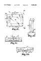
- FIG. 1shows a printer frame (10) constructed in accordance with the present invention.
- the sides of the frame (10)have elongated, dovetail in cross section, portions (11) so that handles (12), which can contain re-chargeable batteries, are selectively attached to or removed from the frame (10).
- An opening (13)is formed for receiving a printer and an opening (14) is formed for receiving a computer terminal or the like.
- the frame (10)will receive a printer back (17) and a printer top (18) or (19).
- the printer topshave latches (21) thereon and two-inch paper slots (22) thereon, although the printer top (18) could have a four-inch paper slot oriented at 90° with respect to the paper slot (22) shown in FIG. 5.
- the printer top (19)has a terminal display (23) thereon which may be used when the terminal itself does not have a display thereon. Similarly, when the terminal to be used has its own display, then the printer top (18) would be used.
- FIG. 5also shows interchangeable terminal tops (30), which can have a drop-in keyboard (31), top (32) which can have a drop-in keyboard (31), a docking unit (33), which can accept a hand-held terminal (34), a pen-based tote or clipboard-type device (35), a device (36) with magnetic card reader (52) and a drop-in keyboard (38) with display (39), a touch-screen device (41) and a top (42) for plugging in a standard computer (43) such as a Hewlett-Packard 95XL, or the like. All of these tops (30), (32), (33), (35), (36), (41) and (42) can all be plugged into the terminal bottom (16), for example.
- a standard computersuch as a Hewlett-Packard 95XL, or the like. All of these tops (30), (32), (33), (35), (36), (41) and (42) can all be plugged into the terminal bottom (16), for example.
- the frame (10) having handles (12) with re-chargeable batteries disposed thereinis pivotally attached to a bottom (16) of a terminal (30) with a touch screen.
- Threaded fasteners (20)achieve the pivotal attachment to frame (10) and are threadably attached to the bottom (16) through the openings in the frame (10) which are shown in FIG. 1.
- printer bottom (17)is attached to the frame (10) and referring back to FIG. 6, it is noted that the top (18) is also attached to the frame (10). This permits two-inch paper to be emitted from slot (22) and the plate (18) is held in place by a latch (21) as discussed above.
- the usercan move the printer to the dashed line position shown in FIG. 7 while leaving the terminal (30) in the position shown in solid lines in FIG. 16.
- Thispermits the user to put one hand between the terminal (30) and the printer (18), i.e., through opening (14). In this way, the user can merely hold the terminal (30) with the printer hanging down.
- the belt loop device (70) shown in FIG. 17can be used wherein the hooks (71) would go around the blank portion of threaded fasteners (20) between the head or handle thereof and the printer frame (10). It would also be desirable, during such use, for the printer to be oriented so that the paper (50) exits away from the person's body rather than toward it, whereby when viewing the device in FIG. 7 orientation with the printer extending down, the person would be on the left of the device with the person's belt (72) having the belt loop device (70) attached thereto. If the printer and terminal shown in FIG.
- the printerwould be oriented such that the paper tape (50) would extend downwardly and the terminal having bottom (16) thereon would then merely be positioned so that it is in clear view of the user.
- the frame (10)has a printer top (19) with the display (23) thereon and a drop-in keyboard (31).
- this drop-in keyboard (31)can have the keys oriented in the direction shown or they can be oriented 90° with respect thereto, depending upon the customer's desires.
- a magnetic card reader (52)is attached to the terminal (32) for reading credit cards (53) or the like by passing the credit card (53) through slot (54) in the magnetic card reader (52).
- the FIG. 8 structurecan be oriented in any of the positions shown in FIG. 7, and of course, any position in between those positions shown in FIG. 7.
- the FIG. 8 drop-in keyboard (31)uses hard keys (55) rather than a touch screen as is shown in FIG. 14.
- the frame (10)also has a top (19) with a display (23), but a docking unit (33) is rotatably attached thereto by threaded fasteners (20).
- This docking unithas a hand-held terminal (34) which snaps into place and automatically plugs into the printer when it is snapped into the slot in docking unit (33).
- This terminal (34)can be one like the Norand Model 1600, Model 1100 or Model 1000.
- the terminal (34)also has a display (57) so that the display (23) is somewhat of a duplication and the top (19) could be replaced by top (18) if desired; or if the terminal (34) does not have a display like (57), then the printer top (19) could be used instead.
- FIG. 10shows a typical orientation of the frame (10) with respect to the docking unit (33), for example if it were used on a desk or laying on a seat of a van or the like.
- the devicecan be hand-held, it can be disposed on a belt as shown in FIG. 17, or it could have a shoulder strap or the like.
- FIG. 16it could also be attached to a van by a bracket (65) having hooks (66) attached thereto and openings (67) for receiving fasteners which would go into the wall of a van or the like.
- the terminal (34)can be removed and used in the many conventional ways that such terminals are used, and when the printing capability is desired, it can be reinserted into the docking unit (34) as shown.
- the frame (10)has printer top (18) attached thereto and a top (36) is attached to the bottom (16), which is, in turn, rotatably attached by threaded fasteners (20) to the frame (10).
- a magnetic card reader (52)is also attached to the top (36) for reading credit cards (53).
- a pen-based tote board device (35)has a screen (61) thereon and a pen (62) disposed in a slot (63) having enlarged opening (64) on each end thereof.
- a pen-like device (62)By pushing down on one end of the pen-like device (62), it will be tipped up to the dashed line position shown in FIG. 18 and can be removed to use on the screen (61).
- This manual way of entering information into the terminal (16)permits the device to be arm holdable, hand holdable and permits use for either left-handed or right-handed people.
- Buttons (59) on each side thereofcan be used for shift functions or to bring up programs or the like and can be soft-labeled to add versatility to conform to what the customer desires.
- the devicecan be hand-held in the position shown in solid lines in FIG. 13 by one arm, while writing with the other arm of the user, or if the device is to be used on a desk or other surface like a desk, the tote board (35) can be tilted up to the dashed line position shown in FIG. 13. If it is desired to remove the tote board device (35) from the printer, the terminal can be removed from the printer and used as a tote board-type device and then reattached to the printer when printing capability is desired.
- the frame (10)has a top (18) attached thereto and a touch-screen display (41) is attached to the terminal bottom (16) shown in FIG. 5.
- the touch-screen device (41)is programmed so that by pushing one of the buttons (60) on each side of the touch-screen, the display will be oriented in one orientation or by pushing another one of buttons (60) in an orientation 90° from the first said orientation whereby if a person desires to use the device on a desk, attached to a van either at a low position or a high position, the display would typically be readable from the position shown in FIG. 14 where the letters and numbers would be upright. However, if it is desired to carry the device around, for example in the FIG.
- the printer frame (10)has a top (42) attached to the bottom (16) shown in FIG. 5 with an adapter plate for automatically plugging in a computer (43), such as a Hewlett-Packard 95XL or the like, having a pivoted lid (44) with a display (45) therein. Since the computer (43) has its own display (45), printer top (18) would be utilized therewith. Of course, the computer (43) can be removed and used independently, or when it is desired to have printer capability, it would be plugged in in the position shown in FIG. 15, into top (42) and bottom (16).
- a computersuch as a Hewlett-Packard 95XL or the like
- FIGS. 19-22show a pen-based terminal (110) which is another embodiment of the pen-based device (35) shown in FIGS. 5, 12 and 13.
- FIGS. 23-25show a docking system (130) for use in conjunction with terminal (110).
- the docking system (130)is another embodiment of the dock (33) shown in FIGS. 5, 9 and 10. It is to be understood that the pen-based terminal (110) could be pivotally attached to the frame (10) (FIG. 1), or the pen-based terminal (110) could be received in the docking system (130) which could be pivotally attached to the frame (10) in a manner similar to that illustrated in FIGS. 12-13 and 9-10.
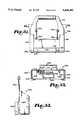
- the pen-based terminal (110)includes a front panel (111) having a number of function keys (112) and indicator lights (113).
- a display (114)extends over a large area of the front panel (111).
- a light pen clip (115)is carried on the top edge of the terminal (110) to receive and secure a light pen (116) in position when not in use to input data.
- a hand strap (117)extends from the top edge, over the back of the housing, then to the bottom edge of the terminal (110).
- a battery cover (118)encloses a section of the back of the housing that carries a rechargeable battery (not shown).
- the vehicle mount (150)has a base (151) that carries a connector (152) and a pair of locator pins (153) that matingly engage a connector (145) and locator openings (146) of a portable dock (140).
- the base (151)houses a transition cable assembly (154) that operably interconnects the connector (152) to a power cable (155) and data cable (156) that extend from the base (151).
- Side panels (157)extend up from each side of the base (151) and pivotally attach to a U-shaped bracket (158) attached to a vehicle (170).
- An arcuate slot (159) in each of the upwardly extending arms of the bracket (158)receives a threaded rod (161) extending from each of the side panels (157).
- a locking wheel (162)is attached to the portion of each rod (161) extending out from the arms of the bracket (158).
- the bracket (158)is typically mounted in the delivery vehicle (170), it is understood that it could likewise be located in a home office, or even a depot environment with multi-dock capability.
- the vehicle mount (150)could, for example, be configured to quickly detach from the bracket (158) and be used in a home office so that only one set of charge control systems, indicators, etc. would be required.
- the vehicle mount (150)is pivotally movable through the range of the arcuate slot (159) to conveniently position the docking system (130) for the user. Once positioned as desired, the locking wheel (162) is tightened to secure the docking system (130) in position.
- the vehicle mount (150)selectively receives the portable dock (140) which in turn selectively receives the pen-based terminal (110).
- the pen-based terminal (110)is operably connected to both the power cable (155) and the data cable (156) through a connector (121) of adapter (120), the connector (145) of the portable dock (140), and the connector (152) of the vehicle mount (150). Attachment to alternative peripheral devices for processing information from and inputing information through the pen-based terminal (110) is illustrated in the schematics of FIGS. 27-30.
- a connector (123)is positioned on the adaptor and the docking system (130) is configured so that the scanner and DEX cables may remain connected to the pen-based terminal (110) when the terminal (110) is positioned in the portable dock (140).
- the charging systemdefaults to charge the battery in the terminal (110) first, and then to charge a spare battery (148) in the portable dock (140).
- FIGS. 31-33show an alternate embodiment of the portable dock (140) shown in FIGS. 23-26.
- FIGS. 31-33show a portable dock (240) having a base (241) that carries a guide (242) and a connector (243) that matingly receive a tab (122) the connector (121) of the terminal (110).
- Open channel members (244)extend up from each side of the base (241) to selectively receive the pen-based terminal (110).
- a connector (245) and locator openings (246)are carried on the underside of the base (241).
- a handle (247)extends up from and is inclined back from the rear of the channel members (244).
- a spare battery charge station (248)extends between the channel members (244) at the rear of the base (241).
- Indicator LEDS (249)are visible from the front of the base (241).
- each of the channel members (244)carries vertically aligned roller guides (250) disposed to contact the rear surface of the pen-based terminal (110).
- the central portion of each of the channel members (244)carries vertically aligned roller guides (260) disposed to contact the lateral edges of the terminal (110).
- the roller guides (250 and 260)facilitate the insertion and removal of the terminal (110) from the portable dock (240).
Landscapes
- Engineering & Computer Science (AREA)
- Physics & Mathematics (AREA)
- Theoretical Computer Science (AREA)
- Electromagnetism (AREA)
- General Physics & Mathematics (AREA)
- Health & Medical Sciences (AREA)
- Artificial Intelligence (AREA)
- Computer Vision & Pattern Recognition (AREA)
- General Health & Medical Sciences (AREA)
- Toxicology (AREA)
- Computer Networks & Wireless Communication (AREA)
- Signal Processing (AREA)
- General Engineering & Computer Science (AREA)
- Computer Hardware Design (AREA)
- Human Computer Interaction (AREA)
- Mechanical Engineering (AREA)
- Quality & Reliability (AREA)
- Business, Economics & Management (AREA)
- Microelectronics & Electronic Packaging (AREA)
- Accounting & Taxation (AREA)
- Strategic Management (AREA)
- General Business, Economics & Management (AREA)
- Accessory Devices And Overall Control Thereof (AREA)
- Casings For Electric Apparatus (AREA)
Abstract
Description
Claims (4)
Priority Applications (3)
| Application Number | Priority Date | Filing Date | Title |
|---|---|---|---|
| US08/275,884US5408382A (en) | 1992-01-10 | 1994-07-15 | Terminal and docking mechanism with open channel members and guide rollers |
| US08/423,239US5544010A (en) | 1990-07-25 | 1995-04-17 | Portable electronic device docking system |
| US08/645,980US5644471A (en) | 1990-07-25 | 1996-05-14 | Portable dock for a portable electronic device |
Applications Claiming Priority (4)
| Application Number | Priority Date | Filing Date | Title |
|---|---|---|---|
| US81876192A | 1992-01-10 | 1992-01-10 | |
| US88045292A | 1992-05-08 | 1992-05-08 | |
| US95887392A | 1992-10-08 | 1992-10-08 | |
| US08/275,884US5408382A (en) | 1992-01-10 | 1994-07-15 | Terminal and docking mechanism with open channel members and guide rollers |
Related Parent Applications (1)
| Application Number | Title | Priority Date | Filing Date |
|---|---|---|---|
| US95887392AContinuation | 1990-07-25 | 1992-10-08 |
Related Child Applications (1)
| Application Number | Title | Priority Date | Filing Date |
|---|---|---|---|
| US08/423,239DivisionUS5544010A (en) | 1990-07-25 | 1995-04-17 | Portable electronic device docking system |
Publications (1)
| Publication Number | Publication Date |
|---|---|
| US5408382Atrue US5408382A (en) | 1995-04-18 |
Family
ID=27420130
Family Applications (3)
| Application Number | Title | Priority Date | Filing Date |
|---|---|---|---|
| US08/275,884Expired - LifetimeUS5408382A (en) | 1990-07-25 | 1994-07-15 | Terminal and docking mechanism with open channel members and guide rollers |
| US08/423,239Expired - LifetimeUS5544010A (en) | 1990-07-25 | 1995-04-17 | Portable electronic device docking system |
| US08/645,980Expired - LifetimeUS5644471A (en) | 1990-07-25 | 1996-05-14 | Portable dock for a portable electronic device |
Family Applications After (2)
| Application Number | Title | Priority Date | Filing Date |
|---|---|---|---|
| US08/423,239Expired - LifetimeUS5544010A (en) | 1990-07-25 | 1995-04-17 | Portable electronic device docking system |
| US08/645,980Expired - LifetimeUS5644471A (en) | 1990-07-25 | 1996-05-14 | Portable dock for a portable electronic device |
Country Status (1)
| Country | Link |
|---|---|
| US (3) | US5408382A (en) |
Cited By (80)
| Publication number | Priority date | Publication date | Assignee | Title |
|---|---|---|---|---|
| WO1996004600A1 (en)* | 1994-08-03 | 1996-02-15 | Elonex Technologies, Inc. | Micro personal digital assistant |
| US5522089A (en)* | 1993-05-07 | 1996-05-28 | Cordata, Inc. | Personal digital assistant module adapted for initiating telephone communications through DTMF dialing |
| US5544011A (en)* | 1994-01-14 | 1996-08-06 | Apple Computer, Inc. | Bracket and module assembly for a portable personal computer |
| US5627727A (en)* | 1994-09-02 | 1997-05-06 | Ncr Corporation | Portable computer assembly and method |
| EP0773492A1 (en)* | 1995-11-07 | 1997-05-14 | Wagner Fördertechnik GmbH & Co KG | Housing for data processing apparatus |
| US5687060A (en)* | 1996-06-17 | 1997-11-11 | Compaq Computer Corporation | Vertically oriented docking station apparatus for a portable computer |
| EP0814397A3 (en)* | 1996-06-17 | 1998-04-29 | CLAAS KGaA | Portable board computer system with control units for working machines |
| US5751548A (en)* | 1996-05-13 | 1998-05-12 | International Business Machines Corporation | Docking station for a portable computer providing rotational movement of the computer's viewable screen in three different planes |
| US5754397A (en)* | 1997-01-21 | 1998-05-19 | Dell Computer Corporation | Docking connector with height adjustment in a computer system |
| US5768100A (en)* | 1996-03-01 | 1998-06-16 | Compaq Computer Corporation | Modular computer having configuration-specific performance characteristics |
| US5838539A (en)* | 1995-11-08 | 1998-11-17 | Electronics Accessory Specialists International | Docking module for portable computers |
| US5859762A (en)* | 1996-05-13 | 1999-01-12 | International Business Machines Corporation | Docking station for portable computers |
| WO2000010878A3 (en)* | 1998-08-21 | 2000-06-02 | Trekware Corp | Keyboard/case for handheld computers |
| US6081261A (en)* | 1995-11-01 | 2000-06-27 | Ricoh Corporation | Manual entry interactive paper and electronic document handling and processing system |
| US6157958A (en)* | 1998-07-31 | 2000-12-05 | Qubit, Llc | Modular tablet computer system |
| US6181329B1 (en) | 1997-12-23 | 2001-01-30 | Ricoh Company, Ltd. | Method and apparatus for tracking a hand-held writing instrument with multiple sensors that are calibrated by placing the writing instrument in predetermined positions with respect to the writing surface |
| US6188392B1 (en) | 1997-06-30 | 2001-02-13 | Intel Corporation | Electronic pen device |
| US6201903B1 (en) | 1997-09-30 | 2001-03-13 | Ricoh Company, Ltd. | Method and apparatus for pen-based faxing |
| US6266539B1 (en) | 1998-06-12 | 2001-07-24 | Cisco Technology, Inc. | Telephone docking station for personal digital assistant |
| US6282082B1 (en) | 1998-07-31 | 2001-08-28 | Qubit, Llc | Case for a modular tablet computer system |
| US20040147295A1 (en)* | 1997-12-12 | 2004-07-29 | Joseph Domes | Ruggedized tradesworkers radio |
| US20040224765A1 (en)* | 2003-05-09 | 2004-11-11 | Microsoft Corporation | Text input device and adapter mechanism |
| US20050078461A1 (en)* | 2003-10-08 | 2005-04-14 | Dobbs Robert William | Card guide that comprises card guide portions that serve to guide a circuit board into a chassis |
| US20060022097A1 (en)* | 2004-07-29 | 2006-02-02 | Homer Steven S | Computer docking system |
| US20060024107A1 (en)* | 2004-07-29 | 2006-02-02 | Zih Corp. | Docking station and associated method for docking a portable printer |
| US20060028528A1 (en)* | 2004-07-29 | 2006-02-09 | Zih Corp. | Interchangeable module for a portable printer and system for operating the same |
| USD516562S1 (en) | 2004-09-22 | 2006-03-07 | Hewlett-Packard Development Company, L.P. | Computer docking station |
| US20060061958A1 (en)* | 2004-09-17 | 2006-03-23 | Mark Solomon | Portable computer docking station |
| US20060289654A1 (en)* | 2005-06-27 | 2006-12-28 | Robinson Michael D | Method and system for linking a wireless hand held optical reader with a base unit or other wireless device |
| US7251318B1 (en) | 1994-01-05 | 2007-07-31 | Intellect Wireless Inc. | Method and apparatus for improved personal communication devices and systems |
| US7257210B1 (en) | 1994-01-05 | 2007-08-14 | Intellect Wireless Inc. | Picture phone with caller id |
| US20070284441A1 (en)* | 2006-06-13 | 2007-12-13 | Joseph Walczyk | Method and apparatus for uniquely associating a bar code reading terminal to a cash register in a retail store network |
| US20070288251A1 (en)* | 2005-06-09 | 2007-12-13 | Whirlpool Corporation | Method of providing product demonstrations |
| US20070298405A1 (en)* | 2006-06-08 | 2007-12-27 | Whirlpool Corporation | Product demonstration system |
| US20080100695A1 (en)* | 2006-06-08 | 2008-05-01 | Whirlpool Corporation | Product Demonstration System and Method |
| US20080109243A1 (en)* | 2005-06-09 | 2008-05-08 | Whirlpool Corporation | Product Demonstration System and Method |
| US20080109310A1 (en)* | 2005-06-09 | 2008-05-08 | Whirlpool Corporation | Product Demonstration System and Method |
| US20080143489A1 (en)* | 2005-06-09 | 2008-06-19 | Whirlpool Corporation | Smart coupling device |
| US20080164796A1 (en)* | 2007-01-04 | 2008-07-10 | Whirlpool Corporation | A Dispenser With a Service Interface for a Consumer Electronic Device |
| US20080164758A1 (en)* | 2007-01-04 | 2008-07-10 | Mccoy Richard A | Electrical accessory charging compartment for a cabinet and retrofit components therefor |
| US20080165282A1 (en)* | 2007-01-04 | 2008-07-10 | Whirlpool Corporation | Appliance Door With a Service Interface |
| US20080164225A1 (en)* | 2007-01-04 | 2008-07-10 | Whirlpool Corporation | An Adapter for Coupling a Host and a Consumer Electronic Device Having Dissimilar Standardized Interfaces |
| US20080164224A1 (en)* | 2007-01-04 | 2008-07-10 | Whirlpool Corporation | System for connecting mechnically dissimilar consumer electronic devices to anadaptor or a host |
| US20080164226A1 (en)* | 2007-01-04 | 2008-07-10 | Whirlpool Corporation | Alternative Hosts for Multiple Adapters and Multiple Consumer Electronic Devices |
| US20080165998A1 (en)* | 2007-01-04 | 2008-07-10 | Whirlpool Corporation | Acoustic chamber as part of adapter or appliance |
| US20080168205A1 (en)* | 2007-01-04 | 2008-07-10 | Whirlpool Corporation | Functional Adapter for a Consumer Electronic Device |
| US20080166895A1 (en)* | 2007-01-04 | 2008-07-10 | Whirlpool Corporation | System for Supplying Service From an Appliance To Multiple Consumer Electronic Devices |
| US20080165505A1 (en)* | 2007-01-04 | 2008-07-10 | Whirlpool Corporation | Door With a Service Interface On An Edge |
| US20080166915A1 (en)* | 2007-01-04 | 2008-07-10 | Whirlpool Corporation | Appliance With an Adapter to Simultaneously Couple Multiple Consumer Electronic Devices |
| US20080165509A1 (en)* | 2007-01-04 | 2008-07-10 | Whirlpool Corporation | Host With Multiple Adapters for Coupling Consumer Electronic Devices |
| USD575786S1 (en)* | 2005-10-24 | 2008-08-26 | Hewlett-Packard Development Company, L.P. | Computer docking station |
| US20080287009A1 (en)* | 2007-01-04 | 2008-11-20 | Whirlpool Corporation | Adapter with an access panel for an electronic device |
| US7483417B2 (en) | 1996-04-18 | 2009-01-27 | Verizon Services Corp. | Telephony communication via varied redundant networks |
| US7664097B2 (en) | 1996-04-18 | 2010-02-16 | Verizon Services Corp. | Telephone service via networking |
| US7798865B2 (en) | 2007-01-04 | 2010-09-21 | Whirlpool Corporation | Service supply module and adapter for a consumer electronic device |
| US7813332B1 (en) | 1997-03-19 | 2010-10-12 | Verizon Services Corp. | Voice call alternative routing through PSTN and internet networks |
| US7817619B1 (en) | 1996-12-18 | 2010-10-19 | Verizon Services Corp. | Internet long distance telephone service |
| US7830860B2 (en) | 1997-03-11 | 2010-11-09 | Verizon Services Corp. | Packet data network voice call quality monitoring |
| US7835344B1 (en) | 1997-03-19 | 2010-11-16 | Verizon Services Corp. | Transport of caller identification information through diverse communication networks |
| US7865639B2 (en) | 2007-01-04 | 2011-01-04 | Whirlpool Corporation | Appliance with an electrically adaptive adapter to alternatively couple multiple consumer electronic devices |
| US7869201B2 (en) | 2007-01-04 | 2011-01-11 | Whirlpool Corporation | Host and adapter for selectively positioning a consumer electronic display in visible and concealed orientations |
| US7871300B2 (en) | 2007-01-04 | 2011-01-18 | Whirlpool Corporation | Host with multiple sequential adapters for multiple consumer electronic devices |
| US7948968B2 (en) | 1997-09-16 | 2011-05-24 | Verizon Communications Inc. | Network session management |
| US20110149486A1 (en)* | 2009-12-17 | 2011-06-23 | Askey Computer Corp. | Electronic device carrier |
| US7980088B2 (en) | 2007-01-04 | 2011-07-19 | Whirlpool Corporation | Removable adapter providing a wireless service to removable consumer electronic device |
| US8018716B2 (en) | 2007-01-04 | 2011-09-13 | Whirlpool Corporation | Adapter for docking a consumer electronic device in discrete orientations |
| US20110267773A1 (en)* | 2010-04-05 | 2011-11-03 | Macfarlane Scott | Holders for tablet computers |
| USD662502S1 (en)* | 2011-02-15 | 2012-06-26 | Data Ltd., Inc. | Tablet computer cradle |
| US20120170203A1 (en)* | 2011-01-03 | 2012-07-05 | Ems Technologies, Inc. | Quick Mount System for Computer Terminal |
| USD668657S1 (en) | 2010-09-01 | 2012-10-09 | Data Ltd., Inc. | Tablet computer cradle |
| US20120275092A1 (en)* | 2011-04-26 | 2012-11-01 | Hon Hai Precision Industry Co., Ltd. | Docking station and electronic device |
| US20120275107A1 (en)* | 2011-04-28 | 2012-11-01 | Kabushiki Kaisha Toshiba | Docking station and electronic device |
| USD680118S1 (en)* | 2011-09-09 | 2013-04-16 | Aktieselskabet af 18. Juli 2011 | Docking station |
| US8493326B2 (en) | 2003-05-09 | 2013-07-23 | Microsoft Corporation | Controller with removably attachable text input device |
| US8794579B2 (en) | 2005-06-03 | 2014-08-05 | Steelcase, Inc. | Support arm assembly |
| US8938062B2 (en) | 1995-12-11 | 2015-01-20 | Comcast Ip Holdings I, Llc | Method for accessing service resource items that are for use in a telecommunications system |
| US9191505B2 (en) | 2009-05-28 | 2015-11-17 | Comcast Cable Communications, Llc | Stateful home phone service |
| US20180234125A1 (en)* | 2017-02-16 | 2018-08-16 | Datron World Communications, Inc. | Mobile mount for simultaneous portable radio and spare battery charging and method for the same |
| US20180322494A1 (en)* | 2017-05-04 | 2018-11-08 | Se-Kure Controls, Inc. | Security system for epos terminal |
| TWI693847B (en)* | 2017-02-16 | 2020-05-11 | 美商達創世界通訊公司 | Mobile mount for simultaneous portable radio and spare battery charging and method for the same |
Families Citing this family (50)
| Publication number | Priority date | Publication date | Assignee | Title |
|---|---|---|---|---|
| US5408382A (en)* | 1992-01-10 | 1995-04-18 | Norand Corporation | Terminal and docking mechanism with open channel members and guide rollers |
| WO1995019030A1 (en)* | 1994-01-05 | 1995-07-13 | Pois, Inc. | Apparatus and method for a personal onboard information system |
| US5768163A (en)* | 1996-04-15 | 1998-06-16 | Hewlett-Packard | Versatile attachment of handheld devices to a host computing system |
| US5946186A (en)* | 1996-08-30 | 1999-08-31 | Texas Instruments Incorporated | Latch apparatus and attachment system |
| US6101087A (en)* | 1997-06-19 | 2000-08-08 | Xplore Technologies, Inc. | Portable pen-based computer and auxiliary unit for use with a vehicular docking station |
| JP3200585B2 (en)* | 1998-02-10 | 2001-08-20 | 富士通株式会社 | Mobile phones and information communication adapters |
| US6068496A (en)* | 1998-03-09 | 2000-05-30 | 3Com Corporation | Sliding door for a dock port |
| CA2246139A1 (en)* | 1998-08-26 | 2000-02-26 | Computer Security Devices Inc. | Laptop computer security device |
| US6504710B2 (en)* | 1998-11-27 | 2003-01-07 | Xplore Technologies Corp. | Method of interconnecting of a hand-held auxiliary unit, a portable computer and a peripheral device |
| US6330427B1 (en) | 1999-09-08 | 2001-12-11 | Joel B. Tabachnik | Talking novelty device with book |
| US20020065902A1 (en)* | 2000-09-05 | 2002-05-30 | Janik Craig M. | Webpad and method for using the same |
| US20020078248A1 (en)* | 2000-09-05 | 2002-06-20 | Janik Craig M. | Adapter module for a personal digital assistant and method for using the same |
| US20020065927A1 (en) | 2000-09-05 | 2002-05-30 | Janik Craig M. | Webpad and method for using the same |
| US20060031550A1 (en)* | 2000-09-05 | 2006-02-09 | Universal Electronics Inc. | Webpad adapted to communicate using wide area and local area communication channels |
| JP4403218B2 (en)* | 2000-10-19 | 2010-01-27 | レノボ シンガポール プライヴェート リミテッド | Expansion connector device |
| US6549399B2 (en) | 2000-12-15 | 2003-04-15 | Palm, Inc. | Door mechanism for handheld computer |
| EP1266834A1 (en)* | 2001-06-15 | 2002-12-18 | Pace Micro Technology PLC | Package and method of packaging |
| US6985579B2 (en)* | 2001-09-26 | 2006-01-10 | Siemens Communications, Inc. | Portable communication device having an output unit positionable and rotatable with respect to an input unit |
| US6916128B1 (en)* | 2001-12-07 | 2005-07-12 | Zih Corp. | Printer attachable to various models and types of portable devices and terminals for operation therewith |
| US20030154291A1 (en)* | 2002-02-05 | 2003-08-14 | International Business Machines Corporation | Mobile modular computer |
| GB2388270A (en)* | 2002-05-03 | 2003-11-05 | Mitel Knowledge Corp | Telephone having replaceable cradle for a PDA |
| US7529519B2 (en)* | 2003-02-10 | 2009-05-05 | Leapfrog Enterprises, Inc. | Interactive handheld educational apparatus with stylus |
| US20050235326A1 (en)* | 2003-11-07 | 2005-10-20 | Vitito Christopher J | Vehicle entertainment system |
| US7604273B2 (en)* | 2003-11-07 | 2009-10-20 | Vitito Christopher J | Vehicle entertainment system |
| US20050099547A1 (en)* | 2003-11-07 | 2005-05-12 | Vitito Christopher J. | Automobile entertainment system |
| US20060070103A1 (en)* | 2003-11-07 | 2006-03-30 | Vitito Christopher J | Vehicle entertainment system |
| US20050235327A1 (en)* | 2003-11-07 | 2005-10-20 | Vitito Christopher J | Vehicle entertainment system |
| US20050223406A1 (en)* | 2003-11-07 | 2005-10-06 | Vitito Christopher J | Vehicle entertainment system including a detachable video system with a hard drive based video source |
| US8780282B2 (en)* | 2003-11-07 | 2014-07-15 | Voxx International Corporation | Vehicle entertainment system |
| TWI251186B (en)* | 2004-03-12 | 2006-03-11 | Benq Corp | Liquid crystal display and coupling assembly thereof |
| US20050270731A1 (en)* | 2004-06-07 | 2005-12-08 | Memphis-Zhihong Yin | Computer docking system |
| US7095608B2 (en)* | 2004-08-12 | 2006-08-22 | Audiovox Corporation | Video display mounting system and method |
| US8070224B2 (en)* | 2005-04-20 | 2011-12-06 | Audiovox Corporation | Vehicle entertainment system incorporated within the armrest/console of a vehicle |
| US7857382B2 (en)* | 2005-04-20 | 2010-12-28 | Audiovox Corporation | Detachable vehicle entertainment system for the armrest/console of a vehicle |
| US8120716B2 (en)* | 2005-06-16 | 2012-02-21 | Audiovox Corporation | Vehicle entertainment system including monitor for rear view enhancement |
| WO2006138446A2 (en)* | 2005-06-16 | 2006-12-28 | Vitito Christopher J | Vehicle entertainment system |
| US20080298875A1 (en)* | 2007-06-01 | 2008-12-04 | Intermec Technologies Corporation | Modular workboard thermal printer system |
| US8145821B2 (en)* | 2008-05-20 | 2012-03-27 | Honeywell International Inc. | Docking station for portable electronic devices |
| US20100177473A1 (en)* | 2008-07-31 | 2010-07-15 | Advanpos Technology Co. Ltd. | Computer device |
| US8240631B2 (en)* | 2009-06-04 | 2012-08-14 | Honeywell International Inc. | Apparatus for controlling liquid in a cup holder |
| USD626128S1 (en)* | 2009-12-04 | 2010-10-26 | Visioneer, Inc. | Stackable scanner docking station |
| TWI386582B (en)* | 2010-06-10 | 2013-02-21 | Giga Byte Tech Co Ltd | Computer system and base structure thereof |
| TWI537704B (en)* | 2010-06-10 | 2016-06-11 | 技嘉科技股份有限公司 | Computer system |
| US8619416B2 (en)* | 2011-10-11 | 2013-12-31 | Hewlett-Packard Development Company, L.P. | Dual-orientation docking apparatus |
| US9169964B2 (en)* | 2012-02-21 | 2015-10-27 | L-3 Communications Avionics Systems, Inc. | Retention mechanism and method for removeably supporting a portable flight controller |
| CN202563381U (en)* | 2012-03-26 | 2012-11-28 | 基诺·安度坦 | Tablet case with built-in printer |
| US9001511B2 (en) | 2012-10-19 | 2015-04-07 | 2236008 Ontario Inc. | Portable docking station for portable electronic device |
| CN203481906U (en)* | 2012-12-04 | 2014-03-12 | MiPwr有限责任公司 | Mobile communications equipment kit and coat device thereof |
| DE202020103384U1 (en)* | 2020-06-12 | 2020-07-07 | Siemens Healthcare Gmbh | Docking station for a tablet computer unit |
| DE102020208173B4 (en) | 2020-06-30 | 2022-11-03 | Siemens Healthcare Gmbh | Arrangement with a tablet computer unit and a housing part of a medical imaging device |
Citations (7)
| Publication number | Priority date | Publication date | Assignee | Title |
|---|---|---|---|---|
| US4345147A (en)* | 1980-11-14 | 1982-08-17 | International Telephone And Telegraph Corporation | Vehicle mounted mobile business data handling system |
| US4794381A (en)* | 1985-09-09 | 1988-12-27 | Sharp Kabushiki Kaisha | Electronic apparatus |
| US5041924A (en)* | 1988-11-30 | 1991-08-20 | Quantum Corporation | Removable and transportable hard disk subsystem |
| US5105335A (en)* | 1988-04-28 | 1992-04-14 | Kabushiki Kaisha Toshiba | Hard case for housing and carrying electronic devices |
| US5133076A (en)* | 1989-06-12 | 1992-07-21 | Grid Systems Corporation | Hand held computer |
| US5209583A (en)* | 1992-04-01 | 1993-05-11 | Telxon Corporation | Compact printer for portable computer |
| US5290178A (en)* | 1992-03-10 | 1994-03-01 | Ma Hsi K | Docking station apparatus for portable computer |
Family Cites Families (5)
| Publication number | Priority date | Publication date | Assignee | Title |
|---|---|---|---|---|
| US4760375A (en)* | 1983-10-28 | 1988-07-26 | Josef Stecker | Data transmission cable |
| US5030128A (en)* | 1989-03-06 | 1991-07-09 | Dynabook Technologies Corporation | Docking module |
| US5408382A (en)* | 1992-01-10 | 1995-04-18 | Norand Corporation | Terminal and docking mechanism with open channel members and guide rollers |
| US5227953A (en)* | 1991-10-18 | 1993-07-13 | Hewlett-Packard Company | Apparatus for retaining and electrically interconnecting multiple devices |
| US5186646A (en)* | 1992-01-16 | 1993-02-16 | Pederson William A | Connector device for computers |
- 1994
- 1994-07-15USUS08/275,884patent/US5408382A/ennot_activeExpired - Lifetime
- 1995
- 1995-04-17USUS08/423,239patent/US5544010A/ennot_activeExpired - Lifetime
- 1996
- 1996-05-14USUS08/645,980patent/US5644471A/ennot_activeExpired - Lifetime
Patent Citations (7)
| Publication number | Priority date | Publication date | Assignee | Title |
|---|---|---|---|---|
| US4345147A (en)* | 1980-11-14 | 1982-08-17 | International Telephone And Telegraph Corporation | Vehicle mounted mobile business data handling system |
| US4794381A (en)* | 1985-09-09 | 1988-12-27 | Sharp Kabushiki Kaisha | Electronic apparatus |
| US5105335A (en)* | 1988-04-28 | 1992-04-14 | Kabushiki Kaisha Toshiba | Hard case for housing and carrying electronic devices |
| US5041924A (en)* | 1988-11-30 | 1991-08-20 | Quantum Corporation | Removable and transportable hard disk subsystem |
| US5133076A (en)* | 1989-06-12 | 1992-07-21 | Grid Systems Corporation | Hand held computer |
| US5290178A (en)* | 1992-03-10 | 1994-03-01 | Ma Hsi K | Docking station apparatus for portable computer |
| US5209583A (en)* | 1992-04-01 | 1993-05-11 | Telxon Corporation | Compact printer for portable computer |
Cited By (155)
| Publication number | Priority date | Publication date | Assignee | Title |
|---|---|---|---|---|
| US5522089A (en)* | 1993-05-07 | 1996-05-28 | Cordata, Inc. | Personal digital assistant module adapted for initiating telephone communications through DTMF dialing |
| US7251318B1 (en) | 1994-01-05 | 2007-07-31 | Intellect Wireless Inc. | Method and apparatus for improved personal communication devices and systems |
| US7310416B1 (en) | 1994-01-05 | 2007-12-18 | Intellect Wireless Inc. | Method and apparatus for improved personal communication devices and systems |
| US7257210B1 (en) | 1994-01-05 | 2007-08-14 | Intellect Wireless Inc. | Picture phone with caller id |
| US7254223B1 (en) | 1994-01-05 | 2007-08-07 | Intellect Wireless Inc. | Method and apparatus for improved personal communication devices and systems |
| US7286658B1 (en) | 1994-01-05 | 2007-10-23 | Intellect Wireless Inc. | Method and apparatus for improved personal communication devices and systems |
| US7308088B1 (en) | 1994-01-05 | 2007-12-11 | Intellect Wireless, Inc. | Method and apparatus for improved personal communication devices and systems |
| US7266186B1 (en) | 1994-01-05 | 2007-09-04 | Intellect Wireless Inc. | Method and apparatus for improved paging receiver and system |
| US7305076B1 (en) | 1994-01-05 | 2007-12-04 | Intellect Wireless Inc. | Method and apparatus for improved paging receiver and system |
| US7349532B2 (en) | 1994-01-05 | 2008-03-25 | Intellect Wireless Inc. | Picture and video message center system |
| US7426264B1 (en) | 1994-01-05 | 2008-09-16 | Henderson Daniel A | Method and apparatus for improved personal communication devices and systems |
| US7454000B1 (en) | 1994-01-05 | 2008-11-18 | Intellect Wireless, Inc. | Method and apparatus for improved personal communication devices and systems |
| US5544011A (en)* | 1994-01-14 | 1996-08-06 | Apple Computer, Inc. | Bracket and module assembly for a portable personal computer |
| WO1996004600A1 (en)* | 1994-08-03 | 1996-02-15 | Elonex Technologies, Inc. | Micro personal digital assistant |
| US5627727A (en)* | 1994-09-02 | 1997-05-06 | Ncr Corporation | Portable computer assembly and method |
| US6081261A (en)* | 1995-11-01 | 2000-06-27 | Ricoh Corporation | Manual entry interactive paper and electronic document handling and processing system |
| EP0773492A1 (en)* | 1995-11-07 | 1997-05-14 | Wagner Fördertechnik GmbH & Co KG | Housing for data processing apparatus |
| US5838539A (en)* | 1995-11-08 | 1998-11-17 | Electronics Accessory Specialists International | Docking module for portable computers |
| US8938062B2 (en) | 1995-12-11 | 2015-01-20 | Comcast Ip Holdings I, Llc | Method for accessing service resource items that are for use in a telecommunications system |
| US5768100A (en)* | 1996-03-01 | 1998-06-16 | Compaq Computer Corporation | Modular computer having configuration-specific performance characteristics |
| US6246575B1 (en) | 1996-03-01 | 2001-06-12 | Compaq Computer Corporation | Modular computer |
| US7664097B2 (en) | 1996-04-18 | 2010-02-16 | Verizon Services Corp. | Telephone service via networking |
| US7483417B2 (en) | 1996-04-18 | 2009-01-27 | Verizon Services Corp. | Telephony communication via varied redundant networks |
| US8379531B2 (en) | 1996-04-18 | 2013-02-19 | Verizon Services Corp. | Telephony communication via varied redundant networks |
| US5751548A (en)* | 1996-05-13 | 1998-05-12 | International Business Machines Corporation | Docking station for a portable computer providing rotational movement of the computer's viewable screen in three different planes |
| US5859762A (en)* | 1996-05-13 | 1999-01-12 | International Business Machines Corporation | Docking station for portable computers |
| US5687060A (en)* | 1996-06-17 | 1997-11-11 | Compaq Computer Corporation | Vertically oriented docking station apparatus for a portable computer |
| EP0814397A3 (en)* | 1996-06-17 | 1998-04-29 | CLAAS KGaA | Portable board computer system with control units for working machines |
| US6185094B1 (en) | 1996-06-17 | 2001-02-06 | Compaq Computer Corporation | Vertically oriented docking station apparatus for a portable computer |
| US8553681B2 (en) | 1996-06-26 | 2013-10-08 | Verizon Services Corp. | Telephone service via packet-switched networking |
| US7817619B1 (en) | 1996-12-18 | 2010-10-19 | Verizon Services Corp. | Internet long distance telephone service |
| US5754397A (en)* | 1997-01-21 | 1998-05-19 | Dell Computer Corporation | Docking connector with height adjustment in a computer system |
| US7830860B2 (en) | 1997-03-11 | 2010-11-09 | Verizon Services Corp. | Packet data network voice call quality monitoring |
| US7813332B1 (en) | 1997-03-19 | 2010-10-12 | Verizon Services Corp. | Voice call alternative routing through PSTN and internet networks |
| US7835344B1 (en) | 1997-03-19 | 2010-11-16 | Verizon Services Corp. | Transport of caller identification information through diverse communication networks |
| US6188392B1 (en) | 1997-06-30 | 2001-02-13 | Intel Corporation | Electronic pen device |
| US8976782B1 (en) | 1997-09-16 | 2015-03-10 | Verizon Patent And Licensing Inc. | Network session management for telephony over hybrid networks |
| US7948968B2 (en) | 1997-09-16 | 2011-05-24 | Verizon Communications Inc. | Network session management |
| US9215254B1 (en) | 1997-09-16 | 2015-12-15 | Verizon Patent And Licensing Inc. | Network session management for telephony over hybrid networks |
| US6201903B1 (en) | 1997-09-30 | 2001-03-13 | Ricoh Company, Ltd. | Method and apparatus for pen-based faxing |
| USRE44557E1 (en) | 1997-12-12 | 2013-10-22 | Black & Decker Inc. | Ruggedized tradesworkers radio |
| US7043283B2 (en) | 1997-12-12 | 2006-05-09 | Black & Decker Inc. | Ruggedized tradesworkers radio |
| US20040147295A1 (en)* | 1997-12-12 | 2004-07-29 | Joseph Domes | Ruggedized tradesworkers radio |
| US6181329B1 (en) | 1997-12-23 | 2001-01-30 | Ricoh Company, Ltd. | Method and apparatus for tracking a hand-held writing instrument with multiple sensors that are calibrated by placing the writing instrument in predetermined positions with respect to the writing surface |
| US6492981B1 (en) | 1997-12-23 | 2002-12-10 | Ricoh Company, Ltd. | Calibration of a system for tracking a writing instrument with multiple sensors |
| US6266539B1 (en) | 1998-06-12 | 2001-07-24 | Cisco Technology, Inc. | Telephone docking station for personal digital assistant |
| US6157958A (en)* | 1998-07-31 | 2000-12-05 | Qubit, Llc | Modular tablet computer system |
| US6282082B1 (en) | 1998-07-31 | 2001-08-28 | Qubit, Llc | Case for a modular tablet computer system |
| WO2000010878A3 (en)* | 1998-08-21 | 2000-06-02 | Trekware Corp | Keyboard/case for handheld computers |
| US8493326B2 (en) | 2003-05-09 | 2013-07-23 | Microsoft Corporation | Controller with removably attachable text input device |
| US20040224765A1 (en)* | 2003-05-09 | 2004-11-11 | Microsoft Corporation | Text input device and adapter mechanism |
| US20070268262A1 (en)* | 2003-05-09 | 2007-11-22 | Microsoft Corporation | Text Input Device and Adapter Mechanism |
| US7283125B2 (en)* | 2003-05-09 | 2007-10-16 | Microsoft Corporation | Text input device and adapter mechanism |
| US20050078461A1 (en)* | 2003-10-08 | 2005-04-14 | Dobbs Robert William | Card guide that comprises card guide portions that serve to guide a circuit board into a chassis |
| US6940727B2 (en)* | 2003-10-08 | 2005-09-06 | Hewlett-Packard Development Company, L.P. | Card guide that comprises card guide portions that serve to guide a circuit board into a chassis |
| US20060022097A1 (en)* | 2004-07-29 | 2006-02-02 | Homer Steven S | Computer docking system |
| US20060024107A1 (en)* | 2004-07-29 | 2006-02-02 | Zih Corp. | Docking station and associated method for docking a portable printer |
| US7708240B2 (en) | 2004-07-29 | 2010-05-04 | Hewlett-Packard Development Company, L.P. | Computer docking system |
| US7306386B2 (en) | 2004-07-29 | 2007-12-11 | Zih Corp. | Docking station and associated method for docking a portable printer |
| US20060028528A1 (en)* | 2004-07-29 | 2006-02-09 | Zih Corp. | Interchangeable module for a portable printer and system for operating the same |
| US7502225B2 (en) | 2004-09-17 | 2009-03-10 | Hewlett-Packard Development Company, L.P. | Portable computer docking station |
| US20060061958A1 (en)* | 2004-09-17 | 2006-03-23 | Mark Solomon | Portable computer docking station |
| USD516562S1 (en) | 2004-09-22 | 2006-03-07 | Hewlett-Packard Development Company, L.P. | Computer docking station |
| US8794579B2 (en) | 2005-06-03 | 2014-08-05 | Steelcase, Inc. | Support arm assembly |
| US8676656B2 (en) | 2005-06-09 | 2014-03-18 | Whirlpool Corporation | Method for product demonstration |
| US8250163B2 (en) | 2005-06-09 | 2012-08-21 | Whirlpool Corporation | Smart coupling device |
| US8856036B2 (en) | 2005-06-09 | 2014-10-07 | Whirlpool Corporation | Method of providing product demonstrations |
| US20080143489A1 (en)* | 2005-06-09 | 2008-06-19 | Whirlpool Corporation | Smart coupling device |
| US20080109310A1 (en)* | 2005-06-09 | 2008-05-08 | Whirlpool Corporation | Product Demonstration System and Method |
| US20080109243A1 (en)* | 2005-06-09 | 2008-05-08 | Whirlpool Corporation | Product Demonstration System and Method |
| US8571942B2 (en) | 2005-06-09 | 2013-10-29 | Whirlpool Corporation | Method of product demonstration |
| US20070288251A1 (en)* | 2005-06-09 | 2007-12-13 | Whirlpool Corporation | Method of providing product demonstrations |
| US20060289654A1 (en)* | 2005-06-27 | 2006-12-28 | Robinson Michael D | Method and system for linking a wireless hand held optical reader with a base unit or other wireless device |
| US7556203B2 (en) | 2005-06-27 | 2009-07-07 | Hand Held Products, Inc. | Method and system for linking a wireless hand held optical reader with a base unit or other wireless device |
| USD575786S1 (en)* | 2005-10-24 | 2008-08-26 | Hewlett-Packard Development Company, L.P. | Computer docking station |
| USD598453S1 (en)* | 2005-10-24 | 2009-08-18 | Hewlett-Packard Development Company, L.P. | Computer docking station |
| US8682735B2 (en) | 2006-06-08 | 2014-03-25 | Whirlpool Corporation | Method for product demonstration |
| US20080100695A1 (en)* | 2006-06-08 | 2008-05-01 | Whirlpool Corporation | Product Demonstration System and Method |
| US20070298405A1 (en)* | 2006-06-08 | 2007-12-27 | Whirlpool Corporation | Product demonstration system |
| US8682733B2 (en) | 2006-06-08 | 2014-03-25 | Whirlpool Corporation | System for product demonstration |
| US8688530B2 (en) | 2006-06-08 | 2014-04-01 | Whirlpool Corporation | System for product demonstration |
| US20070284441A1 (en)* | 2006-06-13 | 2007-12-13 | Joseph Walczyk | Method and apparatus for uniquely associating a bar code reading terminal to a cash register in a retail store network |
| US7686216B2 (en) | 2006-06-13 | 2010-03-30 | Hand Held Products, Inc. | Method and apparatus for uniquely associating a bar code reading terminal to a cash register in a retail store network |
| US7869201B2 (en) | 2007-01-04 | 2011-01-11 | Whirlpool Corporation | Host and adapter for selectively positioning a consumer electronic display in visible and concealed orientations |
| US8040666B2 (en) | 2007-01-04 | 2011-10-18 | Whirlpool Corporation | Door with a service interface on an edge |
| US20080164225A1 (en)* | 2007-01-04 | 2008-07-10 | Whirlpool Corporation | An Adapter for Coupling a Host and a Consumer Electronic Device Having Dissimilar Standardized Interfaces |
| US7651368B2 (en) | 2007-01-04 | 2010-01-26 | Whirpool Corporation | Appliance with an adapter to simultaneously couple multiple consumer electronic devices |
| US7686127B2 (en) | 2007-01-04 | 2010-03-30 | Whirlpool Corporation | Acoustic chamber as part of adapter or appliance |
| US20080165282A1 (en)* | 2007-01-04 | 2008-07-10 | Whirlpool Corporation | Appliance Door With a Service Interface |
| US7713090B2 (en) | 2007-01-04 | 2010-05-11 | Whirlpool Corporation | System for slidably coupling consumer electronic devices to an appliance |
| US7740505B2 (en) | 2007-01-04 | 2010-06-22 | Whirlpool Corporation | Adapter for a consumer electronic device with an information function |
| US7740506B2 (en) | 2007-01-04 | 2010-06-22 | Whirlpool Corporation | Adapter and consumer electronic device functional unit |
| US7748494B2 (en) | 2007-01-04 | 2010-07-06 | Whirlpool Corporation | Acoustic chamber as part of adapter |
| US7751184B2 (en) | 2007-01-04 | 2010-07-06 | Whirlpool Corporation | Adapter with an access panel for an electronic device |
| US7765332B2 (en) | 2007-01-04 | 2010-07-27 | Whirlpool Corporation | Functional adapter for a consumer electronic device |
| US7798865B2 (en) | 2007-01-04 | 2010-09-21 | Whirlpool Corporation | Service supply module and adapter for a consumer electronic device |
| US20100248546A1 (en)* | 2007-01-04 | 2010-09-30 | Whirlpool Corporation | Adapter for coupling a consumer electronic device to an appliance |
| US7810343B2 (en) | 2007-01-04 | 2010-10-12 | Whirlpool Corporation | Dispenser with a service interface for a consumer electronic device |
| US20080164758A1 (en)* | 2007-01-04 | 2008-07-10 | Mccoy Richard A | Electrical accessory charging compartment for a cabinet and retrofit components therefor |
| US20080164796A1 (en)* | 2007-01-04 | 2008-07-10 | Whirlpool Corporation | A Dispenser With a Service Interface for a Consumer Electronic Device |
| US7826203B2 (en) | 2007-01-04 | 2010-11-02 | Whirlpool Corporation | Transformative adapter for coupling a host and a consumer electronic device having dissimilar standardized interfaces |
| US7639485B2 (en) | 2007-01-04 | 2009-12-29 | Whirlpool Corporation | Information center for a household appliance |
| US7625246B2 (en) | 2007-01-04 | 2009-12-01 | Whirlpool Corporation | System for supplying service from an appliance to multiple consumer electronic devices |
| US7841907B2 (en) | 2007-01-04 | 2010-11-30 | Whirlpool Corporation | Adapter with a rechargeable power source for a consumer electronic device |
| US7843697B2 (en) | 2007-01-04 | 2010-11-30 | Whirlpool Corporation | Vertical adapters and vertical device for mounting to a horizontal service interface |
| US7852619B2 (en) | 2007-01-04 | 2010-12-14 | Whirlpool Corporation | Information center for an appliance |
| US7865639B2 (en) | 2007-01-04 | 2011-01-04 | Whirlpool Corporation | Appliance with an electrically adaptive adapter to alternatively couple multiple consumer electronic devices |
| US20080166895A1 (en)* | 2007-01-04 | 2008-07-10 | Whirlpool Corporation | System for Supplying Service From an Appliance To Multiple Consumer Electronic Devices |
| US7870753B2 (en) | 2007-01-04 | 2011-01-18 | Whirlpool Corporation | Appliance door with a service interface |
| US7871300B2 (en) | 2007-01-04 | 2011-01-18 | Whirlpool Corporation | Host with multiple sequential adapters for multiple consumer electronic devices |
| US7898812B2 (en) | 2007-01-04 | 2011-03-01 | Whirlpool Corporation | Alternative hosts for multiple adapters and multiple consumer electronic devices |
| US7903397B2 (en) | 2007-01-04 | 2011-03-08 | Whirlpool Corporation | Adapter for coupling a consumer electronic device to an appliance |
| US7931114B2 (en) | 2007-01-04 | 2011-04-26 | Whirlpool Corporation | Adapter or appliance with a user interface window |
| US7618295B2 (en) | 2007-01-04 | 2009-11-17 | Whirlpool Corporation | Adapter and consumer electronic device functional unit |
| US20080165505A1 (en)* | 2007-01-04 | 2008-07-10 | Whirlpool Corporation | Door With a Service Interface On An Edge |
| US7980088B2 (en) | 2007-01-04 | 2011-07-19 | Whirlpool Corporation | Removable adapter providing a wireless service to removable consumer electronic device |
| US8018716B2 (en) | 2007-01-04 | 2011-09-13 | Whirlpool Corporation | Adapter for docking a consumer electronic device in discrete orientations |
| US8035958B2 (en) | 2007-01-04 | 2011-10-11 | Whirlpool Corporation | Functional unit of a consumer electronic device and writing surface |
| US20100024264A1 (en)* | 2007-01-04 | 2010-02-04 | Whirlpool Corporation | Information center for an appliance |
| US20080166915A1 (en)* | 2007-01-04 | 2008-07-10 | Whirlpool Corporation | Appliance With an Adapter to Simultaneously Couple Multiple Consumer Electronic Devices |
| US8072738B2 (en) | 2007-01-04 | 2011-12-06 | Whirlpool Corporation | Writing surface with removable portable electronic device |
| US8085543B2 (en) | 2007-01-04 | 2011-12-27 | Whirlpool Corporation | Adapter and consumer electronic device functional unit |
| US8154857B2 (en) | 2007-01-04 | 2012-04-10 | Whirlpool Corporation | Appliance host with multiple service interfaces for coupling multiple consumer electronic devices |
| US20080165509A1 (en)* | 2007-01-04 | 2008-07-10 | Whirlpool Corporation | Host With Multiple Adapters for Coupling Consumer Electronic Devices |
| US20080202844A1 (en)* | 2007-01-04 | 2008-08-28 | Whirlpool Corporation | Acoustic chamber as part of adapter |
| US20080164224A1 (en)* | 2007-01-04 | 2008-07-10 | Whirlpool Corporation | System for connecting mechnically dissimilar consumer electronic devices to anadaptor or a host |
| US20080203868A1 (en)* | 2007-01-04 | 2008-08-28 | Whirlpool Corporation | Adapter or appliance with a user interface window |
| US20080222327A1 (en)* | 2007-01-04 | 2008-09-11 | Whirlpool Corporation | Vertical adapters and vertical device for mounting to a horizontal service interface |
| US20080168205A1 (en)* | 2007-01-04 | 2008-07-10 | Whirlpool Corporation | Functional Adapter for a Consumer Electronic Device |
| US20080231764A1 (en)* | 2007-01-04 | 2008-09-25 | Whirlpool Corporation | Writing surface with video display |
| US20080164226A1 (en)* | 2007-01-04 | 2008-07-10 | Whirlpool Corporation | Alternative Hosts for Multiple Adapters and Multiple Consumer Electronic Devices |
| US20080232053A1 (en)* | 2007-01-04 | 2008-09-25 | Whirlpool Corporation | Writing surface with removable portable electronic device |
| US20080287009A1 (en)* | 2007-01-04 | 2008-11-20 | Whirlpool Corporation | Adapter with an access panel for an electronic device |
| US20080247141A1 (en)* | 2007-01-04 | 2008-10-09 | Whirlpool Corporation | System for slidably coupling consumer electronic devices to an appliance |
| US20080165998A1 (en)* | 2007-01-04 | 2008-07-10 | Whirlpool Corporation | Acoustic chamber as part of adapter or appliance |
| US20080247594A1 (en)* | 2007-01-04 | 2008-10-09 | Whirlpool Corporation | Audio network as part of adapter or appliance |
| US9191505B2 (en) | 2009-05-28 | 2015-11-17 | Comcast Cable Communications, Llc | Stateful home phone service |
| US20110149486A1 (en)* | 2009-12-17 | 2011-06-23 | Askey Computer Corp. | Electronic device carrier |
| US8325476B2 (en)* | 2009-12-17 | 2012-12-04 | Askey Computer Corp. | Electronic device carrier |
| US20110267773A1 (en)* | 2010-04-05 | 2011-11-03 | Macfarlane Scott | Holders for tablet computers |
| USD668657S1 (en) | 2010-09-01 | 2012-10-09 | Data Ltd., Inc. | Tablet computer cradle |
| US8531829B2 (en)* | 2011-01-03 | 2013-09-10 | Ems Technologies, Inc. | Quick mount system for computer terminal |
| US20120170203A1 (en)* | 2011-01-03 | 2012-07-05 | Ems Technologies, Inc. | Quick Mount System for Computer Terminal |
| USD662502S1 (en)* | 2011-02-15 | 2012-06-26 | Data Ltd., Inc. | Tablet computer cradle |
| US8582289B2 (en)* | 2011-04-26 | 2013-11-12 | Fu Tai Hua Industry (Shenzhen) Co., Ltd. | Docking station and electronic device |
| US20120275092A1 (en)* | 2011-04-26 | 2012-11-01 | Hon Hai Precision Industry Co., Ltd. | Docking station and electronic device |
| US20120275107A1 (en)* | 2011-04-28 | 2012-11-01 | Kabushiki Kaisha Toshiba | Docking station and electronic device |
| US8913380B2 (en)* | 2011-04-28 | 2014-12-16 | Kabushiki Kaisha Toshiba | Docking station and electronic device |
| USD680118S1 (en)* | 2011-09-09 | 2013-04-16 | Aktieselskabet af 18. Juli 2011 | Docking station |
| US20180234125A1 (en)* | 2017-02-16 | 2018-08-16 | Datron World Communications, Inc. | Mobile mount for simultaneous portable radio and spare battery charging and method for the same |
| US10056932B1 (en)* | 2017-02-16 | 2018-08-21 | Datron World Communications, Inc. | Mobile mount for simultaneous portable radio and spare battery charging and method for the same |
| TWI693847B (en)* | 2017-02-16 | 2020-05-11 | 美商達創世界通訊公司 | Mobile mount for simultaneous portable radio and spare battery charging and method for the same |
| US11012108B2 (en)* | 2017-02-16 | 2021-05-18 | Datron World Communications, Inc. | Mobile mount for simultaneous portable radio and spare battery charging and method for the same |
| US20180322494A1 (en)* | 2017-05-04 | 2018-11-08 | Se-Kure Controls, Inc. | Security system for epos terminal |
| US10963876B2 (en)* | 2017-05-04 | 2021-03-30 | Se-Kure Controls, Inc. | Security system for EPOS terminal |
Also Published As
| Publication number | Publication date |
|---|---|
| US5644471A (en) | 1997-07-01 |
| US5544010A (en) | 1996-08-06 |
Similar Documents
| Publication | Publication Date | Title |
|---|---|---|
| US5408382A (en) | Terminal and docking mechanism with open channel members and guide rollers | |
| US5616906A (en) | Grip held and grip operable data entry device | |
| US5679943A (en) | Hand-held terminal with display screens, interactive screens, magnetic credit card readers, scanners, printers and handlers | |
| US5816725A (en) | Portable modular work station including printer and portable data collection terminal | |
| JP3627156B2 (en) | Packaging structure for portable computing systems | |
| US5925873A (en) | Grip held and grip operable data entry device | |
| US5057676A (en) | Portable electronic apparatus | |
| US5825617A (en) | Workslate computer having modular device docking stations on horizontal and vertical side portions | |
| AU2001253764B2 (en) | Single-hand held diagnostic display unit | |
| US6189788B1 (en) | Portable modular work station including printer and portable data collection terminal | |
| US5594470A (en) | Highly integrated portable electronic work slate unit | |
| US5517434A (en) | Data capture system with communicating and recharging docking apparatus and hand-held data terminal means cooperable therewith | |
| US5294782A (en) | Integrated portable device for point of sale transactions | |
| US7023692B2 (en) | Multifunctional electronic palmtop computer | |
| US5440502A (en) | Stylus operable computer with wireless keyboard in storage bay | |
| US6497368B1 (en) | Portable data collection | |
| US5023824A (en) | Hand-held computerized data collection terminal with indented hand grip and conforming battery drawer | |
| US9603428B1 (en) | Portable workstation | |
| AU2001253764A1 (en) | Single-hand held diagnostic display unit | |
| JPH07503088A (en) | modular portable computer workstation | |
| JPH08501400A (en) | Portable sales terminal | |
| US20050117952A1 (en) | Braille display for use with a notetaker and with personal computers for blind and low vision users | |
| US6112989A (en) | Mobile check-in station and method of use | |
| US7359183B2 (en) | Two-in-one wireless control kit | |
| US5101300A (en) | Magnifier reader apparatus |
Legal Events
| Date | Code | Title | Description |
|---|---|---|---|
| AS | Assignment | Owner name:NORAND CORPORATION, IOWA Free format text:ASSIGNMENT OF ASSIGNORS INTEREST;ASSIGNORS:SCHULTZ, DARALD R.;DANIELSON, ARVIN D.;BUNTE, ALAN G.;AND OTHERS;REEL/FRAME:007239/0822;SIGNING DATES FROM 19921012 TO 19921112 | |
| STCF | Information on status: patent grant | Free format text:PATENTED CASE | |
| AS | Assignment | Owner name:FIRST NATIONAL BANK OF CHICAGO, THE, ILLINOIS Free format text:SECURITY INTEREST;ASSIGNOR:NORAND CORPORATION;REEL/FRAME:007795/0717 Effective date:19960126 | |
| FEPP | Fee payment procedure | Free format text:PAYOR NUMBER ASSIGNED (ORIGINAL EVENT CODE: ASPN); ENTITY STATUS OF PATENT OWNER: LARGE ENTITY | |
| FEPP | Fee payment procedure | Free format text:PAYOR NUMBER ASSIGNED (ORIGINAL EVENT CODE: ASPN); ENTITY STATUS OF PATENT OWNER: LARGE ENTITY | |
| FPAY | Fee payment | Year of fee payment:4 | |
| AS | Assignment | Owner name:NORAND CORPORATION, IOWA Free format text:RELEASE OF SECURITY INTEREST;ASSIGNOR:FIRST NATIONAL BANK OF CHICAGO, AS COLLATERAL AGENT, THE;REEL/FRAME:009479/0471 Effective date:19970225 | |
| FPAY | Fee payment | Year of fee payment:8 | |
| AS | Assignment | Owner name:INTERMEC IP CORP., WASHINGTON Free format text:ASSIGNMENT OF ASSIGNORS INTEREST;ASSIGNOR:INTERMEC TECHNOLOGIES CORPORATION;REEL/FRAME:016237/0161 Effective date:19990721 Owner name:INTERMEC TECHNOLOGIES CORPORATION, WASHINGTON Free format text:MERGER;ASSIGNOR:NORAND CORPORATION;REEL/FRAME:016237/0153 Effective date:19971219 | |
| FPAY | Fee payment | Year of fee payment:12 |