US5408119A - Monolithic micromechanical vibrating string accelerometer with trimmable resonant frequency - Google Patents
Monolithic micromechanical vibrating string accelerometer with trimmable resonant frequencyDownload PDFInfo
- Publication number
- US5408119A US5408119AUS07/599,131US59913190AUS5408119AUS 5408119 AUS5408119 AUS 5408119AUS 59913190 AUS59913190 AUS 59913190AUS 5408119 AUS5408119 AUS 5408119A
- Authority
- US
- United States
- Prior art keywords
- flexible elements
- mass
- accelerometer
- flexible
- acceleration sensitive
- Prior art date
- Legal status (The legal status is an assumption and is not a legal conclusion. Google has not performed a legal analysis and makes no representation as to the accuracy of the status listed.)
- Expired - Lifetime
Links
Images


Classifications
- G—PHYSICS
- G01—MEASURING; TESTING
- G01P—MEASURING LINEAR OR ANGULAR SPEED, ACCELERATION, DECELERATION, OR SHOCK; INDICATING PRESENCE, ABSENCE, OR DIRECTION, OF MOVEMENT
- G01P15/00—Measuring acceleration; Measuring deceleration; Measuring shock, i.e. sudden change of acceleration
- G01P15/02—Measuring acceleration; Measuring deceleration; Measuring shock, i.e. sudden change of acceleration by making use of inertia forces using solid seismic masses
- G01P15/08—Measuring acceleration; Measuring deceleration; Measuring shock, i.e. sudden change of acceleration by making use of inertia forces using solid seismic masses with conversion into electric or magnetic values
- G01P15/097—Measuring acceleration; Measuring deceleration; Measuring shock, i.e. sudden change of acceleration by making use of inertia forces using solid seismic masses with conversion into electric or magnetic values by vibratory elements
- G—PHYSICS
- G01—MEASURING; TESTING
- G01P—MEASURING LINEAR OR ANGULAR SPEED, ACCELERATION, DECELERATION, OR SHOCK; INDICATING PRESENCE, ABSENCE, OR DIRECTION, OF MOVEMENT
- G01P15/00—Measuring acceleration; Measuring deceleration; Measuring shock, i.e. sudden change of acceleration
- G01P15/02—Measuring acceleration; Measuring deceleration; Measuring shock, i.e. sudden change of acceleration by making use of inertia forces using solid seismic masses
- G01P15/08—Measuring acceleration; Measuring deceleration; Measuring shock, i.e. sudden change of acceleration by making use of inertia forces using solid seismic masses with conversion into electric or magnetic values
- G01P15/0802—Details
- G—PHYSICS
- G01—MEASURING; TESTING
- G01P—MEASURING LINEAR OR ANGULAR SPEED, ACCELERATION, DECELERATION, OR SHOCK; INDICATING PRESENCE, ABSENCE, OR DIRECTION, OF MOVEMENT
- G01P15/00—Measuring acceleration; Measuring deceleration; Measuring shock, i.e. sudden change of acceleration
- G01P15/02—Measuring acceleration; Measuring deceleration; Measuring shock, i.e. sudden change of acceleration by making use of inertia forces using solid seismic masses
- G01P15/08—Measuring acceleration; Measuring deceleration; Measuring shock, i.e. sudden change of acceleration by making use of inertia forces using solid seismic masses with conversion into electric or magnetic values
- G01P2015/0805—Measuring acceleration; Measuring deceleration; Measuring shock, i.e. sudden change of acceleration by making use of inertia forces using solid seismic masses with conversion into electric or magnetic values being provided with a particular type of spring-mass-system for defining the displacement of a seismic mass due to an external acceleration
- G01P2015/0808—Measuring acceleration; Measuring deceleration; Measuring shock, i.e. sudden change of acceleration by making use of inertia forces using solid seismic masses with conversion into electric or magnetic values being provided with a particular type of spring-mass-system for defining the displacement of a seismic mass due to an external acceleration for defining in-plane movement of the mass, i.e. movement of the mass in the plane of the substrate
- G01P2015/0811—Measuring acceleration; Measuring deceleration; Measuring shock, i.e. sudden change of acceleration by making use of inertia forces using solid seismic masses with conversion into electric or magnetic values being provided with a particular type of spring-mass-system for defining the displacement of a seismic mass due to an external acceleration for defining in-plane movement of the mass, i.e. movement of the mass in the plane of the substrate for one single degree of freedom of movement of the mass
- G01P2015/0814—Measuring acceleration; Measuring deceleration; Measuring shock, i.e. sudden change of acceleration by making use of inertia forces using solid seismic masses with conversion into electric or magnetic values being provided with a particular type of spring-mass-system for defining the displacement of a seismic mass due to an external acceleration for defining in-plane movement of the mass, i.e. movement of the mass in the plane of the substrate for one single degree of freedom of movement of the mass for translational movement of the mass, e.g. shuttle type
- G—PHYSICS
- G01—MEASURING; TESTING
- G01P—MEASURING LINEAR OR ANGULAR SPEED, ACCELERATION, DECELERATION, OR SHOCK; INDICATING PRESENCE, ABSENCE, OR DIRECTION, OF MOVEMENT
- G01P15/00—Measuring acceleration; Measuring deceleration; Measuring shock, i.e. sudden change of acceleration
- G01P15/02—Measuring acceleration; Measuring deceleration; Measuring shock, i.e. sudden change of acceleration by making use of inertia forces using solid seismic masses
- G01P15/08—Measuring acceleration; Measuring deceleration; Measuring shock, i.e. sudden change of acceleration by making use of inertia forces using solid seismic masses with conversion into electric or magnetic values
- G01P2015/0805—Measuring acceleration; Measuring deceleration; Measuring shock, i.e. sudden change of acceleration by making use of inertia forces using solid seismic masses with conversion into electric or magnetic values being provided with a particular type of spring-mass-system for defining the displacement of a seismic mass due to an external acceleration
- G01P2015/0822—Measuring acceleration; Measuring deceleration; Measuring shock, i.e. sudden change of acceleration by making use of inertia forces using solid seismic masses with conversion into electric or magnetic values being provided with a particular type of spring-mass-system for defining the displacement of a seismic mass due to an external acceleration for defining out-of-plane movement of the mass
- G01P2015/0825—Measuring acceleration; Measuring deceleration; Measuring shock, i.e. sudden change of acceleration by making use of inertia forces using solid seismic masses with conversion into electric or magnetic values being provided with a particular type of spring-mass-system for defining the displacement of a seismic mass due to an external acceleration for defining out-of-plane movement of the mass for one single degree of freedom of movement of the mass
- G01P2015/0831—Measuring acceleration; Measuring deceleration; Measuring shock, i.e. sudden change of acceleration by making use of inertia forces using solid seismic masses with conversion into electric or magnetic values being provided with a particular type of spring-mass-system for defining the displacement of a seismic mass due to an external acceleration for defining out-of-plane movement of the mass for one single degree of freedom of movement of the mass the mass being of the paddle type having the pivot axis between the longitudinal ends of the mass, e.g. see-saw configuration
- Y—GENERAL TAGGING OF NEW TECHNOLOGICAL DEVELOPMENTS; GENERAL TAGGING OF CROSS-SECTIONAL TECHNOLOGIES SPANNING OVER SEVERAL SECTIONS OF THE IPC; TECHNICAL SUBJECTS COVERED BY FORMER USPC CROSS-REFERENCE ART COLLECTIONS [XRACs] AND DIGESTS
- Y10—TECHNICAL SUBJECTS COVERED BY FORMER USPC
- Y10S—TECHNICAL SUBJECTS COVERED BY FORMER USPC CROSS-REFERENCE ART COLLECTIONS [XRACs] AND DIGESTS
- Y10S438/00—Semiconductor device manufacturing: process
- Y10S438/978—Semiconductor device manufacturing: process forming tapered edges on substrate or adjacent layers
Definitions
- This inventionrelates to accelerometers and more particularly, to a monolithic, micromachined, vibrating string accelerometer.
- Accelerometersserve as one of the major sensors used in inertial navigation systems as well as various other safety and control systems.
- This inventionfeatures a monolithic, micromechanical, vibrating string accelerometer with a trimmable resonant frequency fabricated from a silicon substrate which has been selectively etched to provide a resonant structure suspended over an etched pit.
- the resonant structurecomprises an acceleration sensitive mass and at least two flexible elements each having a natural resonant frequency.
- Each of the flexible elementsis disposed generally colinear with at least one acceleration sensitive axis of the accelerometer.
- a first end of each of the flexible elementsis attached to opposite sides of the mass while at least one of the second ends are attached to at least one tension relief beam for providing stress relief of tensile forces between the suspended elements and the body of the structure.
- first and second tension relief beamslocated adjacent removable regions of the resonant structure, for facilitating removal of a portion of the removable regions and increasing the length and width of the opening forming the tension relief beam. Enlarging the opening forming the tension relief beams allows for trimming the resonant frequency of the flexible elements.
- the preferred embodimentfurther includes mass support beams having a high height-to-width ratio, for supporting the mass over the etched pit.
- the preferred embodimentfurther includes drive electronics for causing the flexible elements to resonate at a resonant frequency, and sense electronics to measure the frequency of the resonating flexible elements by sensing capacitance variations between a sense electrode and the resonating flexible element.
- This inventionalso includes a method for fabricating a monolithic, micromechanical vibrating accelerometer with a trimmable resonant frequency including the steps of providing a single silicon substrate having an oxidized layer over the substrate and selectively removing regions of the oxidized layer.
- the silicon substrateis selectively doped through the regions of removed oxidized layer, to form etch resistant regions in the substrate.
- the substrateis then etched with an anisotropic etchant, forming a non-etched resonant structure which includes an acceleration sensitive mass, at least first and second flexible elements generally suspending the mass above an etched pit, at least a first tension relief beam attached to one of the first and second flexible elements, and first and second mass support beams.
- FIG. 1is a top view of a schematic representation of the micromechanical vibrating string accelerometer including the tension relief and mass support beams according to the present invention
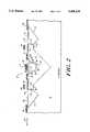
- FIG. 2is a cross-sectional view of the micromechanical vibrating string accelerometer of FIG. 1 taken along lines 2--2;
- FIG. 3is a block diagram illustrating the heater electronics employed in the present invention.
- FIGS. 4A-4Dillustrate the method of fabricating the tension relief and mass support beams of the present invention.
- FIGS. 5A-5Cillustrate an alternative method for fabricating tension relief and mass support beams of this invention.
- a monolithic, micromechanical vibrating string accelerometer with trimmable resonant frequency 10, FIG. 1 according to the present inventionis fabricated from a single silicon substrate 12 employing the technique of selective oxide removal, diffusions into the substrate through the removed oxide regions, and anisotropic etching. Such methods will be further described herein and are also fully disclosed in Applicant's co-pending U.S. patent application Ser. No. 143,515 entitled “Method and Apparatus for Semi-Conductor Chip Transducer" which is incorporated herein by reference.
- etch stop diffusions and subsequent selective anisotropic etchingcreate etched pit 14 having sloped sidewalls 16.
- micromechanical vibrating string accelerometer 18Suspended over etched pit 14 is micromechanical vibrating string accelerometer 18 comprising central proof mass 20 which is generally equally supported by flexible elements 22 and 24. Flexible elements 22 and 24 are isolated from proof mass 20 such as by dielectric lap joints 26.
- each of flexible elements 22 and 24is attached to opposite sides of proof mass 20 and generally colinear with acceleration sensitive axis 28.
- the second end of each of the flexible elementsis attached to tension relief beams 30 and 32.
- first and second tension recief beamsare shown in the preferred embodiment, only one tension relief beam is required to trim the resonant frequencies of both the first and second flexible elements.
- the initial tension on flexible elements 22 and 24is controlled by tension relief beams 30 and 32 which may be trimmed after the accelerometer has been fabricated to obtain a desired resonant frequency in flexible elements 22 and 24.
- Tension relief beams 30 and 32 formed by openings 36 and 38 and supports 40 and 42serve to relieve the stress by allowing the tension relief beams to deflect or bow slightly, thereby reducing the torsional stiffness of flexible elements 22 and 24 and serving to lower the resonant frequency of the flexible elements.
- Tension relief beams and a method for trimming the resonant frequency of a structure employing tension relief beamsare described in greater detail in Applicant's co-pending U.S. patent application Ser. No. 470,938 entitled "Micromechanical Device with a Trimmable Resonant Frequency Structure and Method of Trimming Same" incorporated herein by reference.
- Support structures 40 and 42further include removable regions 44 which have a thickness which is less than the thickness of the surrounding support structures 40 and 42. Providing areas of reduced thickness 44 facilitates enlargement of openings 36 and 38 as shown at 46, thereby further reducing the tension on tension relief beams 30 and 32 for trimming the resonant frequency of flexures 22 and 24 after the micromechanical vibrating string accelerometer has been fabricated. Trimming of the resonant frequency as shown at location 46 may be performed, for example, by utilizing a source of high intensity radiant energy such as a lasingtip to remove some of the area of reduced thickness 44. Support structures 40 and 42 are electrically isolated from silicon substrate 12 by means such as dielectric lap joints 48 and 50. Alternatively, support structures 40 and 42 may be isolated by means of a PN junction at regions 48 and 50.
- Proof mass 20is supported by proof mass support beams 52 and 54 which are mechanically connected to the proof mass and may be electrically isolated from the substrate.
- the mass support beams 52 and 54are thin silicon ribbons having a high height-to-width ratio of typically 10-to-1. For example, mass support beams measuring 1 micron wide ⁇ 10 microns high support the proof mass and prevent it from sagging while allowing the proof mass to move colinearly along the acceleration sensitive axis 28.
- flexible elements 22 and 24are driven in a self-resonant mode by drive electronics such as buried drive electrodes 56 and 58, and sensed by sense electrodes such as bridge sense electrodes 60 and 62.
- Electrical contact regions 74 and 76are provided to contact support structures 40 and 42 which are attached to flexible elements 22 and 24. These contacts regions contact the support structures through an opening in the dielectric lap joints as shown at 48 and 50.
- the footings of bridge electrodes 60 and 62may be surrounded by P-type junction isolation regions 64 which may be used in a "driven shield” mode to effectively electrically isolate the bridge electrodes from the surrounding substrate, minimizing parasitic capacitance and resulting in lower noise and increased accuracy.
- the monolithic micromechanical vibrating string accelerometer of the present inventionuses on chip drive electronics 68 and sense electronics 66 and 67 to provide the drive and sense signals to the bridge, buried, and resonant structure electrodes.
- the drive and sense electronicsinclude a number of buffers and amplifiers. Such electronics are described in greater detail in Applicant's co-pending U.S. patent application Ser. No. 07/528,051 entitled “Advanced Accelerometer” incorporated herein by reference.
- Additional on-chip circuitryincludes heater electronics 70 which typically comprises a resistive element disposed in at least a portion of the substrate 14.
- Temperature sensing electronics 72 including a diode as well as other components,are coupled to heater electronics 70. The heater and temperature sensor insure that the accelerometer temperature is maintained at +/-0.01° C. to achieve measurement accuracy on the order of 1 ppm bias stability.
- the monolithic micromechanical vibrating string accelerometeris shown in cross-section in FIG. 2 including etched pit 14 having sloped walls 16, over which is suspended vibrating string accelerometer 18.
- Proof mass 20includes a mass of silicon approximately 400 microns long ⁇ 400 microns wide ⁇ 50 microns deep, upon which is plated a gold counterweight 78 approximately 400 microns long ⁇ 400 microns wide ⁇ 17.7 microns high. This provides the accelerometer with a center of gravity at point 80 and a sensitivity of approximately 4000 Hz/g.
- Proof mass 20is generally equally supported by flexible elements 22 and 24.
- the flexible elementsare thin ribbons of silicon typically 0.5 microns thick ⁇ 20 microns wide ⁇ 200 microns long, with a resonant frequency of approximately 90 kHz.
- Proof mass 20is fabricated by anisotropically etching a region 82 through a surface oxide layer to form the center of what is to become the silicon "tub" portion of proof mass 20.
- the sidewalls and bottom of proof of mass 20are then diffused with Boron as shown at 86 to form an etch stop for the subsequent etching process.
- the silicon "tub”is then backfilled by growing silicon over the Boron diffusion and capping the region silicon with a shallow Boron diffusion 88.
- the remainder of the proof mass and the adjacent structural regions 40, 42 and 90, 92also receive a boron diffusion.
- the proof of mass 20Prior to undercutting by the etching process which will mechanically isolate the accelerometer, the proof of mass 20 is electrically isolated from the flexible elements 22 and 24 by depositing and patterning thick silicon nitride layers 26 which form a dielectric lap joint between the proof mass and the adjacent supporting structure 92. Similarly, dielectric electrically isolates lap joints 94 and 96 are formed and provided.
- Flexible elements 22 and 24are formed by a separate shallow boron diffusion, typically having a post etch thickness of 0.5 to 1.0 microns. Each of the flexible elements have a first end attached to opposite sides of proof mass 20, while a second end is attached to tension relief beams 30 and 32. In the absence of acceleration, flexible elements 22 and 24 will have a natural resonant frequency. Acceleration along acceleration sensitive axis 28 will result in a small movement of the proof mass which will increase the tension in one flexible element and reduce the tension in the other flexible element. This change in tension in the flexible elements will result in a differential frequency shift between the flexible elements which is proportional to tile acceleration causing the frequency shift.
- Tension relief beams 30 and 32are formed by openings 36 and 38 in support structures 40 and 42.
- Support structures 40 and 42are also fabricated by a boron diffusion process prior to etching and undercutting.
- Nitride lap joint regions 94 and 96electrically isolate the support structures and the flexible elements from silicon substrate 12.
- PN junctionsmay be used by extending regions 40,42 into substrate 12.
- Flexible elements 22 and 24are driven in a self-resonant mode and their resonant frequency sensed by means of at least one pair of buried electrodes 56 and 58 and bridge electrodes 60 and 62.
- Accelerometer and substrate heater and sensor/controller electronicsare represented in block diagram 160, FIG. 3, wherein a heater 162 connected to a power source 164 is operative for maintaining a constant temperature of the substrate under control of sensor/controller 166 and sensor feedback signal path 168.
- On-chip circuitrywhich senses, heats and controls temperature are commercially available and well known to those skilled in the art.
- a feature of the monolithic, micromechanical vibrating string accelerometer of the instant inventionis the ability to provide high aspect ratio tension relief beams and proof mass support beams.
- a method for fabricating such beamsincludes etching a slit or cut 100, FIG. 4A, through an oxidized layer 102 covering substrate 104.
- a Boron diffusion 106, FIG. 4Bis then applied through etched slit 100.
- Etched slit 100may be fabricated by means such as plasma etching or anisotropic etching.
- Slit 100is then backfilled with silicon 108, FIG. 4C, by epitaxially growing silicon in the slit, and capping the silicon with a shallow diffusion 110. After anisotropic etching and undercutting of the structure, a high aspect ratio beam 112 remains. This method may be utilized to fabricate both tension relief and mass support beams. Alternatively, the slit may be left unfilled and a high aspect ratio "U" shaped box like structure will remain after etching to provide the support structure.
- slit 100is Boron diffused 106 as previously illustrated in FIG. 4B.
- the structure of FIG. 5Bis again plasma etched to remove the bottom portion 114 of Boron diffusion 106, leaving side diffusions 116 and 118 intact.
- dual parallel support beams 120 and 122remain. This technique may yield two parallel beams with aspect ratios of 10 or more and widths as low as 0.1 microns.
Landscapes
- Physics & Mathematics (AREA)
- General Physics & Mathematics (AREA)
- Pressure Sensors (AREA)
Abstract
Description
This invention relates to accelerometers and more particularly, to a monolithic, micromachined, vibrating string accelerometer.
Accelerometers serve as one of the major sensors used in inertial navigation systems as well as various other safety and control systems.
Accurate and reliable accelerometers require great precision and uniform operating results. Prior art accelerometers are generally assembled from a number of components which creates tremendous assembly problems associated with such precision devices. In addition, these accelerometers are typically large and may not be radiation hard.
Although other prior art accelerometers are fabricated utilizing a micromechanical process, no provisions are made for electrically isolating the proof mass from the flexures which is required to accurately and independently drive and sense the resonant frequency of each of the flexures. Additionally, none of these prior art devices have provided reliable means for easily and accurately adjusting the natural resonant frequency of the flexure.
This invention features a monolithic, micromechanical, vibrating string accelerometer with a trimmable resonant frequency fabricated from a silicon substrate which has been selectively etched to provide a resonant structure suspended over an etched pit. The resonant structure comprises an acceleration sensitive mass and at least two flexible elements each having a natural resonant frequency. Each of the flexible elements is disposed generally colinear with at least one acceleration sensitive axis of the accelerometer. A first end of each of the flexible elements is attached to opposite sides of the mass while at least one of the second ends are attached to at least one tension relief beam for providing stress relief of tensile forces between the suspended elements and the body of the structure.
In the preferred embodiment, there are first and second tension relief beams located adjacent removable regions of the resonant structure, for facilitating removal of a portion of the removable regions and increasing the length and width of the opening forming the tension relief beam. Enlarging the opening forming the tension relief beams allows for trimming the resonant frequency of the flexible elements. The preferred embodiment further includes mass support beams having a high height-to-width ratio, for supporting the mass over the etched pit. The preferred embodiment further includes drive electronics for causing the flexible elements to resonate at a resonant frequency, and sense electronics to measure the frequency of the resonating flexible elements by sensing capacitance variations between a sense electrode and the resonating flexible element.
This invention also includes a method for fabricating a monolithic, micromechanical vibrating accelerometer with a trimmable resonant frequency including the steps of providing a single silicon substrate having an oxidized layer over the substrate and selectively removing regions of the oxidized layer. The silicon substrate is selectively doped through the regions of removed oxidized layer, to form etch resistant regions in the substrate. The substrate is then etched with an anisotropic etchant, forming a non-etched resonant structure which includes an acceleration sensitive mass, at least first and second flexible elements generally suspending the mass above an etched pit, at least a first tension relief beam attached to one of the first and second flexible elements, and first and second mass support beams.
These and other features and advantages of the present invention are described below in the following description and the accompanying drawings in which:
FIG. 1 is a top view of a schematic representation of the micromechanical vibrating string accelerometer including the tension relief and mass support beams according to the present invention;
FIG. 2 is a cross-sectional view of the micromechanical vibrating string accelerometer of FIG. 1 taken alonglines 2--2;
FIG. 3 is a block diagram illustrating the heater electronics employed in the present invention;
FIGS. 4A-4D illustrate the method of fabricating the tension relief and mass support beams of the present invention; and
FIGS. 5A-5C illustrate an alternative method for fabricating tension relief and mass support beams of this invention.
A monolithic, micromechanical vibrating string accelerometer with trimmableresonant frequency 10, FIG. 1 according to the present invention is fabricated from asingle silicon substrate 12 employing the technique of selective oxide removal, diffusions into the substrate through the removed oxide regions, and anisotropic etching. Such methods will be further described herein and are also fully disclosed in Applicant's co-pending U.S. patent application Ser. No. 143,515 entitled "Method and Apparatus for Semi-Conductor Chip Transducer" which is incorporated herein by reference.
The etch stop diffusions and subsequent selective anisotropic etching create etchedpit 14 having slopedsidewalls 16. Suspended over etchedpit 14 is micromechanical vibratingstring accelerometer 18 comprisingcentral proof mass 20 which is generally equally supported byflexible elements Flexible elements proof mass 20 such as bydielectric lap joints 26.
One end of each offlexible elements proof mass 20 and generally colinear with accelerationsensitive axis 28. In the preferred embodiment, the second end of each of the flexible elements is attached totension relief beams flexible elements tension relief beams flexible elements
The Boron diffusion used to define the vibrating string accelerometer and the subsequent etching of the surrounding silicon causes shrinking that creates a high tensile force in the flexures.Tension relief beams openings flexible elements
To operate the micromechanical vibrating string accelerometer of the present invention,flexible elements drive electrodes bridge sense electrodes Electrical contact regions support structures flexible elements bridge electrodes junction isolation regions 64 which may be used in a "driven shield" mode to effectively electrically isolate the bridge electrodes from the surrounding substrate, minimizing parasitic capacitance and resulting in lower noise and increased accuracy.
The monolithic micromechanical vibrating string accelerometer of the present invention uses onchip drive electronics 68 andsense electronics heater electronics 70 which typically comprises a resistive element disposed in at least a portion of thesubstrate 14. Temperature sensingelectronics 72 including a diode as well as other components, are coupled toheater electronics 70. The heater and temperature sensor insure that the accelerometer temperature is maintained at +/-0.01° C. to achieve measurement accuracy on the order of 1 ppm bias stability.
The monolithic micromechanical vibrating string accelerometer is shown in cross-section in FIG. 2 including etchedpit 14 having slopedwalls 16, over which is suspended vibratingstring accelerometer 18.Proof mass 20 includes a mass of silicon approximately 400 microns long×400 microns wide×50 microns deep, upon which is plated agold counterweight 78 approximately 400 microns long×400 microns wide×17.7 microns high. This provides the accelerometer with a center of gravity atpoint 80 and a sensitivity of approximately 4000 Hz/g.
A feature of the monolithic, micromechanical vibrating string accelerometer of the instant invention is the ability to provide high aspect ratio tension relief beams and proof mass support beams. As illustrated in the embodiment shown in FIGS. 4A-4D, a method for fabricating such beams includes etching a slit or cut 100, FIG. 4A, through an oxidized layer 102covering substrate 104. ABoron diffusion 106, FIG. 4B is then applied through etchedslit 100.Etched slit 100 may be fabricated by means such as plasma etching or anisotropic etching.
In an alternative embodiment, slit 100 is Boron diffused 106 as previously illustrated in FIG. 4B. In contrast to step 4C, however, the structure of FIG. 5B is again plasma etched to remove thebottom portion 114 ofBoron diffusion 106, leaving side diffusions 116 and 118 intact. After anisotropic etching and undercutting, dual parallel support beams 120 and 122 remain. This technique may yield two parallel beams with aspect ratios of 10 or more and widths as low as 0.1 microns.
Although specific features of the invention are shown in some drawings and not in others, this is for convenience only as each feature may be combined with any or all of the other features in accordance with the invention.
Modifications and substitutions of the present invention by one of ordinary skill in the art are considered to be within the scope of the present invention, which is not to be limited except by the claims which follow.
Claims (25)
1. A monolithic micromechanical vibrating accelerometer with a trimmable resonant frequency, for detecting acceleration along at least one acceleration sensitive axis comprising:
a silicon substrate in which has been selectively etched a pit over which is suspended a non-etched silicon resonant structure comprising an acceleration sensitive mass and at least two flexible elements having a resonant frequency, said at least two flexible elements generally equally suspending said mass above said etched pit;
each of said flexible elements disposed generally colinear with said at least one acceleration sensitive axis, and having first and second ends, the first flexible element having its first end attached to a first side of said mass and the second flexible element having its first end attached to a second side of said mass diametrically opposed from said first side; and
said non-etched silicon resonant structure further comprising means for establishing a trimmable resonant frequency for said flexible elements, including at least a first opening having a predetermined length and width located proximate the second end of at least one of said first and second flexible elements, said at least a first opening including one edge located a predetermined distance from said second end of said at least one of said first and second flexible elements, said predetermined distance from said second end of said at least one of said first and second flexible elements to said one edge of said first opening defining a first tension relief beam, said first tension relief beam attached to the second end of said at least one of said first and second flexible elements, said first tension relief beam flexible in a direction parallel to said acceleration sensitive axis, for deflecting a first distance under longitudinal tension from said at least one of said first and second flexible elements and for providing stress relief of longitudinal tensile forces between said flexible elements and said tension relief beam, thereby establishing a trimmable resonant frequency for said flexible elements.
2. The accelerometer of claim 1 wherein said non-etched silicon resonant structure further includes a second opening having a predetermined length and width, located proximate the second end of the other of said first and second flexible elements, one edge of said second opening located a predetermined distance from the second end of the other of said first and second flexible elements, said predetermined distance from said second end of said other of said flexible elements to said one edge of said second opening defining a second tension relief beam deflecting a first distance under longitudinal tension from said other of said first and second flexible element, and to which is attached the second end of said other of said first and second flexible element.
3. The accelerometer of claim 2 in which said means for establishing a trimmable resonant frequency includes first and second regions of removable non-etched silicon resonant structure adjacent said first and second openings, for facilitating removal of a portion of said first and second regions for increasing at least one of the length and width of said first and second openings.
4. The accelerometer of claim 3 wherein said first and second regions of removable non-etched silicon resonant structure have a thickness which is less than the thickness of the surrounding non-etched silicon resonant structure, for permitting removal of at least a portion of said first and second regions of removable non-etched silicon resonant structure by a trimming instrument, for enlarging said first and second openings and for increasing said first distance of deflection of said first and second tension relief beams thereby trimming the frequency of said flexible elements.
5. The accelerometer of claim 4 wherein said trimming instrument includes a laser.
6. The accelerometer of claim 2 wherein said tension relief beams have a high height-to-width ratio.
7. The accelerometer of claim 6 wherein said height-to-width ratio is at least 2-to-1.
8. The accelerometer of claim 1 further including drive means, operative for causing said flexible elements to resonate at a resonant frequency.
9. The accelerometer of claim 8 wherein said drive means include buried electrodes and bridge electrodes.
10. The accelerometer of claim 9 wherein said bridge electrodes are electrically isolated from said silicon substrate.
11. The accelerometer of claim 1 further including sense means for measuring the resonant frequency of said flexible elements.
12. The accelerometer of claim 11 wherein said sense means includes a buffer/amplifier.
13. The accelerometer of claim 1 wherein said mass includes a silicon mass on which is disposed a counter weight.
14. The accelerometer of claim 13 in which said counter weight includes gold.
15. The accelerometer of claim 1 further including means for supporting said mass.
16. The accelerometer of claim 15 wherein said means for supporting the mass includes first and second silicon beams disposed generally perpendicular to said acceleration sensitive axis, and having first and second ends, the first support beam having its first end attached to one side of said mass and its second end attached to said substrate, the second support having its first end attached to an opposite side of said mass and its second end attached to said substrate, for allowing said mass to move along said acceleration sensitive axis and generally preventing movement of said mass transverse to the direction of said acceleration sensitive axis.
17. The accelerometer of claim 16 wherein said support beams have a high height-to-width ratio.
18. The accelerometer of claim 17 wherein said high height-to-width ratio is at least 2-to-1.
19. The accelerometer of claim 1 further including heater means for keeping said substrate and said resonant structure at a generally constant temperature.
20. The accelerometer of claim 19 further including temperature sensing means, for monitoring the temperature of said substrate and said resonant structure, and operative for selectively enabling and disabling said heater means at preselected temperatures.
21. The accelerometer of claim 1 further including electrical isolation means, for electrically isolating said mass from said flexible elements.
22. The accelerometer of claim 21 wherein said electrical isolation means includes a dielectric lap joint.
23. The accelerometer of claim 1 further including third and fourth flexible elements each having a first end attached on opposite sides of said mass, and disposed generally colinear with a second acceleration sensitive axis which is generally perpendicular to the first acceleration sensitive axis.
24. A monolithic micromechanical vibrating accelerometer, for detecting acceleration along at least one acceleration sensitive axis comprising:
a silicon substrate in which has been selectively etched a pit over which is suspended a non-etched silicon resonant structure comprising an acceleration sensitive mass and at least two flexible elements having a resonant frequency, said at least two flexible elements generally equally suspending said mass above said etched pit;
each of said flexible elements disposed generally colinear with said at least one acceleration sensitive axis, and having first and second ends, the first flexible element having its first end attached to a first side of said mass, and the second flexible element having its first end attached to a second side of said mass diametrically opposed from said first side;
means for electrically isolating said mass from said flexible elements;
said non-etched silicon resonant structure further comprising means for establishing a trimmable resonant frequency for each of said flexible elements, including first and second openings having a predetermined length and width located proximate the second end of said first and second flexible elements respectively, each of said first and second openings including one edge located a predetermined distance from said second end of said first and second flexible elements, said predetermined distance from said second end of said first and second flexible elements to said one edge of said first and second openings defining first and second tension relief beams, said first tension relief beam attached to the second end of said first flexible element and said second tension relief beam attached to the second end of said second flexible element, said first and second tension relief beams flexible in a direction parallel to said acceleration sensitive axis, for deflecting a first distance under longitudinal tension from said first and second flexible elements, and for providing stress relief of longitudinal tensile forces between said flexible elements and said tension relief beam, thereby establishing a trimmable resonant frequency for said flexible elements; and
said means for establishing a trimmable resonant frequency for said flexible elements including first and second regions of removable non-etched silicon resonant structure adjacent said first and second openings, said first and second regions of removable non-etched silicon resonant structure having a thickness which is less than the thickness of the surrounding non-etched silicon resonant structure, for permitting removal of at least a portion of said first and second removable regions by a trimming instrument, for increasing the length and width of said first and second openings and for increasing said first distance of deflection of said first and second tension relief beams thereby trimming the frequency of said flexible elements.
25. A monolithic micromechanical vibrating accelerometer, for detecting acceleration along at least one acceleration sensitive axis comprising:
a silicon substrate in which has been selectively etched a pit, over which is suspended a non-etched silicon resonant structure comprising an acceleration sensitive mass and at least two flexible elements having a resonant frequency, said at least two flexible elements generally equally suspending said mass above said etched pit;
each of said flexible elements disposed generally colinear with said at least one acceleration sensitive axis, and having first and second ends, the first flexible element having its first end attached to a first side of said mass, and the second flexible element having its first end attached to a second side of said mass diametrically opposed from said first side;
means for electrically isolating said mass from said flexible elements;
means for supporting the mass including first and second silicon beams disposed generally perpendicular to said acceleration sensitive axis, and having first and second ends, the first support beam having its first end attached to one side of said mass and its second end attached to a first region of said substrate, the second support beam having its first end attached to an opposite side of said mass and its second end attached to a second region of said substrate diametrically opposed from said first region, for allowing said mass to move in a direction parallel to said acceleration sensitive axis and generally preventing movement of said mass transverse to the direction of said acceleration sensitive axis;
said non-etched silicon resonant structure further comprising means for establishing a trimmable resonant frequency for each of said flexible elements, including first and second openings having a predetermined length and width located proximate the second end of said first and second flexible elements respectively, each of said first and second openings including one edge located a predetermined distance from said second end of said first and second flexible elements, said predetermined distance from said second end of said first and second flexible elements to said one edge of said first and second openings defining first and second tension relief beams, said first tension relief beam attached to the second end of said first flexible element and said second tension relief beam attached to the second end of said second flexible element, said first and second tension relief beams flexible in a direction parallel to said acceleration sensitive axis, for deflecting a first distance under longitudinal tension from said first and second flexible elements and for providing stress relief of longitudinal tensile forces between said flexible elements and said tension relief beams, thereby establishing a trimmable resonant frequency for said flexible elements; and
said means for establishing a trimmable resonant frequency for said flexible elements including first and second regions of removable non-etched silicon resonant structure adjacent said first and second openings, said first and second regions of removable non-etched silicon resonant structure having a thickness which is less than the thickness of the surrounding non-etched silicon resonant structure, for permitting removal of at least a portion of said first and second removable regions by a trimming instrument, for increasing the length and width of said first and second openings and for increasing said first distance of deflection of said first and second tension relief beams thereby trimming the frequency of said flexible elements.
Priority Applications (5)
| Application Number | Priority Date | Filing Date | Title |
|---|---|---|---|
| US07/599,131US5408119A (en) | 1990-10-17 | 1990-10-17 | Monolithic micromechanical vibrating string accelerometer with trimmable resonant frequency |
| US08/242,274US5605598A (en) | 1990-10-17 | 1994-05-13 | Monolithic micromechanical vibrating beam accelerometer with trimmable resonant frequency |
| US08/422,432US5507911A (en) | 1990-10-17 | 1995-04-14 | Monolithic micromechanical vibrating string accelerometer with trimmable resonant frequency |
| US08/602,512US5760305A (en) | 1990-10-17 | 1996-02-20 | Monolithic micromechanical vibrating beam accelerometer with trimmable resonant frequency |
| US09/010,458US5969250A (en) | 1990-10-17 | 1998-01-21 | Micromechanical accelerometer having a peripherally suspended proof mass |
Applications Claiming Priority (1)
| Application Number | Priority Date | Filing Date | Title |
|---|---|---|---|
| US07/599,131US5408119A (en) | 1990-10-17 | 1990-10-17 | Monolithic micromechanical vibrating string accelerometer with trimmable resonant frequency |
Related Child Applications (2)
| Application Number | Title | Priority Date | Filing Date |
|---|---|---|---|
| US08/242,274Continuation-In-PartUS5605598A (en) | 1990-10-17 | 1994-05-13 | Monolithic micromechanical vibrating beam accelerometer with trimmable resonant frequency |
| US08/422,432DivisionUS5507911A (en) | 1990-10-17 | 1995-04-14 | Monolithic micromechanical vibrating string accelerometer with trimmable resonant frequency |
Publications (1)
| Publication Number | Publication Date |
|---|---|
| US5408119Atrue US5408119A (en) | 1995-04-18 |
Family
ID=24398349
Family Applications (2)
| Application Number | Title | Priority Date | Filing Date |
|---|---|---|---|
| US07/599,131Expired - LifetimeUS5408119A (en) | 1990-10-17 | 1990-10-17 | Monolithic micromechanical vibrating string accelerometer with trimmable resonant frequency |
| US08/422,432Expired - LifetimeUS5507911A (en) | 1990-10-17 | 1995-04-14 | Monolithic micromechanical vibrating string accelerometer with trimmable resonant frequency |
Family Applications After (1)
| Application Number | Title | Priority Date | Filing Date |
|---|---|---|---|
| US08/422,432Expired - LifetimeUS5507911A (en) | 1990-10-17 | 1995-04-14 | Monolithic micromechanical vibrating string accelerometer with trimmable resonant frequency |
Country Status (1)
| Country | Link |
|---|---|
| US (2) | US5408119A (en) |
Cited By (5)
| Publication number | Priority date | Publication date | Assignee | Title |
|---|---|---|---|---|
| WO1998014786A1 (en)* | 1996-10-03 | 1998-04-09 | Commissariat A L'energie Atomique | Sensor, in particular accelerometer, and actuator, and method for making a sensor or actuator structure with electric insulation localised in a substrate plate |
| US5969249A (en)* | 1997-05-07 | 1999-10-19 | The Regents Of The University Of California | Resonant accelerometer with flexural lever leverage system |
| WO2002103365A2 (en) | 2001-06-19 | 2002-12-27 | Microsensors, Inc. | Mems sensor with single central anchor and motion-limiting connection geometry |
| US20040152979A1 (en)* | 2003-02-04 | 2004-08-05 | Nemoto Kyorindo Co., Ltd. | Liquid injection system for detecting when piston pusher of liquid injector grips piston flange of liquid syringe |
| DE19620832B4 (en)* | 1995-05-25 | 2005-09-29 | Samsung Electronics Co., Ltd., Suwon | Method for adjusting the natural frequency of a dual-axis vibration design |
Families Citing this family (21)
| Publication number | Priority date | Publication date | Assignee | Title |
|---|---|---|---|---|
| US5473945A (en) | 1990-02-14 | 1995-12-12 | The Charles Stark Draper Laboratory, Inc. | Micromechanical angular accelerometer with auxiliary linear accelerometer |
| US5914801A (en)* | 1996-09-27 | 1999-06-22 | Mcnc | Microelectromechanical devices including rotating plates and related methods |
| US6318176B1 (en) | 1999-03-26 | 2001-11-20 | Seagate Technology Llc | Rotational inductive accelerometer |
| US6275320B1 (en) | 1999-09-27 | 2001-08-14 | Jds Uniphase, Inc. | MEMS variable optical attenuator |
| US6373682B1 (en) | 1999-12-15 | 2002-04-16 | Mcnc | Electrostatically controlled variable capacitor |
| US6485273B1 (en) | 2000-09-01 | 2002-11-26 | Mcnc | Distributed MEMS electrostatic pumping devices |
| US6590267B1 (en) | 2000-09-14 | 2003-07-08 | Mcnc | Microelectromechanical flexible membrane electrostatic valve device and related fabrication methods |
| US6377438B1 (en) | 2000-10-23 | 2002-04-23 | Mcnc | Hybrid microelectromechanical system tunable capacitor and associated fabrication methods |
| US6396620B1 (en) | 2000-10-30 | 2002-05-28 | Mcnc | Electrostatically actuated electromagnetic radiation shutter |
| US6907150B2 (en) | 2001-02-07 | 2005-06-14 | Shipley Company, L.L.C. | Etching process for micromachining crystalline materials and devices fabricated thereby |
| US6885786B2 (en) | 2001-02-07 | 2005-04-26 | Shipley Company, L.L.C. | Combined wet and dry etching process for micromachining of crystalline materials |
| US20030021572A1 (en)* | 2001-02-07 | 2003-01-30 | Steinberg Dan A. | V-groove with tapered depth and method for making |
| US6964804B2 (en)* | 2001-02-14 | 2005-11-15 | Shipley Company, L.L.C. | Micromachined structures made by combined wet and dry etching |
| US20020195417A1 (en)* | 2001-04-20 | 2002-12-26 | Steinberg Dan A. | Wet and dry etching process on <110> silicon and resulting structures |
| US20040127855A1 (en)* | 2002-10-10 | 2004-07-01 | Nmt Medical, Inc. | Hemostasis valve |
| US6978673B2 (en)* | 2003-02-07 | 2005-12-27 | Honeywell International, Inc. | Methods and systems for simultaneously fabricating multi-frequency MEMS devices |
| EP1479648A3 (en) | 2003-05-23 | 2005-10-19 | Rohm and Haas Electronic Materials, L.L.C. | Etching process for micromachining crystalline materials and devices fabricated thereby |
| WO2006012510A1 (en)* | 2004-07-23 | 2006-02-02 | Afa Controls, Llc | Microvalve assemblies and related methods |
| US20070163346A1 (en)* | 2006-01-18 | 2007-07-19 | Honeywell International Inc. | Frequency shifting of rotational harmonics in mems devices |
| WO2008061319A1 (en)* | 2006-11-24 | 2008-05-29 | Mems-Id Pty Ltd | Micromechanical resonant arrays and methods of making |
| US8187902B2 (en)* | 2008-07-09 | 2012-05-29 | The Charles Stark Draper Laboratory, Inc. | High performance sensors and methods for forming the same |
Citations (67)
| Publication number | Priority date | Publication date | Assignee | Title |
|---|---|---|---|---|
| US3696429A (en)* | 1971-05-24 | 1972-10-03 | Cutler Hammer Inc | Signal cancellation system |
| US4044305A (en)* | 1975-03-17 | 1977-08-23 | The Charles Stark Draper Laboratory, Inc. | Apparatus for providing a displacement representative of the magnitude of a signal |
| US4122448A (en)* | 1977-07-21 | 1978-10-24 | Westinghouse Electric Corp. | Automatic phase and gain balance controller for a baseband processor |
| US4144764A (en)* | 1978-05-11 | 1979-03-20 | Schaevitz Engineering | Servo amplifier for an electrically damped accelerometer |
| US4155257A (en)* | 1977-05-23 | 1979-05-22 | The Singer Company | Temperature compensated vibrating beam accelerometer |
| JPS55121728A (en)* | 1979-03-12 | 1980-09-19 | Seiko Instr & Electronics Ltd | Crystal oscillator |
| US4234666A (en)* | 1978-07-26 | 1980-11-18 | Western Electric Company, Inc. | Carrier tapes for semiconductor devices |
| US4321500A (en)* | 1979-12-17 | 1982-03-23 | Paroscientific, Inc. | Longitudinal isolation system for flexurally vibrating force transducers |
| US4336718A (en)* | 1980-09-08 | 1982-06-29 | Lear Siegler, Inc. | Control circuit for accelerometer |
| US4342227A (en)* | 1980-12-24 | 1982-08-03 | International Business Machines Corporation | Planar semiconductor three direction acceleration detecting device and method of fabrication |
| US4381672A (en)* | 1981-03-04 | 1983-05-03 | The Bendix Corporation | Vibrating beam rotation sensor |
| JPS58136125A (en)* | 1982-02-05 | 1983-08-13 | Seiko Instr & Electronics Ltd | Coupled crystal oscillator |
| US4414852A (en)* | 1981-09-14 | 1983-11-15 | Gould Inc. | Automatic zero balance circuit |
| JPS5937722A (en)* | 1982-08-26 | 1984-03-01 | Matsushima Kogyo Co Ltd | Longitudinal oscillation type piezoelectric oscillator |
| US4447753A (en)* | 1981-03-25 | 1984-05-08 | Seiko Instruments & Electronics Ltd. | Miniature GT-cut quartz resonator |
| JPS59158566A (en)* | 1983-02-28 | 1984-09-08 | Nippon Denso Co Ltd | Semiconductor acceleration sensor |
| US4478077A (en)* | 1982-09-30 | 1984-10-23 | Honeywell Inc. | Flow sensor |
| US4478076A (en)* | 1982-09-30 | 1984-10-23 | Honeywell Inc. | Flow sensor |
| US4483194A (en)* | 1981-07-02 | 1984-11-20 | Centre Electronique Horloger S.A. | Accelerometer |
| US4484382A (en)* | 1981-05-15 | 1984-11-27 | Seiko Instruments & Electronics Ltd. | Method of adjusting resonant frequency of a coupling resonator |
| US4499778A (en)* | 1981-02-03 | 1985-02-19 | Northrop Corporation | Flexure mount assembly for a dynamically tuned gyroscope and method of manufacturing same |
| US4522072A (en)* | 1983-04-22 | 1985-06-11 | Insouth Microsystems, Inc. | Electromechanical transducer strain sensor arrangement and construction |
| US4524619A (en)* | 1984-01-23 | 1985-06-25 | Piezoelectric Technology Investors, Limited | Vibratory angular rate sensor system |
| US4538461A (en)* | 1984-01-23 | 1985-09-03 | Piezoelectric Technology Investors, Inc. | Vibratory angular rate sensing system |
| US4590801A (en)* | 1983-09-02 | 1986-05-27 | Sundstrand Data Control, Inc. | Apparatus for measuring inertial specific force and angular rate of a moving body |
| US4598585A (en)* | 1984-03-19 | 1986-07-08 | The Charles Stark Draper Laboratory, Inc. | Planar inertial sensor |
| US4600934A (en)* | 1984-01-06 | 1986-07-15 | Harry E. Aine | Method of undercut anisotropic etching of semiconductor material |
| US4629957A (en)* | 1984-03-27 | 1986-12-16 | Emi Limited | Sensing apparatus |
| US4651564A (en)* | 1982-09-30 | 1987-03-24 | Honeywell Inc. | Semiconductor device |
| US4653326A (en)* | 1984-01-12 | 1987-03-31 | Commissariat A L'energie Atomique | Directional accelerometer and its microlithographic fabrication process |
| US4654663A (en)* | 1981-11-16 | 1987-03-31 | Piezoelectric Technology Investors, Ltd. | Angular rate sensor system |
| GB2183040A (en)* | 1985-11-19 | 1987-05-28 | Stc Plc | Transducer |
| US4670092A (en)* | 1986-04-18 | 1987-06-02 | Rockwell International Corporation | Method of fabricating a cantilever beam for a monolithic accelerometer |
| US4674331A (en)* | 1984-07-27 | 1987-06-23 | Watson Industries Inc. | Angular rate sensor |
| JPS62221164A (en)* | 1986-03-24 | 1987-09-29 | Mitsubishi Electric Corp | semiconductor acceleration sensor |
| US4699006A (en)* | 1984-03-19 | 1987-10-13 | The Charles Stark Draper Laboratory, Inc. | Vibratory digital integrating accelerometer |
| US4706374A (en)* | 1984-10-19 | 1987-11-17 | Nissan Motor Co., Ltd. | Method of manufacture for semiconductor accelerometer |
| US4727752A (en)* | 1987-02-04 | 1988-03-01 | Sundstrand Data Control, Inc. | Pseudosinusoidal oscillator drive system |
| US4735506A (en)* | 1985-04-01 | 1988-04-05 | Litton Systems, Inc. | Phase nulling optical gyroscope |
| US4736629A (en)* | 1985-12-20 | 1988-04-12 | Silicon Designs, Inc. | Micro-miniature accelerometer |
| JPS63169078A (en)* | 1987-01-06 | 1988-07-13 | Nippon Denso Co Ltd | Semiconductor vibration and acceleration sensor |
| US4761743A (en)* | 1985-12-02 | 1988-08-02 | The Singer Company | Dynamic system analysis in a vibrating beam accelerometer |
| US4764244A (en)* | 1985-06-11 | 1988-08-16 | The Foxboro Company | Resonant sensor and method of making same |
| US4783237A (en)* | 1983-12-01 | 1988-11-08 | Harry E. Aine | Solid state transducer and method of making same |
| US4805456A (en)* | 1987-05-19 | 1989-02-21 | Massachusetts Institute Of Technology | Resonant accelerometer |
| US4834538A (en)* | 1987-03-19 | 1989-05-30 | Stc Plc | Fibre optic gyroscope with nulling feedback control loop |
| USRE32931E (en)* | 1984-01-23 | 1989-05-30 | Piezoelectric Technology Investors, Inc. | Vibratory angular rate sensor system |
| US4869107A (en)* | 1986-08-06 | 1989-09-26 | Nissan Motor Co., Ltd. | Acceleration sensor for use in automotive vehicle |
| US4882933A (en)* | 1988-06-03 | 1989-11-28 | Novasensor | Accelerometer with integral bidirectional shock protection and controllable viscous damping |
| US4893509A (en)* | 1988-12-27 | 1990-01-16 | General Motors Corporation | Method and product for fabricating a resonant-bridge microaccelerometer |
| US4898032A (en)* | 1987-07-08 | 1990-02-06 | Thorn Emi Electronics Limited | Rate sensor |
| US4900971A (en)* | 1988-03-10 | 1990-02-13 | Seiko Electronic Components Ltd. | Face shear mode quartz crystal resonator |
| US4916520A (en)* | 1987-09-24 | 1990-04-10 | Nec Corporation | Semiconductor device with airbridge interconnection |
| US4922756A (en)* | 1988-06-20 | 1990-05-08 | Triton Technologies, Inc. | Micro-machined accelerometer |
| US4929860A (en)* | 1988-05-17 | 1990-05-29 | Sundstrand Data Control, Inc. | Electrode configuration for vibrating beam transducers |
| USRE33479E (en)* | 1984-01-23 | 1990-12-11 | Piezoelectric Technology Investors | Vibratory angular rate sensing system |
| US4981359A (en)* | 1989-06-19 | 1991-01-01 | Litton Systems, Inc. | Ring laser gyroscope dither drive system and method |
| US5001383A (en)* | 1988-09-09 | 1991-03-19 | Seiko Electronic Components Ltd. | Longitudinal quartz crystal resonator |
| US5016072A (en)* | 1988-01-13 | 1991-05-14 | The Charles Stark Draper Laboratory, Inc. | Semiconductor chip gyroscopic transducer |
| US5038613A (en)* | 1989-05-19 | 1991-08-13 | Matsushita Electric Industrial Co., Ltd. | Angular rate detecting device |
| US5090809A (en)* | 1990-06-04 | 1992-02-25 | Ferrar Carl M | Modulation frequency control in a fiber optic rotation sensor |
| US5094537A (en)* | 1991-03-08 | 1992-03-10 | Honeywell Inc. | Signal processing system for correcting ring laser gyroscope readout |
| US5138883A (en)* | 1989-09-29 | 1992-08-18 | Minister Of National Defence Of Her Majesty's Canadian Government | Analog torque rebalance loop for a tuned rotor gyroscope |
| US5205171A (en)* | 1991-01-11 | 1993-04-27 | Northrop Corporation | Miniature silicon accelerometer and method |
| US5226321A (en)* | 1990-05-18 | 1993-07-13 | British Aerospace Public Limited Company | Vibrating planar gyro |
| US5233874A (en)* | 1991-08-19 | 1993-08-10 | General Motors Corporation | Active microaccelerometer |
| US5241861A (en)* | 1991-02-08 | 1993-09-07 | Sundstrand Corporation | Micromachined rate and acceleration sensor |
Family Cites Families (46)
| Publication number | Priority date | Publication date | Assignee | Title |
|---|---|---|---|---|
| US33479A (en)* | 1861-10-15 | Improved blacksmith s portable forge | ||
| US32931A (en)* | 1861-07-30 | Machine for tupvning tapering forms | ||
| CH359552A (en)* | 1957-07-20 | 1962-01-15 | Boelkow Entwicklungen Kg | Measuring and control device for very low speeds |
| GB989101A (en)* | 1961-07-11 | 1965-04-14 | Mini Of Aviat London | Improvements in gyroscope apparatus |
| US3370458A (en)* | 1965-09-10 | 1968-02-27 | W C Dillon & Company Inc | Mechanical force gauge |
| US3913035A (en)* | 1974-07-01 | 1975-10-14 | Motorola Inc | Negative resistance high-q-microwave oscillator |
| JPS6025926B2 (en)* | 1976-10-01 | 1985-06-21 | シャープ株式会社 | Crystal oscillator |
| DE3112560C2 (en)* | 1981-03-30 | 1983-01-27 | M.A.N.- Roland Druckmaschinen AG, 6050 Offenbach | Proximity switch which, by means of excitation and detection of a field, indicates the presence or absence of field-changing objects in a defined distance range from the proximity switch using a binary signal |
| US4406992A (en)* | 1981-04-20 | 1983-09-27 | Kulite Semiconductor Products, Inc. | Semiconductor pressure transducer or other product employing layers of single crystal silicon |
| US4495499A (en)* | 1981-09-08 | 1985-01-22 | David Richardson | Integrated oscillator-duplexer-mixer |
| US4411741A (en)* | 1982-01-12 | 1983-10-25 | University Of Utah | Apparatus and method for measuring the concentration of components in fluids |
| DE3213720C2 (en)* | 1982-04-14 | 1985-09-05 | Bodenseewerk Gerätetechnik GmbH, 7770 Überlingen | Dynamically coordinated cardan suspension with two degrees of freedom |
| US4621925A (en)* | 1982-11-11 | 1986-11-11 | Fujitsu Limited | Fiber-optic gyro |
| US4596158A (en)* | 1983-01-05 | 1986-06-24 | Litton Systems, Inc. | Tuned gyroscope with dynamic absorber |
| US4490772A (en)* | 1983-06-13 | 1984-12-25 | Blickstein Martin J | Voltage and mechanically variable trimmer capacitor |
| US4619001A (en)* | 1983-08-02 | 1986-10-21 | Matsushita Electric Industrial Co., Ltd. | Tuning systems on dielectric substrates |
| US4585083A (en)* | 1983-11-01 | 1986-04-29 | Shinko Denshi Company Ltd. | Mechanism for detecting load |
| US4628283A (en)* | 1983-11-07 | 1986-12-09 | The Narda Microwave Corporation | Hermetically sealed oscillator with dielectric resonator tuned through dielectric window by adjusting screw |
| US4899587A (en)* | 1984-01-23 | 1990-02-13 | Piezoelectric Technology Investors, Limited | Method for sensing rotation using vibrating piezoelectric elements |
| CA1234705A (en)* | 1984-03-22 | 1988-04-05 | Suzushi Kimura | Angular velocity sensor |
| US4674180A (en)* | 1984-05-01 | 1987-06-23 | The Foxboro Company | Method of making a micromechanical electric shunt |
| US4680606A (en)* | 1984-06-04 | 1987-07-14 | Tactile Perceptions, Inc. | Semiconductor transducer |
| US4644793A (en)* | 1984-09-07 | 1987-02-24 | The Marconi Company Limited | Vibrational gyroscope |
| US4674319A (en)* | 1985-03-20 | 1987-06-23 | The Regents Of The University Of California | Integrated circuit sensor |
| US4705659A (en)* | 1985-04-01 | 1987-11-10 | Motorola, Inc. | Carbon film oxidation for free-standing film formation |
| US4639690A (en)* | 1985-07-05 | 1987-01-27 | Litton Systems, Inc. | Tunable, dielectric-resonator-stabilized oscillator and method of tuning same |
| US4679434A (en)* | 1985-07-25 | 1987-07-14 | Litton Systems, Inc. | Integrated force balanced accelerometer |
| US4744248A (en)* | 1985-07-25 | 1988-05-17 | Litton Systems, Inc. | Vibrating accelerometer-multisensor |
| US4744249A (en)* | 1985-07-25 | 1988-05-17 | Litton Systems, Inc. | Vibrating accelerometer-multisensor |
| JPS6293668A (en)* | 1985-10-21 | 1987-04-30 | Hitachi Ltd | Angular velocity/acceleration detector |
| JPS6295421A (en)* | 1985-10-22 | 1987-05-01 | Tokyo Keiki Co Ltd | Gyroscope |
| US4747312A (en)* | 1986-02-21 | 1988-05-31 | Fischer & Porter Co. | Double-loop Coriolis type mass flowmeter |
| US4712439A (en)* | 1986-02-24 | 1987-12-15 | Henry North | Apparatus for producing a force |
| FR2604791B1 (en)* | 1986-10-02 | 1988-11-25 | Commissariat Energie Atomique | METHODS OF MANUFACTURING A PIEZORESISTIVE GAUGE AND AN ACCELEROMETER COMPRISING SUCH A GAUGE |
| US4743789A (en)* | 1987-01-12 | 1988-05-10 | Puskas William L | Variable frequency drive circuit |
| US4884446A (en)* | 1987-03-12 | 1989-12-05 | Ljung Per B | Solid state vibrating gyro |
| US4851080A (en)* | 1987-06-29 | 1989-07-25 | Massachusetts Institute Of Technology | Resonant accelerometer |
| US4789803A (en)* | 1987-08-04 | 1988-12-06 | Sarcos, Inc. | Micropositioner systems and methods |
| US4808948A (en)* | 1987-09-28 | 1989-02-28 | Kulicke And Soffa Indusries, Inc. | Automatic tuning system for ultrasonic generators |
| US4895616A (en)* | 1987-12-07 | 1990-01-23 | Honeywell Inc. | Method for making thin film orthogonal microsensor for air flow |
| US4890812A (en)* | 1988-02-01 | 1990-01-02 | Litton Systems, Inc. | Temperature compensated mount for supporting a ring laser gyro |
| US4808549A (en)* | 1988-05-27 | 1989-02-28 | Ford Motor Company | Method for fabricating a silicon force transducer |
| US4855544A (en)* | 1988-09-01 | 1989-08-08 | Honeywell Inc. | Multiple level miniature electromechanical accelerometer switch |
| US4901586A (en)* | 1989-02-27 | 1990-02-20 | Sundstrand Data Control, Inc. | Electrostatically driven dual vibrating beam force transducer |
| US5045152A (en)* | 1989-03-06 | 1991-09-03 | Ford Motor Company | Force transducer etched from silicon |
| US4981552A (en)* | 1989-04-06 | 1991-01-01 | Ford Motor Company | Method for fabricating a silicon accelerometer responsive to three orthogonal force components |
- 1990
- 1990-10-17USUS07/599,131patent/US5408119A/ennot_activeExpired - Lifetime
- 1995
- 1995-04-14USUS08/422,432patent/US5507911A/ennot_activeExpired - Lifetime
Patent Citations (67)
| Publication number | Priority date | Publication date | Assignee | Title |
|---|---|---|---|---|
| US3696429A (en)* | 1971-05-24 | 1972-10-03 | Cutler Hammer Inc | Signal cancellation system |
| US4044305A (en)* | 1975-03-17 | 1977-08-23 | The Charles Stark Draper Laboratory, Inc. | Apparatus for providing a displacement representative of the magnitude of a signal |
| US4155257A (en)* | 1977-05-23 | 1979-05-22 | The Singer Company | Temperature compensated vibrating beam accelerometer |
| US4122448A (en)* | 1977-07-21 | 1978-10-24 | Westinghouse Electric Corp. | Automatic phase and gain balance controller for a baseband processor |
| US4144764A (en)* | 1978-05-11 | 1979-03-20 | Schaevitz Engineering | Servo amplifier for an electrically damped accelerometer |
| US4234666A (en)* | 1978-07-26 | 1980-11-18 | Western Electric Company, Inc. | Carrier tapes for semiconductor devices |
| JPS55121728A (en)* | 1979-03-12 | 1980-09-19 | Seiko Instr & Electronics Ltd | Crystal oscillator |
| US4321500A (en)* | 1979-12-17 | 1982-03-23 | Paroscientific, Inc. | Longitudinal isolation system for flexurally vibrating force transducers |
| US4336718A (en)* | 1980-09-08 | 1982-06-29 | Lear Siegler, Inc. | Control circuit for accelerometer |
| US4342227A (en)* | 1980-12-24 | 1982-08-03 | International Business Machines Corporation | Planar semiconductor three direction acceleration detecting device and method of fabrication |
| US4499778A (en)* | 1981-02-03 | 1985-02-19 | Northrop Corporation | Flexure mount assembly for a dynamically tuned gyroscope and method of manufacturing same |
| US4381672A (en)* | 1981-03-04 | 1983-05-03 | The Bendix Corporation | Vibrating beam rotation sensor |
| US4447753A (en)* | 1981-03-25 | 1984-05-08 | Seiko Instruments & Electronics Ltd. | Miniature GT-cut quartz resonator |
| US4484382A (en)* | 1981-05-15 | 1984-11-27 | Seiko Instruments & Electronics Ltd. | Method of adjusting resonant frequency of a coupling resonator |
| US4483194A (en)* | 1981-07-02 | 1984-11-20 | Centre Electronique Horloger S.A. | Accelerometer |
| US4414852A (en)* | 1981-09-14 | 1983-11-15 | Gould Inc. | Automatic zero balance circuit |
| US4654663A (en)* | 1981-11-16 | 1987-03-31 | Piezoelectric Technology Investors, Ltd. | Angular rate sensor system |
| JPS58136125A (en)* | 1982-02-05 | 1983-08-13 | Seiko Instr & Electronics Ltd | Coupled crystal oscillator |
| JPS5937722A (en)* | 1982-08-26 | 1984-03-01 | Matsushima Kogyo Co Ltd | Longitudinal oscillation type piezoelectric oscillator |
| US4651564A (en)* | 1982-09-30 | 1987-03-24 | Honeywell Inc. | Semiconductor device |
| US4478077A (en)* | 1982-09-30 | 1984-10-23 | Honeywell Inc. | Flow sensor |
| US4478076A (en)* | 1982-09-30 | 1984-10-23 | Honeywell Inc. | Flow sensor |
| JPS59158566A (en)* | 1983-02-28 | 1984-09-08 | Nippon Denso Co Ltd | Semiconductor acceleration sensor |
| US4522072A (en)* | 1983-04-22 | 1985-06-11 | Insouth Microsystems, Inc. | Electromechanical transducer strain sensor arrangement and construction |
| US4590801A (en)* | 1983-09-02 | 1986-05-27 | Sundstrand Data Control, Inc. | Apparatus for measuring inertial specific force and angular rate of a moving body |
| US4783237A (en)* | 1983-12-01 | 1988-11-08 | Harry E. Aine | Solid state transducer and method of making same |
| US4600934A (en)* | 1984-01-06 | 1986-07-15 | Harry E. Aine | Method of undercut anisotropic etching of semiconductor material |
| US4653326A (en)* | 1984-01-12 | 1987-03-31 | Commissariat A L'energie Atomique | Directional accelerometer and its microlithographic fabrication process |
| US4538461A (en)* | 1984-01-23 | 1985-09-03 | Piezoelectric Technology Investors, Inc. | Vibratory angular rate sensing system |
| USRE32931E (en)* | 1984-01-23 | 1989-05-30 | Piezoelectric Technology Investors, Inc. | Vibratory angular rate sensor system |
| US4524619A (en)* | 1984-01-23 | 1985-06-25 | Piezoelectric Technology Investors, Limited | Vibratory angular rate sensor system |
| USRE33479E (en)* | 1984-01-23 | 1990-12-11 | Piezoelectric Technology Investors | Vibratory angular rate sensing system |
| US4598585A (en)* | 1984-03-19 | 1986-07-08 | The Charles Stark Draper Laboratory, Inc. | Planar inertial sensor |
| US4699006A (en)* | 1984-03-19 | 1987-10-13 | The Charles Stark Draper Laboratory, Inc. | Vibratory digital integrating accelerometer |
| US4629957A (en)* | 1984-03-27 | 1986-12-16 | Emi Limited | Sensing apparatus |
| US4674331A (en)* | 1984-07-27 | 1987-06-23 | Watson Industries Inc. | Angular rate sensor |
| US4706374A (en)* | 1984-10-19 | 1987-11-17 | Nissan Motor Co., Ltd. | Method of manufacture for semiconductor accelerometer |
| US4735506A (en)* | 1985-04-01 | 1988-04-05 | Litton Systems, Inc. | Phase nulling optical gyroscope |
| US4764244A (en)* | 1985-06-11 | 1988-08-16 | The Foxboro Company | Resonant sensor and method of making same |
| GB2183040A (en)* | 1985-11-19 | 1987-05-28 | Stc Plc | Transducer |
| US4761743A (en)* | 1985-12-02 | 1988-08-02 | The Singer Company | Dynamic system analysis in a vibrating beam accelerometer |
| US4736629A (en)* | 1985-12-20 | 1988-04-12 | Silicon Designs, Inc. | Micro-miniature accelerometer |
| JPS62221164A (en)* | 1986-03-24 | 1987-09-29 | Mitsubishi Electric Corp | semiconductor acceleration sensor |
| US4670092A (en)* | 1986-04-18 | 1987-06-02 | Rockwell International Corporation | Method of fabricating a cantilever beam for a monolithic accelerometer |
| US4869107A (en)* | 1986-08-06 | 1989-09-26 | Nissan Motor Co., Ltd. | Acceleration sensor for use in automotive vehicle |
| JPS63169078A (en)* | 1987-01-06 | 1988-07-13 | Nippon Denso Co Ltd | Semiconductor vibration and acceleration sensor |
| US4727752A (en)* | 1987-02-04 | 1988-03-01 | Sundstrand Data Control, Inc. | Pseudosinusoidal oscillator drive system |
| US4834538A (en)* | 1987-03-19 | 1989-05-30 | Stc Plc | Fibre optic gyroscope with nulling feedback control loop |
| US4805456A (en)* | 1987-05-19 | 1989-02-21 | Massachusetts Institute Of Technology | Resonant accelerometer |
| US4898032A (en)* | 1987-07-08 | 1990-02-06 | Thorn Emi Electronics Limited | Rate sensor |
| US4916520A (en)* | 1987-09-24 | 1990-04-10 | Nec Corporation | Semiconductor device with airbridge interconnection |
| US5016072A (en)* | 1988-01-13 | 1991-05-14 | The Charles Stark Draper Laboratory, Inc. | Semiconductor chip gyroscopic transducer |
| US4900971A (en)* | 1988-03-10 | 1990-02-13 | Seiko Electronic Components Ltd. | Face shear mode quartz crystal resonator |
| US4929860A (en)* | 1988-05-17 | 1990-05-29 | Sundstrand Data Control, Inc. | Electrode configuration for vibrating beam transducers |
| US4882933A (en)* | 1988-06-03 | 1989-11-28 | Novasensor | Accelerometer with integral bidirectional shock protection and controllable viscous damping |
| US4922756A (en)* | 1988-06-20 | 1990-05-08 | Triton Technologies, Inc. | Micro-machined accelerometer |
| US5001383A (en)* | 1988-09-09 | 1991-03-19 | Seiko Electronic Components Ltd. | Longitudinal quartz crystal resonator |
| US4893509A (en)* | 1988-12-27 | 1990-01-16 | General Motors Corporation | Method and product for fabricating a resonant-bridge microaccelerometer |
| US5038613A (en)* | 1989-05-19 | 1991-08-13 | Matsushita Electric Industrial Co., Ltd. | Angular rate detecting device |
| US4981359A (en)* | 1989-06-19 | 1991-01-01 | Litton Systems, Inc. | Ring laser gyroscope dither drive system and method |
| US5138883A (en)* | 1989-09-29 | 1992-08-18 | Minister Of National Defence Of Her Majesty's Canadian Government | Analog torque rebalance loop for a tuned rotor gyroscope |
| US5226321A (en)* | 1990-05-18 | 1993-07-13 | British Aerospace Public Limited Company | Vibrating planar gyro |
| US5090809A (en)* | 1990-06-04 | 1992-02-25 | Ferrar Carl M | Modulation frequency control in a fiber optic rotation sensor |
| US5205171A (en)* | 1991-01-11 | 1993-04-27 | Northrop Corporation | Miniature silicon accelerometer and method |
| US5241861A (en)* | 1991-02-08 | 1993-09-07 | Sundstrand Corporation | Micromachined rate and acceleration sensor |
| US5094537A (en)* | 1991-03-08 | 1992-03-10 | Honeywell Inc. | Signal processing system for correcting ring laser gyroscope readout |
| US5233874A (en)* | 1991-08-19 | 1993-08-10 | General Motors Corporation | Active microaccelerometer |
Non-Patent Citations (18)
| Title |
|---|
| "A Monolithic Silicon Accelerometer with Integral Air Damping and Overrange Protection", Barth et al, IEEE 1988, pp. 35-38. |
| "A vibratory Micromechanical Gyroscope", Boxenhorn et al, AIAA Guidance, Navigation and Control Conference, Aug. 15-17, 1988, pp. 1033-1040. |
| "An Electrostatically Rebalanced Micromechanical Accelerometer" Boxenhorn et al, AIAA Guidance, Navigation and Control Conference, Aug. 14-16, 1989, pp. 118-122. |
| "Machining In the Micro Domain", Rosen, Mechanical Engineering, Mar. 1989, pp. 40-46. |
| "Micromechanical Accelerometer Integrated with MOS Detection Circuitry", Petersen et al, IEEE Transactions on Electron Devices, vol. ED-29, No. (Jan. 1982), pp. 23-27. |
| "Monolithic Silicon Accelerometer", Boxenhorn et al, Transducers '89, Proceedings of the 5th Int'l Conference on Solid-State Sensors . . . , Jun. 25-30, 1989, pp. 273-277. |
| "Silicon As A Mechanical Material", Peterson et al, Proceedings of the IEEE, vol. 70, No. 5, May 1982, pp. 420-457. |
| "The Micromechanical Inertial Guidance System and Its Application", Boxenhorn et al, 14th Biennial Guidance Test Symposium, Oct. 3-5, 1989, pp. 113-131. |
| A Monolithic Silicon Accelerometer with Integral Air Damping and Overrange Protection , Barth et al, IEEE 1988, pp. 35 38.* |
| A vibratory Micromechanical Gyroscope , Boxenhorn et al, AIAA Guidance, Navigation and Control Conference, Aug. 15 17, 1988, pp. 1033 1040.* |
| An Electrostatically Rebalanced Micromechanical Accelerometer Boxenhorn et al, AIAA Guidance, Navigation and Control Conference, Aug. 14 16, 1989, pp. 118 122.* |
| M. Nakamura et al., "Novel Electromechanical Micro-Machining and Its Application for Semiconductor Acceleration Sensor IC," Digest of Technical Papers (1987), Institute of Electrical Engineers of Japan, pp. 112-115. |
| M. Nakamura et al., Novel Electromechanical Micro Machining and Its Application for Semiconductor Acceleration Sensor IC, Digest of Technical Papers (1987), Institute of Electrical Engineers of Japan, pp. 112 115.* |
| Machining In the Micro Domain , Rosen, Mechanical Engineering, Mar. 1989, pp. 40 46.* |
| Micromechanical Accelerometer Integrated with MOS Detection Circuitry , Petersen et al, IEEE Transactions on Electron Devices, vol. ED 29, No. (Jan. 1982), pp. 23 27.* |
| Monolithic Silicon Accelerometer , Boxenhorn et al, Transducers 89, Proceedings of the 5th Int l Conference on Solid State Sensors . . . , Jun. 25 30, 1989, pp. 273 277.* |
| Silicon As A Mechanical Material , Peterson et al, Proceedings of the IEEE, vol. 70, No. 5, May 1982, pp. 420 457.* |
| The Micromechanical Inertial Guidance System and Its Application , Boxenhorn et al, 14th Biennial Guidance Test Symposium, Oct. 3 5, 1989, pp. 113 131.* |
Cited By (7)
| Publication number | Priority date | Publication date | Assignee | Title |
|---|---|---|---|---|
| DE19620832B4 (en)* | 1995-05-25 | 2005-09-29 | Samsung Electronics Co., Ltd., Suwon | Method for adjusting the natural frequency of a dual-axis vibration design |
| WO1998014786A1 (en)* | 1996-10-03 | 1998-04-09 | Commissariat A L'energie Atomique | Sensor, in particular accelerometer, and actuator, and method for making a sensor or actuator structure with electric insulation localised in a substrate plate |
| FR2754349A1 (en)* | 1996-10-03 | 1998-04-10 | Commissariat Energie Atomique | SENSOR, ESPECIALLY ACCELEROMETER, AND ACTUATOR, AND METHOD FOR MANUFACTURING A SENSOR OR ACTUATOR STRUCTURE WITH LOCALIZED ELECTRICAL INSULATION IN A SUBSTRATE PLATE |
| US6032532A (en)* | 1996-10-03 | 2000-03-07 | Commissariat A L'energie Atomique | Sensor, in particular accelerometer, and actuator with electric insulation localised in a substrate plate |
| US5969249A (en)* | 1997-05-07 | 1999-10-19 | The Regents Of The University Of California | Resonant accelerometer with flexural lever leverage system |
| WO2002103365A2 (en) | 2001-06-19 | 2002-12-27 | Microsensors, Inc. | Mems sensor with single central anchor and motion-limiting connection geometry |
| US20040152979A1 (en)* | 2003-02-04 | 2004-08-05 | Nemoto Kyorindo Co., Ltd. | Liquid injection system for detecting when piston pusher of liquid injector grips piston flange of liquid syringe |
Also Published As
| Publication number | Publication date |
|---|---|
| US5507911A (en) | 1996-04-16 |
Similar Documents
| Publication | Publication Date | Title |
|---|---|---|
| US5408119A (en) | Monolithic micromechanical vibrating string accelerometer with trimmable resonant frequency | |
| US5969250A (en) | Micromechanical accelerometer having a peripherally suspended proof mass | |
| US5126812A (en) | Monolithic micromechanical accelerometer | |
| US5195371A (en) | Semiconductor chip transducer | |
| US5635739A (en) | Micromechanical angular accelerometer with auxiliary linear accelerometer | |
| US5203208A (en) | Symmetrical micromechanical gyroscope | |
| EP0629286B1 (en) | Soi actuators and microsensors | |
| EP0604519B1 (en) | Micromechanical tuning fork angular rate sensor | |
| US5635639A (en) | Micromechanical tuning fork angular rate sensor | |
| US5817942A (en) | Capacitive in-plane accelerometer | |
| US4553436A (en) | Silicon accelerometer | |
| EP0824702B1 (en) | Gimballed vibrating wheel gyroscope having strain relief features | |
| EP0490419B1 (en) | Accelerometer | |
| EP0472717B1 (en) | Semiconductor chip gyroscopic transducer | |
| US5490034A (en) | SOI actuators and microsensors | |
| US4488445A (en) | Integrated silicon accelerometer with cross-axis compensation | |
| JP3037416B2 (en) | Micromechanical rotation value sensor | |
| US6270685B1 (en) | Method for producing a semiconductor | |
| JP2927963B2 (en) | Integrated micromechanical sensor device and manufacturing method thereof | |
| EP0305133B1 (en) | Improvements in or relating to devices for measuring fluid density | |
| US5539236A (en) | Piezoresistive accelerometer with enhanced performance | |
| JP3567052B2 (en) | Semiconductor micromachining method | |
| JPH08114456A (en) | Semiconductor yaw-rate sensor | |
| US5693882A (en) | Force sensing device having breakout tabs | |
| KR100416763B1 (en) | Microstructure for vertical displacement measurement and vertical movement, and fabricating method thereof |
Legal Events
| Date | Code | Title | Description |
|---|---|---|---|
| AS | Assignment | Owner name:CHARLES STARK DRAPER LABORATORY, INC., THE, 555 TE Free format text:ASSIGNMENT OF ASSIGNORS INTEREST.;ASSIGNOR:GREIFF, PAUL;REEL/FRAME:005622/0745 Effective date:19901012 | |
| STCF | Information on status: patent grant | Free format text:PATENTED CASE | |
| FEPP | Fee payment procedure | Free format text:PAYOR NUMBER ASSIGNED (ORIGINAL EVENT CODE: ASPN); ENTITY STATUS OF PATENT OWNER: LARGE ENTITY | |
| FPAY | Fee payment | Year of fee payment:4 | |
| FEPP | Fee payment procedure | Free format text:PAT HOLDER NO LONGER CLAIMS SMALL ENTITY STATUS, ENTITY STATUS SET TO UNDISCOUNTED (ORIGINAL EVENT CODE: STOL); ENTITY STATUS OF PATENT OWNER: LARGE ENTITY | |
| FPAY | Fee payment | Year of fee payment:8 | |
| FPAY | Fee payment | Year of fee payment:12 |