US5407424A - Angioplasty perfusion pump - Google Patents
Angioplasty perfusion pumpDownload PDFInfo
- Publication number
- US5407424A US5407424AUS08/022,048US2204893AUS5407424AUS 5407424 AUS5407424 AUS 5407424AUS 2204893 AUS2204893 AUS 2204893AUS 5407424 AUS5407424 AUS 5407424A
- Authority
- US
- United States
- Prior art keywords
- manifold
- distal
- proximal
- set forth
- manifolds
- Prior art date
- Legal status (The legal status is an assumption and is not a legal conclusion. Google has not performed a legal analysis and makes no representation as to the accuracy of the status listed.)
- Expired - Fee Related
Links
Images


Classifications
- A—HUMAN NECESSITIES
- A61—MEDICAL OR VETERINARY SCIENCE; HYGIENE
- A61M—DEVICES FOR INTRODUCING MEDIA INTO, OR ONTO, THE BODY; DEVICES FOR TRANSDUCING BODY MEDIA OR FOR TAKING MEDIA FROM THE BODY; DEVICES FOR PRODUCING OR ENDING SLEEP OR STUPOR
- A61M1/00—Suction or pumping devices for medical purposes; Devices for carrying-off, for treatment of, or for carrying-over, body-liquids; Drainage systems
- A61M1/36—Other treatment of blood in a by-pass of the natural circulatory system, e.g. temperature adaptation, irradiation ; Extra-corporeal blood circuits
- A61M1/3613—Reperfusion, e.g. of the coronary vessels, e.g. retroperfusion
- A—HUMAN NECESSITIES
- A61—MEDICAL OR VETERINARY SCIENCE; HYGIENE
- A61M—DEVICES FOR INTRODUCING MEDIA INTO, OR ONTO, THE BODY; DEVICES FOR TRANSDUCING BODY MEDIA OR FOR TAKING MEDIA FROM THE BODY; DEVICES FOR PRODUCING OR ENDING SLEEP OR STUPOR
- A61M1/00—Suction or pumping devices for medical purposes; Devices for carrying-off, for treatment of, or for carrying-over, body-liquids; Drainage systems
- A61M1/60—Containers for suction drainage, adapted to be used with an external suction source
- A61M1/63—Containers for suction drainage, adapted to be used with an external suction source with means for emptying the suction container, e.g. by interrupting suction
- A—HUMAN NECESSITIES
- A61—MEDICAL OR VETERINARY SCIENCE; HYGIENE
- A61M—DEVICES FOR INTRODUCING MEDIA INTO, OR ONTO, THE BODY; DEVICES FOR TRANSDUCING BODY MEDIA OR FOR TAKING MEDIA FROM THE BODY; DEVICES FOR PRODUCING OR ENDING SLEEP OR STUPOR
- A61M1/00—Suction or pumping devices for medical purposes; Devices for carrying-off, for treatment of, or for carrying-over, body-liquids; Drainage systems
- A61M1/71—Suction drainage systems
- A61M1/77—Suction-irrigation systems
- A61M1/772—Suction-irrigation systems operating alternately
Definitions
- the field of the this inventionis to perfusion pumps for use in angioplasty procedures.
- Peristaltic pumpsused for pumping blood during open-heart surgery, do not have the capacity to generate pressures that are sufficient to force human blood through the relatively small lumens that are available in angioplasty balloon catheters.
- U.S. Pat. No. 5,066,282discloses a Positive Displacement Piston Driven Blood Pump for use during angioplasty.
- the invention of this patentis a single acting pump that includes an accumulation chamber having a membrane that functions to smooth out the pulsations of the single acting pump.
- the accumulation chambermust be filled with liquid and thus increases the total volume of fluid that is required to fill the system which adds to the weight and size of the pump.
- a driver componentis required and when combined this complex pump unit is relatively large and cumbersome and inconvenient for use in an operating room environment.
- any air in the internal cavity of the pumpmust be removed to eliminate the possibility of pumping air into the patients blood stream. This preparation process becomes more difficult and time consuming as the volume of the internal cavity of the pump increases.
- column 4 lines 9-14 of this patenta double-acting arrangement is mentioned however such an arrangement is not described in full, clear and exact terms.
- Hemolysisthe breakdown of red blood cells, occurs normally when red blood cells lose their elasticity at the end of their life span.
- hemolysismay occur under many other circumstances such as when the blood is exposed to excessive shearing action as the result of greater than normal blood pressures, confining the blood flow to very small lumens and thus forcing the blood to flow at excessive flow rates and causing the blood to abruptly change its flow direction.
- Some hemolysisoccurs when blood is forced to flow through the very small lumens available in an angioplasty catheter.
- the objective of this inventionis to provide a simple blood perfusion pump, that can be manually powered with a minimum of effort, and can pump blood through an angioplasty catheter and balloon while minimizing hemolysis.
- the conduits within the pumpmust be smooth, relatively large and shaped to accommodate directional changes in the blood flow path to thereby insure laminar flow and minimize turbulence and shear forces acting on the blood.
- the present inventionis directed to an apparatus that satisfies the need to provide a simple inexpensive blood perfusion pump, that can be manually powered with a minimum of effort, and can pump blood to an angioplasty catheter and balloon while minimizing hemolysis.
- a double acting piston blood pumphaving a barrel with proximal and distal ends.
- a piston slidable in the barreldivides the barrel into distal and proximal chambers.
- the pistonhas a rod connected thereto, that extends out the proximal end of the barrel for reciprocating the piston.
- Distal and proximal manifoldsare secured respectively to the distal and proximal ends of said barrel.
- the manifoldshave chambers that are in fluid communication with the distal and proximal chambers of the barrel.
- Input and output conduitsare formed in each of said manifolds that are in fluid communication with the chambers.
- One way valvesare provided in the input conduits that will permit fluid flow into the chambers and prevent fluid flow out of the chambers.
- One way valvesare provided in the output conduits that will permit fluid flow out of the chambers and prevent fluid flow into the chambers.
- Input and output portsare formed in the distal manifold for receiving and discharging blood.
- a conduitextends from the distal manifold to the proximal manifold for providing fluid communication from the blood inlet port of the distal manifold to the inlet of the proximal input conduit.
- a second conduitextends from the distal manifold to the proximal manifold for providing fluid communication from the blood outlet port of the distal manifold to the outlet of the proximal output conduit.
- a conduitis formed in the distal manifold for providing fluid communication between the blood input port and the inlet of the distal input conduit.
- a conduitin provided in the distal manifold providing fluid communication between the blood output port and the outlet of the distal output conduit.
- conduitsare in the form of round lumens having relatively large diameters, in the range of 0.032 to 0.250 of an inch. Conduits having a diameter of 0.090 of an inch are preferable.
- the proximal and distal manifoldare fabricated of four molded components that are assembled and then secured together by bonding or other fastening means. It is contemplated that the molded components could be fabricated with self locking and sealing features that would enable the components to be snapped together.
- the one way ball valves included in the manifoldsrequire that the ball be retained within a cage internally of the manifold.
- the fabrication of the manifolds from four componentsfacilities the inclusion of one way valves in the manifolds. Of the four components that make up each manifold, three are identical and can be used in both manifolds. This of course greatly reduces the capital expenditure for molds and thus the cost of the perfusion pump.
- the pump, pump cavities and tubingwill be filled with saline solution.
- the pumpwill then be disconnected from the source of saline solution and connected to the patients blood supply.
- the saline solution contained in the pump cavitiescan be pumped into the patient.
- a small amount of saline solutionis not harmful to the patient it is desirable to minimized the amount of saline fluid that is pumped into a patient. For this reason it is important to minimize the fluid capacity of the pump. For example a pump that does not require an accumulation chamber is preferable over one that does because it will require less liquid to fill it.
- the pump of this inventionhas a stroke capacity in the range of 0.5 to 6.0 cubic centimeters per stroke, the preferred capacity is about 3 cubic centimeters per stroke.
- This capacitycan be accomplished with a piston diameter in the range of 0.100 to 0.600 of an inch with a preferred diameter of 0.187 of an inch and a stroke length in the range of 2-12 inches and a preferred stroke of approximately 6 inches.
- the piston rodshould have a diameter in the range of 0.060 to 0.125 and a preferred diameter of 0.090 inches.
- a pump having these limitationswill be light and can be easily, confidently and comfortably handled by an operator for extended periods without expending unusual physical strength.
- a perfusion pump as disclosed hereinhas been found to require a force to be exerted on the handle in the range of 2 to 10 pounds. With the application of such a force the perfusion pump has developed pressures in excess of 250 pounds per square inch.
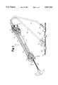
- FIG. 1is perspective view of the perfusion pump connected to a catheter manifold assembly, showing the flow path through the pump.
- FIG. 2is an exploded view of the components that make up the perfusion pump.
- FIG. 3is a cross sectional view of the pump taken along lines 3--3 of FIG. 1.
- FIG. 4is a cross section view of the preferred embodiment of the one way valve.
- FIG. 5is a bottom view of the one way valve show in FIG. 4.
- FIG. 6is a cross sectional view of another embodiment of a one way valve.
- FIG. 7is a cross sectional view of another embodiment of a one way valve.
- FIG. 1discloses the perfusion pump 10 connected to an catheter manifold assembly 12.
- FIG. 1discloses the perfusion pump 10 connected to an catheter manifold assembly 12.
- some of the internal cavities and conduits and of the distal manifold 14, proximal manifold 16 and the piston 24are shown as they may be seen if the components of the perfusion pump 10 were made of a clear plastic material.
- lines with arrowshave been included in FIG. 1 to trace the pathways that blood follows through the pump.
- the inlet and outlet tubes 32 and 34should be made from compliant material such as reinforced vinyl hose. It is important that tubes 32 and 34 be made from a material that will permit a small amount of expansion and contraction corresponding to the pulsation of the pump. This expansion and contraction functions to smooth out the peaks and valleys in the pulses.
- the balloon catheter 13is of the type that has a guide wire lumen that extends its entire length. Reference may be made to the U.S. Patent to Solar et al, U.S. Pat. No. 4,976,690 for a detailed disclosure of a balloon catheter of this type.
- the guide wirecan be removed and the guide wire lumen can then be used to pump blood through the balloon into the vessel beyond the stenoses.
- the balloon catheter 13extends through the mainport 40 of a Y-adapter 38 and out its distal end.
- a guide catheter 44is connected to the distal end of the Y-adapter 38 and is inserted percutaneously into the patients vessel.
- the inside diameter of the guide catheter 44is larger than the outside diameter of the balloon catheter's outer shaft 46, thus forming a coaxial lumen therebetween.
- the distal end of the guide catheter 44is open and blood from the patients can flow in the proximal direction through the coaxial lumen.
- This blood flow from the patientflows into the Y-adapter 38 and out its sideport 42.
- Swivel luer 34 and inlet tube 30are connected to sideport 42 and the blood stream from the patient thus flows through the Y-adapter 38 into the perfusion pump 10.
- FIG. 2is an exploded view of the perfusion pump 10 showing the component parts separated from each other along the longitudinal axis of the pump. In this view internal chambers and conduits of the component parts are visible and their structure and function will be made clear in the following discussion.
- distal splitter manifold 50When the perfusion pump 10 is assembled the distal splitter manifold 50, distal intermediate manifold 52, distal check manifold 54 and distal Y-manifold 56 are nested together and secured to each other by bonding or other connecting means. It should be noted that since pressurized fluid will be flowing through the cavities formed by this assembly of components the connection between the components must act to seal fluid flow between the components. It is also important that air not be permitted to enter the cavities in the perfusion pump 10 between the components. Although, not illustrated it is contemplated that self locking connecting means could be molded into the component parts such that they could snap together in the assembly process.
- distal component partsthat make up distal manifold 14 apply equally to the proximal end manifold 58, proximal intermediate manifold 60, proximal check manifold 62 and proximal Y-manifold 64 of the proximal manifold 16.
- the component partsshould be molded from a light strong material such as polycarbonate.
- the piston 24has a groove cut in its outer cylindrical surface for receipt of an o-ring 66.
- the o-ring 66provides a liquid seal between the piston 24 and the inner wall of the barrel or cylinder 22 so that when the piston 24 reciprocates in barrel or cylinder 22 fluid will not flow past piston 24.
- distal intermediate manifold 52 and proximal intermediate manifold 60are identical but face in opposite directions. As a result both ends of this identical component can be seen in FIG. 2.
- FIG. 2Referring first to the end of this component that is seen when looking at distal intermediate manifold 52.
- oval shaped opening 74In the lower half of the component there is an oval shaped opening 74 that extends partially through the component.
- a pair of downwardly diverging grooves 76 and 78are seen on the end seen when viewing proximal intermediate manifold 60 .
- These grooves 76 and 78have a semicircular cross section.
- the upper small diameter openings that open into tubing seats 70 and 72also open into the upper ends of grooves 76 and 78 and the lower small diameter openings 75 open into the lower ends of grooves 76 and 78.
- the distal ends of upper tubing 18 and 20are received in the tubing seats 70 and 72 of distal intermediate manifold 52.
- the proximal ends of upper tubing 18 and 20are received in the tubing seats 70 and 72 of proximal intermediate manifold 60.
- the upper tubing 18 and 20should be made from material such as acrylic tubing.
- the distal check manifold 54 and proximal check manifold 62are also identical and since they are turned to face each other both end faces are visible in FIG. 2.
- the end face of distal check manifold 54 seen in FIG. 2has an oval shaped opening 80 formed therein.
- Two check valve conduits 82 and 84visible when viewing proximal intermediate manifold 60, extend from the bottom of oval shaped opening 80 through the remainder of the component.
- the check valve conduits 82 and 84can be seen in the face of extension 86. It should be noted that oval shaped extensions 86 are received in the oval shaped openings 74 formed in distal intermediate manifold 52 and proximal intermediate manifold 60.
- the distal Y-manifold 56 and proximal Y-manifold 64are identical and thus both faces of this component are visible in FIG. 2.
- a cylinder seat 88In the visible face of distal Y-manifold 56 there is a cylinder seat 88.
- proximal Y-manifold 64In the face of proximal Y-manifold 64 that is seen there is an oval shaped extension 90 that has a slot 92 formed therein. Both ends of slot 92 communicate with cylinder seat 88.
- the proximal and distal ends of the barrel or cylinder 22are received in the cylinder seats 88.
- the distal manifold 14 and proximal manifold 16are connected by barrel or cylinder 22 and upper tubing 20 and 22.
- the distal splitter manifold 50 and proximal end manifold 58are similar but not identical.
- Identical groves 94 and 96are formed in the face of proximal end manifold 58 that is not visible in FIG. 2.
- Groves 94 and 96mate with groves 76 and 78 formed in distal intermediate manifold 52 and proximal intermediate manifold 60 such that together they form conduits having circular cross sections.
- connectorsare aligned with the upper ends of grooves 94 and 96.
- proximal end manifold 58there is an opening 98 from which the rod 26 extends.
- the opening 98is larger in diameter than rod 26 and the back ring 48 is received in this space.
- the back ring 48functions to provide a seal for the reciprocating rod 26.
- FIG. 3is a cross sectional view of the perfusion pump 10 taken along lines 3--3 of FIG. 1. This cross sectional view cuts through the valve conduits 82 and 84 that are formed in distal check manifold 54 and proximal check manifold 62. As can be seen in FIG. 3 the check valve conduit 84 of distal check manifold 54 functions as an input check valve. The input valve seat 102 is opened and closed by the ball valve 104. As can be seen in this view a portion of distal Y-manifold 56 cooperates with the valve seat 102 to form a cage that retains the ball valve 104.
- the check valve conduit 82 of distal check manifold 54functions as an output valve having a output valve seat 110 and a ball valve 112.
- a portion of the oval shaped opening 74 formed in distal intermediate manifold 52cooperates with valve seat 110 to form a cage for retaining the ball valve 112.
- the check valve conduit 82 in proximal check manifold 62functions as an inlet valve having a input valve seat 106 and a ball valve 108.
- a portion of proximal Y-manifold 64cooperates with the input valve seat 106 to form a cage for retaining the ball valve 108.
- the check valve conduit 84 in proximal check manifold 62functions as an outlet valve having a output valve seat 114 and a ball valve 116.
- the bottom of the oval shaped opening 74 formed in proximal intermediate manifold 60cooperates with output valve seat 114 to form a cage to retain ball valve 116.
- the piston 24 and connected rod 26are also visible in this view.
- the o-ring 66 that is carried in a grove formed in the cylindrical surface of piston 24provides a seal for piston 24 to prevent fluid flow past the piston 24.
- the back ring 48 and an o-ring 100function to seal the rod 26 to prevent liquid leakage at this point.
- perfusion pump 10Blood enters the perfusion pump 10 through the swivel luer 34 and travels through inlet tube 30 to the distal manifold 14. Blood flowing into distal manifold 14 can follow either pathway A or pathway B. When blood follows pathway A it leaves distal manifold 14 and flows through upper tubing 18 to the proximal manifold 16. The fluid flows down the conduit formed by groves 76 and 96. The flow then enters inlet check valve conduit 82, forces ball valve 108 off valve seat 106, and into a chamber 120 formed in proximal Y-manifold 64.
- piston 24 in the proximal directionalso created a pathway B flow of blood from inlet tube 30 down the conduit formed by groves 94 and 78 into the inlet conduit 84 where it forces ball valve 104 off valve seat 102 and then into chamber 122 which is formed in distal Y-manifold 56.
- the fluidthen flows from chamber 122 into the distal end of barrel or cylinder 22.
- the one way check valvesare all of the type in which a ball valve is restrained in a cage having a valve seat. When there is fluid flow through the cage toward the valve seat the ball valve seats on the valve seat and flow through the cage is stopped. When flow is in the opposite direction it forces the ball valve off the valve seat and permits fluid flow through the cage.
- FIG. 3there is no structural means, such as a spring, exerting a pressure on the ball valve in the direction toward the valve seat.
- a springexerting a pressure on the ball valve in the direction toward the valve seat.
- FIGS. 4 and 5another embodiment of a one way valve is illustrated.
- This embodimentrepresents the preferred embodiment.
- FIG. 4is a cross section view through the element forming the valve conduit 130 and the valve seat 132.
- the ball valve 134which is not shown in cross section, includes a T-shaped restrainer comprising a stem 136 and a cross bar 138.
- the stem 136is dimensioned such that at equilibrium the ball valve 136 is resting on valve seat 132 and is restrained from movement away therefrom.
- This one way check valveis designed such that when there is no flow through the valve conduit 130 there is a pre-load force on ball valve 134. This pre-load force should be in the range of 1-100 grams and preferable about 5 grams.
- the ball valve 136 with its integral T-shaped restraineris installed by pinching the free ends of cross bar 138 together such that they can pass through the restricted portion of valve conduit 130.
- the cross barwill spring back into its original shape, as seen in FIG. 4, after it is in place.
- the inlet side of the conduit 130is flared at 140 to provide a large entrance into the conduit 130.
- the cross bar 138extends across the flared inlet opening into conduit 130 and is seated on a flat surface 142. When there is fluid flow in the direction of the arrows in FIG. 4, the cross bar 138 bows up into the flared opening 140 of the inlet conduit thus permitting ball valve 134 to moved off valve seat 132 and allow flow through the one way valve.
- FIG. 5is a bottom view of FIG. 4 and it illustrates the relationships between the components of this one way valve.
- FIG. 6illustrates another embodiment of one way valve that could be used in the perfusion pump.
- a spring 150that could be stamped from sheet material, in engagement with the ball valve 152.
- Spring 150exerts a pre-load force on ball valve 152 causing it to set on valve seat 154. When this pre-load force is overcome the one way valve opens and fluid flows past the ball valve 152.
- this embodimentrequires a reaction surface 156 for spring 150.
- the spring 150 of this embodimenthas a pair of cantilever tabs that are permanently bent in the direction toward the ball valve. The spring 150 bears against reaction surface 156 and the free ends of the cantilevered tabs contact the ball valve 152.
- FIG. 7illustrates still another embodiment of a one way valve that could be used in the perfusion pump.
- this embodimentthere is a coil spring 160 in engagement with the ball valve 162 forcing it into contact with the valve seat 164.
- one end of coil spring 160engages a reaction surface 166 and the other end engages ball valve 160. This causes a pre-load force to be exerted on ball valve in the direction of valve seat 164.
- check valves included in this applicationall have spherical shaped valves it should be understood that the valve could have an ellipsoid, oval or other similar shape. Also it should be understood that other common types of one way valves such a rubber flap valve could be used as well as a ball type valve.
Landscapes
- Health & Medical Sciences (AREA)
- Heart & Thoracic Surgery (AREA)
- Vascular Medicine (AREA)
- Engineering & Computer Science (AREA)
- Anesthesiology (AREA)
- Biomedical Technology (AREA)
- Hematology (AREA)
- Life Sciences & Earth Sciences (AREA)
- Animal Behavior & Ethology (AREA)
- General Health & Medical Sciences (AREA)
- Public Health (AREA)
- Veterinary Medicine (AREA)
- Cardiology (AREA)
- External Artificial Organs (AREA)
Abstract
Description
Claims (22)
Priority Applications (1)
| Application Number | Priority Date | Filing Date | Title |
|---|---|---|---|
| US08/022,048US5407424A (en) | 1993-02-24 | 1993-02-24 | Angioplasty perfusion pump |
Applications Claiming Priority (1)
| Application Number | Priority Date | Filing Date | Title |
|---|---|---|---|
| US08/022,048US5407424A (en) | 1993-02-24 | 1993-02-24 | Angioplasty perfusion pump |
Publications (1)
| Publication Number | Publication Date |
|---|---|
| US5407424Atrue US5407424A (en) | 1995-04-18 |
Family
ID=21807543
Family Applications (1)
| Application Number | Title | Priority Date | Filing Date |
|---|---|---|---|
| US08/022,048Expired - Fee RelatedUS5407424A (en) | 1993-02-24 | 1993-02-24 | Angioplasty perfusion pump |
Country Status (1)
| Country | Link |
|---|---|
| US (1) | US5407424A (en) |
Cited By (20)
| Publication number | Priority date | Publication date | Assignee | Title |
|---|---|---|---|---|
| WO1999038560A1 (en) | 1998-02-03 | 1999-08-05 | Salient Interventional Systems, Inc. | Methods and systems for treating ischemia |
| WO2000006219A1 (en)* | 1998-07-28 | 2000-02-10 | Advanced Therapeutic Technologies At2 Inc. | Wound irrigation device |
| US6248087B1 (en) | 1997-08-15 | 2001-06-19 | Therox, Inc. | Apparatus for generalized extracorporeal support |
| US6295990B1 (en) | 1998-02-03 | 2001-10-02 | Salient Interventional Systems, Inc. | Methods and systems for treating ischemia |
| US6602071B1 (en)* | 2001-01-13 | 2003-08-05 | M. Edmund Ellion | Hand-held self-contained cleaning system |
| US6622367B1 (en) | 1998-02-03 | 2003-09-23 | Salient Interventional Systems, Inc. | Intravascular device and method of manufacture and use |
| US6884231B1 (en) | 2002-10-17 | 2005-04-26 | Hamilton Company | Dual chambered fluid displacement apparatus |
| US7008535B1 (en) | 2000-08-04 | 2006-03-07 | Wayne State University | Apparatus for oxygenating wastewater |
| US7172572B2 (en) | 2001-10-04 | 2007-02-06 | Boston Scientific Scimed, Inc. | Manifold system for a medical device |
| US20090204078A1 (en)* | 2008-02-13 | 2009-08-13 | Boston Scientific Scimed, Inc. | Manifold and Valve Seal for Use with a Medical Device |
| US20100318178A1 (en)* | 2009-06-15 | 2010-12-16 | Perflow Medical Ltd. | Method and apparatus for allowing blood flow through an occluded vessel |
| EP1539275A4 (en)* | 2002-07-29 | 2010-12-22 | Gore Enterprise Holdings Inc | Blood aspiration system and methods of use |
| US9956377B2 (en) | 2002-09-20 | 2018-05-01 | Angiodynamics, Inc. | Method and apparatus for intra-aortic substance delivery to a branch vessel |
| US10279112B2 (en) | 2012-09-24 | 2019-05-07 | Angiodynamics, Inc. | Power injector device and method of use |
| US10376274B2 (en) | 2015-07-16 | 2019-08-13 | Perflow Medical Ltd. | Apparatus and method for vessel occlusion removal |
| US11369739B2 (en) | 2013-01-21 | 2022-06-28 | Medline Industries, Lp | Method to provide injection system parameters for injecting fluid into patient |
| US11464949B2 (en) | 2018-04-12 | 2022-10-11 | The Regents Of The University Of Michigan | System for effecting and controlling oscillatory pressure within balloon catheters for fatigue fracture of calculi |
| US11619220B1 (en) | 2022-07-05 | 2023-04-04 | Wayne Richard Anderson | Continuous flow infusion pump utilizing angular aligned fingers |
| US20240075259A1 (en)* | 2022-09-06 | 2024-03-07 | Osama Amine | Balloon Angioplasty Inflation Device and Method of Preparing a Balloon for Angioplasty |
| US12279782B2 (en) | 2021-02-04 | 2025-04-22 | Amplitude Vascular Systems, Inc. | Pulsatile balloon catheter systems and methods of using the same |
Citations (107)
| Publication number | Priority date | Publication date | Assignee | Title |
|---|---|---|---|---|
| US167366A (en)* | 1875-08-31 | tyler | ||
| US407934A (en)* | 1889-07-30 | kiekwood | ||
| US443083A (en)* | 1890-12-16 | Syringe | ||
| US458774A (en)* | 1891-09-01 | Ridge | ||
| US497250A (en)* | 1893-05-09 | George s | ||
| US636118A (en)* | 1899-01-28 | 1899-10-31 | Mackie Lovejoy Mfg Company | Bicycle-pum. |
| US658325A (en)* | 1899-12-13 | 1900-09-18 | John M Stukes | Double-acting pump. |
| US679454A (en)* | 1901-04-01 | 1901-07-30 | George F Conner | Pump. |
| US717084A (en)* | 1902-04-03 | 1902-12-30 | J W Devero | Tire-setter. |
| US930312A (en)* | 1908-12-21 | 1909-08-03 | Frank A Neveu | Vaginal syringe. |
| DK15654C (en) | 1912-02-26 | William Snee | Pump for use in connection with wind motors and the like. | |
| US1029476A (en)* | 1912-04-15 | 1912-06-11 | George St Peters | Double-acting pump. |
| US1128089A (en)* | 1913-03-17 | 1915-02-09 | Fort Wayne Engineering And Mfg Company | Differential pump. |
| US1170661A (en)* | 1914-01-05 | 1916-02-08 | F E Myers And Brother | Pump. |
| US1223243A (en)* | 1916-06-15 | 1917-04-17 | Alfred N Bessesen | Syringe. |
| US1248230A (en)* | 1917-02-16 | 1917-11-27 | Ivor G Williams | Pump. |
| US1275440A (en)* | 1917-08-08 | 1918-08-13 | Harry O Johnson | Air-pump. |
| US1332293A (en)* | 1919-04-28 | 1920-03-02 | W D Coil | Air-pump |
| US1390559A (en)* | 1919-07-16 | 1921-09-13 | Jessie A Allen | Variable-power hand air-pump |
| US1392928A (en)* | 1920-06-08 | 1921-10-11 | Manton E Foss | Pump |
| US1527226A (en)* | 1921-07-13 | 1925-02-24 | Edward A Rollins | Pump |
| US1777195A (en)* | 1929-06-21 | 1930-09-30 | James C Cairncross | Double-acting pump |
| US1806268A (en)* | 1929-03-08 | 1931-05-19 | Stewart Warner Corp | Fuel pump |
| US1851802A (en)* | 1931-10-06 | 1932-03-29 | Magic City Specialty Company | Double acting deep well pump |
| US1880494A (en)* | 1930-02-24 | 1932-10-04 | Jacob R Sandage | Pump |
| US1930731A (en)* | 1932-12-14 | 1933-10-17 | Linde Air Prod Co | Method and apparatus for transferring liquid material |
| US1946559A (en)* | 1932-01-25 | 1934-02-13 | Edwin C Weiskopf | Dispensing device |
| US2018144A (en)* | 1933-04-29 | 1935-10-22 | Linde Air Prod Co | Method and apparatus for transferring gas material |
| US2057901A (en)* | 1934-11-15 | 1936-10-20 | John T Moore | Blood transfusion syringe |
| US2077774A (en)* | 1934-02-19 | 1937-04-20 | Fred F Rudder | Transfusion apparatus |
| US2290829A (en)* | 1939-09-29 | 1942-07-21 | Timken Roller Bearing Co | Fuel pump |
| US2338419A (en)* | 1940-07-25 | 1944-01-04 | Forrest William James | Filtering and like treatment of fluids |
| US2625115A (en)* | 1948-04-20 | 1953-01-13 | Harry P Maloney | Double-acting reciprocating pump |
| FR1030140A (en) | 1950-12-27 | 1953-06-10 | Eugene Dumont Ets | Double acting pump |
| US2702006A (en)* | 1950-06-12 | 1955-02-15 | Bachert Arthur | Means for delivering brine under pressure for injection pickling |
| US2972960A (en)* | 1957-03-21 | 1961-02-28 | Distillers Co Yeast Ltd | Liquid pumping apparatus |
| US2989227A (en)* | 1959-01-19 | 1961-06-20 | Statham Instrument Inc | Pneumatic pump |
| US3039399A (en)* | 1959-12-07 | 1962-06-19 | Foregger Company Inc | Pump |
| US3083648A (en)* | 1959-02-25 | 1963-04-02 | Superior Air Products Co | Liquefied gas pump |
| US3180096A (en)* | 1964-01-22 | 1965-04-27 | Williamson & Palmatier | Fluid pressure actuating system for use in power steering of outboard motors and the like |
| US3207083A (en)* | 1963-08-21 | 1965-09-21 | Lohry Kermit Dean | Pump |
| US3212280A (en)* | 1963-11-22 | 1965-10-19 | Air Prod & Chem | Volatile liquid pumping system |
| US3279391A (en)* | 1964-06-18 | 1966-10-18 | Electronic Communications | Ultra-high pressure piston pump |
| US3398743A (en)* | 1965-10-20 | 1968-08-27 | Shalit Shimon | Closed system irrigating apparatus for viscus organs |
| US3422765A (en)* | 1967-03-24 | 1969-01-21 | Gen Electric | Superconducting liquid helium pump |
| US3456648A (en)* | 1967-05-03 | 1969-07-22 | Lpt Corp | Automatic venous infusion monitoring apparatus |
| US3470823A (en)* | 1968-04-23 | 1969-10-07 | Seeger Wanner Corp | Crank means having an adjustable crank element |
| US3478956A (en)* | 1968-03-25 | 1969-11-18 | Charles E Gosha | Compressor |
| US3612731A (en)* | 1969-10-20 | 1971-10-12 | Keigo Tanemoto | Treadle-type pneumatic pump |
| US3692438A (en)* | 1969-10-21 | 1972-09-19 | Rodney E Schapel | Positive displacement pump |
| US3812854A (en)* | 1972-10-20 | 1974-05-28 | A Michaels | Ultrasonic nebulizer |
| US3817248A (en)* | 1972-11-06 | 1974-06-18 | Alza Corp | Self powered device for delivering beneficial agent |
| US3818907A (en)* | 1973-04-23 | 1974-06-25 | M Walton | Double cylinder lavage syringe |
| US3831600A (en)* | 1973-04-02 | 1974-08-27 | Alza Corp | Fluid flow control |
| US3840009A (en)* | 1971-12-27 | 1974-10-08 | Alza Corp | Self-powered vapor pressure delivery device |
| US3895631A (en)* | 1974-02-04 | 1975-07-22 | Alza Corp | Liquid infusion unit |
| US3990816A (en)* | 1971-11-09 | 1976-11-09 | Siemens Aktiengesellschaft | Double acting piston pump for cryogenic medium |
| US3993069A (en)* | 1973-03-26 | 1976-11-23 | Alza Corporation | Liquid delivery device bladder |
| US3994294A (en)* | 1975-02-28 | 1976-11-30 | Ivac Corporation | Syringe pump valving and motor direction control system |
| US4028017A (en)* | 1976-03-26 | 1977-06-07 | Kobiske Industries, Inc. | Manure pump having agitator piston |
| US4030495A (en)* | 1975-11-07 | 1977-06-21 | Baxter Travenol Laboratories, Inc. | Twin check valve pump system having fail-safe characteristic |
| US4054137A (en)* | 1976-07-02 | 1977-10-18 | Seung Joon Lee | Irrigator for body cavities |
| US4065230A (en)* | 1975-01-17 | 1977-12-27 | Hart Associates, Inc. | Reciprocating infusion pump and directional adapter set for use therewith |
| GB1496147A (en) | 1974-12-09 | 1977-12-30 | Eberspaecher J | Piston-type metering pumps |
| GB1496650A (en) | 1974-12-09 | 1977-12-30 | Eberspaecher J | Pistontype metering pumps |
| US4082095A (en)* | 1975-10-09 | 1978-04-04 | Barry Mendelson | Stomach pump |
| US4089634A (en)* | 1975-07-23 | 1978-05-16 | F. L. Smidth & Co. | Planetary cooler system for rotary kiln plant and the like |
| US4116115A (en)* | 1976-03-30 | 1978-09-26 | Wabco Westinghouse Gmbh | Bellows for sealing off the piston rod passage in an operating cylinder |
| US4140117A (en)* | 1975-05-12 | 1979-02-20 | Alza Corporation | Cartridge for liquid infusion apparatus |
| US4140118A (en)* | 1977-03-09 | 1979-02-20 | Andros Incorporated | Cassette chamber for intravenous delivery system |
| US4162616A (en)* | 1976-04-02 | 1979-07-31 | Tokico Ltd. | Hydraulic master cylinder |
| US4199307A (en)* | 1977-07-05 | 1980-04-22 | Andros Incorporated | Medical infusion system |
| US4201207A (en)* | 1973-03-26 | 1980-05-06 | Alza Corporation | Bladder for liquid dispenser |
| US4236880A (en)* | 1979-03-09 | 1980-12-02 | Archibald Development Labs, Inc. | Nonpulsating IV pump and disposable pump chamber |
| GB1600749A (en) | 1977-07-22 | 1981-10-21 | Willett Thomas & Co Ltd | Liquid dispensing systems |
| US4301811A (en)* | 1978-10-27 | 1981-11-24 | The Kendall Company | Cystometry system |
| US4326025A (en)* | 1979-12-19 | 1982-04-20 | Baxter Travenol Laboratories, Inc. | Anti-hemolytic agent emulsions and the use thereof |
| US4326510A (en)* | 1979-11-20 | 1982-04-27 | World Health Organization | Barrier contraceptive torus |
| US4334839A (en)* | 1978-09-22 | 1982-06-15 | Flagg Rodger H | Hand operated, dual chambered, pneumatic pump |
| US4336800A (en)* | 1980-08-01 | 1982-06-29 | Oximetrix, Inc. | Intravenous metering device |
| US4396385A (en)* | 1980-12-05 | 1983-08-02 | Baxter Travenol Laboratories, Inc. | Flow metering apparatus for a fluid infusion system |
| US4399099A (en)* | 1979-09-20 | 1983-08-16 | Buckles Richard G | Optical fiber apparatus for quantitative analysis |
| US4443163A (en)* | 1982-07-15 | 1984-04-17 | Gaither Luis A | Fluid motor or pump |
| US4453931A (en)* | 1980-08-01 | 1984-06-12 | Oximetrix, Inc. | Intravenous metering device |
| US4480969A (en)* | 1981-11-12 | 1984-11-06 | The Coca-Cola Company | Fluid operated double acting diaphragm pump housing and method |
| US4494447A (en)* | 1982-11-02 | 1985-01-22 | Westinghouse Electric Corp. | Self-latching eccentric cam for dual stroke compressor or pump |
| US4541455A (en)* | 1983-12-12 | 1985-09-17 | Tritec Industries, Inc. | Automatic vent valve |
| US4603593A (en)* | 1985-02-19 | 1986-08-05 | Clegg John E | Synchronized scotch yoke |
| US4643713A (en)* | 1984-11-05 | 1987-02-17 | Baxter Travenol Laboratories, Inc. | Venous reservoir |
| US4662868A (en)* | 1985-07-26 | 1987-05-05 | University Of Pittsburgh | Syringe apparatus and valve employed therein |
| US4734269A (en)* | 1985-06-11 | 1988-03-29 | American Hospital Supply Corporation | Venous reservoir bag with integral high-efficiency bubble removal system |
| US4771777A (en)* | 1987-01-06 | 1988-09-20 | Advanced Cardiovascular Systems, Inc. | Perfusion type balloon dilatation catheter, apparatus and method |
| US4784637A (en)* | 1987-03-23 | 1988-11-15 | Ryder International Corporation | Aseptic irrigation syringe |
| US4838860A (en)* | 1987-06-26 | 1989-06-13 | Pump Controller Corporation | Infusion pump |
| US4838866A (en)* | 1986-10-03 | 1989-06-13 | Marshall Sr William M | Liquid pump air release system |
| US4842581A (en)* | 1987-09-11 | 1989-06-27 | Davis Richard C | Medical lavage apparatus |
| US4865525A (en)* | 1986-09-19 | 1989-09-12 | Grunbeck Wasseraufbereitung Gmbh | Metering pump |
| US4872866A (en)* | 1987-09-11 | 1989-10-10 | Davis Richard C | Medical lavage apparatus |
| US4976690A (en)* | 1989-08-10 | 1990-12-11 | Scimed Life Systems, Inc. | Variable stiffness angioplasty catheter |
| US5013295A (en)* | 1988-03-25 | 1991-05-07 | Seymour Dubroff | Syringe for use in cataract surgery |
| US5049135A (en)* | 1990-09-18 | 1991-09-17 | Code Blue Medical Corporation | Medical lavage apparatus |
| US5066282A (en)* | 1987-09-23 | 1991-11-19 | Leocor, Inc. | Positive displacement piston driven blood pump |
| US5076769A (en)* | 1990-07-16 | 1991-12-31 | The Dow Chemical Company | Double acting pump |
| US5092844A (en)* | 1990-04-10 | 1992-03-03 | Mayo Foundation For Medical Education And Research | Intracatheter perfusion pump apparatus and method |
| US5106363A (en)* | 1988-10-11 | 1992-04-21 | Terumo Kabushiki Kaisha | Blood perfusion system and tube used therein |
| US5106500A (en) | 1990-06-20 | 1992-04-21 | Recovery Engineering, Inc. | Portable water purification system including a filter cleaning mechanism |
| US5158540A (en) | 1985-12-19 | 1992-10-27 | Leocor, Inc. | Perfusion catheter |
- 1993
- 1993-02-24USUS08/022,048patent/US5407424A/ennot_activeExpired - Fee Related
Patent Citations (107)
| Publication number | Priority date | Publication date | Assignee | Title |
|---|---|---|---|---|
| DK15654C (en) | 1912-02-26 | William Snee | Pump for use in connection with wind motors and the like. | |
| US407934A (en)* | 1889-07-30 | kiekwood | ||
| US443083A (en)* | 1890-12-16 | Syringe | ||
| US458774A (en)* | 1891-09-01 | Ridge | ||
| US497250A (en)* | 1893-05-09 | George s | ||
| US167366A (en)* | 1875-08-31 | tyler | ||
| US636118A (en)* | 1899-01-28 | 1899-10-31 | Mackie Lovejoy Mfg Company | Bicycle-pum. |
| US658325A (en)* | 1899-12-13 | 1900-09-18 | John M Stukes | Double-acting pump. |
| US679454A (en)* | 1901-04-01 | 1901-07-30 | George F Conner | Pump. |
| US717084A (en)* | 1902-04-03 | 1902-12-30 | J W Devero | Tire-setter. |
| US930312A (en)* | 1908-12-21 | 1909-08-03 | Frank A Neveu | Vaginal syringe. |
| US1029476A (en)* | 1912-04-15 | 1912-06-11 | George St Peters | Double-acting pump. |
| US1128089A (en)* | 1913-03-17 | 1915-02-09 | Fort Wayne Engineering And Mfg Company | Differential pump. |
| US1170661A (en)* | 1914-01-05 | 1916-02-08 | F E Myers And Brother | Pump. |
| US1223243A (en)* | 1916-06-15 | 1917-04-17 | Alfred N Bessesen | Syringe. |
| US1248230A (en)* | 1917-02-16 | 1917-11-27 | Ivor G Williams | Pump. |
| US1275440A (en)* | 1917-08-08 | 1918-08-13 | Harry O Johnson | Air-pump. |
| US1332293A (en)* | 1919-04-28 | 1920-03-02 | W D Coil | Air-pump |
| US1390559A (en)* | 1919-07-16 | 1921-09-13 | Jessie A Allen | Variable-power hand air-pump |
| US1392928A (en)* | 1920-06-08 | 1921-10-11 | Manton E Foss | Pump |
| US1527226A (en)* | 1921-07-13 | 1925-02-24 | Edward A Rollins | Pump |
| US1806268A (en)* | 1929-03-08 | 1931-05-19 | Stewart Warner Corp | Fuel pump |
| US1777195A (en)* | 1929-06-21 | 1930-09-30 | James C Cairncross | Double-acting pump |
| US1880494A (en)* | 1930-02-24 | 1932-10-04 | Jacob R Sandage | Pump |
| US1851802A (en)* | 1931-10-06 | 1932-03-29 | Magic City Specialty Company | Double acting deep well pump |
| US1946559A (en)* | 1932-01-25 | 1934-02-13 | Edwin C Weiskopf | Dispensing device |
| US1930731A (en)* | 1932-12-14 | 1933-10-17 | Linde Air Prod Co | Method and apparatus for transferring liquid material |
| US2018144A (en)* | 1933-04-29 | 1935-10-22 | Linde Air Prod Co | Method and apparatus for transferring gas material |
| US2077774A (en)* | 1934-02-19 | 1937-04-20 | Fred F Rudder | Transfusion apparatus |
| US2057901A (en)* | 1934-11-15 | 1936-10-20 | John T Moore | Blood transfusion syringe |
| US2290829A (en)* | 1939-09-29 | 1942-07-21 | Timken Roller Bearing Co | Fuel pump |
| US2338419A (en)* | 1940-07-25 | 1944-01-04 | Forrest William James | Filtering and like treatment of fluids |
| US2625115A (en)* | 1948-04-20 | 1953-01-13 | Harry P Maloney | Double-acting reciprocating pump |
| US2702006A (en)* | 1950-06-12 | 1955-02-15 | Bachert Arthur | Means for delivering brine under pressure for injection pickling |
| FR1030140A (en) | 1950-12-27 | 1953-06-10 | Eugene Dumont Ets | Double acting pump |
| US2972960A (en)* | 1957-03-21 | 1961-02-28 | Distillers Co Yeast Ltd | Liquid pumping apparatus |
| US2989227A (en)* | 1959-01-19 | 1961-06-20 | Statham Instrument Inc | Pneumatic pump |
| US3083648A (en)* | 1959-02-25 | 1963-04-02 | Superior Air Products Co | Liquefied gas pump |
| US3039399A (en)* | 1959-12-07 | 1962-06-19 | Foregger Company Inc | Pump |
| US3207083A (en)* | 1963-08-21 | 1965-09-21 | Lohry Kermit Dean | Pump |
| US3212280A (en)* | 1963-11-22 | 1965-10-19 | Air Prod & Chem | Volatile liquid pumping system |
| US3180096A (en)* | 1964-01-22 | 1965-04-27 | Williamson & Palmatier | Fluid pressure actuating system for use in power steering of outboard motors and the like |
| US3279391A (en)* | 1964-06-18 | 1966-10-18 | Electronic Communications | Ultra-high pressure piston pump |
| US3398743A (en)* | 1965-10-20 | 1968-08-27 | Shalit Shimon | Closed system irrigating apparatus for viscus organs |
| US3422765A (en)* | 1967-03-24 | 1969-01-21 | Gen Electric | Superconducting liquid helium pump |
| US3456648A (en)* | 1967-05-03 | 1969-07-22 | Lpt Corp | Automatic venous infusion monitoring apparatus |
| US3478956A (en)* | 1968-03-25 | 1969-11-18 | Charles E Gosha | Compressor |
| US3470823A (en)* | 1968-04-23 | 1969-10-07 | Seeger Wanner Corp | Crank means having an adjustable crank element |
| US3612731A (en)* | 1969-10-20 | 1971-10-12 | Keigo Tanemoto | Treadle-type pneumatic pump |
| US3692438A (en)* | 1969-10-21 | 1972-09-19 | Rodney E Schapel | Positive displacement pump |
| US3990816A (en)* | 1971-11-09 | 1976-11-09 | Siemens Aktiengesellschaft | Double acting piston pump for cryogenic medium |
| US3840009A (en)* | 1971-12-27 | 1974-10-08 | Alza Corp | Self-powered vapor pressure delivery device |
| US3812854A (en)* | 1972-10-20 | 1974-05-28 | A Michaels | Ultrasonic nebulizer |
| US3817248A (en)* | 1972-11-06 | 1974-06-18 | Alza Corp | Self powered device for delivering beneficial agent |
| US4201207A (en)* | 1973-03-26 | 1980-05-06 | Alza Corporation | Bladder for liquid dispenser |
| US3993069A (en)* | 1973-03-26 | 1976-11-23 | Alza Corporation | Liquid delivery device bladder |
| US3831600A (en)* | 1973-04-02 | 1974-08-27 | Alza Corp | Fluid flow control |
| US3818907A (en)* | 1973-04-23 | 1974-06-25 | M Walton | Double cylinder lavage syringe |
| US3895631A (en)* | 1974-02-04 | 1975-07-22 | Alza Corp | Liquid infusion unit |
| GB1496650A (en) | 1974-12-09 | 1977-12-30 | Eberspaecher J | Pistontype metering pumps |
| GB1496147A (en) | 1974-12-09 | 1977-12-30 | Eberspaecher J | Piston-type metering pumps |
| US4065230A (en)* | 1975-01-17 | 1977-12-27 | Hart Associates, Inc. | Reciprocating infusion pump and directional adapter set for use therewith |
| US3994294A (en)* | 1975-02-28 | 1976-11-30 | Ivac Corporation | Syringe pump valving and motor direction control system |
| US4140117A (en)* | 1975-05-12 | 1979-02-20 | Alza Corporation | Cartridge for liquid infusion apparatus |
| US4089634A (en)* | 1975-07-23 | 1978-05-16 | F. L. Smidth & Co. | Planetary cooler system for rotary kiln plant and the like |
| US4082095A (en)* | 1975-10-09 | 1978-04-04 | Barry Mendelson | Stomach pump |
| US4030495A (en)* | 1975-11-07 | 1977-06-21 | Baxter Travenol Laboratories, Inc. | Twin check valve pump system having fail-safe characteristic |
| US4028017A (en)* | 1976-03-26 | 1977-06-07 | Kobiske Industries, Inc. | Manure pump having agitator piston |
| US4116115A (en)* | 1976-03-30 | 1978-09-26 | Wabco Westinghouse Gmbh | Bellows for sealing off the piston rod passage in an operating cylinder |
| US4162616A (en)* | 1976-04-02 | 1979-07-31 | Tokico Ltd. | Hydraulic master cylinder |
| US4054137A (en)* | 1976-07-02 | 1977-10-18 | Seung Joon Lee | Irrigator for body cavities |
| US4140118A (en)* | 1977-03-09 | 1979-02-20 | Andros Incorporated | Cassette chamber for intravenous delivery system |
| US4199307A (en)* | 1977-07-05 | 1980-04-22 | Andros Incorporated | Medical infusion system |
| GB1600749A (en) | 1977-07-22 | 1981-10-21 | Willett Thomas & Co Ltd | Liquid dispensing systems |
| US4334839A (en)* | 1978-09-22 | 1982-06-15 | Flagg Rodger H | Hand operated, dual chambered, pneumatic pump |
| US4301811A (en)* | 1978-10-27 | 1981-11-24 | The Kendall Company | Cystometry system |
| US4236880A (en)* | 1979-03-09 | 1980-12-02 | Archibald Development Labs, Inc. | Nonpulsating IV pump and disposable pump chamber |
| US4399099A (en)* | 1979-09-20 | 1983-08-16 | Buckles Richard G | Optical fiber apparatus for quantitative analysis |
| US4326510A (en)* | 1979-11-20 | 1982-04-27 | World Health Organization | Barrier contraceptive torus |
| US4326025A (en)* | 1979-12-19 | 1982-04-20 | Baxter Travenol Laboratories, Inc. | Anti-hemolytic agent emulsions and the use thereof |
| US4336800A (en)* | 1980-08-01 | 1982-06-29 | Oximetrix, Inc. | Intravenous metering device |
| US4453931A (en)* | 1980-08-01 | 1984-06-12 | Oximetrix, Inc. | Intravenous metering device |
| US4396385A (en)* | 1980-12-05 | 1983-08-02 | Baxter Travenol Laboratories, Inc. | Flow metering apparatus for a fluid infusion system |
| US4480969A (en)* | 1981-11-12 | 1984-11-06 | The Coca-Cola Company | Fluid operated double acting diaphragm pump housing and method |
| US4443163A (en)* | 1982-07-15 | 1984-04-17 | Gaither Luis A | Fluid motor or pump |
| US4494447A (en)* | 1982-11-02 | 1985-01-22 | Westinghouse Electric Corp. | Self-latching eccentric cam for dual stroke compressor or pump |
| US4541455A (en)* | 1983-12-12 | 1985-09-17 | Tritec Industries, Inc. | Automatic vent valve |
| US4643713A (en)* | 1984-11-05 | 1987-02-17 | Baxter Travenol Laboratories, Inc. | Venous reservoir |
| US4603593A (en)* | 1985-02-19 | 1986-08-05 | Clegg John E | Synchronized scotch yoke |
| US4734269A (en)* | 1985-06-11 | 1988-03-29 | American Hospital Supply Corporation | Venous reservoir bag with integral high-efficiency bubble removal system |
| US4662868A (en)* | 1985-07-26 | 1987-05-05 | University Of Pittsburgh | Syringe apparatus and valve employed therein |
| US5158540A (en) | 1985-12-19 | 1992-10-27 | Leocor, Inc. | Perfusion catheter |
| US4865525A (en)* | 1986-09-19 | 1989-09-12 | Grunbeck Wasseraufbereitung Gmbh | Metering pump |
| US4838866A (en)* | 1986-10-03 | 1989-06-13 | Marshall Sr William M | Liquid pump air release system |
| US4771777A (en)* | 1987-01-06 | 1988-09-20 | Advanced Cardiovascular Systems, Inc. | Perfusion type balloon dilatation catheter, apparatus and method |
| US4784637A (en)* | 1987-03-23 | 1988-11-15 | Ryder International Corporation | Aseptic irrigation syringe |
| US4838860A (en)* | 1987-06-26 | 1989-06-13 | Pump Controller Corporation | Infusion pump |
| US4842581A (en)* | 1987-09-11 | 1989-06-27 | Davis Richard C | Medical lavage apparatus |
| US4872866A (en)* | 1987-09-11 | 1989-10-10 | Davis Richard C | Medical lavage apparatus |
| US5066282A (en)* | 1987-09-23 | 1991-11-19 | Leocor, Inc. | Positive displacement piston driven blood pump |
| US5013295A (en)* | 1988-03-25 | 1991-05-07 | Seymour Dubroff | Syringe for use in cataract surgery |
| US5106363A (en)* | 1988-10-11 | 1992-04-21 | Terumo Kabushiki Kaisha | Blood perfusion system and tube used therein |
| US4976690A (en)* | 1989-08-10 | 1990-12-11 | Scimed Life Systems, Inc. | Variable stiffness angioplasty catheter |
| US5092844A (en)* | 1990-04-10 | 1992-03-03 | Mayo Foundation For Medical Education And Research | Intracatheter perfusion pump apparatus and method |
| US5106500A (en) | 1990-06-20 | 1992-04-21 | Recovery Engineering, Inc. | Portable water purification system including a filter cleaning mechanism |
| US5076769A (en)* | 1990-07-16 | 1991-12-31 | The Dow Chemical Company | Double acting pump |
| US5049135A (en)* | 1990-09-18 | 1991-09-17 | Code Blue Medical Corporation | Medical lavage apparatus |
Cited By (34)
| Publication number | Priority date | Publication date | Assignee | Title |
|---|---|---|---|---|
| US6607698B1 (en)* | 1997-08-15 | 2003-08-19 | Therox, Inc. | Method for generalized extracorporeal support |
| US6248087B1 (en) | 1997-08-15 | 2001-06-19 | Therox, Inc. | Apparatus for generalized extracorporeal support |
| US6746417B2 (en) | 1997-08-15 | 2004-06-08 | Therox Inc | Apparatus for generalized extracorporeal support |
| US6044845A (en)* | 1998-02-03 | 2000-04-04 | Salient Interventional Systems, Inc. | Methods and systems for treating ischemia |
| US6295990B1 (en) | 1998-02-03 | 2001-10-02 | Salient Interventional Systems, Inc. | Methods and systems for treating ischemia |
| US6436087B1 (en) | 1998-02-03 | 2002-08-20 | Salient Interventional Systems, Inc. | Methods and systems for treating ischemia |
| US6435189B1 (en) | 1998-02-03 | 2002-08-20 | Salient Interventional Systems, Inc. | Methods and systems for treating ischemia |
| US6481439B1 (en) | 1998-02-03 | 2002-11-19 | Salient Interventional Systems, Inc. | Methods and systems for treating ischemia |
| WO1999038560A1 (en) | 1998-02-03 | 1999-08-05 | Salient Interventional Systems, Inc. | Methods and systems for treating ischemia |
| US6622367B1 (en) | 1998-02-03 | 2003-09-23 | Salient Interventional Systems, Inc. | Intravascular device and method of manufacture and use |
| WO2000006219A1 (en)* | 1998-07-28 | 2000-02-10 | Advanced Therapeutic Technologies At2 Inc. | Wound irrigation device |
| US7008535B1 (en) | 2000-08-04 | 2006-03-07 | Wayne State University | Apparatus for oxygenating wastewater |
| US7294278B2 (en) | 2000-08-04 | 2007-11-13 | Wayne State University | Method for oxygenating wastewater |
| US6602071B1 (en)* | 2001-01-13 | 2003-08-05 | M. Edmund Ellion | Hand-held self-contained cleaning system |
| US7172572B2 (en) | 2001-10-04 | 2007-02-06 | Boston Scientific Scimed, Inc. | Manifold system for a medical device |
| EP1539275A4 (en)* | 2002-07-29 | 2010-12-22 | Gore Enterprise Holdings Inc | Blood aspiration system and methods of use |
| US9956377B2 (en) | 2002-09-20 | 2018-05-01 | Angiodynamics, Inc. | Method and apparatus for intra-aortic substance delivery to a branch vessel |
| US6884231B1 (en) | 2002-10-17 | 2005-04-26 | Hamilton Company | Dual chambered fluid displacement apparatus |
| US20090204078A1 (en)* | 2008-02-13 | 2009-08-13 | Boston Scientific Scimed, Inc. | Manifold and Valve Seal for Use with a Medical Device |
| US11179253B2 (en) | 2009-06-15 | 2021-11-23 | Perflow Medieal Ltd. | Method and apparatus for allowing blood flow through an occluded vessel |
| US9510855B2 (en) | 2009-06-15 | 2016-12-06 | Perflow Medical Ltd. | Method and apparatus for allowing blood flow through an occluded vessel |
| US20100318178A1 (en)* | 2009-06-15 | 2010-12-16 | Perflow Medical Ltd. | Method and apparatus for allowing blood flow through an occluded vessel |
| US9278201B2 (en) | 2009-06-15 | 2016-03-08 | Perflow Medical Ltd. | Method and apparatus for allowing blood flow through an occluded vessel |
| US10279112B2 (en) | 2012-09-24 | 2019-05-07 | Angiodynamics, Inc. | Power injector device and method of use |
| US11369739B2 (en) | 2013-01-21 | 2022-06-28 | Medline Industries, Lp | Method to provide injection system parameters for injecting fluid into patient |
| US11129631B2 (en) | 2015-07-16 | 2021-09-28 | Perflow Medical Ltd. | Apparatus and method for vessel occlusion removal |
| US10376274B2 (en) | 2015-07-16 | 2019-08-13 | Perflow Medical Ltd. | Apparatus and method for vessel occlusion removal |
| US11464949B2 (en) | 2018-04-12 | 2022-10-11 | The Regents Of The University Of Michigan | System for effecting and controlling oscillatory pressure within balloon catheters for fatigue fracture of calculi |
| US12005210B2 (en) | 2018-04-12 | 2024-06-11 | The Regents Of The University Of Michigan | System for effecting and controlling oscillatory pressure within balloon catheters for fatigue fracture of calculi |
| US12279782B2 (en) | 2021-02-04 | 2025-04-22 | Amplitude Vascular Systems, Inc. | Pulsatile balloon catheter systems and methods of using the same |
| US12329400B2 (en) | 2021-02-04 | 2025-06-17 | Amplitude Vascular Systems, Inc. | Pulsatile balloon catheter systems and methods of using the same |
| US11619220B1 (en) | 2022-07-05 | 2023-04-04 | Wayne Richard Anderson | Continuous flow infusion pump utilizing angular aligned fingers |
| US20240075259A1 (en)* | 2022-09-06 | 2024-03-07 | Osama Amine | Balloon Angioplasty Inflation Device and Method of Preparing a Balloon for Angioplasty |
| US12329920B2 (en)* | 2022-09-06 | 2025-06-17 | Osama Amine | Balloon angioplasty inflation device and method of preparing a balloon for angioplasty |
Similar Documents
| Publication | Publication Date | Title |
|---|---|---|
| US5407424A (en) | Angioplasty perfusion pump | |
| EP0830533B1 (en) | Valve assembly | |
| US5378229A (en) | Check valve manifold assembly for use in angioplasty | |
| US4515589A (en) | Peristaltic pumping method and apparatus | |
| US5066282A (en) | Positive displacement piston driven blood pump | |
| US5419770A (en) | Self priming tubing set for an infusion device | |
| US4995864A (en) | Dual chamber pumping apparatus | |
| US4038983A (en) | Fluid infusion pump | |
| US6843780B2 (en) | Valve arrangement | |
| US4346704A (en) | Sleeve valve for parenteral solution device | |
| US5396925A (en) | Anti-free flow valve, enabling fluid flow as a function of pressure and selectively opened to enable free flow | |
| US4041944A (en) | Body fluid transfusion and displacement apparatus and method | |
| US7267669B2 (en) | Two site infusion apparatus | |
| RU2312684C2 (en) | Needle-free medical connector and method for regulating of liquid flow | |
| US4846806A (en) | Implantable intravascular access system | |
| US6273133B1 (en) | Fluid flow rate switching device | |
| RU2201263C2 (en) | Dropper, pumping system and method for sequentially supplying two liquids from a pair of containers to a patient | |
| US5217432A (en) | Automated drug infusion manifold | |
| CN104066986B (en) | Tubing pump | |
| RU99100056A (en) | DROPPER, PUMPING SYSTEM AND METHOD FOR SEQUENTIAL DELIVERY OF TWO LIQUIDS FROM A PAIR OF CONTAINERS TO A PATIENT | |
| US20030191453A1 (en) | Catheter assembly | |
| JPH05253295A (en) | Discharge injector with precision | |
| JPS6318060B2 (en) | ||
| US12029878B2 (en) | Peristaltic pump of an infusion system for delivery of small volumes of fluid |
Legal Events
| Date | Code | Title | Description |
|---|---|---|---|
| AS | Assignment | Owner name:SCIMED LIFE SYSTEMS, INC., MINNESOTA Free format text:ASSIGNMENT OF ASSIGNORS INTEREST;ASSIGNORS:LAFONTAINE, DANIEL M.;HOLMAN, THOMAS J.;ADAMS, DANIEL O.;REEL/FRAME:006546/0080 Effective date:19930421 | |
| FEPP | Fee payment procedure | Free format text:PAYOR NUMBER ASSIGNED (ORIGINAL EVENT CODE: ASPN); ENTITY STATUS OF PATENT OWNER: LARGE ENTITY | |
| FPAY | Fee payment | Year of fee payment:4 | |
| FEPP | Fee payment procedure | Free format text:PAYER NUMBER DE-ASSIGNED (ORIGINAL EVENT CODE: RMPN); ENTITY STATUS OF PATENT OWNER: LARGE ENTITY Free format text:PAYOR NUMBER ASSIGNED (ORIGINAL EVENT CODE: ASPN); ENTITY STATUS OF PATENT OWNER: LARGE ENTITY | |
| FPAY | Fee payment | Year of fee payment:8 | |
| REMI | Maintenance fee reminder mailed | ||
| AS | Assignment | Owner name:BOSTON SCIENTIFIC SCIMED, INC., MINNESOTA Free format text:CHANGE OF NAME;ASSIGNOR:SCIMED LIFE SYSTEMS, INC.;REEL/FRAME:018505/0868 Effective date:20050101 Owner name:BOSTON SCIENTIFIC SCIMED, INC.,MINNESOTA Free format text:CHANGE OF NAME;ASSIGNOR:SCIMED LIFE SYSTEMS, INC.;REEL/FRAME:018505/0868 Effective date:20050101 | |
| LAPS | Lapse for failure to pay maintenance fees | ||
| STCH | Information on status: patent discontinuation | Free format text:PATENT EXPIRED DUE TO NONPAYMENT OF MAINTENANCE FEES UNDER 37 CFR 1.362 | |
| FP | Lapsed due to failure to pay maintenance fee | Effective date:20070418 |