US5407420A - Fully adjustable shoulder brace - Google Patents
Fully adjustable shoulder braceDownload PDFInfo
- Publication number
- US5407420A US5407420AUS07/975,608US97560892AUS5407420AUS 5407420 AUS5407420 AUS 5407420AUS 97560892 AUS97560892 AUS 97560892AUS 5407420 AUS5407420 AUS 5407420A
- Authority
- US
- United States
- Prior art keywords
- shoulder
- rotation
- joint
- upper arm
- flexion
- Prior art date
- Legal status (The legal status is an assumption and is not a legal conclusion. Google has not performed a legal analysis and makes no representation as to the accuracy of the status listed.)
- Expired - Lifetime
Links
Images


Classifications
- A—HUMAN NECESSITIES
- A61—MEDICAL OR VETERINARY SCIENCE; HYGIENE
- A61F—FILTERS IMPLANTABLE INTO BLOOD VESSELS; PROSTHESES; DEVICES PROVIDING PATENCY TO, OR PREVENTING COLLAPSING OF, TUBULAR STRUCTURES OF THE BODY, e.g. STENTS; ORTHOPAEDIC, NURSING OR CONTRACEPTIVE DEVICES; FOMENTATION; TREATMENT OR PROTECTION OF EYES OR EARS; BANDAGES, DRESSINGS OR ABSORBENT PADS; FIRST-AID KITS
- A61F5/00—Orthopaedic methods or devices for non-surgical treatment of bones or joints; Nursing devices ; Anti-rape devices
- A61F5/01—Orthopaedic devices, e.g. long-term immobilising or pressure directing devices for treating broken or deformed bones such as splints, casts or braces
- A61F5/04—Devices for stretching or reducing fractured limbs; Devices for distractions; Splints
- A61F5/05—Devices for stretching or reducing fractured limbs; Devices for distractions; Splints for immobilising
- A61F5/058—Splints
- A61F5/05841—Splints for the limbs
- A61F5/05858—Splints for the limbs for the arms
- A—HUMAN NECESSITIES
- A61—MEDICAL OR VETERINARY SCIENCE; HYGIENE
- A61F—FILTERS IMPLANTABLE INTO BLOOD VESSELS; PROSTHESES; DEVICES PROVIDING PATENCY TO, OR PREVENTING COLLAPSING OF, TUBULAR STRUCTURES OF THE BODY, e.g. STENTS; ORTHOPAEDIC, NURSING OR CONTRACEPTIVE DEVICES; FOMENTATION; TREATMENT OR PROTECTION OF EYES OR EARS; BANDAGES, DRESSINGS OR ABSORBENT PADS; FIRST-AID KITS
- A61F5/00—Orthopaedic methods or devices for non-surgical treatment of bones or joints; Nursing devices ; Anti-rape devices
- A61F5/01—Orthopaedic devices, e.g. long-term immobilising or pressure directing devices for treating broken or deformed bones such as splints, casts or braces
- A61F5/0102—Orthopaedic devices, e.g. long-term immobilising or pressure directing devices for treating broken or deformed bones such as splints, casts or braces specially adapted for correcting deformities of the limbs or for supporting them; Ortheses, e.g. with articulations
- A61F5/013—Orthopaedic devices, e.g. long-term immobilising or pressure directing devices for treating broken or deformed bones such as splints, casts or braces specially adapted for correcting deformities of the limbs or for supporting them; Ortheses, e.g. with articulations for the arms, hands or fingers
Definitions
- the present inventionrelates to an orthopedic shoulder brace, and particularly to an adjustable orthopedic shoulder brace having a plurality of rotatable and lockable joints for positioning the shoulder at selected angles of abduction, flexion and rotation.
- a common means of immobilizing the damaged shoulder during rehabilitation thereofis to place the arm connected to the damaged shoulder in a sling and secure the sling to the torso of the patient by a strap. Although the secured sling effectively immobilizes the shoulder, the sling only enables immobilizing the shoulder in essentially one position against the body.
- the shoulderis a relatively complex body joint having several ranges of angular motion, i.e., abduction, flexion and rotation. It has been found that effective rehabilitation of the shoulder requires attention to positioning of the shoulder with respect to all of these ranges of angular shoulder motion. Accordingly, it is desirable to immobilize the shoulder in a manner that provides for adjustment of the shoulder position throughout the rehabilitation.
- a body cast enclosing the arm, shoulder and torsohas been used for selectively positioning the shoulder at abduction, flexion and rotation angles other than those afforded by a sling.
- a body castis extremely uncomfortable to the patient and cannot be adjusted to other positions without entirely recasting the patient.
- body castsunduly limit certain desired mobility of the patient, otherwise detracting from rehabilitation of the shoulder.
- body castshinder the ability of the patient to maintain good personal hygiene because they obstruct access to the axilla.
- the braceemploys anterior and posterior rigid support bars which extend from the hip of the patient to the axilla where each is joined anteriorly and posteriorly by selectively rotatable and lockable joints to anterior and posterior rigid support bars extending the length of the upper arm.
- this braceprovides obvious advantages over a sling or a cast, it has nevertheless been found to be uncomfortable for the patient to wear for long periods of time, particularly when sitting against a back support or sleeping on the back because of the rigid posterior components. Furthermore, the brace does not provide for adjustment of the shoulder flexion or rotation angles during rehabilitation.
- the present inventionis a fully adjustable orthopedic shoulder brace for stabilizing and immobilizing the shoulder of a patient in furtherance of the objects set forth above.
- the bracehas specific utility for rehabilitation of the shoulder following an injury or surgical trauma, and in particular following an injury or surgical trauma to the soft tissue of the shoulder.
- the shoulder bracemaintains the shoulder relatively comfortably and unobtrusively in a fixed, yet adjustable, position that facilitates rehabilitation of the shoulder throughout the healing period, and particularly during the acute rehabilitation phase immediately following an injury or surgery.
- the adjustable shoulder brace of the present inventionis mountable on the arm and torso of a human patient to isolate the connective shoulder therebetween.
- the body-mounted braceis fully adjustable across the three ranges of motion of the shoulder, i.e., abduction, flexion and rotation, to enable fixation of the shoulder in virtually any rehabilitative position.
- the braceis a support assembly comprising a series of rigid support members secured to the body of the patient, and a plurality of selectively rotatable and lockable joints adjustably interconnecting the support members. Although each joint is only rotatable within a single plane, the combination of three such joints in series simulates the entire range of motion of the shoulder.
- the components of the braceare described hereafter in the context of the body parts with which they align and interact.
- the support membersinclude a rigid torso bar and a rigid upper arm linkage.
- the torso barhas a hip cuff attached to it which, in concert with a plurality of straps, secures the distal end of the torso bar to the hip of the patient, thereby maintaining the torso bar in a fixed position relative to the torso.
- the secured torso baraccordingly extends from the hip to the axilla.
- the upper arm linkagesimilarly has a cuff attached to it which, in concert with a plurality of straps, secures the upper arm linkage to the underside of the upper arm, thereby maintaining the upper arm linkage in a fixed position relative to the upper arm.
- the secured upper arm linkageextends from the axilla to the elbow along the underside of the upper arm.
- the proximal end of the torso bar and the proximal end of the upper arm linkageare adjustably connected to one another across an axilla joint assembly positioned anterior to the body at or near the axilla.
- the axilla joint assemblyis made up of a shoulder abduction joint and a shoulder flexion joint in series with the abduction joint being adjacent to the torso bar and the flexion joint being adjacent to the upper arm linkage.
- the shoulder abduction jointhas a lock mode and a rotation mode of operation.
- the abduction jointIn the rotation mode, the abduction joint is freely rotatable about an axis of abduction rotation to any one of a plurality of shoulder abduction angles in the plane of rotation.
- the abduction jointcan be fixed in a selected shoulder abduction angle when switched from the rotation mode to the lock mode.
- the shoulder flexion jointlikewise has a lock mode and a rotation mode of operation.
- the flexion jointIn the rotation mode, the flexion joint is freely rotatable about an axis of flexion rotation to any one of a plurality of shoulder flexion angles in the plane of rotation.
- the flexion jointis fixed in the selected shoulder flexion angle when switched to the lock mode.
- the abduction and flexion jointsare fixably positioned relative to each other such that the planes of abduction and flexion rotation are at all times aligned substantially perpendicular to each other.
- the axes of abduction and flexion rotationare likewise aligned perpendicular to each other.
- the axis of abduction rotationis also aligned perpendicular to the longitudinal axis of its adjacent support member, the torso bar, and similarly the axis of flexion rotation is aligned perpendicular to the longitudinal axis of its adjacent support member, the upper arm linkage.
- a shoulder rotation jointis further provided integral with the upper arm linkage.
- the shoulder rotation jointhas a lock mode and a rotation mode of operation. In the rotation mode, the joint is freely rotatable about an axis of rotator rotation to any one of a plurality of angles in the plane of rotation. The rotation joint is fixed in the selected shoulder rotator angle when switched from the rotation mode to the lock mode.
- the shoulder rotation jointhas an axis of rotation that is collinear with the longitudinal axis of its adjacent support member, the upper arm linkage. It is further noted that the axis of shoulder rotator rotation is aligned substantially perpendicular to the axis of shoulder flexion rotation at all times.
- the support membersfurther includes a forearm bar.
- the forearm barhas a cuff attached to it which, in concert with a plurality of straps, secures the forearm bar to the underside of the forearm, thereby maintaining the forearm bar in a fixed position relative to the forearm.
- the secured forearm barextends from the elbow to the wrist along the underside of the forearm.
- the distal end of the upper arm linkage and the proximal end of the forearm barare adjustably connected to one another across an elbow flexion joint having a configuration and operating modes similar to the shoulder abduction and flexion joints.
- the elbow flexion jointis, thus, freely rotatable in the rotation mode and fixable at a selected elbow flexion angle in the lock mode.
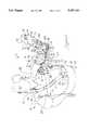
- FIG. 1is an anterior perspective view of the adjustable shoulder brace of the present invention mounted on the body of a patient.
- FIG. 2is a posterior perspective view of the adjustable shoulder brace of FIG. 1 mounted on the patient.
- FIG. 3is an exploded perspective view of the support assembly of the adjustable shoulder brace of FIG. 1.
- FIGS. 4A and 4Bare an exploded perspective view of the rotatable and lockable joints of the adjustable shoulder brace of FIG. 1 divided into two figures at the junction of the axilla joint assembly and the upper arm linkage.
- FIG. 5is a diagrammatic view of the adjustable axes and planes of rotation enabled by the shoulder brace of the present invention.
- the adjustable shoulder brace of the present inventionis shown mounted on the body 12 of a patient.
- the brace 10is described hereafter with the shoulder 14a serving as a reference point, such that elements of the brace 10 located near the shoulder 14a are termed “proximal” and elements of the brace 10 located away from the shoulder 14a are termed “distal”.
- proximalelements of the brace 10 located near the shoulder 14a
- distalelements of the brace 10 located away from the shoulder 14a
- the brace 10 described hereafteris configured for rehabilitative treatment of the shoulder 14a, it is apparent to one skilled in the art that the brace 10 can be readily adapted for similar rehabilitative treatment of the opposite shoulder 14b.
- the brace 10is mounted on the body 12 by means of a support assembly comprising a plurality of cuffs, including a hip cuff 16 formed from a stiffened sheet of plastic that is nevertheless sufficiently flexible to conform to the contour of the hip 18 engaged by the cuff 16.
- a foam hip pad 20is positioned between the hip 18 and hip cuff 16 for the comfort of the patient.
- the hip pad 20is attached to the hip cuff 16 by a conventional hook and loop fastener, commonly termed a VELCRO fastener.
- a padded belt 22is tightly fastened around the midsection of the patient over the hip cuff 16 and pad 20, thereby pressing the cuff 16 and pad 20 firmly against the hip 18 in conformance therewith to secure the brace 10 at the hip 18.
- the belt 22is fastened to itself and to the hip cuff 16 by means of VELCRO fasteners.
- the brace 10is further secured to the body 12 at the upper arm 24 and forearm 26 of the patient.
- An upper arm cuff 28is provided to engage the upper arm 24.
- the upper arm cuff 28, like the hip cuff 16,is formed from a stiffened sheet of plastic that is conformable to the body contours engaged by the cuff 28.
- the cuff 28is also provided with an upper arm foam pad 30 that is positioned between the upper arm 24 and cuff 28 and is attached to the upper arm cuff 28 by a VELCRO fastener.
- a pair of flexible cloth upper arm straps 32a, 32bare threaded through slots 34 in the cuff 28 and tightly fastened around the upper arm 24 over the cuff 28 and pad 30, thereby pressing the cuff 28 and pad 30 firmly against the upper arm 24 in conformance therewith to secure the brace 10 at the upper arm 24.
- the straps 32a, 32bare fastened to themselves and to the upper arm cuff 28 by means of VELCRO fasteners.
- a forearm cuff 36is provided to engage the forearm 26.
- the forearm cuff 36is formed from a rigid sheet of metal that is preformed to conform to the body contours engaged by the cuff 36.
- the forearm cuff 36is provided with a foam forearm pad 38 that is positioned between the forearm 26 and attached to the forearm cuff 36 by a VELCRO fastener.
- a spherical foam hand bolster 40is attached to the distal end of the forearm cuff 36 to provide support for the hand 42.
- the bolster 40also provides a means for exercising the arm while the shoulder 14a is immobilized by firmly gripping the bolster 40 with the hand 42.
- a pair of flexible cloth forearm straps 44a, 44bare threaded through slots 46 in the cuff 36 and tightly fastened around the forearm 26 over the cuff 36 and pad 38, thereby pressing the cuff 36 and pad 38 firmly against the forearm 26 to secure the brace 10 at the forearm 26.
- the straps 44a, 44bare fastened to themselves and to the forearm cuff 36 by means of VELCRO fasteners.
- cuffs 16, 28, and 36are interconnected by means of a plurality of rigid support members joined across a plurality of selectively rotatable and lockable joints.
- a rigid torso bar 48formed from a strong lightweight material, such as aluminum or a composite, is distally attached to the hip cuff 16 and extends upward from the hip 18 along the anterior of the torso 50 to the anterior of the axilla 52.
- Adjustable attachment of the torso bar 48 to the hip cuff 16is provided in a manner described hereafter to enable fitting of the brace 10 to different body sizes.
- a rigid metal upper arm linkage 54is attached to the upper arm cuff 28 in a freely rotatable manner by means of a rotatable mounting assembly 56.
- the linkage 54extends away from the axilla 52 along the underside of the upper arm 24 to the elbow 58.
- the linkage 54comprises a female bar 60 having a male bar 62 extending therefrom to provide telescopic adjustment of the length of the linkage 54 in a manner described hereafter, thereby enabling fitting of the brace 10 to different arm lengths.
- a rigid metal forearm bar 64is attached to the forearm cuff 36 and extends away from the elbow 58 along the underside of the forearm 26 to the wrist 66.
- Adjustable attachment of the forearm bar 64 to the forearm cuff 36is provided by selectively releasable knobs 68a, 68b in a manner described hereafter to further enable fitting of the brace 10 to different arm lengths.
- a joint assembly 70proximally joins the torso bar 48 to the upper arm linkage 54 at the anterior of the body 12 near the axilla 52.
- the joint assembly 70comprises a shoulder abduction joint 72 at the proximal end of the torso bar 48 and a shoulder flexion joint 74 at the proximal end of the upper arm linkage 54.
- the joints 72 and 74are orthogonally connected across a union member 76.
- a shoulder rotation joint 78 integral with the upper arm linkage 54is further to rotatably connect the female bar 60 and the male bar 62.
- an elbow flexion joint 80joins the distal end of the upper arm linkage 54 to the proximal end of the forearm bar 64 at the underside of the elbow 58.
- a foam pad 82is positioned between the shoulder abduction joint 72 and the axilla 52, and is attached to underside of the abduction joint 72 by a VELCRO fastener.
- a fleece-covered foam pad 84is positioned between the elbow flexion joint 80 and the elbow 58 and is attached to the underside of the joint 80 by a VELCRO fastener.
- a foam pad 86is also fitted around the torso bar 48 for the comfort of the patient.
- the shoulder strap 88passes through a first strap loop 92a riveted to one edge of the hip cuff 16, over the opposite shoulder 14b of the patient, and through a second strap loop 92b riveted to the opposite edge of the hip cuff 16 as shown in FIG. 2.
- a foam pad 94is provided around the strap 88 where it engages the shoulder 14b for the comfort of the patient.
- the strap 88is fastened onto itself by VELCRO tabs attached to its ends.
- the chest strap 90passes through a first strap loop 96a riveted to one edge of the torso bar 48, around the chest 98 of the patient, and through a second strap loop 96b riveted to the opposite edge of the torso bar 48.
- a foam pad 100is provided around the strap 90 where it engages the right side of the chest 98.
- the strap 90is fastened onto itself by VELCRO attached to its ends. Straps 88, 90 overlap on the anterior side of the patient and are secured to one another at the point of overlap by a VELCRO strip 101.
- FIG. 2shows the posterior configuration of the brace 10. It is apparent from FIG. 2 that the posterior of the brace 10 is substantially free of any rigid structural components, thereby enabling the patient to recline or sit posteriorly with a minimum of discomfort. The posterior configuration also provides unobstructed access to the axilla 52 for improved personal hygiene during extended periods of use of the brace 10.
- the support assemblyis shown to comprise the torso bar 48, upper arm linkage 54 and forearm bar 64, connected to the hip cuff 16, upper arm cuff 28, and forearm cuff 36, respectively.
- Adjustable connection of the torso bar 48 to the hip cuff 16is provided by a mounting bracket 102 riveted to the hip cuff 16.
- a longitudinal slot 104is formed in the mounting bracket 102 to receive a threaded male member 106.
- the male member 106extends away from the body through the slot 104, through a swivel-prevention bracket 108 slidably positioned over the mounting bracket 102, and through a distal aperture 110 in the torso bar 48.
- An adjustment knob 112having corresponding female threads is threadably attached to the end of the male member 106 extending through the aperture 110.
- the mounting assembly 56rotatably attaches the upper arm linkage 54 to the upper arm cuff 28.
- the mounting assembly 56comprises a mounting member 114, rivets 116a, 116b, and a stiffener 118.
- the rivet 116aextends through the upper arm linkage 54, mounting member 114, stiffener 118, and upper arm cuff 28, thereby serving as an axis of rotation to enable free rotation of the cuff 28 about the rivet 116a relative to the linkage 54.
- the rivet 116bfixes the stiffener 118 to the cuff 28.
- Adjustable connection of the forearm bar 64 to the forearm cuff 36is provided by threaded bolts 120a, 120b extending through latitudinal slots 122 in the cuff 36 and through a longitudinal slot 124 in the forearm bar 64.
- Knobs 68a, 68bhave corresponding female threads that are threadably attached to the ends of the bolts 120a, 120b, respectively, extending through the slot 124.
- the position of the forearm cuff 36 on a patientcan be adjusted for a proper fit of the brace 10 by loosening the knobs 68a, 68b and sliding the bolts 120a, 120b and cuff 36 in unison to the desired point along the slot 124.
- the knobs 68a, 68bare then tightened back down onto the forearm bar 64 to securely fasten the bar 64 to the forearm cuff 36 at that point.
- a plurality of VELCRO fasteners 126are provided on the inner side of the forearm cuff 36 to fasten the forearm pad 38 and straps 44a, 44b thereto.
- the forearm pad 38also has a pocket 128 formed in its distal end which receives and secures the spherical bolster 40.
- the bolster 40is further secured to the forearm cuff 36 by inserting a hooked distal end 130 of the cuff 36 into a slit 132 in the bolster 40.
- a plurality of VELCRO fasteners 134are likewise provided on the inner side of the upper arm cuff 28 to fasten the upper arm pad 30 and straps 32a, 32b thereto.
- VELCRO fastenersare similarly positioned on the inner side of the hip cuff 16 to fasten the hip pad 20 thereto and on the inner side of the joints 72 and 80 to fasten pads 86 and 84, respectively, thereto.
- VELCRO tabsare provided on the ends of all straps 32a, 32b, 44a, 44b, 88, 90, as well as the belt 22 (not shown in FIG. 3) to enable fastening of the respective straps and belt onto themselves.
- VELCRO fasteners 136are also provided on the outer side of the hip cuff 16 to fasten the belt 22 to the cuff 16.
- the internal components of the joints of the shoulder brace 10are described. Because the joints 72, 74, and 80 have substantially the same components, the description hereafter of the elbow flexion joint 80 applies likewise to the shoulder abduction and flexion joints 72, 74, except where otherwise noted.
- Common components of the joints 72, 74, 80are identified by common reference numbers, differing only by the letter suffix. As such, the components of the elbow flexion joint 80 are identified by the suffix "a”, while common components of the shoulder abduction and flexion joints 72 and 74 are identified by the suffixes "b" and "c", respectively.
- the elbow flexion joint 80rotatably connects the forearm bar 64 and upper arm linkage 54, and enables selective locking of the joint 80 in a desired angle of elbow flexion. Accordingly, the proximal end of the forearm bar 64 is provided with a flattened first mounting face 138a and the distal end of the upper arm linkage 54 is provided with a flattened second mounting face 140a abutting flush against the first mounting face 138a.
- the second mounting face 140ahas a central aperture 142a through it with a plurality of notches 144a formed around the peripheral edge of the aperture 142a at regular 40° intervals.
- a hub 146aabuts the second mounting face 140a on the opposite side of the first mounting face 138a.
- the hub 146ahas raised interior portions 148a of a sufficiently shortened radial length to enable the interior portions 148a to fit within the aperture 142a entirely clear of the notches 144a.
- the raised portions 148a of the hub 146aare separated by recessed oval-shaped channels 150a at regular 90° intervals dividing the hub 146a into quadrants.
- Each channel 150ahas a lock member 152a and a spring 154a slidably positioned therein.
- the radial length of the channels 150aare greater than the radial length of the raised portions 148a, such that the lock members 152a can slide radially outwardly within the channels 150a to selectively engage the notches 144a in a manner described hereafter.
- the mounting faces 138a, 140a and hub 146a with its attendant lock members 152a and springs 154aare secured in their relative positions by a plurality of rivets 156a extending through holes 158a, 160a positioned to receive the rivets 156a in the hub 146a and face 138a, respectively.
- a cam knob 162ais mounted atop the hub 146a and has a center hole 164a aligned with a threaded center hole 166a in the hub 146a.
- a security screw 168aslidably extends through the center hole 164a and is threaded into the center hole 166a of the hub 146a.
- a spring washer 170a and an adjusting knob 172aare also provided to facilitate tightening and loosening of the security screw 168a.
- the cam knob 162ahas a continuous recessed interior cam edge 174a that engages a peg 176a integral with and extending from each of the lock members 152a through an opening 178a in the hub 146a above each recessed channel 150a which is sized to prevent the passage of lock member 152a therethrough. As will be shown, placement of the cam knob 162a in one of two positions enables selection of the lock or rotation operating mode of joint 80.
- each lock member 152a and spring 154ais positioned in a channel 150a with the spring 154a abutting the central edge of the channel 150a and biasing the lock member 152a toward the peripheral edge of the channel 150a.
- the peg 176aextending through the opening 178a engages the cam edge 174a of the cam knob 162a positioned atop the hub 146a.
- the cam knob 162ais turned to a first position where the portion of the cam edge 174a abutting the peg 176a is closest to the center hole 166a, the peg 176a is urged radially inward within opening 178a against the force of the spring 154a.
- Movement of the peg 176aconcurrently causes the lock member 152a to slide radially inward within channel 150a until the lock member 152a is clear of any notches 144a.
- the joint 80is positioned in the rotational mode of operation, wherein the forearm bar 64 is free to rotate through all angles of rotation relative to the upper arm linkage 54.
- the peg 176ais no longer urged radially inward within opening 178a by the cam knob 162a.
- the spring 154aconsequently causes the lock member 152a to slide radially outward within channel 150a until the lock member 152a enters a notch 144a at a selected angle of rotation.
- the force of the spring 154a and the configuration of the notch 144a and lock member 152aprevent the notch 144a from releasing the lock member 152a until the cam knob 162a is returned to its first position.
- the joint 80is positioned in the lock mode of operation, wherein the forearm bar 64 and upper arm linkage 54 are fixed relative to one another at the selected angle of rotation.
- Angle gradationsare placed around the periphery of the second mounting face 140a and reference pointers 183a are formed on the periphery of the hub 146 to facilitate location of the desired elbow flexion angle between the forearm bar 64 and upper arm linkage 54 in the lock mode.
- the security screw 168acan also be tightened down to prevent inadvertent movement of the cam knob 162a from the second locking position.
- a lock member 152aaligns with a notch 144a at thirty-six different angles of rotation. Accordingly, the joint 80 has angular locking increments of 10° through 360° of rotation.
- joints 72 and 74are further provided with cross-shaped spacers 180b, 180c that fit atop the lock members 152b, 152c within channels 150b, 150c, respectively and with flat washers 182b and 182c that fit between the first and second mounting faces 138b and 140b, 138c and 140c, respectively.
- the joints 72 and 74nevertheless operate in substantially the same manner as the joint 80.
- the shoulder abduction joint 72provides for selection of a shoulder abduction angle between the torso bar 48 and the upper arm linkage 54.
- the shoulder flexion joint 74provides for selection of a shoulder flexion angle between the torso bar 48 and upper arm linkage 54.
- the shoulder rotation joint 78is distinguishable from the joints 72, 74, and 80 described above insofar as the joint 78 is integral with the upper arm linkage 54. As such, the axis of rotation of the joint 78 is collinear with its adjacent support member 54, whereas the axes of rotation of the remaining joints 72, 74, and 80 are perpendicular to the respective adjacent support members 48, 54, or 64.
- the shoulder rotation joint 78comprises the tubular female bar 60 and the externally-threaded hexagonally-shaped male bar 62 both formed from rigid metal.
- the bars 60 and 62are adjustably connected to one another by assembly of a pair of gear members 184 and 186, a rotation angle adjustment nut 188, a length adjustment nut 190, a retention screw 191 and a pair of bushings 192a, 192b.
- the rotation angle adjustment nut 188has a relatively large proximal opening 194 and a relatively small distal opening 196 creating a distal shoulder 198 adjacent to the small distal opening 196.
- the large proximal opening 194is sized to fit over the distal end 200 of the female bar 60 and has internal threads that are sized to be threadably received by external threads 202 on the distal end 200 of the bar 60.
- the small opening 196is sized to receive the tapered distal end 204 of the second gear member 186 which is freely rotatable therein, while the shoulder 198 blocks the widened proximal end 206 of the second gear member 186 from passing through the small opening 196.
- the second gear member 186has a plurality of radial teeth on its proximal face 208 and is provided with a hexagonal bore 210 therethrough, which prevents rotation of the male bar 62 therein, but enables slidable longitudinal movement of the bar 62 therethrough.
- the bushing 192ahas a central opening 212 sized to be slip fitted over the proximal end 214 of the male bar 62 and acts as a bearing surface for rotation of the bar 62.
- the first gear member 184has a plurality of radial teeth on its distal face 216 which are sized to lockingly engage the radial teeth on the proximal face 208 of the second gear member 186 when in abutment therewith.
- the first gear member 184is sized to be press fittingly received by the distal opening 218 of the female bar 60 and is provided with a cylindrical bore 220 therethrough which enables free rotation of the male bar 62 therein.
- the bushing 192ais of sufficient diameter to prevent it from passing through the cylindrical bore 220.
- the length adjustment nut 190has a widened proximal opening 222 sized to fittingly receive the tapered end 204 of the second gear member 186 and has a narrowed distal bore 224 therethrough, having internal threads to threadably receive the male bar 62.
- the joint 78is assembled by initially threading the length adjustment nut 190 onto the threads of the male bar 62.
- the tapered distal end 204 of the second gear member 186is then inserted through the small distal opening 196 of the rotation angle adjustment nut 188 and the member 186 and nut 188 are slid onto the male bar 62.
- the distal end 204 of the second gear member 186is fitted into the proximal opening 222 of the length adjustment nut 190 to couple the rotation and length adjustment nuts 188, 190 to one another, while permitting independent rotation thereof.
- the first gear member 184is slid onto the male bar 62 and the bushing 192a is fitted onto the proximal end 214 of the bar 62.
- the retention screw 191is slip fitted through the center of bushing 192b to distally extend therefrom and the screw 191 and bushing 192b are inserted into the open proximal end 225 of the female bar 60 which is in communication with the distal opening 218 across an interior bore.
- the proximal end 214 of the male bar 62is inserted into the distal opening 218 of the female bar 60, and the first gear member 184 is press fitted over the distal opening 218.
- An internally threaded bore(not shown) is provided in the proximal end 214 of the male bar 62 that is threadably engaged by the retention screw 191 to fixedly secure the bushing 192b on the proximal end 214.
- the bushing 192bis of sufficient outside diameter to prevent distal withdrawal of the male bar 62 past a circumferential ridge (not shown) formed around the inside diameter of the female bar 60.
- the desired angular orientation of the second mounting face 140a, and correspondingly the angular orientation of the entire forearm support assemblyis selected and the rotation adjustment nut 188 is tightened down onto the female bar 60 to engage the radial teeth of the second gear member 186 with the radial teeth of the first gear member 184.
- the rotation adjustment nut 188is simply loosened until the two sets of radial teeth disengage permitting the male bar 62 to rotate freely relative to the female bar 60.
- the length of the upper arm assembly linkage 54can be adjusted to fit the upper arm of the patient irrespective of the position of the rotation adjustment nut 188 without altering its position. Length adjustment is provided by turning the length adjustment nut 190 in one direction to threadably draw the male bar 62 from the distal opening 218 of the female bar 60 and lengthen the linkage 54.
- the bushing 192b on the proximal end 214 of the male bar 62acts as a stop to prevent the male bar 62 from entirely disengaging the female bar 60.
- Turning the length adjustment nut 190 in the other directionthreadably feeds the male bar 62 back into the distal opening 218 of the female bar 60 to shorten the linkage 54.
- the adjustable orientation of the brace 10 to simulate the three ranges of motion of the shoulderi.e., abduction, flexion and rotation, is further described with reference to the schematic representation of the brace 10 in FIG. 5.
- the adjustable range of shoulder abductionis provided by the shoulder abduction joint 72 which has an axis of abduction rotation represented by an arrow 226 extending perpendicularly relative to the joint 72 and the torso bar 48.
- Circular arrow 228contains the range of selectable abduction angles and lies on the plane of abduction rotation.
- the abduction joint 72 and torso bar 48also lie within this plane.
- the adjustable range of shoulder flexionis provided by the shoulder flexion joint 74 that is connected to the shoulder abduction joint 72 across the union 76.
- the flexion joint 74has an axis of flexion rotation represented by an arrow 230 extending perpendicularly relative to the joint 74 and the upper arm linkage 54.
- Circular arrow 232contains the range of selectable flexion angles and lies on the plane of flexion rotation.
- the flexion joint 74 and upper arm linkage 54also lie within this plane. It is further apparent that the axis of flexion rotation 230 is perpendicular to the axis of abduction rotation 226 and that the plane of flexion rotation 232 is perpendicular to the plane of abduction rotation 228.
- the adjustable range of shoulder rotationis provided by the shoulder rotator joint 78 that connects the female bar 60 to the male bar 62 of the upper arm linkage 54.
- the rotator joint 78has an axis of rotator rotation represented by an arrow 234 extending collinearly with the longitudinal axis of the upper arm linkage 54.
- Circular arrow 236contains the range of selectable rotator angles and lies on the plane of rotator rotation.
- the plane of rotator rotation 236is perpendicular to the axis of rotator rotation 234 as well as the plane of flexion rotation 232.
Landscapes
- Health & Medical Sciences (AREA)
- Animal Behavior & Ethology (AREA)
- Public Health (AREA)
- Engineering & Computer Science (AREA)
- Biomedical Technology (AREA)
- Heart & Thoracic Surgery (AREA)
- Vascular Medicine (AREA)
- Orthopedic Medicine & Surgery (AREA)
- Life Sciences & Earth Sciences (AREA)
- General Health & Medical Sciences (AREA)
- Nursing (AREA)
- Veterinary Medicine (AREA)
- Prostheses (AREA)
- Hybrid Electric Vehicles (AREA)
- Auxiliary Drives, Propulsion Controls, And Safety Devices (AREA)
- Chairs Characterized By Structure (AREA)
- Orthopedics, Nursing, And Contraception (AREA)
Abstract
Description
Claims (24)
Priority Applications (4)
| Application Number | Priority Date | Filing Date | Title |
|---|---|---|---|
| US07/975,608US5407420A (en) | 1992-11-12 | 1992-11-12 | Fully adjustable shoulder brace |
| DE69316541TDE69316541T2 (en) | 1992-11-12 | 1993-11-03 | Shoulder splint |
| AT93308794TATE162387T1 (en) | 1992-11-12 | 1993-11-03 | SHOULDER SPREAD |
| EP93308794AEP0597623B1 (en) | 1992-11-12 | 1993-11-03 | Shoulder brace |
Applications Claiming Priority (1)
| Application Number | Priority Date | Filing Date | Title |
|---|---|---|---|
| US07/975,608US5407420A (en) | 1992-11-12 | 1992-11-12 | Fully adjustable shoulder brace |
Publications (1)
| Publication Number | Publication Date |
|---|---|
| US5407420Atrue US5407420A (en) | 1995-04-18 |
Family
ID=25523191
Family Applications (1)
| Application Number | Title | Priority Date | Filing Date |
|---|---|---|---|
| US07/975,608Expired - LifetimeUS5407420A (en) | 1992-11-12 | 1992-11-12 | Fully adjustable shoulder brace |
Country Status (4)
| Country | Link |
|---|---|
| US (1) | US5407420A (en) |
| EP (1) | EP0597623B1 (en) |
| AT (1) | ATE162387T1 (en) |
| DE (1) | DE69316541T2 (en) |
Cited By (73)
| Publication number | Priority date | Publication date | Assignee | Title |
|---|---|---|---|---|
| US5759165A (en)* | 1993-06-30 | 1998-06-02 | Empi, Inc. | Forearm supination range-of-motion orthosis |
| US5857990A (en)* | 1996-06-20 | 1999-01-12 | Maas; Richard D. | Orthopedic garment for dynamic scapular and acromio-clavicular stabilization, including dynamically enhancing proper posture |
| US6004283A (en)* | 1996-09-25 | 1999-12-21 | Johnson & Johnson Professional, Inc. | Hinge with locking means |
| US6113562A (en)* | 1998-06-01 | 2000-09-05 | Peter M. Bonutti | Shoulder orthosis |
| US6129690A (en)* | 1998-07-29 | 2000-10-10 | Empi Corp. | Unidirectional resistance pivot assembly for a splint |
| US6440159B1 (en) | 2000-03-01 | 2002-08-27 | Joseph H. Edwards | Multiuse therapy wrap |
| US20020198481A1 (en)* | 2001-06-20 | 2002-12-26 | Jay Humphries | Orthopedic adjustment mechanism for an orthopedic brace |
| US6533741B1 (en)* | 2000-01-06 | 2003-03-18 | Roger W. Lee | Articulated upper extremity splint to immobilize and support an injured limb |
| AU770591B2 (en)* | 1998-07-13 | 2004-02-26 | Nalco Chemical Company | Detection and removal of copper from wastewater streams from semiconductor and printed circuit board processing |
| US20040106886A1 (en)* | 2002-09-12 | 2004-06-03 | Rene Verdonk | Orthopedic arm and shoulder brace |
| WO2004054481A1 (en)* | 2002-12-18 | 2004-07-01 | David Harry Sonnabend | A device for treatment of a shoulder injury |
| US20050010147A1 (en)* | 2003-09-15 | 2005-01-13 | Dj Orthopedics, Llc | Shoulder sling |
| US20050101895A1 (en)* | 2003-11-12 | 2005-05-12 | Patel Amit V. | Injury immobilization device |
| US20050240135A1 (en)* | 2004-04-21 | 2005-10-27 | Carl Hoffmeier | Osteoarthritis brace |
| US20060036205A1 (en)* | 2000-12-15 | 2006-02-16 | Bonutti Peter M | Myofascial strap |
| US7041074B1 (en)* | 2000-06-21 | 2006-05-09 | Andrei Igorevich Averianov | Device for users suffering from sequels of central nervous system and locomotrium affection of body |
| US20060184081A1 (en)* | 2002-05-28 | 2006-08-17 | Gilmour Robert F | Enhanced arm brace |
| US20080091132A1 (en)* | 2000-12-01 | 2008-04-17 | Bonutti Peter M | Neck brace and method of using same to treat spinal disc disorders |
| US20080228118A1 (en)* | 2005-08-18 | 2008-09-18 | Imperial Innovations Limited | Joint Brace |
| US20080312053A1 (en)* | 2007-06-12 | 2008-12-18 | Kay Scott A | Therapeutic shoulder apparatus |
| US20090030353A1 (en)* | 2007-07-25 | 2009-01-29 | Bonutti Peter M | Orthosis Apparatus and Method of Using an Orthosis Apparatus |
| US20090036814A1 (en)* | 2000-09-18 | 2009-02-05 | Bonutti Peter M | Finger orthosis |
| USD598116S1 (en)* | 2008-05-15 | 2009-08-11 | Otto Bock Healthcare Ip Gmbh & Co., Kg | Orthosis |
| FR2932081A1 (en)* | 2008-06-10 | 2009-12-11 | Commissariat Energie Atomique | SHOULDER MECHANISM FOR ORTHESIS. |
| US20100121355A1 (en)* | 2008-10-24 | 2010-05-13 | The Foundry, Llc | Methods and devices for suture anchor delivery |
| US20100174220A1 (en)* | 2009-01-08 | 2010-07-08 | Breg, Inc. | Orthopedic Elbow Brace Having a Length-Adjustable Support Assembly |
| US20100292732A1 (en)* | 2009-05-12 | 2010-11-18 | Foundry Newco Xi, Inc. | Suture anchors with one-way cinching mechanisms |
| US20100292731A1 (en)* | 2009-05-12 | 2010-11-18 | Foundry Newco Xl, Inc. | Methods and devices to treat diseased or injured musculoskeletal tissue |
| WO2011063155A1 (en)* | 2009-11-18 | 2011-05-26 | Cradle Medical, Inc. | Shoulder immobilizer and fracture stabilization device |
| US7981067B2 (en) | 2004-03-08 | 2011-07-19 | Bonutti Research Inc. | Range of motion device |
| US8012108B2 (en) | 2005-08-12 | 2011-09-06 | Bonutti Research, Inc. | Range of motion system and method |
| US8066656B2 (en) | 2005-10-28 | 2011-11-29 | Bonutti Research, Inc. | Range of motion device |
| US20110313331A1 (en)* | 2009-02-10 | 2011-12-22 | Bruno Marc Florent Victore Dehez | Rehabilitation Robot |
| US20120172769A1 (en)* | 2009-09-09 | 2012-07-05 | Commissariat A L'energie Atomique Et Aux Energies Alternatives | Shoulder mechanism for orthesis |
| US20120231903A1 (en)* | 2011-03-07 | 2012-09-13 | Gear Llc | Apparatuses for improving throwing technique and methods of using same |
| US8409121B1 (en)* | 2007-12-05 | 2013-04-02 | Waleed Al-Oboudi | Dynamic manual elbow and knee flexion-extension assist device |
| WO2013052434A1 (en)* | 2011-10-03 | 2013-04-11 | Medical Technology Inc. | Brace for correction of humeral fractures |
| US8591441B2 (en) | 2010-10-22 | 2013-11-26 | Peter M. Bonutti | Shoulder orthosis including flexion/extension device |
| US8905950B2 (en) | 2008-03-04 | 2014-12-09 | Bonutti Research, Inc. | Shoulder ROM orthosis |
| US20140371644A1 (en)* | 2012-01-06 | 2014-12-18 | Oped Ag | Orthosis and method for the placement of an orthosis |
| US8920346B2 (en) | 2007-02-05 | 2014-12-30 | Bonutti Research Inc. | Knee orthosis |
| CN105662687A (en)* | 2016-02-29 | 2016-06-15 | 王宝鹏 | External orthopedic fixing device for joint |
| US9402759B2 (en) | 2013-02-05 | 2016-08-02 | Bonutti Research, Inc. | Cervical traction systems and method |
| US9445841B2 (en) | 2014-12-10 | 2016-09-20 | Texas Scottish Rite Hospital For Children | Wire tensioner tip for use with wire fixation bolt |
| CN106236359A (en)* | 2016-08-28 | 2016-12-21 | 杭州市萧山区中医院 | Automatic control progressive inflated type shoulder joint brace |
| US20170027737A1 (en)* | 2015-06-25 | 2017-02-02 | Pascal Boileau | Upper extremity braces |
| US9579122B2 (en) | 2014-07-07 | 2017-02-28 | Texas Scottish Rite Hospital For Children | Collapsible fixator system |
| US9668902B1 (en)* | 2014-04-15 | 2017-06-06 | Ronald Louis Krenzel | Selectively adjustable arm and shoulder support |
| US9827133B1 (en) | 2010-12-02 | 2017-11-28 | Ronald Louis Krenzel | Selectively adjustable arm and shoulder support |
| US20180193180A1 (en)* | 2017-01-06 | 2018-07-12 | Djo, Llc | Orthosis, related components and methods of use |
| US10058994B2 (en) | 2015-12-22 | 2018-08-28 | Ekso Bionics, Inc. | Exoskeleton and method of providing an assistive torque to an arm of a wearer |
| USD834208S1 (en) | 2017-03-10 | 2018-11-20 | Tactile Systems Technology, Inc. | Chest and arm garment |
| KR20190029063A (en)* | 2017-09-11 | 2019-03-20 | 콜럼비아헬스케어 주식회사 | Apparatus for assisting shoulder |
| US10327975B2 (en) | 2012-12-11 | 2019-06-25 | Ekso Bionics, Inc. | Reconfigurable exoskeleton |
| US10569413B2 (en) | 2015-12-22 | 2020-02-25 | Ekso Bionics, Inc. | Exoskeleton and method of providing an assistive torque to an arm of a wearer |
| USD876654S1 (en) | 2018-04-24 | 2020-02-25 | Ossur Iceland Ehf | Posterior strut |
| US10610400B1 (en)* | 2014-04-15 | 2020-04-07 | Ronald Louis Krenzel | Selectively adjustable arm and shoulder support |
| US20200368057A1 (en)* | 2015-06-25 | 2020-11-26 | Pascal Boileau | Upper Extremity Braces |
| US10918559B2 (en) | 2017-04-25 | 2021-02-16 | Ossur Iceland Ehf | Interface system in an exoskeleton |
| US20210085502A1 (en)* | 2017-09-14 | 2021-03-25 | Otto Bock Healthcare Products Gmbh | Joint device |
| US11000439B2 (en) | 2017-09-28 | 2021-05-11 | Ossur Iceland Ehf | Body interface |
| US11058599B2 (en) | 2015-10-05 | 2021-07-13 | Tactile Systems Technology, Inc. | Adjustable compression garment |
| US11154452B2 (en) | 2016-01-21 | 2021-10-26 | Tactile Systems Technology, Inc. | Compression garment system |
| CN113853182A (en)* | 2019-04-10 | 2021-12-28 | 艾比力泰克医疗公司 | Upper Torso Wearable Orthopedic Device with Dynamic Leveling System |
| US20230028751A1 (en)* | 2021-01-13 | 2023-01-26 | Brad Hagen | Arm support |
| US11622877B2 (en)* | 2018-06-04 | 2023-04-11 | Brandon O. DAVIES-SEKLE | Dynamic range of motion orthosis |
| US11648172B2 (en) | 2017-11-06 | 2023-05-16 | Tactile Systems Technology, Inc. | Compression garment systems |
| US11696845B2 (en) | 2021-04-27 | 2023-07-11 | Burton Braces, LLC | Shoulder brace device |
| US11918500B1 (en) | 2020-03-31 | 2024-03-05 | Preferred Prescription, Inc. | Hinged knee brace with double upper strap arrangement |
| US20240238111A1 (en)* | 2023-01-12 | 2024-07-18 | Vispalexo Inc. | Orthopedic system and method |
| US12121463B1 (en) | 2020-02-13 | 2024-10-22 | Preferred Prescription, Inc. | Knee/elbow brace |
| US12213903B2 (en) | 2019-10-23 | 2025-02-04 | Ossur Iceland Ehf | Positioning wedge |
| US12350180B2 (en) | 2019-10-23 | 2025-07-08 | Ossur Iceland Ehf | Shoulder immobilizer and arm apparatus |
Families Citing this family (8)
| Publication number | Priority date | Publication date | Assignee | Title |
|---|---|---|---|---|
| US5538499A (en)* | 1994-05-27 | 1996-07-23 | Orthomerica Products, Inc. | Orthopaedic shoulder brace having adjustable pelvic, scapulary, and arm supports |
| US5487724A (en)* | 1994-05-27 | 1996-01-30 | Orthomerica Products, Inc. | Orthopaedic shoulder brace having adjustable pelvic and arm supports |
| GB9507724D0 (en)* | 1995-04-13 | 1995-05-31 | Innovative Care Ltd | An improved orthosiss for the shoulder and arm |
| US5662594A (en)* | 1995-06-09 | 1997-09-02 | Rosenblatt; Marc | Dynamic exoskeletal orthosis |
| DE19801951A1 (en)* | 1998-01-20 | 1999-07-29 | Andreas Hasler | Arm splint of upper and forearm parts |
| WO2008131563A1 (en) | 2007-05-01 | 2008-11-06 | Queen's University At Kingston | Robotic exoskeleton for limb movement |
| DE102010049191A1 (en)* | 2010-10-21 | 2012-04-26 | Albrecht Gmbh | Dynamic shoulder joint orthosis, especially shoulder abduction orthosis, with floating upper arm splint part |
| CN109864845B (en)* | 2018-12-28 | 2021-02-12 | 青岛市黄岛区中心医院 | Arm fixing sleeve for arm injured patient |
Citations (68)
| Publication number | Priority date | Publication date | Assignee | Title |
|---|---|---|---|---|
| US1257297A (en)* | 1917-07-30 | 1918-02-19 | Frederick B Brown | Arm and shoulder brace. |
| US2229271A (en)* | 1937-09-13 | 1941-01-21 | Anderson Roger | Collarbone and arm splint |
| US2242003A (en)* | 1940-06-13 | 1941-05-13 | Frank A Lorenzo | Method and apparatus for reduction of fracture of femur |
| US2267925A (en)* | 1941-02-11 | 1941-12-30 | Herbert A Johnston | Fracture securing apparatus |
| US2414882A (en)* | 1943-09-24 | 1947-01-28 | Herschel Leiter H | Fracture reduction apparatus |
| US2570465A (en)* | 1949-08-01 | 1951-10-09 | Joseph S Lundholm | Means for fixation of hip fractures |
| US2614558A (en)* | 1950-04-01 | 1952-10-21 | Lovell Edgar Sherburne | Fracture supporting device |
| US2697433A (en)* | 1951-12-04 | 1954-12-21 | Max A Zehnder | Device for accurately positioning and guiding guide wires used in the nailing of thefemoral neck |
| CA645252A (en)* | 1962-07-24 | Lusskin Harold | Orthopedic pin inserter | |
| US3351054A (en)* | 1965-02-23 | 1967-11-07 | Florian F Florek | Tool and method for inserting pins |
| FR1548276A (en)* | 1967-03-28 | 1968-12-06 | ||
| US3892232A (en)* | 1973-09-24 | 1975-07-01 | Alonzo J Neufeld | Method and apparatus for performing percutaneous bone surgery |
| US3896500A (en)* | 1973-01-17 | 1975-07-29 | Andre Rambert | Method of and prosthesis for restoring ligaments of a joint |
| US4140111A (en)* | 1977-09-06 | 1979-02-20 | Morrill William E | Hand tool for inserting bone fracture pins |
| US4237873A (en)* | 1978-12-11 | 1980-12-09 | Hoyt Laurance J Sr | Cerebral palsy arm and hand brace |
| US4241731A (en)* | 1978-05-11 | 1980-12-30 | Pauley James H | Universal arm support |
| US4381770A (en)* | 1981-10-26 | 1983-05-03 | Neufeld Alonzo J | Method and apparatus for performing percutaneous bone surgery and new pin implant |
| US4383527A (en)* | 1981-02-20 | 1983-05-17 | Howmedica, Inc. | Device for guiding the insertion of surgical wires into bone tissue |
| US4400833A (en)* | 1981-06-10 | 1983-08-30 | Kurland Kenneth Z | Means and method of implanting bioprosthetics |
| US4441563A (en)* | 1981-11-02 | 1984-04-10 | Black & Decker Inc. | Tool collet and control means |
| US4450835A (en)* | 1981-02-20 | 1984-05-29 | Howmedica, Inc. | Method and system for inserting a surgical wire |
| US4456010A (en)* | 1980-10-27 | 1984-06-26 | Codman & Shurtleff, Inc. | Cranial drill |
| US4463753A (en)* | 1980-01-04 | 1984-08-07 | Gustilo Ramon B | Compression bone screw |
| US4467478A (en)* | 1982-09-20 | 1984-08-28 | Jurgutis John A | Human ligament replacement |
| US4476861A (en)* | 1979-11-06 | 1984-10-16 | Christos Dimakos | Instrument for removal of a bone cement tube in an artificial femur head reimplantation |
| SU940375A1 (en)* | 1980-06-17 | 1985-02-07 | Таллинский Политехнический Институт | Screw driver for osteosynthesis |
| US4509516A (en)* | 1983-02-24 | 1985-04-09 | Stryker Corporation | Ligament tunneling instrument |
| US4512344A (en)* | 1982-05-12 | 1985-04-23 | Barber Forest C | Arthroscopic surgery dissecting apparatus |
| US4535768A (en)* | 1981-08-26 | 1985-08-20 | South African Inventions Development Corporation | Set of surgical instruments |
| US4537185A (en)* | 1983-06-10 | 1985-08-27 | Denis P. Stednitz | Cannulated fixation screw |
| US4549538A (en)* | 1982-11-12 | 1985-10-29 | Zimmer, Inc. | Pin inserter sheath |
| SU1197654A1 (en)* | 1983-11-09 | 1985-12-15 | Кишиневский государственный медицинский институт | Method of recovery of anterior cruciform ligament of knee joint |
| US4580563A (en)* | 1983-10-24 | 1986-04-08 | Gross R Michael | Arthroscopic surgical instrument and method |
| US4590929A (en)* | 1983-05-03 | 1986-05-27 | Klein Harvey A | Tools for orthopaedic surgery and the like |
| US4605414A (en)* | 1984-06-06 | 1986-08-12 | John Czajka | Reconstruction of a cruciate ligament |
| US4632100A (en)* | 1985-08-29 | 1986-12-30 | Marlowe E. Goble | Suture anchor assembly |
| US4667664A (en)* | 1985-01-18 | 1987-05-26 | Richards Medical Company | Blind hole targeting device for orthopedic surgery |
| US4668233A (en)* | 1983-02-16 | 1987-05-26 | Seedhom Bahaa B | Prosthetic ligaments and instruments for use in the surgical replacement of ligaments |
| US4712542A (en)* | 1986-06-30 | 1987-12-15 | Medmetric Corporation | System for establishing ligament graft orientation and isometry |
| US4723546A (en)* | 1986-06-17 | 1988-02-09 | Zagorski Joseph B | Apparatus for arthroscopic surgery |
| GB2194445A (en)* | 1986-07-23 | 1988-03-09 | Gore & Ass | Mechanical ligament |
| US4738255A (en)* | 1986-04-07 | 1988-04-19 | Biotron Labs, Inc. | Suture anchor system |
| US4739751A (en)* | 1986-10-03 | 1988-04-26 | Temple University | Apparatus and method for reconstructive surgery |
| US4744793A (en)* | 1985-09-06 | 1988-05-17 | Zimmer, Inc. | Prosthetic ligament connection assembly |
| US4772286A (en)* | 1987-02-17 | 1988-09-20 | E. Marlowe Goble | Ligament attachment method and apparatus |
| US4773417A (en)* | 1987-01-05 | 1988-09-27 | Moore Robert R | Method for using a tendon stripper and leader set |
| US4781182A (en)* | 1986-10-03 | 1988-11-01 | Purnell Mark L | Apparatus and method for use in performing a surgical operation |
| US4784126A (en)* | 1983-10-04 | 1988-11-15 | South African Inventions Development Corporation | Surgical device |
| US4787377A (en)* | 1986-05-07 | 1988-11-29 | Laboureau Jacques Philippe | Surgical instrument for positioning and insertion of posterior cruciate ligament of the knee in plasty (or prosthetic replacement) |
| US4790850A (en)* | 1986-03-14 | 1988-12-13 | Richards Medical Company | Phosthetic ligament |
| US4823780A (en)* | 1984-03-14 | 1989-04-25 | Odensten Magnus G | Drill guiding and aligning device |
| US4828562A (en)* | 1988-02-04 | 1989-05-09 | Pfizer Hospital Products Group, Inc. | Anterior cruciate ligament prosthesis |
| US4872451A (en)* | 1987-02-02 | 1989-10-10 | Moore Robert R | Glenohumeral ligament repair |
| US4881537A (en)* | 1988-08-10 | 1989-11-21 | Charles Henning | Surgical instrument, and methods for forming a channel in a femoral condyle including reconstructing an anterior cruciate ligament |
| US4883048A (en)* | 1986-10-03 | 1989-11-28 | Purnell Mark L | Apparatus and method for use in performing a surgical operation |
| US4901711A (en)* | 1988-12-27 | 1990-02-20 | Marlowe Goble E | Drill guide |
| US4911154A (en)* | 1986-07-04 | 1990-03-27 | Vickers David W | Surgical pin driver |
| US4920958A (en)* | 1986-11-05 | 1990-05-01 | Minnesota Mining And Manufacturing Company | Drill guide assembly |
| US4927421A (en)* | 1989-05-15 | 1990-05-22 | Marlowe Goble E | Process of endosteal fixation of a ligament |
| EP0282789B1 (en)* | 1987-03-17 | 1990-07-04 | Hans L. Prof. Grafelmann | Self-tapping bone implant for dentistry |
| US4946462A (en)* | 1988-12-12 | 1990-08-07 | Watanabe Robert S | Arthroscopic guide and method |
| US4950270A (en)* | 1989-02-03 | 1990-08-21 | Boehringer Mannheim Corporation | Cannulated self-tapping bone screw |
| EP0384098A1 (en)* | 1989-02-24 | 1990-08-29 | Magnus Odensten | A cruciate ligament surgical drill guide |
| US4969895A (en)* | 1989-01-23 | 1990-11-13 | Richards Medical Company | Apparatus and method for determining the tension on a ligament graft |
| US5002545A (en)* | 1989-01-30 | 1991-03-26 | Dow Corning Wright Corporation | Tibial surface shaping guide for knee implants |
| US5139499A (en)* | 1989-02-06 | 1992-08-18 | American Cyanamid Company | Screw and driver |
| US5139520A (en)* | 1990-01-31 | 1992-08-18 | American Cyanamid Company | Method for acl reconstruction |
| US5167612A (en)* | 1990-07-30 | 1992-12-01 | Bonutti Peter M | Adjustable orthosis |
Family Cites Families (3)
| Publication number | Priority date | Publication date | Assignee | Title |
|---|---|---|---|---|
| US1639815A (en)* | 1924-06-30 | 1927-08-23 | John R Siebrandt | Arm splint |
| US2010328A (en)* | 1929-12-14 | 1935-08-06 | John R Siebrandt | Surgical splint appliance |
| US1961118A (en)* | 1930-07-12 | 1934-05-29 | Zimmer Mfg Company | Surgical splint |
- 1992
- 1992-11-12USUS07/975,608patent/US5407420A/ennot_activeExpired - Lifetime
- 1993
- 1993-11-03DEDE69316541Tpatent/DE69316541T2/ennot_activeExpired - Fee Related
- 1993-11-03ATAT93308794Tpatent/ATE162387T1/enactive
- 1993-11-03EPEP93308794Apatent/EP0597623B1/ennot_activeExpired - Lifetime
Patent Citations (68)
| Publication number | Priority date | Publication date | Assignee | Title |
|---|---|---|---|---|
| CA645252A (en)* | 1962-07-24 | Lusskin Harold | Orthopedic pin inserter | |
| US1257297A (en)* | 1917-07-30 | 1918-02-19 | Frederick B Brown | Arm and shoulder brace. |
| US2229271A (en)* | 1937-09-13 | 1941-01-21 | Anderson Roger | Collarbone and arm splint |
| US2242003A (en)* | 1940-06-13 | 1941-05-13 | Frank A Lorenzo | Method and apparatus for reduction of fracture of femur |
| US2267925A (en)* | 1941-02-11 | 1941-12-30 | Herbert A Johnston | Fracture securing apparatus |
| US2414882A (en)* | 1943-09-24 | 1947-01-28 | Herschel Leiter H | Fracture reduction apparatus |
| US2570465A (en)* | 1949-08-01 | 1951-10-09 | Joseph S Lundholm | Means for fixation of hip fractures |
| US2614558A (en)* | 1950-04-01 | 1952-10-21 | Lovell Edgar Sherburne | Fracture supporting device |
| US2697433A (en)* | 1951-12-04 | 1954-12-21 | Max A Zehnder | Device for accurately positioning and guiding guide wires used in the nailing of thefemoral neck |
| US3351054A (en)* | 1965-02-23 | 1967-11-07 | Florian F Florek | Tool and method for inserting pins |
| FR1548276A (en)* | 1967-03-28 | 1968-12-06 | ||
| US3896500A (en)* | 1973-01-17 | 1975-07-29 | Andre Rambert | Method of and prosthesis for restoring ligaments of a joint |
| US3892232A (en)* | 1973-09-24 | 1975-07-01 | Alonzo J Neufeld | Method and apparatus for performing percutaneous bone surgery |
| US4140111A (en)* | 1977-09-06 | 1979-02-20 | Morrill William E | Hand tool for inserting bone fracture pins |
| US4241731A (en)* | 1978-05-11 | 1980-12-30 | Pauley James H | Universal arm support |
| US4237873A (en)* | 1978-12-11 | 1980-12-09 | Hoyt Laurance J Sr | Cerebral palsy arm and hand brace |
| US4476861A (en)* | 1979-11-06 | 1984-10-16 | Christos Dimakos | Instrument for removal of a bone cement tube in an artificial femur head reimplantation |
| US4463753A (en)* | 1980-01-04 | 1984-08-07 | Gustilo Ramon B | Compression bone screw |
| SU940375A1 (en)* | 1980-06-17 | 1985-02-07 | Таллинский Политехнический Институт | Screw driver for osteosynthesis |
| US4456010A (en)* | 1980-10-27 | 1984-06-26 | Codman & Shurtleff, Inc. | Cranial drill |
| US4383527A (en)* | 1981-02-20 | 1983-05-17 | Howmedica, Inc. | Device for guiding the insertion of surgical wires into bone tissue |
| US4450835A (en)* | 1981-02-20 | 1984-05-29 | Howmedica, Inc. | Method and system for inserting a surgical wire |
| US4400833A (en)* | 1981-06-10 | 1983-08-30 | Kurland Kenneth Z | Means and method of implanting bioprosthetics |
| US4535768A (en)* | 1981-08-26 | 1985-08-20 | South African Inventions Development Corporation | Set of surgical instruments |
| US4381770A (en)* | 1981-10-26 | 1983-05-03 | Neufeld Alonzo J | Method and apparatus for performing percutaneous bone surgery and new pin implant |
| US4441563A (en)* | 1981-11-02 | 1984-04-10 | Black & Decker Inc. | Tool collet and control means |
| US4512344A (en)* | 1982-05-12 | 1985-04-23 | Barber Forest C | Arthroscopic surgery dissecting apparatus |
| US4467478A (en)* | 1982-09-20 | 1984-08-28 | Jurgutis John A | Human ligament replacement |
| US4549538A (en)* | 1982-11-12 | 1985-10-29 | Zimmer, Inc. | Pin inserter sheath |
| US4668233A (en)* | 1983-02-16 | 1987-05-26 | Seedhom Bahaa B | Prosthetic ligaments and instruments for use in the surgical replacement of ligaments |
| US4509516A (en)* | 1983-02-24 | 1985-04-09 | Stryker Corporation | Ligament tunneling instrument |
| US4590929A (en)* | 1983-05-03 | 1986-05-27 | Klein Harvey A | Tools for orthopaedic surgery and the like |
| US4537185A (en)* | 1983-06-10 | 1985-08-27 | Denis P. Stednitz | Cannulated fixation screw |
| US4784126A (en)* | 1983-10-04 | 1988-11-15 | South African Inventions Development Corporation | Surgical device |
| US4580563A (en)* | 1983-10-24 | 1986-04-08 | Gross R Michael | Arthroscopic surgical instrument and method |
| SU1197654A1 (en)* | 1983-11-09 | 1985-12-15 | Кишиневский государственный медицинский институт | Method of recovery of anterior cruciform ligament of knee joint |
| US4823780A (en)* | 1984-03-14 | 1989-04-25 | Odensten Magnus G | Drill guiding and aligning device |
| US4605414A (en)* | 1984-06-06 | 1986-08-12 | John Czajka | Reconstruction of a cruciate ligament |
| US4667664A (en)* | 1985-01-18 | 1987-05-26 | Richards Medical Company | Blind hole targeting device for orthopedic surgery |
| US4632100A (en)* | 1985-08-29 | 1986-12-30 | Marlowe E. Goble | Suture anchor assembly |
| US4744793A (en)* | 1985-09-06 | 1988-05-17 | Zimmer, Inc. | Prosthetic ligament connection assembly |
| US4790850A (en)* | 1986-03-14 | 1988-12-13 | Richards Medical Company | Phosthetic ligament |
| US4738255A (en)* | 1986-04-07 | 1988-04-19 | Biotron Labs, Inc. | Suture anchor system |
| US4787377A (en)* | 1986-05-07 | 1988-11-29 | Laboureau Jacques Philippe | Surgical instrument for positioning and insertion of posterior cruciate ligament of the knee in plasty (or prosthetic replacement) |
| US4723546A (en)* | 1986-06-17 | 1988-02-09 | Zagorski Joseph B | Apparatus for arthroscopic surgery |
| US4712542A (en)* | 1986-06-30 | 1987-12-15 | Medmetric Corporation | System for establishing ligament graft orientation and isometry |
| US4911154A (en)* | 1986-07-04 | 1990-03-27 | Vickers David W | Surgical pin driver |
| GB2194445A (en)* | 1986-07-23 | 1988-03-09 | Gore & Ass | Mechanical ligament |
| US4739751A (en)* | 1986-10-03 | 1988-04-26 | Temple University | Apparatus and method for reconstructive surgery |
| US4781182A (en)* | 1986-10-03 | 1988-11-01 | Purnell Mark L | Apparatus and method for use in performing a surgical operation |
| US4883048A (en)* | 1986-10-03 | 1989-11-28 | Purnell Mark L | Apparatus and method for use in performing a surgical operation |
| US4920958A (en)* | 1986-11-05 | 1990-05-01 | Minnesota Mining And Manufacturing Company | Drill guide assembly |
| US4773417A (en)* | 1987-01-05 | 1988-09-27 | Moore Robert R | Method for using a tendon stripper and leader set |
| US4872451A (en)* | 1987-02-02 | 1989-10-10 | Moore Robert R | Glenohumeral ligament repair |
| US4772286A (en)* | 1987-02-17 | 1988-09-20 | E. Marlowe Goble | Ligament attachment method and apparatus |
| EP0282789B1 (en)* | 1987-03-17 | 1990-07-04 | Hans L. Prof. Grafelmann | Self-tapping bone implant for dentistry |
| US4828562A (en)* | 1988-02-04 | 1989-05-09 | Pfizer Hospital Products Group, Inc. | Anterior cruciate ligament prosthesis |
| US4881537A (en)* | 1988-08-10 | 1989-11-21 | Charles Henning | Surgical instrument, and methods for forming a channel in a femoral condyle including reconstructing an anterior cruciate ligament |
| US4946462A (en)* | 1988-12-12 | 1990-08-07 | Watanabe Robert S | Arthroscopic guide and method |
| US4901711A (en)* | 1988-12-27 | 1990-02-20 | Marlowe Goble E | Drill guide |
| US4969895A (en)* | 1989-01-23 | 1990-11-13 | Richards Medical Company | Apparatus and method for determining the tension on a ligament graft |
| US5002545A (en)* | 1989-01-30 | 1991-03-26 | Dow Corning Wright Corporation | Tibial surface shaping guide for knee implants |
| US4950270A (en)* | 1989-02-03 | 1990-08-21 | Boehringer Mannheim Corporation | Cannulated self-tapping bone screw |
| US5139499A (en)* | 1989-02-06 | 1992-08-18 | American Cyanamid Company | Screw and driver |
| EP0384098A1 (en)* | 1989-02-24 | 1990-08-29 | Magnus Odensten | A cruciate ligament surgical drill guide |
| US4927421A (en)* | 1989-05-15 | 1990-05-22 | Marlowe Goble E | Process of endosteal fixation of a ligament |
| US5139520A (en)* | 1990-01-31 | 1992-08-18 | American Cyanamid Company | Method for acl reconstruction |
| US5167612A (en)* | 1990-07-30 | 1992-12-01 | Bonutti Peter M | Adjustable orthosis |
Non-Patent Citations (39)
| Title |
|---|
| Arthroscopic Technique for Anterior Cruciate Reconstruction, by Acufex Microsurgical, Inc. 1988.* |
| Bassi and Fioriti; A New Guide in the Surgical Reconstruction of the Cruciate Ligaments, Jun. 1990, Italian Journal of Orthopaedics and Traumatology, pp. 215 219.* |
| Bassi and Fioriti; A New Guide in the Surgical Reconstruction of the Cruciate Ligaments, Jun. 1990, Italian Journal of Orthopaedics and Traumatology, pp. 215-219. |
| Beyer; A Unitunnel Technique for Arthroscopic Anterior Cruciate Ligament Reconstruction, 1988, Bulletin of the Hospital for Joint Diseases Orthopaedic Institute, vol. 48, No. 2, pp. 164 169.* |
| Beyer; A Unitunnel Technique for Arthroscopic Anterior Cruciate Ligament Reconstruction, 1988, Bulletin of the Hospital for Joint Diseases Orthopaedic Institute, vol. 48, No. 2, pp. 164-169. |
| Burnett and Fowler; Reconstruction of the Anterior Cruciate Ligament: Historical Overview, Jan. 1985, Orthopedic Clinics of North America, vol. 16, No. 1, pp. 143 157.* |
| Burnett and Fowler; Reconstruction of the Anterior Cruciate Ligament: Historical Overview, Jan. 1985, Orthopedic Clinics of North America, vol. 16, No. 1, pp. 143-157. |
| Donjoy marketing flyer for the S.C.O.I. Shoulder Brace.* |
| Edelman; Arthroscopic Bankart Suturing Yields Better External Rotation, Orthopedics Today, 26 26 (Feb. 1989).* |
| Edelman; Arthroscopic Bankart Suturing Yields Better External Rotation, Orthopedics Today, 26-26 (Feb. 1989). |
| Goble; Fluoroarthroscopic Allograft Anterior Cruciate Reconstruction, Techniques Orthop 1988, 2(4):65 73 (1988), 2(4): 65 73.* |
| Goble; Fluoroarthroscopic Allograft Anterior Cruciate Reconstruction, Techniques Orthop 1988, 2(4):65-73 (1988), 2(4): 65-73. |
| Hanson and Frost; A Simple Suture Passer for Use in Cruciate Ligament Repair in the Knee, 1977, Clinical Orthopaedics and Related Research, pp. 45 46.* |
| Hanson and Frost; A Simple Suture Passer for Use in Cruciate Ligament Repair in the Knee, 1977, Clinical Orthopaedics and Related Research, pp. 45-46. |
| Jones; Results of Use of the Central One Third of the Patellar Ligament to Compensate for Anterior Cruciate Ligament Deficiency, 1980, Clinical Orthopaedics and Related Research, pp. 39 44.* |
| Jones; Results of Use of the Central One-Third of the Patellar Ligament to Compensate for Anterior Cruciate Ligament Deficiency, 1980, Clinical Orthopaedics and Related Research, pp. 39-44. |
| Kariya and Kurosawa: Arthroscopically Aided Anterior Cruciate Ligament Reconstruction Using a New Drill Wire Guide, 1989, The Journal of Arthroscopic and Related Surgery, vol. 5, No. 3, pp. 227 231.* |
| Kariya and Kurosawa: Arthroscopically Aided Anterior Cruciate Ligament Reconstruction Using a New Drill Wire Guide, 1989, The Journal of Arthroscopic and Related Surgery, vol. 5, No. 3, pp. 227-231. |
| Kurosaka, et al.,; A Biomechanical Comparison of Different Surgical Techniques of Graft Fixation in Anterior Cruciate Ligament Reconstruction, Americal Journal of Sports Medicine, vol. 15, No. 3, 1987, Cleveland, Ohio, pp. 225 229.* |
| Kurosaka, et al.,; A Biomechanical Comparison of Different Surgical Techniques of Graft Fixation in Anterior Cruciate Ligament Reconstruction, Americal Journal of Sports Medicine, vol. 15, No. 3, 1987, Cleveland, Ohio, pp. 225-229. |
| Kurosaka, M.; Fixation Screw.* |
| Lambert, K.; Vascularized Patellar Tendor Graft with Rigid Internal Fixation for Anterior Cruciate Ligament Insufficiency, Jul. 1982, pp. 85 89.* |
| Lambert, K.; Vascularized Patellar Tendor Graft with Rigid Internal Fixation for Anterior Cruciate Ligament Insufficiency, Jul. 1982, pp. 85-89. |
| Matthews, Martin, and Wolock; Accurate Tunnel Placement Using Drill Guides in Knee Ligament Reconstruction, Dec. 1, 1989, Orthopaedic Review, vol. XIX, No. 9, pp. 822 824.* |
| Matthews, Martin, and Wolock; Accurate Tunnel Placement Using Drill Guides in Knee Ligament Reconstruction, Dec. 1, 1989, Orthopaedic Review, vol. XIX, No. 9, pp. 822-824. |
| McGinty; Arthroscopic Surgery, 1985, Techniques on Orthopaedics, vol. 5, Chap. 6, pp. 63 84.* |
| McGinty; Arthroscopic Surgery, 1985, Techniques on Orthopaedics, vol. 5, Chap. 6, pp. 63-84. |
| Odensten and Gillquist; A Modified Technique for Anterior Cruciate Ligament ( ACL ) Surgery Using a New Drill Guide for Isometric Positioning of the ACL, 1976, Clinical Orthopaedics and Related Research, pp. 154 158.* |
| Odensten and Gillquist; A Modified Technique for Anterior Cruciate Ligament (ACL) Surgery Using a New Drill Guide for Isometric Positioning of the ACL, 1976, Clinical Orthopaedics and Related Research, pp. 154-158. |
| Raunest; Application of a New Positioning Device for Isometric Replacement in Anterior Cruciate Ligament Repair and Reconstruction, Feb. 1991, The Journal of Trauma, vol. 31, No. 2, pp. 223 229.* |
| Raunest; Application of a New Positioning Device for Isometric Replacement in Anterior Cruciate Ligament Repair and Reconstruction, Feb. 1991, The Journal of Trauma, vol. 31, No. 2, pp. 223-229. |
| Richards; Orthopaedic Catalog, Richards Manuf. Co., Inc. Memphis, Tenn., 1981 p. 145.* |
| Rosenoff, Antelyes, and Buonavita; A Modified Intramedullary Pin for Placement of a Prosthetic Cruciate Ligament, Sep. 1, 1966, Journal Amer. Veterinary Medical Assoc., pp. 523 524.* |
| Rosenoff, Antelyes, and Buonavita; A Modified Intramedullary Pin for Placement of a Prosthetic Cruciate Ligament, Sep. 1, 1966, Journal Amer. Veterinary Medical Assoc., pp. 523-524. |
| Statak; Soft Tissue Attachment Device, by Zimmer, Inc. 1988.* |
| Technique for Endoscopic Patellar Tendon Bone Block Fixation Using a Cannulated Interference Screw System.* |
| Technique for Rear Entry ACL Guide, by Acufex Microsurgical, Inc. 1988.* |
| Verheyden; An Inexpensive Wire Passer, Dec. 1986, Plastic Reconstruction Surgery, pp. 820 821.* |
| Verheyden; An Inexpensive Wire Passer, Dec. 1986, Plastic Reconstruction Surgery, pp. 820-821. |
Cited By (136)
| Publication number | Priority date | Publication date | Assignee | Title |
|---|---|---|---|---|
| US5759165A (en)* | 1993-06-30 | 1998-06-02 | Empi, Inc. | Forearm supination range-of-motion orthosis |
| US5857990A (en)* | 1996-06-20 | 1999-01-12 | Maas; Richard D. | Orthopedic garment for dynamic scapular and acromio-clavicular stabilization, including dynamically enhancing proper posture |
| US6004283A (en)* | 1996-09-25 | 1999-12-21 | Johnson & Johnson Professional, Inc. | Hinge with locking means |
| US20160250057A1 (en)* | 1998-06-01 | 2016-09-01 | Bonutti Research, Inc. | Shoulder Orthosis |
| US7955285B2 (en)* | 1998-06-01 | 2011-06-07 | Bonutti Research Inc. | Shoulder orthosis |
| US8591442B2 (en)* | 1998-06-01 | 2013-11-26 | Bonutti Research, Inc. | Shoulder orthorsis |
| US20110237991A1 (en)* | 1998-06-01 | 2011-09-29 | Bonutti Peter M | Shoulder orthorsis |
| US6599263B1 (en) | 1998-06-01 | 2003-07-29 | Bonutti 2003 Trust A | Shoulder orthosis |
| US20040073143A1 (en)* | 1998-06-01 | 2004-04-15 | Bonutti Peter M. | Shoulder orthosis |
| US6113562A (en)* | 1998-06-01 | 2000-09-05 | Peter M. Bonutti | Shoulder orthosis |
| US6929616B2 (en) | 1998-06-01 | 2005-08-16 | Bonutti Ip, Llc | Shoulder orthosis |
| US20040153010A1 (en)* | 1998-06-01 | 2004-08-05 | Bonutti Peter M. | Shoulder orthosis |
| AU770591B2 (en)* | 1998-07-13 | 2004-02-26 | Nalco Chemical Company | Detection and removal of copper from wastewater streams from semiconductor and printed circuit board processing |
| US6129690A (en)* | 1998-07-29 | 2000-10-10 | Empi Corp. | Unidirectional resistance pivot assembly for a splint |
| US6533741B1 (en)* | 2000-01-06 | 2003-03-18 | Roger W. Lee | Articulated upper extremity splint to immobilize and support an injured limb |
| US6440159B1 (en) | 2000-03-01 | 2002-08-27 | Joseph H. Edwards | Multiuse therapy wrap |
| US7041074B1 (en)* | 2000-06-21 | 2006-05-09 | Andrei Igorevich Averianov | Device for users suffering from sequels of central nervous system and locomotrium affection of body |
| US20090036814A1 (en)* | 2000-09-18 | 2009-02-05 | Bonutti Peter M | Finger orthosis |
| US8038637B2 (en) | 2000-09-18 | 2011-10-18 | Bonutti Research, Inc. | Finger orthosis |
| US20080091132A1 (en)* | 2000-12-01 | 2008-04-17 | Bonutti Peter M | Neck brace and method of using same to treat spinal disc disorders |
| US8251934B2 (en) | 2000-12-01 | 2012-08-28 | Bonutti Research, Inc. | Orthosis and method for cervical mobilization |
| US9681977B2 (en) | 2000-12-01 | 2017-06-20 | Bonutti Research, Inc. | Apparatus and method for spinal distraction |
| US20060036205A1 (en)* | 2000-12-15 | 2006-02-16 | Bonutti Peter M | Myofascial strap |
| US8062241B2 (en) | 2000-12-15 | 2011-11-22 | Bonutti Research Inc | Myofascial strap |
| US20020198481A1 (en)* | 2001-06-20 | 2002-12-26 | Jay Humphries | Orthopedic adjustment mechanism for an orthopedic brace |
| US20060184081A1 (en)* | 2002-05-28 | 2006-08-17 | Gilmour Robert F | Enhanced arm brace |
| US7354412B2 (en)* | 2002-09-12 | 2008-04-08 | Universiteit Gent | Orthopedic arm and shoulder brace |
| US20040106886A1 (en)* | 2002-09-12 | 2004-06-03 | Rene Verdonk | Orthopedic arm and shoulder brace |
| WO2004054481A1 (en)* | 2002-12-18 | 2004-07-01 | David Harry Sonnabend | A device for treatment of a shoulder injury |
| US7563236B2 (en) | 2003-09-15 | 2009-07-21 | Djo, Llc | Shoulder sling with support pillow and pouch |
| US20050010147A1 (en)* | 2003-09-15 | 2005-01-13 | Dj Orthopedics, Llc | Shoulder sling |
| US20050101895A1 (en)* | 2003-11-12 | 2005-05-12 | Patel Amit V. | Injury immobilization device |
| US9445966B2 (en) | 2004-03-08 | 2016-09-20 | Bonutti Research, Inc. | Range of motion device |
| US9314392B2 (en) | 2004-03-08 | 2016-04-19 | Bonutti Research, Inc. | Range of motion device |
| US7981067B2 (en) | 2004-03-08 | 2011-07-19 | Bonutti Research Inc. | Range of motion device |
| US20050240135A1 (en)* | 2004-04-21 | 2005-10-27 | Carl Hoffmeier | Osteoarthritis brace |
| US7311687B2 (en) | 2004-04-21 | 2007-12-25 | Djo, Llc | Osteoarthritis brace |
| US9320669B2 (en) | 2005-08-12 | 2016-04-26 | Bonutti Research, Inc. | Range of motion system |
| US8784343B2 (en) | 2005-08-12 | 2014-07-22 | Bonutti Research, Inc. | Range of motion system |
| US8012108B2 (en) | 2005-08-12 | 2011-09-06 | Bonutti Research, Inc. | Range of motion system and method |
| US20080228118A1 (en)* | 2005-08-18 | 2008-09-18 | Imperial Innovations Limited | Joint Brace |
| US8066656B2 (en) | 2005-10-28 | 2011-11-29 | Bonutti Research, Inc. | Range of motion device |
| US9468578B2 (en) | 2005-10-28 | 2016-10-18 | Bonutti Research Inc. | Range of motion device |
| US10456314B2 (en) | 2005-10-28 | 2019-10-29 | Bonutti Research, Inc. | Range of motion device |
| US8920346B2 (en) | 2007-02-05 | 2014-12-30 | Bonutti Research Inc. | Knee orthosis |
| US9980871B2 (en) | 2007-02-05 | 2018-05-29 | Bonutti Research, Inc. | Knee orthosis |
| US7717834B2 (en)* | 2007-06-12 | 2010-05-18 | Kay Scott A | Therapeutic shoulder apparatus |
| US20080312053A1 (en)* | 2007-06-12 | 2008-12-18 | Kay Scott A | Therapeutic shoulder apparatus |
| US20090030353A1 (en)* | 2007-07-25 | 2009-01-29 | Bonutti Peter M | Orthosis Apparatus and Method of Using an Orthosis Apparatus |
| US8273043B2 (en) | 2007-07-25 | 2012-09-25 | Bonutti Research, Inc. | Orthosis apparatus and method of using an orthosis apparatus |
| US8409121B1 (en)* | 2007-12-05 | 2013-04-02 | Waleed Al-Oboudi | Dynamic manual elbow and knee flexion-extension assist device |
| US8905950B2 (en) | 2008-03-04 | 2014-12-09 | Bonutti Research, Inc. | Shoulder ROM orthosis |
| USD598116S1 (en)* | 2008-05-15 | 2009-08-11 | Otto Bock Healthcare Ip Gmbh & Co., Kg | Orthosis |
| FR2932081A1 (en)* | 2008-06-10 | 2009-12-11 | Commissariat Energie Atomique | SHOULDER MECHANISM FOR ORTHESIS. |
| US20110098619A1 (en)* | 2008-06-10 | 2011-04-28 | Commissariat A L'energie Atomique Et Aux Energies Alternatives | Shoulder mechanism for an orthosis |
| WO2010000973A1 (en)* | 2008-06-10 | 2010-01-07 | Commissariat A L'energie Atomique | Shoulder mechanism for an orthosis |
| US10383624B2 (en) | 2008-10-24 | 2019-08-20 | The Foundry, Llc | Methods and devices for suture anchor delivery |
| US11272925B2 (en) | 2008-10-24 | 2022-03-15 | The Foundry, Llc | Methods and devices for suture anchor delivery |
| US20100121355A1 (en)* | 2008-10-24 | 2010-05-13 | The Foundry, Llc | Methods and devices for suture anchor delivery |
| US7988653B2 (en) | 2009-01-08 | 2011-08-02 | Breg, Inc. | Orthopedic elbow brace having a length-adjustable support assembly |
| US20100174220A1 (en)* | 2009-01-08 | 2010-07-08 | Breg, Inc. | Orthopedic Elbow Brace Having a Length-Adjustable Support Assembly |
| US20110313331A1 (en)* | 2009-02-10 | 2011-12-22 | Bruno Marc Florent Victore Dehez | Rehabilitation Robot |
| US10588614B2 (en) | 2009-05-12 | 2020-03-17 | The Foundry, Llc | Methods and devices to treat diseased or injured musculoskeletal tissue |
| US20100292733A1 (en)* | 2009-05-12 | 2010-11-18 | Foundry Newco Xi, Inc. | Knotless suture anchor and methods of use |
| US20100292731A1 (en)* | 2009-05-12 | 2010-11-18 | Foundry Newco Xl, Inc. | Methods and devices to treat diseased or injured musculoskeletal tissue |
| US10582919B2 (en) | 2009-05-12 | 2020-03-10 | The Foundry, Llc | Suture anchors with one-way cinching mechanisms |
| US8545535B2 (en) | 2009-05-12 | 2013-10-01 | Foundry Newco Xi, Inc. | Suture anchors with one-way cinching mechanisms |
| US20100292732A1 (en)* | 2009-05-12 | 2010-11-18 | Foundry Newco Xi, Inc. | Suture anchors with one-way cinching mechanisms |
| US11000267B2 (en) | 2009-05-12 | 2021-05-11 | The Foundry, Llc | Knotless suture anchor and methods of use |
| US9539000B2 (en) | 2009-05-12 | 2017-01-10 | The Foundry, Llc | Knotless suture anchor and methods of use |
| US9463010B2 (en) | 2009-05-12 | 2016-10-11 | The Foundry, Llc | Methods and devices to treat diseased or injured musculoskeletal tissue |
| US20120172769A1 (en)* | 2009-09-09 | 2012-07-05 | Commissariat A L'energie Atomique Et Aux Energies Alternatives | Shoulder mechanism for orthesis |
| US9592145B2 (en)* | 2009-09-09 | 2017-03-14 | Commissariat A L'energie Atomique Et Aux Energies Alternatives | Shoulder mechanism for orthesis |
| WO2011063155A1 (en)* | 2009-11-18 | 2011-05-26 | Cradle Medical, Inc. | Shoulder immobilizer and fracture stabilization device |
| US10918513B2 (en) | 2009-11-18 | 2021-02-16 | Djo, Llc | Shoulder immobilizer and fracture stabilization device |
| US20110155148A1 (en)* | 2009-11-18 | 2011-06-30 | Cradle Medical, Inc. | Shoulder immobilizer and fracture stabilization device |
| US9492303B2 (en) | 2009-11-18 | 2016-11-15 | Djo, Llc | Shoulder immobilizer and fracture stabilization device |
| US8109273B2 (en) | 2009-11-18 | 2012-02-07 | Cradle Medical, Inc. | Shoulder immobilizer and fracture stabilization device |
| US10779984B2 (en) | 2010-10-22 | 2020-09-22 | Bonutti Research, Inc. | Shoulder orthosis including flexion/extension device |
| US8591441B2 (en) | 2010-10-22 | 2013-11-26 | Peter M. Bonutti | Shoulder orthosis including flexion/extension device |
| US9827133B1 (en) | 2010-12-02 | 2017-11-28 | Ronald Louis Krenzel | Selectively adjustable arm and shoulder support |
| US20120231903A1 (en)* | 2011-03-07 | 2012-09-13 | Gear Llc | Apparatuses for improving throwing technique and methods of using same |
| US8926455B2 (en)* | 2011-03-07 | 2015-01-06 | Gear Llc | Apparatuses for improving throwing technique and methods of using same |
| US9918864B2 (en)* | 2011-10-03 | 2018-03-20 | Breg, Inc. | Brace for correction of humeral fractures |
| WO2013052434A1 (en)* | 2011-10-03 | 2013-04-11 | Medical Technology Inc. | Brace for correction of humeral fractures |
| US20140371644A1 (en)* | 2012-01-06 | 2014-12-18 | Oped Ag | Orthosis and method for the placement of an orthosis |
| US10327975B2 (en) | 2012-12-11 | 2019-06-25 | Ekso Bionics, Inc. | Reconfigurable exoskeleton |
| US9402759B2 (en) | 2013-02-05 | 2016-08-02 | Bonutti Research, Inc. | Cervical traction systems and method |
| US10610400B1 (en)* | 2014-04-15 | 2020-04-07 | Ronald Louis Krenzel | Selectively adjustable arm and shoulder support |
| US9668902B1 (en)* | 2014-04-15 | 2017-06-06 | Ronald Louis Krenzel | Selectively adjustable arm and shoulder support |
| US9579122B2 (en) | 2014-07-07 | 2017-02-28 | Texas Scottish Rite Hospital For Children | Collapsible fixator system |
| US9445841B2 (en) | 2014-12-10 | 2016-09-20 | Texas Scottish Rite Hospital For Children | Wire tensioner tip for use with wire fixation bolt |
| US10736767B2 (en)* | 2015-06-25 | 2020-08-11 | Pascal Boileau | Upper extremity braces |
| US20200368057A1 (en)* | 2015-06-25 | 2020-11-26 | Pascal Boileau | Upper Extremity Braces |
| US20170027737A1 (en)* | 2015-06-25 | 2017-02-02 | Pascal Boileau | Upper extremity braces |
| US11517465B2 (en)* | 2015-06-25 | 2022-12-06 | Pascal Boileau | Upper extremity braces |
| US11944585B2 (en) | 2015-10-05 | 2024-04-02 | Tactile Systems Technology, Inc. | Adjustable compression garment |
| US11058599B2 (en) | 2015-10-05 | 2021-07-13 | Tactile Systems Technology, Inc. | Adjustable compression garment |
| US10569413B2 (en) | 2015-12-22 | 2020-02-25 | Ekso Bionics, Inc. | Exoskeleton and method of providing an assistive torque to an arm of a wearer |
| US10058994B2 (en) | 2015-12-22 | 2018-08-28 | Ekso Bionics, Inc. | Exoskeleton and method of providing an assistive torque to an arm of a wearer |
| US11154452B2 (en) | 2016-01-21 | 2021-10-26 | Tactile Systems Technology, Inc. | Compression garment system |
| CN105662687A (en)* | 2016-02-29 | 2016-06-15 | 王宝鹏 | External orthopedic fixing device for joint |
| CN106236359A (en)* | 2016-08-28 | 2016-12-21 | 杭州市萧山区中医院 | Automatic control progressive inflated type shoulder joint brace |
| US11547587B2 (en)* | 2017-01-06 | 2023-01-10 | Djo, Llc | Orthosis, related components and methods of use |
| AU2018206399B2 (en)* | 2017-01-06 | 2020-01-02 | Djo, Llc | Orthosis, related components and methods of use |
| US20180193180A1 (en)* | 2017-01-06 | 2018-07-12 | Djo, Llc | Orthosis, related components and methods of use |
| US10898362B2 (en)* | 2017-01-06 | 2021-01-26 | Djo, Llc | Orthosis, related components and methods of use |
| CN110167490A (en)* | 2017-01-06 | 2019-08-23 | Djo有限责任公司 | Orthoses, associated components and the method used |
| WO2018129344A3 (en)* | 2017-01-06 | 2018-08-16 | Djo, Llc | Orthosis, related components and methods of use |
| US11980558B2 (en)* | 2017-01-06 | 2024-05-14 | Djo, Llc | Orthosis, related components and methods of use |
| CN110167490B (en)* | 2017-01-06 | 2021-08-24 | Djo有限责任公司 | Orthosis, related components and methods of use |
| US20210205108A1 (en)* | 2017-01-06 | 2021-07-08 | Djo, Llc | Orthosis, related components and methods of use |
| USD879981S1 (en) | 2017-03-10 | 2020-03-31 | Tactile Systems Technology, Inc. | Chest and arm garment |
| USD834208S1 (en) | 2017-03-10 | 2018-11-20 | Tactile Systems Technology, Inc. | Chest and arm garment |
| US10918559B2 (en) | 2017-04-25 | 2021-02-16 | Ossur Iceland Ehf | Interface system in an exoskeleton |
| US12097164B2 (en) | 2017-04-25 | 2024-09-24 | Ossur Iceland Ehf | Interface system in an exoskeleton |
| US11576834B2 (en) | 2017-04-25 | 2023-02-14 | Ossur Iceland Ehf | Interface system in an exoskeleton |
| KR20190029063A (en)* | 2017-09-11 | 2019-03-20 | 콜럼비아헬스케어 주식회사 | Apparatus for assisting shoulder |
| KR102025625B1 (en) | 2017-09-11 | 2019-09-27 | 콜럼비아헬스케어 주식회사 | Apparatus for assisting shoulder |
| US20250152394A2 (en)* | 2017-09-14 | 2025-05-15 | Otto Bock Healthcare Products Gmbh | Joint device |
| US20210085502A1 (en)* | 2017-09-14 | 2021-03-25 | Otto Bock Healthcare Products Gmbh | Joint device |
| US11850206B2 (en) | 2017-09-28 | 2023-12-26 | Ossur Iceland Ehf | Body interface |
| US11000439B2 (en) | 2017-09-28 | 2021-05-11 | Ossur Iceland Ehf | Body interface |
| US12377013B2 (en) | 2017-11-06 | 2025-08-05 | Tactile Systems Technology, Inc. | Compression garment systems |
| US11648172B2 (en) | 2017-11-06 | 2023-05-16 | Tactile Systems Technology, Inc. | Compression garment systems |
| USD876654S1 (en) | 2018-04-24 | 2020-02-25 | Ossur Iceland Ehf | Posterior strut |
| USD942025S1 (en) | 2018-04-24 | 2022-01-25 | Ossur Iceland Ehf | Posterior strut |
| US11622877B2 (en)* | 2018-06-04 | 2023-04-11 | Brandon O. DAVIES-SEKLE | Dynamic range of motion orthosis |
| CN113853182A (en)* | 2019-04-10 | 2021-12-28 | 艾比力泰克医疗公司 | Upper Torso Wearable Orthopedic Device with Dynamic Leveling System |
| US12213903B2 (en) | 2019-10-23 | 2025-02-04 | Ossur Iceland Ehf | Positioning wedge |
| US12350180B2 (en) | 2019-10-23 | 2025-07-08 | Ossur Iceland Ehf | Shoulder immobilizer and arm apparatus |
| US12121463B1 (en) | 2020-02-13 | 2024-10-22 | Preferred Prescription, Inc. | Knee/elbow brace |
| US11918500B1 (en) | 2020-03-31 | 2024-03-05 | Preferred Prescription, Inc. | Hinged knee brace with double upper strap arrangement |
| US20230028751A1 (en)* | 2021-01-13 | 2023-01-26 | Brad Hagen | Arm support |
| US11696845B2 (en) | 2021-04-27 | 2023-07-11 | Burton Braces, LLC | Shoulder brace device |
| US20240238111A1 (en)* | 2023-01-12 | 2024-07-18 | Vispalexo Inc. | Orthopedic system and method |
Also Published As
| Publication number | Publication date |
|---|---|
| DE69316541D1 (en) | 1998-02-26 |
| DE69316541T2 (en) | 1998-05-20 |
| EP0597623B1 (en) | 1998-01-21 |
| ATE162387T1 (en) | 1998-02-15 |
| EP0597623A1 (en) | 1994-05-18 |
Similar Documents
| Publication | Publication Date | Title |
|---|---|---|
| US5407420A (en) | Fully adjustable shoulder brace | |
| EP0737455B1 (en) | Abduction splint for the shoulder and arm | |
| US9918864B2 (en) | Brace for correction of humeral fractures | |
| US4913135A (en) | Cervical brace | |
| US5033461A (en) | Orthopaedic brace | |
| US4807605A (en) | Halo traction brace | |
| US6443918B1 (en) | Adjustable splint | |
| US5460599A (en) | Orthopedic hinge assembly for a leg brace | |
| US4538600A (en) | Adjustable splint | |
| US7048707B2 (en) | Modular adjustable prophylactic hip orthosis and adduction/abduction joint | |
| US6610022B1 (en) | Adjustable orthopedic support fastener system | |
| US4986266A (en) | Hemi-arm sling with abduction control strap | |
| EP1928370B1 (en) | Joint brace | |
| EP3108859B1 (en) | Improvements in or relating to upper extremity braces | |
| US5817040A (en) | Knee and elbow orthosis | |
| US12150884B2 (en) | Dynamic adjustable shoulder orthosis with rehabilitation by adduction | |
| US4790855A (en) | Total elastic support member for use with an orthopedic device | |
| EP0084561B1 (en) | Adjustable splint | |
| EP3678613A1 (en) | Thoracic lumbar sacral orthosis attachment | |
| US4108168A (en) | Hip splint device | |
| US3815589A (en) | Brace assembly for controlling the hip position in a child | |
| EP0727198B1 (en) | Improvement to orthoses for the upper body | |
| CA3165450A1 (en) | Orthopedic shoulder-immobilizing apparatus | |
| US4073290A (en) | Pelvic traction belt | |
| CN2571347Y (en) | Hip joint orthopedic frame |
Legal Events
| Date | Code | Title | Description |
|---|---|---|---|
| AS | Assignment | Owner name:SMITH & NEPHEW DONJOY, INC., CALIFORNIA Free format text:ASSIGNMENT OF ASSIGNORS INTEREST.;ASSIGNORS:BASTYR, CHARLES A.;WINER, DAVID B.;TILLINGHAST, THEODORE V., III;AND OTHERS;REEL/FRAME:006435/0726 Effective date:19921119 | |
| STCF | Information on status: patent grant | Free format text:PATENTED CASE | |
| FPAY | Fee payment | Year of fee payment:4 | |
| AS | Assignment | Owner name:SMITH & NEPHEW, INC., TENNESSEE Free format text:MERGER;ASSIGNOR:SMITH & NEPHEW DONJOY, INC.;REEL/FRAME:010018/0878 Effective date:19961126 | |
| AS | Assignment | Owner name:DONJOY, L.L.C., CALIFORNIA Free format text:ASSIGNMENT OF ASSIGNORS INTEREST;ASSIGNOR:SMITH & NEPHEW, INC.;REEL/FRAME:010086/0471 Effective date:19990630 Owner name:DJ ORTHOPEDICS, LLC, CALIFORNIA Free format text:ASSIGNMENT OF ASSIGNORS INTEREST;ASSIGNOR:DONJOY, L.L.C.;REEL/FRAME:010086/0450 Effective date:19990630 | |
| AS | Assignment | Owner name:DONJOY, L.L.C., CALIFORNIA Free format text:ASSIGNMENT OF ASSIGNORS INTEREST;ASSIGNOR:SMITH & NEPHEW, INC.;REEL/FRAME:010795/0198 Effective date:19990630 Owner name:DJ ORTHOPEDICS, LLC, CALIFORNIA Free format text:ASSIGNMENT OF ASSIGNORS INTEREST;ASSIGNOR:DONJOY, LLC;REEL/FRAME:010795/0215 Effective date:19990630 | |
| FEPP | Fee payment procedure | Free format text:PAYOR NUMBER ASSIGNED (ORIGINAL EVENT CODE: ASPN); ENTITY STATUS OF PATENT OWNER: LARGE ENTITY | |
| AS | Assignment | Owner name:FIRST UNION NATIONAL BANK, AS COLLATERAL AGENT, NO Free format text:SECURITY AGREEMENT;ASSIGNOR:DJ ORTHOPEDICS, LLC;REEL/FRAME:013705/0487 Effective date:19990630 | |
| FPAY | Fee payment | Year of fee payment:8 | |
| AS | Assignment | Owner name:DJ ORTHOPEDICS DEVELOPMENT CORPORATION, CALIFORNIA Free format text:ASSIGNMENT OF ASSIGNORS INTEREST;ASSIGNOR:DJ ORTHOPEDICS, LLC;REEL/FRAME:013467/0881 Effective date:20020819 | |
| AS | Assignment | Owner name:WACHOVIA BANK, NATIONAL ASSOCIATION, NORTH CAROLIN Free format text:SECURITY AGREEMENT;ASSIGNOR:DJ ORTHOPEDICS DEVELOPMENT CORPORATION;REEL/FRAME:014210/0807 Effective date:20020819 Owner name:WACHOVIA BANK, NATIONAL ASSOCIATION, NORTH CAROLIN Free format text:SECURITY INTEREST;ASSIGNOR:DJ ORTHOPEDICS DEVELOPMENT CORPORATION;REEL/FRAME:014162/0613 Effective date:20020819 | |
| AS | Assignment | Owner name:WACHOVIA BANK, NATIONAL ASSOCIATION, NORTH CAROLIN Free format text:SECURITY AGREEMENT;ASSIGNOR:DJ ORTHOPEDICS DEVELOPMENT CORPORATION;REEL/FRAME:014137/0648 Effective date:20020819 | |
| AS | Assignment | Owner name:WACHOVIA BANK, NATIONAL ASSOCIATION, NORTH CAROLIN Free format text:SECURITY AGREEMENT;ASSIGNORS:DJ ORTHOPEDICS, LLC;DJ ORTHOPEDICS DEVELOPMENT CORPORATION;REEL/FRAME:014836/0705 Effective date:20031126 | |
| AS | Assignment | Owner name:WACHOVIA BANK, N.A., NORTH CAROLINA Free format text:SECURITY AGREEMENT;ASSIGNOR:DJ ORTHOPEDICS DEVELOPMENT CORPORATION;REEL/FRAME:017619/0176 Effective date:20060406 | |
| FPAY | Fee payment | Year of fee payment:12 | |
| AS | Assignment | Owner name:DJO, LLC, CALIFORNIA Free format text:MERGER;ASSIGNOR:DJ ORTHOPEDICS DEVELOPMENT CORPORATION;REEL/FRAME:020143/0095 Effective date:20061215 | |
| AS | Assignment | Owner name:DJO, LLC, CALIFORNIA Free format text:RELEASE BY SECURED PARTY;ASSIGNOR:WACHOVIA BANK, NATIONAL ASSOCIATION, AS ADMINISTRATIVE AGENT;REEL/FRAME:020196/0931 Effective date:20071120 Owner name:DJO, LLC,CALIFORNIA Free format text:RELEASE BY SECURED PARTY;ASSIGNOR:WACHOVIA BANK, NATIONAL ASSOCIATION, AS ADMINISTRATIVE AGENT;REEL/FRAME:020196/0931 Effective date:20071120 | |
| AS | Assignment | Owner name:CREDIT SUISSE, AS COLLATERAL AGENT, NEW YORK Free format text:SECURITY AGREEMENT;ASSIGNOR:DJO, LLC;REEL/FRAME:020234/0393 Effective date:20071120 Owner name:CREDIT SUISSE, AS COLLATERAL AGENT,NEW YORK Free format text:SECURITY AGREEMENT;ASSIGNOR:DJO, LLC;REEL/FRAME:020234/0393 Effective date:20071120 | |
| AS | Assignment | Owner name:THE BANK OF NEW YORK MELLON, AS SECOND LIEN AGENT, Free format text:SECURITY AGREEMENT;ASSIGNORS:DJO, LLC;EMPI, INC.;ENCORE MEDICAL ASSET CORPORATION;AND OTHERS;REEL/FRAME:028078/0320 Effective date:20120320 | |
| AS | Assignment | Owner name:DJO, LLC, CALIFORNIA Free format text:RELEASE BY SECURED PARTY;ASSIGNOR:CREDIT SUISSE AG, AS COLLATERAL AGENT;REEL/FRAME:035706/0497 Effective date:20150507 Owner name:EMPI, INC., MINNESOTA Free format text:RELEASE BY SECURED PARTY;ASSIGNOR:THE BANK OF NEW YORK MELLON, AS SECOND LIEN AGENT;REEL/FRAME:035706/0457 Effective date:20150507 Owner name:ENCORE MEDICAL ASSET CORPORATION, CALIFORNIA Free format text:RELEASE BY SECURED PARTY;ASSIGNOR:THE BANK OF NEW YORK MELLON, AS SECOND LIEN AGENT;REEL/FRAME:035706/0457 Effective date:20150507 Owner name:ENCORE MEDICAL ASSET CORPORATION, CALIFORNIA Free format text:RELEASE BY SECURED PARTY;ASSIGNOR:CREDIT SUISSE AG, AS COLLATERAL AGENT;REEL/FRAME:035706/0497 Effective date:20150507 Owner name:DJO, LLC, CALIFORNIA Free format text:RELEASE BY SECURED PARTY;ASSIGNOR:THE BANK OF NEW YORK MELLON, AS SECOND LIEN AGENT;REEL/FRAME:035706/0457 Effective date:20150507 Owner name:RIKCO INTERNATIONAL, LLC, WISCONSIN Free format text:RELEASE BY SECURED PARTY;ASSIGNOR:THE BANK OF NEW YORK MELLON, AS SECOND LIEN AGENT;REEL/FRAME:035706/0457 Effective date:20150507 Owner name:RIKCO INTERNATIONAL, LLC, WISCONSIN Free format text:RELEASE BY SECURED PARTY;ASSIGNOR:CREDIT SUISSE AG, AS COLLATERAL AGENT;REEL/FRAME:035706/0497 Effective date:20150507 |