US5407285A - Pointing stick in a computer keyboard for cursor control - Google Patents
Pointing stick in a computer keyboard for cursor controlDownload PDFInfo
- Publication number
- US5407285A US5407285AUS08/275,946US27594694AUS5407285AUS 5407285 AUS5407285 AUS 5407285AUS 27594694 AUS27594694 AUS 27594694AUS 5407285 AUS5407285 AUS 5407285A
- Authority
- US
- United States
- Prior art keywords
- key
- key cap
- shaft
- aperture
- extension
- Prior art date
- Legal status (The legal status is an assumption and is not a legal conclusion. Google has not performed a legal analysis and makes no representation as to the accuracy of the status listed.)
- Expired - Lifetime
Links
Images


Classifications
- H—ELECTRICITY
- H01—ELECTRIC ELEMENTS
- H01H—ELECTRIC SWITCHES; RELAYS; SELECTORS; EMERGENCY PROTECTIVE DEVICES
- H01H13/00—Switches having rectilinearly-movable operating part or parts adapted for pushing or pulling in one direction only, e.g. push-button switch
- H01H13/70—Switches having rectilinearly-movable operating part or parts adapted for pushing or pulling in one direction only, e.g. push-button switch having a plurality of operating members associated with different sets of contacts, e.g. keyboard
- H01H13/78—Switches having rectilinearly-movable operating part or parts adapted for pushing or pulling in one direction only, e.g. push-button switch having a plurality of operating members associated with different sets of contacts, e.g. keyboard characterised by the contacts or the contact sites
- H01H13/807—Switches having rectilinearly-movable operating part or parts adapted for pushing or pulling in one direction only, e.g. push-button switch having a plurality of operating members associated with different sets of contacts, e.g. keyboard characterised by the contacts or the contact sites characterised by the spatial arrangement of the contact sites, e.g. superimposed sites
- G—PHYSICS
- G05—CONTROLLING; REGULATING
- G05G—CONTROL DEVICES OR SYSTEMS INSOFAR AS CHARACTERISED BY MECHANICAL FEATURES ONLY
- G05G9/00—Manually-actuated control mechanisms provided with one single controlling member co-operating with two or more controlled members, e.g. selectively, simultaneously
- G05G9/02—Manually-actuated control mechanisms provided with one single controlling member co-operating with two or more controlled members, e.g. selectively, simultaneously the controlling member being movable in different independent ways, movement in each individual way actuating one controlled member only
- G05G9/04—Manually-actuated control mechanisms provided with one single controlling member co-operating with two or more controlled members, e.g. selectively, simultaneously the controlling member being movable in different independent ways, movement in each individual way actuating one controlled member only in which movement in two or more ways can occur simultaneously
- G05G9/047—Manually-actuated control mechanisms provided with one single controlling member co-operating with two or more controlled members, e.g. selectively, simultaneously the controlling member being movable in different independent ways, movement in each individual way actuating one controlled member only in which movement in two or more ways can occur simultaneously the controlling member being movable by hand about orthogonal axes, e.g. joysticks
- G—PHYSICS
- G06—COMPUTING OR CALCULATING; COUNTING
- G06F—ELECTRIC DIGITAL DATA PROCESSING
- G06F3/00—Input arrangements for transferring data to be processed into a form capable of being handled by the computer; Output arrangements for transferring data from processing unit to output unit, e.g. interface arrangements
- G06F3/01—Input arrangements or combined input and output arrangements for interaction between user and computer
- G06F3/02—Input arrangements using manually operated switches, e.g. using keyboards or dials
- G06F3/0202—Constructional details or processes of manufacture of the input device
- G06F3/021—Arrangements integrating additional peripherals in a keyboard, e.g. card or barcode reader, optical scanner
- G06F3/0213—Arrangements providing an integrated pointing device in a keyboard, e.g. trackball, mini-joystick
- G—PHYSICS
- G06—COMPUTING OR CALCULATING; COUNTING
- G06F—ELECTRIC DIGITAL DATA PROCESSING
- G06F3/00—Input arrangements for transferring data to be processed into a form capable of being handled by the computer; Output arrangements for transferring data from processing unit to output unit, e.g. interface arrangements
- G06F3/01—Input arrangements or combined input and output arrangements for interaction between user and computer
- G06F3/02—Input arrangements using manually operated switches, e.g. using keyboards or dials
- G06F3/023—Arrangements for converting discrete items of information into a coded form, e.g. arrangements for interpreting keyboard generated codes as alphanumeric codes, operand codes or instruction codes
- G—PHYSICS
- G06—COMPUTING OR CALCULATING; COUNTING
- G06F—ELECTRIC DIGITAL DATA PROCESSING
- G06F3/00—Input arrangements for transferring data to be processed into a form capable of being handled by the computer; Output arrangements for transferring data from processing unit to output unit, e.g. interface arrangements
- G06F3/01—Input arrangements or combined input and output arrangements for interaction between user and computer
- G06F3/03—Arrangements for converting the position or the displacement of a member into a coded form
- G06F3/033—Pointing devices displaced or positioned by the user, e.g. mice, trackballs, pens or joysticks; Accessories therefor
- G06F3/0338—Pointing devices displaced or positioned by the user, e.g. mice, trackballs, pens or joysticks; Accessories therefor with detection of limited linear or angular displacement of an operating part of the device from a neutral position, e.g. isotonic or isometric joysticks
- H—ELECTRICITY
- H01—ELECTRIC ELEMENTS
- H01H—ELECTRIC SWITCHES; RELAYS; SELECTORS; EMERGENCY PROTECTIVE DEVICES
- H01H13/00—Switches having rectilinearly-movable operating part or parts adapted for pushing or pulling in one direction only, e.g. push-button switch
- H01H13/70—Switches having rectilinearly-movable operating part or parts adapted for pushing or pulling in one direction only, e.g. push-button switch having a plurality of operating members associated with different sets of contacts, e.g. keyboard
- H01H13/78—Switches having rectilinearly-movable operating part or parts adapted for pushing or pulling in one direction only, e.g. push-button switch having a plurality of operating members associated with different sets of contacts, e.g. keyboard characterised by the contacts or the contact sites
- H01H13/785—Switches having rectilinearly-movable operating part or parts adapted for pushing or pulling in one direction only, e.g. push-button switch having a plurality of operating members associated with different sets of contacts, e.g. keyboard characterised by the contacts or the contact sites characterised by the material of the contacts, e.g. conductive polymers
- G—PHYSICS
- G05—CONTROLLING; REGULATING
- G05G—CONTROL DEVICES OR SYSTEMS INSOFAR AS CHARACTERISED BY MECHANICAL FEATURES ONLY
- G05G9/00—Manually-actuated control mechanisms provided with one single controlling member co-operating with two or more controlled members, e.g. selectively, simultaneously
- G05G9/02—Manually-actuated control mechanisms provided with one single controlling member co-operating with two or more controlled members, e.g. selectively, simultaneously the controlling member being movable in different independent ways, movement in each individual way actuating one controlled member only
- G05G9/04—Manually-actuated control mechanisms provided with one single controlling member co-operating with two or more controlled members, e.g. selectively, simultaneously the controlling member being movable in different independent ways, movement in each individual way actuating one controlled member only in which movement in two or more ways can occur simultaneously
- G05G9/047—Manually-actuated control mechanisms provided with one single controlling member co-operating with two or more controlled members, e.g. selectively, simultaneously the controlling member being movable in different independent ways, movement in each individual way actuating one controlled member only in which movement in two or more ways can occur simultaneously the controlling member being movable by hand about orthogonal axes, e.g. joysticks
- G05G2009/0474—Manually-actuated control mechanisms provided with one single controlling member co-operating with two or more controlled members, e.g. selectively, simultaneously the controlling member being movable in different independent ways, movement in each individual way actuating one controlled member only in which movement in two or more ways can occur simultaneously the controlling member being movable by hand about orthogonal axes, e.g. joysticks characterised by means converting mechanical movement into electric signals
- G05G2009/04762—Force transducer, e.g. strain gauge
- H—ELECTRICITY
- H01—ELECTRIC ELEMENTS
- H01H—ELECTRIC SWITCHES; RELAYS; SELECTORS; EMERGENCY PROTECTIVE DEVICES
- H01H3/00—Mechanisms for operating contacts
- H01H3/02—Operating parts, i.e. for operating driving mechanism by a mechanical force external to the switch
- H01H2003/0293—Operating parts, i.e. for operating driving mechanism by a mechanical force external to the switch with an integrated touch switch
- H—ELECTRICITY
- H01—ELECTRIC ELEMENTS
- H01H—ELECTRIC SWITCHES; RELAYS; SELECTORS; EMERGENCY PROTECTIVE DEVICES
- H01H2201/00—Contacts
- H01H2201/02—Piezo element
- H—ELECTRICITY
- H01—ELECTRIC ELEMENTS
- H01H—ELECTRIC SWITCHES; RELAYS; SELECTORS; EMERGENCY PROTECTIVE DEVICES
- H01H2201/00—Contacts
- H01H2201/022—Material
- H01H2201/032—Conductive polymer; Rubber
- H01H2201/036—Variable resistance
- H—ELECTRICITY
- H01—ELECTRIC ELEMENTS
- H01H—ELECTRIC SWITCHES; RELAYS; SELECTORS; EMERGENCY PROTECTIVE DEVICES
- H01H2221/00—Actuators
- H01H2221/008—Actuators other then push button
- H01H2221/012—Joy stick type
- H—ELECTRICITY
- H01—ELECTRIC ELEMENTS
- H01H—ELECTRIC SWITCHES; RELAYS; SELECTORS; EMERGENCY PROTECTIVE DEVICES
- H01H2225/00—Switch site location
- H01H2225/018—Consecutive operations
- H—ELECTRICITY
- H01—ELECTRIC ELEMENTS
- H01H—ELECTRIC SWITCHES; RELAYS; SELECTORS; EMERGENCY PROTECTIVE DEVICES
- H01H2225/00—Switch site location
- H01H2225/03—Different type of switches
- H—ELECTRICITY
- H01—ELECTRIC ELEMENTS
- H01H—ELECTRIC SWITCHES; RELAYS; SELECTORS; EMERGENCY PROTECTIVE DEVICES
- H01H2239/00—Miscellaneous
- H01H2239/006—Containing a capacitive switch or usable as such
- H—ELECTRICITY
- H01—ELECTRIC ELEMENTS
- H01H—ELECTRIC SWITCHES; RELAYS; SELECTORS; EMERGENCY PROTECTIVE DEVICES
- H01H2239/00—Miscellaneous
- H01H2239/052—Strain gauge
Definitions
- the compound keyincludes a key cap having a rounded extension on a corner of the key cap, the rounded extension having a central aperture, and a pointing stick extends through the aperture.
- the shaftis sized and arranged so as to extend through the aperture to a predetermined height slightly above a top surface of the first key cap for actuation by a user's fingertip.
- the apertureis sized so as to allow slight lateral motion of the shaft for cursor control.
- FIG. 2is a front view of the compound key of FIG. 1;
- FIG. 11is a rear elevation view of the compound key of FIG. 7;
- FIG. 33is cross-sectional view taken along line 10--10 of FIG. 32.
- the pointing stickmay include an enlarged head or top portion 118 for better contact with the user's fingertip.
- the extension 116is limited in size so that it does not interfere with adjacent key caps in a keyboard, as shown in FIG. 5.
- the head of the pointing stickmay extend slightly over adjacent key caps as shown without contacting them.
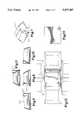
- FIGS. 27-33illustrate a fifth embodiment of the invention.
- FIG. 27is a perspective view of modified keycaps 388, 369, 370.
- One of the keycaps 388is modified to house a pointing stick, while the other key caps 369, 370 are modified so as to fit closely around the pointing stick housing without contact.
- Key cap 388includes a top surface 402 and depending side walls, e.g. side wall 404, forming a perimeter of the key cap.
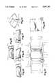
- FIG. 28is a front elevational view of the keycap combination
- FIG. 29is a rear elevational view
- FIG. 30is a side elevational view.
- FIG. 31is a top view of the keycap combination and pointing stick as implemented in a keyboard such as a computer keyboard, showing surrounding keycaps of the keyboard in dashed lines.
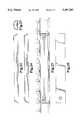
- all forces imparted to the pointing stick 386 by an operatorare transmitted to the actuator plate 246 and, through the actuator surfaces, to the force-sensing areas 248.
- the force-sensing areasare pre-loaded to a predetermined operating point, so that a lateral force applied to the button 386 results in a differential electrical signal because the force applied to some of the force-sensing elements is increased while the force applied to other force-sensing elements is decreased.
- An arrangement of three sensors as shown, or four sensors,may be used. In the latter case, a force applied in any direction off the X or Y axis results in resistance to change in all four sensing elements.
Landscapes
- Engineering & Computer Science (AREA)
- General Engineering & Computer Science (AREA)
- Theoretical Computer Science (AREA)
- Physics & Mathematics (AREA)
- General Physics & Mathematics (AREA)
- Human Computer Interaction (AREA)
- Automation & Control Theory (AREA)
- Position Input By Displaying (AREA)
Abstract
Description
Claims (11)
Priority Applications (4)
| Application Number | Priority Date | Filing Date | Title |
|---|---|---|---|
| US08/275,946US5407285A (en) | 1990-07-24 | 1994-07-14 | Pointing stick in a computer keyboard for cursor control |
| JP6214251AJPH0822376A (en) | 1994-02-16 | 1994-08-15 | Composite key for computer keyboard provided with pointing stick for cursor control |
| US08/410,348US5568987A (en) | 1990-07-24 | 1995-03-24 | Pointing stick in a computer keyboard for cursor control |
| US08/480,163US5701142A (en) | 1990-07-24 | 1995-06-07 | Pointing stick with tripod actuator for cursor control in a computer keyboard |
Applications Claiming Priority (6)
| Application Number | Priority Date | Filing Date | Title |
|---|---|---|---|
| US07/557,546US5231386A (en) | 1990-07-24 | 1990-07-24 | Keyswitch-integrated pointing assembly |
| US08/011,676US5339129A (en) | 1992-02-14 | 1993-02-01 | Device for wiping liquids off running webs of photographic material |
| US9648593A | 1993-07-22 | 1993-07-22 | |
| US08/104,777US5541622A (en) | 1990-07-24 | 1993-08-16 | Miniature isometric joystick |
| US1884294A | 1994-02-16 | 1994-02-16 | |
| US08/275,946US5407285A (en) | 1990-07-24 | 1994-07-14 | Pointing stick in a computer keyboard for cursor control |
Related Parent Applications (3)
| Application Number | Title | Priority Date | Filing Date |
|---|---|---|---|
| US29011676Continuation-In-Part | 1993-08-09 | ||
| US08/104,777Continuation-In-PartUS5541622A (en) | 1990-07-24 | 1993-08-16 | Miniature isometric joystick |
| US29018842Continuation-In-Part | 1994-02-16 |
Related Child Applications (2)
| Application Number | Title | Priority Date | Filing Date |
|---|---|---|---|
| US08/410,348ContinuationUS5568987A (en) | 1990-07-24 | 1995-03-24 | Pointing stick in a computer keyboard for cursor control |
| US08/410,348DivisionUS5568987A (en) | 1990-07-24 | 1995-03-24 | Pointing stick in a computer keyboard for cursor control |
Publications (1)
| Publication Number | Publication Date |
|---|---|
| US5407285Atrue US5407285A (en) | 1995-04-18 |
Family
ID=27533451
Family Applications (2)
| Application Number | Title | Priority Date | Filing Date |
|---|---|---|---|
| US08/275,946Expired - LifetimeUS5407285A (en) | 1990-07-24 | 1994-07-14 | Pointing stick in a computer keyboard for cursor control |
| US08/410,348Expired - LifetimeUS5568987A (en) | 1990-07-24 | 1995-03-24 | Pointing stick in a computer keyboard for cursor control |
Family Applications After (1)
| Application Number | Title | Priority Date | Filing Date |
|---|---|---|---|
| US08/410,348Expired - LifetimeUS5568987A (en) | 1990-07-24 | 1995-03-24 | Pointing stick in a computer keyboard for cursor control |
Country Status (1)
| Country | Link |
|---|---|
| US (2) | US5407285A (en) |
Cited By (29)
| Publication number | Priority date | Publication date | Assignee | Title |
|---|---|---|---|---|
| US5701142A (en)* | 1990-07-24 | 1997-12-23 | In-Control Solutions, Inc. | Pointing stick with tripod actuator for cursor control in a computer keyboard |
| EP0844584A2 (en) | 1996-11-25 | 1998-05-27 | CTS Corporation | Pointing device |
| US5760764A (en)* | 1995-12-13 | 1998-06-02 | Altra | Computer display cursor controller with serial interface |
| US5771037A (en)* | 1995-07-24 | 1998-06-23 | Altra | Computer display cursor controller |
| US5798754A (en)* | 1994-09-30 | 1998-08-25 | International Business Machines Corporation | Grip cap for computer control stick |
| EP0862103A2 (en) | 1997-02-04 | 1998-09-02 | CTS Corporation | Pointing device |
| US5805139A (en)* | 1994-01-31 | 1998-09-08 | Kabushiki Kaisha Toshiba | Computer system with standard built-in pointing device, which is connectable to optional external pointing device |
| US5894301A (en)* | 1996-09-23 | 1999-04-13 | Cts Corporation | Collar mounted pointing stick |
| EP0992872A2 (en) | 1998-10-07 | 2000-04-12 | CTS Corporation | Pointing device and method of making pointing device |
| US6121954A (en)* | 1997-09-26 | 2000-09-19 | Cts Corporation | Unified bodied z-axis sensing pointing stick |
| GB2347895A (en)* | 2000-07-03 | 2000-09-20 | Eric Douglas Rayner | Keyboard with an integral mouse/pointer incorporated into a space bar thereof |
| US6128671A (en)* | 1998-05-18 | 2000-10-03 | F.J. Tieman B.V. | Tactile feel device having a plurality of pins that allow a user to read information from the pins and make selection by depressing the pins |
| US6137475A (en)* | 1998-05-21 | 2000-10-24 | Cts Corporation | Pointing stick having an interposer connecting layer |
| US6184865B1 (en) | 1996-10-23 | 2001-02-06 | International Business Machines Corporation | Capacitive pointing stick apparatus for symbol manipulation in a graphical user interface |
| WO2001014957A1 (en)* | 1999-08-26 | 2001-03-01 | Hiew Pang Leow | Control stick for a finger pointing device |
| US6239786B1 (en)* | 1998-11-30 | 2001-05-29 | Cts Corporation | Pointing stick with top mounted z-axis sensor |
| US6331849B1 (en) | 1999-02-25 | 2001-12-18 | Cts Corporation | Integrated surface-mount pointing device |
| US6433777B1 (en) | 1999-09-29 | 2002-08-13 | Gateway, Inc. | Apparatus for extending a cursor control stick |
| US6621485B1 (en) | 1996-09-26 | 2003-09-16 | Giv, Llc | Gel cushion for keyboard cursor control stick |
| US6724369B2 (en) | 1996-09-26 | 2004-04-20 | Giv, Llc | Textured cushion for keyboard cursor control stick |
| US20050253810A1 (en)* | 1996-09-26 | 2005-11-17 | Slotta Mark R | Textured cushion for cursor control stick |
| US6970159B2 (en) | 2001-06-25 | 2005-11-29 | Gray Robin S | Mouse printing device with integrated touch pad buttons |
| US20070063974A1 (en)* | 1996-09-26 | 2007-03-22 | Slotta Mark R | Textured cushion for cursor control stick |
| US20100124634A1 (en)* | 1996-09-26 | 2010-05-20 | Slotta Mark R | Cushioned cap with annular portion and method for forming same |
| US20140225830A1 (en)* | 2013-02-12 | 2014-08-14 | Lenovo (Singapore) Pte, Ltd. | Pointing device, keyboard assemblyand portable computer |
| US20150194279A1 (en)* | 2014-01-09 | 2015-07-09 | Playrapid | Command button for a game pad and game pad equipped with such a button |
| US20160059122A1 (en)* | 2014-08-28 | 2016-03-03 | Nintendo Co., Ltd. | Information processing terminal and game device |
| US20210116961A1 (en)* | 2003-08-18 | 2021-04-22 | Apple Inc. | Actuating user interface for media player |
| US11079859B2 (en)* | 2019-01-15 | 2021-08-03 | Lenovo (Singapore) Pte Ltd | Electronic apparatus having a point stick in a keyboard |
Families Citing this family (15)
| Publication number | Priority date | Publication date | Assignee | Title |
|---|---|---|---|---|
| US5889508A (en)* | 1996-09-26 | 1999-03-30 | Slotta; Mark R. | Cushion for keyboard cursor control stick |
| US5870082A (en)* | 1996-10-31 | 1999-02-09 | International Business Machines Corporation | Pointing device with reciprocating grip cap |
| US6135958A (en)* | 1998-08-06 | 2000-10-24 | Acuson Corporation | Ultrasound imaging system with touch-pad pointing device |
| US6384861B1 (en) | 1998-12-22 | 2002-05-07 | Gateway, Inc | Image capture device having cursor generating and control apparatus |
| US6295050B1 (en) | 1999-03-18 | 2001-09-25 | International Business Machines Corporation | Joy stick pointing device to control the movement of a graphical element on a computer display monitor |
| US6469694B1 (en) | 1999-04-13 | 2002-10-22 | Peter J. Mikan | Mouse emulation keyboard system |
| KR20010025777A (en)* | 1999-09-01 | 2001-04-06 | 이형도 | Method of processing multi-key in key inputting device |
| US6520699B2 (en)* | 2001-02-16 | 2003-02-18 | Toshiyasu Abe | Keyboard |
| JP4048435B2 (en)* | 2003-10-23 | 2008-02-20 | ソニー株式会社 | Electronics |
| US7764275B2 (en)* | 2007-01-04 | 2010-07-27 | International Business Machines Corporation | Touch sensor track point and methods |
| US20090027339A1 (en)* | 2007-07-26 | 2009-01-29 | Doczy Paul J | Computing device pointing stick assembly |
| JP5161338B2 (en)* | 2011-05-09 | 2013-03-13 | 株式会社ソニー・コンピュータエンタテインメント | keyboard |
| CN102945085A (en)* | 2012-11-20 | 2013-02-27 | 余炎良 | Design and input method of multifunctional keyboard and multifunctional keyboard |
| US9645655B2 (en) | 2013-03-29 | 2017-05-09 | International Business Machines Corporation | Integrated touchpad and keyboard |
| CN103413714B (en)* | 2013-07-30 | 2016-05-11 | 苏州达方电子有限公司 | Vernier control button and illuminated keyboard thereof |
Citations (5)
| Publication number | Priority date | Publication date | Assignee | Title |
|---|---|---|---|---|
| US3523184A (en)* | 1967-12-07 | 1970-08-04 | Diehl | Operational keyboard system |
| US4680577A (en)* | 1983-11-28 | 1987-07-14 | Tektronix, Inc. | Multipurpose cursor control keyswitch |
| US4947461A (en)* | 1989-03-03 | 1990-08-07 | Murakami Kaimeido Co. Ltd. | Multi-position electrical switch |
| US5012230A (en)* | 1987-04-07 | 1991-04-30 | Sony Corporation | Input device for digital processor based apparatus |
| US5204511A (en)* | 1988-11-11 | 1993-04-20 | Siemans Nixdorf Informationssysteme AG | Alphanumeric keyboard |
Family Cites Families (4)
| Publication number | Priority date | Publication date | Assignee | Title |
|---|---|---|---|---|
| JPS5168726A (en)* | 1974-12-12 | 1976-06-14 | Hosiden Electronics Co | |
| US4313113A (en)* | 1980-03-24 | 1982-01-26 | Xerox Corporation | Cursor control |
| US4394548A (en)* | 1982-03-08 | 1983-07-19 | Amp Incorporated | Joystick switch |
| WO1992009996A1 (en)* | 1990-11-29 | 1992-06-11 | Lexmark International, Inc. | Analog input device located in the primary typing area of a keyboard |
- 1994
- 1994-07-14USUS08/275,946patent/US5407285A/ennot_activeExpired - Lifetime
- 1995
- 1995-03-24USUS08/410,348patent/US5568987A/ennot_activeExpired - Lifetime
Patent Citations (5)
| Publication number | Priority date | Publication date | Assignee | Title |
|---|---|---|---|---|
| US3523184A (en)* | 1967-12-07 | 1970-08-04 | Diehl | Operational keyboard system |
| US4680577A (en)* | 1983-11-28 | 1987-07-14 | Tektronix, Inc. | Multipurpose cursor control keyswitch |
| US5012230A (en)* | 1987-04-07 | 1991-04-30 | Sony Corporation | Input device for digital processor based apparatus |
| US5204511A (en)* | 1988-11-11 | 1993-04-20 | Siemans Nixdorf Informationssysteme AG | Alphanumeric keyboard |
| US4947461A (en)* | 1989-03-03 | 1990-08-07 | Murakami Kaimeido Co. Ltd. | Multi-position electrical switch |
Non-Patent Citations (6)
| Title |
|---|
| "Cover Story: Green Machine," PC Magazine, May 25, 1993, p. 135. |
| Bennett et al. "Digital Joystick Switch" IBM Technical Disclosure Bulletin, vol. 21, No. 12, May 1979. |
| Bennett et al. Digital Joystick Switch IBM Technical Disclosure Bulletin, vol. 21, No. 12, May 1979.* |
| Cover Story: Green Machine, PC Magazine, May 25, 1993, p. 135.* |
| Toshiba s Sale Flyer Port g Models T3400CT & T3400.* |
| Toshiba's Sale Flyer "Portege" Models T3400CT & T3400. |
Cited By (37)
| Publication number | Priority date | Publication date | Assignee | Title |
|---|---|---|---|---|
| US5701142A (en)* | 1990-07-24 | 1997-12-23 | In-Control Solutions, Inc. | Pointing stick with tripod actuator for cursor control in a computer keyboard |
| US5805139A (en)* | 1994-01-31 | 1998-09-08 | Kabushiki Kaisha Toshiba | Computer system with standard built-in pointing device, which is connectable to optional external pointing device |
| US5798754A (en)* | 1994-09-30 | 1998-08-25 | International Business Machines Corporation | Grip cap for computer control stick |
| US5771037A (en)* | 1995-07-24 | 1998-06-23 | Altra | Computer display cursor controller |
| US5760764A (en)* | 1995-12-13 | 1998-06-02 | Altra | Computer display cursor controller with serial interface |
| US5894301A (en)* | 1996-09-23 | 1999-04-13 | Cts Corporation | Collar mounted pointing stick |
| US20050253810A1 (en)* | 1996-09-26 | 2005-11-17 | Slotta Mark R | Textured cushion for cursor control stick |
| US8120579B2 (en) | 1996-09-26 | 2012-02-21 | Giv, Llc | Textured cushion for cursor control stick |
| US20100124634A1 (en)* | 1996-09-26 | 2010-05-20 | Slotta Mark R | Cushioned cap with annular portion and method for forming same |
| US20070063974A1 (en)* | 1996-09-26 | 2007-03-22 | Slotta Mark R | Textured cushion for cursor control stick |
| US6621485B1 (en) | 1996-09-26 | 2003-09-16 | Giv, Llc | Gel cushion for keyboard cursor control stick |
| US20040239623A1 (en)* | 1996-09-26 | 2004-12-02 | Slotta Mark R. | Textured cushion for keyboard cursor control stick |
| US6724369B2 (en) | 1996-09-26 | 2004-04-20 | Giv, Llc | Textured cushion for keyboard cursor control stick |
| US6184865B1 (en) | 1996-10-23 | 2001-02-06 | International Business Machines Corporation | Capacitive pointing stick apparatus for symbol manipulation in a graphical user interface |
| US5966117A (en)* | 1996-11-25 | 1999-10-12 | Cts Corporation | Z-axis sensing pointing stick with base as strain concentrator |
| EP0844584A2 (en) | 1996-11-25 | 1998-05-27 | CTS Corporation | Pointing device |
| US6002388A (en)* | 1997-02-04 | 1999-12-14 | Cts Corporation | Pointing stick having a flexible interposer |
| EP0862103A2 (en) | 1997-02-04 | 1998-09-02 | CTS Corporation | Pointing device |
| US6121954A (en)* | 1997-09-26 | 2000-09-19 | Cts Corporation | Unified bodied z-axis sensing pointing stick |
| US6128671A (en)* | 1998-05-18 | 2000-10-03 | F.J. Tieman B.V. | Tactile feel device having a plurality of pins that allow a user to read information from the pins and make selection by depressing the pins |
| US6137475A (en)* | 1998-05-21 | 2000-10-24 | Cts Corporation | Pointing stick having an interposer connecting layer |
| US6359613B1 (en) | 1998-10-07 | 2002-03-19 | Cts Corporation | Pointing stick having chip resistors |
| EP0992872A2 (en) | 1998-10-07 | 2000-04-12 | CTS Corporation | Pointing device and method of making pointing device |
| US6239786B1 (en)* | 1998-11-30 | 2001-05-29 | Cts Corporation | Pointing stick with top mounted z-axis sensor |
| US6331849B1 (en) | 1999-02-25 | 2001-12-18 | Cts Corporation | Integrated surface-mount pointing device |
| WO2001014957A1 (en)* | 1999-08-26 | 2001-03-01 | Hiew Pang Leow | Control stick for a finger pointing device |
| US6433777B1 (en) | 1999-09-29 | 2002-08-13 | Gateway, Inc. | Apparatus for extending a cursor control stick |
| GB2347895B (en)* | 2000-07-03 | 2001-02-14 | Eric Douglas Rayner | Ergonomic fully integrated computer keyboard and pointing device |
| GB2347895A (en)* | 2000-07-03 | 2000-09-20 | Eric Douglas Rayner | Keyboard with an integral mouse/pointer incorporated into a space bar thereof |
| US6970159B2 (en) | 2001-06-25 | 2005-11-29 | Gray Robin S | Mouse printing device with integrated touch pad buttons |
| US20210116961A1 (en)* | 2003-08-18 | 2021-04-22 | Apple Inc. | Actuating user interface for media player |
| US20140225830A1 (en)* | 2013-02-12 | 2014-08-14 | Lenovo (Singapore) Pte, Ltd. | Pointing device, keyboard assemblyand portable computer |
| US9465449B2 (en)* | 2013-02-12 | 2016-10-11 | Lenovo (Singapore) Pte. Ltd. | Sensor configuration of a pointing device of a keyboard |
| US20150194279A1 (en)* | 2014-01-09 | 2015-07-09 | Playrapid | Command button for a game pad and game pad equipped with such a button |
| US20160059122A1 (en)* | 2014-08-28 | 2016-03-03 | Nintendo Co., Ltd. | Information processing terminal and game device |
| US9975042B2 (en)* | 2014-08-28 | 2018-05-22 | Nintendo Co., Ltd. | Information processing terminal and game device |
| US11079859B2 (en)* | 2019-01-15 | 2021-08-03 | Lenovo (Singapore) Pte Ltd | Electronic apparatus having a point stick in a keyboard |
Also Published As
| Publication number | Publication date |
|---|---|
| US5568987A (en) | 1996-10-29 |
Similar Documents
| Publication | Publication Date | Title |
|---|---|---|
| US5407285A (en) | Pointing stick in a computer keyboard for cursor control | |
| US5889507A (en) | Miniature isometric joystick | |
| US5499041A (en) | Keyboard integrated pointing device | |
| US5521596A (en) | Analog input device located in the primary typing area of a keyboard | |
| US5701142A (en) | Pointing stick with tripod actuator for cursor control in a computer keyboard | |
| EP0864958B1 (en) | Pointing device for information processing apparatus | |
| US6239786B1 (en) | Pointing stick with top mounted z-axis sensor | |
| US5966117A (en) | Z-axis sensing pointing stick with base as strain concentrator | |
| US20020018048A1 (en) | Z-axis pointing stick with esd protection | |
| US10928911B2 (en) | Movement capability for buttonless touchpads and forcepads | |
| JP4933263B2 (en) | Modular assembly for self-searching computer pointing device | |
| JP2000047811A (en) | Input device | |
| US6417838B1 (en) | Electronic equipment having input device that permits operations, including positional control in moving cursor and scrolling of document on screen | |
| US5883617A (en) | Pointing device with improved cursor control data | |
| US5455556A (en) | Single station cursor device suitable for keyboards | |
| US8471811B2 (en) | Puck-based pointing device that provides multiple buttons | |
| US6295050B1 (en) | Joy stick pointing device to control the movement of a graphical element on a computer display monitor | |
| US20020054015A1 (en) | Control device | |
| WO1992009996A1 (en) | Analog input device located in the primary typing area of a keyboard | |
| US7978173B2 (en) | Pointing device including a moveable puck with mechanical detents | |
| US20030066739A1 (en) | Controller with tactile feedback | |
| WO1990007786A2 (en) | Finger mouse computer input device | |
| JP2001228967A (en) | Pointing device | |
| JPH0822376A (en) | Composite key for computer keyboard provided with pointing stick for cursor control | |
| JPH10281904A (en) | Load sensor |
Legal Events
| Date | Code | Title | Description |
|---|---|---|---|
| AS | Assignment | Owner name:HOME ROW, INC., OREGON Free format text:ASSIGNMENT OF ASSIGNORS INTEREST;ASSIGNOR:FRANZ, PATRICK J.;REEL/FRAME:007091/0667 Effective date:19940714 | |
| FEPP | Fee payment procedure | Free format text:PAYOR NUMBER ASSIGNED (ORIGINAL EVENT CODE: ASPN); ENTITY STATUS OF PATENT OWNER: LARGE ENTITY | |
| STCF | Information on status: patent grant | Free format text:PATENTED CASE | |
| AS | Assignment | Owner name:INCONTROL SOLUTIONS, INC., OREGON Free format text:ASSIGNMENT OF ASSIGNORS INTEREST;ASSIGNOR:HOME ROW, INC.;REEL/FRAME:008167/0670 Effective date:19960123 | |
| FEPP | Fee payment procedure | Free format text:PAT HLDR NO LONGER CLAIMS SMALL ENT STAT AS SMALL BUSINESS (ORIGINAL EVENT CODE: LSM2); ENTITY STATUS OF PATENT OWNER: LARGE ENTITY | |
| REFU | Refund | Free format text:REFUND - PAYMENT OF MAINTENANCE FEE, 4TH YR, SMALL ENTITY (ORIGINAL EVENT CODE: R283); ENTITY STATUS OF PATENT OWNER: LARGE ENTITY | |
| FPAY | Fee payment | Year of fee payment:4 | |
| REMI | Maintenance fee reminder mailed | ||
| FPAY | Fee payment | Year of fee payment:8 | |
| SULP | Surcharge for late payment | Year of fee payment:7 | |
| AS | Assignment | Owner name:PRIMAX ELECTRONICS, LTD., TAIWAN Free format text:TECHNOLOGY TRANSFER AGREEMENT;ASSIGNOR:INCONTROL SOLUTIONS, INC.;REEL/FRAME:016722/0688 Effective date:20030404 | |
| AS | Assignment | Owner name:TRANSPACIFIC PLASMA, LLC,TAIWAN Free format text:ASSIGNMENT OF ASSIGNORS INTEREST;ASSIGNOR:PRIMAX ELECTRONICS LTD.;REEL/FRAME:018047/0778 Effective date:20060626 Owner name:TRANSPACIFIC PLASMA, LLC, TAIWAN Free format text:ASSIGNMENT OF ASSIGNORS INTEREST;ASSIGNOR:PRIMAX ELECTRONICS LTD.;REEL/FRAME:018047/0778 Effective date:20060626 | |
| FPAY | Fee payment | Year of fee payment:12 | |
| AS | Assignment | Owner name:PRIMAX ELECTRONICS LTD.,TAIWAN Free format text:LICENSE;ASSIGNORS:TRANSPACIFIC IP LTD.;TRANSPACIFIC PLASMA LLC;REEL/FRAME:018787/0358 Effective date:20060404 Owner name:PRIMAX ELECTRONICS LTD., TAIWAN Free format text:LICENSE;ASSIGNORS:TRANSPACIFIC IP LTD.;TRANSPACIFIC PLASMA LLC;REEL/FRAME:018787/0358 Effective date:20060404 | |
| FEPP | Fee payment procedure | Free format text:PAYER NUMBER DE-ASSIGNED (ORIGINAL EVENT CODE: RMPN); ENTITY STATUS OF PATENT OWNER: LARGE ENTITY Free format text:PAYOR NUMBER ASSIGNED (ORIGINAL EVENT CODE: ASPN); ENTITY STATUS OF PATENT OWNER: LARGE ENTITY | |
| AS | Assignment | Owner name:GIZMODO LIMITED LIABILITY COMPANY, DELAWARE Free format text:MERGER;ASSIGNOR:TRANSPACIFIC PLASMA, LLC;REEL/FRAME:030628/0659 Effective date:20130213 | |
| AS | Assignment | Owner name:INTELLECTUAL VENTURES I LLC, DELAWARE Free format text:MERGER;ASSIGNOR:GIZMODO LIMITED LIABILITY COMPANY;REEL/FRAME:030639/0298 Effective date:20130214 | |
| AS | Assignment | Owner name:HANGER SOLUTIONS, LLC, GEORGIA Free format text:ASSIGNMENT OF ASSIGNORS INTEREST;ASSIGNOR:INTELLECTUAL VENTURES ASSETS 161 LLC;REEL/FRAME:052159/0509 Effective date:20191206 | |
| AS | Assignment | Owner name:INTELLECTUAL VENTURES ASSETS 161 LLC, DELAWARE Free format text:ASSIGNMENT OF ASSIGNORS INTEREST;ASSIGNOR:INTELLECTUAL VENTURES I LLC;REEL/FRAME:051945/0001 Effective date:20191126 |