US5407248A - Deformity back system - Google Patents
Deformity back systemDownload PDFInfo
- Publication number
- US5407248A US5407248AUS08/110,489US11048993AUS5407248AUS 5407248 AUS5407248 AUS 5407248AUS 11048993 AUS11048993 AUS 11048993AUS 5407248 AUS5407248 AUS 5407248A
- Authority
- US
- United States
- Prior art keywords
- front surface
- foam
- foam blocks
- pad
- back shell
- Prior art date
- Legal status (The legal status is an assumption and is not a legal conclusion. Google has not performed a legal analysis and makes no representation as to the accuracy of the status listed.)
- Expired - Fee Related
Links
Images


Classifications
- A—HUMAN NECESSITIES
- A61—MEDICAL OR VETERINARY SCIENCE; HYGIENE
- A61G—TRANSPORT, PERSONAL CONVEYANCES, OR ACCOMMODATION SPECIALLY ADAPTED FOR PATIENTS OR DISABLED PERSONS; OPERATING TABLES OR CHAIRS; CHAIRS FOR DENTISTRY; FUNERAL DEVICES
- A61G5/00—Chairs or personal conveyances specially adapted for patients or disabled persons, e.g. wheelchairs
- A61G5/10—Parts, details or accessories
- A61G5/1056—Arrangements for adjusting the seat
- A61G5/1064—Arrangements for adjusting the seat adjusting the depth of the seat
- A—HUMAN NECESSITIES
- A61—MEDICAL OR VETERINARY SCIENCE; HYGIENE
- A61G—TRANSPORT, PERSONAL CONVEYANCES, OR ACCOMMODATION SPECIALLY ADAPTED FOR PATIENTS OR DISABLED PERSONS; OPERATING TABLES OR CHAIRS; CHAIRS FOR DENTISTRY; FUNERAL DEVICES
- A61G5/00—Chairs or personal conveyances specially adapted for patients or disabled persons, e.g. wheelchairs
- A61G5/10—Parts, details or accessories
- A61G5/1054—Large wheels, e.g. higher than the seat portion
- A—HUMAN NECESSITIES
- A61—MEDICAL OR VETERINARY SCIENCE; HYGIENE
- A61G—TRANSPORT, PERSONAL CONVEYANCES, OR ACCOMMODATION SPECIALLY ADAPTED FOR PATIENTS OR DISABLED PERSONS; OPERATING TABLES OR CHAIRS; CHAIRS FOR DENTISTRY; FUNERAL DEVICES
- A61G5/00—Chairs or personal conveyances specially adapted for patients or disabled persons, e.g. wheelchairs
- A61G5/10—Parts, details or accessories
- A61G5/1056—Arrangements for adjusting the seat
- A61G5/1067—Arrangements for adjusting the seat adjusting the backrest relative to the seat portion
- A—HUMAN NECESSITIES
- A61—MEDICAL OR VETERINARY SCIENCE; HYGIENE
- A61G—TRANSPORT, PERSONAL CONVEYANCES, OR ACCOMMODATION SPECIALLY ADAPTED FOR PATIENTS OR DISABLED PERSONS; OPERATING TABLES OR CHAIRS; CHAIRS FOR DENTISTRY; FUNERAL DEVICES
- A61G5/00—Chairs or personal conveyances specially adapted for patients or disabled persons, e.g. wheelchairs
- A61G5/10—Parts, details or accessories
- A61G5/1091—Cushions, seats or abduction devices
- A—HUMAN NECESSITIES
- A61—MEDICAL OR VETERINARY SCIENCE; HYGIENE
- A61G—TRANSPORT, PERSONAL CONVEYANCES, OR ACCOMMODATION SPECIALLY ADAPTED FOR PATIENTS OR DISABLED PERSONS; OPERATING TABLES OR CHAIRS; CHAIRS FOR DENTISTRY; FUNERAL DEVICES
- A61G5/00—Chairs or personal conveyances specially adapted for patients or disabled persons, e.g. wheelchairs
- A61G5/10—Parts, details or accessories
- A61G5/12—Rests specially adapted therefor, e.g. for the head or the feet
- A—HUMAN NECESSITIES
- A61—MEDICAL OR VETERINARY SCIENCE; HYGIENE
- A61G—TRANSPORT, PERSONAL CONVEYANCES, OR ACCOMMODATION SPECIALLY ADAPTED FOR PATIENTS OR DISABLED PERSONS; OPERATING TABLES OR CHAIRS; CHAIRS FOR DENTISTRY; FUNERAL DEVICES
- A61G2210/00—Devices for specific treatment or diagnosis
- A61G2210/10—Devices for specific treatment or diagnosis for orthopedics
- Y—GENERAL TAGGING OF NEW TECHNOLOGICAL DEVELOPMENTS; GENERAL TAGGING OF CROSS-SECTIONAL TECHNOLOGIES SPANNING OVER SEVERAL SECTIONS OF THE IPC; TECHNICAL SUBJECTS COVERED BY FORMER USPC CROSS-REFERENCE ART COLLECTIONS [XRACs] AND DIGESTS
- Y10—TECHNICAL SUBJECTS COVERED BY FORMER USPC
- Y10S—TECHNICAL SUBJECTS COVERED BY FORMER USPC CROSS-REFERENCE ART COLLECTIONS [XRACs] AND DIGESTS
- Y10S297/00—Chairs and seats
- Y10S297/04—Wheelchair
- Y—GENERAL TAGGING OF NEW TECHNOLOGICAL DEVELOPMENTS; GENERAL TAGGING OF CROSS-SECTIONAL TECHNOLOGIES SPANNING OVER SEVERAL SECTIONS OF THE IPC; TECHNICAL SUBJECTS COVERED BY FORMER USPC CROSS-REFERENCE ART COLLECTIONS [XRACs] AND DIGESTS
- Y10—TECHNICAL SUBJECTS COVERED BY FORMER USPC
- Y10S—TECHNICAL SUBJECTS COVERED BY FORMER USPC CROSS-REFERENCE ART COLLECTIONS [XRACs] AND DIGESTS
- Y10S297/00—Chairs and seats
- Y10S297/06—Hook and loop type fastener
Definitions
- the present inventionrelates to a modular back system for use in wheelchairs. More particularly, the modular back system of the present invention includes a mounting means and a rigid back shell which may be fitted with a variety of padding systems.
- the mounting meansis adapted to attach the rigid back shell to the vertical posts of the wheelchair and to adjust the wheelchair rigid back at a selected position and attitude. That is, the mounting means is adapted to selectively adjust the attitude of the rigid back shell, i.e., adjust the height of the rigid back shell with respect to the seat of the wheelchair, to adjust the angle of recline of the rigid back shell and to adjust the depth of the rigid back shell (the distance forward or rearward from the vertical posts).
- the mounting meansis adapted to maintain the selected attitude adjustments of the rigid back shell when the wheelchair back system is removed from the wheelchair for transportation or storage. Thereafter, when the back is reattached to the wheelchair, the back will resume its desired, selected attitude and position and height.
- the rigid back shellis a hard, relatively rigid surface extending between the wheelchair's vertical posts to provide mechanical support to the back and extending forward, at its lateral edges with a pair of forwardly extending flanges to provide lateral support.
- the padding systemis generally mounted between the two forwardly extending flanges.
- the padding systemcomprises a contoured foam pad attached to the rigid back shell.
- a fluid pad membercomprising an envelope containing a flowable fluid material is positioned to overlie the spinal region of the user. This embodiment is particularly useful for persons which do not require extensive customization of the wheelchair back.
- the padding systemcomprises a thin shim attached to the front side of the rigid back shell.
- a plurality of thicker foam blocksare removably attached to the front side of said shim by a hook and loop fastening means.
- the blocksform a substantially continuous layer of foam of substantially uniform depth over the front of the shim.
- one or more of the foam blocksmay be removed from the shim to create a recessed area.
- the recessed areacan be used to accommodate any protrusions from the back of the user.
- a pad memberis placed over the foam blocks, including the recessed area.
- the preferred embodiment of this padcomprises an envelope containing a flowable fluid material and sized to overlie the front surface of the shim and over the front surface of the foam blocks.
- the present inventionalso contemplates the use of transition wedges which are used to provide a smooth transition from the foam blocks into the recessed areas.
- the present inventionalso contemplates the use of build-up pads or blocks which may be attached to the front side of the foam blocks and/or to the front side of the shim in the recessed area to further customize the fit of the wheelchair back for the needs of users.
- the build-up padsmay be attached to the front side of a contoured foam pad, as used in the first embodiment.
- the padding systemsincluding the contoured foam pad and blocks, transition wedges, build-up pads, fluid pad, and thin shim are all preferably covered by a fabric cover, which may be an outside cover only, or may be an outside cover enclosing an inside cover and attached to a rigid back shell by a hook and loop fastening means.
- a custom shaped backalso provides comfort and avoids skin pressure that may result in decubitus ulcers (pressure sores). Decubitus ulcers are a very serious problem that requires hospitalization, surgery, and extensive rehabilitation. It is estimated that the current cost of caring for a decubitus ulcer is in the $60,000 to $75,000 range. Naturally, while the patient is hospitalized, he is unable to travel, work, or enjoy other pleasures afforded by mobility, and tremendous and devastating psychological trauma can occur.
- the people requiring customized wheelchair backsinclude those affected with cerebral palsy, muscular dystrophy, multiple sclerosis, head injuries, and other similar ailments. Their needs for customized backs can develop because of kyphosis, scoliosis, and lordosis, plus a combination of twisted deformities in varying degrees of severity.
- the back of the wheelchairIn order to fit those people with back deformities properly in a wheelchair, the back of the wheelchair must be contoured so as to be able to fit closely to the body's shape so as to provide support over the whole back without putting too much pressure on any one point.
- the first approachis a custom foam system.
- an impressionis taken of the body. Once the impression is made, it is sent to a factory site. At the factory, foam is either carved by hand or molded to match the impression of the body shape. An upholstery cover is placed over the carved or molded foam.
- This methodsuffers from a number of disadvantages. For one, it takes a long time to construct the system (typically several weeks). It is also a labor-intensive method and, therefore, expensive. Further, when completed, the system cannot be changed even if it was done incorrectly. Systems on the average take three to six weeks to deliver and three to six weeks to remake if done improperly. The system also cannot be changed if the user's body changes over a period of time. This is especially a problem with children whose bodies quickly and continually change. It is also not possible to fit the user in his own wheelchair which increases the probability of an improper fit at the time of delivery. Rather, the fitting must be done in a fitting frame.
- the second common approachis a foam-in-place system.
- a foam-in-place systemWith this system, a flexible plastic bag is put between the user and a rigid surface. Liquid foam is then injected into the bag. The liquid foam expands into a rigid foam which takes the shape of the user's body.
- This systemalso has a number of disadvantages including the fact that it is messy, and that one cannot control the volume of the foam.
- the foam-in-place systemhas all of the above disadvantages of the custom carved molded products.
- the third systemis marketed under the trade name MATRIX. It allows custom fit to the individual by adjusting a series of metal parts that form to virtually any body contour. The hard matrix is then covered by foam and a fabric cover. This system takes an average of 4-8 hours to fit and is very difficult to refit should someone desire to change the system.
- the back system of the present inventionovercomes the foregoing problems as is more fully described below.
- the present inventionrelates to a modular wheelchair back system.
- the wheelchair system of the present inventioncomprises a rigid back shell and a mounting means adapted to removably affix the rigid back shell to the vertical posts of a wheelchair at a selected position in a selected attitude.
- the rigid back shellis fitted with one of several padding systems.
- the mounting meansis preferably a 4 point mounting means adapted to removably attach the modular back to the wheelchair in a selected position and attitude.
- the mounting meansincludes means to adjust (and maintain in the adjusted position) the back in the desired depth and angle mounted on the rigid back shell and the means to adjust and lock the height mounted on the vertical posts of the wheelchair.
- the mounting meanspreferably comprises a pair of post brackets, which are mounted on the vertical posts in a selected position, to accommodate the user's needs.
- a pair of rodsadjustably affixed to the rigid back shell, engage the vertical post brackets.
- the depth and angle of the backis controlled by adjustment of the position of the rods (which engage the post brackets) and adjustment of the position of the U bracket. Using these adjustments, the depth of the back may be adjusted forward or backwards in the chair, and the angle of the back may be adjusted.
- the selected back positionis maintained by the mounting means even after removal from the wheelchair and later replacement on the wheelchair.
- the mounting meansalso does not normally interfere with the arm rest or the folding mechanism of the chair. This allows for easy folding of the wheelchair for transportation.
- the ability to recess the backis important to lengthen or shorten seat depth for different users, to adjust backward over time to accommodate growth, and to keep feet in footrests.
- the ability to recline the rigid back shellis important to accommodate a hip angle of more than 90°, to allow users with severe kyphotic deformity to look straight ahead rather than at their lap which results in fatigue to the neck, and to increase stability by allowing the head to rest against a headrest.
- the rigid back shellincludes a monolithic, rigid surface, which is generally contoured with the vertical center line being somewhat to the rear of the lateral edges in a manner to generally conform to the shape of a human back. Attached to the lateral edges are a pair of forwardly extending flanges. The mounting means is attached to the forwardly extending flanges. While whatever type of padding system used is generally mounted within the volume defined by the forward extending flanges.
- the Padding SystemThe Padding System
- a first embodiment of the padding system of the present inventionrelates to contoured backs for wheelchairs for people who do not require extensive customization of the back. More particularly, this embodiment relates to a wheelchair back system comprising a contoured foam pad.
- a fluid pad memberis attached by a hook and loop fastening means such as is commonly available under the tradename VELCRO to overlie the front surface of the contoured foam pad along the length of the spinal region of the user and is attached to the contoured foam pad so that it runs down the middle of the contoured foam pad.
- the second embodiment of the padding system of the present inventionrelates to custom shaped backs for wheelchairs for people confined to a wheelchair and who require an extensively customized wheelchair back.
- This embodimentcomprises removable foam blocks, transition wedges and build-up pads which are attached to a thin shim.
- the foam blocksprovide a substantially continuous layer of foam having a substantially uniform depth of the entire front surface of the shell. Individual blocks can be removed in order to create a padding system surface conforming to the shape of the person's back deformity.
- the thin shimmay be placed in the rigid back shell between the rigid back shell and the foam blocks.
- build-up padscam be added to the front surface of the layer of blocks in the second embodiment or to the front surface of a contoured foam pad in the first embodiment to further customize the padding system and can be removed or added to the shim so as to create a padding system surface conforming to the shape of the person's deformed back.
- a pad memberis attached by VELCRO to the shim, the build-up pads, and the foam blocks. The pad member overlies the front surface of the shim and the foam blocks and build-up pads.
- the foam blockscan be removed from the shim to form a recessed area to provide a customized fit for the user's back with a possible depth of as much as 4 inches behind the original surface of the blocks.
- the edges of these blocksare preferably beveled so that they do not present a sharp edge to the person's body and generally do not require modification by the person setting up the system. While the preferred embodiment uses blocks which do not generally require modification by the therapist or person doing the fitting, it is understood that another embodiment could employ blocks which generally may be modified for a substantially perfect fit.
- Foam transition wedgesare provided to achieve a smooth transition from the front plane of the removable blocks to the front surface of the thin shim or rigid back shell.
- transition wedgesallow a more custom fit. Additional conformity to the user's back shape is achieved by filling in spaces or voids in areas forward of the front plane of the removable blocks or the contoured foam pad by placement of build-up pads on the front plane of the removable blocks or contoured foam pad. These build-up pads contour to the body shape in order to fill in around the body. The build-up pads can also be used in the recessed area (where the blocks were removed) to build up that area since removing the blocks may create too much of a recessed area.
- Foam lateral supports with optional reinforcing VELCRO suspendermay be attached to the front surface of the foam blocks or the contoured foam pad with VELCRO.
- the pad memberwhich overlies the foam blocks, may be a thin foam pad or a flexible envelope containing a flowable fluid material, adapted to smooth out the contour of the back over the blocks, recessed areas and add-on pads.
- a fluid pad membergenerally is used to overlie the spinal region of the user, but may be sized to overlie the entire surface of the padding system.
- a fluid pad memberis used to make the customizable padding system have a substantially perfect contoured fit to the user's back. Further, the pad member allows the person to be able to move a little while still maintaining a substantially perfect contoured fit to his body.
- the pad membercovers the whole front surface of the padding system. It is oversized by a significant amount so that it can be draped into any recesses and easily fill in over the build-ups from the build-up pads while overlying the surface of the thin shim.
- the pad memberwill also generally smooth out the edges of all the components (i.e. foam blocks, foam lateral supports, build-up pads, transition wedges) underneath it.
- the pad memberis held in its proper position by having VELCRO on the back side of the pad member, which attaches to the foam blocks, build-up pads and transition wedges and to the thin shim in the recessed area.
- the pad memberhas flaps which fold over the back of the thin shim and attach to the back of the shim by VELCRO.
- the plastic film of either side of the pad membermay be transparent so that the therapist or fitter may observe where the fluid has displaced during the fitting process, and thus adjust the fitting to provide substantially uniform pressure on contact areas of the user's back.
- a further reason for the pad member to be oversizedis to prevent hammocking.
- Hammockingis defined as a suspension of the bony prominences of the user on the surface of the padding system, thereby preventing substantial conformity of the padding system to the user's body and preventing substantially complete pressure equalization.
- the surfacewill easily yield in response to pressure from the bony prominences and therefore distribute the pressure over a larger area.
- the shim, foam blocks, build-up pads, foam lateral supports, and pad memberall fit inside the covering system which may be of two embodiments.
- One embodimentemploys an inside protective cover and an outside washable cover.
- the inside coveris incontinent and protects the whole system from any tampering with the positions of the internal components, while the outside cover may be easily removed for washing.
- the zipper of the inside covercan be partially unzipped while the user is still sitting against the system so that the therapist can make adjustments to better fit the user's body immediately. This is especially important when there have been changes in the user's body shape, and if the system is not adjusted, a substantially perfect fit will no longer exist, and a decubitus ulcer can quickly form.
- the inside coveris a full-zip enclosed cover which is attached to the pad member.
- the inside covercontains VELCRO attachment points.
- the front of the coveris oversized to avoid a hammocking effect when covering the recesses in the padding system surface.
- the covering systemmay have VELCRO points that are attached to VELCRO points on the foam blocks and the thin shim.
- the outside coveris a removable washable cover and includes extra material so that there is no hammocking effect creating pressure on the user's body. Tear out seams allow for adjustment of the cover shape depending on the deformity, to provide enhanced cosmetic appearance.
- a second embodiment of coveringis an outside stretch cover, stretching over the front of the foam parts, but leaving the back of the thin shim or contoured foam pad exposed.
- Either style of coveringis intended to provide at least one cover that will protect the internal components.
- the customizable back system of the present inventionuses removable foam blocks, transition wedges, build-up pads, and pad member, the system can be quickly set up for a user by a therapist or training fitter. Accordingly, a lot of the labor expense of producing the system that was required in the prior systems is eliminated. Further, a user can have the system the day he is fitted for it. It can even be fit into the user's own wheelchair. Even if a substantially perfect fit is not initially achieved, the components of the system can be easily changed so as to achieve a substantially perfect fit. Also it may be necessary to change the contour later if the person's body changes due to gravity, growth, etc.
- the components of the systemcan be so easily set-up, the user has an opportunity to assess and evaluate the system prior to purchasing it. Further, if some of the components of the system wear out, they can be replaced without having to have the entire system replaced. Furthermore, because a substantially perfect fit to the user's body can be achieved and because the system can allow for movement by the user, the probability of decubitus ulcers is greatly decreased over that which occurred in the prior systems. Furthermore, this system permits the concept of progressive fitting, meaning the fitter can choose to become more aggressive with successive fittings, thus allowing gradual correction of deformities or postural tendencies, much the same as when a dentist tightens teeth braces as the teeth start to straighten.
- Lateral supports attached to the rigid back shell, external to the padding systemmay be used to provide side-to-side positioning and support of the user's body. These external lateral supports may be needed instead of or in conjunction with the previously described foam lateral supports to provide more aggressive support to the user if necessary.
- External lateral supportsgenerally include a rigid bracket, foam pad, optional wedges, and optional lining fluid pad with a cover. The external lateral support fits onto the adjustable rigid back shell with VELCRO for assessment, and with bolts for permanent mounting.
- the rigid bracketfits between the side guards on the rigid back shell and the padding system, and is curved on one end to allow attachment to the rigid back shell between the rigid back shell and the thin shim.
- the external lateral supportmay be moved up and down to determine its proper position for the user before permanent mounting.
- Side-to-side positioning of the foam pad supporting the user's bodyis achieved using one or more optional wedges between the rigid bracket and the foam pad. Each wedge may be rotated to provide angular tilt adjustment of the foam pad supporting the user's body.
- An optional small lining fluid padmay be fitted onto the foam pad for additional body conformity. A cover over the foam pad, wedges, and lining fluid pad protects these components.
- the external lateral supportsprovide more aggressive lateral support than the previously described foam lateral supports attached to the padding system.
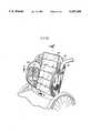
- FIG. 1shows the rigid back shell and the mounting means in a wheelchair.
- FIGS. 2 and 3show side views of the mounting means attached to the wheelchair.
- FIG. 3Ashows a side view of the mounting means using hose clamps for assessment purposes.
- FIGS. 3B and 3Cshow the operation of the twist retainers of the mounting means.
- FIG. 4shows a behind view of the mounting means attached to the wheelchair.
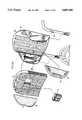
- FIG. 5Ashows a first embodiment of the padding system in place in a wheelchair.
- FIG. 5Bshows the rigid back shell, foam pad, fluid pad member, adjustable lumber support and trunk supports of the first embodiment.
- FIGS. 5C and 5Dshow cross-sectional views of padding system of the first embodiment.
- FIG. 6shows the removable foam blocks in place, the recessed area formed when the blocks are removed, and the attachment of a thin shim to the rigid back shell.
- FIG. 6Ais a view similar to FIG. 6 showing another embodiment with the thin shim removed.
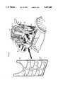
- FIG. 7shows some of the possible components of a second embodiment of the padding system.
- FIG. 8shows the pad member being placed over the padding system of the second embodiment of the padding system.
- FIG. 9shows the pad member in place.
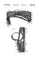
- FIGS. 10 and 11show cross-sectional views of the padding system of the second embodiment.
- FIG. 12shows a cover over the padding system of the second embodiment.
- the rigid back shell 36 and mounting means 50(consisting of post brackets 56, rods 58, screws 57, hose clamps 54, washers 77, U brackets 64, twist retainers 70, hex screws 74, bars 79, and nuts 59, 75, as shown in FIGS. 2, 3, and 4) of the modular back system of the present invention in a wheelchair are generally shown in FIG. 1.
- the modular back systemfurther comprise a padding system fitted to the rigid back shell.
- Rigid back shell 36is a hard, relatively rigid, relatively inflexible monolithic surface.
- the rigid back shell 36extends between the vertical posts 52 of the wheelchair in a generally contoured shape to provide mechanical support for the back system. Attached to the lateral edges of the rigid back shell 36 are a pair of forwardly extending flanges 38.
- the mounting means 50is attached to the forwardly extending flanges 38, while the padding system would be generally mounted within the volume defined by the forwardly extending flanges 38 (as generally shown by the arrow 35).
- the rigid back shell 36can be made of any rigid material but preferably is made of metal, particularly aluminum. It is to be understood that while the preferred invention uses a monolithic structure, the shell could be constructed of separate components bolted, or otherwise affixed together.
- each block shown in FIG. 6is preferred and that the present invention is not to be limited to the geometric configuration of each block, nor is there a requirement that each block be of the same size.
- the design of the blocksis such to allow the trained therapist to provide recesses at suitable locations customized to the shape of the user's back.
- Foam side guards 39can be placed on the interior of the forwardly extending flanges 38.
- the foam side guards 39are preferably attached by VELCRO strips 40.
- the foam side guards 39protect the user from being scratched by the mounting means 50.
- FIGS. 1-4show the preferred embodiment of the mounting means 50 used to removably affix the rigid back shell 36 to the wheelchair and, particularly to the vertical posts 52 of the wheelchair.
- FIGS. 2, 3, and 3Ashow a side view of the mounting means. This view illustrates the parts used for adjusting the height H, angle A, and depth D of the rigid back shell 36.
- the rigid back shell 36can be adjusted to any suitable height H such as from a height of 17 inches high to 22 inches high from the top of the wheelchair's horizontal rails to the top of the rigid back shell.
- the means for adjusting the heightmay be mounted on the back shell, but preferably the height adjusting means is mounted on the vertical wheelchair posts 52 as illustrated in the drawings.
- a post bracket 56is affixed to the vertical posts 52.
- the post bracket 56is preferably made of aluminum.
- Post bracket 56is adapted to engage rod 58 which is adjustably affixed to the rigid shell back 36.
- post bracket 56controls the height at which rigid shell back 36 is positioned on vertical post 52.
- Post bracket 56is initially attached to the vertical post 52 by a hose clamp 54 as shown in FIG. 3A. The bracket can be moved up or down the post 52 to adjust the height of the rigid back shell 36.
- Post bracket 56has hook means 60 in which rod 58 would rest.
- the hose clamp 54is loosened, at screw 55, so that the rigid back shell 36 can be raised or lowered to determine the proper height for the patient.
- the positionis marked with a pencil and the post bracket 56 and hose clamp 54 are removed from the vertical post 52. Two holes are drilled and tapped through the vertical post 52 of the wheelchair to mount the post brackets 56. The post bracket 56 is then placed back on the vertical post, and screws 57 are placed in each of these holes and screwed into place to hold the rigid back shell 36 steadfastly at that height.
- FIGS. 1-4also show a U bracket 64 which is adjustably affixed to the rigid back shell 36.
- the U bracketis preferably made of steel.
- the U bracket 64is adapted to curve partially around the front of vertical post 52 and is held temporarily in position by a hose clamp 66 and a hose clamp screw 68, as shown in FIG. 3A.
- a twist retainer 70is used to hold the U bracket 64 adjacent to vertical post 52, as shown in FIGS. 2 and 3.
- the temporary hose clamp 66is then removed after twist retainer 70 is so mounted.
- Twist retainer 70comprises a shoulder bolt 71, a spring 73, and a handle 75, and has a slit 72, as shown in FIG. 3B.
- FIG. 3BFIG.
- top twist retainer 70twisted 90° as it would be in the unlocked position.
- the twist retainer 70is attached to the vertical post 52 by drilling through and tapping vertical post 52 and placing the shoulder bolt through the handle 75 and through spring 73 and into the vertical post 52.
- the slit 72runs from the bottom of the twist retainer 70 to a point part way up the twist retainer 70.
- the U bracket 64will fit into the slit 72 when the top twist retainer 70 is in the down and locked position, holding the U bracket 64 in place.
- the means 50 for mounting the shell 36 to the vertical posts 52constitute four separate points: two points consisting of rods 58 resting in the post brackets 56 and the two points consisting of U brackets 64 being held in place by twist retainers 70. It is to be understood that some wheelchairs may require that the lower two mounting points be placed on the rear of the vertical posts 52.
- the rigid back shell 36can be moved forward or backwards to adjust seat depth D. This is done by changing the position of the U bracket 64 and changing the position of rod 58, i.e. loosening the top hex screw 74 on the U bracket 64 and by loosening the rod 58.
- the top hex screw 74 and the rod 58are connected by a connection means 79.
- the connection means 79is a bar 79 on the inside of the forwardly extending flanges 38 of the rigid back shell 36 as shown in FIG. 1.
- top hex screw 74is held in place by nut 75 while rod 58 is held in place by nut 59.
- the nuts 59 and 75are permanently affixed to bar 79 by welding or other suitable means.
- the rigid back shell 36is then slid forward or backwards in slot 76 and groove 78.
- the back of rigid back shell 36can be brought forward until it is substantially even with the vertical posts 52 of the wheelchair, as shown in FIG. 3 or pushed back until the front of the forwardly extending flanges 38 is substantially even with the vertical posts 52, as shown in FIG. 2.
- the groove 78can have a number of teeth in it for which the hex screw would be located in. A preferred amount of teeth would be seven, however any number can be used. Accordingly, the seat depth D can be adjusted in any of seven different increments.
- the teethcould be eliminated to provide infinite variation in seat depth D.
- the front surface of the padding systemcan be moved even further forward by placing one or more half-inch thin foam shims between the adjustable rigid back shell and the padding system.
- the rigid back shell 36can also be tilted, as shown by arrow A in FIG. 1, by sliding either the top hex screw 74 or the rod 58 farther forward (or backwards) of each other. Once the desired position is reached, top hex screw 74 and rod 58 are tightened in nuts 75 and 59, respectively, to hold that particular position steadfastly.
- One embodiment of the padding system for the modular back system of the present inventioncomprises a pre-molded foam insert for the users who do not require an extensively customized fit.
- this embodimentcould be used by a person with a spinal cord injury or a person with a recent traumatic brain injury.
- FIGS. 5A-5Dshow this embodiment.
- the pre-molded foam versioncomprises a contoured foam pad 100 which is attached to a rigid back shell 36 at the VELCRO strip(s) 103.
- Mounting meansare used to removably affix the rigid back shell 36 to the wheelchair in a selected position and attitude as previously discussed.
- the contoured foam pad 100has a symmetrical, contoured shape.
- a fluid pad member 102runs down the middle of the contoured foam pad 100 and is generally sized so that it will overlie the spinal region of the user. However, the fluid pad member 102 can be sized to lower the entire back region.
- On the back side of the fluid pad member 102are VELCRO strips which attach to VELCRO strips 101 on the contoured foam pad 100. If build-up pads 22 are used, fluid pad member 102 will overlie the front surface of the padding system, including any build-up pads 22.
- the fluid pad member 102is an envelope of plastic film that preferably is flexible at the ambient room temperatures of use, readily stretchable with fairly light pressure to avoid the hammocking problem described previously, and of a suitable thickness to avoid accidental punctures.
- the envelopecontains the flowable fluid material.
- the fluidis a highly viscous liquid, i.e., plastic or viscous thixotropic material, which flows gradually when pressure is applied to it, but which maintains its shape and position in absence of pressure.
- One such viscous fluidis commercially available under the trade name "FLOLITE", the registered mark of Alden Laboratories. Suitable flowable materials are described and claimed in the U.S. patents below, which are incorporated by reference herein:
- the bony prominences of the spinewill nestle into the pad member where needed to protect the prominences from injury caused by being in contact with the back of the wheelchair.
- Adjustable lumbar supports 104can be attached to the contoured foam pad 100 underneath the fluid pad member 102. By using a lumbar support, this embodiment can be somewhat customized to support the user. Additionally, foam lateral supports 106 can be attached to the contoured foam pad 100 at any location to further customize this embodiment. A cover can be placed over the contoured foam pad to hold the components in place as will be described later.
- FIGS. 6-12The second embodiment of the padding system used in the modular back system of the present invention is shown in FIGS. 6-12.
- a thin shim 18is affixed to a rigid back shell 36.
- the shim 18is made of foam in order to provide minimum weight, but other materials may be used.
- the shimmay be attached to the rigid back shell 36 by any means, but VELCRO 34 is generally preferred.
- a plurality of foam blocks 12are removably affixed to the shim 18, preferably by VELCRO attachment 16.
- the blocksprovide a substantially continuous layer of foam over the surface of the shim 18 and positioned forward of the front surface of the rigid back shell 36.
- the blocksare all the same depth so that the blocks provide a substantially uniform depth of foam over the front surface of the shim.
- the blocks 12may be affixed to the rigid back shell 36 also by VELCRO attachments of strips 16 as shown in FIG. 6A. Whether or not the shim 18 is used, the foam blocks 12 provide a substantially continuous layer of substantially uniform depth positioned forward of the front surface of the rigid back shell 36.
- the shim 18 and/or the rigid back shell 36be curved in the manner to provide a contouring which approximates a contour of the back of the user.
- the blocks 12when they are in place on shim 18, they provide a substantially continuous surface which is somewhat contoured to fit a human back.
- the forward facing front face of the shell 36could be any shape (such as flat) and that the contour shape required for the back of a user could be obtained by properly varying the depth of the blocks 12 so as to achieve a contour on the front surface thereof.
- FIG. 6shows the removable foam blocks 12 which are included within the second embodiment of the padding system.
- the foam blocksare preferably made of EVA, polyethylene or polyurethane, but other foam materials may be used.
- the foam blocks 12are typically 31/2" ⁇ 31/2" ⁇ 2" to 4" in depth. All of the foam blocks 12 are initially attached by VELCRO strips located on the back of the foam blocks to VELCRO strips 16 located on a thin shim 18 so as to form a substantially continuous layer of foam of substantially uniform depth over the front surface of the thin foam shim.
- the foam blocks 12can be removed individually or in groups from the thin foam shim 18 to produce a recessed area 20.
- the recessed area 20provides a customized fit to the wheelchair user's back. By recessing any protrusions from the user's back by removal of selected foam blocks, contact between the protrusion and the wheelchair back is reduced and contact between the rest of the user's back and the wheelchair back is increased.
- the foam blocks 12are all beveled so that there will be no sharp edges to cause discomfort for the user.
- transition members or wedges 26can be used, as shown in FIGS. 7 and 8.
- the transition wedges 26prevent any drastic drop offs or ledges between the recessed area 20 and the foam blocks 12.
- the wedges 26can be of any size or geometric shape. However, in a preferred embodiment, two sizes of a triangular shape are available, a full size which extends as long as the foam block and is as high as the foam block at its highest point, and a version half this size.
- the transition wedges 26have a VELCRO strip (not shown) on the back of wedge 26 that will attach to the VELCRO strip 16 located on the thin foam shim 18 or surface of the shell 36.
- FIGS. 7 and 8show build-up pads 22 of various geometric shapes and thicknesses being used to build up the area in front of the foam blocks 12.
- Build-up padsmay be used for other padding systems, wherein they are affixed to the front side of a contoured foam back pad to provide customization, as required.
- the build-up padsare made in the preferred embodiment of "display cloth" and are filled with plastic beads.
- a strip of VELCROis affixed to the back of the pad.
- the build-up padsare made of fabric, foam, and/or various other materials.
- the build-up pads 22are attached to the VELCRO strips 24 located on the front of the foam blocks 12.
- the build-up pads 22may be fabricated in various sizes and thicknesses.
- the build-up pads 22can be placed in the recessed area 20 to build that area up when the full four inches of recessed depth is not needed and are attached to strips 16.
- adjustable lateral supports 32can be utilized. These adjustable lateral supports 32 have VELCRO (not shown) on the bottom of the support which sticks to the VELCRO strips 24 on the front of the foam blocks 12.
- a VELCRO suspender 33can be used. One end of the suspender 33 is attached by VELCRO to the front of the adjustable lateral support 32 and the other end is attached to the VELCRO strip 24 on the front of the foam blocks 12. This should secure the adjustable lateral support 32, especially when the user's body weight leans against the lateral support and the suspender.
- a pad membercomprises an envelope containing a flowable fluid material.
- FIG. 9shows the pad member 28 in place. As shown in FIG. 8, the pad member 28 is attached to the thin foam shim 18, the transition wedges 26, foam lateral supports 32 and the foam blocks 12 by the use of VELCRO. Normally, it will cover the build-up pads without attaching to them.
- the pad memberis comprised of the same material as described in the first embodiment of the padding system.
- One side of the pad memberhas an opaque cover.
- the other side of the backmay be clear or transparent. This allows the therapist or trained fitter to determine if there is any bottoming out by the user. The user will lean against the deformity back system including against the pad member. After several minutes, the user will be leaned forward in the chair and the pad member will be leaned forward. If there has been a bottoming out, the opaque front cover will be able to be seen through the clear back. The therapist or fitter can then make adjustments to prevent this bottoming out.
- the pad member 28will typically have flaps 29 at the top of the pad which wrap over the top of the thin shim 18.
- the thin shim 18has VELCRO strips on its back which attach to the VELCRO strips on the flaps 29 of the pad member 28, helping to hold the pad member 28 in place.
- the pad member 28is positioned over the front surface of the foam blocks 12 and covers the whole final shape of the user's back. It is oversized by a significant amount so that it can be draped or received into the recesses 20 in the foam block layer 12 and removably attached by the VELCRO strips 16 to the shim 18 in the embodiment of FIG. 6 or to the rigid back shell 36 in the embodiment of FIG. 6A. It also can easily fill in over the build-ups from the build-up pads while overlying the surface of the thin shim. The pad member will also smooth out the edges of all the components (i.e. foam blocks, foam lateral supports, build-up pads, transition wedges) underneath it.
- FIGS. 10 and 11show a cross-sectional view of the second embodiment of the padding system of the modular back system.
- the second embodiment shown in FIG. 10comprises the thin shim 18, the foam blocks 12, the transition wedges 26, the pad member 28, the adjustable lateral support 32, the VELCRO suspender 33, a cover 30 and the rigid back shell 36.
- FIG. 11shows the second embodiment with the addition of the build-up pads 22.
- the thin shim 18has VELCRO strips 16.
- the foam blocks 12have a VELCRO strip 14 on the back of each block which attaches to the VELCRO strips 16 on the thin shim 18.
- the foam blocks 12have a VELCRO strip 24 in the front of each block to which the pad member 28 is attached in FIG.
- the transition wedges 26have a VELCRO strip on the back of the wedge and a VELCRO strip 27 on the front of the transition wedge.
- the pad member 28can also be attached to the VELCRO strips 16 of the thin shim 18, which are located in the recessed area 20 and the VELCRO strips 27 on the front of the transition wedges 26. All the components are then covered by a cover 30, as shown in FIG. 12.
- covercan be used to enclose and protect the internal components.
- the coveris a breathable, air exchange cover.
- This coveris adapted to maintain the pad member in its position with respect to the thin shim and foam blocks.
- the inside of the covercan be made of a reticulated foam 21 which draws fresh air when the user moves which decreases heat and moisture build-up.
- This coveris also more comfortable than the vinyl covers presently used in wheelchair backs. Further, it is easy to wash and is a fitted cover which fits over the system.
- Another preferred coveris one employing an inside protective cover and an outside washable cover.
- the thin shim 18preferably has VELCRO strips (not shown) on the back of the shim to removably attach to the VELCRO strips 34 of the rigid back shell 36, as shown in FIG. 6.
- the shimis foam, but it may be made from any suitable material. Accordingly, the thin shim 18 and components attached to it (i.e., foam blocks, transition wedges, build-up pads, and pad member) can be easily detached from the rigid back shell and removed from the wheelchair.
- the rigid back shell 36has foam side guards 39 on each side to protect the user from being scratched or injured by the mounting means 50.
- an external lateral support 81can be used as shown in FIG. 8.
- the external lateral supportcan be used with the first embodiment of a single contour padding system or with the second embodiment of a padding system with removable blocks.
- the external lateral support 81comprises an extended lateral bracket 82 which is preferably made of metal.
- the attachment end 84 of extended lateral bracket 82is curved at a right angle so that the attachment end 84 can fit between the thin shim 18 and the rigid back shell 36.
- a VELCRO stripis located on the attachment end 84 of the extended lateral bracket 82 to be used for assessment purposes.
- the extended lateral bracket 82can be moved up or down until the proper height for the user is determined.
- the attachment end 8.4then has two holes 85 for screws in order to permanently attach the extended lateral bracket 82 to the rigid back shell 36.
- the support end 86 of extended lateral bracket 82is shaped like a paddle and has two strips 88 of VELCRO on it.
- a contoured foam pad 90can be stuck on the VELCRO strips 88 to protect the user from being injured by the metal bracket.
- the lateral wedge 92is round and has a very narrow edge on one edge which widens out to half inch or more thick wedge at the other end. The lateral wedge 92 can be rotated to provide a tilt at any selected angle.
- the lateral wedge 92has VELCRO strips on both sides that will allow the wedge 92 to be attached to the support end 86 of the bracket and to the contoured foam pad 90.
- two wedges 92can be oppositely fastened together. The two attached wedges would then be attached to the support end 86 of the bracket and the contoured foam pad 90.
- the lining fluid pad 94has three flaps that wrap around the pad and attach by VELCRO to the support end 88 of the extended lateral bracket 82.
- the lining fluid pad 94can be of special help to those users who have bony rib cages or who move around a lot.
- a covercan be placed over the lining fluid pad. The cover will enclose the whole support end 82 of the extended lateral support 81 in order to keep it all together and in place, to keep it from getting dirty, and to add to the cosmetic look of the wheelchair.
Landscapes
- Health & Medical Sciences (AREA)
- Life Sciences & Earth Sciences (AREA)
- Animal Behavior & Ethology (AREA)
- General Health & Medical Sciences (AREA)
- Public Health (AREA)
- Veterinary Medicine (AREA)
- Orthopedics, Nursing, And Contraception (AREA)
- Chair Legs, Seat Parts, And Backrests (AREA)
- Invalid Beds And Related Equipment (AREA)
Abstract
Description
Claims (45)
Priority Applications (2)
| Application Number | Priority Date | Filing Date | Title |
|---|---|---|---|
| US08/110,489US5407248A (en) | 1991-02-20 | 1993-08-23 | Deformity back system |
| US08/369,382US5593211A (en) | 1991-02-20 | 1995-01-06 | Deformity back system |
Applications Claiming Priority (3)
| Application Number | Priority Date | Filing Date | Title |
|---|---|---|---|
| US65804591A | 1991-02-20 | 1991-02-20 | |
| US96025592A | 1992-10-13 | 1992-10-13 | |
| US08/110,489US5407248A (en) | 1991-02-20 | 1993-08-23 | Deformity back system |
Related Parent Applications (1)
| Application Number | Title | Priority Date | Filing Date |
|---|---|---|---|
| US96025592AContinuation | 1991-02-20 | 1992-10-13 |
Related Child Applications (1)
| Application Number | Title | Priority Date | Filing Date |
|---|---|---|---|
| US08/369,382DivisionUS5593211A (en) | 1991-02-20 | 1995-01-06 | Deformity back system |
Publications (1)
| Publication Number | Publication Date |
|---|---|
| US5407248Atrue US5407248A (en) | 1995-04-18 |
Family
ID=24639688
Family Applications (2)
| Application Number | Title | Priority Date | Filing Date |
|---|---|---|---|
| US08/110,489Expired - Fee RelatedUS5407248A (en) | 1991-02-20 | 1993-08-23 | Deformity back system |
| US08/369,382Expired - Fee RelatedUS5593211A (en) | 1991-02-20 | 1995-01-06 | Deformity back system |
Family Applications After (1)
| Application Number | Title | Priority Date | Filing Date |
|---|---|---|---|
| US08/369,382Expired - Fee RelatedUS5593211A (en) | 1991-02-20 | 1995-01-06 | Deformity back system |
Country Status (7)
| Country | Link |
|---|---|
| US (2) | US5407248A (en) |
| EP (2) | EP0721753B1 (en) |
| CA (1) | CA2103899A1 (en) |
| DE (2) | DE69230623T2 (en) |
| DK (1) | DK0721753T3 (en) |
| ES (1) | ES2144199T3 (en) |
| WO (1) | WO1992014387A1 (en) |
Cited By (63)
| Publication number | Priority date | Publication date | Assignee | Title |
|---|---|---|---|---|
| US5564788A (en)* | 1994-05-19 | 1996-10-15 | Skil-Care Corp. | Thoracic lumbar sacral orthosis support system |
| US5669665A (en)* | 1996-06-28 | 1997-09-23 | The First Years Inc. | Car seat cushion |
| US5803544A (en)* | 1996-08-16 | 1998-09-08 | H. O. Bostrom Company, Inc. | Seat construction with removable side cushions |
| US5806929A (en)* | 1996-01-03 | 1998-09-15 | Choi; Kyung Deok | Chair for keeping a straight posture |
| US5820214A (en)* | 1996-08-29 | 1998-10-13 | Lear Corporation | Vehicle seat cushion assembly |
| US5857743A (en)* | 1997-02-10 | 1999-01-12 | Mccord Winn Textron Inc. | Power adjustable side bolster |
| US5865504A (en)* | 1994-05-19 | 1999-02-02 | Skil-Care Corp. | Reclining backrest system for a person in a wheelchair |
| EP0903140A1 (en) | 1997-09-22 | 1999-03-24 | Sunrise Medical HHG Inc. | Notched support pads for cushioning wheelchair seatback |
| USD407353S (en) | 1997-10-06 | 1999-03-30 | Roho, Inc. | Back support for a wheelchair |
| EP0904761A1 (en) | 1997-09-19 | 1999-03-31 | Sunrise Medical HHG Inc. | Wheelchair seat back pelvic support system |
| USD408767S (en) | 1997-10-06 | 1999-04-27 | Roho, Inc. | Back support for a wheelchair |
| WO1999020155A1 (en)* | 1997-10-17 | 1999-04-29 | Irwin Seating Company | Contoured plastic seat back |
| US5931539A (en)* | 1997-11-25 | 1999-08-03 | Saiz; Manuel Munoz | Device to reduce weight or load on the spinal column for seats and the like |
| USD412685S (en) | 1997-10-06 | 1999-08-10 | Roho, Inc. | Back support pad assembly for a wheelchair |
| USD413085S (en) | 1997-10-06 | 1999-08-24 | Roho, Inc. | Back support pad assembly for a wheelchair |
| USD413841S (en)* | 1997-10-06 | 1999-09-14 | Roho, Inc. | Back support pad assembly for a wheelchair |
| US5954402A (en)* | 1997-04-28 | 1999-09-21 | Crown Therapeutics, Inc. | Size-adjustable load supporting device for wheelchairs |
| US5971417A (en)* | 1996-11-12 | 1999-10-26 | Sunrise Medical Hhg Inc. | Wheelchair with pivotal back rest |
| US5984418A (en)* | 1997-04-28 | 1999-11-16 | Crown Therapeutics, Inc. | Adjustable seat for wheelchairs |
| US6000761A (en)* | 1998-09-04 | 1999-12-14 | Rocha; Karen Eileen | Infant supporting chair |
| US6076527A (en)* | 1998-01-08 | 2000-06-20 | Rottinghaus; Herman James | Adaptive patient support and restraint system |
| US6095611A (en)* | 1997-10-07 | 2000-08-01 | Roho, Inc. | Modular backrest system for a wheelchair |
| US6203106B1 (en)* | 1999-05-17 | 2001-03-20 | Activeaid, Inc. | Chair for handicapped individuals |
| US6332651B1 (en)* | 1998-08-27 | 2001-12-25 | Ikeda Bussan Co., Ltd. | Seat for vehicle |
| US6382728B1 (en) | 1999-12-15 | 2002-05-07 | Meco Corporation | Back support for folding seat |
| US6460933B1 (en)* | 2000-02-28 | 2002-10-08 | Invacare Corporation | Multiply adjustable low back support assembly for a wheelchair |
| US6474743B1 (en) | 2000-09-18 | 2002-11-05 | Crown Therapeutics, Inc. | Wheelchair back support assembly |
| WO2003034869A1 (en)* | 2001-10-19 | 2003-05-01 | Sunrise Medical Hhg Inc. | Seat back assembly |
| US20030102706A1 (en)* | 2001-10-18 | 2003-06-05 | Jamison Float | Adjustable quick release frameless back support for a wheelchair |
| US20030197407A1 (en)* | 2002-03-29 | 2003-10-23 | Sanchez Gary L. | Health chair a dynamically balanced task chair |
| US20040104610A1 (en)* | 2002-12-02 | 2004-06-03 | Jan Jaskot | Lumbar support device |
| US20040201269A1 (en)* | 2001-11-02 | 2004-10-14 | Tarantino Lawrence J. | E.V.A. furniture |
| US20050046258A1 (en)* | 2003-07-09 | 2005-03-03 | Sanchez Gary L. | Task chair |
| USD549345S1 (en)* | 2005-12-08 | 2007-08-21 | Roger Mascull | Seat and base |
| US20070236066A1 (en)* | 2002-03-29 | 2007-10-11 | Sanchez Gary L | Task chair |
| US20070236073A1 (en)* | 2006-04-07 | 2007-10-11 | L & P Property Management Company | Layered chair back and chair seat |
| US20070296178A1 (en)* | 2004-07-26 | 2007-12-27 | Michael Markwald | Wheelchair Frame |
| US20080018156A1 (en)* | 2006-07-18 | 2008-01-24 | Global Seating Systems Llc | Seat assembly with multiple independent seat belts |
| USD565187S1 (en)* | 2006-11-20 | 2008-03-25 | Roger Thomas Mascull | Seat |
| US20080079306A1 (en)* | 2006-09-29 | 2008-04-03 | Sunrise Medical Hhg Inc. | Wheelchair seat cushion |
| US7396082B2 (en) | 2002-03-29 | 2008-07-08 | Garrex Llc | Task chair |
| US20080185899A1 (en)* | 2006-08-08 | 2008-08-07 | Van Den Nieuwboer Johanna Hend | Pathology related individual modular orthopedic seating system |
| US20090098520A1 (en)* | 2007-10-13 | 2009-04-16 | Aaron Wilson | Dressage flexion and extension training device and method |
| WO2010017644A1 (en)* | 2008-08-15 | 2010-02-18 | Rogue Wheels Inc. | Modular and/or configurable wheelchair apparatus |
| US20100132120A1 (en)* | 2008-12-02 | 2010-06-03 | Sunrise Medical Hhg, Inc. | Adaptive Seat Cushion Having A Pressure-Relieving Structure |
| US20100155536A1 (en)* | 2005-03-01 | 2010-06-24 | Bungo Asami | Aircraft Seat |
| US20100276974A1 (en)* | 2007-12-31 | 2010-11-04 | Alouisius Gerardus Huttenhuis | Adjustable backrest |
| US20110221256A1 (en)* | 2010-03-12 | 2011-09-15 | Walter Albecker | Loose fill cushions having internal support member |
| US20120001464A1 (en)* | 2009-03-18 | 2012-01-05 | Hwa Cheng Teoh | Vehicle seat cover |
| US20120280546A1 (en)* | 2011-05-06 | 2012-11-08 | Lme Inc. | Configurable cushion set for a seat |
| US20120286549A1 (en)* | 2011-05-13 | 2012-11-15 | The Boppy Company, Llc | Multi-use seat liner |
| US20140031609A1 (en)* | 2012-07-24 | 2014-01-30 | Rebecca Anna BALLARD | Sensory input devices, and sensory input methods |
| US20140084661A1 (en)* | 2011-06-16 | 2014-03-27 | Toyota Jidosha Kabushiki Kaisha | Seat backboard and vehicle seat |
| US20150158593A1 (en)* | 2013-12-11 | 2015-06-11 | Airbus Operations Gmbh | Seat modification assembly and aircraft passenger seat comprising a seat modification assembly |
| US20160207432A1 (en)* | 2009-03-18 | 2016-07-21 | Hwa Cheng Teoh | Vehicle seat cover system |
| US10081285B2 (en)* | 2016-02-01 | 2018-09-25 | Toyota Boshoku Kabushiki Kaisha | Vehicle seat |
| US10266088B2 (en)* | 2017-01-31 | 2019-04-23 | Ford Global Technologies, Llc | Vehicle seating assembly having abrasion resistant bolster insert |
| US20210038418A1 (en)* | 2018-01-29 | 2021-02-11 | Jim Mylonas | Postural orthosis support apparatus for personal body armor carriers |
| US11006758B1 (en)* | 2020-01-15 | 2021-05-18 | Merits Health Products Co., Ltd. | Chairback support structure |
| US11389350B2 (en) | 2020-09-29 | 2022-07-19 | Permobil, Inc. | Adjustable back support |
| US20230092084A1 (en)* | 2020-09-10 | 2023-03-23 | Thuja Innovations Inc. | Thermal comfort wheelchair backrest |
| US20240268558A1 (en)* | 2021-06-15 | 2024-08-15 | Tarta Design S.R.L. | Padding for support devices |
| US12161601B2 (en) | 2018-02-20 | 2024-12-10 | Angel Rodriguez-Cruz | Wheeleta |
Families Citing this family (51)
| Publication number | Priority date | Publication date | Assignee | Title |
|---|---|---|---|---|
| CA2106361C (en)* | 1993-09-16 | 2000-11-28 | Nenad B. Medjedovic | Wheelchair backrest |
| US5437496A (en)* | 1993-11-17 | 1995-08-01 | Rickard; Lori | Seating system for a mobile chair |
| US5556168A (en)* | 1994-06-17 | 1996-09-17 | Jay Medical Ltd. | Wheelchair back system |
| US6015394A (en)* | 1994-06-27 | 2000-01-18 | Young; Carol L. | Tissue stimulation apparatus for wheelchairs and the like |
| CA2131736A1 (en)* | 1994-09-09 | 1996-03-10 | David Quennell | Back support |
| US5590893A (en)* | 1994-12-28 | 1997-01-07 | No Limit Designs, Inc. | Wheelchair frame assembly |
| US5997021A (en)* | 1994-12-28 | 1999-12-07 | Sunrise Medical Hhg Inc. | Adjustable seat back assembly for a wheelchair |
| US5944385A (en)* | 1996-11-12 | 1999-08-31 | Teksource, Lc | Adjustable wheelchair back seat back angle adjustment mechanism and related devices |
| US5947562A (en)* | 1997-09-19 | 1999-09-07 | Sunrise Medical Hhg Inc. | Quick release seat |
| US5904398A (en)* | 1997-10-23 | 1999-05-18 | Farricielli; Susan | Ergonomically designed seat assembly for a portable wheelchair |
| US6231067B1 (en)* | 1998-01-12 | 2001-05-15 | Fena Design, Inc. | Motorized standing wheelchair |
| US6113189A (en)* | 1998-10-01 | 2000-09-05 | Lenjoy Engineering, Inc. | Reclining seat back attachment for wheelchair |
| US6257664B1 (en) | 1998-11-16 | 2001-07-10 | Invacare Corporation | Multiple adjustable back assembly for use with wheelchair |
| US6378947B1 (en) | 1999-04-12 | 2002-04-30 | Bloorview Macmillan Centre | Seating system |
| WO2002028339A2 (en)* | 2000-10-02 | 2002-04-11 | Sunrise Medical Hhg Inc. | Seat back |
| US6575492B2 (en)* | 2001-03-26 | 2003-06-10 | Convaid Products, Inc. | Lateral torso supports for folding wheelchairs |
| US6733074B2 (en)* | 2002-06-28 | 2004-05-11 | Marken International, Inc. | Support assembly for use with a wheelchair |
| DE20212142U1 (en) | 2002-08-07 | 2003-10-23 | Brose Fahrzeugteile GmbH & Co. Kommanditgesellschaft, Coburg, 96450 Coburg | Control device of a lumbar adjustment device of a motor vehicle |
| DE10261899B4 (en)* | 2002-12-23 | 2015-11-26 | Volkswagen Ag | Method and system for massage of body parts with a lordosis |
| EP1608533B1 (en) | 2003-04-03 | 2008-09-17 | Brock M. Walker | Seat with adjustable support system |
| US20050067861A1 (en)* | 2003-09-30 | 2005-03-31 | Eli Avihod | Wheelchair with book-style folding feature |
| US20050116525A1 (en)* | 2003-12-01 | 2005-06-02 | Holcomb Malin E. | Adjustable seat back for a wheelchair |
| US6814411B1 (en)* | 2003-12-02 | 2004-11-09 | Sunpex Technology Co., Ltd. | Fixing structure of an electric wheelchair seat |
| US7185910B2 (en)* | 2003-12-03 | 2007-03-06 | Positech Innovation Inc. | Multi adjustable chair |
| US7104610B2 (en)* | 2004-10-08 | 2006-09-12 | Marken International, Inc. | Apparatus for mounting a wheelchair back |
| US20060076814A1 (en)* | 2004-10-08 | 2006-04-13 | Ivan Samila | Adjustable backrest on personal mobility aid |
| US7147282B2 (en)* | 2004-11-08 | 2006-12-12 | Kimball International, Inc. | Chair with backrest depth adjustment mechanism |
| US7188902B1 (en)* | 2005-04-12 | 2007-03-13 | Chao-Jen Chen | Backupholstery adjustment device for wheelchair |
| WO2006116834A1 (en)* | 2005-05-03 | 2006-11-09 | Positech Innovation Inc. | Multi adjustable chair |
| JP4823592B2 (en)* | 2005-07-12 | 2011-11-24 | コンビ株式会社 | Stroller cushion |
| US7980580B2 (en)* | 2005-10-14 | 2011-07-19 | Invacare Corporation | Clamping assembly |
| EP2068676A4 (en) | 2006-10-06 | 2013-05-22 | Brock M Walker | Active response seating system |
| DE202007007001U1 (en)* | 2007-05-15 | 2007-07-26 | Dräger, Detlef | Seat shell for use with e.g. wheel chair, has adjustable cushion units with pelottes and fixed in form fit manner at vertical rack section of rack by fixing unit, where pelottes exhibit slotted hole for fixing unit |
| US7891739B2 (en)* | 2007-09-18 | 2011-02-22 | The Comfort Companies, Inc. | Apparatus for mounting a wheelchair back |
| US9326608B1 (en) | 2008-01-09 | 2016-05-03 | Goldilocks Associates, LLC | Multi-configurable seating device |
| US8590977B2 (en)* | 2008-08-07 | 2013-11-26 | Roho, Inc. | Wheelchair back mounting assembly |
| US8932692B2 (en) | 2008-10-03 | 2015-01-13 | Edizone, Llc | Cushions comprising deformable members and related methods |
| GB2475498A (en)* | 2009-11-19 | 2011-05-25 | Samantha Jayne Ltd | Birthing seat with repositionable backrest |
| JP2011155520A (en)* | 2010-01-27 | 2011-08-11 | Kyocera Corp | Mobile electronic equipment |
| US8919797B2 (en)* | 2010-03-16 | 2014-12-30 | Invacare Corp. | Wheelchair seat assembly |
| US8567863B2 (en) | 2011-03-02 | 2013-10-29 | Aspen Seating, Llc | Back support, orientation mechanism and method |
| EP2564826B9 (en)* | 2011-08-29 | 2015-04-08 | Invacare International Sàrl | Backrest for wheelchair |
| WO2014038961A1 (en)* | 2012-09-04 | 2014-03-13 | Mascull, Roger Thomas And Mascull, Elizabeth Jocelyn As Trustees Of The Rt And Ej Mascull Family Trust | A cushioning system |
| US8517469B1 (en) | 2012-09-06 | 2013-08-27 | Aspen Seating, Llc | Three-axis adjustable back support assembly and method |
| AU2014334936B2 (en) | 2013-10-16 | 2019-06-27 | Roho, Inc. | Wheelchair back mounting system |
| US10194745B2 (en) | 2015-11-06 | 2019-02-05 | The Comfort Companies, Llc | Assembly for mounting and independent multi-direction adjustment of a seat back |
| US10369065B2 (en)* | 2016-03-02 | 2019-08-06 | The Comfort Companies, Llc | Back support attachment and adjustment assembly for a wheelchair |
| EP3243491B1 (en)* | 2016-05-09 | 2018-08-01 | Etac Ab | Back support cushion |
| EP3657989B1 (en) | 2017-07-28 | 2021-09-01 | Inter-Face Medical LLC | Lower back and posture support device |
| CN109008369B (en)* | 2018-09-11 | 2023-07-14 | 浙江安吉荣艺家具有限公司 | High-elasticity electronic race chair capable of being fixed in backward leaning mode |
| JP2021142221A (en)* | 2020-03-13 | 2021-09-24 | タカノ株式会社 | Support tool for body posture holding pad and chair with pad for body posture holding |
Citations (10)
| Publication number | Priority date | Publication date | Assignee | Title |
|---|---|---|---|---|
| US3424493A (en)* | 1967-05-26 | 1969-01-28 | Louis Gottfried | Baby chair with releasable side guards |
| US3452421A (en)* | 1964-03-13 | 1969-07-01 | Caterpillar Tractor Co | Friction welding of dissimilar materials |
| US3495871A (en)* | 1966-11-29 | 1970-02-17 | Recaro Ag | Adjustable seat,primarily for motor vehicles |
| US4073537A (en)* | 1976-09-23 | 1978-02-14 | Hammersburg Don D | Universal support pads for wheelchair |
| US4402548A (en)* | 1980-02-27 | 1983-09-06 | Britax-Excelsior Limited | Safety seats for vehicles |
| US4628557A (en)* | 1984-09-14 | 1986-12-16 | Lutheran Hospital Foundation, Inc. | Adjustable hospital mattress with removable inserts |
| US4647066A (en)* | 1985-09-09 | 1987-03-03 | Walton Edward J | Orthopedic chair |
| US4706313A (en)* | 1986-05-01 | 1987-11-17 | Comfortex, Inc. | Decubitus ulcer mattress |
| US4947500A (en)* | 1988-08-25 | 1990-08-14 | OBA AG and Hans Vollmin | Therapeutic mattress, in particular for preventing or curing decubitus ulcers |
| US5018790A (en)* | 1988-07-20 | 1991-05-28 | Jay Medical, Ltd. | Customized seat cushion |
Family Cites Families (21)
| Publication number | Priority date | Publication date | Assignee | Title |
|---|---|---|---|---|
| US3237319A (en)* | 1964-06-22 | 1966-03-01 | Hanson Alden Wade | Ski boots having a thixotropic material encircling the ankle portion thereof |
| US3402411A (en)* | 1966-01-12 | 1968-09-24 | Hanson Alden Wade | Process for making boots, sports equipment and hats |
| FR1571673A (en)* | 1967-06-23 | 1969-06-20 | ||
| US3635849A (en)* | 1969-09-08 | 1972-01-18 | University Patents Inc | Polyisobutylene paraffin wax and oil blends |
| US3798799A (en)* | 1972-01-07 | 1974-03-26 | Hanson Ind Inc | Ski boot and liner therefor |
| US4038762A (en)* | 1976-03-02 | 1977-08-02 | Hanson Industries Inc. | Viscous, flowable, pressure-compensating fitting materials and their use, including their use in boots |
| US4108928A (en)* | 1976-03-02 | 1978-08-22 | Hanson Industries Inc. | Method of producing a viscous flowable pressure-compensating fitting composition from hollow thermoplastic microblends with the use of high frequency heating and dispensing the composition into a sealable, flexible, protective enclosure means |
| US4144658A (en)* | 1976-09-16 | 1979-03-20 | Hanson Industries Inc. | Viscous, flowable, pressure-compensating fitting materials and their use, including their use in boots |
| US4083127A (en)* | 1977-03-17 | 1978-04-11 | Hanson Industries Incorporated | Adjustable, pressure-compensating, custom fitting pads having predetermined amount of fitting material and their use in boots |
| US4206313A (en)* | 1978-05-30 | 1980-06-03 | S. D. Meo | Pipe cleaning nozzle |
| US4229546A (en)* | 1978-07-27 | 1980-10-21 | Hanson Industries Incorporated | Viscous, flowable, pressure-compensating fitting compositions having therein both glass and resinous microbeads |
| US4243754A (en)* | 1978-09-05 | 1981-01-06 | Hanson Industries Incorporated | Viscous, flowable, pressure-compensating fitting compositions |
| US4255202A (en)* | 1979-11-07 | 1981-03-10 | Hanson Industries Inc. | Viscous, flowable, pressure-compensating fitting compositions |
| US4795214A (en)* | 1984-11-21 | 1989-01-03 | Cambridge Technologies, Inc. | Convertible wheelchair/litter |
| US4728551A (en)* | 1987-02-24 | 1988-03-01 | Jay Eric C | Flowable pressure compensating fitting materials |
| KR910004265B1 (en)* | 1987-03-26 | 1991-06-25 | 가부시기가이샤 히다찌세이사꾸쇼 | Semiconductor laser system and manufacture method and light head |
| US4981325A (en)* | 1988-08-25 | 1991-01-01 | Dennis Zacharkow | Posture support with multi-planar adjustment |
| US5102195A (en)* | 1988-09-15 | 1992-04-07 | Pin Dot Products | Seating system |
| US5035467A (en)* | 1988-09-15 | 1991-07-30 | Pin Dot Products | Seating system |
| US4898425A (en)* | 1989-06-28 | 1990-02-06 | Mundy Philip C | Seat belt kit for wheelchairs |
| US5127709A (en)* | 1991-01-18 | 1992-07-07 | Freedom Designs, Inc. | Quick release wheelchair attachment bracket |
- 1992
- 1992-02-18EPEP96200675Apatent/EP0721753B1/ennot_activeExpired - Lifetime
- 1992-02-18DEDE69230623Tpatent/DE69230623T2/ennot_activeExpired - Fee Related
- 1992-02-18DKDK96200675Tpatent/DK0721753T3/enactive
- 1992-02-18CACA002103899Apatent/CA2103899A1/ennot_activeAbandoned
- 1992-02-18WOPCT/US1992/001291patent/WO1992014387A1/enactiveIP Right Grant
- 1992-02-18ESES96200675Tpatent/ES2144199T3/ennot_activeExpired - Lifetime
- 1992-02-18EPEP92907903Apatent/EP0572558B1/ennot_activeExpired - Lifetime
- 1992-02-18DEDE69220782Tpatent/DE69220782T2/ennot_activeExpired - Fee Related
- 1993
- 1993-08-23USUS08/110,489patent/US5407248A/ennot_activeExpired - Fee Related
- 1995
- 1995-01-06USUS08/369,382patent/US5593211A/ennot_activeExpired - Fee Related
Patent Citations (10)
| Publication number | Priority date | Publication date | Assignee | Title |
|---|---|---|---|---|
| US3452421A (en)* | 1964-03-13 | 1969-07-01 | Caterpillar Tractor Co | Friction welding of dissimilar materials |
| US3495871A (en)* | 1966-11-29 | 1970-02-17 | Recaro Ag | Adjustable seat,primarily for motor vehicles |
| US3424493A (en)* | 1967-05-26 | 1969-01-28 | Louis Gottfried | Baby chair with releasable side guards |
| US4073537A (en)* | 1976-09-23 | 1978-02-14 | Hammersburg Don D | Universal support pads for wheelchair |
| US4402548A (en)* | 1980-02-27 | 1983-09-06 | Britax-Excelsior Limited | Safety seats for vehicles |
| US4628557A (en)* | 1984-09-14 | 1986-12-16 | Lutheran Hospital Foundation, Inc. | Adjustable hospital mattress with removable inserts |
| US4647066A (en)* | 1985-09-09 | 1987-03-03 | Walton Edward J | Orthopedic chair |
| US4706313A (en)* | 1986-05-01 | 1987-11-17 | Comfortex, Inc. | Decubitus ulcer mattress |
| US5018790A (en)* | 1988-07-20 | 1991-05-28 | Jay Medical, Ltd. | Customized seat cushion |
| US4947500A (en)* | 1988-08-25 | 1990-08-14 | OBA AG and Hans Vollmin | Therapeutic mattress, in particular for preventing or curing decubitus ulcers |
Cited By (91)
| Publication number | Priority date | Publication date | Assignee | Title |
|---|---|---|---|---|
| US5865504A (en)* | 1994-05-19 | 1999-02-02 | Skil-Care Corp. | Reclining backrest system for a person in a wheelchair |
| US5564788A (en)* | 1994-05-19 | 1996-10-15 | Skil-Care Corp. | Thoracic lumbar sacral orthosis support system |
| US5806929A (en)* | 1996-01-03 | 1998-09-15 | Choi; Kyung Deok | Chair for keeping a straight posture |
| US5669665A (en)* | 1996-06-28 | 1997-09-23 | The First Years Inc. | Car seat cushion |
| US5803544A (en)* | 1996-08-16 | 1998-09-08 | H. O. Bostrom Company, Inc. | Seat construction with removable side cushions |
| US5820214A (en)* | 1996-08-29 | 1998-10-13 | Lear Corporation | Vehicle seat cushion assembly |
| US5971417A (en)* | 1996-11-12 | 1999-10-26 | Sunrise Medical Hhg Inc. | Wheelchair with pivotal back rest |
| US5857743A (en)* | 1997-02-10 | 1999-01-12 | Mccord Winn Textron Inc. | Power adjustable side bolster |
| US5984418A (en)* | 1997-04-28 | 1999-11-16 | Crown Therapeutics, Inc. | Adjustable seat for wheelchairs |
| US5954402A (en)* | 1997-04-28 | 1999-09-21 | Crown Therapeutics, Inc. | Size-adjustable load supporting device for wheelchairs |
| EP0904761A1 (en) | 1997-09-19 | 1999-03-31 | Sunrise Medical HHG Inc. | Wheelchair seat back pelvic support system |
| US6059370A (en)* | 1997-09-19 | 2000-05-09 | Sunrise Medical Hhg Inc. | Wheelchair seat back pelvic support system |
| US6033025A (en)* | 1997-09-22 | 2000-03-07 | Sunrise Medical Hhg Inc. | Notched support pads for cushioning wheelchair seatback |
| EP0903140A1 (en) | 1997-09-22 | 1999-03-24 | Sunrise Medical HHG Inc. | Notched support pads for cushioning wheelchair seatback |
| USD408767S (en) | 1997-10-06 | 1999-04-27 | Roho, Inc. | Back support for a wheelchair |
| USD413841S (en)* | 1997-10-06 | 1999-09-14 | Roho, Inc. | Back support pad assembly for a wheelchair |
| USD413085S (en) | 1997-10-06 | 1999-08-24 | Roho, Inc. | Back support pad assembly for a wheelchair |
| USD412685S (en) | 1997-10-06 | 1999-08-10 | Roho, Inc. | Back support pad assembly for a wheelchair |
| USD407353S (en) | 1997-10-06 | 1999-03-30 | Roho, Inc. | Back support for a wheelchair |
| US6095611A (en)* | 1997-10-07 | 2000-08-01 | Roho, Inc. | Modular backrest system for a wheelchair |
| US6033027A (en)* | 1997-10-17 | 2000-03-07 | Irwin Seating Company | Seat back with corner indentations |
| US5951110A (en)* | 1997-10-17 | 1999-09-14 | Irwin Seating Company | Contoured plastic seat back |
| US6168239B1 (en) | 1997-10-17 | 2001-01-02 | Irwin Seating Company | Seat back with shaped internal ribs |
| US6042187A (en)* | 1997-10-17 | 2000-03-28 | Irwin Seating Company | Seat back with aperture identifiers |
| WO1999020155A1 (en)* | 1997-10-17 | 1999-04-29 | Irwin Seating Company | Contoured plastic seat back |
| US5931539A (en)* | 1997-11-25 | 1999-08-03 | Saiz; Manuel Munoz | Device to reduce weight or load on the spinal column for seats and the like |
| US6076527A (en)* | 1998-01-08 | 2000-06-20 | Rottinghaus; Herman James | Adaptive patient support and restraint system |
| US6332651B1 (en)* | 1998-08-27 | 2001-12-25 | Ikeda Bussan Co., Ltd. | Seat for vehicle |
| WO2000013555A1 (en)* | 1998-09-04 | 2000-03-16 | Karen Rocha | Infant supporting chair |
| US6000761A (en)* | 1998-09-04 | 1999-12-14 | Rocha; Karen Eileen | Infant supporting chair |
| US6203106B1 (en)* | 1999-05-17 | 2001-03-20 | Activeaid, Inc. | Chair for handicapped individuals |
| US6382728B1 (en) | 1999-12-15 | 2002-05-07 | Meco Corporation | Back support for folding seat |
| US6460933B1 (en)* | 2000-02-28 | 2002-10-08 | Invacare Corporation | Multiply adjustable low back support assembly for a wheelchair |
| US20030052525A1 (en)* | 2000-02-28 | 2003-03-20 | Invacare Corporation | Multiply adjustable low back support assembly for a wheelchair |
| US6474743B1 (en) | 2000-09-18 | 2002-11-05 | Crown Therapeutics, Inc. | Wheelchair back support assembly |
| US6688693B2 (en)* | 2000-10-02 | 2004-02-10 | Sunrise Medical Hhg Inc. | Seat back assembly |
| US20030102706A1 (en)* | 2001-10-18 | 2003-06-05 | Jamison Float | Adjustable quick release frameless back support for a wheelchair |
| US6659563B2 (en)* | 2001-10-18 | 2003-12-09 | Invacare Corporation | Adjustable quick release frameless back support for a wheelchair |
| WO2003034869A1 (en)* | 2001-10-19 | 2003-05-01 | Sunrise Medical Hhg Inc. | Seat back assembly |
| US20040201269A1 (en)* | 2001-11-02 | 2004-10-14 | Tarantino Lawrence J. | E.V.A. furniture |
| US6997514B2 (en)* | 2001-11-02 | 2006-02-14 | Lawrence J Tarantino | E.V.A. furniture |
| US7040703B2 (en) | 2002-03-29 | 2006-05-09 | Garrex Llc | Health chair a dynamically balanced task chair |
| US7625046B2 (en) | 2002-03-29 | 2009-12-01 | Garrex Llc | Task chair |
| US20030197407A1 (en)* | 2002-03-29 | 2003-10-23 | Sanchez Gary L. | Health chair a dynamically balanced task chair |
| US20070236066A1 (en)* | 2002-03-29 | 2007-10-11 | Sanchez Gary L | Task chair |
| US7396082B2 (en) | 2002-03-29 | 2008-07-08 | Garrex Llc | Task chair |
| US20040104610A1 (en)* | 2002-12-02 | 2004-06-03 | Jan Jaskot | Lumbar support device |
| US7651163B2 (en)* | 2002-12-02 | 2010-01-26 | Logicback, Inc. | Lumbar support device |
| US20050046258A1 (en)* | 2003-07-09 | 2005-03-03 | Sanchez Gary L. | Task chair |
| US20070296178A1 (en)* | 2004-07-26 | 2007-12-27 | Michael Markwald | Wheelchair Frame |
| US8020936B2 (en)* | 2005-03-01 | 2011-09-20 | Koito Industries, Ltd. | Aircraft seat |
| US20100155536A1 (en)* | 2005-03-01 | 2010-06-24 | Bungo Asami | Aircraft Seat |
| USD549345S1 (en)* | 2005-12-08 | 2007-08-21 | Roger Mascull | Seat and base |
| US7530640B2 (en)* | 2006-04-07 | 2009-05-12 | L & P Property Management Company | Layered chair back and chair seat |
| WO2007117670A3 (en)* | 2006-04-07 | 2008-10-30 | L & P Property Management Co | Layered chair back and chair seat |
| US20070236073A1 (en)* | 2006-04-07 | 2007-10-11 | L & P Property Management Company | Layered chair back and chair seat |
| US20080018156A1 (en)* | 2006-07-18 | 2008-01-24 | Global Seating Systems Llc | Seat assembly with multiple independent seat belts |
| US20100026065A1 (en)* | 2006-07-18 | 2010-02-04 | Global Seating Systems Llc | Seat assembly with removable portions to accommodate occupant-worn equipment |
| US20080185899A1 (en)* | 2006-08-08 | 2008-08-07 | Van Den Nieuwboer Johanna Hend | Pathology related individual modular orthopedic seating system |
| US7918510B2 (en)* | 2006-08-08 | 2011-04-05 | Van Den Nieuwboer Johanna Hendrika | Pathology related individual modular orthopedic seating system |
| US20080079306A1 (en)* | 2006-09-29 | 2008-04-03 | Sunrise Medical Hhg Inc. | Wheelchair seat cushion |
| US7614704B2 (en) | 2006-09-29 | 2009-11-10 | Sunrise Medical Hhg Inc. | Wheelchair seat cushion |
| USD565187S1 (en)* | 2006-11-20 | 2008-03-25 | Roger Thomas Mascull | Seat |
| US20090098520A1 (en)* | 2007-10-13 | 2009-04-16 | Aaron Wilson | Dressage flexion and extension training device and method |
| US20100276974A1 (en)* | 2007-12-31 | 2010-11-04 | Alouisius Gerardus Huttenhuis | Adjustable backrest |
| US8632129B2 (en)* | 2007-12-31 | 2014-01-21 | Pr Sella B.V. | Adjustable backrest |
| WO2010017644A1 (en)* | 2008-08-15 | 2010-02-18 | Rogue Wheels Inc. | Modular and/or configurable wheelchair apparatus |
| US20100132120A1 (en)* | 2008-12-02 | 2010-06-03 | Sunrise Medical Hhg, Inc. | Adaptive Seat Cushion Having A Pressure-Relieving Structure |
| US20120001464A1 (en)* | 2009-03-18 | 2012-01-05 | Hwa Cheng Teoh | Vehicle seat cover |
| US20160207432A1 (en)* | 2009-03-18 | 2016-07-21 | Hwa Cheng Teoh | Vehicle seat cover system |
| US20110221256A1 (en)* | 2010-03-12 | 2011-09-15 | Walter Albecker | Loose fill cushions having internal support member |
| US8485603B2 (en)* | 2010-03-12 | 2013-07-16 | Walter Albecker | Loose fill cushions having internal support member |
| US8973993B2 (en)* | 2011-05-06 | 2015-03-10 | Lme Inc. | Configurable cushion set for a seat |
| US20120280546A1 (en)* | 2011-05-06 | 2012-11-08 | Lme Inc. | Configurable cushion set for a seat |
| US8485601B2 (en)* | 2011-05-13 | 2013-07-16 | The Boppy Company, Llc | Multi-use seat liner |
| US20120286549A1 (en)* | 2011-05-13 | 2012-11-15 | The Boppy Company, Llc | Multi-use seat liner |
| US20140084661A1 (en)* | 2011-06-16 | 2014-03-27 | Toyota Jidosha Kabushiki Kaisha | Seat backboard and vehicle seat |
| US8979204B2 (en)* | 2011-06-16 | 2015-03-17 | Toyota Jidosha Kabushiki Kaisha | Seat backboard and vehicle seat |
| US20140031609A1 (en)* | 2012-07-24 | 2014-01-30 | Rebecca Anna BALLARD | Sensory input devices, and sensory input methods |
| US20150158593A1 (en)* | 2013-12-11 | 2015-06-11 | Airbus Operations Gmbh | Seat modification assembly and aircraft passenger seat comprising a seat modification assembly |
| US9487298B2 (en)* | 2013-12-11 | 2016-11-08 | Airbus Operations Gmbh | Seat modification assembly and aircraft passenger seat comprising a seat modification assembly |
| US10081285B2 (en)* | 2016-02-01 | 2018-09-25 | Toyota Boshoku Kabushiki Kaisha | Vehicle seat |
| US10266088B2 (en)* | 2017-01-31 | 2019-04-23 | Ford Global Technologies, Llc | Vehicle seating assembly having abrasion resistant bolster insert |
| US20210038418A1 (en)* | 2018-01-29 | 2021-02-11 | Jim Mylonas | Postural orthosis support apparatus for personal body armor carriers |
| US12144759B2 (en)* | 2018-01-29 | 2024-11-19 | Jim Mylonas | Postural orthosis support apparatus for personal body armor carriers |
| US12161601B2 (en) | 2018-02-20 | 2024-12-10 | Angel Rodriguez-Cruz | Wheeleta |
| US11006758B1 (en)* | 2020-01-15 | 2021-05-18 | Merits Health Products Co., Ltd. | Chairback support structure |
| US20230092084A1 (en)* | 2020-09-10 | 2023-03-23 | Thuja Innovations Inc. | Thermal comfort wheelchair backrest |
| US12161591B2 (en)* | 2020-09-10 | 2024-12-10 | Thuja Innovations Inc. | Thermal comfort wheelchair backrest |
| US11389350B2 (en) | 2020-09-29 | 2022-07-19 | Permobil, Inc. | Adjustable back support |
| US20240268558A1 (en)* | 2021-06-15 | 2024-08-15 | Tarta Design S.R.L. | Padding for support devices |
Also Published As
| Publication number | Publication date |
|---|---|
| US5593211A (en) | 1997-01-14 |
| EP0572558B1 (en) | 1997-07-09 |
| DE69220782D1 (en) | 1997-08-14 |
| ES2144199T3 (en) | 2000-06-01 |
| EP0721753A3 (en) | 1997-01-15 |
| DE69220782T2 (en) | 1998-01-15 |
| EP0572558A4 (en) | 1994-09-14 |
| EP0721753A2 (en) | 1996-07-17 |
| CA2103899A1 (en) | 1992-08-21 |
| WO1992014387A1 (en) | 1992-09-03 |
| DE69230623D1 (en) | 2000-03-02 |
| DE69230623T2 (en) | 2000-06-08 |
| EP0572558A1 (en) | 1993-12-08 |
| DK0721753T3 (en) | 2000-05-22 |
| EP0721753B1 (en) | 2000-01-26 |
Similar Documents
| Publication | Publication Date | Title |
|---|---|---|
| US5407248A (en) | Deformity back system | |
| EP0369284B1 (en) | Wheelchair back system | |
| US5647637A (en) | Seating and back systems for a wheelchair | |
| US4753482A (en) | Customized modular seating system | |
| US5452940A (en) | Pressure relief back cushion | |
| EP0700653B1 (en) | Spinal support system for seating | |
| US6186594B1 (en) | Flexible contour wheelchair backrest | |
| US5758926A (en) | Adjustable seating system | |
| US5551756A (en) | Orthotic wheelchair positioning device and support system | |
| US4793652A (en) | Orthopaedic seating device | |
| US5695245A (en) | Orthotic seat | |
| US6059370A (en) | Wheelchair seat back pelvic support system | |
| US5378040A (en) | Adjustable geriatric chair | |
| US6033025A (en) | Notched support pads for cushioning wheelchair seatback | |
| CA2233928C (en) | Flexible contour wheelchair backrest | |
| CA2144630C (en) | Seating and back systems for a wheelchair | |
| GB2323275A (en) | Chair | |
| HK1012218B (en) | Seating and back systems for a wheelchair |
Legal Events
| Date | Code | Title | Description |
|---|---|---|---|
| FEPP | Fee payment procedure | Free format text:PAYOR NUMBER ASSIGNED (ORIGINAL EVENT CODE: ASPN); ENTITY STATUS OF PATENT OWNER: LARGE ENTITY | |
| AS | Assignment | Owner name:JAY MEDICAL LTD., COLORADO Free format text:CHANGE OF NAME;ASSIGNOR:JAY MEDICAL INC.;REEL/FRAME:007186/0764 Effective date:19940923 Owner name:JAY MEDICAL INC., COLORADO Free format text:ASSIGNMENT OF ASSIGNORS INTEREST;ASSIGNOR:JAY MEDICAL, LTD.;REEL/FRAME:007186/0750 Effective date:19940916 | |
| AS | Assignment | Owner name:JAY MEDICAL LTD., COLORADO Free format text:CHANGE OF NAME;ASSIGNOR:JAY MEDICAL INC.;REEL/FRAME:008239/0195 Effective date:19940923 | |
| AS | Assignment | Owner name:JAY MEDICAL INC., CALIFORNIA Free format text:ASSIGNMENT OF ASSIGNORS INTEREST;ASSIGNOR:JAY MEDICAL, LTD.;REEL/FRAME:008231/0971 Effective date:19940916 | |
| AS | Assignment | Owner name:QUICKIE DESIGNS INC., CALIFORNIA Free format text:ABSTRACT OF SETTLEMENT AGREEMENT AND RELEASE;ASSIGNORS:ALDEN LABORATORIES, INC.;FLOFIT MEDICAL, LLC;PRESSURE RELIEF TECHNOLOGIES, INC.;AND OTHERS;REEL/FRAME:008677/0016 Effective date:19961119 Owner name:ALDEN LABORATORIES, INC., COLORADO Free format text:ABSTRACT OF SETTLEMENT AGREEMENT AND RELEASE;ASSIGNORS:ALDEN LABORATORIES, INC.;FLOFIT MEDICAL, LLC;PRESSURE RELIEF TECHNOLOGIES, INC.;AND OTHERS;REEL/FRAME:008677/0016 Effective date:19961119 Owner name:HANSON, ALDEN B., COLORADO Free format text:ABSTRACT OF SETTLEMENT AGREEMENT AND RELEASE;ASSIGNORS:ALDEN LABORATORIES, INC.;FLOFIT MEDICAL, LLC;PRESSURE RELIEF TECHNOLOGIES, INC.;AND OTHERS;REEL/FRAME:008677/0016 Effective date:19961119 Owner name:RIK MEDICAL, LLC, COLORADO Free format text:ABSTRACT OF SETTLEMENT AGREEMENT AND RELEASE;ASSIGNORS:ALDEN LABORATORIES, INC.;FLOFIT MEDICAL, LLC;PRESSURE RELIEF TECHNOLOGIES, INC.;AND OTHERS;REEL/FRAME:008677/0016 Effective date:19961119 Owner name:FLOWFIT MEDICAL, LLC, COLORADO Free format text:ABSTRACT OF SETTLEMENT AGREEMENT AND RELEASE;ASSIGNORS:ALDEN LABORATORIES, INC.;FLOFIT MEDICAL, LLC;PRESSURE RELIEF TECHNOLOGIES, INC.;AND OTHERS;REEL/FRAME:008677/0016 Effective date:19961119 Owner name:SUNRISE MEDICAL INC., CALIFORNIA Free format text:ABSTRACT OF SETTLEMENT AGREEMENT AND RELEASE;ASSIGNORS:ALDEN LABORATORIES, INC.;FLOFIT MEDICAL, LLC;PRESSURE RELIEF TECHNOLOGIES, INC.;AND OTHERS;REEL/FRAME:008677/0016 Effective date:19961119 Owner name:JAY MEDICAL LTD., COLORADO Free format text:ABSTRACT OF SETTLEMENT AGREEMENT AND RELEASE;ASSIGNORS:ALDEN LABORATORIES, INC.;FLOFIT MEDICAL, LLC;PRESSURE RELIEF TECHNOLOGIES, INC.;AND OTHERS;REEL/FRAME:008677/0016 Effective date:19961119 Owner name:PRESSURE RELIEF TECHNOLOGIES, INC., COLORADO Free format text:ABSTRACT OF SETTLEMENT AGREEMENT AND RELEASE;ASSIGNORS:ALDEN LABORATORIES, INC.;FLOFIT MEDICAL, LLC;PRESSURE RELIEF TECHNOLOGIES, INC.;AND OTHERS;REEL/FRAME:008677/0016 Effective date:19961119 Owner name:JAY, ERIC C., COLORADO Free format text:ABSTRACT OF SETTLEMENT AGREEMENT AND RELEASE;ASSIGNORS:ALDEN LABORATORIES, INC.;FLOFIT MEDICAL, LLC;PRESSURE RELIEF TECHNOLOGIES, INC.;AND OTHERS;REEL/FRAME:008677/0016 Effective date:19961119 Owner name:HANSON, CHRIS A., COLORADO Free format text:ABSTRACT OF SETTLEMENT AGREEMENT AND RELEASE;ASSIGNORS:ALDEN LABORATORIES, INC.;FLOFIT MEDICAL, LLC;PRESSURE RELIEF TECHNOLOGIES, INC.;AND OTHERS;REEL/FRAME:008677/0016 Effective date:19961119 | |
| FEPP | Fee payment procedure | Free format text:PAYER NUMBER DE-ASSIGNED (ORIGINAL EVENT CODE: RMPN); ENTITY STATUS OF PATENT OWNER: LARGE ENTITY Free format text:PAYOR NUMBER ASSIGNED (ORIGINAL EVENT CODE: ASPN); ENTITY STATUS OF PATENT OWNER: LARGE ENTITY Free format text:PAT HLDR NO LONGER CLAIMS SMALL ENT STAT AS INDIV INVENTOR (ORIGINAL EVENT CODE: LSM1); ENTITY STATUS OF PATENT OWNER: LARGE ENTITY | |
| AS | Assignment | Owner name:SUNRISE MEDICAL HHG INC., COLORADO Free format text:MERGER;ASSIGNOR:JAY MEDICAL LTD.;REEL/FRAME:009103/0001 Effective date:19970627 | |
| FPAY | Fee payment | Year of fee payment:4 | |
| AS | Assignment | Owner name:BANKERS TRUST COMPANY, NEW YORK Free format text:SECURITY INTEREST;ASSIGNOR:SUNRISE MEDICAL HHG INC.;REEL/FRAME:011506/0787 Effective date:20001213 | |
| FPAY | Fee payment | Year of fee payment:8 | |
| REMI | Maintenance fee reminder mailed | ||
| FEPP | Fee payment procedure | Free format text:PAYER NUMBER DE-ASSIGNED (ORIGINAL EVENT CODE: RMPN); ENTITY STATUS OF PATENT OWNER: LARGE ENTITY Free format text:PAYOR NUMBER ASSIGNED (ORIGINAL EVENT CODE: ASPN); ENTITY STATUS OF PATENT OWNER: LARGE ENTITY | |
| AS | Assignment | Owner name:SUNRISE MEDICAL HHG INC, COLORADO Free format text:PATENT RELEASE;ASSIGNOR:DEUTSCHE BANK TRUST COMPANY AMERICAS;REEL/FRAME:014683/0526 Effective date:20040512 | |
| AS | Assignment | Owner name:DEUTSCHE BANK TRUST COMPANY AMERICAS, NEW YORK Free format text:SECURITY AGREEMENT;ASSIGNOR:SUNRISE MEDICAL HHG INC.;REEL/FRAME:015302/0454 Effective date:20040513 | |
| REMI | Maintenance fee reminder mailed | ||
| LAPS | Lapse for failure to pay maintenance fees | ||
| STCH | Information on status: patent discontinuation | Free format text:PATENT EXPIRED DUE TO NONPAYMENT OF MAINTENANCE FEES UNDER 37 CFR 1.362 | |
| FP | Lapsed due to failure to pay maintenance fee | Effective date:20070418 | |
| AS | Assignment | Owner name:SUNRISE MEDICAL HHG INC., COLORADO Free format text:RELEASE BY SECURED PARTY;ASSIGNOR:DEUTSCHE BANK TRUST COMPANY AMERICAS;REEL/FRAME:035135/0273 Effective date:20121130 |