US5407084A - Glide runner support - Google Patents
Glide runner supportDownload PDFInfo
- Publication number
- US5407084A US5407084AUS08/055,529US5552993AUS5407084AUS 5407084 AUS5407084 AUS 5407084AUS 5552993 AUS5552993 AUS 5552993AUS 5407084 AUS5407084 AUS 5407084A
- Authority
- US
- United States
- Prior art keywords
- longitudinal
- members
- glide
- support system
- support
- Prior art date
- Legal status (The legal status is an assumption and is not a legal conclusion. Google has not performed a legal analysis and makes no representation as to the accuracy of the status listed.)
- Expired - Lifetime
Links
- 238000010276constructionMethods0.000claimsdescription5
- 230000002787reinforcementEffects0.000claimsdescription4
- 230000000717retained effectEffects0.000claimsdescription3
- 230000037431insertionEffects0.000claims2
- 238000003780insertionMethods0.000claims2
- 230000000694effectsEffects0.000abstractdescription7
- 230000003993interactionEffects0.000abstract1
- 239000004033plasticSubstances0.000description6
- 238000009434installationMethods0.000description3
- 239000002184metalSubstances0.000description3
- 238000000465mouldingMethods0.000description3
- 230000001788irregularEffects0.000description2
- 238000003860storageMethods0.000description2
- 239000002023woodSubstances0.000description2
- 229910000831SteelInorganic materials0.000description1
- 230000006978adaptationEffects0.000description1
- 230000000712assemblyEffects0.000description1
- 238000000429assemblyMethods0.000description1
- 238000005452bendingMethods0.000description1
- 239000011111cardboardSubstances0.000description1
- 239000000969carrierSubstances0.000description1
- 238000005553drillingMethods0.000description1
- 239000003292glueSubstances0.000description1
- 230000009191jumpingEffects0.000description1
- 238000004519manufacturing processMethods0.000description1
- 239000000463materialSubstances0.000description1
- 238000005259measurementMethods0.000description1
- 238000000034methodMethods0.000description1
- 238000012986modificationMethods0.000description1
- 230000004048modificationEffects0.000description1
- 238000005096rolling processMethods0.000description1
- 239000010959steelSubstances0.000description1
Images


Classifications
- A—HUMAN NECESSITIES
- A47—FURNITURE; DOMESTIC ARTICLES OR APPLIANCES; COFFEE MILLS; SPICE MILLS; SUCTION CLEANERS IN GENERAL
- A47B—TABLES; DESKS; OFFICE FURNITURE; CABINETS; DRAWERS; GENERAL DETAILS OF FURNITURE
- A47B88/00—Drawers for tables, cabinets or like furniture; Guides for drawers
- A47B88/40—Sliding drawers; Slides or guides therefor
- A47B88/423—Fastening devices for slides or guides
- A47B88/43—Fastening devices for slides or guides at cabinet side
- A—HUMAN NECESSITIES
- A47—FURNITURE; DOMESTIC ARTICLES OR APPLIANCES; COFFEE MILLS; SPICE MILLS; SUCTION CLEANERS IN GENERAL
- A47B—TABLES; DESKS; OFFICE FURNITURE; CABINETS; DRAWERS; GENERAL DETAILS OF FURNITURE
- A47B88/00—Drawers for tables, cabinets or like furniture; Guides for drawers
- A47B88/40—Sliding drawers; Slides or guides therefor
- A47B2088/401—Slides or guides for wire baskets
- A—HUMAN NECESSITIES
- A47—FURNITURE; DOMESTIC ARTICLES OR APPLIANCES; COFFEE MILLS; SPICE MILLS; SUCTION CLEANERS IN GENERAL
- A47B—TABLES; DESKS; OFFICE FURNITURE; CABINETS; DRAWERS; GENERAL DETAILS OF FURNITURE
- A47B2210/00—General construction of drawers, guides and guide devices
- A47B2210/0002—Guide construction for drawers
- A47B2210/0024—Slides, guides for wire basket or drawer
- A—HUMAN NECESSITIES
- A47—FURNITURE; DOMESTIC ARTICLES OR APPLIANCES; COFFEE MILLS; SPICE MILLS; SUCTION CLEANERS IN GENERAL
- A47B—TABLES; DESKS; OFFICE FURNITURE; CABINETS; DRAWERS; GENERAL DETAILS OF FURNITURE
- A47B2210/00—General construction of drawers, guides and guide devices
- A47B2210/0002—Guide construction for drawers
- A47B2210/0051—Guide position
- A47B2210/0059—Guide located at the side of the drawer
Definitions
- U.S. Pat. No. 2,946,458shows a reciprocating tray unit in the form of a wire basket made from rods, wherein the tray or basket is mounted on loops which pass over and around the rails of base member so as to reciprocate thereon.
- U.S. Pat. No. 4,025,013shows a base support platform having an extension leg for a dish drainer.
- U.S. Pat. No. 5,367,218shows a basket frame formed of wire members adapted to rest in and slide along L-shaped tracks.
- 3,082,879shows a receptacle of wire rod construction forming a tray wherein the bottom of the receptacle has wire rod loops welded to the under side of rods.
- U.S. Pat. No. 3,114,459teaches a record holding file having an open framework formed of rods and a bottom rail supported on tracks.
- U.S. Pat. No. 4,913,298shows an extractable carriage formed of a tray mounted on supporting frames which slide on tracks.
- U.S. Pat. No. 2,971,655shows a conventional reciprocating tray formed of wire elements and adapted to slide in a guide via rollers.
- the glide runner support system of the present inventionprovides a means for reciprocal movement of a containers or other such organizers closer to the user with a minimum of effort, and to hold the organizer at a desired location without the user having to engage any type of special stop or latch means.
- the present inventioncan be utilized in existing frame support systems or with simple and inexpensive tubular frames.
- the present support glide runner systemhas interchangeable members and is readily adaptable for supporting multi-layer container units.
- the present inventionrelates to a glide runner support system having a pair of longitudinal members mounted to a vertical or horizontal frame by brackets integrally formed on the distal end of the longitudinal members.
- a wire basket, drawer, or other organizeris slidably supported within longitudinal channels formed within the longitudinal members.
- the glide runner supportsare designed so that flexing the support members extending from the container slidably supported within the channels creates a trussing effect increasing the friction to control the sliding movement and reciprocation of the container within the glide runner supports.
- a further object of the present inventionis to utilize longitudinal members for the glide runner support which are symmetrical, in order to simplify installation of the longitudinal members within a drawer or frame support by merely aligning the longitudinal members parallel to one another, and spaced the proper distance apart from one another.
- the glide runner supportcomprising a pair of longitudinal members having a longitudinal interior channel extending the length thereof, and means for attachment of the longitudinal members in spaced relationship to a support structure for supporting a container having a means for support extending therefrom, movably slidably retained in cooperative relationship within the longitudinal interior channel of the longitudinal members.
- each glide runner supportcomprises a longitudinal member of unitary construction formed being bowed slightly inward and having an irregular cross-section and distal end holding brackets "C-shaped flanges".
- the longitudinal membersare spaced apart and aligned parallel an equal distance opposite one another in a frame having tubular or square leg members.
- the generally "C-shaped” holding brackets on the distal ends of each longitudinal memberare attached to the inside of the frame legs by screws.
- a reinforcement ribextends along the top and bottom of each member, and an interior, centrally located, longitudinal channel extends the length of the member.
- the longitudinal membersmay be provided with a stop means such as a lip filling the longitudinal channel at one end of the member to limit movement of the wire basket or drawer type container within the glide runner support.
- each of the glide runner supportsare positioned facing inward, toward each other.
- the longitudinal interior channelsslidably support the outer lip of a container or the arm formed by the wire basket support rods which extend around the periphery of a wire basket.
- the container support membersare slidably held within the channels of the glide runner supports.
- the glide runner supportutilizes a novel means to control the sliding movement of the organizer support member within the longitudinal interior channels of the longitudinal member.
- a trussing effectis created when downward weight is applied to the container support members supported within the interior channels of the glide runner support.
- Application of external pressure, such as generated by the user or a heavy object held within the organizercreates a trussing effect, wherein the downward pressure on the organizer support members causes the glide runner supports to flex. Flexing of the longitudinal members of the glide runner support provides a means to control the sliding reciprocating movement of the container and hold the container within the glide runner supports.
- FIG. 1is a perspective view of the glide runner support system of the present invention showing a wire basket organizer, shown in phantom lines, slidably supported by a pair of longitudinal members mounted to the vertical support members of a frame shown in phantom lines;
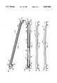
- FIG. 2is a perspective view showing a longitudinal member of the glide support runner of FIG. 1;
- FIG. 3is an inside view showing the longitudinal interior channel formed within the longitudinal member of FIG. 1;
- FIG. 4is a front end view of the longitudinal member of FIG. 1 showing the longitudinal interior channel therein;
- FIG. 5is a front end perspective view showing mounting of a bracket of the longitudinal member to a tubular frame support member shown in phantom lines.
- FIG. 6is a top or bottom view of the longitudinal member of FIG. 1;
- FIG. 7is a top view showing an inwardly bowed longitudinal member of the present invention.
- FIG. 8is a rear end perspective view showing mounting of a bracket of the longitudinal member to a tubular frame support member shown in phantom lines, and showing the stop means within the longitudinal interior channel.
- FIG. 9is a side view showing the rear end of the longitudinal member being attached to a tubular frame member by a screw extending through the bracket;
- FIG. 10is a side view showing the front end of the longitudinal member being attached to a tubular frame member by a screw extending through the bracket;
- FIG. 11is a rear end view of the longitudinal member of FIG. 1 showing the stop means within the longitudinal interior channel;
- FIG. 12is a perspective view showing an alternate embodiment of the longitudinal member shown in FIG. 1, having a centrally located stop means with the longitudinal interior channel being open at both ends; and
- FIG. 13is a side view showing a bracket having the flange oriented in horizontal alignment with the longitudinal member.
- FIG. 14is a top view showing an alternative glide runner support having a bracket flange to engage a rectangular shaped support member.
- FIG. 15is a top view showing an alternative glide runner
- the organizer 100is formed from steel wire rods crisscrossed to form a wire basket container.
- the means for support for the organizer basket 100comprises at least one projection extending from each side of the organizer 100, such as a plurality of tabs or rod members.
- the organizer 100includes a pair of horizontal side support rods defining a pair of runners 104 extending the length thereof.
- the glide runner support 10comprises a longitudinal member 12 of unitary construction having an irregular cross-section.
- the thickness of the longitudinal members 12are determined according of the size and weight of the contents for which the glide runner support 10 is designed.
- the glide runner support 10 of the present inventioncan be fabricated from wood, cardboard, plastic, metal, plastic coated metal, or any combination thereof.
- the longitudinal members 12 forming the glide runner support 10 shown in the preferred embodimentare molded from plastic.
- the glide runner support system 10 of the preferred embodimentis comprised of a pair of longitudinal members 12 removably mounted to a frame 14. As shown in the preferred embodiment, the frame 14 is shown in phantom lines having spaced apart horizontal and vertical support members 16. The longitudinal members 12 of the glider runner support 10 are spaced apart, and aligned parallel and opposite one another, and mounted to the vertical support members 16. The wire basket, drawer, or other organizer 100 is slidably supported by the longitudinal members 12.
- An interior, generally centrally located, longitudinal channel 20, or “track”extends continuously along the longitudinal member 12.
- the longitudinal interior channels 20 of each of the glide runner supports 10are positioned in alignment facing inwardly, toward each other.
- the longitudinal interior channels 20are adapted to accommodate the means for support 104 extending from the organizer 100 in cooperative relationship movably retained within the longitudinal interior channel 20 of each of the longitudinal members 12. As shown in FIG. 1, the longitudinal interior channels 20 slidably supports the runner 104 of the organizer 100 which extend around the periphery of the organizer 100.
- each channel 20is formed having a generally rectangular cross-sectional shape defining a generally flat smooth bottom channel surface 36, side channel surface 38, and top channel surface 40.
- the longitudinal member 12 of the preferred embodimentis generally straight; however, as illustrated in FIG. 7, the longitudinal members 12 of the glide runner support 10 may be formed having a slight bowed portion 22 bending inwardly toward one another for exerting frictional tension on the runners 104 of the organizer 100 slidably supported within the longitudinal interior channel 20 thereby creating a trussing effect providing the user with control and "feel", of the reciprocating movement of the container 100 movably supported therein. Moreover, the trussing effect provides a means to control the speed and extent of reciprocation of the organizer 100 within the longitudinal interior channels 20 preventing the runners 104 and organizer 100 from jumping out of the longitudinal interior channel 20.
- the glide support runners 10 of the preferred embodimentare formed from plastic and naturally have elasticity or "memory" so that the tension provided by the bow 22 is indefinite and lasts for the lifetime of the invention.
- the flexible feature of the longitudinal member 12is an important feature of the present invention not incorporated in prior art devices, for the glide runner support 10 is designed to provide limited flexible support and guide means for the runner 104 within the channel 20 during use.
- the longitudinal members 12 of the preferred embodimentinclude a stop means 34 at one end of the longitudinal interior channel 20 to limit movement of the organizer 100 within the longitudinal interior channel 20 of the glide runner support 10.
- FIGS. 2-4 and 8, 9, and 11,show the stop means 34 as a member integrally formed within the longitudinal interior channel 20 of the longitudinal member 12 to provide additional structural support to the glide runner support.
- the stop means 34may be defined by a lip, screw, or other projecting or plugging device extending into at least a portion of the longitudinal interior channel 20.
- a stop meansis not essential for use of the glide runner support system 10, for the tension created by the bow 22 enables the user to slide the organizer 100 to the desired position along the glide runner support 10.
- stop means 34may be positioned at other than one end of the longitudinal member 12.
- a glide runner support system 10 for a long cabinet sharing a dividing wallmay be comprised of longitudinal members 12 having a centrally located stop means 34, wherein organizers 100 may be inserted in both ends of the longitudinal interior channels 20 of the longitudinal members 12, such as shown in FIG. 12.
- Brackets 18for attachment of the longitudinal members 12 in spaced relationship to a support structure or frame 14 for supporting a container thereinbetween, are integrally formed on the distal ends of each longitudinal member 12.
- the brackets 18 of the preferred embodimentcomprise "C-shaped" or “semi-cylindrical shaped" flanges 26 adapted for attachment to generally round tubular members such as the vertical frame support members 16 shown in FIGS. 1, 2, 5, and 8.
- the inner surface 24 of the flanges 26is contiguous with the exterior surface of the tubular member 16. It is contemplated that the inner surface 24 of the brackets 18 may be generally rectangular shaped, such as shown by member 120 of FIG.
- flanges 26are oriented perpendicular to the longitudinal member 12 to facilitate mounting to a vertical tubular member; however, one or both of the flanges 26 of a longitudinal member 12 may be oriented in the horizontal axis for attachment to a horizontal tubular member as shown in FIG. 13.
- each longitudinal member 12The generally “C-shaped” holding brackets 18 on the distal ends of each longitudinal member 12 are mounted to the inside of the frame legs or support members 16.
- Means for securely attaching the brackets 18 to the frame support members 16 by holding members, such as screws 28, as shown in FIGS. 9 and 10,are inserted into centrally located apertures or holes 30 formed or drilled through the bracket 18, perpendicular to and through the longitudinal interior channel 20 as best shown in FIG. 3.
- the screws 28fit into a plurality of screw head sockets 32 extending horizontally through the from the longitudinal interior channel 20 toward the inner surface 24 of the flange 26.
- the sockets 32are formed "molded" into the longitudinal members 12 at the time of manufacture as shown in FIG. 2; however, the sockets 32 made be formed after the molding process by drilling.
- the sockets 32are recessed within the longitudinal interior channel 20 to provide a means for recessing the heads of the screws 28 below the surface of the longitudinal interior channel 20 to prevent interference of the screws 28 with the movement of the organizer container 100 slidably supported therein.
- Other types of holding meanssuch as clamps, velcro, or glue could also be utilized to mount the brackets 18 to a support frame 16.
- a reinforcement rib 42extends along the exterior surface of the top and bottom of the longitudinal member 12 for providing additional structural support as shown best in FIGS. 2-6. Additional structural support can be obtained by designing the longitudinal members 12 to be thicker and heavier; however, integrally molding the reinforcement rib 42 into the longitudinal member 12 prevents deformation of the plastic during the molding operation for larger, thicker glide runner supports 10, and serves to save material, reduce costs, and provides a decorative effect to enhance the appearance of the glide runner support 10.
Landscapes
- Details Of Rigid Or Semi-Rigid Containers (AREA)
Abstract
Description
Claims (19)
Priority Applications (1)
| Application Number | Priority Date | Filing Date | Title |
|---|---|---|---|
| US08/055,529US5407084A (en) | 1993-04-30 | 1993-04-30 | Glide runner support |
Applications Claiming Priority (1)
| Application Number | Priority Date | Filing Date | Title |
|---|---|---|---|
| US08/055,529US5407084A (en) | 1993-04-30 | 1993-04-30 | Glide runner support |
Publications (1)
| Publication Number | Publication Date |
|---|---|
| US5407084Atrue US5407084A (en) | 1995-04-18 |
Family
ID=21998459
Family Applications (1)
| Application Number | Title | Priority Date | Filing Date |
|---|---|---|---|
| US08/055,529Expired - LifetimeUS5407084A (en) | 1993-04-30 | 1993-04-30 | Glide runner support |
Country Status (1)
| Country | Link |
|---|---|
| US (1) | US5407084A (en) |
Cited By (51)
| Publication number | Priority date | Publication date | Assignee | Title |
|---|---|---|---|---|
| US5779069A (en)* | 1996-07-09 | 1998-07-14 | Adrian Fabricators, Inc. | Reinforced shelves |
| US5909936A (en)* | 1997-08-07 | 1999-06-08 | Clairson, Inc. | Closet drawer system |
| US6123209A (en)* | 1999-08-05 | 2000-09-26 | Tseng; Chun-Hsien | Rack |
| EP1106107A1 (en)* | 1999-12-10 | 2001-06-13 | USM Holding AG | Furniture system and drawer guide for such a system |
| US6283526B1 (en)* | 2000-09-18 | 2001-09-04 | Thomas A. Keough | Pickup truck storage system |
| USD461657S1 (en) | 2000-09-29 | 2002-08-20 | Elfa International Ab | Mounting girder for a string shelf system |
| US6467860B2 (en) | 2001-03-12 | 2002-10-22 | Clairson Corporation/Emerson Electric Company | Drawer glide system |
| USD477144S1 (en) | 2002-06-26 | 2003-07-15 | Emerson Electric Co. | Wire basket |
| US6669036B1 (en)* | 1999-10-13 | 2003-12-30 | Frank Yang | Modular storage assembly |
| USD488334S1 (en) | 2003-01-10 | 2004-04-13 | Design Ideas, Ltd. | Frame and runner elements |
| US20040104324A1 (en)* | 2002-10-07 | 2004-06-03 | Oberhaus Fred D. | Symmetrically designed snap-on shelf |
| USD516347S1 (en) | 2003-01-10 | 2006-03-07 | Design Ideas, Ltd. | Frame and runner elements |
| US20060152118A1 (en)* | 2005-01-11 | 2006-07-13 | Samsung Electronics Co., Ltd. | Refrigerator |
| US20060201899A1 (en)* | 2005-03-11 | 2006-09-14 | Ruei-Hsing Lin | Sliding rail assembly for wire basket |
| US20070235401A1 (en)* | 2006-03-29 | 2007-10-11 | Costa Charles A | Organizational basket and covering |
| USD569715S1 (en) | 2007-12-04 | 2008-05-27 | Clairson, Inc. | Track for a shelving system |
| US20080121542A1 (en)* | 2006-11-24 | 2008-05-29 | Ming-Chi Chang | Toolbox frame |
| US20080135078A1 (en)* | 2006-12-08 | 2008-06-12 | Q.S. Control Corp. | Brace for a walker |
| US20080143225A1 (en)* | 2006-12-18 | 2008-06-19 | Hirsh Industries, Inc. | Cabinet drawer and stationary drawer glide |
| USD578869S1 (en) | 2007-12-04 | 2008-10-21 | Clairson, Inc. | Mounting base |
| USD580258S1 (en) | 2007-12-04 | 2008-11-11 | Clairson, Inc. | Hang rod mounting bracket |
| USD581260S1 (en) | 2007-12-04 | 2008-11-25 | Clairson, Inc. | Bracket |
| USD585730S1 (en) | 2007-12-04 | 2009-02-03 | Clairson, Inc. | Mounting screw with self-drilling feature |
| USD587562S1 (en) | 2007-12-04 | 2009-03-03 | Clairson, Inc. | Standard |
| USD589780S1 (en) | 2007-12-04 | 2009-04-07 | Clairson, Inc. | Shelf lock |
| US20090139943A1 (en)* | 2007-12-04 | 2009-06-04 | Clairson, Inc. | Standard and track shelving systems |
| USD596931S1 (en) | 2007-12-04 | 2009-07-28 | Clairson, Inc. | Bracket |
| USD602770S1 (en) | 2007-12-04 | 2009-10-27 | Clairson, Inc. | End cap |
| USD604152S1 (en) | 2009-07-22 | 2009-11-17 | Clairson, Inc. | End bracket |
| USD604598S1 (en) | 2009-07-22 | 2009-11-24 | Clairson, Inc. | End bracket |
| USD604597S1 (en) | 2009-07-22 | 2009-11-24 | Clairson, Inc. | End bracket |
| USD606386S1 (en) | 2009-07-22 | 2009-12-22 | Clairson, Inc. | End bracket |
| USD621244S1 (en) | 2009-05-27 | 2010-08-10 | Clairson, Inc. | Hang rod mounting bracket |
| WO2010089553A1 (en)* | 2009-02-05 | 2010-08-12 | Accuride International Limited | Means for mounting an article |
| WO2010100190A1 (en)* | 2009-03-06 | 2010-09-10 | Paul Hettich Gmbh & Co. Kg | Fastening arrangement |
| WO2010100198A1 (en)* | 2009-03-06 | 2010-09-10 | Paul Hettich Gmbh & Co. Kg | Quick fastening device |
| US20110017884A1 (en)* | 2009-07-22 | 2011-01-27 | Clairson, Inc. | Shelving end brackets with interchangeable pieces for supporting hang rods of different sizes |
| USD631734S1 (en) | 2009-07-22 | 2011-02-01 | Clairson, Inc. | End bracket |
| USD668945S1 (en) | 2011-04-08 | 2012-10-16 | Clairson, Inc. | Track for a shelving system |
| US8434629B2 (en) | 2011-04-08 | 2013-05-07 | Clairson Inc. | Adjustable shelving system with overlapping tracks |
| US8646624B2 (en) | 2007-12-04 | 2014-02-11 | Clairson, Inc. | Standard and track shelving systems |
| US8726815B2 (en)* | 2002-10-01 | 2014-05-20 | Paul Giampavolo | Pallet guard |
| US20140231371A1 (en)* | 2009-02-04 | 2014-08-21 | Emd Millipore Corporation | Device For Supporting A Plurality Of Flexible Containers For Liquid |
| EP2843316A1 (en)* | 2013-08-05 | 2015-03-04 | Laag S.r.l. | Suspension device for an apparatus, in particular a baking oven |
| US20150068996A1 (en)* | 2013-09-09 | 2015-03-12 | Dongguan Master United Plastic & Hardware Products Co., Ltd | Combination drawer assembly and method of assembling the same |
| US9713379B1 (en)* | 2016-01-24 | 2017-07-25 | Frank Tsai | Shelf supporting beam configuration for shelving apparatus |
| USD837579S1 (en)* | 2017-03-15 | 2019-01-08 | Houe Aps | Slat for furniture |
| US10980344B1 (en)* | 2020-05-29 | 2021-04-20 | Matthew Comfort Co., Ltd. | Sliding rail structure for drawer of layered frame |
| US20230309693A1 (en)* | 2022-03-31 | 2023-10-05 | Lijun Li | Storage rack |
| US20250009147A1 (en)* | 2020-09-23 | 2025-01-09 | Eagle Industrial Group Inc. | Shelving unit |
| USD1081215S1 (en) | 2020-09-23 | 2025-07-01 | Kaprock Management Llc | Suspended bin rack |
Citations (22)
| Publication number | Priority date | Publication date | Assignee | Title |
|---|---|---|---|---|
| US1974983A (en)* | 1933-05-24 | 1934-09-25 | Gen Electric | Cabinet shelf |
| US2758455A (en)* | 1954-01-18 | 1956-08-14 | Amana Refrigeration Inc | Refrigerator evaporator and shelf structure |
| US2946458A (en)* | 1960-01-27 | 1960-07-26 | Shelfmaker Products Corp | Reciprocating tray units |
| US2971655A (en)* | 1960-07-08 | 1961-02-14 | Shelfmaker Products Corp | Reciprocating tray unit |
| US3175697A (en)* | 1963-11-18 | 1965-03-30 | Eldon G Kelly | Apparel rack supports |
| US3176848A (en)* | 1963-03-19 | 1965-04-06 | Russell O Stefan | Convertible record-magazine rack |
| US3655063A (en)* | 1970-08-27 | 1972-04-11 | Amp Inc | Tray and pan supporting rack |
| US3714513A (en)* | 1971-09-01 | 1973-01-30 | J Marconi | Printed circuit card retainer and rack assembly |
| US3747885A (en)* | 1970-04-21 | 1973-07-24 | Ciancimino Design Ltd | Modular joint |
| US4004819A (en)* | 1975-07-29 | 1977-01-25 | Metropolitan Wire Corporation | Mobile truck provided with improved removable racks for pans, trays and the like |
| US4253224A (en)* | 1978-12-18 | 1981-03-03 | Brazeway, Inc. | Fixtureless method of making tube joints |
| US4552415A (en)* | 1983-08-03 | 1985-11-12 | Fulterer Gesellschaft M.B.H. | Adjustable drawer mounting assembly |
| US4588096A (en)* | 1985-09-09 | 1986-05-13 | Standex International Corporation | Knock-down tray rack |
| US4795041A (en)* | 1986-11-13 | 1989-01-03 | Clairson International | Channel basket stop |
| FR2625421A3 (en)* | 1987-12-31 | 1989-07-07 | Metaltex Spa | Dismantlable shelving with removable baskets |
| US4887538A (en)* | 1988-10-12 | 1989-12-19 | Lee-Rowan Company | Modular office furniture system |
| US4904032A (en)* | 1989-01-09 | 1990-02-27 | General Electric Company | Shelf support system for a refrigerator cabinet |
| US4984694A (en)* | 1988-01-08 | 1991-01-15 | Sparring Elfa Ab | Combined string basket and string shelf system |
| US4995682A (en)* | 1988-07-28 | 1991-02-26 | Gutner Kenneth H | Storage facility for video cassettes |
| US5105953A (en)* | 1990-07-26 | 1992-04-21 | Rev-A-Shelf Inc. | Drawer storage rack |
| US5257701A (en)* | 1991-08-30 | 1993-11-02 | Nathan Edelson | Adjustable portable exercise desk |
| US5294009A (en)* | 1992-07-20 | 1994-03-15 | Maurer David A | Laundry cart apparatus |
- 1993
- 1993-04-30USUS08/055,529patent/US5407084A/ennot_activeExpired - Lifetime
Patent Citations (22)
| Publication number | Priority date | Publication date | Assignee | Title |
|---|---|---|---|---|
| US1974983A (en)* | 1933-05-24 | 1934-09-25 | Gen Electric | Cabinet shelf |
| US2758455A (en)* | 1954-01-18 | 1956-08-14 | Amana Refrigeration Inc | Refrigerator evaporator and shelf structure |
| US2946458A (en)* | 1960-01-27 | 1960-07-26 | Shelfmaker Products Corp | Reciprocating tray units |
| US2971655A (en)* | 1960-07-08 | 1961-02-14 | Shelfmaker Products Corp | Reciprocating tray unit |
| US3176848A (en)* | 1963-03-19 | 1965-04-06 | Russell O Stefan | Convertible record-magazine rack |
| US3175697A (en)* | 1963-11-18 | 1965-03-30 | Eldon G Kelly | Apparel rack supports |
| US3747885A (en)* | 1970-04-21 | 1973-07-24 | Ciancimino Design Ltd | Modular joint |
| US3655063A (en)* | 1970-08-27 | 1972-04-11 | Amp Inc | Tray and pan supporting rack |
| US3714513A (en)* | 1971-09-01 | 1973-01-30 | J Marconi | Printed circuit card retainer and rack assembly |
| US4004819A (en)* | 1975-07-29 | 1977-01-25 | Metropolitan Wire Corporation | Mobile truck provided with improved removable racks for pans, trays and the like |
| US4253224A (en)* | 1978-12-18 | 1981-03-03 | Brazeway, Inc. | Fixtureless method of making tube joints |
| US4552415A (en)* | 1983-08-03 | 1985-11-12 | Fulterer Gesellschaft M.B.H. | Adjustable drawer mounting assembly |
| US4588096A (en)* | 1985-09-09 | 1986-05-13 | Standex International Corporation | Knock-down tray rack |
| US4795041A (en)* | 1986-11-13 | 1989-01-03 | Clairson International | Channel basket stop |
| FR2625421A3 (en)* | 1987-12-31 | 1989-07-07 | Metaltex Spa | Dismantlable shelving with removable baskets |
| US4984694A (en)* | 1988-01-08 | 1991-01-15 | Sparring Elfa Ab | Combined string basket and string shelf system |
| US4995682A (en)* | 1988-07-28 | 1991-02-26 | Gutner Kenneth H | Storage facility for video cassettes |
| US4887538A (en)* | 1988-10-12 | 1989-12-19 | Lee-Rowan Company | Modular office furniture system |
| US4904032A (en)* | 1989-01-09 | 1990-02-27 | General Electric Company | Shelf support system for a refrigerator cabinet |
| US5105953A (en)* | 1990-07-26 | 1992-04-21 | Rev-A-Shelf Inc. | Drawer storage rack |
| US5257701A (en)* | 1991-08-30 | 1993-11-02 | Nathan Edelson | Adjustable portable exercise desk |
| US5294009A (en)* | 1992-07-20 | 1994-03-15 | Maurer David A | Laundry cart apparatus |
Cited By (66)
| Publication number | Priority date | Publication date | Assignee | Title |
|---|---|---|---|---|
| US5779069A (en)* | 1996-07-09 | 1998-07-14 | Adrian Fabricators, Inc. | Reinforced shelves |
| US5909936A (en)* | 1997-08-07 | 1999-06-08 | Clairson, Inc. | Closet drawer system |
| US6123209A (en)* | 1999-08-05 | 2000-09-26 | Tseng; Chun-Hsien | Rack |
| US6669036B1 (en)* | 1999-10-13 | 2003-12-30 | Frank Yang | Modular storage assembly |
| US20040134869A1 (en)* | 1999-10-13 | 2004-07-15 | Seville Classics, Inc. | Modular storage assembly |
| EP1106107A1 (en)* | 1999-12-10 | 2001-06-13 | USM Holding AG | Furniture system and drawer guide for such a system |
| US6283526B1 (en)* | 2000-09-18 | 2001-09-04 | Thomas A. Keough | Pickup truck storage system |
| USD461657S1 (en) | 2000-09-29 | 2002-08-20 | Elfa International Ab | Mounting girder for a string shelf system |
| US6467860B2 (en) | 2001-03-12 | 2002-10-22 | Clairson Corporation/Emerson Electric Company | Drawer glide system |
| US6626509B2 (en) | 2001-03-12 | 2003-09-30 | Emerson Electric Co. | Drawer glide system |
| USD477144S1 (en) | 2002-06-26 | 2003-07-15 | Emerson Electric Co. | Wire basket |
| US8726815B2 (en)* | 2002-10-01 | 2014-05-20 | Paul Giampavolo | Pallet guard |
| US20040104324A1 (en)* | 2002-10-07 | 2004-06-03 | Oberhaus Fred D. | Symmetrically designed snap-on shelf |
| US6913235B2 (en) | 2002-10-07 | 2005-07-05 | Industrial Wire Products, Inc. | Symmetrically designed snap-on shelf |
| USD488334S1 (en) | 2003-01-10 | 2004-04-13 | Design Ideas, Ltd. | Frame and runner elements |
| USD516347S1 (en) | 2003-01-10 | 2006-03-07 | Design Ideas, Ltd. | Frame and runner elements |
| US20060152118A1 (en)* | 2005-01-11 | 2006-07-13 | Samsung Electronics Co., Ltd. | Refrigerator |
| US20060201899A1 (en)* | 2005-03-11 | 2006-09-14 | Ruei-Hsing Lin | Sliding rail assembly for wire basket |
| US7108143B1 (en)* | 2005-03-11 | 2006-09-19 | Ruei-Hsing Lin | Sliding rail assembly for wire basket |
| US20070235401A1 (en)* | 2006-03-29 | 2007-10-11 | Costa Charles A | Organizational basket and covering |
| US20080121542A1 (en)* | 2006-11-24 | 2008-05-29 | Ming-Chi Chang | Toolbox frame |
| US20080135078A1 (en)* | 2006-12-08 | 2008-06-12 | Q.S. Control Corp. | Brace for a walker |
| US20080143225A1 (en)* | 2006-12-18 | 2008-06-19 | Hirsh Industries, Inc. | Cabinet drawer and stationary drawer glide |
| US8251466B2 (en) | 2006-12-18 | 2012-08-28 | Hirsh Industries, Inc. | Cabinet drawer and stationary drawer glide |
| US7976112B2 (en) | 2006-12-18 | 2011-07-12 | Hirsh Industries, Inc. | Cabinet drawer and stationary drawer glide |
| USD585730S1 (en) | 2007-12-04 | 2009-02-03 | Clairson, Inc. | Mounting screw with self-drilling feature |
| USD569715S1 (en) | 2007-12-04 | 2008-05-27 | Clairson, Inc. | Track for a shelving system |
| USD587562S1 (en) | 2007-12-04 | 2009-03-03 | Clairson, Inc. | Standard |
| USD589780S1 (en) | 2007-12-04 | 2009-04-07 | Clairson, Inc. | Shelf lock |
| US20090139943A1 (en)* | 2007-12-04 | 2009-06-04 | Clairson, Inc. | Standard and track shelving systems |
| USD596931S1 (en) | 2007-12-04 | 2009-07-28 | Clairson, Inc. | Bracket |
| USD602770S1 (en) | 2007-12-04 | 2009-10-27 | Clairson, Inc. | End cap |
| USD581260S1 (en) | 2007-12-04 | 2008-11-25 | Clairson, Inc. | Bracket |
| USD578869S1 (en) | 2007-12-04 | 2008-10-21 | Clairson, Inc. | Mounting base |
| US8646624B2 (en) | 2007-12-04 | 2014-02-11 | Clairson, Inc. | Standard and track shelving systems |
| USD580258S1 (en) | 2007-12-04 | 2008-11-11 | Clairson, Inc. | Hang rod mounting bracket |
| US7900783B2 (en) | 2007-12-04 | 2011-03-08 | Clairson, Inc. | Standard and track shelving systems |
| US9259085B2 (en)* | 2009-02-04 | 2016-02-16 | Emd Millipore Corporation | Device for supporting a plurality of flexible containers for liquid |
| US20140231371A1 (en)* | 2009-02-04 | 2014-08-21 | Emd Millipore Corporation | Device For Supporting A Plurality Of Flexible Containers For Liquid |
| WO2010089553A1 (en)* | 2009-02-05 | 2010-08-12 | Accuride International Limited | Means for mounting an article |
| WO2010100190A1 (en)* | 2009-03-06 | 2010-09-10 | Paul Hettich Gmbh & Co. Kg | Fastening arrangement |
| WO2010100198A1 (en)* | 2009-03-06 | 2010-09-10 | Paul Hettich Gmbh & Co. Kg | Quick fastening device |
| US8851591B2 (en) | 2009-03-06 | 2014-10-07 | Paul Hettich Gmbh & Co. Kg. | Fastening arrangement |
| US9078517B2 (en) | 2009-03-06 | 2015-07-14 | Paul Hettich Gmbh & Co. Kg | Quick fastening device |
| CN102378587A (en)* | 2009-03-06 | 2012-03-14 | 保罗海蒂诗有限及两合公司 | Quick fastening device |
| USD621244S1 (en) | 2009-05-27 | 2010-08-10 | Clairson, Inc. | Hang rod mounting bracket |
| USD604152S1 (en) | 2009-07-22 | 2009-11-17 | Clairson, Inc. | End bracket |
| USD604598S1 (en) | 2009-07-22 | 2009-11-24 | Clairson, Inc. | End bracket |
| US8641003B2 (en) | 2009-07-22 | 2014-02-04 | Clairson, Inc. | Shelving end brackets with interchangeable pieces for supporting hang rods of different sizes |
| US8132768B2 (en) | 2009-07-22 | 2012-03-13 | Clairson, Inc. | Shelving end brackets with interchangeable pieces for supporting hang rods of different sizes |
| USD631734S1 (en) | 2009-07-22 | 2011-02-01 | Clairson, Inc. | End bracket |
| US20110017884A1 (en)* | 2009-07-22 | 2011-01-27 | Clairson, Inc. | Shelving end brackets with interchangeable pieces for supporting hang rods of different sizes |
| USD606386S1 (en) | 2009-07-22 | 2009-12-22 | Clairson, Inc. | End bracket |
| USD604597S1 (en) | 2009-07-22 | 2009-11-24 | Clairson, Inc. | End bracket |
| US8434629B2 (en) | 2011-04-08 | 2013-05-07 | Clairson Inc. | Adjustable shelving system with overlapping tracks |
| USD668945S1 (en) | 2011-04-08 | 2012-10-16 | Clairson, Inc. | Track for a shelving system |
| EP2843316A1 (en)* | 2013-08-05 | 2015-03-04 | Laag S.r.l. | Suspension device for an apparatus, in particular a baking oven |
| US20150068996A1 (en)* | 2013-09-09 | 2015-03-12 | Dongguan Master United Plastic & Hardware Products Co., Ltd | Combination drawer assembly and method of assembling the same |
| US9131773B2 (en)* | 2013-09-09 | 2015-09-15 | Dongguan Master United Plastic & Hardware Products Co., Ltd. | Combination drawer assembly and method of assembling the same |
| US9713379B1 (en)* | 2016-01-24 | 2017-07-25 | Frank Tsai | Shelf supporting beam configuration for shelving apparatus |
| USD837579S1 (en)* | 2017-03-15 | 2019-01-08 | Houe Aps | Slat for furniture |
| US10980344B1 (en)* | 2020-05-29 | 2021-04-20 | Matthew Comfort Co., Ltd. | Sliding rail structure for drawer of layered frame |
| US20250009147A1 (en)* | 2020-09-23 | 2025-01-09 | Eagle Industrial Group Inc. | Shelving unit |
| USD1081215S1 (en) | 2020-09-23 | 2025-07-01 | Kaprock Management Llc | Suspended bin rack |
| US12364345B2 (en)* | 2020-09-23 | 2025-07-22 | Kaprock Management Llc | Shelving unit |
| US20230309693A1 (en)* | 2022-03-31 | 2023-10-05 | Lijun Li | Storage rack |
Similar Documents
| Publication | Publication Date | Title |
|---|---|---|
| US5407084A (en) | Glide runner support | |
| US5330063A (en) | Organizer glide system | |
| US6467860B2 (en) | Drawer glide system | |
| US7992728B2 (en) | Versatile track for storage and organization | |
| US4176890A (en) | Drawer and support system | |
| US6497185B1 (en) | Slidable unit for modular shelving system | |
| CN106031563B (en) | Cabinet | |
| US4288137A (en) | Drawer slide system | |
| JP2006231047A (en) | Guide rail assembly for drawer | |
| US6824231B2 (en) | Storage cabinet | |
| CA2017890A1 (en) | A pull-out guide assembly for drawers or the like | |
| US6511140B2 (en) | Pull-out device for a tall cupboard drawer | |
| US5083848A (en) | Pull-out tray for in-cabinet installation | |
| US3980365A (en) | Drawer rail system | |
| KR200433472Y1 (en) | Pull out hanger | |
| CA1037908A (en) | Cabinet sliding cantilever shelf | |
| US5131733A (en) | Mounting bracket for drawer guides | |
| US5658059A (en) | Support rail to be mounted on a side of a cabinet of an article of furniture | |
| GB2313039A (en) | Shelf for a refrigerator | |
| US5722749A (en) | Self-positioning cabinet rail for a drawer guide | |
| CN113133593A (en) | Cupboard drawer for cupboard elements | |
| JP3728037B2 (en) | Slide bookshelf | |
| CN220587787U (en) | Storage cabinet with drawable layer rack | |
| GB2342567A (en) | Liner for storage furniture | |
| US5269418A (en) | Bar for storage rack system |
Legal Events
| Date | Code | Title | Description |
|---|---|---|---|
| AS | Assignment | Owner name:VERMONT AMERICAN CORPORATION, KENTUCKY Free format text:ASSIGNMENT OF ASSIGNORS INTEREST;ASSIGNOR:REMMERS, LEE E.;REEL/FRAME:006574/0230 Effective date:19930426 | |
| STPP | Information on status: patent application and granting procedure in general | Free format text:APPLICATION UNDERGOING PREEXAM PROCESSING | |
| AS | Assignment | Owner name:CLAIRSON INTERNATIONAL CORPORATION, FLORIDA Free format text:ASSIGNMENT OF ASSIGNORS INTEREST;ASSIGNOR:VERMONT AMERICAN CORPORATION;REEL/FRAME:007271/0015 Effective date:19941220 | |
| AS | Assignment | Owner name:CLAIRSON, INC., DELAWARE Free format text:ASSIGNMENT OF ASSIGNORS INTEREST;ASSIGNOR:CLAIRSON INTERNATIONAL CORPORATION;REEL/FRAME:007786/0872 Effective date:19950228 | |
| CC | Certificate of correction | ||
| FEPP | Fee payment procedure | Free format text:PAYOR NUMBER ASSIGNED (ORIGINAL EVENT CODE: ASPN); ENTITY STATUS OF PATENT OWNER: LARGE ENTITY | |
| FPAY | Fee payment | Year of fee payment:4 | |
| FEPP | Fee payment procedure | Free format text:PAYOR NUMBER ASSIGNED (ORIGINAL EVENT CODE: ASPN); ENTITY STATUS OF PATENT OWNER: LARGE ENTITY Free format text:PAYER NUMBER DE-ASSIGNED (ORIGINAL EVENT CODE: RMPN); ENTITY STATUS OF PATENT OWNER: LARGE ENTITY | |
| FPAY | Fee payment | Year of fee payment:8 | |
| REMI | Maintenance fee reminder mailed | ||
| FPAY | Fee payment | Year of fee payment:12 |